usals installation guide - stab | home sat division/guide/usals/usals... · usals installation...
TRANSCRIPT
USALSINSTALLATION GUIDE
for ROTOR SAT HH100 and HH120
For the Rotor installation in DiSEqC1.2 mode please consult the instruction manual inside the package.
www.stab-italia.com
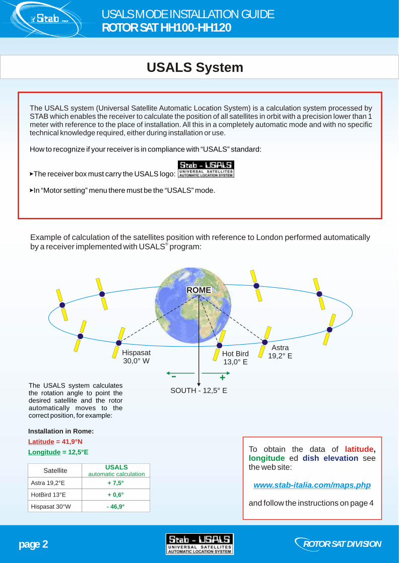
Example of calculation of the satellites position with reference to London performed automatically ®
by a receiver implemented with USALS program:
To obtain the data of , ed see
the web site:
and follow the instructions on page 4
latitudelongitude dish elevation
www.stab-italia.com/maps.php
USALS MODE INSTALLATION GUIDEROTOR SAT HH100-HH120
USALS System
page 2
Installation in Rome:
Latitude = 41,9°N
Longitude = 12,5°E
ROTOR SAT DIVISION
The USALS system (Universal Satellite Automatic Location System) is a calculation system processed by STAB which enables the receiver to calculate the position of all satellites in orbit with a precision lower than 1 meter with reference to the place of installation. All this in a completely automatic mode and with no specific technical knowledge required, either during installation or use.
How to recognize if your receiver is in compliance with “USALS” standard:
>The receiver box must carry the USALS logo:
>In “Motor setting” menu there must be the “USALS” mode.
Astra19,2° EHot Bird
13,0° E
Hispasat30,0° W
SOUTH - 12,5° E
Astra 19,2°E
HotBird 13°E
Hispasat 30°W
Satellite
+ 7,5°
+ 0,6°
- 46,9°
++--
USALS automatic calculation
ROME
The USALS system calculates the rotation angle to point the desired satellite and the rotor automatically moves to the correct position, for example:
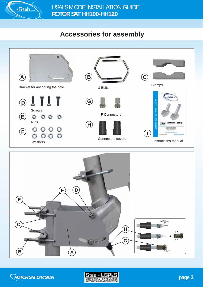
Accessories for assembly
page 3ROTOR SAT DIVISION
Bracket for anchoring the pole
F Connectors
U BoltsClamps
Screws
A B C
D
Connectors covers
H
G
Nuts
E
F
Washers
AB
C
D
E
G
H
F
8mm
15mm
3mm
Instructions manual
I
USALS MODE INSTALLATION GUIDEROTOR SAT HH100-HH120

From the website it is possible to obtain the following data:
, , .
www.stab.italia.com/maps.php
LATITUDE LONGITUDE DISH ELEVATION
These data are essential to perform the installation in USALS mode.
Type the address of installation place
How to obtain the coordinates of installation place
page 4 ROTOR SAT DIVISION
address
USALS MODE INSTALLATION GUIDEROTOR SAT HH100-HH120

Example: installation by STAB address: Seminiato street, 79 - 44034 Ambrogio (FE)
Note the following data:
LATITUDE: 44,9° NLONGITUDE: 12,0° EDISH ELEVATION: 23,2° (for HH100 / HH120 rotors)
On the map you will be also helped by a SOUTH line indicator (tolerance +/- 2°) in order to make the first dish pointing easier as explained later on.
page 5ROTOR SAT DIVISION
If the position is not accurate, drag the red pointer in the correct position.
SOUTH tolerance ± 2°
USALS MODE INSTALLATION GUIDEROTOR SAT HH100-HH120
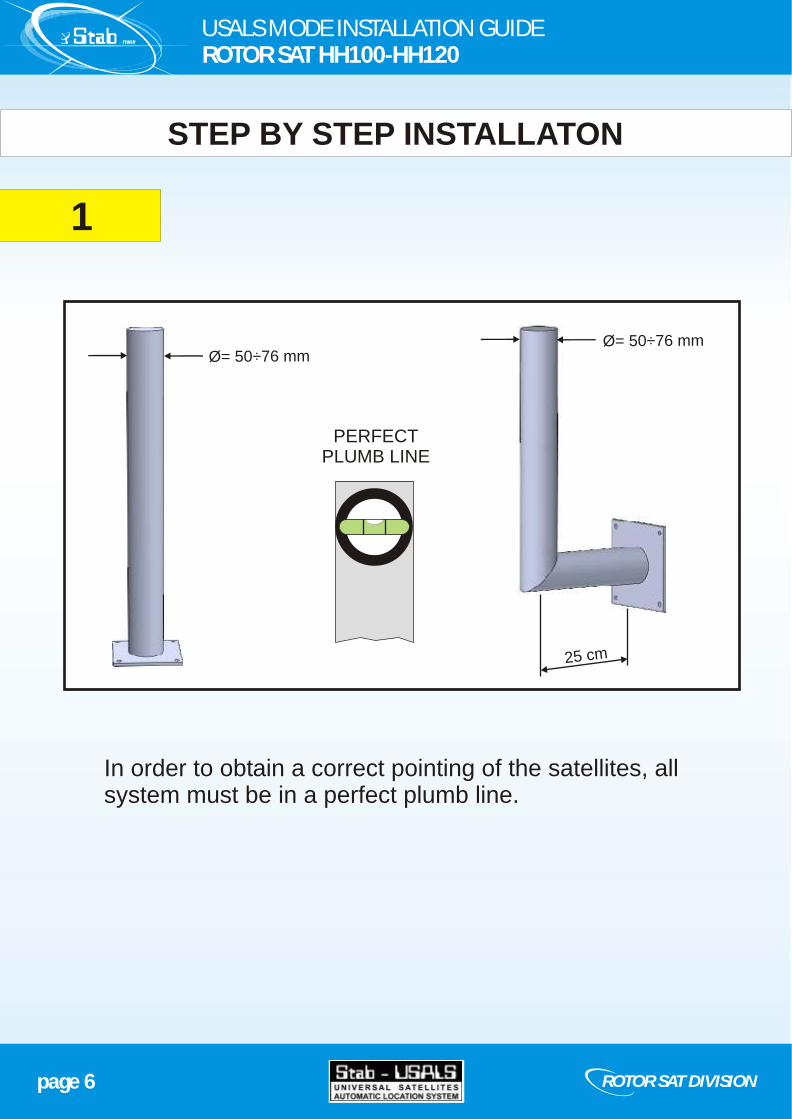
In order to obtain a correct pointing of the satellites, all system must be in a perfect plumb line.
STEP BY STEP INSTALLATON
1
page 6 ROTOR SAT DIVISION
25 cm
Ø= 50÷76 mm
PERFECTPLUMB LINE
Ø= 50÷76 mm
USALS MODE INSTALLATION GUIDEROTOR SAT HH100-HH120
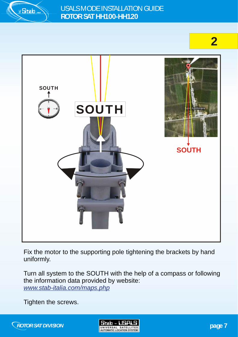
2
SOUTH
SOUTH
page 7ROTOR SAT DIVISION
SOUTH
USALS MODE INSTALLATION GUIDEROTOR SAT HH100-HH120
Fix the motor to the supporting pole tightening the brackets by hand uniformly.
Turn all system to the SOUTH with the help of a compass or following the information data provided by website:
Tighten the screws.
www.stab-italia.com/maps.php

3
page 8 ROTOR SAT DIVISION
USALS MODE INSTALLATION GUIDEROTOR SAT HH100-HH120
Adjust the rotor inclination to your and tighten the fixing screws.
LATITUDE
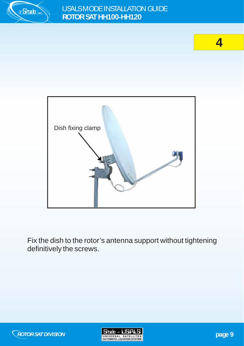
Fix the dish to the rotor’s antenna support without tightening definitively the screws.
4
page 9ROTOR SAT DIVISION
USALS MODE INSTALLATION GUIDEROTOR SAT HH100-HH120
Dish fixing clamp
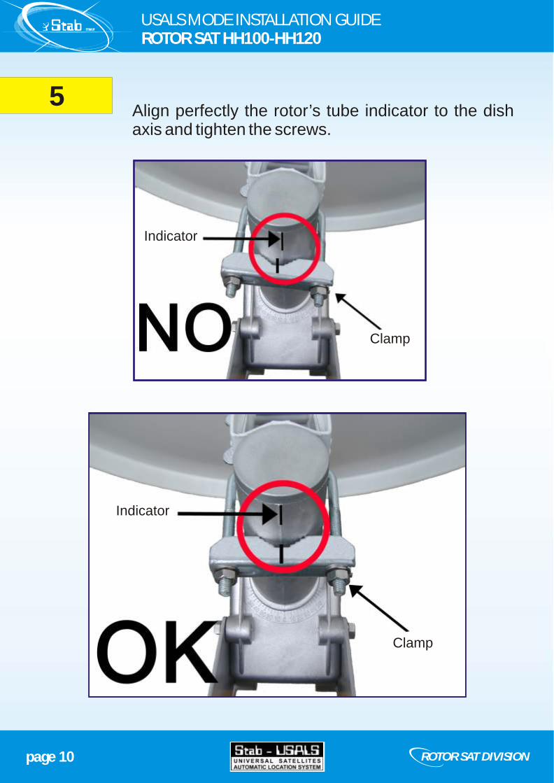
Align perfectly the rotor’s tube indicator to the dish axis and tighten the screws.
5
page 10 ROTOR SAT DIVISION
USALS MODE INSTALLATION GUIDEROTOR SAT HH100-HH120
Clamp
Clamp
Indicator
Indicator
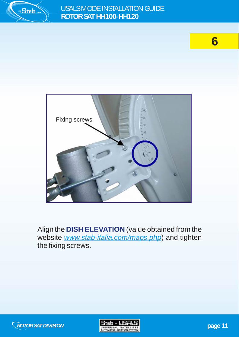
6
page 11ROTOR SAT DIVISION
USALS MODE INSTALLATION GUIDEROTOR SAT HH100-HH120
Align the (value obtained from the website ) and tighten the fixing screws.
DISH ELEVATIONwww.stab-italia.com/maps.php
Fixing screws
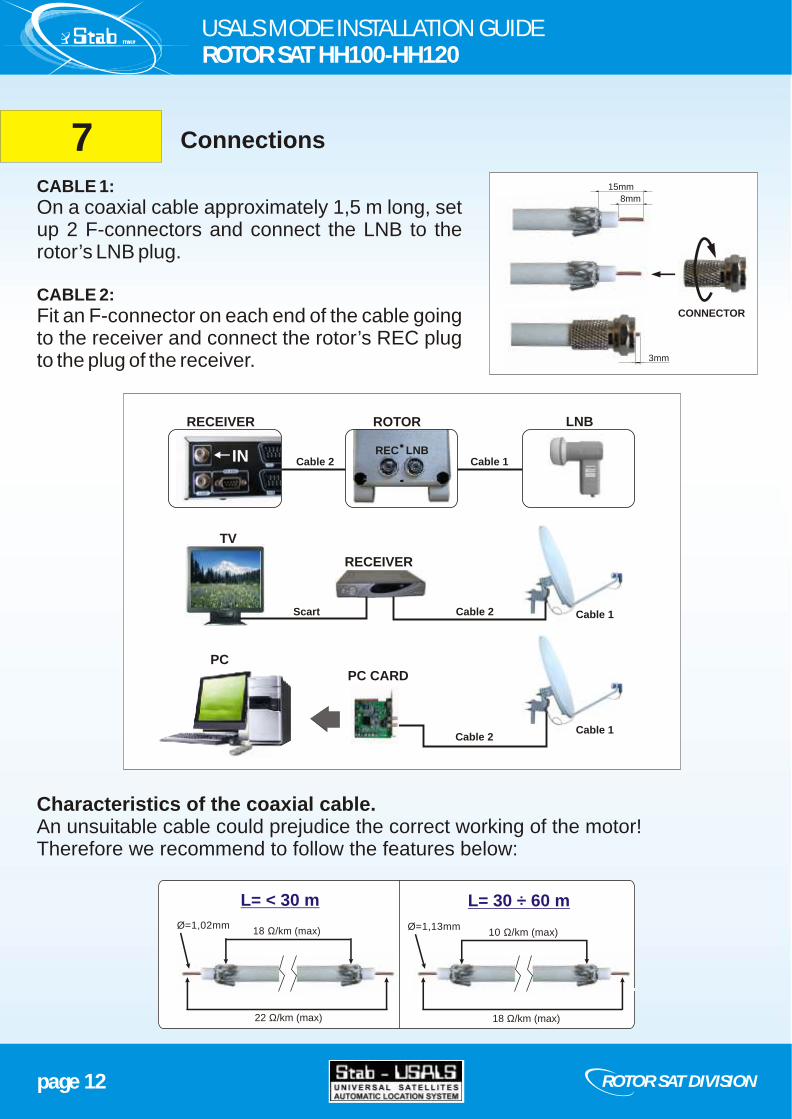
Characteristics of the coaxial cable.An unsuitable cable could prejudice the correct working of the motor!Therefore we recommend to follow the features below:
CABLE 1:
On a coaxial cable approximately 1,5 m long, set up 2 F-connectors and connect the LNB to the rotor’s LNB plug.
CABLE 2:
Fit an F-connector on each end of the cable going to the receiver and connect the rotor’s REC plug to the plug of the receiver.
8mm
15mm
3mm
CONNECTOR
Connections7
page 12 ROTOR SAT DIVISION
L= 30 ÷ 60 m
18 Ω/km (max) 10 Ω/km (max)Ø=1,02mm Ø=1,13mm
22 Ω/km (max) 18 Ω/km (max)
L= < 30 m
USALS MODE INSTALLATION GUIDEROTOR SAT HH100-HH120
LNBREC
ROTOR LNB
Cable 2 Cable 1
Scart Cable 2
Cable 2
Cable 1
Cable 1
TV
RECEIVER
RECEIVER
PC CARDPC
IN

Choose a satellite the nearest to your South (=your Longitude)
example: STAB,
Fill in the empty spaces in the receiver's menu with and(values obtained from the website
)
nearest satellite= HOT BIRD 13°E
Longitudine=12°E
LongitudineLatitudine
www.stab-italia.com/maps.php
Confirm the inserted data with OK.
The motor will automatically be driven to the calculated position.
Wait until the motor stops.
Follow your receiver's instructions manual in order to select the type of istallation in USALS mode
8Settings from the receiver's menu
page 13ROTOR SAT DIVISION
Antenna setup
HotBird 13°E
(1) 10,719 GHz
Vertical - 14V
27,500 MSPS
Tuner Lock
FEC 3/4
Level 31%
Quality 20%
USALS
Stop
Vertical - 14V
44,9° N
Motor settings
Move
Go to reference
LATITUDE
12,0° ELONGITUDE
example of receiver's menu
USALS MODE INSTALLATION GUIDEROTOR SAT HH100-HH120
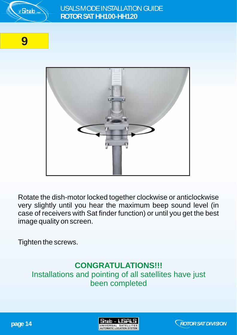
9
page 14 ROTOR SAT DIVISION
USALS MODE INSTALLATION GUIDEROTOR SAT HH100-HH120
Rotate the dish-motor locked together clockwise or anticlockwise very slightly until you hear the maximum beep sound level (in case of receivers with Sat finder function) or until you get the best image quality on screen.
Tighten the screws.
CONGRATULATIONS!!!Installations and pointing of all satellites have just
been completed
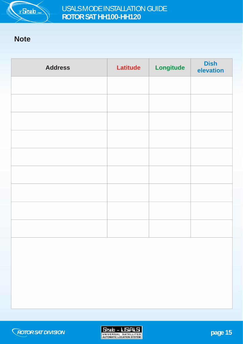
Note
AddressDish
elevation Latitude Longitude
page 15ROTOR SAT DIVISION
USALS MODE INSTALLATION GUIDEROTOR SAT HH100-HH120

STAB S.R.L.Via Seminiato, 79
44034 Ambrogio (FE) ITALYTel.: +39 0532 830739Fax: +39 0532 [email protected]
ROTOR SAT DIVISION
www.stab-italia.com