usage of the lte testbed - crew project tutorial.pdf · –for outdoor enbs sectorized kathrein 800...
TRANSCRIPT

CREW
CREW
The research leading to these results has received funding from the European Union's
Seventh Framework Programme (FP7/2007-2013) under grant agreement n°258301 (CREW project).
Usage of the LTE Testbed A Tutorial
Technische Universität Dresden
Martin Danneberg, Rohit Datta

CREWOutline
■ Introduction
■Available hardware
■Example scenarios
■Setup
■Requirements for 3rd party usage
■Support & contact
■Outlook
1

CREWIntroduction
2
■Usage and operation: ● LTE/LTE-A experimental wireless test bed
E.g. to study cognitive radio (CR) in cellular systems
Operated by TUD Vodafone Chair research team
● LTE-like cellular infrastructure Network parameters are monitored and recorded
● Benchmark the impact of various CR schemes and devices

CREWIntroduction
3
■Basic LTE testbed ● 1 eNB stationary on the desk/tower
● 1 UE portable/moveable in studio rack or bicycle rickshaw

CREWIntroduction
■Hardware features: ● LTE test equipment from SIGNALION
– UL 1.99 GHz, DL 2.18 GHz
– 20 MHz bandwidth
– Supports 2 Tx and 2 Rx channels
– FPGA based
● Basic operating functionality provided by Hardware (Real-time) – Available: RSSI, RSRP, SINR
● Further evaluation of data done in Matlab (Offline) – Available: QAM constellations, CSI, BER
– Link quality metric: BER
4
base station
(eNodeB)
UE (User
Equipment)
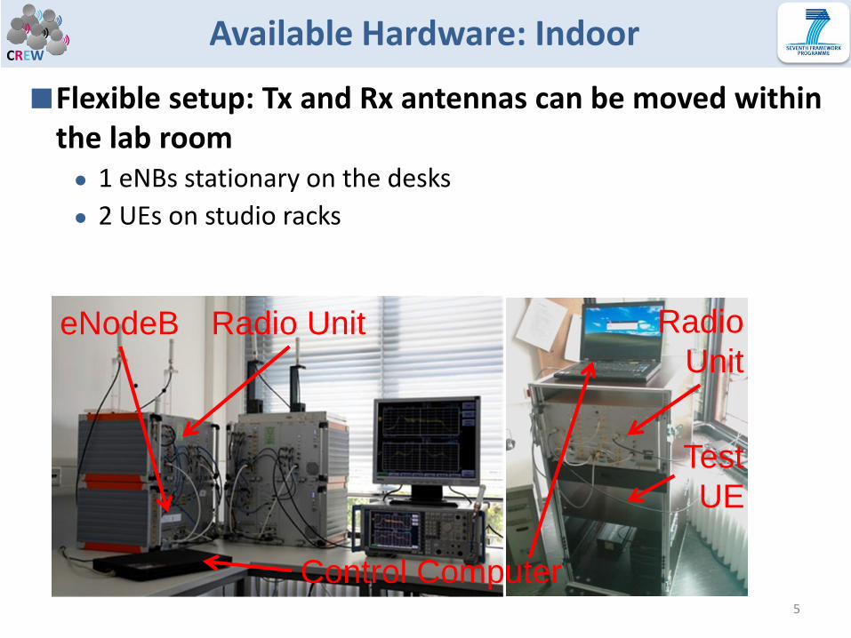
CREWAvailable Hardware: Indoor
5
eNodeB
Test
UE
Radio Unit
Control Computer
Radio
Unit
■Flexible setup: Tx and Rx antennas can be moved within the lab room ● 1 eNBs stationary on the desks
● 2 UEs on studio racks

CREWAvailable Hardware: Outdoor
6
Realistic setup: Two sectors on roof of our institute's building; UEs can roam around indoor and outdoor ● 2 eNBs on the roof
● 1 UE on a rickshaw

CREWAvailable Hardware
■Hardware for CR: ● SIGNALION Hardware-in-the-Loop (HaLo)
● Transmits arbitrary signals
● Different signal wave forms possible (e.g. OFDM, GFDM)
● Signal is generated by Matlab and stored in a Hardware-Buffer
■Different parameters controllable ● Bandwidth
● Frequency
● Attenuation
● Timing
● Waveform
7
Secondary system
(transmitting only)

CREWAvailable Hardware
■Hardware for CR: ● NI USRP-2920
● Software-programmable radio transceivers designed for wireless communications teaching and research
● Spectrum sensing algorithm for LTE signals from iMinds
● Frequency range: 50MHz-2.2GHz
● Instantaneous real-time bandwidth 20MHz (16bit samples), 40MHz (8bit-samples)
8
Sensing device
(receiving only)

CREWAvailable hardware
9
■Other ● 3 bicycle rickshaws
– 110 Ah Battery (can supply an UE for around 2-4 hours) – 12 V to 230 V converter (max. load 1 kW) – 19” Rack to mount UE’s, HALO, USRP, … – Internet access via 3G card or Campus WLAN
● Antennas – For UEs and indoor eNBs omnidirectional Kathrein 800 10431 – For outdoor eNBs sectorized Kathrein 800 10551
● GPS receiver – For time synchronization of eNBs – For position tracking of UEs
● Various coaxial cables, attenuators, splitters ● Measurement equipment
– R&S FSH4 and FSQ8 spectrum analyzer – Signal generator
● Antenna positioning tables (PC controlled stepper motor)

CREW
■Real world scenario: ● M2M device uses LTE uplink for communication
Example scenarios
10
LTE Primary link M2M Secondary link

CREWExample scenarios
11
Observer (Spectrum Analyzer:
R&S FSH4, R&S FSQ8) base station
(eNodeB)
LTE UE # 1 (User
Equipment) HaLo device
(transmitting only)
Primary link Secondary link
■Basic setup • E.g. to study impact from
secondary waveform on primary system
● Parameters of primary link – Frequency
– Attenuation
– Bandwidth
● Parameters of secondary link – Waveform (OFDM, GFDM,
UMTS, …)
– Frequency
– Attenuation
– Bandwidth

CREWExample scenarios
■Basic setup extended with sensing device ● E.g.: NI USRP-2920 or
Spectrum Analyzer
● To study energy based sensing algorithms
12
Base station
(eNodeB)
LTE UE # 1 (User
Equipment)
HaLo device
(transmitting only)
Primary link
Secondary link
Sensing device
(receiving only)
Information
about free
channels

CREWExample scenarios
■Basic setup in outdoor use
■Possible scenarios: ● Study differences
compared to indoor environment
● Evaluate sensing algorithms
● Test GPS location based spectrum management systems (in combination with sensing)
13
eNB
eNB
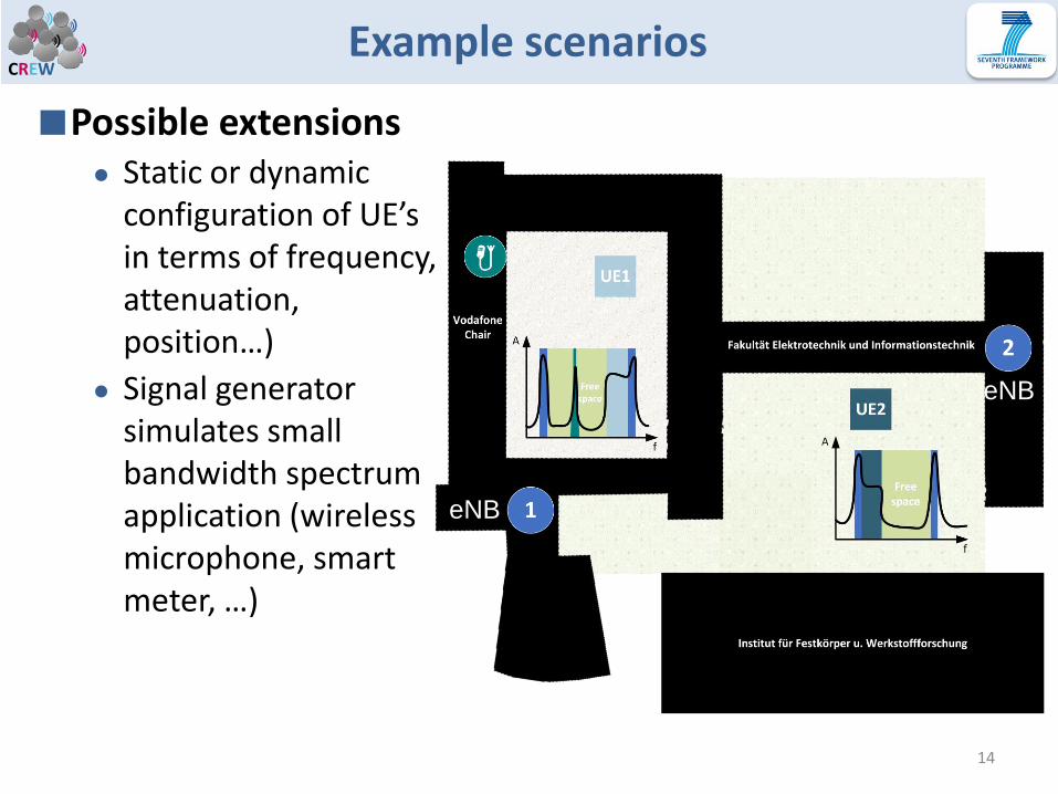
CREWExample scenarios
■Possible extensions ● Static or dynamic
configuration of UE’s in terms of frequency, attenuation, position…)
● Signal generator simulates small bandwidth spectrum application (wireless microphone, smart meter, …)
14
eNB
eNB

CREWSetup
15
Observer (Spectrum Analyzer:
R&S FSH4, R&S FSQ8) base station
(eNodeB)
LTE UE # 1 (User
Equipment)
HaLo device
(transmitting only)
Primary link Secondary link
Sensing device
(receiving only)

CREWSetup
1. Start base station Configuration file must be prepared.
16
1 Select config file
2 eNB reset
3 Config
CREWSetup
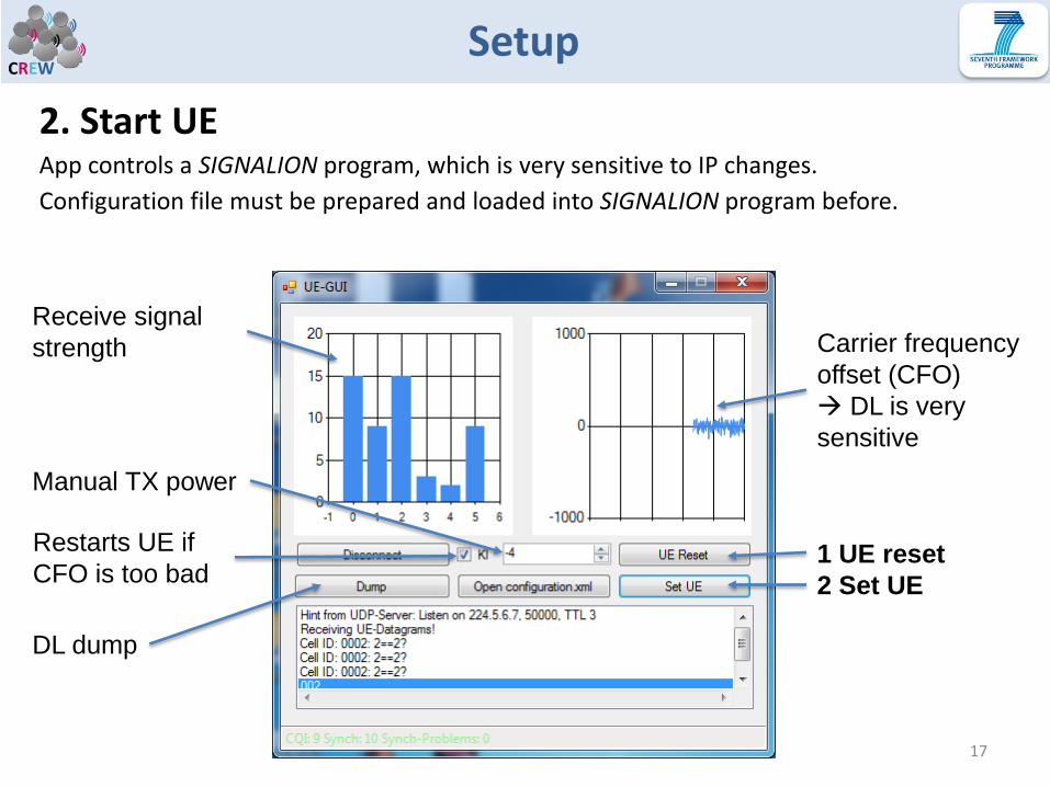
2. Start UE App controls a SIGNALION program, which is very sensitive to IP changes.
Configuration file must be prepared and loaded into SIGNALION program before.
17
1 UE reset
2 Set UE
Carrier frequency
offset (CFO)
DL is very
sensitive
Receive signal
strength
Manual TX power
DL dump
Restarts UE if
CFO is too bad
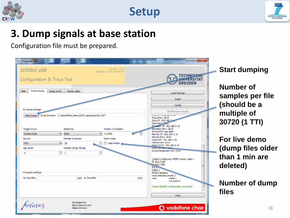
CREWSetup
3. Dump signals at base station Configuration file must be prepared.
18
Start dumping
Number of
samples per file
(should be a
multiple of
30720 (1 TTI)
For live demo
(dump files older
than 1 min are
deleted)
Number of dump
files

CREWSetup
4. Evaluate dump files Dump files have to be copied in a special folder structure.
MATLAB 2013b 32bit Runtime must be installed. App uses a DLL with a MATLAB script.
19
1 Select dump dir
2 Select mode
Demo mode evaluates all dump files
Live mode evaluates only the newest file
3 Start

CREWSetup
■Controlling the secondary waveform parameters MATLAB 2013b 32bit Runtime must be installed. App uses a DLL with a MATLAB script.
20
1 Generate
waveform
2 Downloading
3 Transmitting

CREWSetup
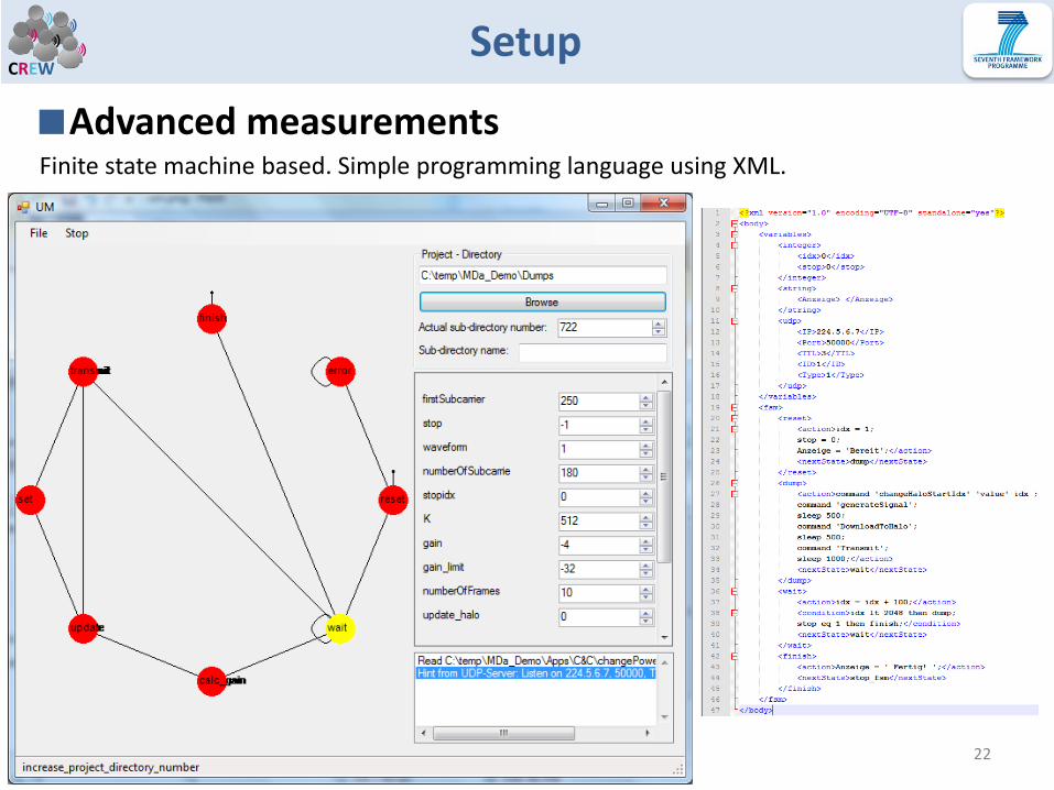
■Advanced measurements ● Parameter via UDP from C&C-Server changeable
● Script controlled measurements possible
● C# based application suite – Created with Visual Studio
– Working under Win XP, Vista, 7 and Linux
– Only requirement: .NET 4 or MONO installed
● Remote controllable Applications available for: – UE, GPS tracking, Antenna positioning devices, HALO, Matlab, R&S
spectrum analyzer, serial console based devices (e.g.: eNB’s power amplifiers), file management
– iMinds USRP sensing software is currently under work
● With a little effort, every device can be added – Network communication in separate class available
21
CREWSetup
■Advanced measurements Finite state machine based. Simple programming language using XML.
22

CREWRequirements for 3rd party usage
Aspects to consider
■Scenario description ● Indoor, outdoor
■Hardware requirements ● Size
● Power supply
■Software requirements ● Windows, Linux
● Internet access
● Script controlled measurements with own devices Test bed uses MATLAB & C# .NET
■Parameters and metrics
23

CREWAvailable support
■Preparing indoor/outdoor measurement
■Setting LTE test equipment up
■Applying new waveforms to the HALO-Box (time signal is needed)
■Assisting to prepare script controlled measurements
■Documentation of test bed facilities ● Overview SIGNALION SORBAS and HALO test equipment
● Datasheet of R&S spectrum analyzers
24

CREWContact
■ Team E-Mail address: [email protected]
■ Fax: +49 351 463 41 099
■ Address: Georg-Schumann-Str. 11, D-01187 Dresden
25
Dr.-Ing. Andreas Festag
Phone: +49 351 463 41 024
E-Mail: [email protected]
Dipl.-Ing. Martin Danneberg
Phone: +49 351 463 41 095
E-Mail: [email protected]
M. Tech. Rohit Datta
Phone: +49 351 463 41 053
E-Mail: [email protected]

CREWOutlook
■Migrate to new hardware platform ● NI PXI System with Labview software environment
● FPGA-based
■ Implementation of a GFDM Transceiver
26
NI FlexRIO FPGA-module 7965 RF Transceiver module
5791, 5781
PXI 1082 Chassis

CREW
CREW
The research leading to these results has received funding from the European Union's
Seventh Framework Programme (FP7/2007-2013) under grant agreement n°258301 (CREW project).
Thank you!
CREWBackground: Cellular Networks
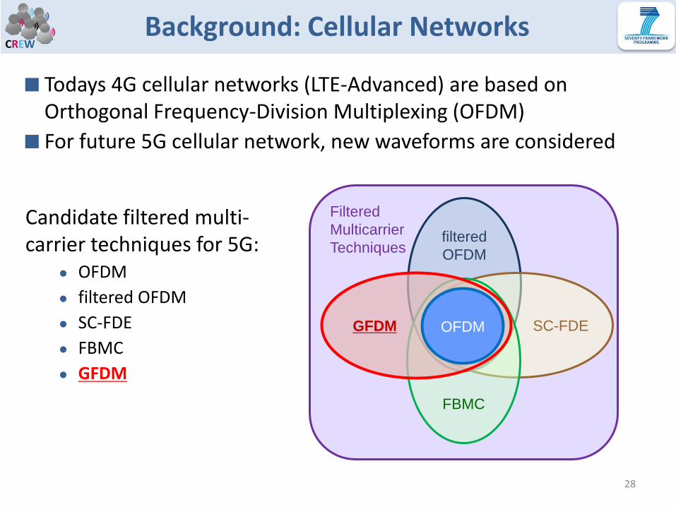
■ Todays 4G cellular networks (LTE-Advanced) are based on Orthogonal Frequency-Division Multiplexing (OFDM)
■ For future 5G cellular network, new waveforms are considered
28
Candidate filtered multi-carrier techniques for 5G:
● OFDM
● filtered OFDM
● SC-FDE
● FBMC
● GFDM
Filtered
Multicarrier
Techniques filtered
OFDM
SC-FDE
FBMC
GFDM OFDM

CREWBackground: Cellular Networks
■ GFDM: Generalized Frequency Division Multiplexing
● Non-orthogonal multi carrier scheme with pulse shaping
● Data is spread on time-frequency grid
■ GFDM main benefits compared to OFDM
● Relaxed requirements on orthogonality and synchronism
● Less out-of-band interference and lower peak-to-average power ratio
● Time-frequency resource grid enables flexible resource assignment
● Accommodate low-rate and high-rate users
■ GFDM potential issues (being increasingly alleviated by ongoing research)
● Self-interference and higher complexity
29
GFDM resource grid
Circular sub-carrier pulse shape Non-orthogonal sub-carriers
CREWBackground: Cellular Networks
■ For future coexistence of 4G and 5G networks, GFMD has favorable features ● Spectrally shaped sub-carriers
● Flexible resource grid
■ Coexistence scenario ● Host system is OFDM with a number of silenced subcarriers
● Guest system is designed to match the created white space
■ GFDM as guest system ● creates less interference to host system
● causes lower BER in host system see next slide
30

CREWBackground: Cellular Networks
31
0 10 20 30 40 50 60-60
-50
-40
-30
-20
-10
0
10
20
normalized frequency f/fk
po
wer
in d
B
OFDM host system
GFDM guest system
OFDM guest system
N. Michailow et al. “Integration of a GFDM secondary system in an OFDM primary system”, Proc. FNMS 2011
OFDM
host
OFDM
host
OFDM
guest
OFDM
guest
OFDM
host
OFDM
host
GFDM
guest
GFDM
guest
0 2 4 6 8 10 12 14
10-4
10-3
10-2
10-1
100
Eb/N0 [dB]
BER
OFDM theory
OFDM host
from Setup 1
OFDM host
from setup 2
OFDM guest
from Setup 1
GFDM guest
from Setup 2