u.s.a. and countries outside the eu . . . . . . . ....
TRANSCRIPT

1
FLEXUS 2
Dansk . . . . . . . . . . . . . . . . . . . . . . . . . .2English. . . . . . . . . . . . . . . . . . . . . . . . . 16Svenska . . . . . . . . . . . . . . . . . . . . . . . . 30U.S.A. and countries outside the EU . . . . . . . . 44

16
GB . . . . . . .FLEXUS 2
Item no.P07 - XXXXXX
1.00 . . . . . . . . .Purpose and Use . . . . . . . . . . . . . . . . . . . . . . . . . . . . . . . . . . . . . . . . . . . . 171.01 . . . . . . . . .Producer . . . . . . . . . . . . . . . . . . . . . . . . . . . . . . . . . . . . . . . . . . . . . . . . . . . . 171.02 . . . . . . . . .Aim and Use . . . . . . . . . . . . . . . . . . . . . . . . . . . . . . . . . . . . . . . . . . . . . . . . . 171.03 . . . . . . . . . Important/Warnings . . . . . . . . . . . . . . . . . . . . . . . . . . . . . . . . . . . . . . . . . . . . 171.04 . . . . . . . . .Unpacking and Preparation . . . . . . . . . . . . . . . . . . . . . . . . . . . . . . . . . . . . . . 181.05 . . . . . . . . .Assembly Prior to Use . . . . . . . . . . . . . . . . . . . . . . . . . . . . . . . . . . . . . . . . . . 181.06 . . . . . . . . .Electrical Connection . . . . . . . . . . . . . . . . . . . . . . . . . . . . . . . . . . . . . . . . . . . 18
2.00 . . . . . . . . .Description of Functions . . . . . . . . . . . . . . . . . . . . . . . . . . . . . . . . . . . . . . 192.01 . . . . . . . . . Labels . . . . . . . . . . . . . . . . . . . . . . . . . . . . . . . . . . . . . . . . . . . . . . . . . . . . . . 192.02 . . . . . . . . .Operation . . . . . . . . . . . . . . . . . . . . . . . . . . . . . . . . . . . . . . . . . . . . . . . . . . . . 192.03 . . . . . . . . .Safety Functions . . . . . . . . . . . . . . . . . . . . . . . . . . . . . . . . . . . . . . . . . . . . . . 222.04 . . . . . . . . .Accessories . . . . . . . . . . . . . . . . . . . . . . . . . . . . . . . . . . . . . . . . . . . . . . . . . . 22
3.00 . . . . . . . . .Dismantling and Transport . . . . . . . . . . . . . . . . . . . . . . . . . . . . . . . . . . . . . 253.01 . . . . . . . . .Dismantling . . . . . . . . . . . . . . . . . . . . . . . . . . . . . . . . . . . . . . . . . . . . . . . . . . 253.02 . . . . . . . . . Transportation . . . . . . . . . . . . . . . . . . . . . . . . . . . . . . . . . . . . . . . . . . . . . . . . 253.03 . . . . . . . . .Packaging During Transportation . . . . . . . . . . . . . . . . . . . . . . . . . . . . . . . . . 25
4.00 . . . . . . . . .Maintenance and Storage . . . . . . . . . . . . . . . . . . . . . . . . . . . . . . . . . . . . . . 264.01 . . . . . . . . .Cleaning . . . . . . . . . . . . . . . . . . . . . . . . . . . . . . . . . . . . . . . . . . . . . . . . . . . . . 264.02 . . . . . . . . .Keeping and Storage . . . . . . . . . . . . . . . . . . . . . . . . . . . . . . . . . . . . . . . . . . . 264.03 . . . . . . . . .How to Avoid Corrosion? . . . . . . . . . . . . . . . . . . . . . . . . . . . . . . . . . . . . . . . . 264.04 . . . . . . . . .What Maintenance Should the Owner Carry Out Him/Herself? . . . . . . . . . . 26
5.00 . . . . . . . . .Service and Useful Life . . . . . . . . . . . . . . . . . . . . . . . . . . . . . . . . . . . . . . . . 265.01 . . . . . . . . .Useful Life and Servicing . . . . . . . . . . . . . . . . . . . . . . . . . . . . . . . . . . . . . . . . 265.02 . . . . . . . . . Fuses . . . . . . . . . . . . . . . . . . . . . . . . . . . . . . . . . . . . . . . . . . . . . . . . . . . . . . . 275.03 . . . . . . . . . Inspection – All-round . . . . . . . . . . . . . . . . . . . . . . . . . . . . . . . . . . . . . . . . . . 275.04 . . . . . . . . . Fault-Finding – The Bed Does Not Work . . . . . . . . . . . . . . . . . . . . . . . . . . . . 27
6.00 . . . . . . . . . Technical Specifications . . . . . . . . . . . . . . . . . . . . . . . . . . . . . . . . . . . . . . 28
7.00 . . . . . . . . .EC-Declaration of conformity . . . . . . . . . . . . . . . . . . . . . . . . . . . . . . . . . . . 29

17
1.00 Purpose and Use
1.01 ProducerV. Guldmann A/SGraham Bells Vej 21-23A DK - 8200 Århus NDenmarkTel. + 45 8741 3100Fax + 45 8741 3131
1.02 Aim and Use
The Aim of the ManualThe manual primarily describes the standard model with 3 motors. Other versions are mentioned in as far as their operation differs from the standard model.It is therefore important to be aware of which version of the nursing bed one is in possession of, as functions may be described which are not found on all nursing beds.
UseThe Flexus 2 is a nursing bed for use in institutions, residential homes and for home care. A nursing bed differs from a normal bed primarily in that it acts as both an aid for the user and as a tool for the helper. This is reflected in the fact that the height of the bed is adjustable, for example, and in that the user is offe-red a number of different resting positions, as the bed board under the mattress is divided into four sections which can be angled together, or individually.
Professionally-trained personnel are expected to use this aid/tool when the bed is used in an institution or for home care.Important! It is not to be recommended to place the bed direct on an untre-ated/oil-treated wooden floor, as this can result in discoloration of the floor.
1.03 Important/Warnings• Read all the operating instructions before using the bed.• The bed’s MAX. load of 240 kg, incl. mattress and accessories, must not be
exceeded.• The bed should only be used on a level and flat underlay.• Avoid running into people or objects with the bed.• The bed should not be weighed down with more than one person in addition to
the user.This eliminates the chance of the bed overbalancing and overturning.• When adjusting the height of the bed to a lower position, a check should
always be made that there is free space under the bed. Pay attention to children, pets, etc., under the bed.
• When adjusting the moving parts of the bed, be very careful and ensure that neither limbs nor objects can get trapped.
• The bed is designed for adults only.• Only Guldmann approved equipment must be mounted on the bed.
18
• The bed should be left by the carer in a position in which nobody can get hurt, i.e. in the lowest position, whether it is in use or not.
1.04 Unpacking and Preparation
Visual ControlIf the packaging is damaged on receipt, the parts of the bed should be inspected carefully for visible imperfections, defects or faults. If damage is suspected, the bed must not be used before qualified service personnel or Guldmann Service Team have approved it.
Contents1. Bed base on wheels with brakes2. Bed board with 4-section bed board3. Wooden head and foot boards 4. Hand control5. Manual
Accessories, lifting pole, bed guards, mattress, etc., as required.
1.05 Assembly Prior to UseRemove the string, cardboard and transport blocks used for transportation from the head and foot boards.Mount the wooden head and foot boards in the holders on the bed board. Unpack and mount any accessories.
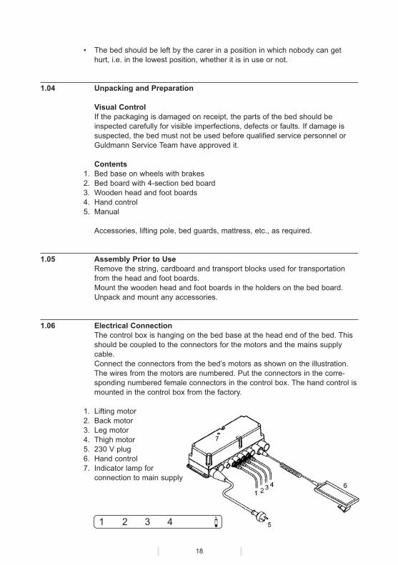
1.06 Electrical ConnectionThe control box is hanging on the bed base at the head end of the bed. This should be coupled to the connectors for the motors and the mains supply cable.Connect the connectors from the bed’s motors as shown on the illustration.The wires from the motors are numbered. Put the connectors in the corre-sponding numbered female connectors in the control box. The hand control is mounted in the control box from the factory.
1. Lifting motor2. Back motor3. Leg motor4. Thigh motor5. 230 V plug6. Hand control7. Indicator lamp for
connection to main supply

19
Important!The connectors must never be switched around.
The connectors to the control box are fitted with watertight seals. The con-nectors should be pressed right into place in the control box in order to work. Dampen the rubber seals before pressing them into place.The 230 V connector from the control box should be connected to a power socket.The green lamp on the control box lights up when the connector switch is turned on and the bed is ready for use.
2.00 Description of Functions
2.01 Labels
2.02 Operation
Summary of Functions1. 4-section bed board2. Fittings for lifting pole3. Hand control4. Finger screws for bed guards5. Control box6. Bed base7. Finger screws to divide the bed frame8. Wheels with brakes9. 2/4 section division
10. Emergency lowering unit for back part11. Finger screws for bed extension
Flexus 2 Se. No. M Y XXXXXXXX
Electrical protection class IIIP 66

20
Back/thigh section
Bedboard
Back section
Thigh section
Leg section
Adjustment of the Bed – ManuallyCertain basic functions can only be carried out by the helper or user before he/she goes to bed. The user is unable to operate the manual functions from the bed. Such functions include moving the bed; applying the brakes to the wheels, and raising/lowering the leg section on Flexus 2 versions with mecha-nical release in the form of gas cylinders.
Manual adjustment of the leg section is carried out by activating the large blue handle which can be operated from both sides of the bed. When the handle is pressed up against the bed frame, the leg section will move upwards. If the leg section needs to be brought back to the horizontal position, or just downwards, the handle should be activated in the same way. Manual adjustment of the bed board is easiest when someone is lying in the bed. The function is carried out as illustrated on the label shown, which is fitted on the bed frame.
Adjusting the Bed – ElectricallyFlexus 2 can be fitted with 2 to 4 motors. These electric motors operate the height of the bed, and adjust the back and thigh/leg sections. The 4th motor is for separate adjustment of the thigh section.The standard version of Flexus 2 is fitted with three motors.
The various functions are adjusted by using the up/down buttons on the hand control enclosed, which is operated just as effectively by either user or helper. These are illustrated as pictograms, which give a clear indication of which button belongs to which function, and which are further supported by identical pictograms placed on the bed where the function in question applies.The hand control is fitted with a spiral wire and a hook to hang it up, which make it possible to place the hand control several places on the bed where both user and helper can reach it.
Back/thigh section
Bedboard
Leg section
21
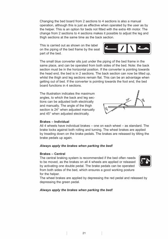
Changing the bed board from 2 sections to 4 sections is also a manual operation, although this is just as effective when operated by the user as by the helper. This is an option for beds not fitted with the extra 4th motor. The change from 2 sections to 4 sections makes it possible to adjust the leg and thigh sections at the same time as the back section.
This is carried out as shown on the label on the piping of the bed frame by the seat part of the bed.
The small blue converter sits just under the piping of the bed frame in the same place, and can be operated from both sides of the bed. Note: the back section must be in the horizontal position. If the converter is pointing towards the head end, the bed is in 2 sections. The back section can now be tilted up, whilst the thigh and leg sections remain flat. This can be an advantage when getting out of bed. If the converter is pointing towards the foot end, the bed board functions in 4 sections.
The illustration indicates the maximum angles, to which the back and leg sec-tions can be adjusted both electrically and manually. The angle of the thigh section is 24° when adjusted manually and 45° when adjusted electrically.
Brakes – IndividualAll 4 wheels have individual brakes – one on each wheel – as standard. The brake locks against both rolling and turning. The wheel brakes are applied by treading down on the brake pedals. The brakes are released by tilting the brake pedals up again.
Always apply the brakes when parking the bed!
Brakes – CentralThe central braking system is recommended if the bed often needs to be moved, as the brakes on all 4 wheels are applied or released by activating one double pedal. The brake pedals can be operated from both sides of the bed, which ensures a good working posture for the helper.The wheel brakes are applied by depressing the red pedal and released by depressing the green pedal.
Always apply the brakes when parking the bed!

22
Extension of the bedThe bed can be extended up to 200 mm. Loosen the two blue finger screws, see arrow, on the bed board frame and pull out the foot board to the required length. Tighten the finger screws again.
Then loosen the two blue finger screws placed under the foot section of the bed board. Pull out the mattress stop until 25 mm from the foot board of the bed and tighten the finger screws again.
Important!The extended bed will not be able to meet the standard requirement for sta-bility with a load on the foot end of 135 kg, but will begin to tilt with a load of approx. 80 kg. The foot board must therefore only be weighed down with a maximum load of 50 kg, when the bed is extended.
2.03 Safety Functions
Description of the emergency lowering functionThe motor for the back section is fitted with an emergency lowering unit, which is marked on a red operating handle with the label shown.A constant light pressure on the red handle will bring the back section down to the horizontal position. Once the emergency lowering unit has been used, the fault with the bed should be put right before the bed is used again.
The emergency lowering should only be used if there is a special need for it. If the emergency lowering is used in connection with a failure, contact the distributor before using the bed again.
For users who are particularly dependent on adjustment routines which must not be broken, we would recommend a bed with a battery back-up – see under accessories.
2.04 Accessories
Bed GuardsBed guards should be assembled in the holes on the top of the bed board frame.In order to facilitate assembly of the bed guards, it may be necessary to loosen the finger screws which divide the bed board. The bed guards should be locked to the frame with the two blue finger screws found under the holes on the underneath of the frame.Normally the bed guard lock is turned towards the head of the bed. Where the

23
user could activate the lock unintentionally, the bed guard should be turned 180 degrees so that the lock turns towards the end of the bed instead.The bed guards are folded down by releasing the lock in one end and at the same time pushing the upper pipe of the bed guard downwards.
Check that no limbs are placed between the ribs of the bed guard, when folding it down. Therefore, press only the upper pipe.
Ensure that the bed guards are locked when they are pulled up again.The bed guards can be taken off by loosening the blue finger screws and lif-ting the bed guards off the frame.
Bed guard with cord driveA bed guard variant with cord drive, which releases the lock, is available. This bed guard can be used by all independent users.
Warning: Bed guard with cord drive can be released unintentionally.
Small bed guardFasten the bed guard to the frame of the bed board with the two blue finger screws. Please note that there is a risk of getting jammed.
Lifting poleThe lifting pole should be put in the hole in the left or right corner of the head end, as required. Ensure that the lifting pole is steered into place in the hole so that it cannot swing from side to side.
Mount the handgrip on the lifting pole inside the stop pawl. Check that the black non-skid material is fitted round the lifting pole.
Support handleMount the support handle on the frame of the back section with the enclosed blue finger screws - see illustration.
Please note that there is a risk of getting jam-med between the bed guard and the support handle.
Fender wheels, vertical/horizontalIf the bed is being moved often, it is practical to mount fender wheels verti-cally and horizontally to protect walls, door cases, sockets etc.
Battery BackupAs the Flexus 2 is operated entirely or partly by electricity, and is not fitted with a battery backup as standard, it is susceptible to power cuts.A battery backup is therefore recommended if the user is vulnerable to irre-gularities, or if he/she is particularly dependent on adjustment routines which must not be broken.

24
If the bed is fitted with battery backup please note that it will be necessary to remove not only the connector from the socket, but also the connectors from the control box or the hand control, if the bed is not supposed to be operated.
Luxury wooden head/foot boards and bed guards
Mounting of head/foot boardsUnscrew the wooden plate used for transportation from the head/foot board holders on the bed frame. Screw the M6 bolts (packed with the head/foot boards) loosely two turns down into the threaded holes.
Place the premounted head or foot board care-fully on the holders on the bed and tighten the bolts with a 4 mm Allen screw.
Mounting of bed guardsPosition the steering pins at one end of the bed guard in the carved track of the head/foot board. Raise the other end of the bed guard to top edge of the head/foot board making sure that the steering pins first inserted stay in the track. Press the 4 pins into the bed guard and press the bed guard firmly on to the head/foot board next to the carved track. Push all 4 pins into position in the track below the S-curved section. Make sure that the two steering pins connected with the steel wire in the mid position are inserted at the same time in order not to bend the steel wire. Lower the bed guards to the bottom of the track.
The bed guards are demounted by raising them at one end. Press the pins into the bed guard and press the bed guard on to the head/foot board next to the curved track. Make sure that the pins at the opposite end stay in the track.
Transport the bed guards carefully and always in the horizontal position.
OperationStand at the middle of the bed and raise the upper bed guard with both hands.To raise: Raise the bed guards by sliding them in the track right round the curved section at the top, where they are kept in position.To lower: Tilt the upper bed guard towards the bed and slide it round the curved section and down the track. It is important to keep the bed guards in a horizontal position and to adjust both ends simultaneously.
Cleaning and maintenance Head/foot boards and bed guards must not be sprayed nor washed, but shall be cleaned with a damp sponge. Like the bed they cannot tolerate auto-claving. Grease the S-curved section of the head/food boards with silicone or for instance stearine.Grease the movable parts of the bed guards with Molykote grease and, in particular, the lubricating holes of the lower bushings.

25
3.00 Dismantling and Transport
3.01 Dismantling
Dismantling the bed board – To be carried out by 2 persons
1. The bed board can be taken off the bed base of the bed for transportation.2. Apply the brakes to the wheels of the bed.3. Take the connectors from the motors and the hand control out of the control
box.4. Remove the end plates, the mattress and the lifting pole, if applicable.5. Tip the leg part of the bed board up to the vertical position in order to get to
the lock mechanism for the bed board.6. Uncouple the lock by turning the two plain retaining washers loose, and pul-
ling them over onto the opposite side of the locking pin.
7. Lift the foot end of the bed board up/free and push it down onto the head end until the scissor wheel is free.
8. The head end can now also be lifted up, and the bed board is then released from the bed base.
3.02 TransportationThe bed can be divided in two for transportation and storage.
1. Lift the wooden head and foot boards off, and remove the lifting pole and bed guards.
2. Lift up the back section of the bed board to the vertical position and lift it off. 3. Remove the grey finger screws which divide the bed frame, and pull out the
head end. 4. Uncouple the bed board from the bed base (see section 3.1).
Important!!If the bed/bed board is transported vertically, the head and foot part of the bed board should be fastened to the frame.
3.03 Packaging During TransportationGuldmann recommends that the bed always be transported in its original packaging, when separated into parts.

26
4.00 Maintenance and Storage
4.01 CleaningWhen cleaning the bed the connectors must be mounted in the control box.Wash the bed with a sponge or brush and soapy water. It can also be spray-ed or washed down. The bed should be dried thoroughly after washing, as it can be damaged if it remains damp. Remember to take the wooden head and foot boards off if the bed is sprayed or washed down.Never use acids, bases or solvents when cleaning.The bed cannot tolerate autoclaving.
4.02 Keeping and StorageThe bed should be stored in a dry room, and it should not therefore be stored in bathrooms, damp cellars, or the like.
4.03 How to Avoid Corrosion?The bed should not be stored/kept in damp surroundings for a longer period of time. In such circumstances, water vapour can condense to water on the bed, which may give rise to corrosion/rust in bearings, and in steel and move-able parts. The bed should not be exposed to sudden cold/heat.In places with aggressive dampness, the bed is particularly exposed to the formation of rust, and should therefore always be removed from such places after use.
4.04 What Maintenance Should the Owner Carry Out Him/Herself?Regular cleaning.Movable parts should be lubricated after cleaning, or once a year as a minimum. Ask Guldmann for a lubrication chart.
5.00 Service and Useful Life
5.01 Useful Life and ServicingAt least once a year the bed must be inspected and this service inspection has to be carried out by qualified service personnel or by Guldmann Service Team.
The bed has an expected useful life of 10 years provided that a yearly inspec-tion has taken place. After this period, the bed should be assessed for future use by qualified service personnel.
Spare part lists and drawings can be ordered from the producer or the distributor.

27
5.02 FusesBatteries and fuses should be replaced by qualified personnel or by Guldmann Service Team.
5.03 Inspection – All-roundA report of what has been checked and replaced should be kept during the service inspection. Parts, which are worn or defective, should be replaced with new spare parts from Guldmann™.
1. Visual Control of the Product• Check that there is no wear on the product.• Check that there are no faults with the product.• Check that there is no other form of damage to the product.
2. Testing of the Product, as for Normal Use• Check all the product’s functions, loaded and unloaded. • Check that the emergency lowering works.• Check that the voltage indicator works. 3. Control of the Electrical State of the Product• Check electrical functions and signals.• Check the wiring for faults and defects.• Check the cable bushings.• Check connection possibilities, connectors, etc. 4. Control of the Mechanical State of the Product• Clean dirt and other impurities from the product.• Inspect and assess the vital parts of the product.• Replace defective and worn parts of the product.• Lubricate the product.• Check and tighten all moving parts. 5. Go Through Pt. 2 Again to Check That Everything Works 6. Did Any New Problems Arise/Were New Problems Noted in Pt. 5?• If new problems arose, go back to pt. 2.• If no new problems were noted, conclude the inspection.
5.04 Fault-Finding – The Bed Does Not Work
1. Is there a light in the control box? Yes : See point 3. No : See point 2.
2. Is the plug switched on? Yes : Replace the control box. No : Press the wire into place/switch on the plug. The bed still does not work. See point 3.
28
3. Is the hand control mounted correctly? – It should be pressed in hard! Yes : See point 4. No : Mount the hand control – Press it in hard! The bed still does not work. See point 5.
4. Are the motor cables inserted correctly in the control box? Yes : See point 5. No : Insert the cables. The bed still does not work. See point 5. 5. Is there visible damage to the motor cable? Yes : Contact Guldmann Service! No : Replace the hand control and also the control box if necessary – or contact Guldmann Service!
6.00 Technical Specifications
Bed with Ø125 mm wheels, dimensions (W x L) . . . . . . .985 x 2140-2340 mmHeadroom between floor and bed base . . . . . . . . . . . . . . . . . . . . . . . 170 mmHeight adjustment of bed board . . . . . . . . . . . . . . . . . . . . . . . .360 to 820 mm
Sound power level according to ISO 3746 . . . . . . . . . . . . . . . . . . . . . . . 49 dB
Maximum load (Safe Working Load) . . . . . . . . . . . . . . . . . . . . . . . . . . . 240 kg User max. . . . . . . . . . . . . . . . . . . . . . . . . . . . . . . . . . . . . . . . . . . . . . . 200 kg Mattress max. . . . . . . . . . . . . . . . . . . . . . . . . . . . . . . . . . . . . . . . . . . . . 20 kg Accessories max. . . . . . . . . . . . . . . . . . . . . . . . . . . . . . . . . . . . . . . . . . 20 kg
Turning circle radius . . . . . . . . . . . . . . . . . . . . . . . . . . . . . . . . . . . . . . 2350 mm
Total weight of the bed without mattress . . . . . . . . . . . . . . . . . . . . . . . .98.6 kgBed base . . . . . . . . . . . . . . . . . . . . . . . . . . . . . . . . . . . . . . . . . . . . . . . .37.0 kgBed board, separable - total . . . . . . . . . . . . . . . . . . . . . . . . . . . . . . . . .51.4 kg Heaviest part . . . . . . . . . . . . . . . . . . . . . . . . . . . . . . . . . . . . . . . . . . .39.9 kg Other parts . . . . . . . . . . . . . . . . . . . . . . . . . . . . . . . . . . . . . . . . . . . . . 11.5 kgHead/foot boards . . . . . . . . . . . . . . . . . . . . . . . . . . . . . . . . . . . . . . . . . .10.2 kg
Electrical connection . . . . . . . . . . . . . . . . . . . . . . . . . . . . . . . . . . . . 230V/115V(dependent on national standard voltage)
Power consumption on stand-by . . . . . . . . . . . . . . . . . . . . . . . . . . . . . . . . 7 WPower consumption in operation . . . . . . . . . . . . . . . . . . . . . . . . . . . . . . 290 WFuses . . . . . . . . . . . . . . . . . . . . . . . . . . . . . . . . . . . . . . . . . . . . . T 1.25 L 250VCap class . . . . . . . . . . . . . . . . . . . . . . . . . . . . . . . . . . . . . . . . . . . . . . . . . IP 65
Permissible operating time/operating factor . . . . . . . . . . . . . . . . . . . . . . 10/90(Work/Break ratio in percent)

29
7.00 EC-Declaration of conformity
EC-DECLARATION OF CONFORMITY
Manufacturer V. Guldmann A/S
Graham Bells Vej 21-23A
DK-8200 Aarhus N
EAN country code: 57
EAN distribution No.: 07287
Phone +45 8741 3151
Fax +45 8741 3131
Representative Company
Address
Country
Phone
Hereby declare that Product Flexus 2
Type No. XXX-YYYY-ZZZZ x)
x) XXX: Reference No. of the product, YYYY: Serial No. of the product in the production year, ZZZZ: Production year
was manufactured in conformity with the provisions in:
• EN 1970: Adjustable beds for disabled persons -
Requirements and test methods
• EN 60601-1-1: Medical electrical equipment -
Part 1-1: General requirements for safety
• EN 60601-1-2: Medical electrical equipment -
Part 1-1: General requirements for safety -
2: Collateral standard: Electromagnetic compatibility
according to the Council Directive 93/42/EEC of 14 June 1993
Skejby 06.01.2003
Place and day of issue
Product responsible Technical Manager
48
V. Guldmann A/SHead Office:Graham Bells Vej 21-23ADK-8200 Aarhus NTel. +45 8741 3100Fax +45 8741 3131E-mail [email protected]
Guldmann Sverige ABSmålandsgatan 4S-441 57 AlingsåsTel. +46 0322 55290Fax +46 0322 55320E-mail [email protected]
Guldmann Inc.5505 Johns RoadSuite 700Tampa, FL 33634Tel. 800 664 8834Tel. 813 880 0619Fax 813 880 9558E-mail [email protected] www.guldmann.net ©
Gul
dman
n 71
0/07
/05
• #
9441
11