us000008842761b220140923 - nasa · pdf filemodulations over nonlinear satellite...
TRANSCRIPT

1111111111111111111111111111111111111111111111111111111111111111111111111111
(12) United States Patent Barsoum et al.
(54) METHODOLOGY AND METHOD AND APPARATUS FOR SIGNALING WITH CAPACITY OPTIMIZED CONSTELLATIONS
(75) Inventors: Maged E. Barsoum, Saratoga, CA (US); Christopher R. Jones, Pacific Palisades, CA (US)
(73) Assignee: Constellation Designs, Inc., Pacific Palisades, CA (US)
(*) Notice: Subject to any disclaimer, the term of this patent is extended or adjusted under 35 U.S.C. 154(b) by 0 days.
(21) Appl. No.: 13/618,630
(22) Filed: Sep.14, 2012
(65) Prior Publication Data
US 2013/0083862 Al Apr. 4, 2013
Related U.S. Application Data
(63) Continuation of application No. 13/118,921, filed on May 31, 2011, now Pat. No. 8,270,511, which is a continuation of application No. 12/156,989, filed on Jun. 5, 2008, now Pat. No. 7,978,777.
(60) Provisional application No. 60/933,319, filed on Jun. 5, 2007.
Int. Cl. H04L 23102 (2006.01) H04L 27136 (2006.01) H04L 27138 (2006.01) H04L 27104 (2006.01) H03C3100 (2006.01) H04L 1/00 (2006.01) H04L 27134 (2006.01) H04B 15100 (2006.01) U.S. Cl. CPC .............. H04B 15100 (2013.01); H04L 110003
(2013.01); H04L 110009 (2013.01); H04L 2713405 (2013.01)
USPC ............ 375/261; 375/298; 329/304; 332/103 Field of Classification Search USPC ......... 375/259-262, 268, 269, 295, 298, 279,
(1o) Patent No.: US 8,842,761 B2 (45) Date of Patent: Sep. 23, 2014
375/280, 329, 308, 316, 340, 341, 332; 332/103; 329/304
See application file for complete search history.
(56) References Cited
U.S. PATENT DOCUMENTS
5,289,501 A 2/1994 Seshadri et al.
5,862,179 A 1/1999 Goldstein et al.
(Continued)
FOREIGN PATENT DOCUMENTS
EP 1578021 Al 9/2005 EP 1971098 Al 9/2008
(Continued)
OTHER PUBLICATIONS Nuno Sour et al., "Iterative Turbo Multipath Interference Cancella-tion for WCDMA System with Non-Uniform Modulations," IEEE, pp. 811-815,2005.*
(Continued)
Primary Examiner Tesfaldet Bocure (74) Attorney, Agent, or Firm KPPB LLP
(57) ABSTRACT
Communication systems are described that use geometrically shaped constellations that have increased capacity compared to conventional constellations operating within a similar SNR band. In several embodiments, the geometrically shaped is optimized based upon a capacity measure such as parallel decoding capacity or joint capacity. In many embodiments, a capacity optimized geometrically shaped constellation can be used to replace a conventional constellation as part of a firm-ware upgrade to transmitters and receivers within a commu-nication system. In a number of embodiments, the geometri-cally shaped constellation is optimized for an Additive White Gaussian Noise channel or a fading channel. In numerous embodiments, the communication uses adaptive rate encod-ing and the location of points within the geometrically shaped constellation changes as the code rate changes.
32 Claims, 44 Drawing Sheets
(51)
(52)
(58)
Parallel Decoding Capacity
b X Y User i Received
Bits i AVUGN Bits Coder dapper Dernapper > Decoder
Channel
40
https://ntrs.nasa.gov/search.jsp?R=20150003423 2018-05-22T07:51:22+00:00Z

US 8,842,761 B2 Page 2
(56) References Cited
U.S. PATENT DOCUMENTS
6,115,415 A 9/2000 Goldstein et al. 6,157,678 A 12/2000 Wei 6,603,801 B1 8/2003 Andren et al. 6,606,355 B1 8/2003 Wei 6,611,554 B1 8/2003 Chouly et al. 6,665,831 B1 12/2003 Yoshida et al. 7,245,666 B1 7/2007 Gardner et al. 7,376,203 B2 5/2008 Brunel et al. 7,620,067 B2 11/2009 Niu et al. 7,978,777 B2 7/2011 Barsoum et al. 8,265,175 B2 9/2012 Barsoum et al. 8,270,511 B2 9/2012 Barsoum et al.
2002/0044597 Al* 4/2002 Shively et al . ................ 375/222 2002/0106010 Al 8/2002 Jones 2003/0231715 Al 12/2003 Shoemake 2004/0022179 Al 2/2004 Giannakis et al. 2004/0066738 Al 4/2004 Stopler 2004/0161050 Al* 8/2004 Larsson et al ................. 375/267 2004/0258177 Al 12/2004 Shen et al. 2005/0180531 Al 8/2005 Wellig et al. 2005/0207507 Al 9/2005 Mitsutani 2005/0276343 Al 12/2005 Jones 2005/0286409 Al 12/2005 Yoon et al. 2006/0045169 Al 3/2006 Kim 2006/0155843 Al 7/2006 Glass et al. 2007/0054614 Al 3/2007 Walker et al. 2007/0116161 Al 5/2007 Tokoro et al. 2007/0147530 Al* 6/2007 Li ................................. 375/261 2007/0280147 Al 12/2007 Catreux-Erceg et al. 2008/0200114 Al * 8/2008 Eberlein et al ............... 455/3.02 2009/0161786 Al 6/2009 Nakagawa et al. 2010/0195743 Al 8/2010 Barsoum et al. 2010/0303174 Al 12/2010 Oh et al. 2011/0228869 Al 9/2011 Barsoum et al. 2012/0147983 Al 6/2012 Barsoum et al. 2013/0170571 Al 7/2013 Barsoum et al.
FOREIGN PATENT DOCUMENTS
WO 9832257 Al 7/1998 WO 2007074524 Al 7/2007 WO 2008151308 Al 12/2008 WO 2010078472 Al 7/2010
OTHER PUBLICATIONS
Roalds Otnes et al., "Adaptive Data Rate using ARQ and Nonuniform Constellations," Vehicular Technology Conference, pp. 1211-1215, 2001.* Fei Zesong et al., "Shaping Gain by Non-Uniform QAM Constella-tion with Binary Turbo Coded Modulation," IEEE, pp. 1863-1867, 2003.* Magged F. Barsoumet al., "Constellation Design via Capacity maxi-mization," IEEE, pp. 1821-1825, 2007.* Frank et al., "Optimal Nonuniform Signaling for Gaussian Chan-nels," IEEE, pp. 913-929, 1993.* Brendan Moor, "Pairwise optimization of modulation constellations for non-uniform sources Modulation," Can. J. Elect. Computer Eng. vol. 34, pp. 167-177, 2009.* International Search Report for International Application No. PCT/ US2009/069881, Date Completed Apr. 12, 2010, Date Mailed May3, 2010, 2 pgs. International Search Report for International Application No. PCT/ US2008/065994, Report Completed Oct. 3, 2008, mailed Oct. 22, 2008, 2 pgs. Written Opinion for International Application No. PCT/US2008/ 065994, Completed Oct. 3, 2008, Mailed Oct. 22, 2008, 5 pgs. Written Opinion of the International Searching Authority for Inter-national Application No. PCT/US2009/069881, Date Completed Apr. 13, 2010, Date Mailed May 3, 2010, 10 pgs. Agrell et al., "On the Optimality of the Binary Reflected Gray Code", IEEE Transactions on Information Theory, Dec. 2004, vol. 50, No. 12, pp. 3170-3182.
Betts et al., "Performance of Nonuniform Constellations on the Gaussian Channel", IEEE Transactions on Information Theory, Sep. 1994, vol. 40, No. 5, pp. 1633-1638. Conway et al., "A Fast Encoding Method for Lattice Codes and Quantizers", IEEE Transactions on Information Theory, Nov. 1983, vol. IT-29, No. 6, pp. 820-824. De Gaudenzi et al., "Performance Analysis of Turbo-Coded APSK Modulations Over Nonlinear Satellite Channels", IEEE Transactions of Wireless Communications, Sep. 2006, vol. 5, No. 5, pp. 2396-2407. Forney, "Multidimensional Constellations Part IL Voronoi Con-stellations", IEEE Journal on Selected Areas in Communications, Aug. 1989, vol. 7, No. 6, pp. 941-958. Forney, Jr. et al., "Efficient Modulation for Band-Limited Channels", IEEE Journal on Selected Areas in Communications, Sep. 1984, vol. SAC-2, No. 5, pp. 632-647. Forney, Jr. et al., "Multidimensional Constellations Part L Intro-duction, Figures of Merit, and Generalized Cross Constellations", IEEE Journal on Selected Areas in Communication, Aug. 1989, vol. 7, No. 6, pp. 877-892. Foschini et al., "Optimization of Two-Dimensional Signal Constel-lations in the Presence of Gaussian Noise", IEEE Transactions on Communications, Jan. 1974, vol. Com-22, No. 1, pp. 28-38. Fragouli et al., "Turbo Codes with Non-Uniform QAM Constella-tions", IEEE Int. Conf. Commun., Jun. 2001, pp. 70-73. Hamkins et al., "Asymptotically Dense Spherical Codes Part IL Laminated Spherical Codes", IEEE Transactions on Information Theory, Nov. 1997, vol. 43, No. 6, pp. 1786-1797. Hamkins et al., "Asymptotically Dense Spherical Codes Part L Wrapped Spherical Codes", IEEE Transactions on Information Theory, Nov. 1997, vol. 43, No. 6, pp. 1774-1785. Makowski, "On the Optimality of Uniform Pulse Amplitude Modu-lation", IEEE Transactions on information Theory, Dec. 2006, vol. 52, No. 12, pp. 5546-5549. Milovanovic et al., "Simple Optimization Method of One-Dimen-sional M-PAM Constellations for the AWGN Channels", 4th Inter-national Conference on Telecommunications in Modern Satellite, Cable and Broadcasting Services, Oct. 13-15, 1999, pp. 263-266. Muhammad et al., "Joint Optimization of Signal Constellation and Bit Labeling for Bit-Interleaved Coded Modulation with Iterative Decoding", IEEE Communications Letters, Sep. 2005, vol. 9, No. 9, pp. 775-777. Raphaeli et al., "Constellation Shaping for Pragmatic Turbo-Coded Modulation with High Spectral Efficiency", IEEE Transactions on Communications, Mar. 2004, vol. 52, No. 3, pp. 345-345. Ruotsalainen, "On the Construction of the Higher Dimensional Con-stellations", ISIT 2000, Lausanne, Switzerland, Jun. 30-Jul. 5, 2002, p. 490. Sommer et al., "Signal Shaping by Non-Uniform QAM for AWGN Channels and Applications Using Turbo Coding", ITG Conference on Source and Channel Coding, Jan. 2000, pp. 81-86. Sun et al., "Approaching Capacity by Equiprobable Signaling on the Gaussian Channel", IEEE Transactions on Information Theory, Sep. 1993, vol. 39, No. 5, pp. 1714-1716. Ungerboeck, "Channel Coding with Multilevel/Phase Signals", IEEE Transactions on Information Theory, Jan. 1982, vol. IT-28, No. 1, pp. 55-67. European Supplementary Search Report for Application No. EP 08795885, International Filing Date Jun. 5, 2008, Search Completed Apr. 1, 2014, 8 pages. De Gaudenzi, Riccardo et al. "Performance Analysis ofTurbo-Coded APSK Modulations over Nonlinear Satellite Channels," IEEE Trans-actions on Wireless Communications, vol. 5, No. 9, Sep. 6, 2006, pp. 2396-2407, XP002457811, ISSN: 1536-1276, DOI: 10.1109/TWC. 2006.1687763. De Gaudenzi, Riccardo et al., "Turbo-Coded APSK Modulations Design for Satellite Broadband Communications," International Journal Satellite Communications and Networking, vol. 24, No. 4, Jul. 1, 2006, pp. 261-281, XP008134566, ISSN: 1542-0973, DOI: 10.002/SAT.841.

US 8,842,761 B2 Page 3
(56) References Cited
OTHER PUBLICATIONS
Sommer, Dirk et al., "Signal Shaping by Non-Uniform QAM for AWGN Channels and Applications Using Turbo Coding," Proc. ITG Conf. Source and Channel Coding, Jan. 31, 2000, pp. 81-86, XP055110228.
Zesong, Fei et al., "Shaping Gain by Non-Uniform QAM Constella-tion with Binary Turbo Coded Modulation," 14th IEEE International Symposium on Personal, Indoor and Mobile Audio Communication Proceedings, Sep. 7-10, 2003, vol. 2, pp. 1863-1867, XP010678797, ISBN: 978-0-7803-7822-3.
* cited by examiner

co "r-
T—
U.S. Patent Sep. 23, 2014 Sheet 1 of 44 US 8,842,761 B2
co

zs
I- 3--
U.S. Patent Sep. 23, 2014 Sheet 2 of 44 US 8,842,761 B2

t.3 R5 S]. E~
C1 eJ
°7
U.S. Patent Sep. 23, 2014 Sheet 3 of 44 US 8,842,761 B2
'a cn C --0
E
F v ~l
U m C.
'C3 C3 U QS
CCf
I I---------
I ~
I i
I I ~ I I Ii---------- I i
I ----------I ~ I
I - I
I I
. I I I I I I I I I
---------- I I I
~ I
R~ I ~ I
I I I I I
---------- I I I
_ I . I
I I I I I
I 3 3 3 I •---------- I ~ 3
q~ 0
pp W .aJ
V J
I I i
U I i I
6 i
~ I
- I I I
i -• I
I I i I I I
' I I
\^f F V
~Lt Yj
CO

U.S. Patent Sep. 23,2014 Sheet 4 of 44 US 8,842,761 B2
51
Input M, 17
52
Invalid Parameters
50
0 g > \ No
,~,VR,,, = C-' (771)
55
S, 3' = &Vkut
56 Optimize M-fiery Constellation for
SNRin
FIG. 5 57 S
S,Vk - S!V,~,(/ > es
59
Output Constellation

60
1 C} 15 20 25 30 35 40
SNR in dB
FIG. 6a
7
6
5
4
ci 3
C~
2
1
U.S. Patent Sep. 23, 2014 Sheet 5 of 44 US 8,842,761 B2

7
6
5
1
W 4
m 3
0
2
U.S. Patent Sep. 23, 2014 Sheet 6 of 44 US 8,842,761 B2
66
-5
0 5 10 15 20
25 30 35 40
BNR in dB
FIG. 6b

u- ---------, (r)
U.S. Patent Sep. 23, 2014 Sheet 7 of 44 US 8,842,761 B2
~A
- tr
N ^3 F V J 0
8p ui Apedeo u ass e of dO F'N'S
~
W
^y
J
V

U.S. Patent Sep. 23, 2014 Sheet 8 of 44
US 8,842,761 B2
.... y ...... .........
co awl
m 00
LL I
C tft
4} i
t33
r~
W 4p 'J LJ
E
Lr: a
+ .....
:. ;.
............." .........
(Ij
qp u Alpedeo ueiss !D of de '8NS
u~
-4 0
0

~ ~
Cr-"~
« 6 Aj!cedpougs&neE) ol §«b ~JN/
00
> (D LL
~ ~
~ g
@ 7
2 ~ / P \ c ~ Q
~ § / g2 n ` Q
U ~ o ~ ! ~ ƒ
_ !
U.R. Patent Se .23 2014 Sheet 9of44 US 8,842,761 G2

~ -A
~ —
co z ,,w
fl- Ir-
U.S. Patent Sep.23,2014 Sheet 10 of 44 US 8,842,761 B2
U.S. Patent Sep. 23,2014 Sheet 11 of 44 US 8,842,761 B2
.... ...... ............... ....... .... . ..... .......... ..
----------

kAr:
LL
U.S. Patent Sep. 23, 2014
Sheet 12 of 44 US 8,842,761 B2

U.S. Patent Sep. 23, 2014 Sheet 13 of 44
US 8,842,761 B2
.:............. I{.. _... z.
E , _ . C:E
c
rs; C3
.....,........... ....... ... ......;,... ....... .... ......._ ...;...... ... ..... r.. .... ....... .,;
I 1 1 1 7 1 -;M C)

U.S. Patent Sep. 23, 2014 Sheet 14 of 44 US 8,842,761 B2
CD

U.S. Patent Sep. 23,2014 Sheet 15 of 44
US 8,842,761 B2
u 'It
kr0 rl-A
14-4 1 r)
c=
kr)
kr,
1 .tea k
Cr4
;--4
®u
k~)0 r%
LL
CL4

4~ M,
<= krl, ~Cl 011 10 0\1 k,r (7'.j ( r-A (r) ry) ('f J
C>
cn
(Z CA 7n
4J 1
e-j 0"
~u
il-A
7~
C14
0
41
0
k~)r r%
LL
U.S. Patent Sep. 23,2014 Sheet 16 of 44
US 8,842,761 B2
4-4

cz
d LL
CS
GS
tai
U.S. Patent Sep. 23,2014 Sheet 17 of 44 US 8,842,761 B2
................... .................. ... .................... ......... ................ . .........
cli
---------------- ----------

U.S. Patent Sep. 23, 2014 Sheet 18 of 44 US 8,842,761 B2
N
LL

U.S. Patent Sep. 23,2014 Sheet 19 of 44 US 8,842,761 B2
ji
hY
LL
I

U.S. Patent Sep. 23, 2014 Sheet 20 of 44 US 8,842,761 B2
a
IL
W 7

Q
00
C> rr) 00 Vl~ ION 00 cr) 0
-t 0
Ir I
C) 0 C 0 oO w- in
it in r,
to
ul~
YW
ti
Cv
r-4
cu (Y)
LD LL
U.S. Patent Sep. 23,2014 Sheet 21 of 44 US 8,842,761 B2

U.S. Patent Sep. 23,2014 Sheet 22 of 44 US 8,842,761 B2
Q
PH
IM
(1) (-A CA ("I (I I
-0 CY)
LJL

as
U.S. Patent Sep. 23,2014 Sheet 23 of 44 US 8,842,761 B2
LL
tt
N
cn

e~
Cl
—0
LIL
z cr~
U.S. Patent Sep. 23,2014 Sheet 24 of 44 US 8,842,761 B2

U.S. Patent Sep. 23, 2014 Sheet 25 of 44 US 8,842,761 B2
0
C) LL

U.R. Patent
Se .23 2014 Sheet 26 of 44 US 8,842,761 G2
\ ̂ \
) } ~
) ~ ~
{ } ;
! ; { . (
2 } u ~
$ . ~ n
/ ! ;
\ \ / ƒ
( ̀ : 3
~ (
w \ _
} { } ) \
' \ _0 ) ( ~
{ : }}
~ _
\ ( !. \
)i
/1 }
!} .:
{ \}
m
} { ~
}~ (

U.S. Patent Sep. 23,2014 Sheet 27 of 44 US 8,842,761 B2
RNM-1 (; collstellatlaw.; c)pfi-mlzed for joint capacity at different nite ~i
(bp-,)
(S R)
X"i I
81 '52 1 11.,{,-'14 1 1.5,25 1 '18,61,C) I 2-2,L2 I 2 -I .96 -1'1511 -1,85 -1.76
-1,".6 -1.3 -1,40 -1. 12 - 1,42
-0,90 -0,69 -0,82 -0,84 -0, 90
-0,34 -0.69 -0,00 -O.f-i-2 468
-0-14 -0,1-0 A43 -0.47
-0.31 -0-17 -0-2-1 -0.26 -0, w 8
-0, 34 -0.17 -0,09 40S -0,09
034 0,17 0,09 O.Cs DAN
0. 4 0,17 0-24 0"')?" 1.). 28
0, 34 0,40 0,43 0,43 47
0,14 0,69 0,60 0, ( 21
0,90 0,69 0,~ 2 0,8wl 0, ~-)
LA 1,10 1,05 1.10 1,15
1. ,t 1.". 1,40 1.2 -42
A*~, 1,96 I . c.1 1,85 1 -76
FIG. 15a

U.S. Patent Sep. 23,2014 Sheet 28 of 44 US 8,842,761 B2
RAA-4-1, 6 constelhlicm;, qpt imized fbr paralle] deccidHig, copac-Ityat cafferent
(SNR)
X
. X,
LO 2
9,()-() 112,1215 15A*2 18.72 7-21 , 13'
_1. 7.21 -1.89 -1.8.4 -1.7 5
- 1. 72 -.1,29 -136 -I- 4 --I, C"!
-0,81 1-9-1 1,89 1 .~i4 1. 75
-0.81 -1,1 - -1,14 -1-11 -1,15
L72 -),3 -0, 3-5 -OA0 -0. 47
-0,70 -5
- 0. 62 -i),38 -0,114 -0 19 -0,28
468
.62 1.1 z 1 A3 1,.11 1. 15
1
0, 0 2) 1,26 L3 5 1,4 2' 1. 412.
0.{)2 ~) .76 ' 0,70 0,65 0,68
0. 81 ~ 9 0-3 4 (,- 19 0,2S
-0.02 IM ().00 -0.05 -0. 019
-0.02 1),21 9 0,1' ? OAO 0, 4 '7
F. 15b

ty
iii i (D LL
P! Il-
ucl
U.S. Patent Sep. 23,2014 Sheet 29 of 44 US 8,842,761 B2

U.S. Patent Sep. 23, 2014 Sheet 30 of 44 US 8,842,761 B2
V—
LL
u F-:
c~ :r} k f

U.S. Patent Sep. 23, 2014 Sheet 31 of 44 US 8,842,761 B2
:y.
°n '!2 t:3
~z .M
a
x
C?
LL

LL
U.S. Patent Sep. 23,2014 Sheet 32 of 44 US 8,842,761 B2
---------------- ............ r - .......... -----------

(TVA) (SNR')
U.S. Patent Sep. 23,2014 Sheet 33 of 44 US 8,842,761 B2
10414-32 cowsHakno opiaked for joint capacip; at Aifferent rau- ~
chi
112 113 04 Qs 06
07
h
lip
.121
121
222
223
in
-X%m
33
127
l2w
22g
458 -111 -114 -112 -1 A6 -1.58 -1-46 -1A6 -149 -131 -1 M -1,10 -1-23 -117 -129 -133 -135 410 413 -111 -113 -117 -111 410 -010 -098 -099 -ID2 408 -183 -1 .90 -085 -0,87 -010 095 -160 -M75 -015 -016 -018 -014 -a 60 058 -0k3 -065 -037 -013 -0,60 458 -Q57 -036 457 - A &1 2 -160 TA9 -042 -0,46 -0,48 -0-5-2 424 -M29 -0.40, -.0: ZG, i ii -0-42 421 -M28 -014 -029 -030 -132 420 -018 -014 -021 -421 423 -120 -019 -OD9 -012 -013 -114 -a 16 MO -OD7 -0.04 -O D4 -RO5 116 0,00 0.0'7 0, 0 .4 O."M 0-05 1=. 9 0,09 0.V) 0,12 0,13 0.14 0.21 0,28 0.24 021 0, 2 1 0.23 0.22 M 024 029 030 a `2 0.23 Q28 0A1 03• 039 1-412 0.60 49 OA2 046 OAS a 5S2 W 058 W 056 037 WC2 0.60 Q58 0.62 0,65 0,5'7 0.7-3
OAD Q75 015 036 032 a & .4 (~,83 C), 9 0 015 OS7 010 495 LIO W 098 099 112 LOS 1.10 L1 3 111 1.13 117 0,21 1.10 113 117 129 133 L35 •58 IA6 146 1,x€9 Ill LN:) 1.58 M 174 114 112 L66 2.25 119 214 2A7 117 185
FIG. 17a

U.S. Patent Sep. 23,2014 Sheet 34 of 44 US 8,842,761 B2
RMN-1-l"2 col ~st'dlatio_w; 'q)tiwiml for pavallrd deemlirkg ca jxwij%'m
- 1,52 -1,64 -1, 7 5 74
I.S6 1.5111 21. 1 4 -0.96 - I, '3 1.7 4
1,671 1,65 -LO-1 If,91 -1,21
-0.76 -0.36 -0, 34 ^3.#..31 -0. :'2
V, J,
4 76 ,
86 -0,29
7<
0 8 0,98 110_ 1.49 1.51 1, 'Z 1 0.6; 3 ,04 LM 33 , 41 IAM~
1 . 17 Fi X36
I , 3' 1 0' , 7 0. 7 i
'66 #3,59 1, -.1 1 10. 1) (11 - 90 1 , 49
1,05 1,10 0, $12 .?. ?1 t>.6
0, 6 21 0196 1.0'q 16
2 5 ("o'z 0. 15 0.14
-1 0.01 41"OIRI 0, 9 10 .00 .0.01 0'1'.~'
0.1 -1 0,25 €#.29 Ox. Fi . 1 if.
1 7 I- 0.2i -0-02 0,34 0.335 _0.14.
-P'O 1 -0,08 0,36 0, 52 O. i5 0.4
0."r o' 3 ri o"^'4 mw
F IG. '17 b

C)
U.S. Patent Sep. 23, 2014 Sheet 35 of 44 US 8,842,761 B2
00 N LO elo CN co v v
n CL C- CL
~ co v v v
t
ED
co co e CO
0 m
CL
00
Sb J
T-
d L8....

U.S. Patent Sep. 23,2014 Sheet 36 of 44 US 8,842,761 B2
CIO
z
CD Cl) ci Cl) Cl) C') CD a C) trl C) tr-1 Cl LO 0 Oli N "Z-
SGW 68P Ul. UOIIeOOI SlulOd

CD
ui
r- z #
z U)
C)
C LL
C~ C~ 1
ca
rr
r Un M LO r Y
0 C 1 1 es t # #
m
00 rr
z 0
00
rr
-O -0 - - 0] # #
ca a
rr 0
U.S. Patent Sep. 23, 2014 Sheet 37 of 44 US 8,842,761 B2

U.S. Patent Sep. 23, 2014 Sheet 38 of 44
US 8,842,761 B2
r7 :
j t7
r7. .
j 4")
G Cl
r-
CX
ci ry
[V
l't
4+7 t?
w

U.S. Patent Sep. 23, 2014 Sheet 39 of 44 US 8,842,761 B2
. ........ ....... ........ ,,......
.... ........ ,........ :4
_. ... ..... ....... ....... ...,....... ,...,..... .... ,........ . ......,...
ii
µ
} .... .... ..... . . . . . . . . . . . . . . . . . . . . . . . .. . . . . . . . . . . . ... ...
i
... .. .. ..... ... .. .... ...... .... ....... ...... ..
t•~
{V

U.S. Patent Sep. 23, 2014 Sheet 40 of 44 US 8,842,761 B2
LL

U.S. Patent Sep. 23, 2014 Sheet 41 of 44
US 8,842,761 B2
cu
LL
n
`~,._...., .. ..... .... . ..... ....... ... ...., ....... ,., .... ,.....
,,. ,..... ... ... ....
........... ........., ...... ... ..., _... ..
In
y

co C\I
LL
cr,~
U.S. Patent Sep. 23, 2014 Sheet 42 of 44 US 8,842,761 B2

U.S. Patent Sep. 23, 2014 Sheet 43 of 44 US 8,842,761 B2
-'v

U.S. Patent Sep. 23, 2014 Sheet 44 of 44 US 8,842,761 B2
w
:.a
LL
1,

US 8,842,761 B2 1 2
METHODOLOGY AND METHOD AND consideration previously transmitted symbols. However, APPARATUS FOR SIGNALING WITH these constellation were still designed based on a minimum
CAPACITY OPTIMIZED CONSTELLATIONS distance criteria.
RELATED APPLICATIONS
5 SUMMARY OF THE INVENTION
This application is a continuation of application Ser. No. 13/118,921 filed May 31, 2011, issued on Sep. 18, 2012 as U.S. Pat. No. 8,270,511, which application is a continuation of application Ser. No. 12/156,989 filed Jun. 5, 2008, issued on Jul. 12, 2011 as U.S. Pat. No. 7,978,777, which application claimed priority to U.S. Provisional Application 60/933319 filed Jun. 5, 2007, the disclosures of which are incorporated herein by reference.
STATEMENT OF FEDERALLY SPONSORED RESEARCH
This invention was made with Government support under contract NAS7-03001 awarded by NASA. The Government has certain rights in this invention.
BACKGROUND
The present invention generally relates to bandwidth and/ or power efficient digital transmission systems and more spe-cifically to the use of unequally spaced constellations having increased capacity.
The term "constellation" is used to describe the possible symbols that can be transmitted by a typical digital commu-nication system. A receiver attempts to detect the symbols that were transmitted by mapping a received signal to the constellation. The minimum distance (d_,,) between constel-lation points is indicative of the capacity of a constellation at high signal-to-noise ratios (SNRs). Therefore, constellations used in many communication systems are designed to maxi-mize d_,,. Increasing the dimensionality of a constellation allows larger minimum distance for constant constellation energy per dimension. Therefore, a number of multi-dimen-sional constellations with good minimum distance properties have been designed.
Communication systems have a theoretical maximum capacity, which is known as the Shannon limit. Many com-munication systems attempt to use codes to increase the capacity of a communication channel. Significant coding gains have been achieved using coding techniques such as turbo codes and LDPC codes. The coding gains achievable using any coding technique are limited by the constellation of the communication system. The Shannon limit can be thought of as being based upon a theoretical constellation known as a Gaussian distribution, which is an infinite constellation where symbols at the center of the constellation are transmitted more frequently than symbols at the edge of the constellation. Practical constellations are finite and transmit symbols with equal likelihoods, and therefore have capacities that are less than the Gaussian capacity. The capacity of a constellation is thought to represent a limit on the gains that can be achieved using coding when using that constellation.
Prior attempts have been made to develop unequally spaced constellations. For example, a system has been pro-posed that uses unequally spaced constellations that are opti-mized to minimize the error rate of an uncoded system. Another proposed system uses a constellation with equiprob-able but unequally spaced symbols in an attempts to mimic a Gaussian distribution.
Other approaches increases the dimensionality of a con-stellation or select a new symbol to be transmitted taking into
Systems and methods are described for constructing a modulation such that the constrained capacity between a transmitter and a receiver approaches the Gaussian channel
io capacity limit first described by Shannon [ref Shannon 1948]. Traditional communications systems employ modulations that leave a significant gap to Shannon Gaussian capacity. The modulations of the present invention reduce, and in some cases, nearly eliminate this gap. The invention does not
15 require specially designed coding mechanisms that tend to transmit some points of a modulation more frequently than others but rather provides a method for locating points (in a one or multiple dimensional space) in order to maximize capacity between the input and output of a bit or symbol
20 mapper and demapper respectively. Practical application of the method allows systems to transmit data at a given rate for less power or to transmit data at a higher rate for the same amount of power.
One embodiment of the invention includes a transmitter 25 configured to transmit signals to a receiver via a communica-
tion channel, wherein the transmitter, includes a coder con-figured to receive user bits and output encoded bits at an expanded output encoded bit rate, a mapper configured to map encoded bits to symbols in a symbol constellation, a
30 modulator configured to generate a signal for transmission via the communication channel using symbols generated by the mapper. In addition, the receiver includes a demodulator configured to demodulate the received signal via the commu-nication channel, a demapper configured to estimate likeli-
35 hoods from the demodulated signal, a decoder that is config-ured to estimate decoded bits from the likelihoods generated by the demapper. Furthermore, the symbol constellation is a capacity optimized geometrically spaced symbol constella-tion that provides a given capacity at a reduced signal-to-
4o noise ratio compared to a signal constellation that maximizes dm
A further embodiment of the invention includes encoding the bits of user information using a coding scheme, mapping the encoded bits of user information to a symbol constella-
45 tion, wherein the symbol constellation is a capacity optimized geometrically spaced symbol constellation that provides a given capacity at a reduced signal-to-noise ratio compared to a signal constellation that maximizes dm n, modulating the symbols in accordance with a modulation scheme, transmit-
50 ting the modulated signal via the communication channel, receiving a modulated signal, demodulating the modulated signal in accordance with the modulation scheme, demapping the demodulated signal using the geometrically shaped signal constellation to produce likelihoods, and decoding the likeli-
55 hoods to obtain an estimate of the decoded bits. Another embodiment of the invention includes selecting an
appropriate constellation size and a desired capacity per dimension, estimating an initial SNR at which the system is likely to operate, and iteratively optimizing the location of the
60 points of the constellation to maximize a capacity measure until a predetermined improvement in the SNR performance of the constellation relative to a constellation that maximizes dm in has been achieved.
A still further embodiment of the invention includes select- 65 ing an appropriate constellation size and a desired capacity
per dimension, estimating an initial SNR at which the system is likely to operate, and iteratively optimizing the location of

US 8,842,761 B2 3
the points of the constellation to maximize a capacity mea-sure until a predetermined improvement in the SNR perfor-mance of the constellation relative to a constellation that maximizes dm ,„ has been achieved.
Still another embodiment of the invention includes select- 5 ing an appropriate constellation size and a desired SNR, and optimizing the location of the points of the constellation to maximize a capacity measure of the constellation.
A yet further embodiment of the invention includes obtain-ing a geometrically shaped PAM constellation with a constel- io lation size that is the square root of said given constellation size, where the geometrically shaped PAM constellation has a capacity greater than that of a PAM constellation that maxi-mizes d_,,,, creating an orthogonalized PAM constellation 15 using the geometrically shaped PAM constellation, and com-bining the geometrically shaped PAM constellation and the orthogonalized PAM constellation to produce a geometri-cally shaped QAM constellation.
Another further embodiment of the invention includes 20
transmitting information over a channel using a geometri-cally shaped symbol constellation, and modifying the loca-tion of points within the geometrically shaped symbol con-stellation to change the target user data rate.
25
BRIEF DESCRIPTION OF DRAWINGS
FIG. 1 is a conceptual illustration of a communication system in accordance with an embodiment of the invention.
FIG. 2 is a conceptual illustration of a transmitter in accor- 30
dance with an embodiment of the invention. FIG. 3 is a conceptual illustration of a receiver in accor-
dance with an embodiment of the invention. FIG. 4a is a conceptual illustration of the joint capacity of 35
a channel. FIG. 4b is a conceptual illustration of the parallel decoding
capacity of a channel. FIG. 5 is a flow chart showing a process for obtaining a
constellation optimized for capacity for use in a communica- 40 tion system having a fixed code rate and modulation scheme in accordance with an embodiment of the invention.
FIG. 6a is a chart showing a comparison of Gaussian capacity and PD capacity for traditional PAM-2,4,8,16,32.
FIG. 6b is a chart showing a comparison between Gaussian 45
capacity and joint capacity for traditional PAM-2,4,8,16,32. FIG. 7 is a chart showing the SNR gap to Gaussian capacity
for the PD capacity and joint capacity of traditional PAM-2, 4,8,16,32 constellations.
FIG. 8a is a chart comparing the SNR gap to Gaussian 50
capacity of the PD capacity for traditional and optimized PAM-2,4,8,16,32 constellations.
FIG. 8b is a chart comparing the SNR gap to Gaussian capacity of the joint capacity for traditional and optimized PAM-2,4,8,16,32 constellations. 55
FIG. 9 is a chart showing Frame Error Rate performance of traditional and PD capacity optimized PAM-32 constellations in simulations involving several different length LDPC codes. 60
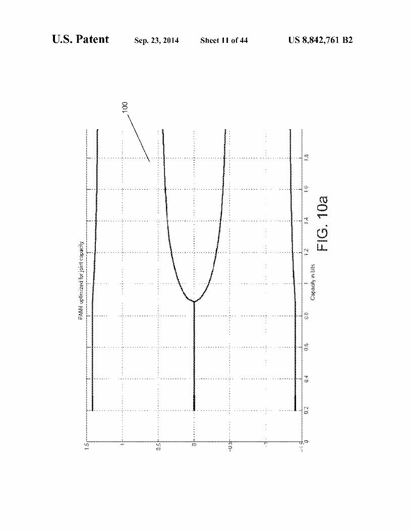
FIGS. 10a-10d are locus plots showing the location of constellation points of a PAM-4 constellation optimized for PD capacity and joint capacity versus user bit rate per dimen-sion and versus SNR.
FIGS. 11a and 11b are design tables of PD capacity and 65
joint capacity optimized PAM-4 constellations in accordance with embodiments of the invention.
4 FIGS. 12a-12d are locus plots showing the location of
constellation points of a PAM-8 constellation optimized for PD capacity and joint capacity versus user bit rate per dimen-sion and versus SNR.
FIGS. 13a and 13b are design tables of PD capacity and joint capacity optimized PAM-8 constellations in accordance with embodiments of the invention.
FIGS. 14a-14d are locus plots showing the location of constellation points of a PAM-16 constellation optimized for PD capacity and joint capacity versus user bit rate per dimen-sion and versus SNR.
FIGS. 15a and 15b are design tables of PD capacity and joint capacity optimized PAM-16 constellations in accor-dance with embodiments of the invention.
FIGS. 16a-16d are locus plots showing the location of constellation points of a PAM-32 constellation optimized for PD capacity and joint capacity versus user bit rate per dimen-sion and versus SNR.
FIGS. 17a and 17b are design tables of PD capacity and joint capacity optimized PAM-32 constellations in accor-dance with embodiments of the invention.
FIG. 18 is a chart showing the SNR gap to Gaussian capac-ity for traditional and capacity optimized PSK constellations.
FIG. 19 is a chart showing the location of constellation points of PD capacity optimized PSK-32 constellations.
FIG. 20 is a series of PSK-32 constellations optimized for PD capacity at different SNRs in accordance with embodi-ments of the invention.
FIG. 21 illustrates a QAM-64 constructed from orthogonal Cartesian product of two PD optimized PAM-8 constellations in accordance with an embodiment of the invention.
FIGS. 22a and 22b are locus plots showing the location of constellation points of a PAM-4 constellation optimized for PD capacity over a fading channel versus user bit rate per dimension and versus SNR.
FIGS. 23a and 23b are locus plots showing the location of constellation points of a PAM-8 constellation optimized for PD capacity over a fading channel versus user bit rate per dimension and versus SNR.
FIGS. 24a and 24b are locus plots showing the location of constellation points of a PAM-16 constellation optimized for PD capacity over a fading channel versus user bit rate per dimension and versus SNR.
DETAILED DESCRIPTION OF THE INVENTION
Turning now to the drawings, communication systems in accordance with embodiments of the invention are described that use signal constellations, which have unequally spaced (i.e. `geometrically' shaped) points. In several embodiments, the locations of geometrically shaped points are designed to provide a given capacity measure at a reduced signal-to-noise ratio (SNR) compared to the SNR required by a constellation that maximizes d_,,,. In many embodiments, the constella-tions are selected to provide increased capacity at a predeter-mined range of channel signal-to-noise ratios (SNR). Capac-ity measures that can be used in the selection of the location of constellation points include, but are not limited to, parallel decode (PD) capacity and joint capacity.
In many embodiments, the communication systems utilize capacity approaching codes including, but not limited to, LDPC and Turbo codes. As is discussed further below, direct optimization of the constellation points of a communication system utilizing a capacity approaching channel code, can yield different constellations depending on the SNR for which they are optimized. Therefore, the same constellation is unlikely to achieve the same coding gains applied across all

US 8,842,761 B2 5
code rates; that is, the same constellation will not enable the best possible performance across all rates. In many instances, a constellation at one code rate can achieve gains that cannot be achieved at another code rate. Processes for selecting capacity optimized constellations to achieve increased cod-ing gains based upon a specific coding rate in accordance with embodiments of the invention are described below. In a num-ber of embodiments, the communication systems can adapt location of points in a constellation in response to channel conditions, changes in code rate and/or to change the target user data rate. Communication Systems
A communication system in accordance with an embodi-ment of the invention is shown in FIG. 1. The communication system 10 includes a source 12 that provides user bits to a transmitter 14. The transmitter transmits symbols over a channel to a receiver 16 using a predetermined modulation scheme. The receiver uses knowledge of the modulation scheme, to decode the signal received from the transmitter. The decoded bits are provided to a sink device that is con-nected to the receiver.
A transmitter in accordance with an embodiment of the invention is shown in FIG. 2. The transmitter 14 includes a coder 20 that receives user bits from a source and encodes the bits in accordance with a predetermined coding scheme. In a number of embodiments, a capacity approaching code such as a turbo code or a LDPC code is used. In other embodiments, other coding schemes can be used to providing a coding gain within the communication system. A mapper 22 is connected to the coder. The mapper maps the bits output by the coder to a symbol within a geometrically distributed signal constella-tion stored within the mapper. The mapper provides the sym-bols to a modulator 24, which modulates the symbols for transmission via the channel.
A receiver in accordance with an embodiment of the inven-tion is illustrated in FIG. 3. The receiver 16 includes a demodulator 30 that demodulates a signal received via the channel to obtain symbol or bit likelihoods. The demapper uses knowledge of the geometrically shaped symbol constel-lation used by the transmitter to determine these likelihoods. The demapper 32 provides the likelihoods to a decoder 34 that decodes the encoded bit stream to provide a sequence of received bits to a sink. Geometrically Shaped Constellations
Transmitters and receivers in accordance with embodi-ments of the invention utilize geometrically shaped symbol constellations. In several embodiments, a geometrically shaped symbol constellation is used that optimizes the capac-ity of the constellation. Various geometrically shaped symbol constellations that can be used in accordance with embodi-ments of the invention, techniques for deriving geometrically shaped symbol constellations are described below. Selection of a Geometrically Shaped Constellation
Selection of a geometrically shaped constellation for use in a communication system in accordance with an embodiment of the invention can depend upon a variety of factors includ-ing whether the code rate is fixed. In many embodiments, a geometrically shaped constellation is used to replace a con-ventional constellation (i.e. a constellation maximized for dm ,„) in the mapper of transmitters and the demapper of receivers within a communication system. Upgrading a com-munication system involves selection of a constellation and in many instances the upgrade can be achieved via a simple firmware upgrade. In other embodiments, a geometrically shaped constellation is selected in conjunction with a code rate to meet specific performance requirements, which can for example include such factors as a specified bit rate, a maxi-
6 mum transmit power. Processes for selecting a geometric constellation when upgrading existing communication sys-tems and when designing new communication systems are discussed further below.
5 Upgrading Existing Communication Systems A geometrically shaped constellation that provides a
capacity, which is greater than the capacity of a constellation maximized for d_,,, can be used in place of a conventional constellation in a communication system in accordance with
io embodiments of the invention. In many instances, the substi-tution of the geometrically shaped constellation can be achieved by a firmware or software upgrade of the transmit-ters and receivers within the communication system. Not all geometrically shaped constellations have greater capacity
15 than that of a constellation maximized for d_,,. One approach to selecting a geometrically shaped constellation having a greater capacity than that of a constellation maximized for d_,, is to optimize the shape of the constellation with respect to a measure of the capacity of the constellation for a given
20 SNR. Capacity measures that can be used in the optimization process can include, but are not limited to, joint capacity or parallel decoding capacity. Joint Capacity and Parallel Decoding Capacity
A constellation can be parameterized by the total number 25 of constellation points, M, andthe numberof real dimensions,
N,_. In systems where there are no belief propagation itera-tions between the decoder and the constellation demapper, the constellation demapper can be thought of as part of the channel. A diagram conceptually illustrating the portions of a
30 communication system that can be considered part of the channel for the purpose of determining PD capacity is shown in FIG. 4a. The portions of the communication system that are considered part of the channel are indicated by the ghost line 40. The capacity of the channel defined as such is the parallel
35 decoding (PD) capacity, given by:
-,
=o 40
where X, is the ith bit of the I-bits transmitted symbol, andY is the received symbol, and I(A;B) denotes the mutual infor-mation between random variables A and B.
45 Expressed anotherway, the PD capacity of a channel can be viewed in terms of the mutual information between the output bits of the encoder (such as an LDPC encoder) at the trans-mitter and the likelihoods computed by the demapper at the receiver. The PD capacity is influenced by both the placement
50 of points within the constellation and by the labeling assign-ments.
With belief propagation iterations between the demapper and the decoder, the demapper can no longer be viewed as part of the channel, and the joint capacity of the constellation
55 becomes the tightest known bound on the system perfor-mance. A diagram conceptually illustrating the portions of a communication system that are considered part of the channel for the purpose of determining the j oint capacity of a constel-lation is shown in FIG. 4b. The portions of the communica-
60 tion system that are considered part of the channel are indi-cated by the ghost line 42. The joint capacity of the channel is given by:
C-70INT AX1 . ))
65 Joint capacity is a description of the achievable capacity between the input of the mapper on the transmit side of the link and the output of the channel (including for example

US 8,842,761 B2 7
8 AWGN and Fading channels). Practical systems must often
SNR„ have converged, the capacity measure of the constel-
`demap' channel observations prior to decoding. In general, lation has been optimized. As is explained in more detail the step causes some loss of capacity. In fact it can be proven
below, capacity optimized constellation at low SNRs are geo-
that C,>_C,,,,,aCPD . That is, C,,,,,T upper bounds the metrically shaped constellations that can achieve signifi- capacity achievable by C D . The methods of the present 5 cantly higher performance gains (measured as reduction in invention are motivated by considering the fact that practical
minimum required SNR) than constellations that maximize
limits to a given communication system capacity are limited
dm by C,,,,, and C D . In several embodiments of the invention, The process illustrated in FIG. 5 can maximize PD capacity geometrically shaped constellations are selected that maxi- or joint capacity of an M-ary constellation for a given SNR. mize these measures. io Although the process illustrated in FIG. 5 shows selecting an Selecting a Constellation Having an Optimal Capacity
M-ary constellation optimized for capacity, a similar process
Geometrically shaped constellations in accordance with
could be used that terminates upon generation of an M-ary embodiments of the invention can be designed to optimize constellation where the SNR gap to Gaussian capacity at a capacity measures including, but not limited to PD capacity given capacity is a predetermined margin lower than the SNR or j oint capacity. A process for selecting the points, and poten- 15 gap of a conventional constellation, for example 0.5 db. Alter- tially the labeling, of a geometrically shaped constellation for natively, other processes that identify M-ary constellations use in a communication system having a fixed code rate in
having capacity greater than the capacity of a conventional
accordance with an embodiment of the invention is shown in constellation can be used in accordance with embodiments of FIG. 5. The process 50 commences with the selection (52) of
the invention. A geometrically shaped constellation in accor-
an appropriate constellation size M and a desired capacity per 2o dance with embodiments of the invention can achieve greater dimension q. In the illustrated embodiment, the process capacity than the capacity of a constellation that maximizes involves a check (52) to ensure that the constellation size can
dm in without having the optimal capacity for the SNR range
support the desired capacity. In the event that the constellation within which the communication system operates. size could support the desired capacity, then the process itera- We note that constellations designed to maximize joint tively optimizes the M-ary constellation for the specified 25 capacity may also be particularly well suited to codes with capacity. Optimizing a constellation for a specified capacity symbols over GF(q), or with multi-stage decoding. Con- often involves an iterative process, because the optimal con- versely constellations optimized for PD capacity could be stellation depends upon the SNR at which the communication
better suited to the more common case of codes with symbols
system operates. The SNR for the optimal constellation to over GF(2) give a required capacity is not known a priori. Throughout the so Optimizing the Capacity of an M-Ary Constellation at a description of the present invention SNR is defined as the
Given SNR
ratio of the average constellation energy per dimension to the
Processes for obtaining a capacity optimized constellation average noise energy per dimension. In most cases the capac- often involve determining the optimum location for the points ity can be set to equal the target user bit rate per symbol per of an M-ary constellation at a given SNR. An optimization dimension. In some cases adding some implementation mar- 35 process, such as the optimization process 56 shown in FIG. 5, gin on top of the target user bit rate could result in a practical
typically involves unconstrained or constrained non-linear
system that can provide the required user rate at a lower rate. optimization. Possible objective functions to be maximized The margin is code dependent. The following procedure are the Joint or PD capacity functions. These functions may could be used to determine the target capacity that includes
be targeted to channels including but not limited to Additive
some margin on top of the user rate. First, the code (e.g. LDPC 40 White Gaussian Noise (AWGN) or Rayleigh fading channels. or Turbo) can be simulated in conjunction with a conventional
The optimization process gives the location of each constel-
equally spaced constellation. Second, from the simulation
lation point identified by its symbol labeling. In the case results the actual SNR of operation at the required error rate where the objective is joint capacity, point bit labelings are can be found. Third, the capacity of the conventional constel- irrelevant meaning that changing the bit labelings doesn't lation at that SNR can be computed. Finally, a geometrically 45 change the joint capacity as long as the set of point locations shaped constellation can be optimized for that capacity. remains unchanged.
In the illustrated embodiment, the iterative optimization
The optimization process typically finds the constellation loop involves selecting an initial estimate of the SNR at which
that gives the largest PD capacity or joint capacity at a given
the system is likely to operate (i.e. SNR,,). In several embodi- SNR. The optimization process itself often involves an itera- ments the initial estimate is the SNR required using a con- 50 tive numerical process that among other things considers ventional constellation. In other embodiments, other tech- several constellations and selects the constellation that gives niques can be used for selecting the initial SNR. An M-ary the highest capacity at a given SNR. In other embodiments, constellation is then obtained by optimizing (56) the constel- the constellation that requires the least SNR to give a required lation to maximize a selected capacity measure at the initial
PD capacity or joint capacity can also be found. This requires
SNR„ estimate. Various techniques for obtaining an opti- 55 running the optimization process iteratively as shown in FIG. mized constellation for a given SNR estimate are discussed
5.
below. Optimization constraints on the constellation point loca- The SNR at which the optimized M-ary constellation pro- tions may include, but are not limited to, lower and upper
vides the desired capacity per dimension rl (SNR,,,) is deter- bounds on point location, peak to average power of the result- mined (57). A determination (58) is made as to whether the 60 ing constellation, and zero mean in the resulting constella- SNR,,, and SNR,, have converged. In the illustrated embodi- tion. It can be easily shown that a globally optimal constella- ment convergence is indicated by SNR,,, equaling SNR,,. In tion will have zero mean (no DC component). Explicit a number of embodiments, convergence can be determined
inclusion of a zero mean constraint helps the optimization
based upon the difference between SNR,,, and SNR,, being routine to converge more rapidly. Except for cases where less than a predetermined threshold. When SNR, and SNR,, 65 exhaustive search of all combinations of point locations and have not converged, the process performs another iteration
labelings is possible it will not necessarily always be the case
selecting SNR,,, as the new SNR„ (55). When SNR, and
that solutions are provably globally optimal. In cases where

US 8,842,761 B2 9
10 exhaustive search is possible, the solution provided by the non-linear optimizer is in fact globally optimal.
The processes described above provide examples of the manner in which a geometrically shaped constellation having an increased capacity relative to a conventional capacity can be obtained for use in a communication system having a fixed code rate and modulation scheme. The actual gains achiev-able using constellations that are optimized for capacity com-pared to conventional constellations that maximize d m ,„ are considered below. Gains Achieved by Optimized Geometrically Spaced Con-stellations
The ultimate theoretical capacity achievable by any com-munication method is thought to be the Gaussian capacity, C, which is defined as:
CG = Zlo g2(1 +SNR)
Where signal-to-noise (SNR) is theratio of expected signal power to expected noise power. The gap thatremains between the capacity of a constellation and C G can be considered a measure of the quality of a given constellation design.
The gap in capacity between a conventional modulation scheme in combination with a theoretically optimal coder can be observed with reference to FIGS. 6a and 6b. FIG. 6a includes a chart 60 showing a comparison between Gaussian capacity and the PD capacity of conventional PAM-2,4, 8,16, and 32 constellations that maximize d_,,,, Gaps 62 exist between the plot of Gaussian capacity and the PD capacity of the various PAM constellations. FIG. 6b includes a chart 64 showing a comparison between Gaussian capacity and the joint capacity of conventional PAM-2, 4, 8, 16, and 32 con-stellations that maximize d_,,,, Gaps 66 exist between the plot of Gaussian capacity and the joint capacity of the various PAM constellations. These gaps in capacity represent the extent to which conventional PAM constellations fall short of obtaining the ultimate theoretical capacity i.e. the Gaussian capacity.
In order to gain a better view of the differences between the curves shown in FIGS. 6a and 6b at points close to the Gaus-sian capacity, the SNR gap to Gaussian capacity for different values of capacity for each constellation are plotted in FIG. 7. It is interesting to note from the chart 70 in FIG. 7 that (unlike the joint capacity) at the same SNR, the PD capacity does not necessarily increase with the number of constellation points. As is discussed further below, this is not the case with PAM constellations optimized for PD capacity.
FIGS. 8a and 8b summarize performance of constellations for PAM-4, 8, 16, and 32 optimized for PD capacity and joint capacity (it should be noted that BPSK is the optimal PAM-2 constellation at all code rates). The constellations are opti-mized for PD capacity and joint capacity for different target user bits per dimension (i.e. code rates). The optimized con-stellations are different depending on the target user bits per dimension, and also depending on whether they have been designed to maximize the PD capacity or the joint capacity. All the PD optimized PAM constellations are labeled using a gray labeling which is not always the binary reflective gray labeling. It should be noted that not all gray labels achieve the maximum possible PD capacity even given the freedom to place the constellation points anywhere on the real line. FIG. 8a shows the SNR gap for each constellation optimized for PD capacity. FIG. 8b shows the SNR gap to Gaussian capac-ity for each constellation optimized for joint capacity. Again, it should be emphasized that each `+' on the plot represents a different constellation.
Referring to FIG. 8a, the coding gain achieved using a constellation optimized for PD capacity can be appreciated by comparing the SNR gap at a user bit rate per dimension of 2.5 bits for PAM-32. A user bit rate per dimension of 2.5 bits
5 for a system transmitting 5 bits per symbol constitutes a code rate of/2. At that code rate the constellation optimized for PD capacity provides an additional coding gain of approximately 1.5 dB when compared to the conventional PAM-32 constel-lation.
10 The SNR gains that can be achieved using constellations that are optimized for PD capacity can be verified through simulation. The results of a simulation conducted using a rate 1/2 LDPC code in conjunction with a conventional PAM-32 constellation and in conjunction with a PAM-32 constellation
15 optimized for PD capacity are illustrated in FIG. 9. A chart 90 includes plots of Frame Error Rate performance of the differ-ent constellations with respect to SNR and using different length codes (i.e. k=4,096 and k=16,384). Irrespective of the code that is used, the constellation optimized for PD capacity
20 achieves a gain of approximately 1.3 dB, which closely approaches the gain predicted from FIG. 8a. Capacity Optimized Pam Constellations
Using the processes outlined above, locus plots of PAM constellations optimized for capacity can be generated that
25 show the location of points within PAM constellations versus SNR. Locus plots of PAM-4, 8, 16, and 32 constellations optimized for PD capacity and joint capacity and correspond-ing design tables at various typical user bit rates per dimen-sion are illustrated in FIGS. 10a-17b. The locus plots and
3o design tables show PAM-4,8,16,32 constellation point loca-tions and labelings from low to high SNR corresponding to a range of low to high spectral efficiency.
In FIG. 10a, a locus plot 100 shows the location of the points of PAM-4 constellations optimized for Joint capacity
35 plotted against achieved capacity. A similar locus plot 105 showing the location of the points of Joint capacity optimized PAM-4 constellations plotted against SNR is included in FIG. 10b. In FIG. 10c. the location of points for PAM-4 optimized for PD capacity is plotted against achievable capacity and in
4o FIG. 10d the location of points for PAM-4 for PD capacity is plotted against SNR. At low SNRs, the PD capacity optimized PAM-4 constellations have only 2 unique points, while the Joint optimized constellations have 3. As SNR is increased, each optimization eventually provides 4 unique points. This
45 phenomenon is explicitly described in FIG. 1la and FIG. 1lb where vertical slices of FIGS. 10ab and 10cd are captured in tables describing some PAM-4 constellations designs of interest. The SNR slices selected represent designs that achieve capacities={0.5, 0.75, 1.0, 1.25, 1.51 bits per symbol
50 (bps). Given that PAM-4 can provide at most 1092(4)2 bps, these design points represent systems with information code rates R={'/4 3/R '/z 5/8 3/41 respectively.
FIGS. 12ab and 12cd present locus plots of PD capacity and joint capacity optimized PAM-8 constellation points ver-
55 sus achievable capacity and SNR. FIGS. Da and 13b provide slices from these plots at SNRs corresponding to achievable capacities ,1={0.5, 1.0, 1.5, 2.0, 2.51 bps. Each of these slices correspond to systems with code rate R --q bp S/1092(8), result- ing in R={'/6, 1/3, '/2, 2/3, 5/61. As an example of the relative performance of the constellations in these tables, consider
60 FIG. 13b which shows a PD capacity optimized PAM-8 con- stellation optimized for SNR=9.00 dB, or 1.5 bps. We next examine the plot provided in FIG. 8a and see that the gap of the optimized constellation to the ultimate, Gaussian, capac- ity (CG) is approximately 0.5 dB. At the same spectral effi-
65 ciency, the gap of the traditional PAM-8 constellation is approximately 1.0 dB. The advantage of the optimized con- stellation is 0.5 dB for the same rate (in this case R 'h). This

US 8,842,761 B2 11
gain can be obtained by only changing the mapper and demapper in the communication system and leaving all other blocks the same.
Similar information is presented in FIGS. 14abcd, and 15ab which provide loci plots and design tables for PAM-16 PD capacity and joint capacity optimized constellations. Likewise FIGS. 16abcd, 17ab provide loci plots and design tables for PAM-32 PD capacity and joint capacity optimized constellations. Capacity Optimized PSK Constellations
Traditional phase shift keyed (PSK) constellations are already quite optimal. This can be seen in the chart 180 comparing the SNR gaps of tradition PSK with capacity optimized PSK constellations shown in FIG. 18 where the gap between PD capacity and Gaussian capacity is plotted for traditional PSK-4,8,16,32 and for PD capacity optimized PSK-4,8,16,32.
The locus plot of PD optimized PSK-32 points across SNR is shown in FIG. 19, which actually characterizes all PSKs with spectral efficiency q:55. This can be seen in FIG. 20. Note that at low SNR (0.4 dB) the optimal PSK-32 design is the same as traditional PSK-4, at SNR=8.4 dB optimal PSK-32 is the same as traditional PSK-8, at SNR=14.8 dB optimal PSK-32 is the same as traditional PSK-16, and finally at SNRs greater than 20.4 dB optimized PSK-32 is the same as traditional PSK-32. There are SNRs between these discrete points (for instance SNR-2 and 15. dB) for which optimized PSK-32 provides superior PD capacity when compared to traditional PSK constellations.
We note now that the locus of points for PD optimized PSK-32 in FIG. 19 in conjunction with the gap to Gaussian capacity curve for optimized PSK-32 in FIG. 18 implies a potential design methodology. Specifically, the designer could achieve performance equivalent or better than that enabled by traditional PSK-4,8,16 by using only the opti-mized PSK-32 in conjunction with a single tuning parameter that controlled where the constellation points should be selected from on the locus of FIG. 19. Such an approach would couple a highly rate adaptive channel code that could vary its rate, for instance, rate 4/5 to achieve and overall (code plus optimized PSK-32 modulation) spectral efficiency of 4 bits per symbol, down to '/5 to achieve an overall spectral efficiency of I bit per symbol. Such an adaptive modulation and coding system could essentially perform on the optimal continuum represented by the rightmost contour of FIG. 18. Adaptive Rate Design
In the previous example spectrally adaptive use of PSK-32 was described. Techniques similar to this can be applied for other capacity optimized constellations across the link between a transmitter and receiver. For instance, in the case where a system implements quality of service it is possible to instruct a transmitter to increase or decrease spectral effi-ciency on demand. In the context of the current invention a capacity optimized constellation designed precisely for the target spectral efficiency can be loaded into the transmit map-per in conjunction with a code rate selection that meets the end user rate goal. When such a modulation/code rate change occurred a message could propagated to the receiver so that the receiver, in anticipation of the change, could select a demapper/decoder configuration in order to match the new transmit-side configuration.
Conversely, the receiver could implement a quality of per-formance based optimized constellation/code rate pair con-trol mechanism. Such an approach would include some form of receiver quality measure. This could be the receiver's estimate of SNR or bit error rate. Take for example the case where bit error rate was above some acceptable threshold. In
12 this case, via a backchannel, the receiver could request that the transmitter lower the spectral efficiency of the link by swapping to an alternate capacity optimized constellation/ code rate pair in the coder and mapper modules and then
5 signaling the receiver to swap in the complementary pairing in the demapper/decoder modules. Geometrically Shaped QAM Constellations
Quadrature amplitude modulation (QAM) constellations can be constructed by orthogonalizing PAM constellations
10 into QAM inphase and quadrature components. Constella-tions constructed in this way can be attractive in many appli-cations because they have low-complexity demappers.
In FIG. 21 we provide an example of a Quadrature Ampli- 15 tude Modulation constellation constructed from a Pulse
Amplitude Modulation constellation. The illustrated embodi-ment was constructed using a PAM-8 constellation optimized for PD capacity at user bit rate per dimension of 1.5 bits (corresponds to an SNR of 9.0 dB) (see FIG. 13b). The label-
20 point pairs in this PAM-8 constellation are {(000, —1.72), (001, —0.81), (010, 1.72), (011, —0.62), (100, 0.62), (101, 0.02), (110, 0.81), (111, —0.02)}. Examination of FIG. 21 shows thatthe QAM constellation construction is achievedby replicating a complete set of PAM-8 points in the quadrature
25 dimension for each of the 8 PAM-8 points in the in-phase dimension. Labeling is achieved by assigning the PAM-8 labels to the LSB range on the in-phase dimension and to the MSB range on the quadrature dimension. The resulting 8x8 outer product forms a highly structured QAM-64 for which
30 very low-complexity de-mappers can be constructed. Due to the orthogonality of the in-phase and quadrature components the capacity characteristics of the resulting QAM-64 constel-lation are identical to that of the PAM-8 constellation on a per-dimension basis.
35 N-Dimensional Constellation Optimization Rather than designing constellations in I-D (PAM for
instance) and then extending to 2-D (QAM), it is possible to take direct advantage in the optimization step of the addi-tional degree of freedom presented by an extra spatial dimen-
40 sion. In general it is possible to design N-dimensional con-stellations and associated labelings. The complexity of the optimization step grows exponentially in the number of dimensions as does the complexity of the resulting receiver de-mapper. Such constructions constitute embodiments of
45 the invention and simply require more `run-time' to produce. Capacity Optimized Constellations for Fading Channels
Similar processes to those outlined above can be used to design capacity optimized constellations for fading channels in accordance with embodiments of the invention. The pro-
50 cesses are essentially the same with the exception that the manner in which capacity is calculated is modified to account for the fading channel. A fading channel can be described using the following equation:
55 P a(t).X+N
where X is the transmitted signal, N is an additive white Gaussian noise signal and a(t) is the fading distribution, which is a function of time.
In the case of a fading channel, the instantaneous SNR at 60 the receiver changes according to a fading distribution. The
fading distribution is Rayleigh and has the property that the average SNR of the system remains the same as in the case of the AWGN channel, E[X 2]/E[N2]. Therefore, the capacity of the fading channel can be computed by taking the expectation
65 of AWGN capacity, at a given average SNR, over the Ray-leigh fading distribution of a that drives the distribution of the instantaneous SNR.

US 8,842,761 B2 13
Many fading channels follow a Rayleigh distribution. FIGS. 22a-24b are locus plots of PAM -4, 8, and 16 constel-lations that have been optimized for PD capacity on a Ray-leigh fading channel. Locus plots versus user bit rate per dimension and versus SNR are provided. Similar processes 5
can be used to obtain capacity optimized constellations that are optimized using other capacity measures, such as joint capacity, and/or using different modulation schemes.
What is claimed is: 1. A digital communication system, comprising: 10
a transmitter configured to transmit signals to a receiver via a communication channel;
wherein the transmitter, comprises: • coder configured to receive user bits and output
encoded bits at an expanded output encoded bit rate 15
using an LDPC code; • mapper configured to map encoded bits to symbols in
a QAM symbol constellation; • modulator configured to generate a signal for transmis-
sion via the communication channel using symbols 20
generated by the mapper; and wherein the QAM symbol constellation is a geometri-
cally spaced symbol constellation optimized for capacity using parallel decode capacity that provides a given capacity at a reduced signal-to-noise ratio 25
compared to a QAM signal constellation that maxi-mizes d_,
2. The communication system of claim 1, wherein the geometrically spaced symbol constellation is capacity opti-mized subject to additional constraints. 30
3. The communication system of claim 1, wherein the channel is an AWGN channel.
4. The communication system of claim 1, wherein the channel is a fading channel.
5. The communication system of claim 1, wherein the 35
QAM constellation is a QAM-64 constellation. 6. The communication system of claim 5, wherein the
LDPC code is a rate 1/2 LDPC code. 7. The communication system of claim 6, wherein the
symbol constellation is formed using a PAM -8 constellation 40
comprising the set of constellation points 1-1.72, —0.81,1.72, —0.62, 0.62, 0.02, 0.81, —0.021.
8. The communication system of claim 5, wherein the LDPC code is a rate 2/3 LDPC code.
9. The communication system of claim 8, wherein the 45
symbol constellation is formed using a PAM -8 constellation comprising the set of constellation points 1-1.64, —0.97,1.64, —0.58, 0.58, 0.15, 0.97, —0.151.
10. The communication system of claim 5, wherein the LDPC code is a rate 5/6 LDPC code. 50
11. The communication system of claim 10, wherein the symbol constellation is formed using a PAM -8 constellation comprising the set of constellation points 1-1.60, —1.03, —0.19, —0.58, 1.60, 1.03, 0.19, 0.581.
12. The communication system of claim 1, wherein the 55
QAM constellation is a QAM-256 constellation. 13. The communication system of claim 12, wherein the
LDPC code is a rate 1/2 LDPC code. 14. The communication system of claim 13, wherein the
symbol constellation is formed using a PAM-16 constellation 60
comprising the set of constellation points {- 1.98, —1.29,1.94, —1.17, —0.38, —0.65, —0.38, —0.68, 1.09, 0.76, 1.26, 0.76, 0.06, 0.29, 0.06, 0.291.
15. The communication system of claim 12, wherein the LDPC code is a rate 3/4 LDPC code. 65
16. The communication system of claim 15, wherein the symbol constellation is formed using a PAM-16 constellation
14 comprising the set of constellation points {- 1.84, —1.42,1.84, —1.11, —0.40, —0.65, —0.29, —0.83, 1.11, 0.84, 1.42, 0.65, 0.05, 0.29, —0.05, 0.401.
17. A digital communication system, comprising: a receiver configured to receive signals transmitted via a
communication channel using a QAM symbol constel- lation;
wherein the receiver, comprises: • demodulator configured to demodulate the signal
received via the communication channel; • demapper configured to estimate likelihoods of sym-
bols in a QAM symbol constellation from the demodulated signal;
• decoder that is configured to estimate decoded bits from the likelihoods generated by the demapper using an LDPC code; and
wherein the QAM symbol constellation is a geometri-cally spaced symbol constellation optimized for capacity using parallel decode capacity that provides a given capacity at a reduced signal-to-noise ratio compared to a QAM signal constellation that maxi-mizes d_,
18. The communication system of claim 17, wherein the geometrically spaced symbol constellation is capacity opti-mized subject to additional constraints.
19. The communication system of claim 17, wherein the channel is an AWGN channel.
20. The communication system of claim 17, wherein the channel is a fading channel.
21. The communication system of claim 17, wherein the QAM constellation is a QAM-64 constellation.
22. The communication system of claim 21, wherein the LDPC code is a rate 1/2 LDPC code.
23. The communication system of claim 22, wherein the symbol constellation is formed using a PAM -8 constellation comprising the set of constellation points 1-1.72, —0.81,1.72, —0.62, 0.62, 0.02, 0.81, —0.021.
24. The communication system of claim 21, wherein the LDPC code is a rate 2/3 LDPC code.
25. The communication system of claim 24, wherein the symbol constellation is formed using a PAM -8 constellation comprising the set of constellation points 1-1.64, —0.97,1.64, —0.58, 0.58, 0.15, 0.97, —0.151.
26. The communication system of claim 21, wherein the LDPC code is a rate 5/6 LDPC code.
27. The communication system of claim 26, wherein the symbol constellation is formed using a PAM -8 constellation comprising the set of constellation points 1-1.60, —1.03, —0.19, —0.58, 1.60, 1.03, 0.19, 0.581.
28. The communication system of claim 17, wherein the QAM constellation is a QAM-256 constellation.
29. The communication system of claim 28, wherein the LDPC code is a rate 1/2 LDPC code.
30. The communication system of claim 29, wherein the symbol constellation is formed using a PAM-16 constellation comprising the set of constellation points 1-1.98, —1.29,1.94, —1.17, —0.38, —0.65, —0.38, —0.68, 1.09, 0.76, 1.26, 0.76, 0.06, 0.29, 0.06, 0.291.
31. The communication system of claim 28, wherein the LDPC code is a rate 3/4 LDPC code.
32. The communication system of claim 31, wherein the symbol constellation is formed using a PAM-16 constellation comprising the set of constellation points 1-1.84, —1.42,1.84, —1.11, —0.40, —0.65, —0.29, —0.83, 1.11, 0.84, 1.42, 0.65, 0.05, 0.29, —0.05, 0.401.