u.s. environmental protection agency. environmental protection agency ... 1.1 background ... if the...
TRANSCRIPT


Revision 0 -11/07/01
U.S. Environmental Protection Agency
Environmental Technology Verification Program
For Metal Finishing Pollution Prevention Technologies
Verification Test Plan
Evaluation of KCH Services, Inc. Automated Covered Tank System for Energy Conservation (ACTSEC)
Revision 0
November 7, 2001
Concurrent Technologies Corporation is the Verification Partner for the EPA ETV Metal Finishing Pollution Prevention Technologies Center under EPA Cooperative
Agreement No. CR826492-01-0.

Revision 0 – 11/07/01
U.S. Environmental Protection Agency
Environmental Technology Verification Program
For Metal Finishing Pollution Prevention Technologies
Verification Test Plan
Evaluation of KCH Services, Inc. Automated Covered Tank System for Energy Conservation (ACTSEC)
Revision 0
November 7, 2001
i

Revision 0 – 11/07/01
TITLE: Environmental Technology Verification Program for Metal Finishing Pollution Prevention Technologies Verification Test Plan for the Evaluation of KCH Services, Inc. Automated Covered Tank System for Energy Conservation (ACTSEC).
ISSUE DATE: November 7, 2001
DOCUMENT CONTROL
This document will be maintained by Concurrent Technologies Corporation (CTC) in accordance with the EPA Environmental Technology Verification Program Quality and Management Plan for the Pilot Period 1995–2001 (EPA/600/R-98/064). Document control elements include unique issue numbers, document identification, numbered pages, document distribution records, tracking of revisions, a document MASTER filing and retrieval system, and a document archiving system.
ACKNOWLEDGMENT
This is to acknowledge Joe Candio, Rick Hall, Tom Lopresti, P.E., David Allen, Jim Totter, Marvin South, and Valerie Whitman for their help in preparing this document.
Concurrent Technologies Corporation is the Verification Partner for the EPA ETV Metal Finishing Pollution Prevention Technologies Center under EPA Cooperative
Agreement No. CR826492-01-0.
ii

Revision 0 – 11/07/01
Environmental Technology Verification Program for Metal Finishing Pollution Prevention Technologies Verification Test Plan for the Evaluation of KCH Services, Inc. Automated
Covered Tank System for Energy Conservation (ACTSEC).
PREPARED BY:
APPROVED BY:
Signature denotes acceptance of this test plan as written regarding experimental design, quality assurance, test and analysis methods, operational procedures, equipment configuration, project management and current KCH Services, Inc. ACTSEC technology operating effectiveness prior to testing.
iii

Revision 0 – 11/07/01
TABLE OF CONTENTS
Page
1.0 INTRODUCTION............................................................................................................. 1
1.1 Background ............................................................................................................. 1
1.2 Data Quality Objectives (DQO).............................................................................. 3
2.0 TECHNOLOGY DESCRIPTION ................................................................................... 4
2.1 Theory of Operation................................................................................................ 4
2.2 Description of KCH System ................................................................................... 6
2.3 Commercial Status .................................................................................................. 9
2.4 Environmental Significance .................................................................................... 9
2.5 Local Installation..................................................................................................... 9
3.0 EXPERIMENTAL DESIGN.......................................................................................... 10
3.1 Test Goals and Objectives..................................................................................... 10
3.2 Critical and Non-Critical Measurements .............................................................. 10
3.3 Test Matrix............................................................................................................ 10
3.4 Testing and Operating Procedure.......................................................................... 11
3.4.1 Set-up and System Initialization Procedures ............................................ 11
3.4.2 System Operation...................................................................................... 12
3.4.3 Sample Collection and Handling .............................................................. 12
3.4.4 Process Measurements and Information Collection ................................. 12
3.4.4.1 Electrical Power Requirement Test #1.......................................... 12
3.4.4.2 Electrical Power Requirement Test #2.......................................... 13
3.4.4.3 Electrical Power Requirement Test #3.......................................... 13
3.4.4.4 Electrical Power Requirement Test #4.......................................... 13
3.4.4.5 Electrical Power Requirement Test #5.......................................... 14
3.4.4.6 Ventilation Flow Rate Test #6 ...................................................... 14
3.4.4.7 Ventilation Flow Rate Test #7 ...................................................... 15
3.4.4.8 Energy and Cost Data ................................................................... 15
3.5 Analytical Procedures ........................................................................................... 16
4.0 QUALITY ASSURANCE/QUALITY CONTROL REQUIREMENTS .................... 16
4.1 Quality Assurance Objectivies.............................................................................. 16
4.2 Data Reduction, Validation, and Reporting .......................................................... 16
iv

Revision 0 – 11/07/01
4.2.1 Internal Quality Control Checks ............................................................... 16
4.2.2 Calculation of Data Quality Indicators ..................................................... 17
4.2.2.1 Precision........................................................................................ 18
4.2.2.2 Accuracy ....................................................................................... 18
4.2.2.3 Completeness ................................................................................ 19
4.2.2.4 Comparability................................................................................ 19
4.2.2.5 Representativeness........................................................................ 19
4.2.3 Other Calculations ..................................................................................... 20
4.2.3.1 Energy and Cost Savings .............................................................. 20
4.2.3.2 Environmental Benefit/Credit ....................................................... 23
4.3 Quality Audits....................................................................................................... 24
5.0 PROJECT MANAGEMENT......................................................................................... 24
5.1 Organization/Personnel Responsibilities .............................................................. 24
5.2 Test Plan Modifications ........................................................................................ 24
6.0 EQUIPMENT AND UTILITY REQUIREMENTS .................................................... 25
7.0 ENVIRONMENTAL SAFETY AND HEALTH (ES&H) REQUIREMENTS ......... 25
7.1 Hazard Communication ........................................................................................ 25
7.2 Emergency Response Plan.................................................................................... 25
7.3 Hazard Controls and Personal Protective Equipment ........................................... 25
7.4 Lockout/Tagout Program...................................................................................... 26
7.5 Material Storage .................................................................................................... 26
7.6 Safe Handling Procedures ..................................................................................... 26
8.0 WASTE MANAGEMENT............................................................................................. 26
9.0 TRAINING ...................................................................................................................... 26
10.0 REFERENCES ................................................................................................................ 27
11.0 DISTRIBUTION ............................................................................................................. 28
v

Revision 0 – 11/07/01
LIST OF FIGURES
Figure 1. Landing Gear .................................................................................................................. 2
Figure 2. KCH ACTSEC Technology at Goodrich ....................................................................... 3
Figure 3. Vented Tanks with Covers ............................................................................................. 4
Figure 4. Diagram of Vented Tanks............................................................................................... 5
Figure 5. Ductwork for Exhaust System........................................................................................ 6
Figure 6. KCH ACTSEC Electrical Control Cabinet .................................................................... 7
LIST OF TABLES
Table 1. Tank Volume & Contents ................................................................................................ 5
Table 2. Goodrich Titanium Wash and Etch LineVentilation ....................................................... 9
Table 3. Test Matrix ..................................................................................................................... 11
Table 4. Test Objectives and Related Test Measurements........................................................... 11
Table 5. QA Objectives................................................................................................................ 16
Table 6. Reliable Power Meter 1600 Tolerances ......................................................................... 18
Table 7. Alnor AXD MicroManometer Tolerances ..................................................................... 19
LIST OF APPENDICES
APPENDIX A: Goodrich Aerospace, Landing Gear Division O&M Manual………….. A-1
APPENDIX B: Test Plan Modification Request………………………………………… B-1
APPENDIX C: ETV-MF Operation Planning Checklist………………………………... C-1
APPENDIX D: Job Training Analysis Form……………………………………………. D-1
APPENDIX E: ETV-MF Project Training Attendance Form…………………………… E-1
APPENDIX F: Field Data Collection Worksheet………………………………………. F-1
vi

Revision 0 – 11/07/01
ACRONYMS & ABREVIATIONS
�C Degrees Celsius �F Degrees Fahrenheit ACGIH American Conference of Governmental Industrial Hygienists ACTSEC Automated Covered Tank System for Energy Conservation AMCA Air Movement and Control Association amp Ampere BHP Brake Horsepower CFM Cubic Feet per Minute cm Cubic Meter CS Cost Savings CSA Canadian Standards Institute CTC Concurrent Technologies Corporation DQO Data Quality Objectives EHS Environmental, Health and Safety EPA U.S. Environmental Protection Agency ERP Emergency Response Plan E.S. Energy Saved ES&H Environmental Safety and Health ETV Environmental Technology Verification ETV-MF Environmental Technology Verification Program Metal Finishing
Technologies P2 FCC Federal Communications Commission fpm Feet per Minute fs Full Scale ft Foot ft2 Square Foot gal Gallon GB Gigabyte HP Horsepower hr Hour HV Heating and Ventilation Hz Hertz ID Identification JTA Job Training Analysis kHz Kilohertz kpa Kilopascals kW Kilowatt kWh Kilowatt-hour L Liter MB Megabyte min Minute MSDS Material Safety Data Sheet O&M Operation and Maintenance OSHA Occupational Safety & Health Administration
vii

Revision 0 – 11/07/01
ACRONYMS & ABREVIATIONS (continued)
P Percent Recovery PARCCS Precision, Accuracy, Representativeness, Comparability,
Completeness, Sensitivity PEL Permissible Exposure Limit PLC Programmable Logic Controller POTW Publicly Owned Treatment Works PPE Personal Protective Equipment psi Pounds per Square Inch QA Quality Assurance QC Quality Control QMP Quality Management Plan RMS Root Mean Square SOP Standard Operating Procedure SR Sample Result SSR Spiked Sample Result STEL Short Term Exposure Limit TCS Total Cost Savings TLV Threshold Limit Value TSA Technical Systems Audit TWA Time Weighted Average UL Underwriters Laboratory U.S. United States V Volt VAC Volts Alternating Current VDC Volts Direct Current wg Water Gauge
viii

Revision 0 -11/07/01
1.0 INTRODUCTION
The purpose of this test plan is to document the objectives, procedures, equipment, and other aspects that will be utilized at the Goodrich Aerospace, Landing Gear Division, Tullahoma, Tennessee, facility during the verification testing of the KCH Services, Inc. (KCH) Automated Covered Tank System for Energy Conservation (ACTSEC) Project. This test plan has been prepared in conjunction with the U.S. Environmental Protection Agency’s (EPA’s) Environmental Technology Verification Program for Metal Finishing Pollution Prevention Technology (ETV-MF). The results of the verification test will be documented in a verification report that will provide objective performance data to metal finishers, environmental permitting agencies, and industry consultants.
The objective of this test plan is to verify whether this technology lowers the power consumption compared to a system with open tanks. Goodrich Aerospace, Landing Gear Division, has implemented a plan to reduce both the energy consumed and the employee exposure to contaminants from the washing and acid etching lines.
This project will evaluate the effectiveness of the energy conservation system. Evaluating and verifying the performance of the KCH ACTSEC technology will be accomplished by collecting operational data and electrical and ventilation measurements. The resultant test data will be used to determine the power consumption of the various motors, fans, and immersion heaters associated with the process.
This test plan has been structured on a format developed for ETV-MF projects. This document describes the intended approach and explains testing plans with respect to areas such as test methodology, procedures, parameters, and instrumentation. Also included in this plan are Quality Assurance/Quality Control (QA/QC) requirements of this task that will ensure the accuracy of data, the use of proper data interpretation procedures, and an emphasis on worker health and safety considerations.
1.1 Background
Goodrich Aerospace, Landing Gear Division, is a part of the Goodrich Aerospace Corporation. It has a distinguished history dating back to 1926, when the Cleveland Pneumatic Company, now part of Goodrich, introduced the industry’s first air-oil landing gear strut. Goodrich merged with Menasco in 1999 to become the world’s largest supplier of landing systems. The Tullahoma facility manufactures components for landing gear for various aircraft including Boeing, Lockheed Martin, and Bombardier. The material of choice is aircraft-quality titanium. Titanium is stronger than steel and is considerably lighter. This metal is well suited for this application.
The parts processed on the wash and etch line are designated as 777 Landing Gear Truck Beams. Due to the nature of the use of this part, it is critical that the part be thoroughly checked to ensure that it will not fail in service. The part is washed and etched to aid in checking for cracks and fissures of any size. After the wash and etch process, a dye is applied to the part. The dye helps to more readily identify component cracking as part of the QC process. If the part passes this QC check, it then proceeds to heat treat. After
1

Revision 0 -11/07/01
heat treat, the part is etched again and checked for cracks and fissures that may have developed during the further processing. The first etch removes approximately .001 of an inch of material all over the part. The second etch removes approximately .002 – .003 of an inch. Pictures of the finished product are shown in Figure 1.
Figure 1. Landing Gear
Power is consumed to energize the fans that provide the negative air movement to remove the air contaminants coming from the wash and etch baths. Also, a scrubber fan that moves exhaust through the scrubber consumes power. Additional power is consumed during the opening and closing of the lids over the wash and acid etching baths, to maintain the required temperature of the baths, and to operate the crane utilized to move the parts on racks to and from the various wash and acid etching line baths.
When operating etch process tanks with the lids closed, there is a reduction in the amount of air required to ventilate contaminates given off by process chemicals. This results in a reduction in makeup air required to balance the system. The makeup air reduction results in a smaller fan and lower heating and cooling cost to properly temper the makeup air.
A reduction in the power demand for this operation will result in energy savings and less natural resources used. This type of savings is the primary claim of KCH for their ACTSEC technology, shown in Figure 2.
2

Revision 0 -11/07/01
Figure 2. KCH ACTSEC Technology at Goodrich
The Occupational Safety and Health Administration (OSHA) has specific standards for situations where employees may be exposed to harmful materials. The standard requires that calculations or monitoring be done to ascertain the levels of contaminants that an employee will be exposed to in correlation to an eight-hour typical work shift. If the level of the contaminant is above the Permissible Exposure Limit (PEL), the facility must provide engineering controls such as ventilation, restrict the time the worker is exposed to the contaminant, or provide personal protective equipment (PPE) that will decrease the exposure level to the employee below the PEL. Evaluating the exposure to employees is not the focus of this verification test plan.
Goodrich Aerospace, Landing Gear Division, commissioned an industrial hygiene survey by their insurance carrier, Liberty Mutual. [Ref. 1] Mr. Michael A. Schepige, CIH, CSP, conducted the industrial hygiene survey for the entire facility on March 29, 2001. The survey concluded that the calculated 8-hour time weighted average (TWA) concentrations of airborne contaminants were below their respective 8-hour TWA OSHA PELs, ACGIH-Threshold Limit Value (TLVs), and 15-minute TWA Short Term Exposure Limit (STEL). There are no activities within the scope of verification testing that would necessitate ETV-MF staff to be in close vicinity of the Titanium Wash and Etch process. For purpose of implementing the KCH verification test, all project personnel shall adhere to Goodrich safety guidelines and procedures.
1.2 Data Quality Objectives (DQO)
The systematic planning elements of the data quality objectives process identified in “Guidance for the Data Quality Objectives Process” (EPA QA/G-4, August 2000), were specifically utilized during preparation of this verification test plan. The project team is composed of representatives from CTC, the testing organization, the technology vendor, the host site, and EPA. Each assisted in preparing the test plan, which includes test objectives; critical and non-critical measurements; test matrix; sample quantity, type, and
3

Revision 0 -11/07/01
frequency; analytical methods; and QA objectives. The result is an optimized test designed to verify the performance of the technology.
2.0 TECHNOLOGY DESCRIPTION
2.1 Theory of Operation
The KCH ACTSEC technology is a system designed to provide an efficient removal of air contaminants from the work place at a reasonable cost and at a level that minimizes the overall power consumption and exhaust volume to the air pollution control device. This installation is set up as one semi-automated process control system. The process is wash and etch of titanium parts. The lids and exhaust are automated. All vented tanks are fitted with covers that open and close (see Figure 3) as the hoist moves over the tank to load or unload parts for washing or etching. The line is exhausted via its own exhaust system, comprised of a scrubber and blower.
Closed Lids Open Lid
Figure 3. Vented Tanks with Covers
Each vented tank (see diagram in Figure 4) has two lateral exhaust hoods, each with its own volume damper. The volume dampers are interlocked with the tank covers and open and close at the same time. This allows for an increase in airflow through the hoods as required when the covers are in the open position.
The exhaust system has one bleed-in air control damper located between the line hoods and the scrubber that opens and closes as required to compensate for the fluctuation in static pressure due to the opening and closing of the tank covers and hood dampers. This maintains a constant volume and static pressure through the scrubber and fan.
The system provides a constant volume with a slight negative airflow in the room. Makeup air is brought in from the outside, tempered, and distributed in the room along the length of the line.
4

Revision 0 -11/07/01
4 Ft
Notes: Each tank has dual lids that open outward
WASH
#911
1750F 3,090 gal
RINSE
Tank #912
Ambient 2,940 gal
ETCH
Tank #913
1100F 2,940 gal
RINSE
Tank #914
Ambient 2,940 gal
ALPHA ETCH
Tank #918
Ambient 2,940 gal
HOT RINSE
Tank
1500F 2,940 gal
Tank
Heated tanks: 911, 913 and Hot Rinse Tanks are 4 ft wide x 14 ft long x 8 ft deep
Ventilation to Scrubber
Figure 4. Diagram of Vented Tanks
Tank # Contents Volume
913 Nitric Acid Hydrofluoric Acid Water
40 gal 4 gal 2896 gal
914 Deionized Water Tank Fill 918 Nitric Acid
Hydrofluoric Acid Water
10 gal 3 gal 2927 gal
Table 1. Tank Volume & Contents
5

Revision 0 -11/07/01
2.2 Description of KCH System
One automated metal wash and acid etch line in a layout that spans approximately fifty feet was installed at Goodrich Aerospace, Landing Gear Division, during the course of the fall and winter of 2000. The line consists of process tanks with a ventilation system. The process system is intended to meet EPA Method 9 Visible Emissions, Tennessee Air Pollution Control Board Permit, and OSHA requirements. Each process tank dimension is 14 ft long by 4 ft wide by 8 ft deep. OSHA requirements for ventilation are derived from the American Conference of Governmental Industrial Hygienists (ACGIH) Industrial Ventilation design manual [Ref. 2]. Conventional ventilation would require a total exhaust flow rate of 50,120 cubic feet per minute (CFM). With the addition of the lids and semi-automated control to coordinate the opening and closing operation, the ventilation requirements drop down to 17,612 CFM. This reduces the air volume of the exhaust system and its equipment. The external ductwork for the systems exhaust is shown below (see Figure 5).
Figure 5. Ductwork for Exhaust System
The scrubber was designed to remove pollutants so that the facility maintains compliance with its Construction Air Permit that was issued by the state of Tennessee, Department of Environment and Conservation, Division of Air Pollution, Permit Number 953204P. The exhaust system and its equipment are sized smaller for this system than for a similar system without the benefit of the lids. This is due to the fact that the air volume is lower. Scrubber differential pressure is manually monitored at the scrubber transitions via a magnahelic pressure gauge.
The lines are serviced by a semi-automated hoist system. A Programmable Logic Controller (PLC) controls the lid opening and closing. The hoist movement is under the
6

Revision 0 -11/07/01
control of the operator. In normal operation the PLC activates the opening/closing of cover and dampers. As the lids open, the bleed-in air damper closes and the hood dampers open. The operator can manually open or close the cover with a push button switch, if need arises. The KCH ACTSEC system is fed and controlled from the Electrical Control Cabinet shown below (see Figure 6).
Figure 6. KCH ACTSEC Electrical Control Cabinet
Volume dampers located in each hood are operated via a pneumatic actuator and adjusted in the closed position to provide minimal airflow through the hoods when the tank covers are closed. The bleed-in air control damper is controlled via a pneumatic actuator that will change the position of the damper to open or closed as required. This is accomplished with the PLC.
The tanks are maintained at a constant temperature. Additionally, the tanks are maintained without stratification due to an air sparger system laid out on the bottom of each tank. This helps to lower the heating costs of the tanks in conjunction with the lid usage. The lids also minimize the chemical exposure to employees working in the general vicinity.
KCH claims that this installation has been designed to accommodate one lid opening for entry or exit of the processing parts while maintaining sufficient ventilation for Goodrich’s Titanium Etch Process.
KCH has completed calculations to determine the necessary airflow on the tanks when the lids are both open and closed. KCH used engineering calculations to determine the appropriate airflow to properly control the emission of various pollutants so they will not
7
Revision 0 -11/07/01
be detrimental to the employees or the environment. That basic design concept follows as shown below.
Ventilation Design Concept
1. All covered tanks are normally closed except when parts are being lowered into or being lifted from the tank. The exhaust of the covered tanks will, therefore, need only to be sufficient to prevent fumes from escaping around the perimeter of the tank. In practice, only 10–25 percent of the total CFM normally required to exhaust an uncovered or conventional open process tank. This range is based on previous experience and is calculated by evaluating the actual gaps in square feet along a tank perimeter versus open tank ventilation requirements.
2. When the tank covers open, the exhaust volume is increased to full industrial ventilation flow rate, by the automatic opening of the exhaust damper(s) located on the outlet of the exhaust hood(s).
3. The velocity of the air traveling through the fume control device (horizontal scrubber) must remain constant in order to ensure proper operation and control. Therefore, a secondary device, an automatic relief damper, is needed to maintain a constant flow rate through the control device. The relief damper is installed upstream of the control device and downstream of the tankline exhaust manifold. The relief damper serves to maintain constant velocity by introducing bleed-in air when all tanks are closed.
4. The total exhaust system sizing is based upon the assumption that all covers are in the closed position except one tank, the worst-case tank. In this case, the worst case tank is Tank 913, with a hazard rating of A-1. The reasoning for this assumption is that, since the covers are automatically interlocked to the hood damper(s), and since our example system has only one hoist, only one cover will be open at any one time. If the tank line is serviced by two hoists, then two covers could be open at any one time, and the system would be sized accordingly. Therefore, the system size is dependent upon the number of hoists on the tankline, assuming that the worst-case tanks could be open simultaneously, with work being lifted or lowered into the tanks.
5. The system for Goodrich Aerospace, Landing Gear Division, is sized at approximately 10 percent of the full open top flow with the addition of the worstcase exhaust volume of one tank. Therefore, the exhaust for four of the five tanks is sized at 10 percent of the full tank exhaust rate. The worst-case tank requires 14,000 CFM. The system total becomes 17,612 CFM. Compared against the open top exhaust flow rate of 50,120 CFM, a savings of 32,508 CFM is realized, which represents approximately 65 percent energy savings (see Table 2).
8

Revision 0 -11/07/01
Tank Hazard Area CFM/ Open Cover KCH System Design Sq. Ft. Sq. Ft. CFM CFM
913 56 250 14000 14000 911 56 175 9800 980 914 56 130 7280 728 918 56 250 14000 1400 H.R. 56 90 5040 504
Total CFM 50120 17612
Rating* A-1 C-1 D-1 A-1 D-2
* Rating taken from ACGIH, Industrial Ventilation, Pages 10-96 to 10-98, Table 10.70.1 & 10.70.3, 24th Ed, 2001
Table 2. Goodrich Titanium Wash and Etch LineVentilation
2.3 Commercial Status
The KCH ACTSEC System is in commercial use in this facility as well as at two similar facilities. The automated covered tank system was first placed in service in 1997 for a metal finishing line. This system is readily available for purchase from KCH upon facility assessment and engineering review.
2.4 Environmental Significance
The KCH ACTSEC technology is employed to:
1. Reduce power consumption compared to a metal finishing system without covers 2. Reduce the evaporation rate of the bath 3. Improve the air quality for the employees working in the area 4. Improve the overall worker safety 5. Reduce the overall pollution from utility sources (e.g. power plants) due to
reduction of the energy requirements 6. Reduce the makeup air required which reduces the size of the makeup air blower
These reductions are due to the efficient use of the lids in conjunction with the introduction and removal of various parts that are treated. By keeping the lids closed when there is no need to have them open, the aforementioned environmental significant issues are achieved.
2.5 Local Installation
The KCH ACTSEC technology is installed at the Goodrich Aerospace, Landing Gear Division, in Tullahoma, Tennessee. The KCH system was installed to accompany the new wash and acid etch line at Goodrich. The facility has been utilizing the KCH ACTSEC technology since startup of this line at the end of 2000. Due to the new process configuration at Goodrich, there is no process data available without the KCH ACTSEC technology. The Operations and Maintenance Manual for the KCH ACTSEC technology, as installed at Goodrich, is shown as Appendix A.
9

Revision 0 -11/07/01
3.0 EXPERIMENTAL DESIGN
3.1 Test Goals and Objectives
The overall goal of this ETV-MF project is to evaluate the ability of the KCH ACTSEC technology to lower the power consumption needs for the system, and the overall exhaust flow rate, thereby lowering the overall costs.
The following is a summary of specific project objectives. These will be monitored under normal operating conditions, with lids open and closed.
• Conduct verification testing to determine the electrical power consumption 1) Monitor the power consumption of the induced draft fan for ventilation 2) Monitor the power consumption of the lid motors 3) Monitor the power consumption of the electric immersion heaters in the baths
• Conduct verification testing to determine the ventilation of the tanks1) Monitor the ventilation duct for air flow2) Record and verify the static pressure in duct
• Conduct verification testing to determine operating cost and environmental benefit
3.2 Critical and Non-Critical Measurements
Measurements that will be taken during testing are classified as either critical or noncritical. Critical measurements are those that are necessary to achieve project objectives. Non-critical measurements are those related to process control or general background readings.
Critical Measurements:
• Energy consumed (kilowatt hours (kWh), volts (V) and amperes (amps)) • Airflow (fpm) • Static pressure in ductwork (wg)
Non-Critical Measurements:
• Temperature of baths (�F) • O&M observations
3.3 Test Matrix
Tests will be conducted over the course of five days. The conditions for each test are outlined in Table 3, while test objectives and measurements are summarized in Table 4.
10

Revision 0 -11/07/01
Test Run Duration Conditions Test Run 1 Six Runs – 60 Minute Test Each Lids open Test Run 2 Six Runs – 60 Minute Test Each Lids closed Test Run 3 Two Runs – 60 Minute Test Each Lids closed Test Run 4 Two Runs – 4 Minute Test Each Lid actuation cycle Test Run 5 Two Runs – 60 Minute Test Each Lids closed Test Run 6 As Required Lids closed Test Run 7 As Required Lids closed
Table 3. Test Matrix
Test objectives and measurements are summarized in Table 4.
Test Test Objectives Test Measurement Test #1 Determine power consumption Amperage draw of heaters Power Consumption of immersion heaters for each Voltage of heaters simulating no KCH the three heated tanks Temperature of bath system (Lids open) Test #2 Determine power consumption Amperage draw of heaters Power Consumption of immersion heaters for each Voltage of heaters Normal operations of the three heated tanks Temperature of bath Test #3 Determine power consumption Amperage draw of motors Typical Power of scrubber water pump motor Voltage of motor Consumption Test #4 Determine power consumption Amperage draw of motors Typical Power of lid motors Voltage of motors Consumption Test #5 Determine power consumption Amperage draw of motors Typical Power of induced draft fan Voltage of motor Consumption Test #6 Determine volumetric airflow Air velocity in fpm Ductwork Airflow rate compared to reported by converted to volumetric
KCH airflow rate in CFM Test #7 Determine static pressure Water gauge for static Ductwork Static Pressure compared to reported by KCH pressure inside exhaust
ductwork
Table 4. Test Objectives and Related Test Measurements
3.4 Testing and Operating Procedure
3.4.1 Set-up and System Initialization Procedures
The maintenance department at Goodrich Aerospace, Landing Gear Division, will be responsible for assisting in the hookup and removal of the testing device for electric power evaluation. The operational personnel at Goodrich Aerospace,
11

Revision 0 -11/07/01
Landing Gear Division, will be responsible for assisting with the operation of the system.
3.4.2 System Operation
The processing line will be operated both with and without parts during verification testing. For Test #1 and Test #2 each tank will be operated without parts with both open and closed lid configurations, respectively. For remaining Tests #3 to #8, the system will be operated with parts whenever possible and operating conditions will be noted in the Field Data Collection Worksheet or logbook.
3.4.3 Sample Collection and Handling
There is no chemical sample collection and handling required for this verification test.
3.4.4 Process Measurements and Information Collection
Process measurements and information collection will be conducted to provide data on electrical power consumption, ventilation exhaust characteristics, and bath temperatures. The methods that will be used for process measurements and information collection are discussed in the following sections. Measurements are to be recorded on the Field Data Collection Worksheet (see Appendix F).
Electrical measurements will be monitored for a minimum of 60 minutes to account for variability in the supply. Upon site identification of the most readily accessible power panel, a properly trained journeyman electrician from Goodrich Aerospace, Landing Gear Division will perform connection and disconnection for the monitoring of electrical consumption. Instantaneous measurement and timeaveraged measurement will be recorded
The static pressure and velocity traverse will be taken in two directions across the duct and averaged. A bath temperature reading will be collected from KCH display panel during each 60-minute immersion heater test.
3.4.4.1 Electrical Power Requirement Test #1
During the first test, the electric power draw for the immersion heaters will be monitored for power usage. One tank at a time will be tested to ensure quality of analysis and to ease work restrictions on the facility. Three tanks have immersion heaters. They are tanks #911, #913, and Hot Rinse. Work parameters will be checked with the facility to verify that this will be considered to be a typical level of usage. The test will run a minimum of 60 minutes. The test may continue to run longer if the heaters do not cycle at least two times. These tests will be run in duplicate. Lids will be kept open for this test.
12

Revision 0 -11/07/01
The analysis will utilize a Reliable Power Meter 1600 Series Power Recorder or an approved equal to collect data for each test. The data will be downloaded to a portable computer for compilation.
3.4.4.2 Electrical Power Requirement Test #2
During the second test, the electric power draw for the immersion heaters will be monitored for power usage. One tank at a time will be tested to ensure quality of analysis and to ease work restrictions on the facility. As in Test #1, tanks #911, #913, and Hot Rinse will be used for testing. Work parameters will be checked with the facility to verify that this will be considered to be a typical level of usage. This test will be conducted as the process normally operates. Each test will run the same length as Test #1 for each heated tank. Each test will be run in duplicate.
The analysis will utilize a Reliable Power Meter 1600 Series Power Recorder or an approved equal to collect data for each test. The data will be downloaded to a portable computer for compilation.
3.4.4.3 Electrical Power Requirement Test #3
During the third test, the electric power draw on the scrubber water pump motor will be monitored for power usage. The scrubber water pump motor runs continuously, so a sample of 60 minutes will be sufficient to determine the power consumption. This test will be run in duplicate.
The analysis will utilize a Reliable Power Meter 1600 Series Power Recorder or an approved equal to collect data for each test. The data will be downloaded to a portable computer for compilation.
3.4.4.4 Electrical Power Requirement Test #4
During the fourth test, the electrical power draw on the lids will be monitored for power usage. The lids run the same cycle every time they open and close. The open and close cycle is relatively brief, approximately two minutes. The test will be run from the moment that the lids begin to open, to allow entry of the part, until they close after the exit of the part. Due to the similarity in lid actuation for all tanks, Tank #911 is selected for testing. This test will be run in duplicate on the tank.
The analysis will utilize a Reliable Power Meter 1600 Series Power Recorder or an approved equal to collect data for each test. The data will be downloaded to a portable computer for compilation.
13

Revision 0 -11/07/01
3.4.4.5 Electrical Power Requirement Test #5
During the fifth test, the electrical power draw on the induced draft fan will be monitored for power usage. This fan runs continuously. The test will be conducted for 60 minutes. This test will be run in duplicate.
The analysis will utilize a Reliable Power Meter 1600 Series Power Recorder or an approved equal to collect data for each test. The data will be downloaded to a portable computer for compilation.
3.4.4.6 Ventilation Flow Rate Test #6
During the sixth test, the airflow in the 32-inch diameter round ventilation ductwork to the scrubber will be monitored using a manometer in feet per minute (fpm). The test will be conducted at a point in the ductwork where there is minimal to no turbulence, which can cause erratic readings. According to ACGIH the velocity and velocity pressure measurement ideally are taken at least seven duct diameters downstream from elbows, duct entries, or other major obstructions to straight-line airflow. Measurement should be taken at least one duct diameter upstream from the same obstruction. If it is not possible to find or use a location that meets those restrictions, one must make do with the best available location.
Based on this guidance the ductwork will have two sets of holes drilled at a 90o angle to each, at a distance of approximately 17 ft 8 ½ inches off of the floor. This will provide an upstream distance of 12 ft 4 inches from the relief damper to the measurement point. There is a 90o elbow downstream at 2-ft 8 ½ inches from this measurement point. Ten measurement points will be taken in each direction with the middle point thrown out and the remainder points averaged to obtain the reading (see section below).
The ventilation flow rate Q is obtained by the following formula:
Q = VA where:
Q = Ventilation Flow Rate (volumetric), CFM A = Cross-sectional area of duct at the measurement location,
ft2
V = Average velocity normal to the cross-section, fpm
It is important to measure the velocities at several locations chosen to be representative, and compute the average of those values to estimate the true average velocity normal to the cross section.
14

Revision 0 -11/07/01
Representative sampling for velocities is specified in the ACGIH Industrial Ventilation Manual on page 9-9 to page 9-12 [Ref. 2].
For the 32-inch diameter round duct the following sample points are recommended:
TRAVERSE POINTS FOR INSERTION OF PROBE
Probe Insertion
Point
No. 1 No. 2 No. 3 No. 4 No. 5 MID No. 6 No. 7 No. 8 No. 9 No. 10
00 0.61 2.46 4.90 6.9 11.55 16.00 20.45 25.1 27.1 29.5 31.4 900 0.61 2.46 4.90 6.9 11.55 16.00 20.45 25.1 27.1 29.5 31.4
ºTraverse points in inches (in) from the inside diameter in two directions at 90 to each other.
3.4.4.7 Ventilation Flow Rate Test #7
During the seventh test, the static pressure to the scrubber will be measured using a manometer. Measurements will be recorded in units of water gauge (wg). The location of the static pressure opening is usually not too important in obtaining a correct measurement, except that one should avoid pressure measurement at the heel of an elbow or in areas where the direction of the velocity component is not parallel with the duct wall. Two to four holes will be drilled at uniform distances around the duct for insertion of the probe. This will be done in order to obtain an average and to detect any discrepancy in value. For field measurement, one leg of the manometer is open to the atmosphere and the other leg is connected with tubing held flush and tight against a small opening in the side of the pipe. The data will be compared with the reported static pressure as stated by KCH.
Representative sampling for static pressure is described in the ACGIH Industrial Ventilation Manual on page 9-2 to page 9-3 [Ref. 2].
3.4.4.8 Energy and Cost Data
Due to the absence of historical electricity metrics for the Goodrich Aerospace, Landing Gear Division a sound method of estimating cost savings due to energy reductions is described in detail later. The lids open configuration shall serve to generate baseline data for calculations pertaining to energy and cost savings.
3.4.4.9 Nameplate Data
Record and compare nameplate data with process measurements to check for completeness. Data to be collected shall include current draw for fan,
15

Revision 0 -11/07/01
pump, tank heaters, and lid opener/closer. This information shall be recorded on the Field Data Collection Worksheet (Appendix F).
3.5 Analytical Procedures
No chemical analysis of the samples is required to evaluate the effectiveness of the KCH ACTSEC technology. The tests involve airflow measurements and electrical consumption. No chemical samples will be taken.
4.0 QUALITY ASSURANCE/QUALITY CONTROL REQUIREMENTS
QA/QC activities will be performed according to the applicable section of the Environmental Technology Verification Program Metal Finishing Technologies Quality Management Plan (ETV-MF QMP) [Ref. 3].
4.1 Quality Assurance Objectivies
The QA objective is to ensure that the process operating conditions and test methods are maintained and documented throughout each test. The test methods to be used are listed in Table 5.
Critical Measurements
Test Method Reporting Units
Method of Determination
Precision Accuracy Completeness
Energy Equipment Amps (A) Reliable Power .001A –2% full scale 75% consumption Manual Meter 1600 Series (0 to 5A)
Volts (V) .1 V –1% full scale (0 to 1000V)
Airflow ACGIH Industrial
Feet/Min (fpm).
MicroManometer <100 fpm. –1% 75%
Ventilation Page 9-3 Section 9.2
Static Pressure ACGIH Industrial
Water gauge (wg)
MicroManometer .005 wg –1% 75%
Ventilation Page 9-3 Section 9.2
* For the Reliable Power Meter, full-scale amperage is 5 Amps and full-scale voltage is 1000 Volts. From ACGIH Industrial Ventilation Page 9.3, Section 9.2 [Ref. 2]
Table 5. QA Objectives
4.2 Data Reduction, Validation, and Reporting
4.2.1 Internal Quality Control Checks
Raw Data Handling. Raw data are generated and collected by field analysts at the sampling site. These include original observations, printouts, and readouts from equipment for sample, standard, and reference QC analyses. Data are collected both manually and electronically. At a minimum, the date, time, sample
16

Revision 0 -11/07/01
identification (ID), raw signal or processed signal, and/or quantitative observations will be recorded. Comments to document unusual or non-standard observations also will be noted.
Raw data will be processed manually by the analyst, automatically by an electronic program, or electronically after being entered into a computer. The analyst will be responsible for scrutinizing the data according to precision, accuracy, and completeness policies. Raw data bench sheets and calculation or data summary sheets will be kept together for each test. From the standard operating procedure and the tests, the steps leading to a final result may be traced. The CTC ETV-MF Program Manager will maintain process-operating data for use in verification report preparation.
Data Package Validation. The field analyst will assemble a preliminary data package, which shall be initialed and dated. This package shall contain all QC and raw data results, calculations, electronic printouts, and conclusions. The field analyst will review the entire package and check sample and storage logs, standard logs, calibration logs, and other files, as necessary, to ensure that all tracking and calculations are correct. After the package is reviewed in this manner, a preliminary data report will be prepared, initialed, and dated. The QA Manager will perform data verification and validation following data collection.
The ETV-MF Project Manager shall be ultimately responsible for all final data. The ETV-MF Project Manger will review the final results for adequacy to task QA objectives. If the ETV-MF Project Manager suspects an anomaly or nonconcurrence with expected or historical performance values, or with task objectives for test specimen performance, the raw data will be reviewed, and the field analyst queried. If suspicion about data validity still exists after internal review of field records, the ETV-MF Project Manger will authorize a re-test.
Data Reporting. A report signed and dated by the field analyst will be submitted to the ETV-MF Project Manager. The ETV-MF Project Manager will decide the appropriateness of the data for the particular application. The final report contains the field sample ID, date reported, date analyzed, the analyst, the Standard Operating Procedure (SOP) used for each parameter, the process or sampling point identification, the final result, and the results of all QA/QC analysis. The CTC ETV-MF Program Manager shall retain the data packages as required by the ETV-MF QMP [Ref. 3].
4.2.2 Calculation of Data Quality Indicators
Analytical performance requirements are expressed in terms of precision, accuracy, representativeness, comparability, completeness, and sensitivity (PARCCS). Summarized below are definitions and QA objectives for each PARCCS parameter.
17

Revision 0 -11/07/01
4.2.2.1 Precision
In instrument measurements, precision refers to the smallest change in the quantity being measured that the instrument will detect. Precision is ensured by making the proper choice of instruments to make measurements and by proper maintenance and calibration.
4.2.2.2 Accuracy
Accuracy is a measure of the agreement between an experimental determination and the true value of the parameter being measured. For the Reliable Power Meter and Alnor MicroManometer, accuracy will be ensured by proper maintenance and calibration of the equipment.
The power meter and manometer have tolerances shown in (Tables 6 & 7).
Parameter Tolerance Voltage Range 0–707 volts RMS Voltage Peak 1000 volts
Voltage Accuracy 1 percent fs, 0.5 percent typical Sampling Frequency 7.8 kHz, 128 samples/cycle
Frequency Measurement 45–65 Hz, resolution 0.0 Hz Event Memory 6000 simultaneous voltage and current events
Operating Power 85–264 VAC, 47–440 Hz 120–370 VDC, 40 VA
Thresholds Automatic, adaptive to activity
No. of Channels 9 (4 voltage, 5 current) Certification FCC, UL, CSA, CE
Size 21.25 cm x 30 cm x 7.5 cm
Table 6. Reliable Power Meter 1600 Tolerances
The power meter monitors and records voltage, current, imbalance, frequency, harmonics, flicker; power quality: sags, swells, impulse; power consumption: energy, demand, power factor, and reactive power. The unit has a 1-megabyte (MB) cache, 4 MB RAM, and a 2.1-gigabyte (GB) hard drive for data retention.
This power meter shall be calibrated annually by the factory or an approved source. The meter will be accompanied with a calibration certificate.
The MicroManometer used for the ventilation airflow measurement shall be calibrated once a year according to the manufacturer’s recommendation. The calibration of the unit will be verified with the supplier of the unit in writing and included with the test plan verification information. Unit specifications for the Alnor AXD 550 MicroManometer are included in Table 7.
18

Revision 0 -11/07/01
Parameter Tolerance Resolution 0.002 inches H2O (-0.998 to 0.998) Pressure Range -4 to 20 inches H2O Velocity Range 179 – 17,910 fpm Volume Velocity x 78.8 ft2 max. area Operating Temperature 14 – 1220F Accuracy +(1% of indicated reading + 0.01 + resolution) Display Resolution * 0.01 (0 to 99.99)
(100 to 999.99) 1 (1000 to 9,999)
Over Pressure Limit 20 psi or 137 kpa * Measured values are stored with better precision
Table 7. Alnor AXD MicroManometer Tolerances
4.2.2.3 Completeness
Completeness is defined as the percentage of measurements judged to be valid compared to the total number of measurements made for a specific property under study. A valid measurement is a measurement made by a properly operating instrument on a properly operating piece of equipment. As a rule, if the instrument reading is within 25 percent of the equipment nominal value, the measurement is valid. Completeness is calculated using the following formula:
Completeness = Valid Measurements · 100% Total Measurements
QA objectives will be satisfied if the percent completeness is 75 percent or greater as specified in Table 4.
4.2.2.4 Comparability
Comparability is another qualitative measure designed to express the confidence with which one data set may be compared to another. Sample collection and handling techniques, sample matrix type, and analytical method all affect comparability. Comparability is limited by the other PARCCS parameters because data sets can be compared with confidence only when precision and accuracy are known. Comparability will be achieved in this technology verification by the use of consistent methods during sampling and analysis.
4.2.2.5 Representativeness
Representativeness refers to the degree to which the data accurately and precisely represent the conditions or characteristics of a particular
19
Revision 0 -11/07/01
parameter. For the purposes of this demonstration, representativeness will be determined by testing identical points.
For Test #1 through #5, one duplicate electrical measurement will be taken for each test run component, to determine the representativeness of the sample. Electrical measurement data will be considered representative if the relative percent difference between the original measurement and the field duplicate is 25 percent or less. If the discrepancy is greater than 25 percent, than another measurement will be taken within 30 minutes, under similar test conditions and matched with the most comparable data point.
For Test #6 and #7 the procedure for representative sampling of airflow velocity and static pressure is described in section 3.4.4 and the ACGIH Industrial Ventilation Manual.
4.2.3 Other Calculations
4.2.3.1 Energy and Cost Savings
The energy and cost savings will be evaluated by considering several system energy and cost components. The components include a reduction in size of pump and fan motor, reduction in air volume, and reduction in bath heating requirements. Additionally, operations and maintenance (O&M) costs shall consider scrubber chemicals, materials (packing, filters, etc.), and labor. Cost will be annualized and an estimated payback period calculation will be presented in the verification report.
a) Ventilation fan horsepower
Evaluation of the horsepower required for ventilation of a process line with the KCH ACTSEC technology as compared to a process line without the KCH ACTSEC technology is shown below.
Sample Fan Horsepower Calculation:
With the static pressure assumed to be 5.5” water gauge (wg), Air Movement and Control Association (AMCA) certified KCH data tables [Ref. 4] can be used to estimate the brake horsepower (BHP) required for each operating condition using KCH size 60 and size 33 NH fans respectively.
Standard Design BHP: 50,120 CFM = 62 HP (all six tank covers open)
KCH Design: 17,612 CFM = 26 HP (one tank cover open five closed)
20

Revision 0 -11/07/01
This is a reduction of 36 HP.
To estimate the amount of power saved it is necessary to estimate the amount of time the fan runs. The fan is kept running 24 hours a day/ 7 days per week.
The amount of energy savings (ES) for the fan can be determined by:
ESfan = power time
Sample Annual Energy Savings Calculation for fan:
ESfan = HP 0.746 kW 24 hours 365 days HP day year
Sample Annual Cost Savings Calculation for fan:
The amount of annual cost savings (CS) for the fan can be determined by:
CSfan = ESfan energy cost time
CSfan = ESfan kWh $ . year kWh
b) Reduction in scrubber size
As the scrubber decreases in size, due to lower CFM throughput, the amount of water recirculated over the packed bed decreases as well. A 50,000-CFM scrubber would require a 10 HP pump motor. A reduction of 5 HP is anticipated based on lower CFM throughput.
The energy savings due to pump size can be calculated in the same manner as the energy savings for the fan motor shown above. The same rational holds true for calculation of the cost savings anticipated for the pump.
These equations and assumptions are taken from “Energy Conservation & Process Control Utilizing Covered Tanks” by Kenneth C. Hankinson. [Ref. 5]
c) Heating and Ventilation (HV) Cost Savings
The facility is climate controlled to maintain uniform process conditions and uniform working conditions for employees. This
21

Revision 0 -11/07/01
requires that any air drawn in for makeup air must be heated during the facilities heating season.
One way to estimate annual cost data for airflow is shown on pages 7-18 & 7-19 of the ACGIH Industrial Ventilation Manual [Ref. 2] and is based on the degree day method. The formula is given as follows:
CSHV= 0.154 (Q) (dg) (T) (c)q
where: CSHV = Annual Cost Savings Q = Airflow Rate, CFM dg = Annual Degree Days T = Operating Time, hours/week c = Cost of Fuel, $/unit q = Available heat per unit of fuel
d) Bath Heating Calculations
Electric immersion heaters are provided in three of the tanks to maintain a temperature above ambient. As the bath cools down, the PLC will signal the immersion heaters to energize until the temperature set point is reached in the bath. The Reliable Power Meter can measure the power consumed while the heater is energized.
When the lids are open, simulating a tank without lids, the power consumed by the immersion heaters will be monitored for one hour. The lids will be closed, and after waiting one hour, the immersion heater power usage for one hour will be checked. The difference in the power consumed can be calculated for the year at the electric rate to determine the savings.
The formula is given as follows:
Ct = {(P1 – P2) (Ce)}{8760}
where:
Ct = Annual cost savings for bath heating P1 = Power consumed with the lids open P2 = Power consumed with the lids closed Ce = Cost for electricity in $ per kWh 8760 = Hours/year conversion factor
22

Revision 0 -11/07/01
Sample Bath Heating Cost Savings Calculation:
Ct = kW $ 8760 Hours kwHours year
e) Total Cost Savings (TCS)
The TCS represents total savings associated with energy savings due to the reduction in size of pump and fan motor, reduction in the volume of air, and reduced heating requirements.
The TCS will be calculated by summing the annualized individual cost elements including O&M costs and dividing by the total production capacity, 24 x 7 per year. The TCS will be expressed in dollars per square feet processed ($/sf).
Capital costs will be considered, with the understanding that they will vary depending on each KCH ACTSEC application.
TCS = (CSfan + CSpump + CSHV+ Ct + CO&M)/Pn
where: CSfan = Cost Savings associated with fan ($)
CSpump = Cost Savings associated with pump ($) CSHV = Cost Savings due to ventilation ($)
Ct = Cost Savings for bath heating ($) CO&M = Cost Savings due to O&M activities ($)
Pn = Production capacity per year, (sf)
4.2.3.2 Environmental Benefit/Credit
As electric power is generated by traditional means, certain pollutants are emitted to the air. For each kW of power at a power generating plant, pollutants are emitted at a given level. Any quantified decrease in power derived from this technology multiplied by a pollutant emission estimate from a power generation plant will furnish a calculated value for the amount of pollutant emissions avoided. The following relationship is valid for calculation of pollutant emissions avoided at a given power plant:
Pollutant saved = kW hour saved x Amount of pollutant kW
Additionally, as the amount of ventilation is decreased due to the usage of the lids, the amount of pollutants discharged to the scrubber system will also decrease. The water that scrubs out the pollutants will have a corresponding decrease of contaminates that would enter the environment.
23

Revision 0 -11/07/01
4.3 Quality Audits
Technical System Audits. The CTC QA Manager will perform a technical systems audit (TSA) on this verification test. The EPA QA Manager may conduct an audit to assess the quality of the verification test.
Corrective Action. Corrective action for any deviations to established QA and QC procedures during verification testing will be performed according to section 2.10, Quality Improvement of the ETV-MF QMP [Ref. 3].
5.0 PROJECT MANAGEMENT
5.1 Organization/Personnel Responsibilities
The ETV-MF Project Team that is headed by CTC will conduct the evaluation of the KCH ACTSEC technology. The CTC ETV-MF Program Manager, Donn Brown, will have ultimate responsibility for all aspects of the technology evaluation. The ETV-MF Project Manager assigned to this evaluation is Dr. A. Gus Eskamani. Dr. Eskamani or his designee will be on-site throughout the test period and will conduct or oversee sampling and related measurements.
Goodrich Aerospace, Landing Gear Division, personnel will assist, as needed, by providing historical data and identifying the components. Goodrich Aerospace, Landing Gear Division, will be responsible for the disposal of all residuals generated during the verification test. The ETV-MF Project Manager or staff member will record samples and record data from process measurements.
KCH will be on-call during the test period for response in the event of equipment problems. Goodrich Aerospace, Landing Gear Division, personnel will be responsible for operation of the KCH ACTSEC equipment, related lines, and ancillary equipment such as motors, heaters, scrubbers, and blowers/suction systems. Goodrich Aerospace, Landing Gear Division, personnel will also provide safety training as described in section 9.0 of this test plan.
The ETV-MF Project Manager and Goodrich Aerospace, Landing Gear Division, have the authority to stop work when unsafe or unacceptable quality conditions arise. The CTC ETV-MF Program Manager will provide periodic assessments of verification testing to the EPA ETV Center Manager.
5.2 Test Plan Modifications
In the course of verification testing, it may become necessary to modify the test plan due to unforeseen events. These modifications will be documented using a Test Plan Modification Request (Appendix B), which must be submitted to the CTC ETV-MF Program Manager for approval. Upon approval, the modification request will be assigned a number, logged, and transmitted to the requestor for implementation.
24

Revision 0 -11/07/01
6.0 EQUIPMENT AND UTILITY REQUIREMENTS
Subcontractors or the ETV-MF Project Manager or his staff will supply test equipment for all tests. Goodrich Aerospace, Landing Gear Division, will supply necessary power for test equipment. Goodrich Aerospace, Landing Gear Division, will provide a properly trained licensed journeyman electrician to perform all electrical supply connections and disconnects.
7.0 ENVIRONMENTAL SAFETY AND HEALTH (ES&H) REQUIREMENTS
This section provides guidelines for recognizing, evaluating, and controlling health and physical hazards during the verification test. More specifically, this section specifies the training, materials, and equipment necessary for assigned personnel to protect themselves from hazards created by acids and any waste generated by the process.
7.1 Hazard Communication
All personnel assigned to the project will be provided with the potential hazards, signs and symptoms of exposure, methods or materials to prevent exposures, and procedures to follow if there is to be potential contact with a hazardous substance. The host facility’s Hazard Communication Program and safety requirements will be reviewed during the training session described in section 9.0. The training session will be completed prior to the start of any work and will be practiced throughout the test period. All appropriate Material Data Safety Sheet (MSDS) forms will be available for chemicals encountered during testing.
7.2 Emergency Response Plan
Goodrich Aerospace, Landing Gear Division has a contingency plan, (Consolidated Emergency Response Plan (ERP)) to protect employees, assigned project personnel, and visitors in the event of an emergency at the facility. This plan will be used throughout the project. All assigned personnel will be provided with information about the emergency response plan during the training session described in section 9.0. The plan will be accessible to project personnel for the duration of the test.
7.3 Hazard Controls and Personal Protective Equipment
The Goodrich Titanium Wash and Etch process and KCH ACTSEC technology are located in a secure area within the facility. The wash and etch tanks are covered by the tank lids, and the KCH Control Panel and associated ductwork are located in the secure area.
Assigned project personnel will be provided with appropriate PPE and any training required for its proper use, considering their assigned tasks. The use of PPE will be covered during a job training analysis (JTA) as indicated in section 9.0.
25

Revision 0 -11/07/01
While in the Goodrich Aerospace, Landing Gear Division, manufacturing facility, PPE such as eyeglasses with side shields, face shield, hard hat, “rain suit,” earplugs, and safety shoes shall be worn as required.
7.4 Lockout/Tagout Program
The Goodrich Aerospace, Landing Gear Division, Lockout/Tagout Program will be reviewed prior to testing, and relevant lockout/tagout provisions of the program shall be implemented. All power testing and measurement to be performed at electrical panels will be completed by, a properly trained and certified journeyman electrician supplied by Goodrich Aerospace, Landing Gear Division.
7.5 Material Storage
In accordance with the Goodrich Aerospace, Landing Gear Division, Hazard Communication Program, any materials used during the project will be kept in proper containers and labeled according to Federal and state law. Proper storage of the materials will be maintained based on associated hazards. Spill trays or similar devices will be used as needed to prevent material loss to the surrounding area. No material storage is anticipated as part of this project.
7.6 Safe Handling Procedures
All chemicals and wastes or samples will be transported on-site in non-breakable containers used to prevent spills. Spill kits shall be strategically located in the project area. These kits contain various sizes and types of sorbents for emergency spill cleanup. Emergency spill clean up will be performed according to the Goodrich Aerospace, Landing Gear Division, consolidated ERP. No chemicals, wastes or samples are anticipated as part of this project.
8.0 WASTE MANAGEMENT
The KCH ACTSEC technology will be tested on processes already in place and operating at Goodrich Aerospace, Landing Gear Division. This equipment currently generates a liquid waste, due to rinse water overflow and the scrubber effluent. This rinse water and the scrubber effluent are treated on-site in a wastewater treatment system. The treated water is then discharged to the local Publicly Owned Treatment Works (POTW). Any waste from the baths is treated off-site.
During testing, no additional waste is anticipated to be generated other than the normal operational waste. Therefore, no special or additional provisions for waste management will be necessary.
9.0 TRAINING
Environmental, Safety and Health (ES&H) training will be coordinated with Goodrich Aerospace, Landing Gear Division, and staff. All ETV-MF personnel will undergo
26
Revision 0 -11/07/01
ES&H training provided by Goodrich Aerospace, Landing Gear Division, prior to initiating the verification test.
Also, the ETV-MF JTA Plan [Ref. 6] will be utilized to identify additional training requirements relating to QC and worker ES&H. The purpose of this JTA Plan is to outline the overall procedures for identifying the hazards and quality issues and training needs. This JTA Plan establishes guidelines for creating a work atmosphere that meets the quality, environmental, safety, and health objectives of the ETV-MF Program. The JTA Plan describes the method for studying ETV-MF project activity and identifying training needs. The ETV-MF Operation Planning Checklist (Appendix C) will be used as a guideline for identifying potential hazards, and the JTA Form (Appendix D) will be used to identify training requirements. After completion of the form, applicable training will be performed. Training will be documented on the ETV-MF Project Training Attendance Form (Appendix E).
10.0 REFERENCES
1. Liberty Mutual Industrial Hygiene Evaluation conducted March 29, 2001 by Mr. Michael A. Schepige, CIH, CSP, Sr. Industrial Hygienist
2. American Conference of Governmental Industrial Hygienists, Industrial Ventilation, 24th Ed., 2001
3. Concurrent Technologies Corporation (CTC), “Environmental Technology Verification Program Metal Finishing Technologies (ETV-MF) Quality Management Plan” Revision 1, March 26, 2001.
4. KCH Services, Inc., “Corrosion Resistant Fans,” per AMCA Certified Ratings Program by Kenneth C. Hankinson, November 2001.
5. KCH Services, Inc., “Energy Conservation & Process Control Utilizing Covered Tanks” by Kenneth C. Hankinson, Tom Brady & Adam Chmielewski, October, 1997
6. Concurrent Technologies Corporation, “Environmental Technology Verification Program Metal Finishing Technologies (ETV-MF) Pollution Prevention Technologies Pilot Job Training Plan,” May 10, 1999
27

Revision 0 -11/07/01
11.0 DISTRIBUTION
Alva Daniels, EPA (3)
Ken Hankinson, KCH
Rick Hall, KCH
Tommy Stewart, Goodrich Aerospace, Landing Gear Division
David Allen, Goodrich
Gus Eskamani, CAMP, Inc.
Joe Candio, CAMP
Donn Brown, CTC (2)
Scott Maurer CTC
Clinton Twilley, CTC
28
APPENDIX A
Goodrich Aerospace, Landing Gear Division, KCH ACTSEC Operation & Maintenance (O&M) Manual

144 Industrial Drive Forest City, N.C. 28043
828-245-9836 FAX: 828-245-1437
Operation and Maintenance
ManualManual
BF GOODRICH LANDING GEAR DIVISION TULLAHOMA, TENNESSEE
A-1
144 Industrial Drive Forest City, N.C. 28043
828-245-9836 FAX: 828-245-1437
PACKED BED/COLUMN FUME SCRUBBERS
Fume scrubber’s work by using a chemical phenomenon of mass transfer, also called absorption, which allows gas phase chemicals in the air stream to transfer into a liquid scrubbing medium. This action will continue as long as the concentration in the liquid is low enough so that the chemical vapor pressure of the liquid phase is below the vapor pressure of the chemical in the air stream.
Gas absorption is a mechanism whereby one or more constituents are removed from a gas stream by dissolving them in a liquid solvent. This is one of the major chemical engineering unit operations and is treated extensively in all basic chemical engineering textbooks. Absorption is practiced in industrial chemical manufacturing as an important operation in the production of a chemical compound. For example, in the manufacture of hydrochloric acid, one step in the process involves the absorption of hydrogen chloride gas in water.
From an air pollution standpoint, absorption is useful as a method of reducing or eliminating the discharge of air contaminants to the atmosphere.
The gaseous air contaminants most commonly controlled by absorption include sulfur dioxide, hydrogen sulfide, hydrogen chloride, chlorine, ammonia, oxides of nitrogen, and light hydrocarbons.
A packed tower, or packed bed scrubber, is a unit that is filled with one of many available packing materials. The packing is designed so as to expose a large surface area. When this packing surface is wetted by the solvent, it presents a large area of liquid film for contacting the solute gas.
The flow through a packed column is countercurrent, with the liquid introduced at the top to trickle down through the packing while gas is introduced at the bottom to pass upward through the packing.
The flow through a packed bed unit is cross-flow with liquid introduced at both the top & front of the packed bed, while the gas stream flows horizontally through the unit.
Once through the packed section the airflow enters a mist-elimination section, usually chevron type baffles, which removes mist particles from the air stream before discharge to the atmosphere.
A-2

144 Industrial Drive Forest City, N.C. 28043
828-245-9836 FAX: 828-245-1437
STARTUP AND OPERATING PROCEDURE FOR A KCH SCRUBBER SYSTEM ON A TANK LINE WITH HOODS
AND TANK COVERS
1. Check tank levels and chemical composition.
2. Inspect the tank covers and operators prior to operation. Check the condition of mounting pins and all electrical connections.
3. Open the water supply valve that feeds the scrubber.
4. Flush out pipe lines and clean any water line strainers that may be installed.
5. Fill the scrubber to its operating or overflow level.
6. Open all ball valves to spray headers.
7. Turn on the “Control Power” to the Manual Wash and Etch Line Hoist Motor Control Console.
8. Turn on the “Three Phase Power” on the control panel.
9. Start the “Fume Scrubber Recalculation Pump”.
10. Start the system “General Exhaust Fan”.
11. Recheck the unit. Inspect spray nozzles to verify liquid flows and proper operation.
12. Turn on the Electric Heaters for tanks No. 2, No. 5 and No. 7 and allow tanks to heat up.
13. Turn on Air Agitation Blower and set air rates using manual valves at each tank.
A-3
144 Industrial Drive Forest City, N.C. 28043
828-245-9836 FAX: 828-245-1437
14. The hoist line operation mode switch (Semi-Auto/Manual Control) can be placed in the “Auto”, “Off” or “Manual” positions for controlling the operating sequence of the KCH Transport system
a. In the “Off” position the transporter will not move, but the tank covers will operate by use of the “Open/Close” push buttons at each covered tank station.
b. In the “Manual” position the transporter will move under the direction of the operator’s control of the joystick mounted on the transporter frame. “Up” and “Down” control of the lift arms and “Forward” and “Reverse” movement are in direct response to the joy stick position, but at a constant speed. The tank covers operate manually and are not interlocked with any of the transporter controls or location.
c. In the “Semi-Auto” position the transporter will operate as a semiautomatic system. Note: This system was not designed or programmed to be fully automatic. With a vertical tilt of the joystick it will automatically open the tank covers, raise and remove the load and close the covers. A horizontal tilt of the joystick will automatically relocate the transporter to the next station using variable speeds (slow starts and stops). A vertical tilt will open the tank covers, lower the load and close the covers.
15. The ventilation system is designed for a constant volume of air whether the tank covers are open or closed. By design the hoods will pull about 10% of their volume with the tank covers closed and 100% with them open. Note that the normal position of the bleed in air damper is open to the room and all of the hood dampers are closed. Whenever a tank cover opens, whether in the “Manual” or “Semi-Auto” mode, the bleed in air damper will close and the hood dampers at that tank will open, so that all of the air is drawn from the hood on the tank with the open covers.
PUMP REMOVAL
FOLLOW STANDARD COMPANY PRACTICES FOR LOCKOUT/TAGOUT
A-4

144 Industrial Drive Forest City, N.C. 28043
828-245-9836 FAX: 828-245-1437
1. If the scrubber is operating reset the pH to 7 or drain the sump prior to removing the pump so there is minimal exposure to any chemicals.
2. LOCKOUT AND TAGOUT the electrical power circuits to the pump being removed and disconnect the wiring to the pump motor.
3. Disconnect the recycle piping.
4. Remove the pump.
PUMP TROUBLESHOOTING TIPS
During the installation and or operation of a pump situations may arise such that the pump unit does not perform as per design or as it did when first installed. To assist you here are some tips that may help you in identifying a condition or a problem that may exist.
A. At start up the pump performance does not meet the design conditions. 1. Check liquid level in sump or tank. 2. Verify actual RPM 3. Verify rotation is correct. 4. Check for vortices in sump 5. Check for adequate clearance between pump and bottom of sump or tank
B. While running a vibration is noticeable. 1. Verify that pump is setting level. 2. Check alignment between pump and motor. 3. Check for vortices. 4. Check flow rate to insure pump is operating on curve. 5. Check flow for pulsing that is synchronized with vibration.
C. Flow performance is less than previously experienced. 1. Verify that sufficient liquid is in tank or sump. 2. Insure that suction is free from debris. 3. Check coupling to be sure that shaft coupling is not spinning on shaft. 4. Check discharge valves for position or blockage. 5. Pull pump and inspect impeller.
D. Pump is running rough. 1. Check motor and thrust bearing for grease levels. 2. Disconnect coupling, rotate shaft to check bottom-bearing condition.
A-5
144 Industrial Drive Forest City, N.C. 28043
828-245-9836 FAX: 828-245-1437
PACKING MEDIA MAINTENANCE
The packing media should be checked periodically once the scrubber has been put into operation for scaling or build-ups of solids. If plugging appears evident, the packing may be flushed with a chemical solution or removed through the packing access door provided on the side of each unit and cleaned or replaced. Refer to the cleaning section of this manual.
GENERAL CLEANING
In general most of the cleaning done around the PVC scrubber will require the use of a mild soap (liquid dish washing soap), warm water and a soft rag. Soft Scrub and Windex can also be used. The only place that a solvent should be used is to clean the grease and dirt around the fan and motor bearings. When cleaning items like the chevron mist eliminator blades the use of a kitchen bottlebrush, that can be bent, may be required to get between the blades.
CHEMICAL CLEANING
To remove and clean organic matter, try soap first. If the problem is organic scum and algae then a bleach or caustic solution should be used. A bleach solution of 10% to 15%, or a strong caustic solution of 5% to 10%, may be required.
Internal cleaning may be required to remove hard scale build-up and solids that have settled to the bottom. In order to remove the scale an acid wash (2% muriatic Acid) may need to be used.
If the above solutions fail to do the job, then the packing should be removed and cleaned or replaced.
A-6

APPENDIX B
Test Plan Modification Request

Test Plan Modification
In the course of verification testing, it may become necessary to modify the test plan due to unforeseen events. The purpose of this procedure is to provide a vehicle whereby the necessary modifications are documented and approved.
The Test Plan Modification Request form is the document to be used for recording these changes. The following paragraphs provide guidance for filling out the form to ensure a complete record of the changes made to the original test plan. The form appears on the next page.
The person requesting the change should record the date and project name in the form’s heading. Program management will provide the request number.
Under Original Test Plan Requirement, reference the appropriate sections of the original test plan, and insert the proposed modifications in the section titled Proposed Modification. In the Reason section, document why the modification is necessary; this is where the change is justified. Under Impact, give the impact of not making the change, as well as the consequences of making the proposed modification. Among other things, the impact should address any changes to cost estimates and project schedules.
The requestor should then sign the form and obtain the signature of the project manager. The form should then be transmitted to the CTC Program Manager, who will either approve the modification or request clarification. Upon approval, the modification request will be assigned a number, logged, and transmitted to the requestor for implementation.
B-1

_____________________________________________________________________________ _____________________________________________________________________________ _____________________________________________________________________________
_____________________________________________________________________________ _____________________________________________________________________________
_____________________________________________________________________________
_____________________________________________________________________________ _____________________________________________________________________________
_____________________________________________________________________________ _____________________________________________________________________________
_____________________________________________________________________________
_____________________________________________________________________________
_____________________________________________________________________________
_____________________________________________________________________________
_____________________________________________________________________________
_____________________________________________________________________________
TEST PLAN MODIFICATION REQUEST
Date:_________ Number:__________ Project:___________________________________
Original Test Plan Requirement:___________________________________________________
Proposed Modification:__________________________________________________________
Reason: ______________________________________________________________________
Impact:_______________________________________________________________________
Approvals:
Requestor:__________________________________
Project Manager:_____________________________
Program Manager:____________________________
B-2

APPENDIX C
ETV-MF Operation Planning Checklist

ETV-MF Operation Planning Checklist
The ETV-MF Project Manager prior to initiation of verification testing must complete this form. If a “yes” is checked for any items below, an action must be specified to resolve the concern on the Job Training Analysis Form.
Project Name: Expected Start Date: ETV-MF Project Manager:
Will the operation or activity involve the following: Yes No Initials & Date Completed
Equipment requiring specific, multiple steps for controlled shutdown? (E.g. in case of emergency, does equipment require more than simply pressing a “Stop” button to shut off power?) Special Procedures for emergency shutdown must be documented in Test Plan. Equipment requiring special fire prevention precautions? (e.g. Class D fire extinguishers) Modifications to or impairment of building fire alarms, smoke detectors, sprinklers or other fire protection or suppression systems? Equipment lockout/tagout or potential for dangerous energy release? Lockout/tagout requirements must be documented in Test Plan. Working in or near confined spaces (e.g., tanks, floor pits) or in cramped quarters?
Personal protection from heat, cold, chemical splashes, abrasions, etc.? Use Personal Protective Equipment Program specified in Test Plan. Airborne dusts, mists, vapors and/or fumes? Air monitoring, respiratory protection, and /or medical surveillance may be needed. Noise levels greater than 80 decibels? Noise surveys are required. Hearing protection and associated medical surveillance may be necessary. X-rays or radiation sources? Notification to the state and exposure monitoring may be necessary. Welding, arc/torch cutting, or other operations that generate flames and/or sparks outside of designated weld areas? Follow Hot Work Permit Procedures identified in Test Plan. The use of hazardous chemicals? Follow Hazard Communication Program, MSDS Review for Products Containing Hazardous Chemicals. Special training on handling hazardous chemicals and spill clean-up may be needed. Spill containment or local ventilation may be necessary. Working at a height of six feet or greater?
C-1

ETV-MF Operation Planning Checklist (continued)
The ETV-MF Project Manager prior to initiation of verification testing must complete this form. If a “yes” is checked for any items below, an action must be specified to resolve the concern on the Job Training Analysis Form.
Project Name: ETV-MF Project Manager:
Will the operation or activity involve the following: Yes No Initials & Date Completed
Processing or recycling of hazardous wastes? Special permitting may be required. Generation or handling of waste?
Work to be conducted before 7:00 a.m., after 6:00 p.m. and/or on weekends? Two people must always be in the work area together. Contractors working in CTC facilities? Follow Hazard Communication Program. Potential discharge of wastewater pollutants?
EHS aspects/impacts and legal and other requirements identified?
Contaminants exhausted either to the environment or into buildings? Special permitting or air pollution control devices may be necessary. Any other hazards not identified above? (e.g. lasers, robots, syringes) Please indicate with an attached list.
The undersigned responsible party certifies that all applicable concerns have been indicated in the “yes” column, necessary procedures will be developed, and applicable personnel will receive required training. As each concern is addressed, the ETV-MF Project Manager will initial and date the “initials & date completed” column above.
ETV-MF Project Manager: (Name) (Signature) (Date)
C-2


APPENDIX D
Job Training Analysis Form
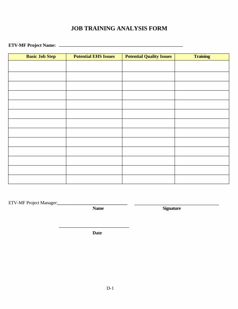
JOB TRAINING ANALYSIS FORM
ETV-MF Project Name:
Basic Job Step Potential EHS Issues Potential Quality Issues Training
ETV-MF Project Manager:______________________________Name Signature
Date
D-1

APPENDIX E
ETV-MF Project Training Attendance Form

ETV-MF Project Training Attendance Form ETV-MF Project:
Date Training Completed
Employe e Name Last First Training Topic
Test Score (If applic.)
ETV-MF Project Manager: Name Signature
Date
E-1

APPENDIX F
KCH ACTSEC Verification Test Field Data Collection Worksheet

KCH ACTSEC Verification Test - Field Data Collection Worksheet
Test # 1 – Tank Number Meter Value Temperature 911 Amps Volts �F 911 Duplicate Amps Volts �F 913 Amps Volts �F 913 Duplicate Amps Volts �F Hot Rinse Amps Volts �F Hot Rinse Duplicate Amps Volts �F
Test # 2 – Tank Number Meter Value Temperature 911 Amps Volts �F 911 Duplicate Amps Volts �F 913 Amps Volts �F 913 Duplicate Amps Volts �F Hot Rinse Amps Volts �F Hot Rinse Duplicate Amps Volts �F
Comments: _______________________________________________ Comments: ______________________________________________
Test # 3 – Pump Motor Meter Value Pump Amps Volts Pump Duplicate Amps Volts
Test # 4 – Tank Number Meter Value 911 Amps Volts 911 Duplicate Amps Volts
Comments: _______________________________________________ Comments: ______________________________________________
Test # 5 - Fan Meter Value Fan Amps Volts Fan Amps Volts
Test # 6 Air Velocity (ft/min) Traverse 1 Traverse 2 Average
Comments: _______________________________ Comments:____________________________________________________________________
Test #7 Static Pressure 7(a) wg 7(b) wg 7(c) wg 7(d) wg
Average wg
Tank Number Nameplate Value Other Equipment Nameplate Value 911 Element Amps Fan Amps 913 Element Amps Pump Motor Amps Hot Rinse Element Amps Tank opener /closer Amps
Comments:_____________________________ Comments:________________________________________________________________
ETV-MF Project Manager: _________________________________ Date: _________________
F-1