u.s. department of energy solar decathlon … · as built page - 1 u.s. d.o.e. solar decathlon 2011...
TRANSCRIPT

As Built Page - 1 U.S. D.O.E. Solar Decathlon 2011 Published 8/22/2013 Contents
PR
OJ
EC
T M
AN
UA
L
U.S. DEPARTMENT OF ENERGY SOLAR DECATHLON 2013
team
ken
tuckia
na@
gm
ail.c
om
C
on
str
uc
tio
n D
ocu
me
nts
F
eb
ruary
14,
20
13
As Built Page - 2 U.S. D.O.E. Solar Decathlon 2011 Published 8/22/2013 Contents
Contents
.......................................................................................................................................................................................................................................... 1
Summary of Changes ..................................................................................................................................................................................................... 5
Rules Compliance Checklist ........................................................................................................................................................................................ 18
Structural Calculations ................................................................................................................................................................................................ 21
Structural Calculations ................................................................................................................................................................................................ 21
Detailed Water Budget ................................................................................................................................................................................................. 65
Summary of Unlisted Electrical Components ............................................................................................................................................................ 66
Summary of Reconfigurable Features ........................................................................................................................................................................ 67
Interconnection Application Form .............................................................................................................................................................................. 68
Energy Analysis Results and Discussion .................................................................................................................................................................. 69
Quantity Takeoff of Competition Prototype House ................................................................................................................................................... 81
Construction Specifications ........................................................................................................................................................................................ 90
Division 01 – General Requirements ......................................................................................................................................................................... 93
SECTION 01 51 13 – TEMPORARY ELECTRICITY ............................................................................................................................................ 93
SECTION 01 54 19 – TEMPORARY CRANES .................................................................................................................................................... 95
Division 03 – Concrete ............................................................................................................................................................................................... 96
SECTION 03 40 00 – PRECAST CONCRETE ..................................................................................................................................................... 96
Division 05 – Metals ................................................................................................................................................................................................... 99
SECTION 05 12 00 – STRUCTURAL STEEL FRAMING ..................................................................................................................................... 99
Division 06 – Woods, Plastics, and Composites ...................................................................................................................................................... 101
SECTION 06 10 00 – ROUGH CARPENTRY ..................................................................................................................................................... 101
SECTION 06 12 00 – STRUCTURALLY INSULATED PANELS ........................................................................................................................ 104
SECTION 06 15 33 - WOOD DECKING ............................................................................................................................................................. 107
SECTION 06 16 53 – MOISTURE RESISTANT SHEATHING BOARD ............................................................................................................. 109
SECTION 06 17 53 – SHOP-FABRICATED WOOD TRUSSES ........................................................................................................................ 110
SECTION 06 40 23 – INTERIOR ARCHITECTURAL WOODWORK ................................................................................................................. 112
SECTION 06 41 00 – CUSTOM CASEWORK.................................................................................................................................................... 115
SECTION 06 41 93 – CABINET AND DRAWER HARDWARE .......................................................................................................................... 120
Division 07 – Thermal and Moisture Protection ....................................................................................................................................................... 122
SECTION 07 14 16 – COLD FLUID-APPLIED WATERPROOFING .................................................................................................................. 122
SECTION 07 21 16 – BLANKET INSULATION .................................................................................................................................................. 126
SECTION 07 21 19 – FOAMED-IN-PLACE INSULATION ................................................................................................................................. 128
SECTION 07 25 00 – WEATHER BARRIER ...................................................................................................................................................... 132
SECTION 07 26 13 – VAPOR RETARDER ........................................................................................................................................................ 136
SECTION 07 41 13 – METAL ROOF PANELS................................................................................................................................................... 139
SECTION 07 44 56 -- FIBER REINFORCED CEMENTITOUS PANEL ............................................................................................................. 144
As Built Page - 3 U.S. D.O.E. Solar Decathlon 2011 Published 8/22/2013 Contents
SECTION 07 45 23 – WOOD SIDING ................................................................................................................................................................ 148
SECTION 07 53 23 -- EPDM .............................................................................................................................................................................. 152
SECTION 07 71 23 – GUTTERS AND DOWNSPOUTS .................................................................................................................................... 156
SECTION 07 90 05 – JOINT SEALANTS ........................................................................................................................................................... 159
SECTION 07 91 16 – JOINT GASKETS ............................................................................................................................................................. 162
SECTION 07 92 13 – ELASTOMERIC JOINT SEALANTS ................................................................................................................................ 165
Division 08 – Openings ............................................................................................................................................................................................ 168
SECTION 08 10 00 – DOORS AND FRAMES ................................................................................................................................................... 168
SECTION 08 54 13 – FIBERGLASS WINDOWS ............................................................................................................................................... 173
Division 09 – Finishes .............................................................................................................................................................................................. 177
SECTION 09 29 00 – GYPSUM BOARD ............................................................................................................................................................ 177
SECTION 09 30 00 – TILING.............................................................................................................................................................................. 179
SECTION 09 31 00 – WALL FINISHES .............................................................................................................................................................. 182
Division 10 – Specialties .......................................................................................................................................................................................... 184
SECTION 10 28 16.13 – RESIDENTIAL BATH ACCESSORIES ....................................................................................................................... 184
Division 11 – Equipment .......................................................................................................................................................................................... 186
SECTION 11 30 00 – ELECTRONICS RESIDENTIAL ....................................................................................................................................... 186
SECTION 11 31 13 – RESIDENTIAL KITCHEN APPLIANCES ......................................................................................................................... 187
SECTION 11 31 23 – RESIDENTIAL LAUNDRY APPLIANCES ........................................................................................................................ 190
Division 12 – Furnishings ......................................................................................................................................................................................... 193
SECTION 12 20 00 – WINDOW TREATMENT .................................................................................................................................................. 193
SECTION 12 58 00 – RESIDENTIAL FURNITURE ............................................................................................................................................ 195
Division 21 – Fire Suppression ................................................................................................................................................................................ 197
SECTION 21 05 00 – COMMON WORK RESULTS FOR FIRE SUPPRESSION .............................................................................................. 197
SECTION 21 05 33 – HEAT TRACING FOR FIRE SUPPRESSION PIPING .................................................................................................... 200
SECTION 21 10 00 – WATER-BASED FIRE SUPPRESSION SYSTEMS ........................................................................................................ 202
Division 22 – Plumbing ............................................................................................................................................................................................ 205
SECTION 22 05 00 – COMMON WORK RESULTS FOR PLUMBING .............................................................................................................. 205
SECTION 22 07 00 – PLUMBING INSULATION ................................................................................................................................................ 207
SECTION 22 11 16 – DOMESTIC WATER PIPING ........................................................................................................................................... 209
SECTION 22 11 19 - DOMESTIC WATER PIPING SPECIALTIES .................................................................................................................... 211
SECTION 22 11 23 - DOMESTIC WATER PUMPS ........................................................................................................................................... 213
SECTION 22 12 19 – FACILITY GROUND-MOUNTED, POTABLE‐WATER STORAGE ................................................................................. 215
SECTION 22 13 16 – SANITARY WASTE AND VENT PIPING ......................................................................................................................... 217
SECTION 22 33 00 - ELECTRIC DOMESTIC WATER HEATERS .................................................................................................................... 219
SECTION 22 41 00 – RESIDENTIAL PLUMBING FIXTURES ........................................................................................................................... 221
SECTION 22 41 23 – RESIDENTIAL SHOWER RECEPTORS AND BASINS .................................................................................................. 225
Division 23 – Heating, Cooling, and Air Conditioning (HVAC) ................................................................................................................................. 228
SECTION 23 05 00 – COMMON WORK RESULTS FOR HVAC ....................................................................................................................... 228
SECTION 23 05 13 – COMMON MOTOR REQUIREMENTS FOR HVAC EQUIPMENT .................................................................................. 231
SECTION 23 05 23 –GENERAL DUTY VALVES FOR HVAC PIPING .............................................................................................................. 233
SECTION 23 05 93 – TESTING, ADJUSTING, AND BALANCING FOR HVAC ................................................................................................ 234
SECTION 23 07 00 – HVAC INSULATION......................................................................................................................................................... 236
SECTION 23 09 13 – INSTRUMENTATION AND CONTROL FOR HVAC ........................................................................................................ 239
SECTION 23 23 00 – REFRIGERANT PIPING .................................................................................................................................................. 241
SECTION 23 31 00 - HVAC DUCTS AND CASINGS ......................................................................................................................................... 243
SECTION 23 37 13 - DIFFUSERS, REGISTERS, AND GRILLES ..................................................................................................................... 246
As Built Page - 4 U.S. D.O.E. Solar Decathlon 2011 Published 8/22/2013 Contents
SECTION 23 62 00 - PACKAGED COMPRESSOR AND CONDENSER UNITS ............................................................................................... 248
SECTION 23 78 50 – AIR-TO-AIR ENERGY RECOVERY VENTILATORS ...................................................................................................... 250
Division 26 - Electrical.............................................................................................................................................................................................. 252
SECTION 26 05 00 - COMMON WORK RESULTS FOR ELECTRICAL ............................................................................................................ 252
SECTION 26 05 33 – RACEWAY & JUNCTION BOX FOR ELECTRICAL SYSTEMS ...................................................................................... 256
SECTION 26 09 23 – LIGHTING CONTROL DEVICES ..................................................................................................................................... 257
SECTION 26 22 00 – LOW-VOLTAGE TRANSFORMERS................................................................................................................................ 259
SECTION 26 24 16 – PANELBOARDS .............................................................................................................................................................. 261
SECTION 26 27 13 – ELECTRICITY METERING .............................................................................................................................................. 263
SECTION 26 27 26 – WIRING DEVICES ........................................................................................................................................................... 265
SECTION 26 27 13 – FUSES ............................................................................................................................................................................. 266
SECTION 26 28 16 – ENCLOSED SWITCHES AND CIRCUIT BREAKERS ..................................................................................................... 267
SECTION 26 28 16 – ENCLOSED CONTROLLERS ......................................................................................................................................... 269
SECTION 26 31 00 – PHOTOVOLTAIC COLLECTORS.................................................................................................................................... 271
SECTION 26 41 13 – LIGHTNING PROTECTION FOR STRUCTURES ........................................................................................................... 273
SECTION 26 43 13 – SURGE PROTECTION DEVICES ................................................................................................................................... 275
SECTION 26 51 00 – INTERIOR LIGHTING ...................................................................................................................................................... 276
SECTION 26 56 00 – EXTERIOR LIGHTING ..................................................................................................................................................... 279
Division 28 – Electronic Safety and Security ........................................................................................................................................................... 281
SECTION 28 31 11 – DIGITAL, ADDRESSABLE FIRE-ALARM SYSTEM ........................................................................................................ 281
SECTION 28 31 11 – SMOKE & CARBON MONOXIDE ALARM SYSTEM ....................................................................................................... 284
Division 32 – Exterior Improvements ....................................................................................................................................................................... 287
SECTION 32 71 00– CONSTRUCTED WETLANDS.......................................................................................................................................... 287
SECTION 32 93 00– PLANTS ............................................................................................................................................................................ 289
SECTION 32 94 33 – PLANTERS ...................................................................................................................................................................... 291
Division 48 – Electrical Power Generation ............................................................................................................................................................... 292
SECTION 48 19 16 – ELECTRICAL POWER GENERATION INVERTERS ...................................................................................................... 292
As Built Page - 5 U.S. D.O.E. Solar Decathlon 2011 Published 8/22/2013 Summary of Changes
Summary of Changes
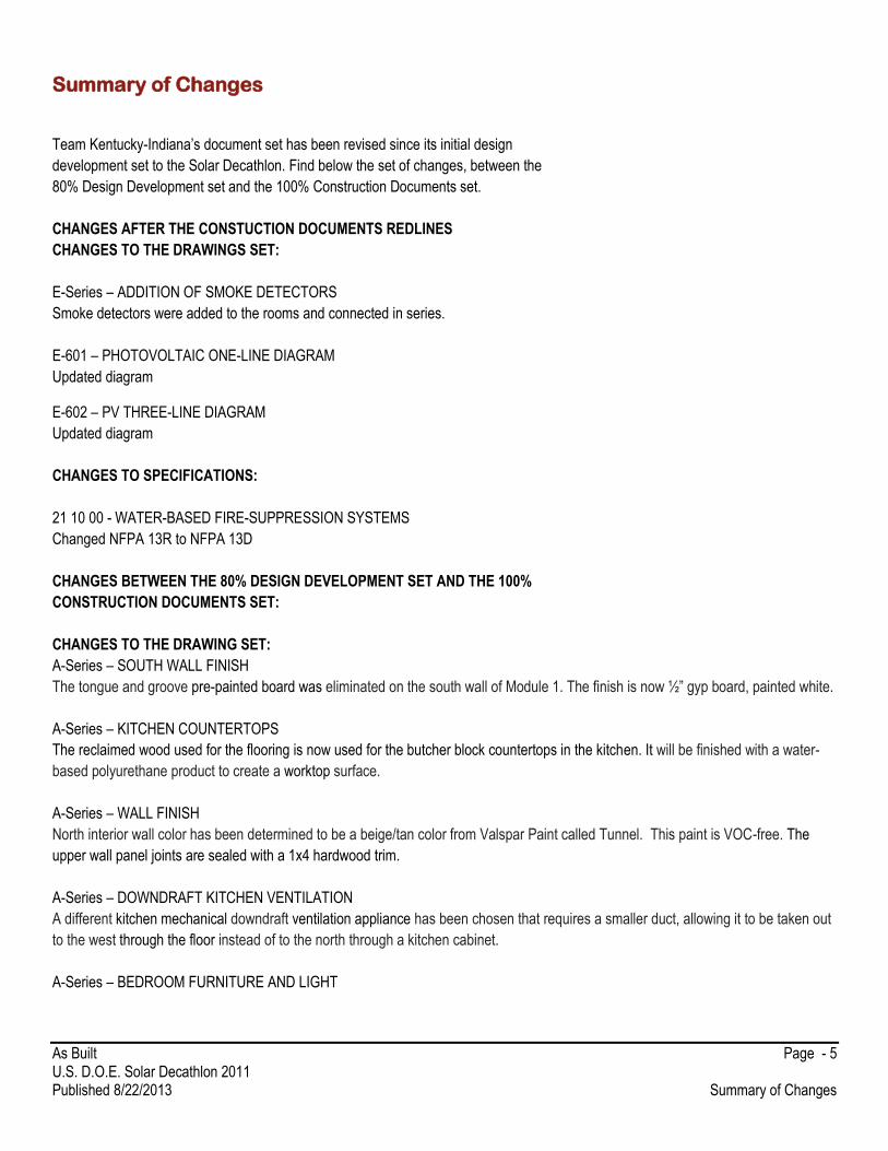
Team Kentucky-Indiana’s document set has been revised since its initial design
development set to the Solar Decathlon. Find below the set of changes, between the
80% Design Development set and the 100% Construction Documents set.
CHANGES AFTER THE CONSTUCTION DOCUMENTS REDLINES
CHANGES TO THE DRAWINGS SET:
E-Series – ADDITION OF SMOKE DETECTORS
Smoke detectors were added to the rooms and connected in series.
E-601 – PHOTOVOLTAIC ONE-LINE DIAGRAM
Updated diagram
E-602 – PV THREE-LINE DIAGRAM
Updated diagram
CHANGES TO SPECIFICATIONS:
21 10 00 - WATER-BASED FIRE-SUPPRESSION SYSTEMS
Changed NFPA 13R to NFPA 13D
CHANGES BETWEEN THE 80% DESIGN DEVELOPMENT SET AND THE 100%
CONSTRUCTION DOCUMENTS SET:
CHANGES TO THE DRAWING SET:
A-Series – SOUTH WALL FINISH
The tongue and groove pre-painted board was eliminated on the south wall of Module 1. The finish is now ½” gyp board, painted white.
A-Series – KITCHEN COUNTERTOPS
The reclaimed wood used for the flooring is now used for the butcher block countertops in the kitchen. It will be finished with a water-
based polyurethane product to create a worktop surface.
A-Series – WALL FINISH
North interior wall color has been determined to be a beige/tan color from Valspar Paint called Tunnel. This paint is VOC-free. The
upper wall panel joints are sealed with a 1x4 hardwood trim.
A-Series – DOWNDRAFT KITCHEN VENTILATION
A different kitchen mechanical downdraft ventilation appliance has been chosen that requires a smaller duct, allowing it to be taken out
to the west through the floor instead of to the north through a kitchen cabinet.
A-Series – BEDROOM FURNITURE AND LIGHT

As Built Page - 6 U.S. D.O.E. Solar Decathlon 2011 Published 8/22/2013 Summary of Changes
The bunk bed in Bedroom 1 has been moved to the west wall to allow more space in the bedroom. The fan/light was moved to avoid
conflicts with the bed.
A-Series – INTERIOR DOORS
The interior doors have been selected. The laundry/pantry door is wood with a dry erase surface. The bathroom door is an ENERGY
STAR exterior grade, steel door with a 90-minute fire rating. The bedroom and closet doors are hollow wood composite material and
pre-hung.
A-Series – BATHROOM WINDOW
The bathroom window was raised and changed to a clerestory window. The top of the window lines up with the other windows on the
south wall of Module 1.
A-Series – BATHROOM GLASS PARTITION
The glass partition between the toilet and shower area has been removed.
A-Series – FLOOR INSULATION
Foam insulation was added to the floor.
A-Series – STRUCTURAL INSULATED PANEL
The upper SIP panels of Module 1 were reduced in number vertically from 3 to 1
A-Series – FIBER CEMENTITIOUS BOARD
Rainscreen was adjusted to match all reveals with openings..
A-Series – APPLIANCE RELOCATION
The stacked washer and dryer were moved to the south wall of the laundry room where there is no door jamb, to make space for a
shelf on the north wall.
A-Series – CABINET PULLS
Cabinet pulls have been selected. They are modern handles, with a satin nickel finish.
A-Series – WINDOW TREATMENT
All windows that are not clerestory windows have been fitted with light-filtering energy-efficient cellular shades.
A-Series – LOOSE FURNITURE
The loose furniture for interior and exterior has been chosen. This includes a sofa bed, ottomans, living chairs, stackable dining chairs,
a bunk bed, and master bedroom bed storage.
A-Series and L-Series – LIGHTING
New lighting fixtures have been picked out. Changes include one floor lamp, 20 track fixtures between two tracks over the island and
the kitchen circulation, a 3-fixture light in the bathroom, and circular surface mounted lights in the mechanical room and closets.
Exterior Lighting fixtures were relocated and adjusted.
A-402 – BATHROOM ACCESSORIES
The bathroom accessories have all been chosen. This includes the sink, faucet, towel bars, showerhead and arm, and toilet paper
dispenser.
As Built Page - 7 U.S. D.O.E. Solar Decathlon 2011 Published 8/22/2013 Summary of Changes
A-402 – BATHROOM TILE
Bathroom tile has been chosen from Crossville Tile.
A-Series and G-Series – WINDOW AND DOOR OPENINGS
The French doors frame type has been updated to allow for full swing outward. The details for both windows and doors were changed
to match manufacturer’s specifications.
F-SERIES SHEETS
Relocated system due to rethinking of design - moved sprinklers to the North (highest point of the interior space) so water could come
out of sprinkler heads and reach any possible fire.
Considering the use of a separate pump for FIRE SUPPRESSION, not in model at this time.
G-Series and L-Series – TRELLISES AND CARPORT
The roof over the SE patio has been replaced by a trellis. The trellis dimensions on the back have been changed.
The carport has been eliminated.
G-Series and L-Series – DECK AND RAMPS
The ramp on the north side has been eliminated. The grass area on the North side has been eliminated. A handrail has been added, so
that there are handrails on both sides of the ramps. Railing on the front porch has been eliminated. The slope of the exit ramp has been
changed to 3/4"/1’0”. The 3 ft or 4 ft-wide planters around the back deck have been lowered and extended the full width of the deck.
Custom built benches have been added, serving as storage.
L-Series – PLANTS AND WATER TREATMENT SYSTEM
The planting plan has been revised consistently with the exterior design changes. The water treatment system and plumbing design
has been developed.
M-SERIES Moved return ducting towards the middle of module 1 and rerouted the return run to the second bedroom. Changed the duct sizes for both the supplies and return runs. Changed the air handler unit. Added an ERV. Rerouted exhaust and intake for system. Changed orientation of the air handler in mechanical room. Changed multiple register sizes. Took out veins in the return elbows. Changed the downdraft fan ducting size and routing. M-101-HVAC EQUIPMENT AND DISTRIBUTION PLAN Made the First Floor Equipment and Distribution Plan to only show the equipment above the floor but bellow the loft and resized the view. Added the Loft Equipment and Distribution Plan to better show the ERV and ducting in loft area. Added sheet keynotes, section views, and a callout. M-102-HVAC EQUIPMENT AND DISTRIBUTION PLAN Created this sheet and Underslab Equipment and Distribution Plan view to show only the mechanical equipment below the floor. Added sheet keynotes. M-401-MECHANICAL ROOM HVAC PLAN AND ELEVATIONS Deleted the HVAC East Elevation view, was basically a duplicated view of the HVAC West Elevation. Used the callout from M-101 for the HVAC Mechanical Room Plan. Added mechanical room equipment clearances and sheet keynotes. M-402-HVAC DUCT ROUTING Created this view and sheet to show the duct paths through the floor joists.

As Built Page - 8 U.S. D.O.E. Solar Decathlon 2011 Published 8/22/2013 Summary of Changes
M-601-SCHEDULES Created this sheet to show all ducting, fittings, equipment, etc. schedules. M-901-COMPLETE HVAC ISOMETRIC Changed what was shown in this view to only show the HVAC ducting, fittings, equipment, joists, and chassis. Added the joists and
chassis to this view to better show the duct routing. Annotated the return and supply ducting by assigning a specific color and category
tags. Used sheet keynotes.
M-902-COMPLETE HVAC ISOMETRIC Deleted this sheet.
M-903-COMPLETE HVAC ISOMETRIC Deleted this sheet.
M-904-COMPLETE HVAC ISOMETRIC Deleted this sheet.
P-SERIES SHEETS
Corrected keynotes/tags, to be smart tags which more accurately reflect NCS standards and correspond to schedules.
P-101 – PLUMBING SITE PLAN
Added GENERAL SHEET NOTES and SHEET KEYNOTES for ease of construction
Corrected size of rainwater collection tank and renamed it (formally ‘irrigation tank’), multiple views
P-102 – DOMESTIC SUPPLY
Added Detail 2 of the PEX manifold located in the mechanical room
Added GENERAL SHEET NOTES and REFERENCE KEYNOTES for ease of construction and Referencing the Project Manual
P-103 - WASTE REMOVAL, GREY WATER, & VENTING
Added GENERAL SHEET NOTES and SHEET KEYNOTES for ease of construction
P-601 – SCHEDULES
Updated plumbing schedules to include the plumbing fixtures, manufacture, model, tag/keynote information if available. Not an
exhaustive schedule for every fitting, elbow, valve, etc. that may be required to meet IRC 2012.
P-901 – COMPLETE PLUMBING ISOMETRIC
Connected waste/grey water lines to respective tanks
P-902 – SUPPLY ISOMETRIC
Connected PEX supply lines to the manifold and ran them to respective fixtures. Note did not connect to fixtures because final
connection will be done with flexible steel or similar hose. Color coded hot and cold supply lines with red and blue respectively
P-903 - WASTE REMOVAL, GREY WATER, & VENTING ISOMETRIC
Include changes to sheet P-901 as changes made to it are applicable to P-903
Color coded venting pipe with green to indicate that water would not be flowing through it. Waste and Grey Water drains remained the
same
As Built Page - 9 U.S. D.O.E. Solar Decathlon 2011 Published 8/22/2013 Summary of Changes
CHANGES TO SPECIFICATIONS:
05 52 13 – PIPE AND TUBERAILING
Updates to locations and materials
06 10 00 – ROUGH CARPENTRY
Updates to specific locations and materials
06 12 00 – STRUCTURAL INSULATED PANELS
Updated related sections
06 15 33 – WOOD DECKING
Updates to decking product information
06 20 13 – EXTERIOR FINISHED CARPENTRY
Removed Specification
06 40 23 - INTERIOR ARCHITECTURAL WOODWORK
Specifications moved from 09 64 29 WOOD FLOORING AND TRIM
06 41 00 – ARCHITTECTURAL WOOD CASEWORK
Updates to specific locations and materiality
06 41 93 – CABINETAND DRAWER HARDWARE
Insertion of new cabinet pull product information
07 14 16 – COLD FLUID-APPLIED WATERPROOFING
Spec. Added. Insertion of waterproofing product information
07 21 16 – BLANKET INSULATION
Spec updated to include product and manufacturer
07 21 19 – FOAMED IN PLACE INSULATION
Spec. Added. Insertion of insulation product information
07 25 00 – WEATHER BARRIER
Removed weather barrier from building envelope
07 44 56 – FIBER REINFORCED CEMENTITOUS PANEL
Updated Related Sections and Accessories
07 46 23 – WOOD SIDING
Update to insulation product information
07 91 16 - JOINT GASKETS
Updated product information and manufacturer

As Built Page - 10 U.S. D.O.E. Solar Decathlon 2011 Published 8/22/2013 Summary of Changes
08 10 00 - DOORS AND FRAMES
Updates to new interior door selections
08 54 13 – FIBERGLASS WINDOWS
Update to safety glass product information
09 29 00 – GYPSUM BOARD
Updated to include manufacturer and product information
09 30 00 – TILING
Updates to specific manufacturer and tiles
09 31 00 – WALL FINISHES
Spec Added. Insertion of paint information
10 22 00 – GLASS PARTITION
Removed glass partition in bathroom
10 28 16.13 – BATHROOM ACCESSORIES
Insertion of bathroom accessory product information, including faucet, sink, shower head and arm, toilet paper holder
11 30 00 – RESIDENTIAL ELECTRONICS
Spec Added. Insertion of TV and Blu-ray player product information
11 31 13 – RESIDENTIAL KITCHEN APPLIANCES
Updates to residential kitchen appliances
12 20 00 - WINDOW TREATMENT
Insertion of window treatment product information
12 36 19 – WOOD COUNTERTOPS
Removed section, information moved to 09 64 29 INTERIOR ARCHITECTURAL WOODWORK
12 58 00 - RESIDENTIAL FURNITURE
Insertion of loose furniture product information
22 12 19 – FACILITY GROUND-MOUNTED, POTABLE WATER STORAGE
Updates to tank dimensions and capacities.
22 41 00 – RESIDENTIAL PLUMBING FIXTURES
Updates to faucet, sink, and showerhead and arm fixtures
22 41 23 - RESIDENTIAL SHOWER RECEPTORS AND BASINS
Insertion of shower tray product information
As Built Page - 11 U.S. D.O.E. Solar Decathlon 2011 Published 8/22/2013 Summary of Changes
26 24 16 - PANELBOARD
Updated specs
26 31 00 – PHOTOVOLTAIC COLLECTORS
Panel specs updated.
26 50 00 - INTERIOR LIGHTING
Updates to light fixture selections
26 50 00 - EXTERIOR LIGHTING
Updates to light fixture selections
32 93 00 - PLANTS
Updates to planting schedule
32 94 33 – PLANTERS
Spec. Added.
32 97 10 – CONSTRUCTED WETLANDS
Updates to development of water filtration system
NOV. 20th 2012 – DESIGN DELIVERABLE REVIEW
DRAWINGS:
A-102 – FIRST FLOOR PLAN Added ½” layer of gypsum board on interior to meet IRC R316. Added wall type schedule to sheet. A-103 – LOFT FLOOR PLAN Added ½” layer of gypsum board on interior to meet IRC R316. A-104 – ROOF PLAN Remove carport assembly from scope of work
A-111 – FIRST FLOOR LOFT AND REFLECTED CEILING PLANS
Modified lighting plan and fixtures
A-201 – SITE ELEVATIONS Modified planter box sizes. Remove carport assembly from scope of work A-202 – SITE ELEVATIONS Modified planter box sizes. Remove carport assembly from scope of work A-211 – EXTERIOR ELEVATIONS Modify upper wall SIPs to allow for two man lifting weights. A-212 – EXTERIOR ELEVATIONS

As Built Page - 12 U.S. D.O.E. Solar Decathlon 2011 Published 8/22/2013 Summary of Changes
Changes according to changes in scope of work
A-214 – MODULE 1 INTERIOR ELEVATIONS
Plywood panels and tongue and groove wood planks changed to gypsum board to comply with fire rating regulations.
A-215 – MODULE 2 INTERIOR ELEVATIONS
Tongue and groove wood planks changed to finished plywood.
A-311 – BUILDING SECTIONS Changed exterior wall construction to SIPs. Added ½” layer of gypsum board on interior to meet IRC R316. A-312 – BUILDING SECTIONS Changed exterior wall construction to SIPs. Added ½” layer of gypsum board on interior to meet IRC R316. A-321 – WALL SECTIONS Changed exterior wall construction to SIPs. Added ½” layer of gypsum board on interior to meet IRC R316. A-322 – WALL SECTIONS Changed exterior wall construction to SIPs. Added ½” layer of gypsum board on interior to meet IRC R316. A-323 – WALL SECTIONS Changed exterior wall construction to SIPs. Added ½” layer of gypsum board on interior to meet IRC R316. A-403 – ENLARGED BATHROOM PLAN
Tongue and groove wood planks changed to gypsum board to comply with fire rating regulations. Cement board changed to ceramic
tile.
A-501 – PLAN DETAILS Updated details to include SIP wall construction and added ½” layer of gypsum board on interior to meet IRC R316.
A-511 – SECTION DETAILS Updated details to include SIP wall construction and added ½” layer of gypsum board on interior to meet IRC R316. A-512 – SECTION DETAILS Updated details to include SIP wall construction and added ½” layer of gypsum board on interior to meet IRC R316. A-531 – WINDOW DETAILS Updated details to include SIP wall construction and added ½” layer of gypsum board on interior to meet IRC R316. A-541 – DOOR DETAILS Updated details to include SIP wall construction and added ½” layer of gypsum board on interior to meet IRC R316. A-561 – ROOF DETAILS Updated details to include SIP wall construction and added ½” layer of gypsum board on interior to meet IRC R316.
E-001 – ELECTRICAL SYMBOLS AND NOTES
Added Electrical legend with symbols and notes.
E-101 – ELECTRICAL DISTRIBUTION PLAN

As Built Page - 13 U.S. D.O.E. Solar Decathlon 2011 Published 8/22/2013 Summary of Changes
Placed General Sheet Notes, Reference Keynotes, and Sheets notes. Added Circuits and wiring. Adjusted equipment according to
floor plans.
E-102 – PV WIRING PLAN
Placed General Sheet Notes, Reference Keynotes, and Sheets notes. Connected Arrays to panels, and inverters to main service
panels.
E-103 – LIGHTING PLAN
Placed General Sheet Notes, Reference Keynotes, and Sheets notes. Added connections to ceiling junction boxes and laid out
switches.
E-401 – HARDWIRED EQUIPMENT PLAN
Placed General Sheet Notes, Reference Keynotes, and Sheets notes. Provided connections to hardwired equipment with circuit
destinations.
E-601 – PHOTOVOLTAIC ONE-LINE DIAGRAM
Placed General Sheet Notes, Reference Keynotes, and Sheets notes. Provided size and type for each conductor and conduit.
E-602 – PV THREE-LINE DIAGRAM
Placed General Sheet Notes, Reference Keynotes, and Sheets notes. Provided size and type for each conductor and conduit. Sized
disconnect switch and overcurrent protection device. Provided GEC and EGC for necessary equipment.
E-603 – SCHEDULES
Placed General Sheet Notes, Reference Keynotes, and Sheets notes. Added Panelboard and service feeder schedules.
E-604 – PV THREE-LINE CALCULATIONS
Placed General Sheet Notes, Reference Keynotes, and Sheets notes. Showed how each equipment or wire was sized.
F-102-FIRE SUPPRESSION Rerouted one wet fire suppression line, add one sprinkler to the mechanical, and connected piping to the water pump. Added tags to certain sections of the piping. F-601-FIRE PROTECTION ISOMETRIC Created the view and added this sheet. F-602-FIRE PROTECTION ISOMETRIC Created the view and added this sheet. G-101 – FINISHED SQ. FT. COMPLIANCE PLAN
Changes to calculations of finished/unfinished areas to comply with ANSI Z765
G-103 – ADA TOUR ROUTE COMPLIANCE PLAN
Changes to improve tour path
L-102 – LANDSCAPE IRRIGATION AND GREYWATER PLAN Sheet Keynote legend added to indicate used sheet keynotes L-103 – LANDSCAPE LIGHTING PLAN Updated to reflect current lighting design.
As Built Page - 14 U.S. D.O.E. Solar Decathlon 2011 Published 8/22/2013 Summary of Changes
L-104 – PLANTER BOX PLAN Updated to reflect current planter box configuration and design L-105 – DECK PLAN Updated to reflect current deck configuration and design L-501 – SITE DETAILS Updated to reflect current details L-502 – SITE DETAILS Updated to reflect current details M-101-HVAC EQUIPMENT AND DISTRIBUTION PLAN Created a floor plan view and used it instead of the 3D overhead view from last submission. Tagged the same as last submission’s sheet but added more tags for the equipment. Added directional arrows on the registers to show the airflow. M-903-HVAC ISOMETRIC Created this view and sheet to show only the supply ducting. M-904-HVAC ISOMETRIC Created this view and sheet to show only the return ducting. O-901 – 3D REPRESENTATION ASSEMBLY DIGRAMS Updated sequence based on DOE comments and feedback about neighbor and access ways. . P-101 – PLUMBING SITE PLAN Added keynotes for tanks, pumps, pipes, water heater, and pex manifold. P-601 – SCHEDULES Created a schedule for plumbing,* not completed yet. P-901 – COMPLETE PLUMBING ISOMETRIC Added proper vent stacks, drainage to waste water tank and grey water tank, pump for main supply, pump for grey water recycling, piping connecting grey water tank pump to biofilter. P-902 – SUPPLY ISOMETRIC Added fresh water supply pump and ran supply pipe to the pex manifold. P-903 – RETURN ISOMETRIC Added vent stacks for kitchen sink and bathroom combined with clothes washer, grey water pump S-001 – STRUCTURAL NOTES AND SYMBOLS Sheet Created and updated S-101 – FOUNDATION PLAN Updated and completed. S-102 – FLOOR FRAMING PLAN Updated and completed S-103 – ROOF FRAMING PLAN Updated and Completed

As Built Page - 15 U.S. D.O.E. Solar Decathlon 2011 Published 8/22/2013 Summary of Changes
S-104 – DECK FRAMING PLAN Created and updated S-105 LOFT FRAMING PLAN Added load bearing wall S-201 – FRAMING ELEVATIONS Created for truss element for roof S-301 – FRAMING SECTIONS Floor Joist elevation and tie down elevations created S-501 – PLAN DETAILS Footing and ramp details created S-602 – COLUMN AND BEAM SCHEDULES Footing schedules added SPECIFICATIONS: 01 51 13 – TEMPORARY ELECTRICITY Specified Generator and spill containment. 06 12 00 – STRUCTURAL INSULATED PANELS Section updated to reflect scope of work 07 21 13 – BOARD INSULATION Section removed from scope of work 07 21 19 – FOAMED-IN-PLACE INSULATION Section removed from scope of work 07 41 13 – METAL ROOF PANELS Section updated to reflect updated product 07 44 56 – FIBER REINFORCED CEMENTITOUS PANELS Section updated to reflect updated product
09 29 00 – GYPSUM BOARD
Section added to reflect changes in scope of work 09 74 13 – WOOD WALL COVERING
Section deleted, products changed.
11 31 13 – RESIDENTIAL KITCHEN APPLIANCES
Section products changed.
21 10 00 – WATER-BASED FIRE SUPPRESSION SYSTEMS Specified sprinklers and updated fire suppression systems.
As Built Page - 16 U.S. D.O.E. Solar Decathlon 2011 Published 8/22/2013 Summary of Changes
22 05 00 – COMMON WORK RESULTS FOR PLUMBING Removed unnecessary specifications and added more specific features. 22 05 13 – COMMON MOTOR REQUIREMENTS FOR PLUMBING EQUIPMENT Division deleted to reflect changes in scope of work. 22 05 23 – GENERAL DUTY VALVES FOR PLUMBING PIPING Division deleted to reflect changes in scope of work. 22 07 00 – PLUMBING INSULATION Specified insulation choice and removed unneeded information. 22 11 16 – DOMESTIC WATER PIPING Division deleted due to duplicate specs. 22 11 19 – DOMESTIC WATER PIPING SPECIALTIES Added expansion tank and removed unnecessary specs. 22 11 23 – DOMESTIC WATER PUMPS Specified the domestic pump for the water supply. 22 12 00 – FACILITY POTABLE WATER STORAGE Division added to reflect changes in scope of work. 22 13 13 – FACILITY SANITARY SEWERS Division deleted due to duplicate specs. 22 12 16 – SANITARY WASTE AND VENT PIPING Specified pipes and fittings for the water system. 22 13 19 – SANITARY WASTE PIPING SPECIALTIES Division deleted due to duplicate specs. 22 14 13 – FACILITY STORM DRAINAGE PIPING Division deleted due to duplicate specs. 22 33 00 – ELECTRONIC DOMESTIC WATER HEATERS Specified appliance dimensions and electrical requirements. 22 33 00 – ELECTRONIC DOMESTIC WATER HEATERS Division deleted due to duplicate specs.
22 41 00 – RESIDENTIAL PLUMBING FIXTURES
Section products changed
23 07 00 - HVAC INSULATION Removed unnecessary information about polyolefin insulation 23 23 00 - REFRIGERANT PIPING Added specific pressure and temperature values for valves and specialties

As Built Page - 17 U.S. D.O.E. Solar Decathlon 2011 Published 8/22/2013 Summary of Changes
23 37 13 - DIFFUSERS, REGISTERS, AND GRILLES Corrected grammatical mistakes and deleted unneeded information for ceiling ducts and accessories
23 62 00 - PACKAGED COMPRESSOR AND CONDENSER UNITS Corrected grammatical mistakes 260533 – RACEWAY & BOXES FOR ELECTRICAL SYSTEMS
Specified conductor & box types. Clarification of wiring.
262416 – PANELBOARD
Updated type of circuit breaker panel based on modifications to the house.
26 51 00 – INTERIOR LIGHTING Section products changed

As Built Page - 18 U.S. D.O.E. Solar Decathlon 2011 Published 8/22/2013 Rules Compliance Checklist
Rules Compliance Checklist
RULE RULE DESCRIPTION LOCATION DESCRIPTION LOCATION
Rule 4-2 Construction Equipment Drawing(s) showing the assembly and disassembly sequences and the movement of heavy machinery on the competition site
O-901
Rule 4-2 Construction Equipment Specifications for heavy machinery
Rule 4-3 Ground Penetration Drawing(s) showing the locations and depths of all ground penetrations on the competition site
S-Series
Rule 4-4 Impact within the Solar Envelope
Drawing(s) showing the location, contact area, and bearing pressure of every component resting directly within the solar envelope
S-102, C-101,
Rule 4-5 Generators Specifications for generators (including sound rating) 01 51 13
Rule 4-6 Spill Containment Drawing(s) showing the locations of all equipment, containers, and pipes that will contain liquids at any point during the event
P-101, P-102, P-103
Rule 4-6 Spill Containment Specifications for all equipment, containers, and pipes that will contain fluids at any point during the event
01 51 13, 22 XX XX,
Rule 4-7 Lot Conditions Calculations showing that the structural design remains compliant even if 18 in. (45.7 cm) of vertical elevation change exists
S-101
Rule 4-7 Lot Conditions Drawing(s) showing shimming methods and materials to be used if 18 in. (45.7 cm) of vertical elevation change exists on the lot
S-101
Rule 5-2 Solar Envelope Dimensions Drawing(s) showing the location of all house and site components relative to the solar envelope
G-201, G-202
Rule 5-2 Solar Envelope Dimensions List of solar envelope exemption requests accompanied by justifications and drawing references
N/A
Rule 6-1 Structural Design Approval List of, or marking on, all drawing and project manual sheets that will be stamped by the qualified, licensed design professional in the stamped structural submission; the stamped submission shall consist entirely of sheets that also appear in the drawings and project manual
S-Series
Rule 6-2 Finished Square Footage Drawing(s) showing all information needed by the rules officials to measure the finished square footage electronically
G-101
Rule 6-2 Finished Square Footage Drawing(s) showing all movable components that may increase the finished square footage if operated during contest week
N/A

As Built Page - 19 U.S. D.O.E. Solar Decathlon 2011 Published 8/22/2013 Rules Compliance Checklist
Rule 6-3 Entrance and Exit Routes Drawing(s) showing the accessible public tour route G-103
Rule 7-1 Placement Drawing(s) showing the location of all vegetation and, if applicable, the movement of vegetation designed as part of an integrated mobile system
L-101
Rule 7-2 Watering Restrictions Drawing(s) showing the layout and operation of greywater irrigation systems
L-102
Rule 8-1 PV Technology Limitations Specifications for photovoltaic components 26 31 00
Rule 8-3 Batteries Drawing(s) showing the location(s) and quantity of all primary and secondary batteries and stand-alone, PV-powered devices
Rule 8-3 Batteries Specifications for all primary and secondary batteries and stand-alone, PV-powered devices
Rule 8-4 Desiccant Systems Drawing(s) describing the operation of the desiccant system N/A
Rule 8-4 Desiccant Systems Specifications for desiccant system components N/A
Rule 8-5 Village Grid Completed interconnection application form PM page
Rule 8-5 Village Grid Drawing(s) showing the locations of the photovoltaics, inverter(s), terminal box, meter housing, service equipment, and grounding means
E-102, E-601, E-602
Rule 8-5 Village Grid Specifications for the photovoltaics, inverter(s), terminal box, meter housing, service equipment, and grounding means
E-604, 26 24 19, 26 31 00
Rule 8-5 Village Grid One-line electrical diagram E-601
Rule 8-5 Village Grid Calculation of service/feeder net computed load per NEC 220
E-604
Rule 8-5 Village Grid Site plan showing the house, decks, ramps, tour paths, and terminal box
E-101
Rule 8-5 Village Grid Elevation(s) showing the meter housing, main utility disconnect, and other service equipment
E-101
Rule 9-1 Container Locations Drawing(s) showing the location of all liquid containers relative to the finished square footage
H-101
Rule 9-1 Container Locations Drawing(s) demonstrating that the primary supply water tank(s) is fully shaded from direct solar radiation between 9 a.m. and 5 p.m. PDT or between 8 a.m. and 4 p.m. solar time on October 1
P-102, P-901
Rule 9-2 Team-Provided Liquids Quantity, specifications, and delivery date(s) of all team-provided liquids for irrigation, thermal mass, hydronic system pressure testing, and thermodynamic system operation
P-101
Rule 9-3 Greywater Reuse Drawing(s) showing the layout and operation of greywater reuse systems
L-102
Rule 9-4 Rainwater Collection Drawing(s) showing the layout and operation of rainwater collection systems
P-101
As Built Page - 20 U.S. D.O.E. Solar Decathlon 2011 Published 8/22/2013 Rules Compliance Checklist
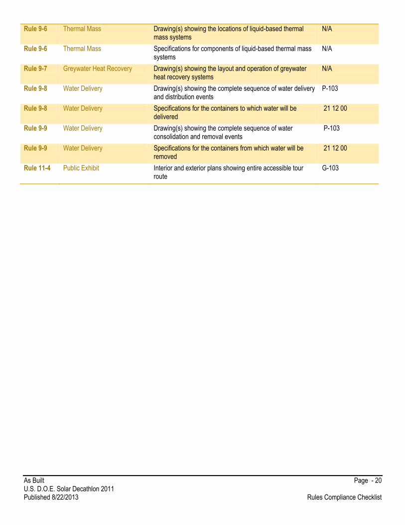
Rule 9-6 Thermal Mass Drawing(s) showing the locations of liquid-based thermal mass systems
N/A
Rule 9-6 Thermal Mass Specifications for components of liquid-based thermal mass systems
N/A
Rule 9-7 Greywater Heat Recovery Drawing(s) showing the layout and operation of greywater heat recovery systems
N/A
Rule 9-8 Water Delivery Drawing(s) showing the complete sequence of water delivery and distribution events
P-103
Rule 9-8 Water Delivery Specifications for the containers to which water will be delivered
21 12 00
Rule 9-9 Water Delivery Drawing(s) showing the complete sequence of water consolidation and removal events
P-103
Rule 9-9 Water Delivery Specifications for the containers from which water will be removed
21 12 00
Rule 11-4 Public Exhibit Interior and exterior plans showing entire accessible tour route
G-103

As Built Page - 21 U.S. D.O.E. Solar Decathlon 2011 Published 8/22/2013 Structural Calculations
Structural Calculations
Structural Calculations
THE FOLLOWING STRUCTURAL NOTES COMPRISE THE STRUCTURAL DESIGN FOR THE PHOENIX HOUSE
FOR THE WORST CONDITIONS DESCRIBED IN THE 2013 SOLAR DECATHLON BUILDING CODE REQUIREMENTS OR
THE IRC 2012 REQUIREMENTS FOR LOUISVILLE KY.
I HAVE PLACED MY KENTUCKY PROFESSIONAL ENGINEERING STAMP BELOW INDICATING I HAVE EITHER
GENERATED OR REVIEWED THE FOLLOWING SHEETS.
The Structural design of the Phoenix House was conducted in accordance to the Provisions in the IRC 2012 and assumed the following maximum design load conditions: a) Wind: 85 mph (38.0 m/s) (3-second gust), exposure category C. ASCE 7 – 10 now uses Minimum Strength level loads and a 110 MPH is the value listed for Louisville, KY. This strength level wind speed gives equivalent loading to the 85 MPH in the non-strength levels. Thus the 110 MPH value was used for the design. The structure is be sited in Louisville, KY after the competition. b) Seismic: IRC Seismic Design Category (SDC) D2 See IRC Section R301.2.2. The Maximum SDS Value for the D2 Category is 1.17 g as per the IRC. This is greater than the permanent siting Seismic Design Category so will be used for design. c) Railings: 200 lb (890 N) concentrated load applied in any direction at any point at the top of the rail d) Interior floor, decks, ramps: 50 psf (2.39 kPa) live load e) Exterior floor, decks, ramps used for tour staging and egress purposes: 100psf (4.79 kPa) live load f) Roof: 20 psf (0.958 kPa) live load
As Built Page - 22 U.S. D.O.E. Solar Decathlon 2011 Published 8/22/2013 Structural Calculations
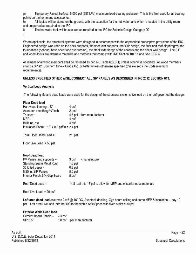
g) Temporary Paved Surface: 6,000 psf (287 kPa) maximum load-bearing pressure. This is the limit used for all bearing points on the home and accessories. h) All liquids will be stored on the ground, with the exception for the hot water tank which is located in the utility room and supported as required in the IRC. i) The hot water tank will be secured as required in the IRC for Seismic Design Category D2. . Where applicable, the structural systems were designed in accordance with the appropriate prescriptive provisions of the IRC. Engineered design was used on the deck supports, the floor joist supports, roof SIP design, the floor and roof diaphragms, the foundations (bearing, base shear and overturning), the steel wide flange of the chassis and the shear wall design. The SIP and wood Joists are alternate materials and methods that comply with IRC Section 104.11 and Sec. CC2.6. All dimensional wood members shall be fastened as per IRC Table 602.3(1) unless otherwise specified. All wood members shall be SP #2 (Southern Pine – Grade #2) or better unless otherwise specified (this exceeds the Code minimum requirements). UNLESS SPECIFIED OTHER WISE, CONNECT ALL SIP PANELS AS DESCRIBED IN IRC 2012 SECTION 613. Vertical Load Analysis The following life and dead loads were used for the design of the structural systems live load on the roof governed the design: Floor Dead load Hardwood flooring – ¾” – 4 psf Avantech sheathing ¾” inch 2. psf Trusses - 4.6 psf - from manufacturer MEP - 4 psf Built ins, etc 4 psf Insulation Foam – 12” x 0.2 psf/in = 2.4 psf Total Floor Dead Load = 21 psf Floor Live Load = 50 psf Roof Dead load PV Panels and supports – 3 psf - manufacturer Standing Seam Metal Roof 1.5 psf 30 lb felt paper - 0.3 psf 8.25 in. SIP Panels 5.0 psf Interior Finish & ½ Gyp Board 5 psf Roof Dead Load = 14.8 call this 16 psf to allow for MEP and miscellaneous materials Roof Live Load = 20 psf Loft area dead load assumes 2 x 6 @ 16” OC, Avanteck decking, Gyp board ceiling and some MEP & insulation. – say 10 psf – Loft area Live load per the IRC for habitable Attic Space with fixed stairs = 30 psf Exterior Walls Dead load Cement Board Panels – 2.3 psf SIP 6.5” 5.0 psf per manufacturer
As Built Page - 23 U.S. D.O.E. Solar Decathlon 2011 Published 8/22/2013 Structural Calculations
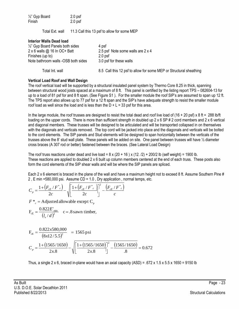
½” Gyp Board 2.0 psf Finish 2.0 psf Total Ext. wall 11.3 Call this 13 psf to allow for some MEP Interior Walls Dead load ½” Gyp Board Panels both sides 4 psf 2 x 6 walls @ 16 In OC+ Batt 2.5 psf Note some walls are 2 x 4 Finishes (up to) 2.0 psf Note bathroom walls -OSB both sides 3.0 psf for these walls
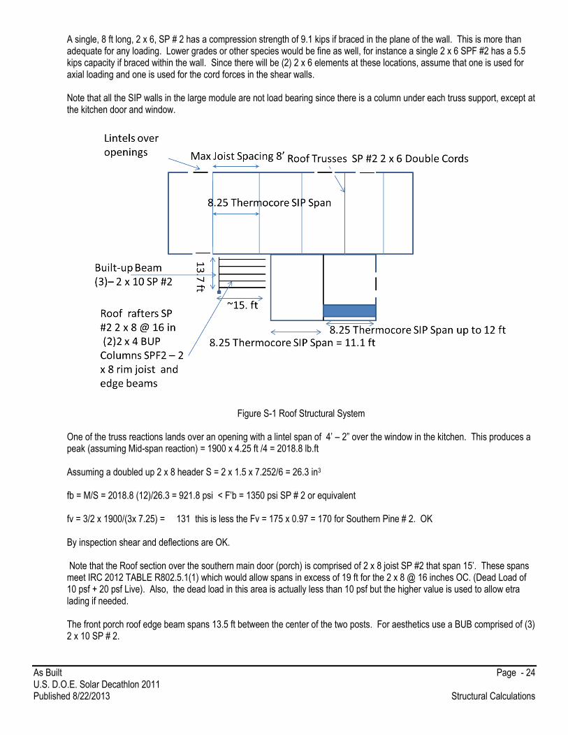
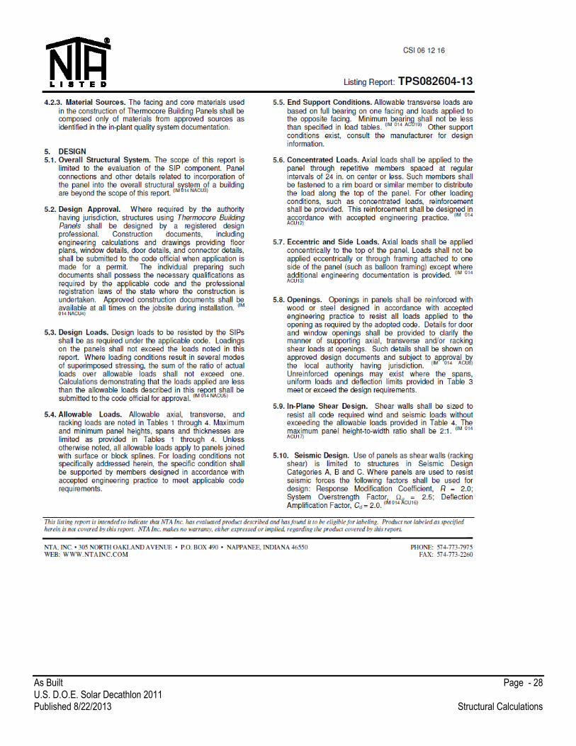
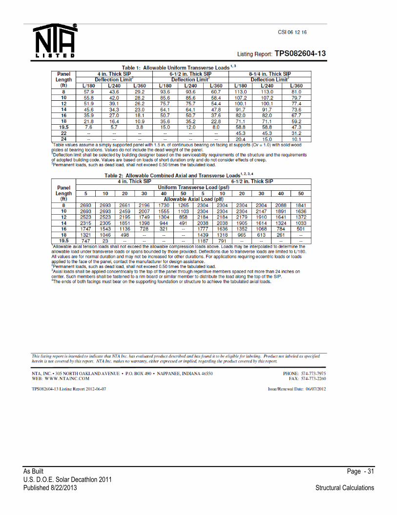
Total Int. wall 8.5 Call this 12 psf to allow for some MEP or Structural sheathing Vertical Load Roof and Wall Design The roof vertical load will be supported by a structural insulated panel system by Thermo Core 8.25 in thick, spanning between structural wood joists spaced at a maximum of 8 ft. This panel is certified by the listing report TPS – 082604-13 for up to a load of 81 psf for and 8 ft span. (See Figure S1 ). For the smaller module the roof SIP’s are assumed to span up 12 ft. The TPS report also allows up to 77 psf for a 12 ft span and the SIP’s have adequate strength to resist the smaller module roof load as well since the load and is less than the D + L = 33 psf for this area.
In the large module, the roof trusses are designed to resist the total dead and roof live load of (16 + 20 psf) x 8 ft = 288 lb/ft loading on the upper cords. There is more than sufficient strength in doubled up 2 x 6 SP # 2 cord members and 2 x 6 vertical and diagonal members. These trusses will be designed to be articulated and will be transported collapsed in on themselves with the diagonals and verticals removed. The top cord will be jacked into place and the diagonals and verticals will be bolted to the cord elements. The SIP panels and Stud elements will be designed to span horizontally between the verticals of the trusses above the 8’ stud wall plate. These panels will be added on site. One panel between trusses will have ½ diameter cross braces (A 307 rod or better) fastened between the braces. (See Lateral Load Design) The roof truss reactions under dead and live load = 8 x (20 + 16 ) x (12. /2) + 200/2 lb (self weight) = 1900 lb. These reactions are applied to doubled 2 x 6 built up column members centered at the end of each truss. These posts also form the cord elements of the SIP shear walls and will be where the SIP panels are spliced. Each 2 x 6 element is braced in the plane of the wall and have a maximum height not to exceed 8 ft. Assume Southern Pine # 2 , E min =580,000 psi. Assume CD = 1.0 , Dry application , normal temps, etc.
672.0
8.
1650/1565
8.2
1650/15651
8.2
1650/15651
psi 1565 5.5/128
000,580822.0F
r,sawn timbe .8 c /
'822.0F
Cexcept allowable Adjusted*
/
2
/1
2
/1
2
2cE
2
mincE
p
*2
**
xxC
x
x
dl
E
F
c
FF
c
FF
c
FFC
p
e
c
ccEccEccEp
Thus, a single 2 x 6, braced in-plane would have an axial capacity (ASD) = .672 x 1.5 x 5.5 x 1650 = 9150 lb
As Built Page - 24 U.S. D.O.E. Solar Decathlon 2011 Published 8/22/2013 Structural Calculations
A single, 8 ft long, 2 x 6, SP # 2 has a compression strength of 9.1 kips if braced in the plane of the wall. This is more than adequate for any loading. Lower grades or other species would be fine as well, for instance a single 2 x 6 SPF #2 has a 5.5 kips capacity if braced within the wall. Since there will be (2) 2 x 6 elements at these locations, assume that one is used for axial loading and one is used for the cord forces in the shear walls. Note that all the SIP walls in the large module are not load bearing since there is a column under each truss support, except at the kitchen door and window.
Figure S-1 Roof Structural System
One of the truss reactions lands over an opening with a lintel span of 4’ – 2” over the window in the kitchen. This produces a peak (assuming Mid-span reaction) = 1900 x 4.25 ft /4 = 2018.8 lb.ft Assuming a doubled up 2 x 8 header S = 2 x 1.5 x 7.252/6 = 26.3 in3 fb = M/S = 2018.8 (12)/26.3 = 921.8 psi < F’b = 1350 psi SP # 2 or equivalent fv = 3/2 x 1900/(3x 7.25) = 131 this is less the Fv = 175 x 0.97 = 170 for Southern Pine # 2. OK By inspection shear and deflections are OK. Note that the Roof section over the southern main door (porch) is comprised of 2 x 8 joist SP #2 that span 15’. These spans meet IRC 2012 TABLE R802.5.1(1) which would allow spans in excess of 19 ft for the 2 x 8 @ 16 inches OC. (Dead Load of 10 psf + 20 psf Live). Also, the dead load in this area is actually less than 10 psf but the higher value is used to allow etra lading if needed. The front porch roof edge beam spans 13.5 ft between the center of the two posts. For aesthetics use a BUB comprised of (3) 2 x 10 SP # 2.
As Built Page - 25 U.S. D.O.E. Solar Decathlon 2011 Published 8/22/2013 Structural Calculations
The load on the edge beam would be *assuming a 1 ft overhang = 162/2 x 30 psf x 1ft/15 = 256 lb/ft. This produces a maximum moment of 13.72 x 256/8 = 6006 lb .ft. For (3) 2 x 10 , S = 64.2 in3 , This produces a peak bending stress of = 1123 psi. (use SP #2 Fb >1350 x 1.15 x .85 = 1320 psi –(wet service, repetitive members) Deflections and shear are Ok by inspection Assume at least (2) 2 x 4 blocked posts and conservatively assume 8.75 ft clear span of post, depending on height of deck and supports. The applied load is 256 x 13.7/2 = 1.75 kips The nail laminated posts 2 x 4 (SP - #2) posts (nailed As per NDS 15.3.3 – 8d nails @ 9 inches OC – Both sides, ½ spacing on top). .
149.0
8.
1320/350
8.2
1320/3501
8.2
8.1650/3501)6(.
psi 350 0.3/1275.8
9.000,580822.0F
direction nailedinch 3in Critical
2
2cE
xx
xC
x
xx
C
p
p
The capacity of the (2) 2 x 4 = 3 x 3.5 x 1650 x .8 x 0.149 = 2065 lb which is greater than the applied load. - OK
Note that (2) 2 x 6 could be used as well blocked over height Place a minimum 1’ x 1’ footing under the post to distribute the load to less than 6000 psf allowed (=1750 psf) The roof must be checked for up lift in the lateral load section. The anchor systems are determined in this section as well. Alternative Module 2 (SMALL MODULE) Roof Design at Overhang The overhand section of the small module may be too wide for easy transport. Thus, the roof SIP panels may stop at the South wall (in the middle) for transport and then have the overhang added after the module reaches the site. This means that there must be supports provided for the overhanging SIPS Vertical Load Carrying Element Design In both modules, the exterior wood stud walls will be 2 x 4 and 2 x 6, at 16 inch spacings. These wall configurations meet Table 602.3 (5) of the IRC, for up two stories in height for load bearing walls (only in the small module). Lintels/headers over windows and doors will meet the following schedule as per IRC Table 502.5 (2) so (2) 2 x 6 or better will be used for spans up to 5’-6” and (2) 2 x 8 will be used for spans up to 6’10” and (2) 2 x 10 will be used for spans up to 8’ 5“. All lintels will be SP

As Built Page - 26 U.S. D.O.E. Solar Decathlon 2011 Published 8/22/2013 Structural Calculations
#2 or better. The lintel over the kitchen window and the door will have a truss reaction loading and these openings will have a (2) 2 x 8 SP # 2 header, or better (see design above). This same lintel will be used over all openings where there is a truss bearing. Alternative Design for Kitchen Door under Truss Reaction There is limited space over the kitchen door, the available depth for the lintel is only 5”. For a truss reaction of 1900 lb and a span of 3ft. The maximum moment is = 1900 x (3/4) = 1425 lb. ft 17,100 lb.in. Assuming three 2 x 6 cut down to 5” depth – S = 1.5 x 3 x (5)2/6 = 18.75 in3 The maximum bending stress = 17100/18.75 = 912 psi (SP # 2 Fb = at least 1350 x 1.15 therefore OK. The maximum shear stress = 1.5 (1900/2)/4.5(5) = 63.3 psi < 170 psi therefore OK. Deflections OK by inspection All interior walls will be 2 x 4 walls with SPF #2 @ 16 inches OC or better sheathed on both sides with at least 1/2 “ gypsum wall board. These walls also are able to support up to two floors of height as per IRC 602.3 (5). We will sheath select interior walls with 7/16” OSB each side to stiffen it up for transportation and resistance to shear load due to wind, seismic and potential uplift in the bathroom area to provide a “safe room” for severe events. Loft Area The loft area will have load bearing walls on the exterior walls, and on the wall in the bathroom area. The maximum span of the wood joists is 7.5 ft, as shown in Figure S -2. The joists are 2 x 6 at 16” OC. This produces a maximum moment of
M max = 16/12 x 40 x 7.52/8 = 375 lb.ft V max = 16/12x 40 x 7.5/2 = 200 lb S = 1.5 (5.5)2/6 = 7.56 in3 Fb max = 375 x 12 /7.56 = 595 psi a SPF # 2 sawn timber element would have Fb = 850 psi > (even with an allowance for joist weight) so use 2 x 6 SPF # 2 or better. We expect to use SP #2 and this grade and wood species has an even greater Fb value. By inspection shear and deflections are OK. The Lintel over the door opening and stud bearing walls meet IRC provisions as described previously. The load bearing SIP walls on the Small Module will have an axial load = (11.1/2) x (20 +16 psf) + 225 lb/ft = 425 lb/ft. This is well below the maximum 2.3 kip/ft allowed for 30 psf lateral wind load (this is less than the Wind load, even at strength levels – see later analysis) and a stapled top and bottom plate (See listing report Table 2). There is an opening in the bathroom that will be blocked with 2 x 6 elements as required by the SIP manufacturer and our lintel schedule described previously. This configuration has an allowable loads are 1.3 kips/ft for openings up to 4 ft. The SIP on the north Wall also meet these provisions with a much lower vertical loading. The interior load bearing wall on the small module is a 2 x 4 stud wall @ 16 inches on center. This wall will be supported on doubled up floor joists as required by IRC Figure 502.2. Listing report

As Built Page - 27 U.S. D.O.E. Solar Decathlon 2011 Published 8/22/2013 Structural Calculations
As Built Page - 28 U.S. D.O.E. Solar Decathlon 2011 Published 8/22/2013 Structural Calculations

As Built Page - 29 U.S. D.O.E. Solar Decathlon 2011 Published 8/22/2013 Structural Calculations
As Built Page - 30 U.S. D.O.E. Solar Decathlon 2011 Published 8/22/2013 Structural Calculations
As Built Page - 31 U.S. D.O.E. Solar Decathlon 2011 Published 8/22/2013 Structural Calculations

As Built Page - 32 U.S. D.O.E. Solar Decathlon 2011 Published 8/22/2013 Structural Calculations
As Built Page - 33 U.S. D.O.E. Solar Decathlon 2011 Published 8/22/2013 Structural Calculations
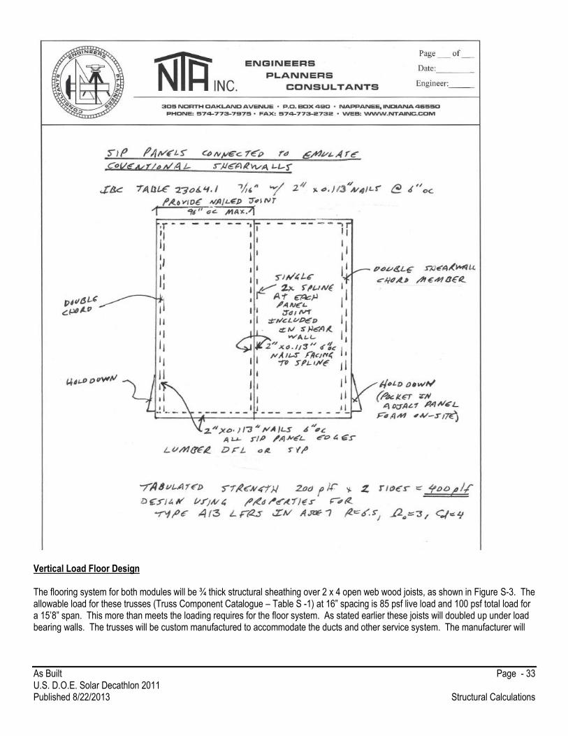
Vertical Load Floor Design The flooring system for both modules will be ¾ thick structural sheathing over 2 x 4 open web wood joists, as shown in Figure S-3. The allowable load for these trusses (Truss Component Catalogue – Table S -1) at 16” spacing is 85 psf live load and 100 psf total load for a 15’8” span. This more than meets the loading requires for the floor system. As stated earlier these joists will doubled up under load bearing walls. The trusses will be custom manufactured to accommodate the ducts and other service system. The manufacturer will

As Built Page - 34 U.S. D.O.E. Solar Decathlon 2011 Published 8/22/2013 Structural Calculations
certify the trusses for the above loading. These trusses will also accommodate the load from the load bearing walls from the loft. This will place a 200 lb load from the loft + 12 x 16/12 x 8 (load from wall)= 328 lb, applied at 4.5 ft from the left end. Table S-1 Wood Floor Truss Structural Data

As Built Page - 35 U.S. D.O.E. Solar Decathlon 2011 Published 8/22/2013 Structural Calculations
Figure S-2 Loft Framing Plan
Figure S-3 Floor Framing Plan
The peak connection load on the trusses is 185 psf at 16 inches on center over 12 feet = 185 x 16/12 x 6 = 1480 lb. A Simpson Strong tie U 410 joist hanger – with an allowable capacity of 2015 lb is more than adequate.
Up to 12.25 ft
11ft
Up to 12.25ft
ft
11.8 ft
Load bearing wall

As Built Page - 36 U.S. D.O.E. Solar Decathlon 2011 Published 8/22/2013 Structural Calculations
The vertical load on the steel wide flange beam in-situ will be from the walls (weight – 13 psf average), the roof, floor and deck (it is assumed that the wide flanges will be used to support a section of the decking. If it is assumed that there is a maximum tributary width of 12.25/2 ft. for the floor width and a 4/2 ft. tributary width for the decking (10 psf – assumed DL on the deck with a 100 psf live load), the total uniform loading on the long beams on the long side of the larger module will be a service level load of [12.25’/2 x ( 21 +50 psf) + 13 psf ( 14.6’) + 200 lb/1.33’ + 1900/8’ + 50 lb/ft ]= 1.1 kips/ft This assumes that the column load on the beam can be modeled as a uniform load. This assumption will be discussed further later in this section. If the beams are assumed to span simply supported from the center of the footings, the allowable moment capacity of the beam (as per the AISC manual) is 179 ft.kips. This would allow a footing spacing based on flexure in the beam of 179 = 1.10 (L)2/8 , or a maximum span of 36 feet. To control deflections and footing loads, the footings will be spaced at maximum of 16 ft centers. This keeps the bearing load to at most 1.1 x 16 = 17.6 kips. Note that this spacing allows for increases in footing loads due to beam continuity and ensures that the concentrated loads from the roof trusses to not produce moments, or shear in excess on the steel beam. Even if the column load is applied in the center of a 16 ft span and there were simple supports, the moments produced by the column loads would be 1900 (16/4) = 7.7 kips.ft and well below capacity, even if added to the other loads. The small module will use the same chassis. This by inspection will be adequate. Further, to facilitate transportation. All beams will be welded together at the joint to form a full moment connection. This will be done by coping back the upper and lower flanges of the short (12 ft) beams and connect the beam webs and flanges with full penetration welds.
Footings Assuming a 2 x 2 foot footing, at a 16 ft spacing this would produce a bearing pressure of 4400 psf < 6000 psf. It is assumed that the bearing pressure allowable is still 6000 psf. The footings will be 6 to 8” in thickness and reinforced with 3 # 4 rebar (each way) to reduce cracking and for handling. There will be a three bolt and nut system that will allow a plate to be brought into contact with the bottom of the steel beam. This system will be used to adjust the level of the home and to provide some lateral connection between the beam and footing. These plates and bolts will resist a maximum of 17. 6 kips. The plate will be 12” x 8” x 3/4” A 36 plate. If it is assumed that the beam bearing load is applied at the beam web and the bolts do not exceed a 5 inches spacing, the peak bending stress in the plate is S = 12 (.75)2/6 =1.125 in3 Stress = 17.6 kips (5”)/(4(1.125)) = 19.6 ksi Allowable bending stress = 36/1.67 =21.6 ksi, Therefore OK For bearing on the concrete assume 4000 psi concrete and a peak loading on the bolt to one side of the plate = 17.6/2 = 8.8 kips Assuming 1.2 D + 1.6 L governs (use an average load factor of 1.4 load factor) this puts a factored load of 8.8 x 1.5 =13.5 kips Assume bearing plates of 2 x 2 x ½ with a ¾ + 1/16” hole
Capacityfc(0.85) f’c (Area)= 0.6 x 2 x 4000 x 0.85 x (4 – 0.66)/1000 = 13.6 kips - OK Note a ¾” A 307 bolt or Rod has an allowable tension load of 9.94 kips.
As Built Page - 37 U.S. D.O.E. Solar Decathlon 2011 Published 8/22/2013 Structural Calculations
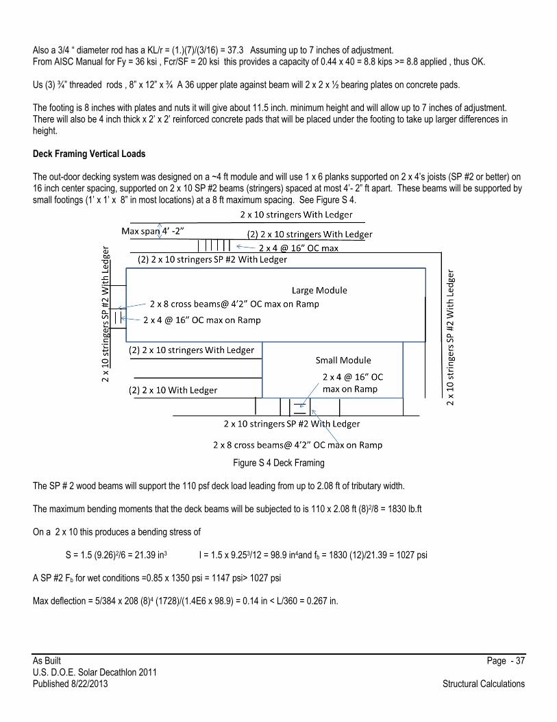
Also a 3/4 “ diameter rod has a KL/r = (1.)(7)/(3/16) = 37.3 Assuming up to 7 inches of adjustment. From AISC Manual for Fy = 36 ksi , Fcr/SF = 20 ksi this provides a capacity of 0.44 x 40 = 8.8 kips >= 8.8 applied , thus OK. Us (3) ¾” threaded rods , 8” x 12” x ¾ A 36 upper plate against beam will 2 x 2 x ½ bearing plates on concrete pads. The footing is 8 inches with plates and nuts it will give about 11.5 inch. minimum height and will allow up to 7 inches of adjustment. There will also be 4 inch thick x 2’ x 2’ reinforced concrete pads that will be placed under the footing to take up larger differences in height. Deck Framing Vertical Loads The out-door decking system was designed on a ~4 ft module and will use 1 x 6 planks supported on 2 x 4’s joists (SP #2 or better) on 16 inch center spacing, supported on 2 x 10 SP #2 beams (stringers) spaced at most 4’- 2” ft apart. These beams will be supported by small footings (1’ x 1’ x 8” in most locations) at a 8 ft maximum spacing. See Figure S 4.
Figure S 4 Deck Framing
The SP # 2 wood beams will support the 110 psf deck load leading from up to 2.08 ft of tributary width. The maximum bending moments that the deck beams will be subjected to is 110 x 2.08 ft (8)2/8 = 1830 lb.ft On a 2 x 10 this produces a bending stress of S = 1.5 (9.26)2/6 = 21.39 in3 I = 1.5 x 9.253/12 = 98.9 in4and fb = 1830 (12)/21.39 = 1027 psi A SP #2 Fb for wet conditions =0.85 x 1350 psi = 1147 psi> 1027 psi Max deflection = 5/384 x 208 (8)4 (1728)/(1.4E6 x 98.9) = 0.14 in < L/360 = 0.267 in.

As Built Page - 38 U.S. D.O.E. Solar Decathlon 2011 Published 8/22/2013 Structural Calculations
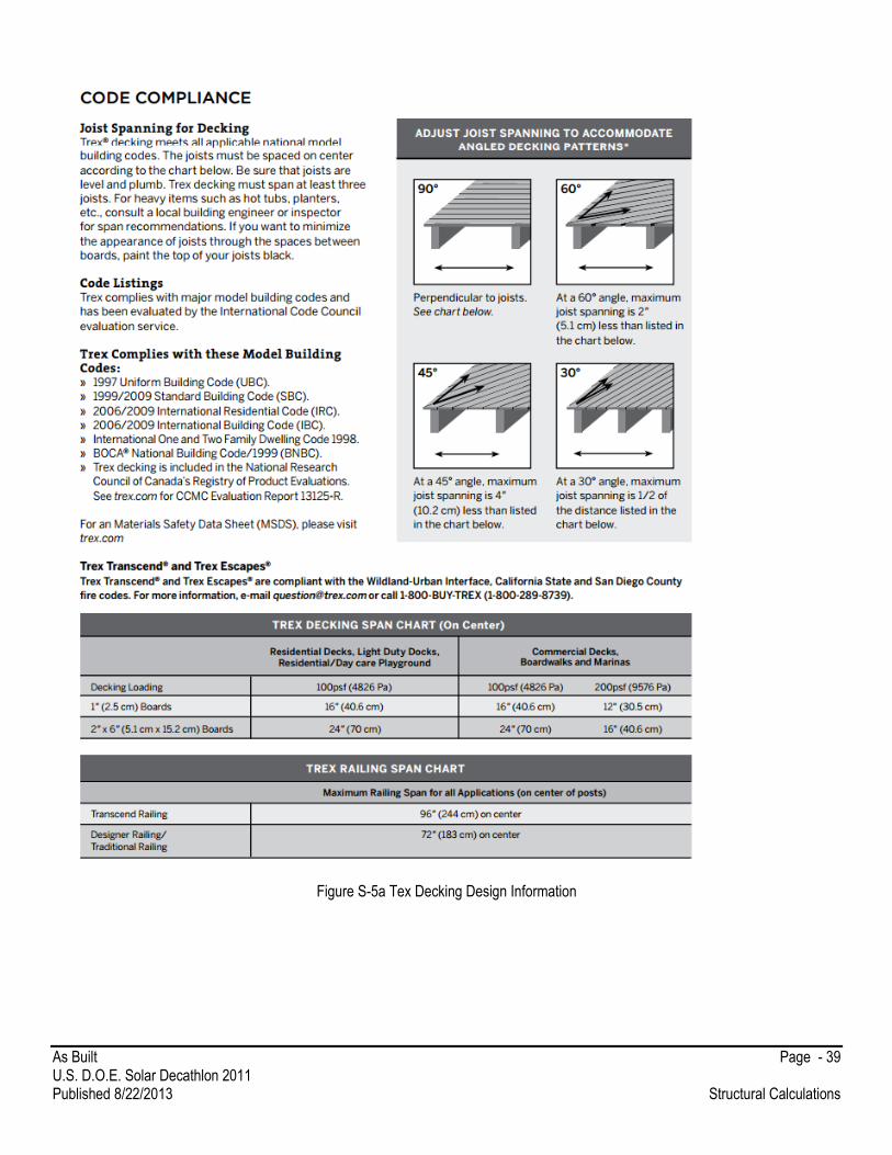
OK in shear by inspection. A ledger will be nailed to the side of the 2 x 10 to provide the 2 x 4 deck joist support and nails as required by IRC 2012 for Ledger supports. The 2 x 4 joist span to the center of the ledger is 4’-1”. This produces a maximum moment of 110 x 16/12(4.08)2/ 8 = 305 lb.ft The bending stress for a 2 x 4 is = fb = 305(12)/3.06 = 1196 psi. This is less than the 0.85 x 1350 x 1.15 (repetitive member) = 1320 psi Note the 2 x 4 could be spaced out to about 13.5” if their span is under 48”. The TEX Decking can span up to 16 inches for a superimposed live load of 100 psf so the 16 in. spacing of the 2 x 4 joists is adequate. See Figure S -5. As an alternative, check if wood deck planks can span 12” spacing of deck floor joists.
The maximum moment on each 5” wide plank = 110 x 5/12 (1)2/8 *12 = 68.75 lb.in For a 1.25” x 5.00 deck plank , S = 5 (1.25)2/6 = 1.30 in3
This produces a maximum bending stress of 68.8/1.3= 53.0 psi any grade of wood would be adequate. By inspection shear and deflection are also adequate.
On the ramps the direction of the planks is shifted this requires that 2 x 4’s run parallel to the 2 x 10 stringers. There will be 2 x 8 beams spaced at a maximum of 4’-2”. This will produce a peak bending stress = (110 x 4.17) (4.17)2/8 x 12/13.14 = 911 psi This is lower that SP # allowable, Fb, so is OK. Shear is 1.5 x 4.17 x 4.17/2x 110/10.88 = 131 < 175 x .97 = 170 psi OK in Shear. Deflections are OK as well by inspection. NOTE LIMITS ON SPACING OF PAVEMENT ANCHORS HAVE NOT BEEN ADDRESSED BY THE DESIGN AND WILL REQUIRE UPDATING. IT IS EXPECTED THAT THE SAME CHANNELS WILL BE USED AND SIMPLY INCREASE THE LENGTH OF THE CHANNELS TO ENSURE A 2 FT SPACING.
As Built Page - 39 U.S. D.O.E. Solar Decathlon 2011 Published 8/22/2013 Structural Calculations
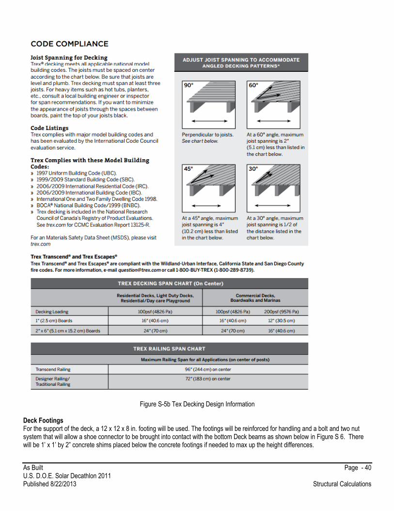
Figure S-5a Tex Decking Design Information
As Built Page - 40 U.S. D.O.E. Solar Decathlon 2011 Published 8/22/2013 Structural Calculations
Figure S-5b Tex Decking Design Information
Deck Footings For the support of the deck, a 12 x 12 x 8 in. footing will be used. The footings will be reinforced for handling and a bolt and two nut system that will allow a shoe connector to be brought into contact with the bottom Deck beams as shown below in Figure S 6. There will be 1’ x 1’ by 2” concrete shims placed below the concrete footings if needed to max up the height differences.
As Built Page - 41 U.S. D.O.E. Solar Decathlon 2011 Published 8/22/2013 Structural Calculations
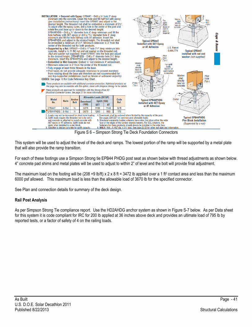
Figure S 6 – Simpson Strong Tie Deck Foundation Connectors
This system will be used to adjust the level of the deck and ramps. The lowest portion of the ramp will be supported by a metal plate that will also provide the ramp transition. For each of these footings use a Simpson Strong tie EPB44 PHDG post seat as shown below with thread adjustments as shown below. 4” concrete pad shims and metal plates will be used to adjust to within 2” of level and the bolt will provide final adjustment. The maximum load on the footing will be (208 +9 lb/ft) x 2 x 8 ft = 3472 lb applied over a 1 ft2 contact area and less than the maximum 6000 psf allowed. This maximum load is less than the allowable load of 3670 lb for the specified connector. See Plan and connection details for summary of the deck design. Rail Post Analysis
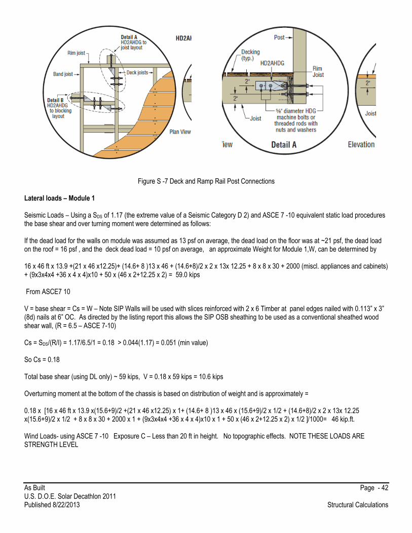
As per Simpson Strong Tie compliance report. Use the HD2AHDG anchor system as shown in Figure S-7 below. As per Data sheet for this system it is code compliant for IRC for 200 lb applied at 36 inches above deck and provides an ultimate load of 795 lb by reported tests, or a factor of safety of 4 on the railing loads.
As Built Page - 42 U.S. D.O.E. Solar Decathlon 2011 Published 8/22/2013 Structural Calculations
Figure S -7 Deck and Ramp Rail Post Connections
Lateral loads – Module 1 Seismic Loads – Using a SDS of 1.17 (the extreme value of a Seismic Category D 2) and ASCE 7 -10 equivalent static load procedures the base shear and over turning moment were determined as follows: If the dead load for the walls on module was assumed as 13 psf on average, the dead load on the floor was at ~21 psf, the dead load on the roof = 16 psf , and the deck dead load = 10 psf on average, an approximate Weight for Module 1,W, can be determined by 16 x 46 ft x 13.9 +(21 x 46 x12.25)+ (14.6+ 8 )13 x 46 + (14.6+8)/2 x 2 x 13x 12.25 + 8 x 8 x 30 + 2000 (miscl. appliances and cabinets) + (9x3x4x4 +36 x 4 x 4)x10 + 50 x (46 x 2+12.25 x 2) = 59.0 kips From ASCE7 10 V = base shear = Cs = W – Note SIP Walls will be used with slices reinforced with 2 x 6 Timber at panel edges nailed with 0.113” x 3” (8d) nails at 6” OC. As directed by the listing report this allows the SIP OSB sheathing to be used as a conventional sheathed wood shear wall, (R = 6.5 – ASCE 7-10) Cs = SDS/(R/I) = 1.17/6.5/1 = 0.18 > 0.044(1.17) = 0.051 (min value) So Cs = 0.18 Total base shear (using DL only) ~ 59 kips, V = 0.18 x 59 kips = 10.6 kips Overturning moment at the bottom of the chassis is based on distribution of weight and is approximately = 0.18 x [16 x 46 ft x 13.9 x(15.6+9)/2 +(21 x 46 x12.25) x 1+ (14.6+ 8 )13 x 46 x (15.6+9)/2 x 1/2 + (14.6+8)/2 x 2 x 13x 12.25 x(15.6+9)/2 x 1/2 + 8 x 8 x 30 + 2000 x 1 + (9x3x4x4 +36 x 4 x 4)x10 x 1 + 50 x (46 x 2+12.25 x 2) x 1/2 ]/1000= 46 kip.ft. Wind Loads- using ASCE 7 -10 Exposure C – Less than 20 ft in height. No topographic effects. NOTE THESE LOADS ARE STRENGTH LEVEL

As Built Page - 43 U.S. D.O.E. Solar Decathlon 2011 Published 8/22/2013 Structural Calculations
Use the simplified procedures in Chapter 28 for Simple Diaphragms Enclosed Buildings less than 60 ft in height. This is for the main Force Resisting System Design. As per Figure 28.6-1 of ASCE 7 (see Figure S 8 below) From this section and assuming a 28.5 degree roof pitch (for the main Module – use 25 degrees, this is conservative), the pressure in each area for roof and walls is as follows: A = 24.1 psf, B = 3.9 psf, C = 17.4 psf D = 4.0 psf , E = -10.7 psf F = -14.6 psf G = -7.7 psf and h = -11.7 psf Note over hangs have a pressure of -19.9 psf near corners and -17.0 psf away from corners
Note mean Roof height = 10 + 16.67 / 2 = 13.35 ft. Also note that the Height adjustment factor, is = 1.21 (for h = 15 ft). This increases all the listed pressures by a factor of 1.21. The “a” distance is the least of 0.1 (26 ft – modules together) = 2.6 ft or 0.4 (10+16.67)/2 = 5.33 ft a = 2.6 ft. Note this distance meets code minimums. For a wind from the north the resulting wind pressures on the roof and walls are as shown in Figure S 9. This is the critical direction for the Main lateral wind load resisting system. The pressure on these panels was adjusted for height and exposure. If we assume the Wind is from the North and applied to the north face of Module 1. The SIP panels will span from the floor to the top plate. The 29.1 psf pressure applied to the wall at the corners will be assumed to be applied to the 7.5 section between the edge trusses and the 20.7 psf uplift pressure applied to the roof surface. If it is assumed that the wind load on the front wall is transferred to the top of each sip panel at approximately 8 ft above the floor, the total uniform load applied to the top Plate is 8 x 29.2/2 = 116.8 lb/ft. This load can be conservatively assumed to be applied to the entire 7.5 ft. section near the edge of the module. If it’s assumed that the top plate carries this load and spans between the lower cords of the roof trusses the beam moment is = 116.8 x (7.5) 2/ 8 = 821.251b/ft. Assuming a 2 x 6, S = 7.56 in3, fb = M/S = 1304 psi This is for strength level loads to convert this to ASD level loads as Per ASCE 7 – 10 by 0.6W = 70.1 lb/ft and this would produce peak bending stresses of = 782 psi. Assuming dry conditions this is much less than the allowable bending stress for even a SPF #2 (850 psi) which is the minimum grade allowed by code. A single 2 x6 SP #2 would be ok. Away from the corners, the load is less but the span is 8 ft. The load is: 20.7 x 8/2=82.8 lb/ft. This produces a peak moment of only 662.5 lb. ft, which is less critical that that addressed earlier. The peak reactions at the bottom of the truss from each side is 2nd truss form west and east walls = 82.8 x 8/2 +116.8 x 7.5 /2= 769.2 lb The top sections in the clerestory have the SIP panels spanning horizontal between the end vertical truss members. This produces a uniform load on the vertical truss elements of: 20.7 x 8/2 + 29.2 x 7.5/2=192.3 lb/ft By inspection the 2 vertical, 2 x 6’s are adequate for this loading and will be checked under combined loading using computer analysis software.

As Built Page - 44 U.S. D.O.E. Solar Decathlon 2011 Published 8/22/2013 Structural Calculations
Note as an alternative the SIP panels can span vertically and connect to the top plate of the lower wall and to the SIP Roof panel at the top. Fasten these panels as Required by the IRC for SIP panels.
Figure S 8 –ASCE 7 – 10 Wind Load Distributions

As Built Page - 45 U.S. D.O.E. Solar Decathlon 2011 Published 8/22/2013 Structural Calculations
Figure S – 9 Wind Load Distribution on Main Module.
If the trusses are assumed to transfer the wall wind loads to the SIPS panels acting as a diaphragm through clip angles attached to the diaphragm OSB at the purlin splices, the total shear to be transferred at each truss will be at most: The Joist point reaction of (769.2 + 6.6 (192.3 lb/ft)) = 2040 lb. Resolving this to the roof angle = 13.9/12.25 x 2040 = 2313 lb A Simpson Strong Tie A34 Angle with 8d nails. These connectors have an allowable Wind load resistance of (assuming sheathing connection = 515 lb per clip wth 8-8d nails. Note this assumes that there is a sawn timber element on both sides of the clip angle. Fasten SIP panels for uplift as described in IRC 2012. Use 2313 x 0.6 /515 = 4.49 say 5 clips along the upper cord of the truss. Note load is resolved to ASD levels Note that the capacity listed above is for nails totally embedded in framing members. This will not occur on the SIP OSB sheathing. Thermo core, the SIP manufacturer recommends that screws into the SIP sheathing have an allowable capacity of
For this clip use of 4 #10 screws provide a capacity of 460 lb in shear. For this configuration this would suggest that six clips give 2760lb in capacity which is higher than needed. Use six clips with 4- 8d nails on one side and 4 #10 screws on the OSB sheathing side.
2ft
6.60 ft
8 ft

As Built Page - 46 U.S. D.O.E. Solar Decathlon 2011 Published 8/22/2013 Structural Calculations
The total shear from wind loads due to the suction force on the roof of the roof level can be conservatively calculated as (assuming corner pressure over the entire section): = 13.9 x 46 x17.67 psf = 11,298 lb Note that this must be resolved to a horizontal component by = 11298 x 6.6/13.9 = 5365 lb The diaphragm must also carry the wall loads applied to the trusses. These loads can be idealized as a peak loading of 2313 / ((7.5+8)/2) ft. = 298.4 lb/ft at the top of the roof applied parallel to the roof diaphragm. Over the maximum of a 46 span, a depth of diaphragm of 13.9 ft produces a Diaphragm reaction = 46/2 x 298.5 = 6864 lb And a Peak Diaphragm Moment = 298.5 (46)2/8 = 78,953 lb.ft or for a cord depth of 13.8 ft = 5721 lb Note that a SP #2 2 x 6 member braced at 8 ft has a capacity in excess of 9.1 kips so a 2 x 8 SP#2 will be OK by inspection. Assume the roof Seismic Load = 0.18 [16 x 46 ft x 13.9 + (14.6+ 8 )13 x 46/2 + (14.6+8)/2 x 2 x 13x 12.25/2 + 8 x 8 x 30/2 + 2000]
= 4238 kips Resolving this load to parallel to the diaphragm gives 13.9/12.25 x 4238 lb = 4809 lb. This is split to each side. Total Wind shear along the depth of the diaphragm = 6864 /13.9 = 493 lb/ft Note the seismic loading is less (4809 lb/13.9)x 1/2 = 173 lb/ft These values are less than the capacity listed for 7/`16 OSB STRUCT. I (Sheathing one side) and blocked diaphragms nailed at 6 in OC by 8 d nails 0.8 x 755 = 604 lb/ft for wind (case 4) and 0.8 x 540 = 432 lb/ft for seismic). The SIP panels cannot be used as a diaphragm in Seismic Design Category D, so 2 x 6 ( or 2 x 8) purlins will be inset in the SIP panel to block the interior sheathing. The interior sheathing will be nailed to resist. By nailing this sheathing as described above it will form a diaphragm. The 2 to 1 maximum diaphragm aspect ratio meets code allowed maximums. Note these capacities are strength level so the loads remain unreduced. The floor sheathing and joists also has a diaphragm capacity that exceeds both seismic and wind loading. The steel beam will carry a wind load of 116.3 lb/ ft out of plane strength level wind load (This produced bending about the y axis over a of 46 ft. In addition, there is a combined vertical load dead + live load = 1.1 kips/ ft . This load produces bending about the x axis over a span of 16 ft at maximum. Conservatively assuming simple supports – My max (wind) = 116.3 (46)2/8 = 30,761 lb.ft
Mx max (wind) = 1,100 (16)2/8 = 35,200 lb.ft Mcx = 112 kip.ft Mcy = 21.3/12x50/1.67 = 53.1 kip.ft My/Mcy+ Mx/Mcx = 0.6 (35.2)/53.1 + 30.8/112 = 0.67 < 1.0 therefore OK
The chassis beam can be used to transfer the lateral loads and the floor does not need to form a wood diaphragm.
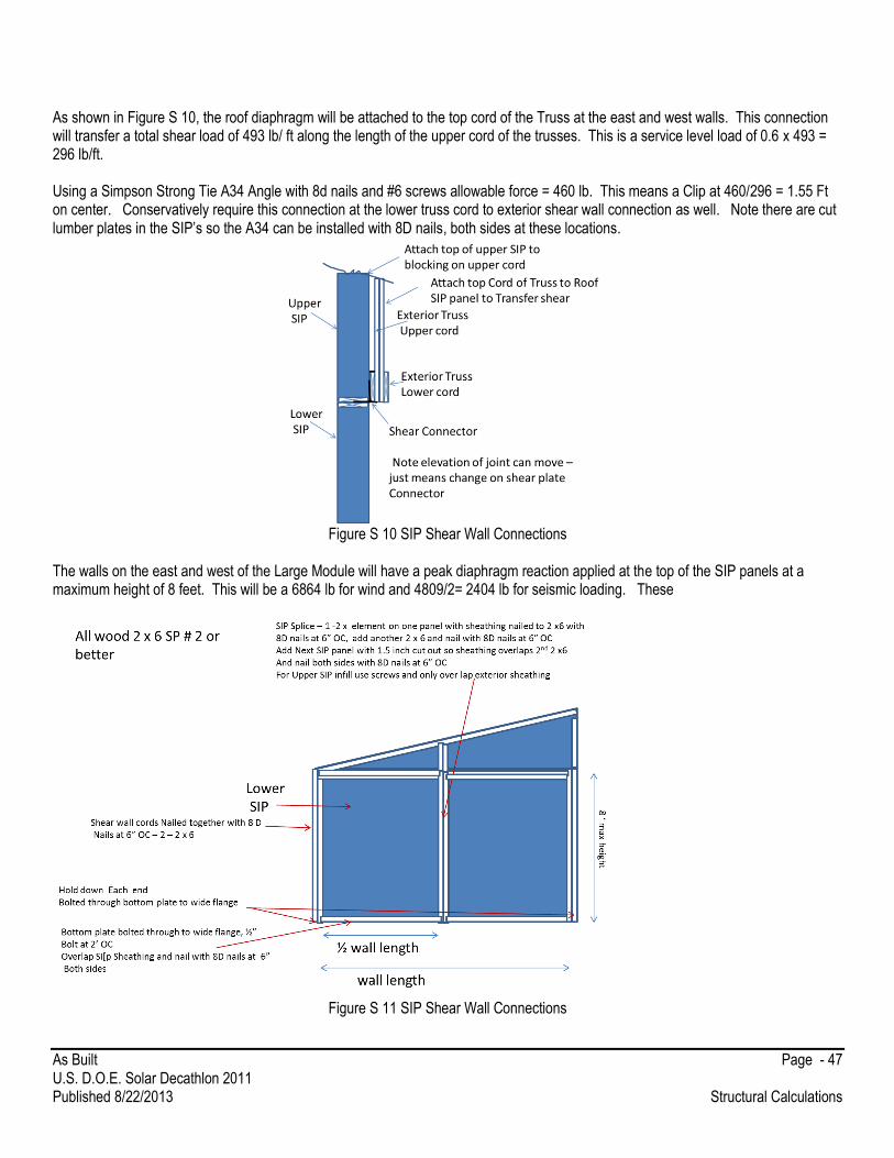
As Built Page - 47 U.S. D.O.E. Solar Decathlon 2011 Published 8/22/2013 Structural Calculations
As shown in Figure S 10, the roof diaphragm will be attached to the top cord of the Truss at the east and west walls. This connection will transfer a total shear load of 493 lb/ ft along the length of the upper cord of the trusses. This is a service level load of 0.6 x 493 = 296 lb/ft. Using a Simpson Strong Tie A34 Angle with 8d nails and #6 screws allowable force = 460 lb. This means a Clip at 460/296 = 1.55 Ft on center. Conservatively require this connection at the lower truss cord to exterior shear wall connection as well. Note there are cut lumber plates in the SIP’s so the A34 can be installed with 8D nails, both sides at these locations.
Figure S 10 SIP Shear Wall Connections
The walls on the east and west of the Large Module will have a peak diaphragm reaction applied at the top of the SIP panels at a maximum height of 8 feet. This will be a 6864 lb for wind and 4809/2= 2404 lb for seismic loading. These
Figure S 11 SIP Shear Wall Connections

As Built Page - 48 U.S. D.O.E. Solar Decathlon 2011 Published 8/22/2013 Structural Calculations
As per the listing report, the 6.5” SIP Wall Panels will be reinforced at each edge with a full depth 2 x 6 member. As show in Figure S -11, the sip panels will be fabricated with a top plate nailed to both sides of the sheathing along one edge. There will also be a base plate that will be bolted to the W 12 x 50 with ½” A 307 bolts at 2’ OC. The panel will have a notch at the base that will be set over the plate and the sheathing will be nailed to the plate on both sides. Another vertical stud will be nailed to the inset wedge stud and bolted through a hold down into the W12 x 50 for over turning resistance. The next panel will be set over the bottom plate and will have the extended stud fit into a notched in the insulations. The panel edges will be nailed both sides with a minimum of 8d nails at 6” O C. This procedure will be repeated for all the SIP panels. This loading of the shear wall produces a peak shear flow of 7093/12.25 = 579 lb/ft for wind loading and a peak shear loading of 2404/12.25 = 196.2 lb/ft. As per NDS 2005 – The shear resistance of one SIP panel (sheathed one side and 8 d nails at 6” OC on edges) gives a capacity of 0.8 (715) = 572 l/ft for wind and 0.8 x 510 = 408 lb/ft for Seismic. Both OK The cord forces on the shear walls with the splices not to exceed 6 ft for wind = 7093 x 8 /6 = 9.45 kips x 0.6 = 5.6 kips < 2 x 6 SP# 2 capacity = 9.1 kips. This governs over seismic. Provide tie downs for 5.6 kips (ASD). The Simpson Strong Tie HUD 5 SDS2.5 will provide a 5.6 kips capacity as shown below. Use a 5/8” dia A 307 bolt with a tension allowable of 10.4 kips drilled though the flange of the Wide flange steel beam. Make sure that there are two studs in connection with the SIP panel behind the connector. From the NDS 2005 ½ “ bolts at 2 ‘ on center gives 680 lb / 2 ft x 1.67 for wind = 5.67 lb/ ft . Provide a ½” bolt at 2ft on center on all sill plates. This governs and will transfer the shear wall shear into the steel beam. In the east and west direction Seismic load will govern. Assume the roof Seismic Load = 0.18 [16 x 46 ft x 13.9 + (14.6+ 8 )13 x 46/2 + (14.6+8)/2 x 2 x 13x 12.25/2 + 8 x 8 x 30/2 + 2000]
= 4238 kips Total seismic shear along the depth of the diaphragm = 4238/46 x 1/2= 46 lb/ft, by inspection, the SIP roof panels have more than enough shear capacity and the end caps will act as cords for this direction with very light loading. Let’s assume that the marriage wall is a 2 x 6 stud wall that is sheathed on at least one side with Struct I OSB 7/16” sheathing Nailed at 6 inches OC with 8 d nails. This gives an 8 ft shear wall section a capacity of 0.8 x 560 x 8 = 3583 lb and the seismic loading is 4238 /2 = 2119 lb. Use 2 clip angles with 3 #8 screws at each lower truss cord. This provides 42 screws to transfer 4238 kip load. This is suggest a load of 101 lb per screw x 0.7 for working load levels. This is OK.
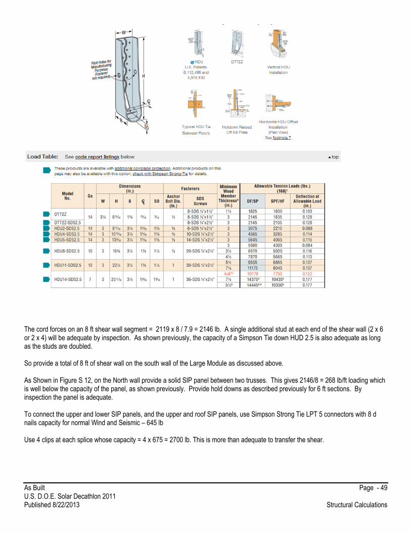
As Built Page - 49 U.S. D.O.E. Solar Decathlon 2011 Published 8/22/2013 Structural Calculations
The cord forces on an 8 ft shear wall segment = 2119 x 8 / 7.9 = 2146 lb. A single additional stud at each end of the shear wall (2 x 6 or 2 x 4) will be adequate by inspection. As shown previously, the capacity of a Simpson Tie down HUD 2.5 is also adequate as long as the studs are doubled. So provide a total of 8 ft of shear wall on the south wall of the Large Module as discussed above. As Shown in Figure S 12, on the North wall provide a solid SIP panel between two trusses. This gives 2146/8 = 268 lb/ft loading which is well below the capacity of the panel, as shown previously. Provide hold downs as described previously for 6 ft sections. By inspection the panel is adequate. To connect the upper and lower SIP panels, and the upper and roof SIP panels, use Simpson Strong Tie LPT 5 connectors with 8 d nails capacity for normal Wind and Seismic – 645 lb Use 4 clips at each splice whose capacity = 4 x 675 = 2700 lb. This is more than adequate to transfer the shear.
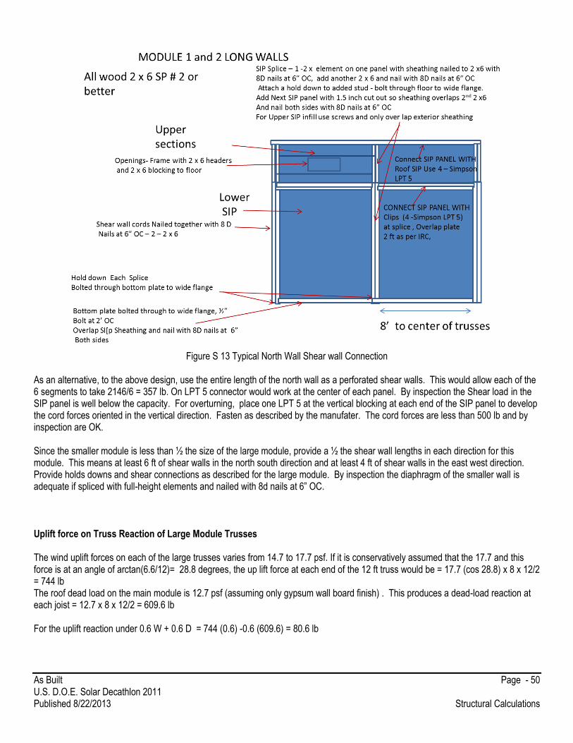
As Built Page - 50 U.S. D.O.E. Solar Decathlon 2011 Published 8/22/2013 Structural Calculations
Figure S 13 Typical North Wall Shear wall Connection
As an alternative, to the above design, use the entire length of the north wall as a perforated shear walls. This would allow each of the 6 segments to take 2146/6 = 357 lb. On LPT 5 connector would work at the center of each panel. By inspection the Shear load in the SIP panel is well below the capacity. For overturning, place one LPT 5 at the vertical blocking at each end of the SIP panel to develop the cord forces oriented in the vertical direction. Fasten as described by the manufater. The cord forces are less than 500 lb and by inspection are OK. Since the smaller module is less than ½ the size of the large module, provide a ½ the shear wall lengths in each direction for this module. This means at least 6 ft of shear walls in the north south direction and at least 4 ft of shear walls in the east west direction. Provide holds downs and shear connections as described for the large module. By inspection the diaphragm of the smaller wall is adequate if spliced with full-height elements and nailed with 8d nails at 6” OC. Uplift force on Truss Reaction of Large Module Trusses The wind uplift forces on each of the large trusses varies from 14.7 to 17.7 psf. If it is conservatively assumed that the 17.7 and this force is at an angle of arctan(6.6/12)= 28.8 degrees, the up lift force at each end of the 12 ft truss would be = 17.7 (cos 28.8) x 8 x 12/2 = 744 lb The roof dead load on the main module is 12.7 psf (assuming only gypsum wall board finish) . This produces a dead-load reaction at each joist = 12.7 x 8 x 12/2 = 609.6 lb For the uplift reaction under 0.6 W + 0.6 D = 744 (0.6) -0.6 (609.6) = 80.6 lb
As Built Page - 51 U.S. D.O.E. Solar Decathlon 2011 Published 8/22/2013 Structural Calculations
Chassis Hold Downs The foundation will have lateral braces and hold downs to resist shear at the floor level and overturning moment. The crawl space will be enclosed with panels and no wind will get under the models. Figure S-13 shows the schematic of the lateral bracing system that will be placed on each side of each module. It is also assumed that the crawl space protection and open plank configuration of the deck does not allow wind pressure build up. By previous calculations, the seismic base shear was 10.6 Kips for the Long module and 46 ‘ kips at the base of the chassis. Assuming the chassis is an average of 1 ft above the ground, increases the overturning moment to 56.6 ‘kips. This will be split ½ to each side of the module = 5.3 kips base shear and 28.3 ’kips. The base shear for the wind load (assuming the corner conditions concentrates at one end) can be determined approximately by Wind base shear =1/2 [20.7 x 16.6’ x 46’ + 13.9 x 46 x 14.2 x 6.6/13.9] + (29.2 – 20.7) x 16.6 x 5.2 + (17.67-14.1)x 5.2 x 13.9 x 6.6/13.9 = 10.92 kips each side This loading is in the North South direction. The overturning moment due to wind each side is 1/2 [20.7 x 16.6’ x 46’ x 16.6/2+ 13.9 x 46 x 14.2 x 6.6/13.9 x 13.3] + (29.2 – 20.7) x 16.6 x 5.2x 16.6/2 + (17.67-14.1)x 5.2 x 13.9 x 6.6/13.9 x13.3 = 103 ’kips The lateral braces in the north south direction must be designed for the critical wind induced base shear at each side of 10.9 kips and an overturning moment of 103. kips. ft. In allowable stress levels, base shear = 0.6 x 10.9 = 6.54 kips, Overturning =0.6 x 103 = 61.8 ‘kips . The braces will be secured to the large module first and before the second module is placed. The second module will be moved into place and the braces on the marriage wall will be attached through the floor in the smaller module. As per information provided by the solar decathlon organizers, the anchors for the homes meet the following specifications:
Solar Decathlon 2013 Anchoring System Design Parameters
Ground anchorage shall be 1" diameter steel stakes driven a minimum of 36" into the existing pavement section consisting of asphalt, macadam and underlying soil.
Assumed pullout design capacity will be 1,250 pounds Assumed shear design capacity will be 1,500 pounds The quantity and placement of anchors shall be such that the combination of Actual Pullout Load/1,250 + Actual Shear
Load/1,500 shall be less than or equal to 1 Anchors must be spaced at least 2 ft on Center and can be headed or threaded. A36 steel rods or better.
Each brace will be assumed to be tension only. Assume the configuration shown in Figure S- 13. The tension in the diagonal rod will be
Tension = 4.86 /4.26 x (base shear = 6.54) = 7.46 kips well below the capacity of a ¾ rod intension (A36 steel)
This puts a combined shear and tension on the channel:
Shear = 6.54 kips and tension = 1.5/4.86x 7.46 = 2.30 kips
If 7 anchors are used, then the combined capacity in shear is 10500 lb and the combined capacity in uplift = 8750 lb
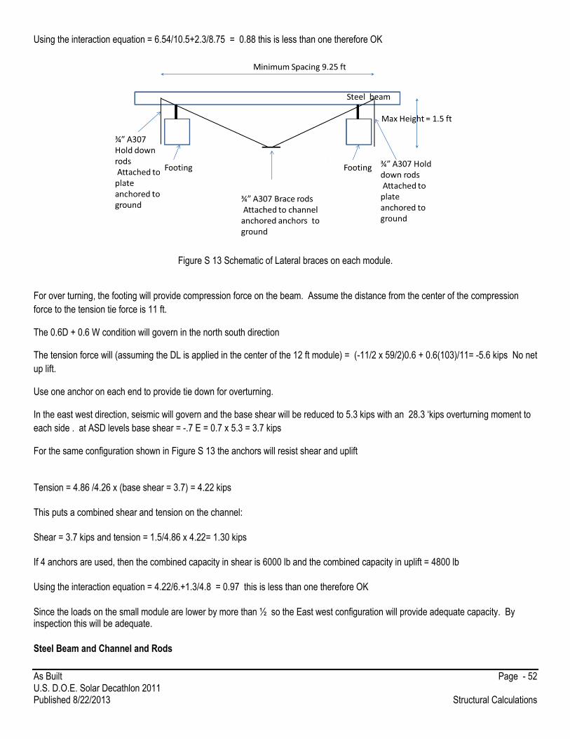
As Built Page - 52 U.S. D.O.E. Solar Decathlon 2011 Published 8/22/2013 Structural Calculations
Using the interaction equation = 6.54/10.5+2.3/8.75 = 0.88 this is less than one therefore OK
Figure S 13 Schematic of Lateral braces on each module. For over turning, the footing will provide compression force on the beam. Assume the distance from the center of the compression
force to the tension tie force is 11 ft.
The 0.6D + 0.6 W condition will govern in the north south direction
The tension force will (assuming the DL is applied in the center of the 12 ft module) = (-11/2 x 59/2)0.6 + 0.6(103)/11= -5.6 kips No net
up lift.
Use one anchor on each end to provide tie down for overturning.
In the east west direction, seismic will govern and the base shear will be reduced to 5.3 kips with an 28.3 ‘kips overturning moment to
each side . at ASD levels base shear = -.7 E = 0.7 x 5.3 = 3.7 kips
For the same configuration shown in Figure S 13 the anchors will resist shear and uplift
Tension = 4.86 /4.26 x (base shear = 3.7) = 4.22 kips
This puts a combined shear and tension on the channel:
Shear = 3.7 kips and tension = 1.5/4.86 x 4.22= 1.30 kips
If 4 anchors are used, then the combined capacity in shear is 6000 lb and the combined capacity in uplift = 4800 lb
Using the interaction equation = 4.22/6.+1.3/4.8 = 0.97 this is less than one therefore OK
Since the loads on the small module are lower by more than ½ so the East west configuration will provide adequate capacity. By inspection this will be adequate.
Steel Beam and Channel and Rods
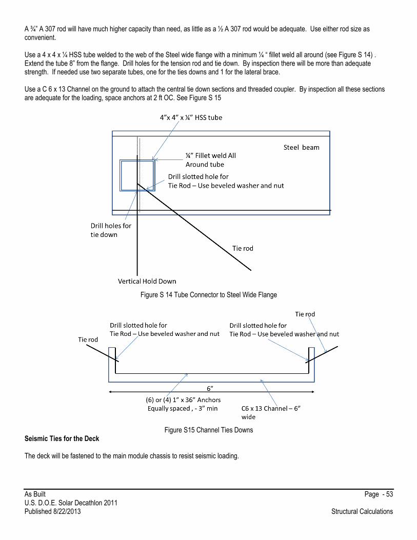
As Built Page - 53 U.S. D.O.E. Solar Decathlon 2011 Published 8/22/2013 Structural Calculations
A ¾” A 307 rod will have much higher capacity than need, as little as a ½ A 307 rod would be adequate. Use either rod size as convenient. Use a 4 x 4 x ¼ HSS tube welded to the web of the Steel wide flange with a minimum ¼ “ fillet weld all around (see Figure S 14) . Extend the tube 8” from the flange. Drill holes for the tension rod and tie down. By inspection there will be more than adequate strength. If needed use two separate tubes, one for the ties downs and 1 for the lateral brace. Use a C 6 x 13 Channel on the ground to attach the central tie down sections and threaded coupler. By inspection all these sections are adequate for the loading, space anchors at 2 ft OC. See Figure S 15
Figure S 14 Tube Connector to Steel Wide Flange
Figure S15 Channel Ties Downs
Seismic Ties for the Deck The deck will be fastened to the main module chassis to resist seismic loading.

As Built Page - 54 U.S. D.O.E. Solar Decathlon 2011 Published 8/22/2013 Structural Calculations
The accelerated weight = 10 psf x 0.18 (assuming the same Seismic Coefficient) say 1.8 lb per square foot of deck.Redcucing this to allowable load level = 0.7 x 1.8 = 1.26 lb / ft2 If the deck extends back 12 ft then the lateral load per length of deck is 12 x 1.26 = 15.1 lb per linear foot of deck. If a 2 x 4 is fixed with a Simpson Strong tie A 35 is applied to select deck modules as shown below
This has an allowable load for Seismic = 380 lb thuss this connection will be needed at 380/15.1 = 25.1 ft. Provide this connector every 24 ft on center. Checking up lift on the Roof Sections and Elements on the Roof The maximum loading force will be for 0.6D + 0.6 W . In the front porch area the dead load = 7 psf and the wind uplift = -32.3 psf Assume that this is applied over the entire area. The net uplift un the roof = 0.6(-32.3+7) = -15.2 psf . This is less than the D+L loading for the roof so elements are OK. Roof rafters have a span of 15 with a 1 ft cantilever. This puts an uplift reaction at the support beam of 16 x 15.2 x 8 /15 = 129.7 lb/ ft For each joist this is an up lift force of 16/12 x 129.7 = 173 lb The Simpson Strong tie A 35 configured as shown below gives a wind capacity of 380 lb. in the A1 direction which is adequate.
For the Post at each end of the beam, the total load = 13.5 / 2 x 129.7 = 875 lb

As Built Page - 55 U.S. D.O.E. Solar Decathlon 2011 Published 8/22/2013 Structural Calculations
Use a Simpson Strong Tie column cap AC4 with 16d nails Both sides . The capacity for wind uplift is 1430 lb, OK.
As an alternative to the above connection, extend the 2 x 6 columns through the Built up beam and bolt the beams. The vertical uplift load does not govern the Dead + Live load will govern in the case, the load would be 1.75 kips (ASD). From NDS 2005 a single ½” diameter Bolt in SP#2 in double shear has a capacity of 550 lb x .7 perpendicular to grain. Assuming the connection will be protected 4 bolts would give 4 x 550 x = 2.2 kips > than 1.75 Therefore OK. At the base of the column, provide a post support as shown not this is the same support as for the decks stringers. Uplift with adhesive is 985 lb, which is acceptable. Anchor each footing to the ground with a single 1 “ anchor (tension capacity =1200 lb). Check the Racking system for the PV panels. The Sunpreme PV panel have a net up lift of 17.67 psf x 0.6 = 10.65 psf. The Schletter PV Rack is attached to the metal roof panels as described in the stamped and sealed drawings as shown below. This configuration is rated for 85 MPH up lift so is sufficient for this application. The rack is also rated up to 20 psf Ground Snow load which is greater than that in Louisville KY.

As Built Page - 56 U.S. D.O.E. Solar Decathlon 2011 Published 8/22/2013 Structural Calculations

As Built Page - 57 U.S. D.O.E. Solar Decathlon 2011 Published 8/22/2013 Structural Calculations
Truss Analysis:
The following Truss was analyzed using STAAD Pro and assuming single 2 x 6 truss members under vertical dead + live loads of 288
lb/ ft on the top elements. Member end forces produce under this load are shown below.
6.6 ft
12.25 ft

As Built Page - 58 U.S. D.O.E. Solar Decathlon 2011 Published 8/22/2013 Structural Calculations
As was shown earlier, a single vertical 2 x 6 will be able to resist the out-of-plane wind loading. Note that deflections are negligible.
The maximum unbraced length of the vertical compression element is less than 7.2 ft. Assume 2 nail laminated Southern Pine # 2 , E
min =580,000 psi. Assume CD = 1.0 , Dry application , normal temps, etc.
319.0
8.
1650/575
8.2
1650/5751
8.2
1650/57516.
psi 574.8 5.1/122.7
000,580822.0F
r,sawn timbe .8 c /
'822.0F
Cexcept allowable Adjusted*
/
2
/1
2
/1
2
2cE
2
mincE
p
*2
**
xxC
x
x
dl
E
F
c
FF
c
FF
c
FFC
p
e
c
ccEccEccEp
Thus, the two 2 x 6’s, nailed together would have an axial capacity (ASD) = .319 x 3 x 5.5 x 1650 = 8680 lb. This is much greater than the 2.2 kips load on Member 7. For the two vertical members in the truss and a lateral load due to the panel reaction from wind is lower than the 20.7 x 8/2 + 29.2 x 7.5/2=192.3 lb/ft. This produces a bending moment of 192.4 x 7.22/8 = 1246.8 lb.ft The capacity of the 2 x 6 = 1650 x 3 x 5.52/6/12 = 2080 lb.ft or fb= M/S = 989.2 psi fc = P/a = 2200 /3(5.5) =133 psi, Fc= 0.319 x 1650 = 516 psi FCE~ = 574psi Look at interaction (133/516)2 + 989.2/[1-133/574]1650 = 0.86 < 1.0 therefore OK. The maximum axial forces on the top cord members are well below the axial capacity of even a 8 ft long single 2 x 6 braced by the SIP panel (9.1 versus 2.7 kips). The bending moment on a (2) 2 x 6 under the 288 lb/ft load over the 7.17 ft span = 288 (7.17)2/8 = 1850 lb.ft The capacity of the 2 x 6 = 1650 x 3 x 5.52/6/12 = 2080 lb.ft or fb= M/S = 147O psi fc = P/a = 2680 /3(5.5) =162 psi, Fc~ 1100 psi FCE~ = 1665 psi Look at interaction (162/1100)2 + 1470/[1-162/1665]1650 = 0.997 < 1.0 therefore OK.
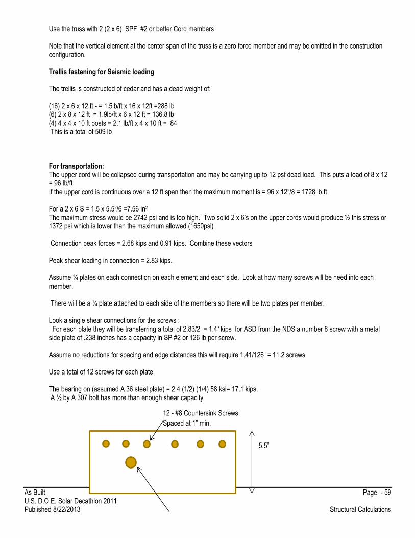
As Built Page - 59 U.S. D.O.E. Solar Decathlon 2011 Published 8/22/2013 Structural Calculations
Use the truss with 2 (2 x 6) SPF #2 or better Cord members Note that the vertical element at the center span of the truss is a zero force member and may be omitted in the construction configuration. Trellis fastening for Seismic loading The trellis is constructed of cedar and has a dead weight of: (16) 2 x 6 x 12 ft - = 1.5lb/ft x 16 x 12ft =288 lb (6) 2 x 8 x 12 ft = 1.9lb/ft x 6 x 12 ft = 136.8 lb (4) 4 x 4 x 10 ft posts = 2.1 lb/ft x 4 x 10 ft = 84 This is a total of 509 lb For transportation: The upper cord will be collapsed during transportation and may be carrying up to 12 psf dead load. This puts a load of 8 x 12 = 96 lb/ft If the upper cord is continuous over a 12 ft span then the maximum moment is = 96 x 122/8 = 1728 lb.ft For a 2 x 6 S = 1.5 x 5.52/6 =7.56 in2 The maximum stress would be 2742 psi and is too high. Two solid 2 x 6’s on the upper cords would produce ½ this stress or 1372 psi which is lower than the maximum allowed (1650psi) Connection peak forces = 2.68 kips and 0.91 kips. Combine these vectors Peak shear loading in connection = 2.83 kips. Assume ¼ plates on each connection on each element and each side. Look at how many screws will be need into each member. There will be a ¼ plate attached to each side of the members so there will be two plates per member. Look a single shear connections for the screws : For each plate they will be transferring a total of 2.83/2 = 1.41kips for ASD from the NDS a number 8 screw with a metal side plate of .238 inches has a capacity in SP #2 or 126 lb per screw. Assume no reductions for spacing and edge distances this will require 1.41/126 = 11.2 screws Use a total of 12 screws for each plate. The bearing on (assumed A 36 steel plate) = 2.4 (1/2) (1/4) 58 ksi= 17.1 kips. A ½ by A 307 bolt has more than enough shear capacity
5.5”
12 - #8 Countersink Screws
Spaced at 1” min.
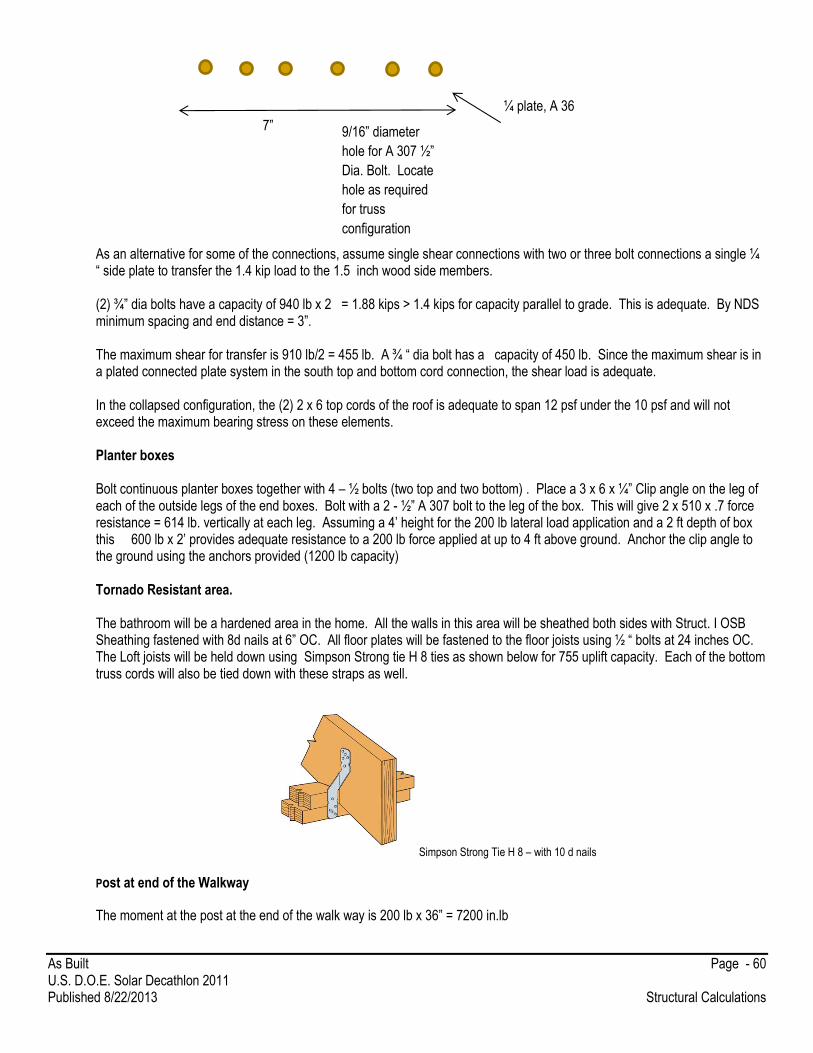
As Built Page - 60 U.S. D.O.E. Solar Decathlon 2011 Published 8/22/2013 Structural Calculations
As an alternative for some of the connections, assume single shear connections with two or three bolt connections a single ¼ “ side plate to transfer the 1.4 kip load to the 1.5 inch wood side members. (2) ¾” dia bolts have a capacity of 940 lb x 2 = 1.88 kips > 1.4 kips for capacity parallel to grade. This is adequate. By NDS minimum spacing and end distance = 3”. The maximum shear for transfer is 910 lb/2 = 455 lb. A ¾ “ dia bolt has a capacity of 450 lb. Since the maximum shear is in a plated connected plate system in the south top and bottom cord connection, the shear load is adequate. In the collapsed configuration, the (2) 2 x 6 top cords of the roof is adequate to span 12 psf under the 10 psf and will not exceed the maximum bearing stress on these elements. Planter boxes Bolt continuous planter boxes together with 4 – ½ bolts (two top and two bottom) . Place a 3 x 6 x ¼” Clip angle on the leg of each of the outside legs of the end boxes. Bolt with a 2 - ½” A 307 bolt to the leg of the box. This will give 2 x 510 x .7 force resistance = 614 lb. vertically at each leg. Assuming a 4’ height for the 200 lb lateral load application and a 2 ft depth of box this 600 lb x 2’ provides adequate resistance to a 200 lb force applied at up to 4 ft above ground. Anchor the clip angle to the ground using the anchors provided (1200 lb capacity) Tornado Resistant area. The bathroom will be a hardened area in the home. All the walls in this area will be sheathed both sides with Struct. I OSB Sheathing fastened with 8d nails at 6” OC. All floor plates will be fastened to the floor joists using ½ “ bolts at 24 inches OC. The Loft joists will be held down using Simpson Strong tie H 8 ties as shown below for 755 uplift capacity. Each of the bottom truss cords will also be tied down with these straps as well.
Simpson Strong Tie H 8 – with 10 d nails
Post at end of the Walkway
The moment at the post at the end of the walk way is 200 lb x 36” = 7200 in.lb
7”
¼ plate, A 36
9/16” diameter
hole for A 307 ½”
Dia. Bolt. Locate
hole as required
for truss
configuration

As Built Page - 61 U.S. D.O.E. Solar Decathlon 2011 Published 8/22/2013 Structural Calculations
Setting this to the moment capacity of a A36 plate: 7200 in lb = S Fb = S x 0.67 x 36,000, thus S required = 0.298 in3.
For a 3.5 “ wide tab or clip angle, the thickness would be 0.71 inches. Use a 6 x 4 x 3/4 angle with two ½ bolts into the post
as shown.
Attach the clip angle to plate that is at least 12 “wide and 7/16” thick (on average) this will give the minimum S required.
Stake the edge of the Plate into the ground with the anchors, one each side.
Safe Room Construction:
The bathroom area is designated as a Tornado shelter area. This area is surrounded on all sides by doubled structural
sheathed walls (7/16 Struct I OSB) nailed with 8 d nails at 6 inches on center that uses the loft floor as a secondary structural
roof and roof diaphragm. The walls have Simpson strong tie hold downs that develop 1875 lb up lift and have ½” bolts at 2 ft
OC in the lower wall plates. The ¾” wood floor loft floor provides a diaphragm and the shear wall resistance will govern and is
10 ft x 560 lb/ft/2x2 = 5600 kips along each 10 ft shear wall. The uplift and cord forces = 8 x 5600/10 = 4800 lb. This exceeds
the up lift capacity of the hold down. The lateral loading is thus limited by this capacity and is 1875/8x10= 234.4 lb/ft. This
corresponds to a lateral load of 1234.4 lb.
The uplift capacity on the loft roof is limited by the S ties (Simpson H 8) on the ceiling joists and there are 4 on each end of the
12 ft joist spans. This corresponds to a 8 x 565 = 4520 lb. Over the 12 x 10 ft loft area this corresponded to an uplift of 37.7
psf. The exterior SIP’s and bullet resistant window will keep the room intact and provide significant resistance to missile
penetration.
The lateral load would be limited by the shear wall capacity to - 1234.4 lb (8/2 x 10/2) = 61.7 psf
The uplift on the ceiling governs and the net wind up lift would be less than 26.9 + 8 psf (½ dead load) = 34.9 psf.
This would correspond to a wind load for Exposure B approximately = 180 MPH (strength level). A much higher load level
than is required for any area in Kentucky or Indiana.
Fall Restraint Connection
The XS Platforms fall restraint system will be used by up two workers on the roof. This system is shown in the health and
safety document. The system will be connected through the roofing system and SIPs to the upper cord of the roof trusses
located about 6 feet from each end of the large module.

As Built Page - 62 U.S. D.O.E. Solar Decathlon 2011 Published 8/22/2013 Structural Calculations
The anchoring point has an ultimate capacity of 20 kN, the manual requires that the anchor points have a capacity of 2000 lb
for two workers.
To extend the 12 mm rod through the exterior upper cord member and through a 1.5 inch bearing plate on the bottom of the
upper cord as shown below:

As Built Page - 63 U.S. D.O.E. Solar Decathlon 2011 Published 8/22/2013 Structural Calculations
The 1.5 x 3” bearing plate has a bearing capacity of 480 x 1.5 x 3” = 2160 lb (assumed Southern Pine # 2). On each truss
both hold down connections will extend out near the plate connections. Since the treaded rod extends out in the plated
connection area, the plates and bolts will transfer the connection to the rest of the truss elements. The uplift capacity of the
connections at the end of the trusses is 1500 lb and combined with the dead load of the roof and truss will exceed the uplift
from the connection. The diaphragm connections and shear walls have enough capacity to carry the shear loading from the
connection.
Use the standard connection to the 7/16” OSB sheets of the SIP panels to develop the needed shear capacity of anchor as
recommended by the manufacturer.
A compliance letter and specification for the system is shown below.

As Built Page - 64 U.S. D.O.E. Solar Decathlon 2011 Published 8/22/2013 Structural Calculations

As Built Page - 65 U.S. D.O.E. Solar Decathlon 2011 Published 8/22/2013 Detailed Water Budget
Detailed Water Budget
Function Water Use (gal) Gallons Events Notes Fire Protection 275 275 1 Drawn from separate tank; closed system, water
level always 275 gal Washer (Clothes) 136 17 8 Dishwasher 25 5 5 Hot Water Draws 240 15 16 Vegetation 324 324 NA Assume daily watering; demand met by the grey-
water recycling system.300 gallons of water each week will allow drip irrigation of 100 plants for 60 minutes twice a week.
Aesthetic Purposes 100 100 NA General cleaning; dinner preparation; movie night; cooking; drinking
Initial Systems Fill 50 50 1 50 Gallon Hot water tank Safety Factor/Testing 300 300 NA Water Feature 50 50 1 Total 1500

As Built Page - 66 U.S. D.O.E. Solar Decathlon 2011 Published 8/22/2013 Summary of Unlisted Electrical Components
Summary of Unlisted Electrical Components
None to report at this time.
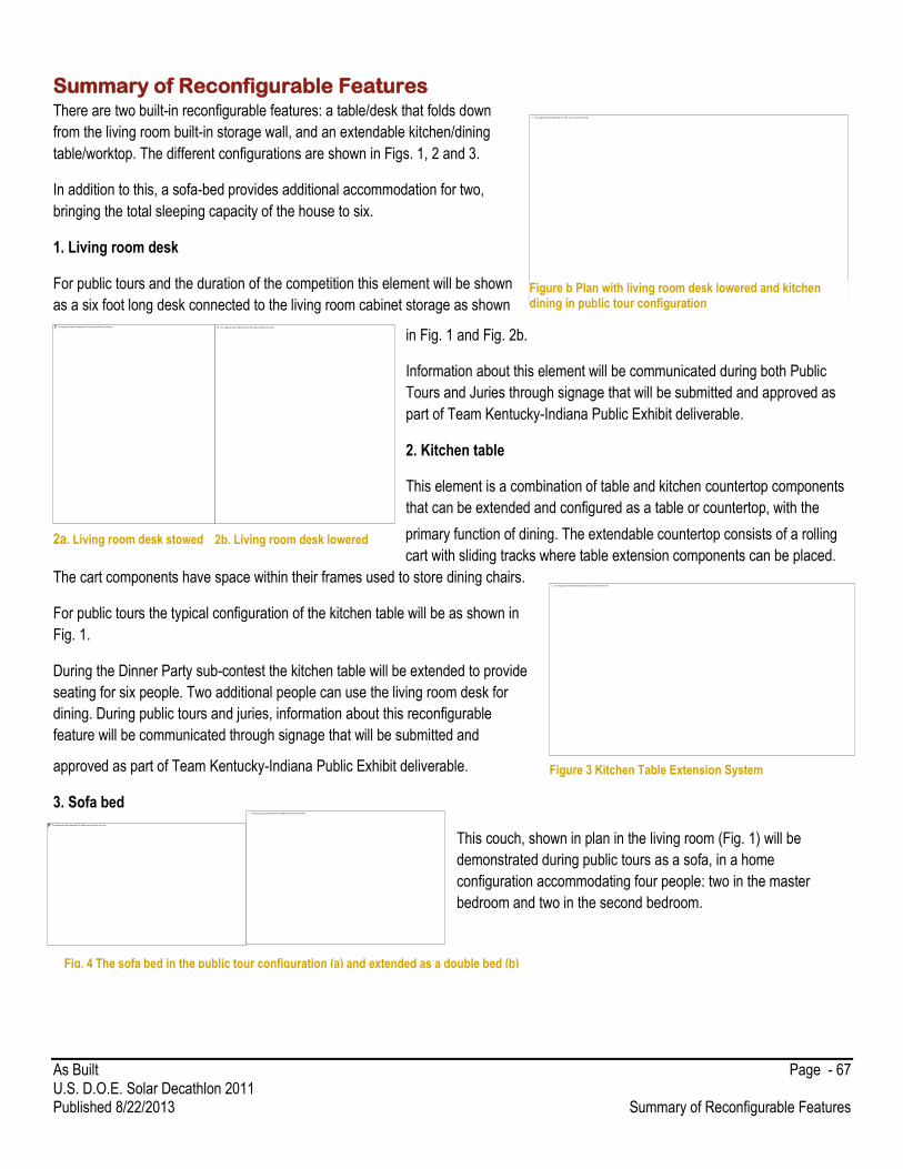
As Built Page - 67 U.S. D.O.E. Solar Decathlon 2011 Published 8/22/2013 Summary of Reconfigurable Features
Summary of Reconfigurable Features There are two built-in reconfigurable features: a table/desk that folds down
from the living room built-in storage wall, and an extendable kitchen/dining
table/worktop. The different configurations are shown in Figs. 1, 2 and 3.
In addition to this, a sofa-bed provides additional accommodation for two,
bringing the total sleeping capacity of the house to six.
1. Living room desk
For public tours and the duration of the competition this element will be shown
as a six foot long desk connected to the living room cabinet storage as shown
in Fig. 1 and Fig. 2b.
Information about this element will be communicated during both Public
Tours and Juries through signage that will be submitted and approved as
part of Team Kentucky-Indiana Public Exhibit deliverable.
2. Kitchen table
This element is a combination of table and kitchen countertop components
that can be extended and configured as a table or countertop, with the
primary function of dining. The extendable countertop consists of a rolling
cart with sliding tracks where table extension components can be placed.
The cart components have space within their frames used to store dining chairs.
For public tours the typical configuration of the kitchen table will be as shown in
Fig. 1.
During the Dinner Party sub-contest the kitchen table will be extended to provide
seating for six people. Two additional people can use the living room desk for
dining. During public tours and juries, information about this reconfigurable
feature will be communicated through signage that will be submitted and
approved as part of Team Kentucky-Indiana Public Exhibit deliverable.
3. Sofa bed
This couch, shown in plan in the living room (Fig. 1) will be
demonstrated during public tours as a sofa, in a home
configuration accommodating four people: two in the master
bedroom and two in the second bedroom.
Figure b Plan with living room desk lowered and kitchen dining in public tour configuration
2a. Living room desk stowed 2b. Living room desk lowered
Figure 3 Kitchen Table Extension System
Fig. 4 The sofa bed in the public tour configuration (a) and extended as a double bed (b)
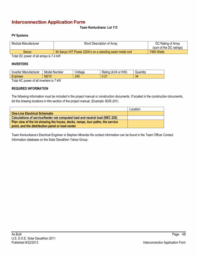
As Built Page - 68 U.S. D.O.E. Solar Decathlon 2011 Published 8/22/2013 Interconnection Application Form
Interconnection Application Form Team Kentuckiana: Lot 113
PV Systems
Module Manufacturer Short Description of Array DC Rating of Array (sum of the DC ratings)
Sanyo 34 Sanyo HIT Power 220A’s on a standing seam metal roof 7480 Watts
Total DC power of all arrays is 7.4 kW
INVERTERS
Inverter Manufacturer Model Number Voltage Rating (kVA or KW) Quantity
Enphase M210 240 0.21 34
Total AC power of all inverters is 7 kW
REQUIRED INFORMATION
The following information must be included in the project manual or construction documents. If located in the construction documents,
list the drawing locations in this section of the project manual. (Example: B3/E-201)
Location
One-Line Electrical Schematic
Calculations of service/feeder net computed load and neutral load (NEC 220)
Plan view of the lot showing the house, decks, ramps, tour paths, the service point, and the distribution panel or load center
Team Kentuckiana’s Electrical Engineer is Stephen Miranda His contact information can be found in the Team Officer Contact
Information database on the Solar Decathlon Yahoo Group.
As Built Page - 69 U.S. D.O.E. Solar Decathlon 2011 Published 8/22/2013 Energy Analysis
Energy Analysis Results and Discussion
1.0 Introduction 1.1 Background
Energy Analysis has been a driving factor in the development and design decision making of the Team Kentuckiana Pheonix House. Students have performed multiple iterations of energy modeling as the design has progressed and the results have guided key decisions in building envelope design, HVAC sizing, and performance optimization with the goal of maximum efficiency in mind. The modeling process has progressed through various stages including:
Building analysis using preliminary home designs to determine optimum insulation values and envelope designs that minimize heating and cooling loads.
Optimum HVAC sizing to meet heating and cooling loads with minimum energy requirements.
Verification of HVAC sizing and energy usage estimates using additional analysis software.
Cost optimization of design choices.
Production of annual energy usage profiles for market and competition locations.
Developing photovoltaic array output estimates and verification using multiple sources.
Analyzing competition performance using provided schedules and competition scenarios.
Parametric runs were used to produce scatter plots of various energy usages to determine optimum design choices. Full building models were also developed to determine how individual design changes would affect the overall energy usage and performance of the house. The use of multiple energy analysis programs allowed the team to utilize various analysis capabilities to determine usage estimate ranges and check for variations between calculations.
2.0 Tools Several energy analysis programs were used to estimate building performance and photovoltaic output. These programs
include: 2.1 Revit Architectural 2013
Revit was used as the primary building design software by the architects of Team Kentuckiana. Geometry from the house design was taken from Revit and used in the creation of energy analysis models.
2.2 BEoptE+ 1.3
The BEopt software provides residential building design analysis capabilities through parametric and optimization runs used to develop whole-house energy saving options. This is a free program that was developed by the National Renewable Energy Laboratory (NREL). BeoptE+ utilizes DOE2.2 and EnergyPlus analysis packages to evaluate energy usage and allows for solar analysis of photovoltaic and solar hot water options.
2.3 eQuest Version 3.64
eQuest is a free energy simulation tool that was developed by the Department of Energy to analyze commercial building energy use. This program is also powered by DOE-2 to complete the energy usage estimates. eQuest allows custom occupancy and HVAC schedules to be created, allowing for the analysis of competition schedules.
2.4 PVWatts
PV Watts was used to determine energy production of photovoltaic cells in both the market and competition locations, as well as determine the optimum angles and output capacity needed to power the house.
2.5 MATLAB R2011a
Data points were taken from PV Watts and used in MATLAB to create graphs of the solar panels’ energy production vs. their angle. The graphs created were visibly simpler

As Built Page - 70 U.S. D.O.E. Solar Decathlon 2011 Published 8/22/2013 Energy Analysis
2.6 Microsoft Office Excel 2010
Results from the energy analysis tools were exported to excel in multiple cases. This allowed for easier analysis and comparison of the data along with the ability to create in depth graphical representations.
3.0 Analysis
3.1 Weather Data All weather data used during energy analysis was provided by the Department of Energy or NREL for use with
analysis software. Weather information from Bowman Field in Louisville, Kentucky was used for market area analysis while California weather zone CZ06RV2 was used for analysis of competition area climate. Weather plots for each location can be found in Figure 1 and Figure 2.
Figure 1. Yearly temperature data for Louisville, KY.
Figure 2. Yearly temperature data for Irvine, CA.
0
10
20
30
40
50
60
70
80
90
100
Jan Feb Mar Apr May Jun Jul Aug Sep Oct Nov Dec
Tem
p (
F)
Avg. High
Avg. Mean
Avg. Low
0
10
20
30
40
50
60
70
80
90
Jan Feb Mar Apr May Jun Jul Aug Sep Oct Nov Dec
Tem
p (
F)
Avg. High
Avg. Mean
Avg. Low
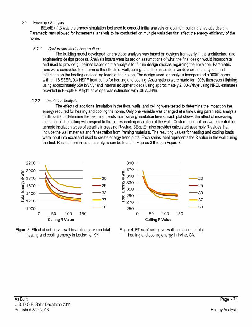
As Built Page - 71 U.S. D.O.E. Solar Decathlon 2011 Published 8/22/2013 Energy Analysis
3.2 Envelope Analysis
BEoptE+ 1.3 was the energy simulation tool used to conduct initial analysis on optimum building envelope design. Parametric runs allowed for incremental analysis to be conducted on multiple variables that affect the energy efficiency of the home.
3.2.1 Design and Model Assumptions The building model developed for envelope analysis was based on designs from early in the architectural and
engineering design process. Analysis inputs were based on assumptions of what the final design would incorporate and used to provide guidelines based on the analysis for future design choices regarding the envelope. Parametric runs were conducted to determine the effects of wall, ceiling, and floor insulation, window areas and types, and infiltration on the heating and cooling loads of the house. The design used for analysis incorporated a 900ft2 home with an 18 SEER, 9.3 HSPF heat pump for heating and cooling. Assumptions were made for 100% fluorescent lighting using approximately 650 kWh/yr and internal equipment loads using approximately 2100kWh/yr using NREL estimates provided in BEoptE+. A tight envelope was estimated with .06 ACH/hr.
3.2.2 Insulation Analysis
The effects of additional insulation in the floor, walls, and ceiling were tested to determine the impact on the energy required for heating and cooling the home. Only one variable was changed at a time using parametric analysis in BEoptE+ to determine the resulting trends from varying insulation levels. Each plot shows the effect of increasing insulation in the ceiling with respect to the corresponding insulation of the wall. Custom user options were created for generic insulation types of steadily increasing R-value. BEoptE+ also provides calculated assembly R-values that include the wall materials and fenestration from framing materials. The resulting values for heating and cooling loads were input into excel and used to create energy trend plots. Each series label represents the R value in the wall during the test. Results from insulation analysis can be found in Figures 3 through Figure 8.
Figure 3. Effect of ceiling vs. wall insulation curve on total
heating and cooling energy in Louisville, KY. Figure 4. Effect of ceiling vs. wall insulation on total
heating and cooling energy in Irvine, CA.
1000
1200
1400
1600
1800
2000
2200
0 50 100 150
To
tal E
ne
rgy
(kW
h)
Ceiling R-Value
20
25
33
37
50 250
270
290
310
330
350
370
390
0 50 100 150
To
tal E
ne
rgy
(kW
h)
Ceiling R-Value
20
25
33
37
50
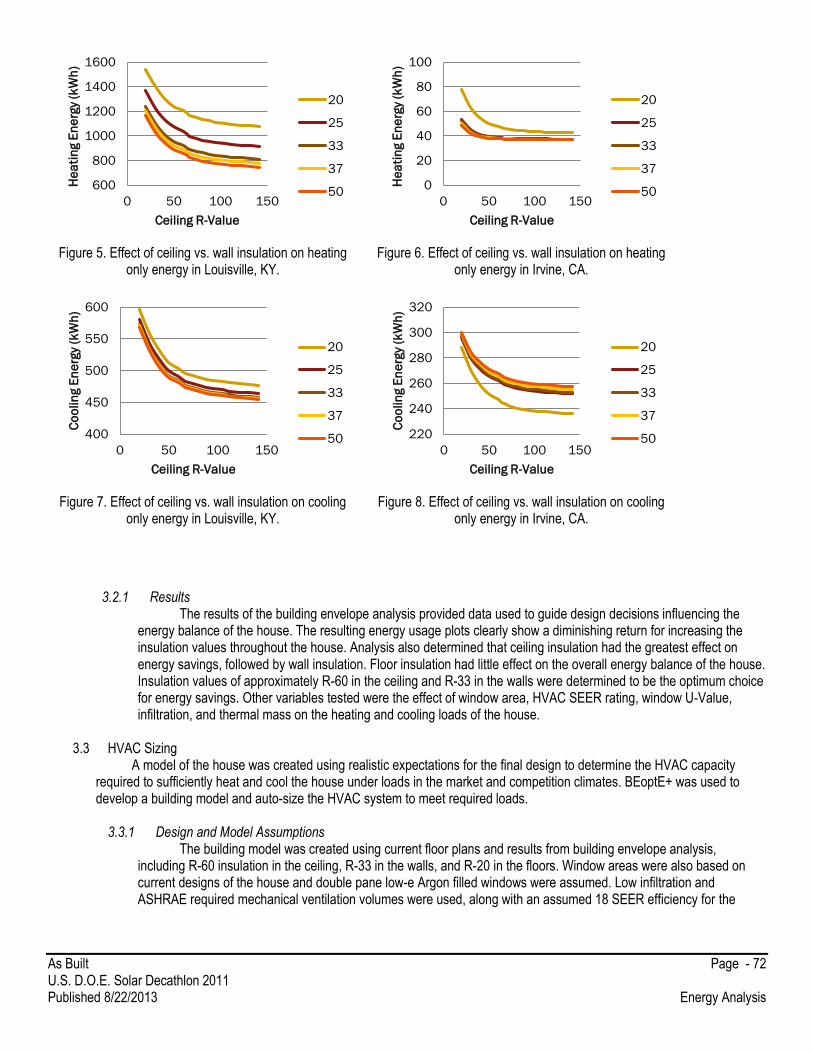
As Built Page - 72 U.S. D.O.E. Solar Decathlon 2011 Published 8/22/2013 Energy Analysis
Figure 5. Effect of ceiling vs. wall insulation on heating
only energy in Louisville, KY. Figure 6. Effect of ceiling vs. wall insulation on heating
only energy in Irvine, CA.
Figure 7. Effect of ceiling vs. wall insulation on cooling
only energy in Louisville, KY. Figure 8. Effect of ceiling vs. wall insulation on cooling
only energy in Irvine, CA.
3.2.1 Results
The results of the building envelope analysis provided data used to guide design decisions influencing the energy balance of the house. The resulting energy usage plots clearly show a diminishing return for increasing the insulation values throughout the house. Analysis also determined that ceiling insulation had the greatest effect on energy savings, followed by wall insulation. Floor insulation had little effect on the overall energy balance of the house. Insulation values of approximately R-60 in the ceiling and R-33 in the walls were determined to be the optimum choice for energy savings. Other variables tested were the effect of window area, HVAC SEER rating, window U-Value, infiltration, and thermal mass on the heating and cooling loads of the house.
3.3 HVAC Sizing
A model of the house was created using realistic expectations for the final design to determine the HVAC capacity required to sufficiently heat and cool the house under loads in the market and competition climates. BEoptE+ was used to develop a building model and auto-size the HVAC system to meet required loads.
3.3.1 Design and Model Assumptions
The building model was created using current floor plans and results from building envelope analysis, including R-60 insulation in the ceiling, R-33 in the walls, and R-20 in the floors. Window areas were also based on current designs of the house and double pane low-e Argon filled windows were assumed. Low infiltration and ASHRAE required mechanical ventilation volumes were used, along with an assumed 18 SEER efficiency for the
600
800
1000
1200
1400
1600
0 50 100 150
He
ati
ng E
ne
rgy
(kW
h)
Ceiling R-Value
20
25
33
37
500
20
40
60
80
100
0 50 100 150
He
ati
ng E
ne
rgy
(kW
h)
Ceiling R-Value
20
25
33
37
50
400
450
500
550
600
0 50 100 150
Co
olin
g E
ne
rgy
(kW
h)
Ceiling R-Value
20
25
33
37
50 220
240
260
280
300
320
0 50 100 150
Co
olin
g E
ne
rgy
(kW
h)
Ceiling R-Value
20
25
33
37
50
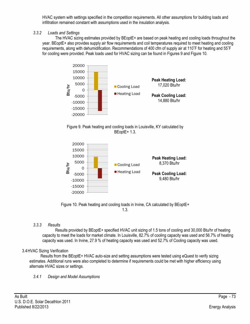
As Built Page - 73 U.S. D.O.E. Solar Decathlon 2011 Published 8/22/2013 Energy Analysis
HVAC system with settings specified in the competition requirements. All other assumptions for building loads and infiltration remained constant with assumptions used in the insulation analysis.
3.3.2 Loads and Settings
The HVAC sizing estimates provided by BEoptE+ are based on peak heating and cooling loads throughout the year. BEoptE+ also provides supply air flow requirements and coil temperatures required to meet heating and cooling requirements, along with dehumidification. Recommendations of 400 cfm of supply air at 110ᵒF for heating and 55ᵒF for cooling were provided. Peak loads used for HVAC sizing can be found in Figures 9 and Figure 10.
Peak Heating Load: 17,020 Btu/hr
Peak Cooling Load:
14,880 Btu/hr
Figure 9. Peak heating and cooling loads in Louisville, KY calculated by BEoptE+ 1.3.
Peak Heating Load: 8,370 Btu/hr
Peak Cooling Load:
9,480 Btu/hr
Figure 10. Peak heating and cooling loads in Irvine, CA calculated by BEoptE+ 1.3.
3.3.3 Results
Results provided by BEoptE+ specified HVAC unit sizing of 1.5 tons of cooling and 30,000 Btu/hr of heating capacity to meet the loads for market climate. In Louisville, 82.7% of cooling capacity was used and 56.7% of heating capacity was used. In Irvine, 27.9 % of heating capacity was used and 52.7% of Cooling capacity was used.
3.4 HVAC Sizing Verification
Results from the BEoptE+ HVAC auto-size and setting assumptions were tested using eQuest to verify sizing estimates. Additional runs were also completed to determine if requirements could be met with higher efficiency using alternate HVAC sizes or settings.
3.4.1 Design and Model Assumptions
-20000
-15000
-10000
-5000
0
5000
10000
15000
20000B
tu/h
r
Cooling Load
Heating Load
-20000
-15000
-10000
-5000
0
5000
10000
15000
20000
Btu
/h
r
Cooling Load
Heating Load
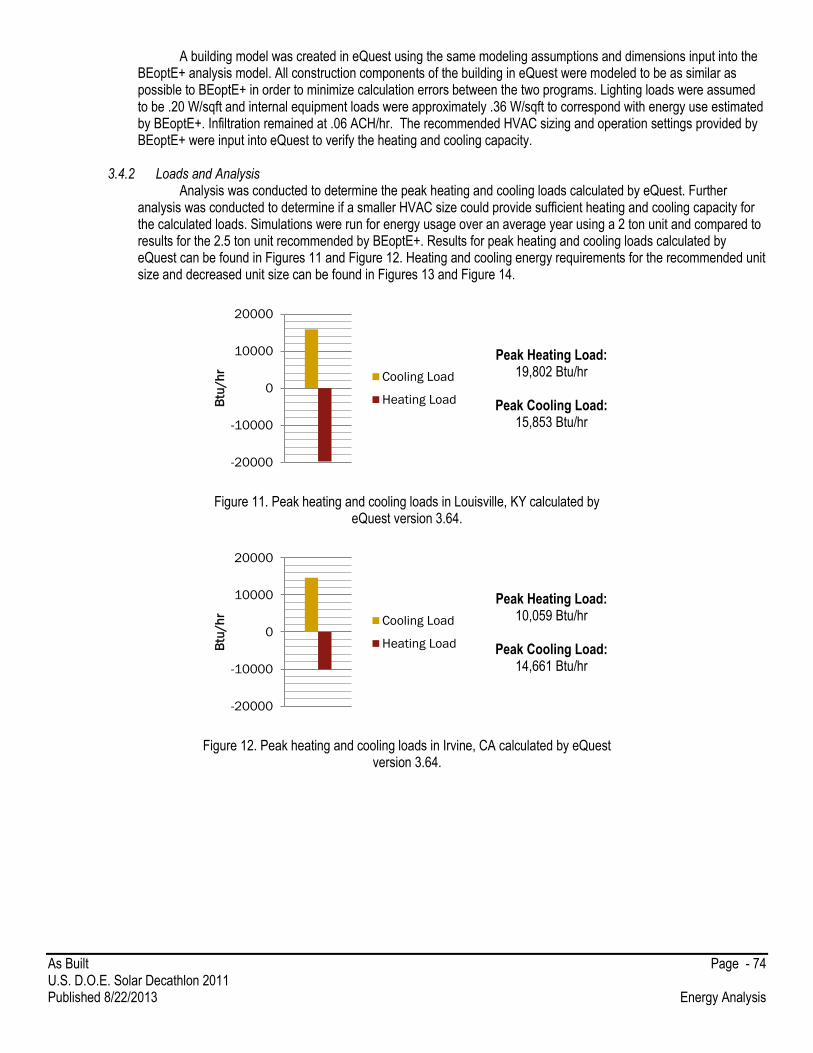
As Built Page - 74 U.S. D.O.E. Solar Decathlon 2011 Published 8/22/2013 Energy Analysis
A building model was created in eQuest using the same modeling assumptions and dimensions input into the BEoptE+ analysis model. All construction components of the building in eQuest were modeled to be as similar as possible to BEoptE+ in order to minimize calculation errors between the two programs. Lighting loads were assumed to be .20 W/sqft and internal equipment loads were approximately .36 W/sqft to correspond with energy use estimated by BEoptE+. Infiltration remained at .06 ACH/hr. The recommended HVAC sizing and operation settings provided by BEoptE+ were input into eQuest to verify the heating and cooling capacity.
3.4.2 Loads and Analysis
Analysis was conducted to determine the peak heating and cooling loads calculated by eQuest. Further analysis was conducted to determine if a smaller HVAC size could provide sufficient heating and cooling capacity for the calculated loads. Simulations were run for energy usage over an average year using a 2 ton unit and compared to results for the 2.5 ton unit recommended by BEoptE+. Results for peak heating and cooling loads calculated by eQuest can be found in Figures 11 and Figure 12. Heating and cooling energy requirements for the recommended unit size and decreased unit size can be found in Figures 13 and Figure 14.
Peak Heating Load: 19,802 Btu/hr
Peak Cooling Load:
15,853 Btu/hr
Figure 11. Peak heating and cooling loads in Louisville, KY calculated by eQuest version 3.64.
Peak Heating Load: 10,059 Btu/hr
Peak Cooling Load:
14,661 Btu/hr
Figure 12. Peak heating and cooling loads in Irvine, CA calculated by eQuest version 3.64.
-20000
-10000
0
10000
20000
Btu
/h
r
Cooling Load
Heating Load
-20000
-10000
0
10000
20000
Btu
/h
r
Cooling Load
Heating Load
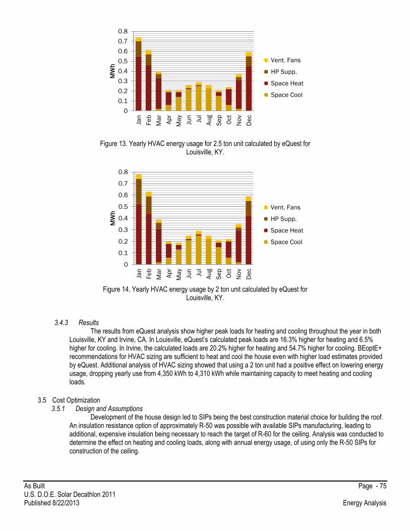
As Built Page - 75 U.S. D.O.E. Solar Decathlon 2011 Published 8/22/2013 Energy Analysis
Figure 13. Yearly HVAC energy usage for 2.5 ton unit calculated by eQuest for Louisville, KY.
Figure 14. Yearly HVAC energy usage by 2 ton unit calculated by eQuest for
Louisville, KY.
3.4.3 Results
The results from eQuest analysis show higher peak loads for heating and cooling throughout the year in both Louisville, KY and Irvine, CA. In Louisville, eQuest’s calculated peak loads are 16.3% higher for heating and 6.5% higher for cooling. In Irvine, the calculated loads are 20.2% higher for heating and 54.7% higher for cooling. BEoptE+ recommendations for HVAC sizing are sufficient to heat and cool the house even with higher load estimates provided by eQuest. Additional analysis of HVAC sizing showed that using a 2 ton unit had a positive effect on lowering energy usage, dropping yearly use from 4,350 kWh to 4,310 kWh while maintaining capacity to meet heating and cooling loads.
3.5 Cost Optimization 3.5.1 Design and Assumptions
Development of the house design led to SIPs being the best construction material choice for building the roof. An insulation resistance option of approximately R-50 was possible with available SIPs manufacturing, leading to additional, expensive insulation being necessary to reach the target of R-60 for the ceiling. Analysis was conducted to determine the effect on heating and cooling loads, along with annual energy usage, of using only the R-50 SIPs for construction of the ceiling.
0
0.1
0.2
0.3
0.4
0.5
0.6
0.7
0.8
Jan
Fe
b
Ma
r
Ap
r
Ma
y
Jun
Jul
Au
g
Se
p
Oct
No
v
De
c
MW
h Vent. Fans
HP Supp.
Space Heat
Space Cool
0
0.1
0.2
0.3
0.4
0.5
0.6
0.7
0.8
Jan
Fe
b
Ma
r
Ap
r
Ma
y
Jun
Jul
Au
g
Se
p
Oct
No
v
De
c
MW
h Vent. Fans
HP Supp.
Space Heat
Space Cool

As Built Page - 76 U.S. D.O.E. Solar Decathlon 2011 Published 8/22/2013 Energy Analysis
3.5.2 Analysis Building HVAC sizing, settings, and envelope were kept constant with previous analysis to determine how the
lower roof insulation affects the energy balance of the house. Both eQuest and BeoptE+ were utilized to determine the effects of lower insulation in the roof. Results for the optimization analysis of roof insulation can be found in Table 1.
Loads
Energy Use
BEoptE+
BEoptE+
Heating Cooling
Heating Cooling Total
R- 47.5 17,320 Btu/hr 15,000 Btu/hr
R- 47.5 2,476 kWh 466 kWh 2942 kWh
R- 57.5 17,080 Btu/hr 14,880 Btu/hr
R- 57.5 2,423 kWh 459 kWh 2882 kWh
eQuest
eQuest
Heating Cooling
Heating Cooling Total
R- 47.5 19,865 Btu/hr 15,869 Btu/hr
R- 47.5 2890 kWh 1,050 kWh 3,940 kWh
R- 57.5 19,802 Btu/hr 15,852 Btu/hr
R- 57.5 2,870 kWh 1,050 kWh 3,920 kWh
Table 1. Effects of lower insulation in Louisville, KY calculated by eQuest and BEoptE+ software.
3.5.3 Results
Results from the roof insulation analysis shows that decreasing the insulation in the roof from R- 57.5 to R-47.5 resulted in increased loads and energy usage per year. BeoptE+ calculated an increase of 2.08% in annual energy usage while eQuest calculated a .51% increase. Both estimates show a low enough energy increase to justify roof construction using only the insulation provided by SIPs panels. Funds saved from less insulation costs will produce better returns on energy savings when invested in other technologies.
3.6 Total Annual Energy Use
3.6.1 Assumptions Assumptions were made for energy use resulting from appliances, plug loads, hot water, and lighting to reflect
likely scenarios for energy usage within the house. Estimates were created from benchmark data along with specifications of equipment that is considered for use in the house.
3.6.2 Analysis
eQuest was used for the analysis of whole house energy usage. Estimates for energy usage can be found in Figure 15, Figure 16, Table 2, and Table 3.

As Built Page - 77 U.S. D.O.E. Solar Decathlon 2011 Published 8/22/2013 Energy Analysis
Figure15. Whole house energy usage in Louisville, Ky provided by eQuest.
Table 2. Energy usage in Louisville, KY.
As Built Page - 78 U.S. D.O.E. Solar Decathlon 2011 Published 8/22/2013 Energy Analysis
Figure 16. Whole house energy usage in Irvine, CA provided by eQuest.
Table 3. Energy use in Irvine, CA.
3.6.3 Results Results from the whole house energy analysis were used to determine the PV array size needed to supply electricity
to the house. Results show that energy use in Louisville is much higher so design choices would be based on estimates for
the market location.
3.7 PV Array sizing

As Built Page - 79 U.S. D.O.E. Solar Decathlon 2011 Published 8/22/2013 Energy Analysis
The PV array providing power to the house was sized using estimates for annual energy consumption provided by BEoptE+ and eQuest analysis software. PV output estimates were produced by PV Watts and BEoptE+ to size the array capacity needed to maintain net zero in both market area and competition climates.
3.7.1 Assumptions
Energy production requirements were based on calculations done via BeOpt and PVWatts. These were assumed to be the yearly energy production requirements to remain at net zero energy for each location.
3.7.2 Analysis
The calculations for the number of solar panels needed came from the expected energy use of 7868.4kWhr/year, with
an additional 20% safety factor bringing that total to 9440kWhr/year. The average amount of solar radiation in a day that will
reach the roof in Louisville is 4.73kW/m2/day (1.44kW/ft2/day). Therefore, 9440kWhr/year divided by 365 days/year, then
divided by the average 4.73kW/m2/day (1.44kW/ft2/day), concludes 5.47m2 (322sq ft.) of roof area will need to be covered by
PV panels in order to meet the house’s requirements to be net-zero.
Station Identification
City: Louisville
State: Kentucky
Latitude: 38.18° N Longitude: 85.73° W Elevation: 149 m PV System Specifications DC Rating: 8.0 kW DC to AC Derate Factor: 0.803 AC Rating: 6.4 kW Array Type: Fixed Tilt Array Tilt: 28.0° Array Azimuth: 180.0°
Table 4. PVWatts data about Louisville, KY
Month Solar Radiation (kWh/m 2/day)
AC Energy (kWh)
Energy Value ($)
1 2.98 604 36.84
2 3.83 697 42.52
3 4.79 931 56.79
4 5.45 988 60.27
5 5.82 1055 64.35
6 6.17 1054 64.29
7 5.97 1046 63.81
8 5.78 1018 62.10
9 5.22 907 55.33
10 4.71 870 53.07
11 3.18 584 35.62
12 2.75 547 33.37
Year 4.73 10302 628.42
Table 5. Data from PV Watts for Louisville, KY

As Built Page - 80 U.S. D.O.E. Solar Decathlon 2011 Published 8/22/2013 Energy Analysis
3.7.3 Results
The house’s net-zero goal, under these calculations, will be met with 24 Sanyo 220w PV panels, along with 24 Enphase M190 microinverters. However, our product selection will be based on the lowest cost and most efficient similarly-rated components. These will take up approximately 350sq ft. of south-facing roof space with a required production capacity of 9440kWhr/year.
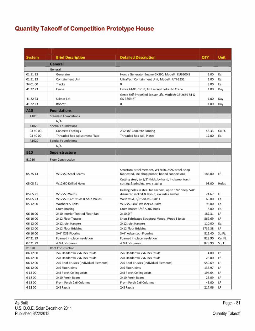
As Built Page - 81 U.S. D.O.E. Solar Decathlon 2011 Published 8/22/2013 Quantity Takeoff
Quantity Takeoff of Competition Prototype House
System
Brief Description Detailed Description QTY Unit
General General
01 51 13 Generator Honda Generator Engine GX390, Model#: EU6500IS 1.00 Ea.
01 51 13 Containment Unit UltraTech Containment Unit, Model#: UTI-2351 1.00 Ea.
34 01 00 Trucks 0 3.00 Ea.
41 22 23 Crane Grove GMK 5120B, All Terrain Hydraulic Crane 1.00 Day
41 22 23 Scissor Lift Genie Self-Propelled Scissor Lift, Model#: GS-2669 RT & GS-3369 RT 1.00 Day
41 22 23 Bobcat 0 1.00 Day
A10 Foundations
A1010 Standard Foundations
N/A
A1020 Special Foundations
03 40 00 Concrete Footings 2'x2'x8" Concrete Footing 45.33 Cu.Ft.
03 40 00 Threaded Rod Adjustment Plate Threaded Rod Adj. Plates 17.00 Ea.
A1020 Special Foundations
N/A
B10 Superstructure
B1010 Floor Construction
05 25 13 W12x50 Steel Beams Structural steel member, W12x50, A992 steel, shop fabricated, incl shop primer, bolted connections 186.00 Lf.
05 05 21 W12x50 Drilled Holes Cutting steel, to 1/2" thick, by hand, incl prep, torch cutting & grinding, excl staging 98.00 Holes
05 05 21 W12x50 Welds Drilling holes in steel for anchors, up to 1/4" deep, 5/8" diameter, incl bit & layout, excludes anchor 24.67 LF
05 05 23 W12x50 1/2" Studs & Stud Welds Weld stud, 3/8" dia x 6-1/8" L 66.00 Ea.
05 12 00 Washers & Bolts W12x50 3/4" Washers & Bolts 98.00 Ea.
Cross Bracing Cross Braces 3/4" A 307 Rods 8.00 Ea.
06 10 00 2x10 Interior Treated Floor Ban 2x10 SYP 187.31 LF
06 10 00 2x12 Floor Trusses Shop-Fabricated Structural Wood, Wood I-Joists 869.69 LF
06 12 00 2x12 Joist Hangers 2x12 Joist Hangers 110.00 Ea.
06 12 00 2x12 Floor Bridging 2x12 Floor Bridging 1739.38 LF
06 10 00 3/4" OSB Flooring 3/4" Advantech Flooring 815.40 Sq.Ft.
07 21 29 Foamed in-place Insulation Foamed in-place Insulation 828.90 Cu. Ft.
07 21 29 4 Mil. Visqueen 4 Mil. Visqueen 828.90 Sq. Ft.
B1020 Roof Construction
06 12 00 2x6 Header w/ 2x6 Jack Studs 2x6 Header w/ 2x6 Jack Studs 4.00 Lf.
06 12 00 2x8 Header w/ 2x6 Jack Studs 2x8 Header w/ 2x6 Jack Studs 28.00 Lf.
06 12 00 2x6 Roof Trusses (Individual Elements) 2x6 Roof Trusses (Individual Elements) 559.69 LF
06 12 00 2x6 Floor Joists 2x6 Floor Joists 133.97 LF
6 12 00 2x8 Porch Ceiling Joists 2x8 Porch Ceiling Joists 194.64 LF
6 12 00 2x10 Porch Beam 2x10 Porch Beam 23.09 LF
6 12 00 Front Porch 2x6 Columns Front Porch 2x6 Columns 46.00 LF
6 12 00 2x8 Fascia 2x8 Fascia 217.06 LF
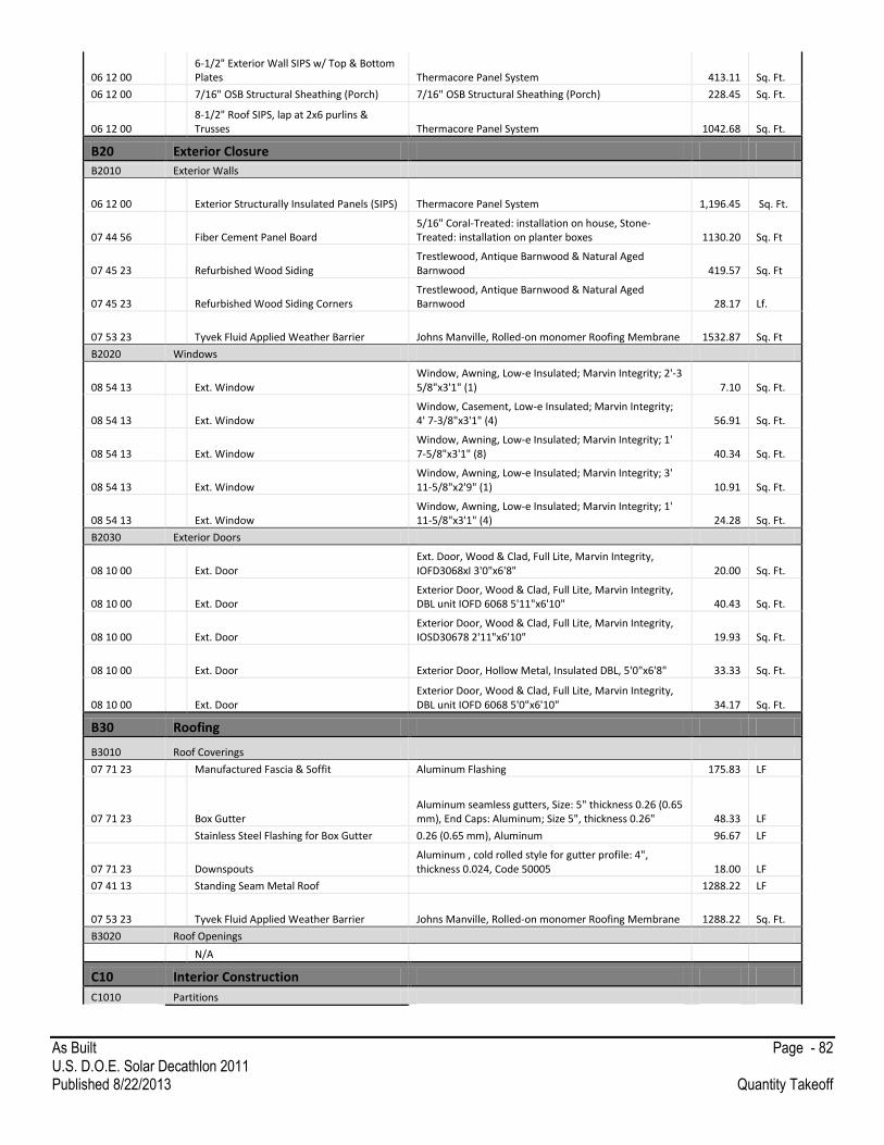
As Built Page - 82 U.S. D.O.E. Solar Decathlon 2011 Published 8/22/2013 Quantity Takeoff
06 12 00 6-1/2" Exterior Wall SIPS w/ Top & Bottom Plates Thermacore Panel System 413.11 Sq. Ft.
06 12 00 7/16" OSB Structural Sheathing (Porch) 7/16" OSB Structural Sheathing (Porch) 228.45 Sq. Ft.
06 12 00 8-1/2" Roof SIPS, lap at 2x6 purlins & Trusses Thermacore Panel System 1042.68 Sq. Ft.
B20 Exterior Closure
B2010 Exterior Walls
06 12 00 Exterior Structurally Insulated Panels (SIPS) Thermacore Panel System
1,196.45 Sq. Ft.
07 44 56 Fiber Cement Panel Board 5/16" Coral-Treated: installation on house, Stone-Treated: installation on planter boxes 1130.20 Sq. Ft
07 45 23 Refurbished Wood Siding Trestlewood, Antique Barnwood & Natural Aged Barnwood 419.57 Sq. Ft
07 45 23 Refurbished Wood Siding Corners Trestlewood, Antique Barnwood & Natural Aged Barnwood 28.17 Lf.
07 53 23 Tyvek Fluid Applied Weather Barrier Johns Manville, Rolled-on monomer Roofing Membrane 1532.87 Sq. Ft
B2020 Windows
08 54 13 Ext. Window Window, Awning, Low-e Insulated; Marvin Integrity; 2'-3 5/8"x3'1" (1) 7.10 Sq. Ft.
08 54 13 Ext. Window Window, Casement, Low-e Insulated; Marvin Integrity; 4' 7-3/8"x3'1" (4) 56.91 Sq. Ft.
08 54 13 Ext. Window Window, Awning, Low-e Insulated; Marvin Integrity; 1' 7-5/8"x3'1" (8) 40.34 Sq. Ft.
08 54 13 Ext. Window Window, Awning, Low-e Insulated; Marvin Integrity; 3' 11-5/8"x2'9" (1) 10.91 Sq. Ft.
08 54 13 Ext. Window Window, Awning, Low-e Insulated; Marvin Integrity; 1' 11-5/8"x3'1" (4) 24.28 Sq. Ft.
B2030 Exterior Doors
08 10 00 Ext. Door Ext. Door, Wood & Clad, Full Lite, Marvin Integrity, IOFD3068xI 3'0"x6'8" 20.00 Sq. Ft.
08 10 00 Ext. Door Exterior Door, Wood & Clad, Full Lite, Marvin Integrity, DBL unit IOFD 6068 5'11"x6'10" 40.43 Sq. Ft.
08 10 00 Ext. Door Exterior Door, Wood & Clad, Full Lite, Marvin Integrity, IOSD30678 2'11"x6'10" 19.93 Sq. Ft.
08 10 00 Ext. Door Exterior Door, Hollow Metal, Insulated DBL, 5'0"x6'8" 33.33 Sq. Ft.
08 10 00 Ext. Door Exterior Door, Wood & Clad, Full Lite, Marvin Integrity, DBL unit IOFD 6068 5'0"x6'10" 34.17 Sq. Ft.
B30 Roofing
B3010 Roof Coverings
07 71 23 Manufactured Fascia & Soffit Aluminum Flashing 175.83 LF
07 71 23 Box Gutter Aluminum seamless gutters, Size: 5" thickness 0.26 (0.65 mm), End Caps: Aluminum; Size 5", thickness 0.26" 48.33 LF
Stainless Steel Flashing for Box Gutter 0.26 (0.65 mm), Aluminum 96.67 LF
07 71 23 Downspouts Aluminum , cold rolled style for gutter profile: 4", thickness 0.024, Code 50005 18.00 LF
07 41 13 Standing Seam Metal Roof 1288.22 LF
07 53 23 Tyvek Fluid Applied Weather Barrier Johns Manville, Rolled-on monomer Roofing Membrane 1288.22 Sq. Ft.
B3020 Roof Openings
N/A
C10 Interior Construction
C1010 Partitions
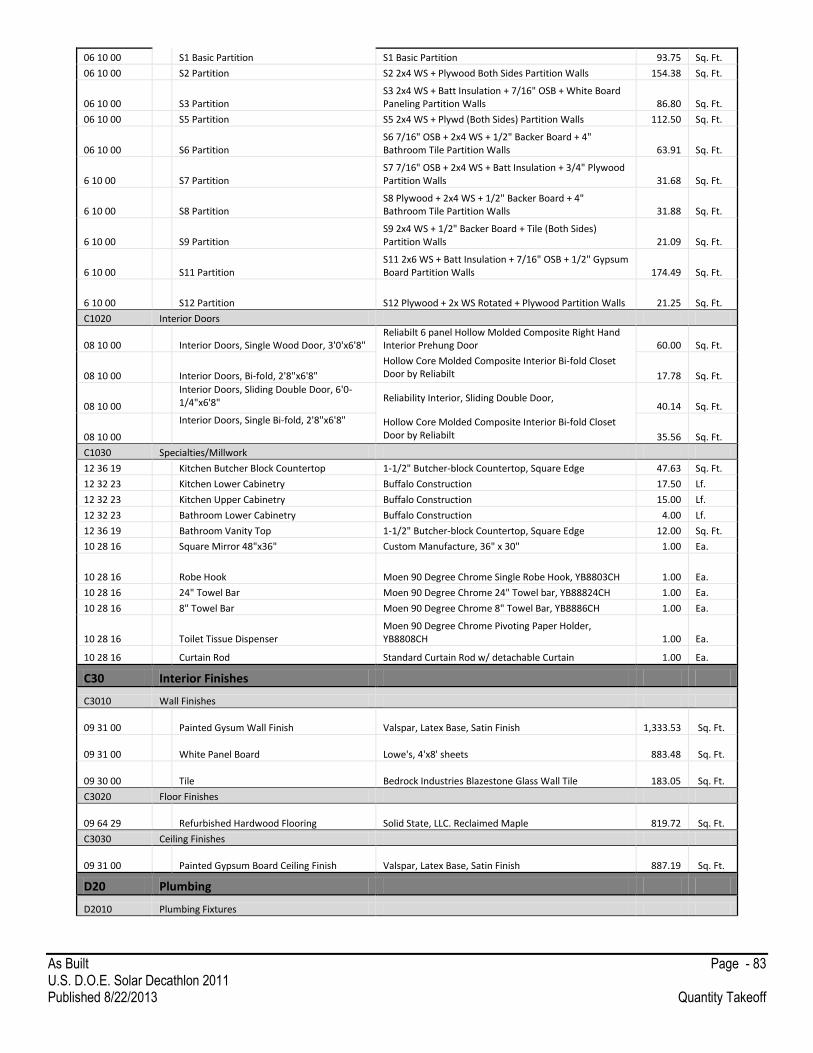
As Built Page - 83 U.S. D.O.E. Solar Decathlon 2011 Published 8/22/2013 Quantity Takeoff
06 10 00 S1 Basic Partition S1 Basic Partition 93.75 Sq. Ft.
06 10 00 S2 Partition S2 2x4 WS + Plywood Both Sides Partition Walls 154.38 Sq. Ft.
06 10 00 S3 Partition S3 2x4 WS + Batt Insulation + 7/16" OSB + White Board Paneling Partition Walls 86.80 Sq. Ft.
06 10 00 S5 Partition S5 2x4 WS + Plywd (Both Sides) Partition Walls 112.50 Sq. Ft.
06 10 00 S6 Partition S6 7/16" OSB + 2x4 WS + 1/2" Backer Board + 4" Bathroom Tile Partition Walls 63.91 Sq. Ft.
6 10 00 S7 Partition S7 7/16" OSB + 2x4 WS + Batt Insulation + 3/4" Plywood Partition Walls 31.68 Sq. Ft.
6 10 00 S8 Partition S8 Plywood + 2x4 WS + 1/2" Backer Board + 4" Bathroom Tile Partition Walls 31.88 Sq. Ft.
6 10 00 S9 Partition S9 2x4 WS + 1/2" Backer Board + Tile (Both Sides) Partition Walls 21.09 Sq. Ft.
6 10 00 S11 Partition S11 2x6 WS + Batt Insulation + 7/16" OSB + 1/2" Gypsum Board Partition Walls 174.49 Sq. Ft.
6 10 00 S12 Partition S12 Plywood + 2x WS Rotated + Plywood Partition Walls 21.25 Sq. Ft.
C1020 Interior Doors
08 10 00 Interior Doors, Single Wood Door, 3'0'x6'8" Reliabilt 6 panel Hollow Molded Composite Right Hand Interior Prehung Door 60.00 Sq. Ft.
08 10 00 Interior Doors, Bi-fold, 2'8"x6'8"
Hollow Core Molded Composite Interior Bi-fold Closet Door by Reliabilt 17.78 Sq. Ft.
08 10 00
Interior Doors, Sliding Double Door, 6'0-1/4"x6'8" Reliability Interior, Sliding Double Door,
40.14 Sq. Ft.
08 10 00
Interior Doors, Single Bi-fold, 2'8"x6'8" Hollow Core Molded Composite Interior Bi-fold Closet Door by Reliabilt 35.56 Sq. Ft.
C1030 Specialties/Millwork
12 36 19 Kitchen Butcher Block Countertop 1-1/2" Butcher-block Countertop, Square Edge 47.63 Sq. Ft.
12 32 23 Kitchen Lower Cabinetry Buffalo Construction 17.50 Lf.
12 32 23 Kitchen Upper Cabinetry Buffalo Construction 15.00 Lf.
12 32 23 Bathroom Lower Cabinetry Buffalo Construction 4.00 Lf.
12 36 19 Bathroom Vanity Top 1-1/2" Butcher-block Countertop, Square Edge 12.00 Sq. Ft.
10 28 16 Square Mirror 48"x36" Custom Manufacture, 36" x 30" 1.00 Ea.
10 28 16 Robe Hook Moen 90 Degree Chrome Single Robe Hook, YB8803CH 1.00 Ea.
10 28 16 24" Towel Bar Moen 90 Degree Chrome 24" Towel bar, YB88824CH 1.00 Ea.
10 28 16 8" Towel Bar Moen 90 Degree Chrome 8" Towel Bar, YB8886CH 1.00 Ea.
10 28 16 Toilet Tissue Dispenser Moen 90 Degree Chrome Pivoting Paper Holder, YB8808CH 1.00 Ea.
10 28 16 Curtain Rod Standard Curtain Rod w/ detachable Curtain 1.00 Ea.
C30 Interior Finishes
C3010 Wall Finishes
09 31 00 Painted Gysum Wall Finish Valspar, Latex Base, Satin Finish
1,333.53 Sq. Ft.
09 31 00 White Panel Board Lowe's, 4'x8' sheets
883.48 Sq. Ft.
09 30 00 Tile Bedrock Industries Blazestone Glass Wall Tile
183.05 Sq. Ft.
C3020 Floor Finishes
09 64 29 Refurbished Hardwood Flooring Solid State, LLC. Reclaimed Maple
819.72 Sq. Ft.
C3030 Ceiling Finishes
09 31 00 Painted Gypsum Board Ceiling Finish Valspar, Latex Base, Satin Finish
887.19 Sq. Ft.
D20 Plumbing
D2010 Plumbing Fixtures

As Built Page - 84 U.S. D.O.E. Solar Decathlon 2011 Published 8/22/2013 Quantity Takeoff
22 41 00 Water Closet American Standard Clean Dual Flush Right Height Elongated, White, 1.6/1.0 GPF, 3381.216
1.00 Ea.
22 41 00 Lavatory Faucet Delta Trinsic Wall Mount Lavatory Faucet, Chrome, Lever Style, 1.5 GPM max at 60 PSI, 3559LF-WL
1.00 Ea.
22 41 00 Shower Drain/Faucet Delta Trinsic 17 Series MC Shower Trim, Chrome, 2.0 GPM at 80 PSI, T17259
1.00 Ea.
22 41 00 Kitchen Sink/Faucet Delta Leland Single Handle Faucet, Chrome, Lever style, 1.5 GPM at 60 PSI, 9978-DST
1.00 Ea.
D2020 Domestic Water Distribution
22 11 23 Potable Water Tank
Polyethylene Potable-Water Storage Tank: 2 separate tanks @ 613.5 gal. 1.25' Height x 3.75' Width x 17.5' Length
2.00 Ea.
22 11 23 Water Distribution Pump Dayton 1D876, 1/2 HP @ 115/230V, 30-50 PSI, 1-1/4" suction, 1" NPT Discharge and Brass Flow Control Valve
1.00 Ea.
22 33 00 Water Heater GE Applianes; GeoSpring hybrid water heater UL 174, 50-gal.
1.00 Ea.
22 11 16 1/2" Pex Tubing (Domestic Water Distribution Piping) 1/2" Pex Tubing (Domestic Water Distribution Piping)
190.72 Lf.
22 11 16 Pex 90˚ Supply Elbows Pex 90˚ Supply Elbows
68.00 Ea.
22 11 16 Pex Tee Coupling Pex Tee Coupling
1.00 Ea.
D2030 Sanitary Waste
22 11 23 Waste Water Tank Polyethylene Potable-Water Storage Tank: 2 separate tanks @ 281 gal. 1.5' Height x 2.5' Width x 5' Length
1.00 Ea.
22 11 23 Gray Water Tank Polyethylene Potable-Water Storage Tank: 2 separate tanks @ 150 gal. 1.5' Height x 2.5' Width x 30' Length
1.00 Ea.
22 11 23 Gray Water Pump Dayton 5UXL7, 1/2 HP @115V, 20.9 PSI
1.00 Ea.
23 11 23 Irrigation Water Tank Polyethylene Potable-Water Storage Tank: 2 separate tanks @ 168 gal. 1.5' Height x 3' Width x 5' Length
2.00 Ea.
22 11 16 PVC Vent Pipe PVC Vent Pipe
47.59 Lf.
22 11 16 PVC 90˚ Bends PVC 90˚ Bends
33.00 Ea.
22 11 16 PVC 45˚ Bends PVC 45˚ Bends
7.00 Ea.
22 11 16 PVC Tee Coupling PVC Tee Coupling
13.00 Ea.
22 11 16 PVC Reducers PVC Reducers
1.00 Ea.
22 11 16 PVC P-Trap PVC P-Trap
4.00 Ea.
22 11 16 PVC Ball Valve- .75 Inch PVC Ball Valve- .75 Inch
1.00 Ea.
22 11 16 PVC Wye 45˚ PVC Wye 45˚
2.00 Ea.
22 11 16 Gray Water Pipe Gray Water Pipe
37.17 Lf.
22 11 16 Black Water Pipe Black Water Pipe
21.33 Lf.
D2040 Rain Water Drainage
N/A
D2090 Other Plumbing Systems
N/A
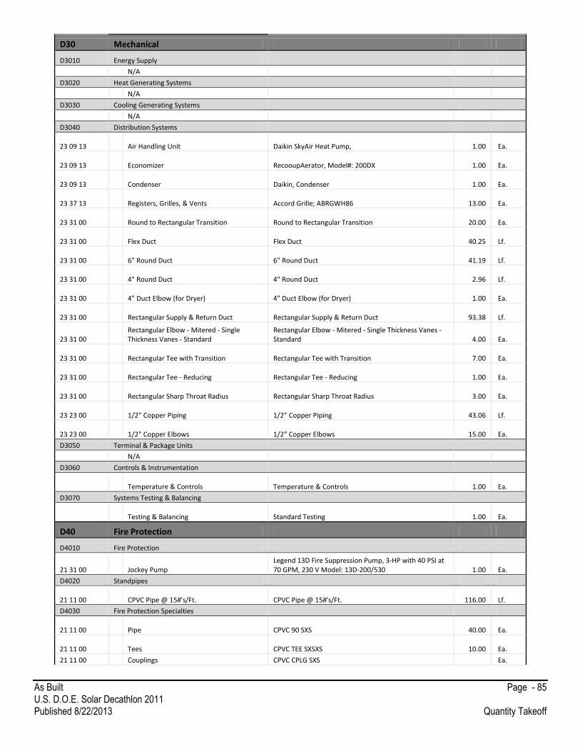
As Built Page - 85 U.S. D.O.E. Solar Decathlon 2011 Published 8/22/2013 Quantity Takeoff
D30 Mechanical
D3010 Energy Supply
N/A
D3020 Heat Generating Systems
N/A
D3030 Cooling Generating Systems
N/A
D3040 Distribution Systems
23 09 13 Air Handling Unit Daikin SkyAir Heat Pump,
1.00 Ea.
23 09 13 Economizer RecooupAerator, Model#: 200DX
1.00 Ea.
23 09 13 Condenser Daikin, Condenser
1.00 Ea.
23 37 13 Registers, Grilles, & Vents Accord Grille; ABRGWH86
13.00 Ea.
23 31 00 Round to Rectangular Transition Round to Rectangular Transition
20.00 Ea.
23 31 00 Flex Duct Flex Duct
40.25 Lf.
23 31 00 6" Round Duct 6" Round Duct
41.19 Lf.
23 31 00 4" Round Duct 4" Round Duct
2.96 Lf.
23 31 00 4" Duct Elbow (for Dryer) 4" Duct Elbow (for Dryer)
1.00 Ea.
23 31 00 Rectangular Supply & Return Duct Rectangular Supply & Return Duct
93.38 Lf.
23 31 00 Rectangular Elbow - Mitered - Single Thickness Vanes - Standard
Rectangular Elbow - Mitered - Single Thickness Vanes - Standard
4.00 Ea.
23 31 00 Rectangular Tee with Transition Rectangular Tee with Transition
7.00 Ea.
23 31 00 Rectangular Tee - Reducing Rectangular Tee - Reducing
1.00 Ea.
23 31 00 Rectangular Sharp Throat Radius Rectangular Sharp Throat Radius
3.00 Ea.
23 23 00 1/2" Copper Piping 1/2" Copper Piping
43.06 Lf.
23 23 00 1/2" Copper Elbows 1/2" Copper Elbows
15.00 Ea.
D3050 Terminal & Package Units
N/A
D3060 Controls & Instrumentation
Temperature & Controls Temperature & Controls
1.00 Ea.
D3070 Systems Testing & Balancing
Testing & Balancing Standard Testing
1.00 Ea.
D40 Fire Protection
D4010 Fire Protection
21 31 00 Jockey Pump Legend 13D Fire Suppression Pump, 3-HP with 40 PSI at 70 GPM, 230 V Model: 13D-200/530
1.00 Ea.
D4020 Standpipes
21 11 00 CPVC Pipe @ 15#'s/Ft. CPVC Pipe @ 15#'s/Ft.
116.00 Lf.
D4030 Fire Protection Specialties
21 11 00 Pipe CPVC 90 SXS
40.00 Ea.
21 11 00 Tees CPVC TEE SXSXS
10.00 Ea.
21 11 00 Couplings CPVC CPLG SXS Ea.
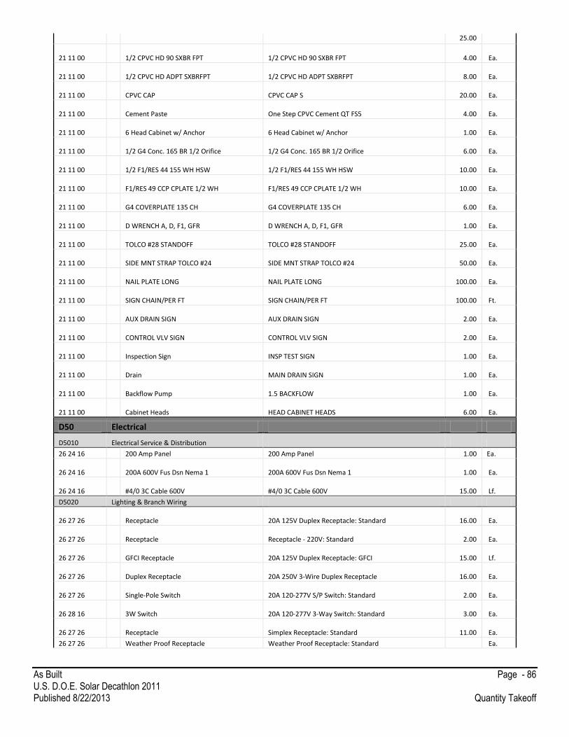
As Built Page - 86 U.S. D.O.E. Solar Decathlon 2011 Published 8/22/2013 Quantity Takeoff
25.00
21 11 00 1/2 CPVC HD 90 SXBR FPT 1/2 CPVC HD 90 SXBR FPT
4.00 Ea.
21 11 00 1/2 CPVC HD ADPT SXBRFPT 1/2 CPVC HD ADPT SXBRFPT
8.00 Ea.
21 11 00 CPVC CAP CPVC CAP S
20.00 Ea.
21 11 00 Cement Paste One Step CPVC Cement QT FS5
4.00 Ea.
21 11 00 6 Head Cabinet w/ Anchor 6 Head Cabinet w/ Anchor
1.00 Ea.
21 11 00 1/2 G4 Conc. 165 BR 1/2 Orifice 1/2 G4 Conc. 165 BR 1/2 Orifice
6.00 Ea.
21 11 00 1/2 F1/RES 44 155 WH HSW 1/2 F1/RES 44 155 WH HSW
10.00 Ea.
21 11 00 F1/RES 49 CCP CPLATE 1/2 WH F1/RES 49 CCP CPLATE 1/2 WH
10.00 Ea.
21 11 00 G4 COVERPLATE 135 CH G4 COVERPLATE 135 CH
6.00 Ea.
21 11 00 D WRENCH A, D, F1, GFR D WRENCH A, D, F1, GFR
1.00 Ea.
21 11 00 TOLCO #28 STANDOFF TOLCO #28 STANDOFF
25.00 Ea.
21 11 00 SIDE MNT STRAP TOLCO #24 SIDE MNT STRAP TOLCO #24
50.00 Ea.
21 11 00 NAIL PLATE LONG NAIL PLATE LONG
100.00 Ea.
21 11 00 SIGN CHAIN/PER FT SIGN CHAIN/PER FT
100.00 Ft.
21 11 00 AUX DRAIN SIGN AUX DRAIN SIGN
2.00 Ea.
21 11 00 CONTROL VLV SIGN CONTROL VLV SIGN
2.00 Ea.
21 11 00 Inspection Sign INSP TEST SIGN
1.00 Ea.
21 11 00 Drain MAIN DRAIN SIGN
1.00 Ea.
21 11 00 Backflow Pump 1.5 BACKFLOW
1.00 Ea.
21 11 00 Cabinet Heads HEAD CABINET HEADS
6.00 Ea.
D50 Electrical
D5010 Electrical Service & Distribution
26 24 16 200 Amp Panel 200 Amp Panel 1.00 Ea.
26 24 16 200A 600V Fus Dsn Nema 1 200A 600V Fus Dsn Nema 1
1.00 Ea.
26 24 16 #4/0 3C Cable 600V #4/0 3C Cable 600V
15.00 Lf.
D5020 Lighting & Branch Wiring
26 27 26 Receptacle 20A 125V Duplex Receptacle: Standard
16.00 Ea.
26 27 26 Receptacle Receptacle - 220V: Standard
2.00 Ea.
26 27 26 GFCI Receptacle 20A 125V Duplex Receptacle: GFCI
15.00 Lf.
26 27 26 Duplex Receptacle 20A 250V 3-Wire Duplex Receptacle
16.00 Ea.
26 27 26 Single-Pole Switch 20A 120-277V S/P Switch: Standard
2.00 Ea.
26 28 16 3W Switch 20A 120-277V 3-Way Switch: Standard
3.00 Ea.
26 27 26 Receptacle Simplex Receptacle: Standard
11.00 Ea.
26 27 26 Weather Proof Receptacle Weather Proof Receptacle: Standard Ea.

As Built Page - 87 U.S. D.O.E. Solar Decathlon 2011 Published 8/22/2013 Quantity Takeoff
2.00
26 05 33 Junction Box Junction Boxes
46.00 Ea.
26 05 00 Cable #14/2C Nm-B Romex Wire
500.00 Lf.
26 05 00 Cable #8/3C Nm-B Romex Wire
200.00 Lf.
26 51 00 Track Head Lighting Kit.- Lowe's, Portfolio Silver Step Linter Track, Model#: 14565-001
20.00 Ea.
26 51 00 Track Pendant Lighting Kit.- Kichler Lighting, Hendrick-Mini Pendant, Model#: 3475N1
4.00 Ea.
26 51 00 Under cabinet Lighting Kit.- Kichler Lighting, Modular LED Puck Light, Model#: 12310BK
- Ea.
26 51 00 Ceiling Fan Lighting Bed- Kichler Lighting, Eva 46" Fan, Model#: 300121SBK
2.00 Ea.
26 51 00 Ceiling Mounted Lighting Closet- Lowe's, Sea Gull Lighting, Model#: 49180BLE-98
6.00 Ea.
26 51 00 Wall Mounted Vanity Lighting Bath- Kichler Lighting, Tubes, Model#: 5968NI
1.00 Ea.
26 51 00 Ceiling Mounted Bath- Lowe's, Portfolio 3-Light, Model#: 17787-000
1.00 Ea.
23 05 13 3Ph Motor- #8/3C + Grd NEMA MG 1, Design B, medium induction motor
1.00 Ea.
Misc. Mech. Connections & Wire Misc. Mech. Connections & Wire
1.00 Ea.
D5030 Communications & Security Systems
26 29 13 Data/Com N/A
1.00 Ea.
D5090 Other Electrical Systems
28 31 11 Fire Alarm Kidde FireX 120V AC Wire-IN Smoke Alarm, Model I5000
1.00 Ea.
E10 Equipment
E1010 Commercial Equipment
11 31 13 Cooktop GE Profile 36" Electric Induction Cooktop, PHP960SM
1.00 Ea.
11 31 13 Refrigerator
GE Profile Energy Star 25.9 Cu. Ft. Side-by-Side Stainless Steel Refrigerator with Dispenser and Turbo Cool Setting, PSHS6PGZSS
1.00 Ea.
11 31 13 Dishwasher GE Profile Stainless Interior Built-In Dishwasher w/ Hidden Controls, Model#: PDWT180VSS
1.00 Ea.
11 31 13 Microwave
GE Profile Advantium Wall Oven, Stainless Steel with black glass, Glass touch controls, 1.7 Cu. Ft. capacity, PSB2201NSS
1.00 Ea.
11 31 13 Oven GE Profile 30" Built-in Single Convention Wall Oven, 4.4 Cu. Ft., Stainless Steel with Black Glass, PT916SRSS
1.00 Ea.
11 31 13 Garbage Disposal GE 3/8-HP Garbage Disposal with Sound Insulation, Jam Resistant, GFC320V
1.00 Ea.
11 31 13 Storage Drawer GE Profile Wall Oven Storage Drawer, JX2201NSS
1.00 Ea.
11 31 13 Downdraft System GE Profile 36" Telescopic Downdraft System, PVB98STSS
1.00 Ea.
11 31 13 Washing Machine GE Energy Star 4.1 DOE Cu. Ft. Stainless Steel Capacity Frontload Washer, Model#: GFWH1400D
1.00 Ea.
11 31 13 Dryer GE 7.0 Cu. Ft. capacity Frontload Electric Dryer with Steam, Model#: GFDS140ED
1.00 Ea.
E1020 Institutional Equipment N/A

As Built Page - 88 U.S. D.O.E. Solar Decathlon 2011 Published 8/22/2013 Quantity Takeoff
E1030 Vehicular Equipment N/A
E1090 Other Equipment
N/A
F10 Special Construction
F1010 Special Structures
03 40 00 Deck Footings Deck Footings 43.00 Ea.
06 43 13 Exterior Decking 1x6 Trex Decking, 2x4 Joists @ 16" O.C., Maximum Span- 50". 1054.95 Sq. Ft.
F1020 Integrated Construction
N/A
F1030 Special Construction Systems
48 19 16 Photovoltaic Rack Unirack, Sun Fame, Slot Rail, Cap Strip, Cap Strip Screws, End Caps, Splices 410.83 Sq. Ft.
F1040 Special Facilities
N/A
G20 Site Improvement
G2010 Roadways
N/A
G2020 Parking Lots
N/A
G2030 Pedestrian Paving
N/A
G2040 Site Development
05 52 13 Half Fence w/ EMT Railing
Custom Hardwoods, LLC. Beech Hard Wood Style No: 1340, w/ 1" Aluminum 6063-T6 conduit from Hollaender Manufacturing Co. Item No.: 96121
199.66 Lf.
05 52 13 Green Wall w/EMT Railing
Custom Hardwoods, LLC. Beech Hard Wood Style No: 1340, w/ 1" Aluminum 6063-T6 conduit from Hollaender Manufacturing Co. Item No.: 96121
36.00 Lf.
06 10 00 Hand Rails
101.00 Lf.
32 94 33 Planter Boxes with Wood Siding 2x4 and 1x6 Pressure Treated Dimensional Lumber, 1/2" Grade C Plywood Sheathing
639.26 Sq. Ft.
32 71 00 Digester Digester
1.00 Ea.
G2050 Landscaping
32 93 00 Landscaping Trees Western Redbud 3.00 Ea.
32 93 00 Landscaping Large Plants Wild Grape Rogers Red 26.00 Ea.
32 93 00 Landscaping Medium Plants Dune Lupine 24.00 Ea.
32 93 00 Landscaping Small Plants Bladderpod 133.00 Ea.
32 93 00 Landscaping Irrigation System Landscape Irrigation System 1.00 Ea.
G40 Site Electrical Utilities
G4010 Electrical Distribution
48 19 16 Photovoltaic Panels Sanyo HIT Power 220A 34.00 Ea.
48 19 16 Photovoltaic Inverters
Enphase M210, DC to AC transformer for an individual photovoltaic model. One microinverter per photovoltaic module. 17.00 Ea.
48 19 16 150A Service Cable 150A Service Cable 10.00 Lf.
48 19 16 3/4" PVC 3/4" PVC 200.00 Lf.
48 19 16 2" PVC 2" PVC 20.00 Lf.
48 19 16 #12 Wire #12 Wire 700.00 Lf.
48 19 16 4x4x4" Box-Nema 1 4x4x4" Box-Nema 1 3.00 Ea.
48 19 16 Weather Head Weather Head 1.00 Ea.

As Built Page - 89 U.S. D.O.E. Solar Decathlon 2011 Published 8/22/2013 Quantity Takeoff
G4020 Site Lighting
26 56 00 Exterior Site Lighting- Path Lighting Cooper Plane Step Light 21.00 Ea.
26 56 00 Exterior Site Lighting- Overhead Lighting Cooper ENV Entri LED Round Reveals 10.00 Ea.
G4030 Site Communications and Security
N/A
G4090 Other Electrical Utilities
N/A

As Built Page - 90 U.S. D.O.E. Solar Decathlon 2011 Published 8/22/2013 Construction Specifications
Construction Specifications Division 01 - General Requirements
01 51 13 Temporary Electricity
01 54 19 Temporary Crane
Division 03 – Concrete
03 40 00 Precast Concrete
Division 05 – Metals
05 12 00 Structural Steel Framing
Division 06 – Wood, Plastics, and Composites
06 10 00 Rough Carpentry
06 12 00 Structural Insulated Panels
06 15 33 Wood Decking
06 16 53 Moisture Resistant Sheathing Board
06 17 53 Shop-Fabricated Wood Trusses
06 40 23 Interior Architectural Woodwork
06 41 00 Custom Casework
06 41 93 Cabinet and Drawer Hardware
Division 07 – Thermal and Moisture Protection
07 14 16 Cold Fluid-Applied Waterproofing
07 21 16 Blanket Insulation
07 21 19 Foamed-In-Place Insulation
07 25 00 Weather Barrier
07 26 13 Vapor Retarder
07 41 13 Metal Roof Panels
07 44 56 Fiber Reinforced Cementitous Panels
07 45 23 Wood Siding
07 53 23 EPDM
07 71 23 Gutters and Downspouts
07 90 05 Joint Sealants
07 91 16 Joint Gaskets
07 92 12 Elastomeric Joint Sealants
Division 08 – Openings
08 10 00 Doors and Frames
08 54 13 Fiberglass Windows
Division 09 – Finishes
09 29 00 Gypsum Board
09 30 00 Tiling
09 64 29 Wood Base and Wood Flooring
Division 10 – Specialties
10 28 16.13 Residential Bath Accessories
Division 11 – Equipment
11 30 00 Electronics Residential
11 31 13 Residential Kitchen Appliances
11 31 23 Residential Laundry Appliances

As Built Page - 91 U.S. D.O.E. Solar Decathlon 2011 Published 8/22/2013 Construction Specifications
Division 12 – Furnishings
12 20 00 Window Treatment
12 58 00 Residential Furniture
Division 21 – Fire Suppression
21 05 00 Common Work Results for Fire Suppression
21 05 33 Heat Tracing for Fire Suppression Piping
21 10 00 Water-Based Fire-Suppression Systems
Division 22 – Plumbing
22 05 00 Common Work Results for Plumbing
22 05 48 Vibration and Seismic Controls for Plumbing Piping and Equipment
22 07 00 Plumbing Insulation
22 11 16 Domestic Water Piping
22 11 19 Domestic Water Piping Specialties
22 11 23 Domestic Water Pumps
22 12 19 Facility Ground-Mounted, Potable-Water Storage Tanks
22 13 16 Sanitary Waste and Vent Piping
22 33 00 Electric Domestic Water Heaters
22 41 00 Residential Plumbing Fixtures
22 41 23 Residential Shower Receptors and Basins
Division 23 – Heating, Ventilating, and Air-Conditioning (HVAC)
23 05 00 Common Work Results for HVAC
23 05 13 Common Motor Requirements for HVAC Equipment
23 05 23 General-Duty Valves for HVAC Piping
23 05 93 Testing, Adjusting, and Balancing for HVAC
23 07 00 HVAC Insulation
23 09 13 Instrumentation and Control for HVAC
23 23 00 Refrigerant Piping
23 31 00 HVAC Ducts and Casings
23 37 13 Diffusers, Registers, and Grilles
23 62 00 Packaged Compressor and Condenser Units
23 78 50 Air-to-Air Energy Recovery Ventilators
Division 26 – Electrical
26 05 00 Common Work Results for Electrical
26 05 33 Raceway & Junction Box for Electrical Systems
26 09 23 Lighting Control Devices
26 22 00 Low Voltage Transformers
26 24 16 Panelboard
26 27 13 Electricity Metering
26 27 26 Wiring Devices
26 28 13 Fuses
26 28 16 Enclosed Switches and Circuit Breakers
26 29 13 Enclosed Controllers
26 31 00 Photovoltaic Collectors
26 41 13 Lightning Protection for Structures
26 43 13 Surge Protection Devices
26 50 00 Interior Lighting

As Built Page - 92 U.S. D.O.E. Solar Decathlon 2011 Published 8/22/2013 Construction Specifications
26 56 00 Exterior Lighting
Division 28 – Electronic Safety and Security
28 31 11 Digital, Addressable Fire-Alarm System
26 31 11 Smoke & Carbon Monoxide Alarm System
Division 32 – Exterior Improvements
32 71 00 Constructed Wetlands
32 93 00 Plants
Division 48 – Electrical Power Generation
48 19 16 Electrical Power Generation Inverters
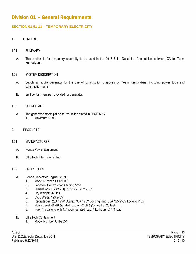
As Built Page - 93 U.S. D.O.E. Solar Decathlon 2011 TEMPORARY ELECTRICITY Published 8/22/2013 01 51 13
Division 01 – General Requirements
SECTION 01 51 13 – TEMPORARY ELECTRICITY
1. GENERAL
1.01 SUMMARY
A. This section is for temporary electricity to be used in the 2013 Solar Decathlon Competition in Irvine, CA for Team Kentuckiana.
1.02 SYSTEM DESCRIPTION
A. Supply a mobile generator for the use of construction purposes by Team Kentuckiana, including power tools and construction lights.
B. Spill containment pan provided for generator.
1.03 SUBMITTALS
A. The generator meets psf noise regulation stated in 36CFR2.12 1. Maximum 60 dB
2. PRODUCTS
1.01 MANUFACTURER
A. Honda Power Equipment
B. UltraTech International, Inc..
1.02 PROPERTIES
A. Honda Generator Engine GX390 1. Model Number: EU6500IS 2. Location: Construction Staging Area 3. Dimensions [L x W x H]: 33.5” x 26.4” x 27.5” 4. Dry Weight: 260 lbs. 5. 6500 Watts, 120/240V 6. Receptacles: 20A 125V Duplex, 30A 125V Locking Plug, 30A 125/250V Locking Plug 7. Noise Level: 60 dB @ rated load or 52 dB @1/4 load at 25 feet 8. Fuel: 4.5 gallons with 4.7 hours @rated load, 14.0 hours @ 1/4 load
B. UltraTech Containment 1. Model Number: UTI-2351

As Built Page - 94 U.S. D.O.E. Solar Decathlon 2011 TEMPORARY ELECTRICITY Published 8/22/2013 01 51 13
2. Dimensions: [LxWxH]: 54”x29-3/4”x3-1/2” 3. Weight: 102 lbs 4. Containment Capacity: 75 gallons
END OF SECTION 01 51 13
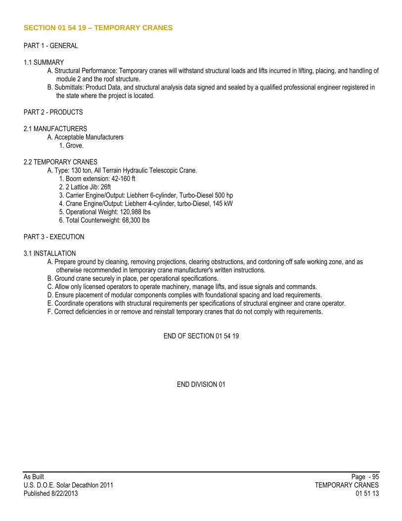
As Built Page - 95 U.S. D.O.E. Solar Decathlon 2011 TEMPORARY CRANES Published 8/22/2013 01 51 13
SECTION 01 54 19 – TEMPORARY CRANES
PART 1 - GENERAL 1.1 SUMMARY
A. Structural Performance: Temporary cranes will withstand structural loads and lifts incurred in lifting, placing, and handling of module 2 and the roof structure.
B. Submittals: Product Data, and structural analysis data signed and sealed by a qualified professional engineer registered in the state where the project is located.
PART 2 - PRODUCTS 2.1 MANUFACTURERS
A. Acceptable Manufacturers 1. Grove.
2.2 TEMPORARY CRANES
A. Type: 130 ton, All Terrain Hydraulic Telescopic Crane. 1. Boom extension: 42-160 ft 2. 2 Lattice Jib: 26ft 3. Carrier Engine/Output: Liebherr 6-cylinder, Turbo-Diesel 500 hp 4. Crane Engine/Output: Liebherr 4-cylinder, turbo-Diesel, 145 kW 5. Operational Weight: 120,988 lbs 6. Total Counterweight: 68,300 lbs
PART 3 - EXECUTION 3.1 INSTALLATION
A. Prepare ground by cleaning, removing projections, clearing obstructions, and cordoning off safe working zone, and as otherwise recommended in temporary crane manufacturer's written instructions.
B. Ground crane securely in place, per operational specifications. C. Allow only licensed operators to operate machinery, manage lifts, and issue signals and commands. D. Ensure placement of modular components complies with foundational spacing and load requirements. E. Coordinate operations with structural requirements per specifications of structural engineer and crane operator. F. Correct deficiencies in or remove and reinstall temporary cranes that do not comply with requirements.
END OF SECTION 01 54 19
END DIVISION 01
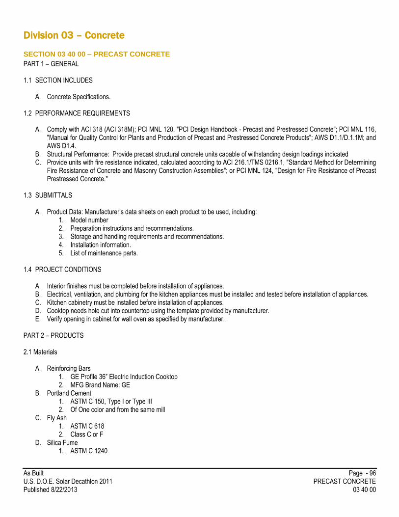
As Built Page - 96 U.S. D.O.E. Solar Decathlon 2011 PRECAST CONCRETE Published 8/22/2013 03 40 00
Division 03 – Concrete
SECTION 03 40 00 – PRECAST CONCRETE
PART 1 – GENERAL 1.1 SECTION INCLUDES
A. Concrete Specifications. 1.2 PERFORMANCE REQUIREMENTS
A. Comply with ACI 318 (ACI 318M); PCI MNL 120, "PCI Design Handbook - Precast and Prestressed Concrete"; PCI MNL 116, "Manual for Quality Control for Plants and Production of Precast and Prestressed Concrete Products"; AWS D1.1/D.1.1M; and AWS D1.4.
B. Structural Performance: Provide precast structural concrete units capable of withstanding design loadings indicated C. Provide units with fire resistance indicated, calculated according to ACI 216.1/TMS 0216.1, "Standard Method for Determining
Fire Resistance of Concrete and Masonry Construction Assemblies"; or PCI MNL 124, "Design for Fire Resistance of Precast Prestressed Concrete."
1.3 SUBMITTALS
A. Product Data: Manufacturer’s data sheets on each product to be used, including:
1. Model number 2. Preparation instructions and recommendations. 3. Storage and handling requirements and recommendations. 4. Installation information. 5. List of maintenance parts.
1.4 PROJECT CONDITIONS
A. Interior finishes must be completed before installation of appliances. B. Electrical, ventilation, and plumbing for the kitchen appliances must be installed and tested before installation of appliances. C. Kitchen cabinetry must be installed before installation of appliances. D. Cooktop needs hole cut into countertop using the template provided by manufacturer. E. Verify opening in cabinet for wall oven as specified by manufacturer.
PART 2 – PRODUCTS 2.1 Materials
A. Reinforcing Bars 1. GE Profile 36” Electric Induction Cooktop 2. MFG Brand Name: GE
B. Portland Cement 1. ASTM C 150, Type I or Type III 2. Of One color and from the same mill
C. Fly Ash 1. ASTM C 618 2. Class C or F
D. Silica Fume 1. ASTM C 1240
As Built Page - 97 U.S. D.O.E. Solar Decathlon 2011 PRECAST CONCRETE Published 8/22/2013 03 40 00
2. Amorphous silica E. Ground Granulated Blast Furnace Slag
1. ASTM C 989 2. Grade 100 or 120
F. Normal-Weight Aggregates 1. ASTM C 33 2. With coarse aggregates complying with class 4S 3. Except as modified by PCI MNL 117
G. Air-Entraining Admixture 1. ASTM C 260
H. Coloring Admixture 1. ASTM C 979
I. Chemical Admixtures 1. ASTM C 494/ C 494M 2. Do not use admixtures containing chlorides.
2.2 ACCESSORIES AND FINISHES
A. Steel Shapes and Plates 1. ASTM A 36/A 36M
B. Carbon-Steel Bolts and Studs 1. ASTM A 307, Grade A (ASTM F 568M, Property Class 4.6) 2. carbon-steel, hex-head bolts and studs; carbon-steel nuts, ASTM A 563 (ASTM A 563M) 3. flat, unhardened steel washers, ASTM F 844
C. Zinc-Coated Finish 1. For exterior steel items, steel in exterior walls, and items indicated for galvanizing, apply zinc coating by hot-dip
process according to ASTM A 123/A 123M or ASTM A 153/A 153M 2.3 CONCRETE MIX
A. Proportion normal-weight concrete mixes to provide the following properties
1. Compressive Strength: 5000 psi (27.6 MPa) at 28 days. 2. Water-Cementitious Materials Ratio: 0.45 maximum. 3. Air Content: 5.5 to 7.5 percent for concrete exposed to freezing and thawing, 4. Use fly ash, pozzolan, ground granulated blast-furnace slag, and silica fume as needed to reduce the total amount of
portland cement, which would otherwise be used, by not less than 40 percent. 5. Limit use of fly ash to 25 percent replacement of portland cement by weight and granulated blast-furnace slag to 40
percent of portland cement by weight; metakaolin and silica fume to 10 percent of portland cement by weight.
B. Concrete Mixing 1. Comply with ASTM C 94
2.4 PRECAST UNITS
A. Fabricate precast concrete units straight and true to size and shape with exposed edges and corners precise and true so each finished panel complies with PCI MNL 117 product tolerances as well as position tolerances for cast-in items
B. Panel faces shall be free of joint marks, grain, and other obvious defects. Corners, including false joints shall be uniform, straight, and sharp Air Content: 5.5 to 7.5 percent for concrete exposed to freezing and thawing,
C. Finishes: Standard for formed surfaces. Trowel unformed surfaces D. Replace precast concrete units deficient in strength, manufacturing tolerances, and finishes.

As Built Page - 98 U.S. D.O.E. Solar Decathlon 2011 PRECAST CONCRETE Published 8/22/2013 03 40 00
PART 3 – EXECUTION 3.1 INSTALLATION
A. Install clips, hangers, bearing pads, and other accessories required for connecting precast concrete units to supporting
members and backup materials
B. Install bearing pads level, true, and on uniform bearing surfaces
C. Protect precast units and bearing pads from damage during welding..
D. Install precast units level, plumb, square, true, and in alignment within the recommended erection tolerances of PCI MNL 135.
E. Connect precast concrete units in position by bolting, welding, grouting, or as otherwise indicated on Shop Drawings. F. Welding: Comply with applicable AWS D1.1/D1.1M and AWS D1.4 for welding, welding electrodes, appearance, quality of
welds, and methods used in correcting welding work G. Shore and brace precast concrete units to maintain location, stability, and alignment until permanent connections are installed H. Grout open spaces at keyways, connections, and joints after precast concrete units have been placed and secured I. Clean exposed surfaces of precast concrete units after erection and completion of joint treatment to remove weld marks, other
markings, dirt, and stains
END OF SECTION 03 40 00
END DIVISION 03

As Built Page - 99 U.S. D.O.E. Solar Decathlon 2011 PIPE AND TUBE RAILINGS Published 8/22/2013 05 22 13
Division 05 – Metals
SECTION 05 12 00 – STRUCTURAL STEEL FRAMING
PART 1 – GENERAL 1.1 SECTION INCLUDES
A. Structural Steel 1.2 PERFORMANCE REQUIREMENTS
A. Connections: Provide details of connections required by the Contract Documents to be selected or completed by structural-steel fabricator
a. Use LRFD; data are given at factored-load level. B. Comply with applicable provisions of the following:
a. AISC 303 b. AISC 341 and AISC 341S1 c. AISC 360 d. RCSC’s “Specification for Structural Joints Using ASTM A 325 or A 490 Bolts
PART 2 – PRODUCTS 2.1 STRUCTURAL STEEL
A. Recycled Content of Steel Products: 1. Postconsumer recycled content plus one-half of preconsumer recycled content not less than 50 percent
B. W-Shapes: 1. ASTM A 992/A 992M
C. Channels, Angles: 1. ASTM A 36/A 36M
D. Plate and Bar: 1. ASTM A 36/A 36M
E. Cold-Formed Hollow Structural Sections: 1. ASTM A 500, 2. Grade B, 3. structural tubing
2.2 ACCESSORIES
A. Anchor Rods: ASTM F 1554, Grade 36 1. Configuration: Straight 2. Nuts: ASTM A 563 hex carbon steel 3. Plate Washers: ASTM A 36/A 36M carbon steel 4. Washers: ASTM F 436, Type 1 hardened carbon steel
PART 3 – EXECUTION 3.1 FABRICATION
A. Structural Steel: Fabricate and assemble in shop to greatest extent possible. Fabricate according to AISC's "Code of
Standard Practice for Steel Buildings and Bridges" and AISC 360.

As Built Page - 100 U.S. D.O.E. Solar Decathlon 2011 PIPE AND TUBE RAILINGS Published 8/22/2013 05 22 13
B. Weld Connections: Comply with AWS D1.1/D1.1M for tolerances, appearances, welding procedure specifications, weld
quality, and methods used in correcting welding work
3.2 ERECTION
A. Set structural steel accurately in locations and to elevations indicated and according to AISC 303 and AISC 360.
B. Base Bearing and Leveling Plates: Clean concrete- and masonry-bearing surfaces of bond-reducing materials, and roughen
surfaces prior to setting plates. Clean bottom surface of plates
1. Set plates for structural members on wedges, shims, or setting nuts as required
2. Weld plate washers to top of base plate
3. Snug-tighten anchor rods after supported members have been positioned and plumbed. Do not remove wedges or
shims but, if protruding, cut off flush with edge of plate before packing with grout
4. Promptly pack grout solidly between bearing surfaces and plates so no voids remain. Neatly finish exposed
surfaces; protect grout and allow to cure
C. Align and adjust various members forming part of complete frame or structure before permanently fastening. Before
assembly, clean bearing surfaces and other surfaces that will be in permanent contact with members. Perform necessary
adjustments to compensate for discrepancies in elevations and alignment
D. Do not use thermal cutting during erection unless approved by Engineer. Finish thermally cut sections within smoothness
limits in AWS D1.1/D1.1M
E. Weld Connections: Comply with AWS D1.1/D1.1M for tolerances, appearances, welding procedure specifications, weld
quality, and methods used in correcting welding work
END OF SECTION 05 12 00
END DIVISION 05

As Built Page - 101 U.S. D.O.E. Solar Decathlon 2011 ROUGH CARPENTRY Published 8/22/2013 06 10 00
Division 06 – Woods, Plastics, and Composites
SECTION 06 10 00 – ROUGH CARPENTRY
PART 1 – GENERAL 1.1 SECTION INCLUDES
A. Framing with dimension lumber. B. Framing with engineered wood products. C. Wood blocking and nailers. D. Plywood backing panels. E. Wood sheathing
1.2 DEFINITIONS
A. Exposed Framing: Framing not concealed by other construction. B. Dimension Lumber: Lumber of 2 inches nominal (38 mm actual) or greater but less than 5 inches nominal (114 mm actual) in
least dimension. 1.3 DELIVERY, STORAGE, AND HANDLING
A. Stack lumber flat with spacers beneath and between each bundle to provide circulation. Protect lumber from weather by
covering with waterproof sheeting, securely anchored. Provide for air circulation around stacks and under coverings. PART 2 – PRODUCTS 2.1 WOOD PRODUCTS, GENERAL
A. Lumber: DOC PS 20 and applicable rules of grading agencies indicated. If no grading agency is indicated, provide lumber that complies with applicable rules of any rules-writing agency certified by the ALSC Board of Review. Provide lumber graded by an agency certified by the ALSC Board of Review to inspect and grade lumber under the rules indicated.
1. Factory mark each piece of lumber with grade stamp of grading agency. 2. Where nominal sizes are indicated, provide actual sizes required by DOC PS 20 for moisture content specified.
Where actual sizes are indicated, they are minimum dressed sizes for dry lumber. 3. Provide dressed lumber, S4S, unless otherwise indicated. 4. Maximum Moisture Content of Lumber: 15 percent.
B. Engineered Wood Products: Provide engineered wood products acceptable to authorities having jurisdiction and for which
current model code research or evaluation reports exist that show compliance with building code in effect for Project. 2.2 WOOD-PRESERVATIVE-TREATED LUMBER
A. Preservative Treatment by Pressure Process: AWPA U1; Use Category UC3b for exterior construction not in contact with the ground.
B. Kiln-dry lumber after treatment to a maximum moisture content of 19 percent. Do not use material that is warped or that does not comply with requirements for untreated material.
C. Mark lumber with treatment quality mark of an inspection agency approved by the ALSC Board of Review. D. Application: Treat items indicated on Drawings and the following:
1. Wood cants, nailers, curbs, equipment support bases, blocking, stripping, and similar members in connection with roofing, flashing, vapor barriers, and waterproofing.

As Built Page - 102 U.S. D.O.E. Solar Decathlon 2011 ROUGH CARPENTRY Published 8/22/2013 06 10 00
2. Wood sills, sleepers, blocking, and similar concealed members in contact with masonry or concrete. 3. Wood framing and furring attached to the interior of below-grade exterior masonry or concrete walls. 4. Wood framing members that are less than 6 inches above the ground in crawlspaces or unexcavated areas. 5. Wood floor plates that are installed on steel framing.
2.3 DIMENSION LUMBER FRAMING
A. Non-Load-Bearing Interior Partitions: Standard, Stud or No. 3 grade. 1. Species:
i. Spruce-pine-fir; NLGA. B. Load-Bearing Partitions: No. 2.
1. Species: i. Southern Pine.
C. Ceiling Joists: Construction or No. 2 grade. 1. Species:
i. Southern Pine. D. Trellis
1. Provide heat treated materials (“cooked wood”) treated as follows: heated wood up to 250c, using a water vapor as shielded gas.
2. Trellis Infill and Framing Structure i. 2x6s for all members ii. Western Red Cedar, WWPA, No. 2 Grade
2.5 ENGINEERED WOOD PRODUCTS
A. Engineered Wood Products, General: Products shall contain no urea formaldehyde. B. Sheathing:
1. Advantex Decking i. ¾” floor decking structural sheathing or equivalent
2. OSB Structure 1 i. APA
2.6 MISCELLANEOUS LUMBER
A. General: Provide miscellaneous lumber indicated and lumber for support or attachment of other construction, including the following:
1. Blocking. 2. Nailers. 3. Furring.
B. For items of dimension lumber size, provide Standard, Stud or No. 3 grade lumber of any species. C. For blocking not used for attachment of other construction, Utility, Stud or No. 3 grade lumber of any species may be used
provided that it is cut and selected to eliminate defects that will interfere with its attachment and purpose. D. For furring strips for installing plywood or hardboard paneling, select boards with no knots capable of producing bent-over
nails and damage to paneling. 2.7 PLYWOOD BACKING PANELS
A. Equipment Backing Panels: DOC PS 1, Exposure, C-D Plugged, fire-retardant treated, in thickness indicated or, if not indicated, not less than ¾-inch nominal thickness.
1. Plywood shall comply with the testing and product requirements of the California Department of Health Services’ “Standard Practice for the Testing of Volatile Organic Emissions from Various Sources Using Small-Scale Environmental Chambers.”
As Built Page - 103 U.S. D.O.E. Solar Decathlon 2011 ROUGH CARPENTRY Published 8/22/2013 06 10 00
2.8 FASTENERS
A. General: Provide fasteners of size and type indicated that comply with requirements specified in this article for material and manufacture.
1. Where rough carpentry is exposed to weather, in ground contact, pressure-preservative, or in area of high relative humidity, provide fasteners with hot-dip zinc coating complying with ASTM A 153/A 153M.
B. Nails, Brads, Staples: ASTM F 1667. C. Power-Driven Fasteners: NES NER-272 D. Wood Screws: ASME B18.6.1. E. Lag Bolts: ASME B18.2.1 (ASME B18.2.3.M). F. Bolts: Steel bolts complying with ASTM A 307, Grade A (ASTM F 568M, Property Class 4.6) with ASTM A 563 (ASTM A
563M) hex nuts and where indicated, flat washers. PART 3 – EXECUTION 3.1 INSTALLATION
A. Set rough carpentry to required levels and lines, with members plumb, true to line, cut and fitted. Fit rough carpentry to other construction; scribe and cope as needed to accurate fit. Locate furring, nailers, blocking and similar supports to comply with requirements for attachments for attaching other construction.
B. Framing Standard: Comply with AF&PA’s ECD 1, “Details for Conventional Wood Frame Construction,” unless otherwise indicated.
C. Framing with Engineered Wood Products: Install engineered wood products to comply with manufacturer’s written instructions. D. Install plywood backing panels by fastening to studs; coordinate locations with utilites requiring backing panels. E. Do not splice structural members between supports unless otherwise indicated. F. Use steel common nails unless otherwise indicated. Select fasteners of size that will not fully penetrate members where
opposite side will be exposed to view or will receive finish materials. Make tight connections between members. Installed fasteners without splitting wood. Drive nails snug but do not countersink nail heads unless otherwise indicated.
G. For exposed work, arrange fasteners in straight rows parallel with edges of members, with fasteners evenly spaced, with adjacent rows staggered and use finish nails unless otherwise indicated by the drawings.
H. 2x6 cross members of trellis will be notched at intersection with 2x10 headers (2” in depth”).
END OF SECTION 06 10 00
As Built Page - 104 U.S. D.O.E. Solar Decathlon 2011 STRUCTURALLY INSULATED PANELS Published 8/22/2013 06 12 00
SECTION 06 12 00 – STRUCTURALLY INSULATED PANELS
PART 1 – GENERAL 1.1 SUMMARY
A. Section Includes: Structural Insulated Panels (SIPs)
B. Related Sections:
1. Section 06 10 00 ROUGH CARPENTRY 2. Section 07 14 16 COLD FLUID-APPLIED WATERPROOFING 3. Section 07 71 23 MANUFACTURERED GUTTERS AND DOWNSPOUTS 4. Section 07 44 56 FIBER REINFORCED CEMENTITOUS PANELS 5. Section 07 91 16 JOINT GASKETS 6. Section 09 29 00 GYPSUM BOARD
1.2 SYSTEM DESCRIPTION
A. Structural Insulated Panels (SIPs) framing system consist of oriented strand board (OSB), structural lumber and polyurethane foam, connectors and fasteners supplied by manufacturer, all as shown on drawings, specified herein, and/or described in manufacturer’s instructions.
1.3 REFERENCES
A. ICC ES AC04 – Acceptance Criteria for Sandwich Panels. B. ICC ES AC04 – Acceptance Criteria for Sandwich Panels Adhesives. C. EPA – Registered products listing
1.4 SUBMITTALS
A. Product Data: Submit product data for specified products. 1. Manufacturers product sheet, evidence of compliance with code requirements, including current test data and listing
report, calculations stamped by an architect or professional engineer. 2. Manufacture to provide complete panel shop drawings, showing all panel sizes, electrical layout, window openings
and any other structural elements. 3. Manufacturer’s Instructions: SIP Manufacturer’s construction detail book and load design charts.
B. Calculations: Provide structural calculations by a registered architect or professional engineer licensed in the state of Indiana or Kentucky, qualified to perform such work.
C. Quality Assurance Submittals: 1. Certificate: Product certificate showing compliance to Third party Quality Control Program
D. Warranty: Warranty documents specified herein. 1.5 QUALITY ASSURANCE
A. Installer Qualifications: Installer should be experience in performing work of this section and should have specialized in installation of work similar to that required for this project.
B. Source Limitations: All accessories to be as furnished or recommended by SIP manufacturer. 1.6 REGULATORY REQUIREMENTS
A. SIPs shall be recognized for compliance with International Building Code and International Residential Code in a current third party report.

As Built Page - 105 U.S. D.O.E. Solar Decathlon 2011 STRUCTURALLY INSULATED PANELS Published 8/22/2013 06 12 00
1.7 DELIVERY, STORAGE, & HANDLING
A. Ordering: Comply with SIP manufacturer’s ordering instructions and lead-time requirements to avoid construction delays. B. Delivery: Deliver materials from SIP manufacturer with identification labels or markings intact. C. Off-load SIPs from SIPs from truck and handling using forklift or other means to prevent damage to SIPs. D. SIPs shall be fully supported in storage and prevented from contact with the ground. E. SIPs shall be protected from weather. Protect against exposure to rain, water, dirt, mud and other residue that may affect SIP
performance. Cover stored SIPs with breathable protective wraps. SIPs shall be stored in a protected area. 1.8 WARRANTY
A. Project Warranty: Refer to Conditions of the Contract for project warranty provisions. B. Manufacturer’s Warranty: Lifetime warranty on defects in materials and workmanship.
PART 2 – PRODUCTS 2.1 MANUFACTURERS:
A. Thermocore Panel System, 1801 Hancel Parkway, Mooresville, IN 46158 2.2 MATERIALS:
A. SIPs consisting of the following: 1. 4-12” (Walls) and 8-1/4” (Roof) foam core panels with 7/16” OSB/OSB (interior/exterior) skins. Each panel has a
foam core of class 1/A polyurethane foam at a minimum density of 2.2 lbs. 2. OSB identified with APA or PFS performance mark with Exposure I durability rating and performance in accordance
with DOC PS-2 span rating 24/16 or greater. 3. All panels are manufactured to a thickness tolerance of +/- 3/32” 4. All lumber used in panel manufacturing shall be #2 or better SPF.
2.3 ACCESSORIES
A. Fasteners: corrosion resistant SIP screws compatible with SIP system shall be provided by the SIPs manufacturer. 1. Wood Screws for attachment to wood members.
B. SIP Gasket: Foam gasket shall be provided by the SIP manufacturer. C. Dimensional Lumber: SPF, #2 or better.
2.4 FABRICATION
A. Sizes: SIPs shall be fabricated in accordance with approved Shop Drawings. B. Thermal Resistance, R-value
1. 6-1/2” thick SIP with R-value of 40 2. 8-1/4” thick SIP with R-value of 50
C. Electrical raceways and boxes: TBD
2.5 SOURCE QUALITY
A. Source Quality Assurance: Each SIP component required shall be supplied by SIP manufacturer and shall be obtained from selected SIP manufacturer or its approved supplier.
1. Each SIP shall be labeled indicating Third Party certification. 2. Provide evidence of Third party inspection and labeling of all insulation used in manufacture of SIPs. 3. Dimensional Tolerance – shall comply with values listed in the manufacturer’s Quality Control Manual.
B. Source Quality: Obtain SIPs from a single manufacturer.
As Built Page - 106 U.S. D.O.E. Solar Decathlon 2011 STRUCTURALLY INSULATED PANELS Published 8/22/2013 06 12 00
PART 3 – EXECUTION 3.1 MANUFACTURER’S INSTRUCTIONS
A. Compliance: Comply with manufacturer’s listing report, Load Design Charts, Detail Book, Shop Drawings, and product data for installation.
B. Plans shall be reviewed by a qualified architect/engineer and shall be signed and/or sealed. Deviations from standard detail and load design values shall be calculated and signed and/or sealed by a qualified architect/engineer.
3.2 EXAMINATION
A. Site Verification of Conditions: Verify substrate conditions are acceptable for product installation in accordance with manufacturer’s instructions.
1. Verify conditions of foundation/structural system/substrate and other conditions that affect installation of SIPs. Any adverse conditions shall be reported in writing to Project Manager, Project Engineer, and Architectural Manager. Do not proceed with installation until adverse conditions are corrected.
3.3 INSTALLATION
A. SIP Installation: 1. SIP Supports: Provide level and square foundation/structural system/substrate that support wall and/or roof SIPs.
For wall SIPs, align sill plate with framing wall below to allow full bearing of OSB skins. Provide adequate bracing of SIPs during erection. Remove debris from plate area prior to SIP placement.
2. SIP Fastening: Connect SIPs by screws of as specified by engineer. SIP sealant gasket must be used together with fastening techniques. Where SIP screw fasteners are used, provide a minimum of 1” penetration into support. Join SIPs using tongue and groove. Secure attachment with screws. Apply foam sealant gasket as per SIP manufacturer recommendations.
3. Thermal Barriers: Interior surfaces of SIPs shall be finished with a minimum 15-minute thermal barrier. Apply code approved thermal barriers according to SIP manufacturer’s recommendations.
4. Restrictions: Do not cut or alter SIPs without consulting SIP manufacturer. SIPs shall be protected from exposure to UV light and moisture.
5. Removed and replace insulated wall or roof SIPs that have become excessively wet or damaged before proceeding with installation of additional SIPs or other work.
3.4 PROTECTION
A. Protection: Protect installed product and finish surfaces from damage during construction. 1. Roof SIPs: Protect roof SIPs from weather at all times. Provide temporary protection at the end of the day or when
rain or snow is imminent. 2. After installation, cover SIPs to prevent contact with water on each exposed SIP edges and faces. Failure to do so
can result in edge swelling.
END OF SECTION 06 12 00
As Built Page - 107 U.S. D.O.E. Solar Decathlon 2011 WOOD DECKING Published 8/22/2013 06 15 33
SECTION 06 15 33 - WOOD DECKING
PART 1 – GENERAL 1.1 SUMMARY
A. Section Includes:
1. Exterior Wood Deck 1.2 RELATED SECTIONS
A. 06 10 00 ROUGH CARPENTRY
1.3 REFERENCES
A. ASTM International (ASTM)
1. ASTM A153/A153M-09 Standard Specification for Zinc Coating (Hot-Dip) on Iron and Steel Hardware 2. ASTM A307-10 Standard Specification for Carbon Steel Bolts and Studs, 60 000 PSI Tensile Strength 3. ASTM F568M - 98 Standard Specification for Carbon and Alloy Steel Externally Threaded Metric Fasteners
1.4 DEFINITIONS
A. Exposed Framing: Framing not concealed by other construction B. Dimension Lumber: Lumber of 2 inches nominal (38 mm actual) or greater but less than 5 inches nominal (114 mm actual) in
least dimension.
1.5 DELIVERY, STORAGE, AND HANDLING
A. Stack lumber flat with spacers beneath and between each bundle to provide circulation. Protect lumber from weather by
covering with waterproof sheeting, securely anchored. Provide for air circulation around stacks and under coverings. PART 2 – PRODUCTS 2.1 DECKING
A. Wood Decking 1. 5/4” x 6” Wood Planking Preservative-Treated Southern Pine Lumber
B. Deck Framing Structure 1. 2x Nom. (38 mm actual) Preservative-Treated Southern Pine Lumber
2.2 FASTENERS
A. General: Provide fasteners of size and type indicated that comply with requirements specified in this article for material and manufacture.
a. Where rough carpentry is exposed to weather, in ground contact, pressure-preservative, or in area of high relative humidity, provide fasteners with hot-dip zinc coating complying with ASTM A 153/A 153M.
B. Power-Driven Fasteners: NES NER-272 C. Wood Screws:
a. Type: Flathead countersunk decking screws for use with pressure treated wood. b. Material; hot-dip galvanized steel, ASTM A153/A153M
As Built Page - 108 U.S. D.O.E. Solar Decathlon 2011 WOOD DECKING Published 8/22/2013 06 15 33
c. Length: To provide minimum ¾ inch (19 mm) penetration into framing D. Bolts: Steel bolts complying with ASTM A 307, Grade A (ASTM F 568M, Property Class 4.6) with ASTM A 563 (ASTM A
563M) hex nuts and where indicated, flat washers. PART 3 – EXECUTION 3.1 INSTALLATION
A. Set rough carpentry to required levels and lines, with members plumb, true to line, cut and fitted. Fit rough carpentry to other construction; scribe and cope as needed to accurate fit. Locate furring, nailers, blocking and similar supports to comply with requirements for attachments for attaching other construction.
B. Single and double spans: Ends shall be over support C. Cut, drill and rout wood using carbide tipped blades and bits. D. Cut ends square and true. Sand cut ends and edges where exposed E. Join butt ends with splines to ensure a tight square fit. F. Do not exceed maximum spans recommended by manufacturer. G. Place decking to pattern indicated on drawings. H. Leave 1/8” (3 mm) spaces between adjacent decking boards and between decking and adjacent construction I. Drive screws through pilot hole and countersink. Pre-drill screw holes located closer than ½ inch (12 mm) from edges.
END OF SECTION 06 15 33
As Built Page - 109 U.S. D.O.E. Solar Decathlon 2011 MOISTURE-RESISTANT SHEATHING BOARD Published 8/22/2013 06 16 53
SECTION 06 16 53 – MOISTURE RESISTANT SHEATHING BOARD
PART 1 – GENERAL 1.1 SUMMARY
A. Section Includes:
1. Planter Box Sheathing 1.2 RELATED SECTIONS
A. 06 10 00 ROUGH CARPENTRY B. 06 20 13 EXTERIOR FINISH CARPENTRY C. 07 14 16 COLD FLUID-APPLIED WATERPROOFING D. 07 46 23 WOOD SIDING
1.3 DELIVERY, STORAGE, AND HANDLING
A. Stack sheathing flat with spacers beneath and between each bundle to provide air circulation. Protect material from weather by covering with waterproof sheeting, securely anchored. Provide for air circulation around stacks and under coverings.
PART 2 – PRODUCTS 2.1 MOISTURE RESISTANT SHEATHING
A. Plywood Sheathing: 3/4” thick, 32/16 span rating 2.2 WOOD‐PRESERVATIVE‐TREATED PLYWOOD
A. Preservative Treatment by Pressure Process: AWPA U1; Use Category UC4a. B. Kiln‐dry lumber after treatment to a maximum moisture content of 19 percent. Do not use material that is warped or that does
not comply with requirements for untreated material. C. Mark lumber with treatment quality mark of an inspection agency approved by the ALSC Board of Review.
2.3 MISCELLANEOUS PRODUCTS
A. Fasteners: Construction screws at 12” o.c. PART 3 – EXECUTION 3.1 INSTALLATION
A. Securely attach to substrates B. Fastening Methods: Screw/ to wood framing C. Planter box base sheathing will be perforated for drainage.
END OF SECTION 06 16 53

As Built Page - 110 U.S. D.O.E. Solar Decathlon 2011 MOISTURE-RESISTANT SHEATHING BOARD Published 8/22/2013 06 16 53
SECTION 06 17 53 – SHOP-FABRICATED WOOD TRUSSES
PART 1 – GENERAL 1.1 SECTION INCLUDES
A. Floor Trusses
1.2 RELATED SECTIONS
A. Section 06 15 33 – Wood Decking. 1.3 PERFORMANCE REQUIREMENTS
A. Structural Performance: Provide metal-plate-connected wood trusses capable of withstanding design loads indicated without exceeding TPI 1 deflection limits.
B. Comply with applicable requirements and recommendations of the following publications: 1. TPI 1, "National Design Standard for Metal Plate Connected Wood Truss Construction.” 2. TPI DSB, "Recommended Design Specification for Temporary Bracing of Metal Plate Connected Wood Trusses.” 3. TPI BCSI, "Guide to Good Practice for Handling, Installing, Restraining & Bracing Metal Plate Connected Wood
Trusses.” C. Wood Structural Design Standard: Comply with applicable requirements in AF&PA's "National Design Specifications for Wood
Construction" and its "Supplement.” 1.4 SUBMITTALS
A. Product Data: Manufacturer’s data sheets on each product to be used, including:
1. Model number. 2. Preparation instructions and recommendations. 3. Storage and handling requirements and recommendations. 4. Installation information. 5. List of maintenance parts. 6. Fabricator Qualifications: Shop that participates in a recognized quality-assurance program that complies with
quality-control procedures in TPI 1 and that involves third-party inspection by an independent testing and inspecting agency acceptable to Architect and authorities having jurisdiction
PART 2 – PRODUCTS 2.1 MANUFACTURERS
A. K&I 1. http://www.ki-lumber.com/ 2. Substitutions: Not permitted.
2.2 MATERIALS
A. Lumber: 1. DOC PS 20 and applicable rules of lumber grading agencies certified by the American Lumber Standards Committee
Board of Review, any species, graded visually or mechanically B. Minimum Chord Size for Roof Trusses
1. 2 by 6 inches nominal (38 by 140 mm actual) for both top and bottom chords C. Minimum Specific Gravity for Top Chords:
1. 0.50
As Built Page - 111 U.S. D.O.E. Solar Decathlon 2011 MOISTURE-RESISTANT SHEATHING BOARD Published 8/22/2013 06 16 53
D. Connector Plates: 1. TPI 1, fabricated from hot-dip galvanized-steel sheet complying with ASTM A 653/A 653M; Structural Steel (SS) 2. high-strength low-alloy steel Type A (HSLAS Type A) 3. high-strength low-alloy steel Type B (HSLAS Type B) 4. G60 (Z180) coating designation 5. Not less than 0.036 inch (0.9 mm) thick
E. Fasteners: 1. Where trusses are exposed to weather or in area of high relative humidity, provide fasteners with hot-dip zinc coating
complying with ASTM A 153/A 153M F. Metal Framing Anchors
1. Provide framing anchors made from hot-dip, zinc-coated steel sheet complying with ASTM A 653/A 653M, 2. G60 (Z180) coating designation
PART 3 – EXECUTION 3.1 FABRICATION
A. Assemble trusses using jigs or other means to ensure uniformity and accuracy of assembly with joints closely fitted. B. Fabricate wood trusses within manufacturing tolerances in TPI 1.
3.2 INSTALLATION
A. Install and brace trusses according to TPI recommendations and as indicated. Install trusses plumb, square, and true to line and securely fasten to supporting construction.
B. Anchor trusses securely at bearing points; use metal truss tie-downs or floor truss hangers as applicable. Install fasteners through each fastener hole in metal framing anchor.
C. Securely connect each truss ply required for forming built-up girder trusses. Anchor trusses to girder trusses. D. Install and fasten permanent bracing during truss erection and before construction loads are applied. Anchor ends of
permanent bracing where terminating at walls or beams. 1. Install bracing to comply with Section 06 10 00 "Rough Carpentry." 2. Install and fasten strong back bracing vertically against vertical web of parallel-chord floor trusses at centers
indicated. E. Install wood trusses within installation tolerances in TPI 1. F. Do not alter trusses in field. G. Remove wood trusses that are damaged or do not meet requirements and replace with trusses that do meet requirements
END OF SECTION 06 17 53

As Built Page - 112 U.S. D.O.E. Solar Decathlon 2011 INTERIOR ARCHITECTURAL WOODWORK Published 8/22/2013 06 40 23
SECTION 06 40 23 – INTERIOR ARCHITECTURAL WOODWORK
PART 1 – GENERAL 1.1 SECTION INCLUDES
A. Reclaimed Wood Flooring. B. Wood base. C. Wall Trim. D. Interior Wood Finishes.
1.2 REFERENCES
A. NOFMA (IN) – Installing Hardwood Flooring; National Oak Flooring Manufacturers Association; current edition located at www.nofma.org.
1.3 SUBMITTALS
A. Product Data: Provide data for flooring and floor finish materials. B. Installation Requirements: Indicate standard installation procedures. Include manufacturer’s recommendations for accessory
products. C. Maintenance Data: Include maintenance procedures.
1.4 QUALITY ASSURANCE
A. Perform work of this section in accordance with NOFMA (IN). B. Manufacturer Qualifications. C. Performance Requirements. D. Installation Requirements.
1.5 ENVIRONMENTAL CONDITIONS
A. Do not install wood flooring until wet construction work is complete and ambient air at installation space has moisture content stabilized at maximum moisture content of 40 percent.
B. Provide heat, light, and ventilation prior to installation. C. Store materials in area of installation for minimum period of 24 hours prior to installation.
PART 2 – PRODUCTS 2.1 INFORMATION
A. Flooring
1. Supplier: Solid State LLC: 800 S Liberty Street, Muncie, IN 47303.
2. Product Family: Reclaimed Maple.
3. Location: Living/Dining/Kitchen, Bedroom 1, Master Bedroom, Closets.
4. Edge Detail: Tongue and Groove.
5. Finish: Premium select.
6. Dimension: 3” to 12” W, ¾” thick, and 3’-12’.
B. Base Board
1. Manufacturer: Woodgrain Millwork.

As Built Page - 113 U.S. D.O.E. Solar Decathlon 2011 INTERIOR ARCHITECTURAL WOODWORK Published 8/22/2013 06 40 23
2. Model #: PFP3186.
3. Product Family: Pine.
4. Location: Living/Dining/Kitchen, Bedroom 1, Master Bedroom, Closets.
5. Finish: Primed.
6. Dimension: 11/16” thick x 6” W x 8’ L.
C. Wall Trim
1. Manufacturer: Truwood.
2. Item #: 307531.
3. Location: Living/Dining/Kitchen.
4. Finish: None; Paintable.
5. Dimension: 1” x 4” x 8’
D. Wood Countertops
1. Supplier: Solid State LLC: 800 S Liberty Street, Muncie, IN 47303.
2. Product Family: Reclaimed Maple.
3. Location: Kitchen.
4. Finish: Premium select.
5. Dimension: 1” W, ¾” thick, 1’-3’ L.
E. Interior Wood Finishes
1. Clear Sanding Sealer.
a. Sherwin-Williams; Wood Classics Fast Drying Sanding Sealer B26V43.
2. Pre-Stain Wood Conditioner.
a. Minwax; Water-Based – Pre-Stain Wood Conditioner.
3. Waterborne Wood Stain.
a. Minwax; Color Rich Formula Wood Stain.
4. Interior Waterborne Clear Satin Varnish.
a. Sherwin-Williams; Wood Classics Waterborne Polyurethane Varnish A68 Series.
2.2 WARRANTY
A. 100% Satisfaction Guarantee.
B. 100% Usable products guarantee, free of defects.
2.3 FASTENERS
A. Hardwood Flooring Nails
a. Manufacturer: Stanley-Bostitch
b. Length: 1-1/4”
c. Color/Finish: Galvanized
PART 3 – EXECUTION 3.1 EXAMINATION
A. Do not begin application of coatings until substrates have been properly prepared.
As Built Page - 114 U.S. D.O.E. Solar Decathlon 2011 INTERIOR ARCHITECTURAL WOODWORK Published 8/22/2013 06 40 23
B. Verify that surfaces are ready to receive work as instructed by the product manufacturer. C. Examine surfaces schedules to be finished prior to commencement of work. Report any condition that may potentially
affect proper application. D. Test shop-applied primer for compatibility with subsequent cover materials.
3.2 PREPARATION
A. Clean surfaces thoroughly and correct defects prior to coating application. B. Remove or repair existing coatings that exhibit surface defects. C. Surfaces: Correct defects and clean surfaces that affect work of this section. D. Remove mildew from impervious surfaces by scrubbing with solution of tetra-sodium phosphate and bleach. Rinse with
clean water and allow surface to dry. E. Interior Wood Surfaces to Receive Opaque Finish: Wipe off dust and grit prior to priming. Seal knots, pitch streaks, and
sappy sections with sealer. Fill nail holes and cracks after primer has dried; sand between coats. Back prime concealed surfaces before installation.
F. Interior Wood Items to Receive Stain and Transparent Finish: Wipe off dust and grit prior to sealing, seal knots, pitch streaks, and sappy sections with sealer. Fill nail holes and cracks after sealer has dried; sand lightly between coats.
3.3 APPLICATION
A. Apply products in accordance with manufacturer’s instructions. B. Where adjacent sealant is to be painted, do not apply finish coats to dry before next coat is applied. C. Do not apply finishes to surfaces that are not dry. Allow applied coats to dry before next coat is applied. D. Apply each coat to uniform appearance. E. Dark Colors and Deep Clear Colors: Regardless of number of coats specified, apply as many coats as necessary for
complete hide. F. Sand wood surfaces lightly between coats to achieve required finish. G. Vacuum clean surfaces of loose particles. Use tack cloth to remove dust and particles just prior to applying next coat. H. Wood to Receive Transparent Finishes: Tint fillers to match wood. Work fillers into the grain before set. Wipe excess from
surface.
3.4 CLEANING
A. Collect waste material that could constitute a fire hazard, place in closed metal containers, and remove daily from site. 3.5 PROTECTION
A. Protect finished coatings until completion of project. B. Touch-up damaged coatings after Substantial Completion.
END OF SECTION 06 40 23
As Built Page - 115 U.S. D.O.E. Solar Decathlon 2011 CUSTOM CASEWORK Published 8/22/2013 06 41 00
SECTION 06 41 00 – CUSTOM CASEWORK
PART 1 – GENERAL 1.1 SECTION INCLUDES
A. Living Room Entertainment Center (Custom) B. Kitchen Cabinets and Casework (Custom) C. Bedroom 1 Storage Unit (Custom) D. Master Bedroom Storage Unit (Custom) E. Bedroom Closet Shelving F. Pantry Shelving G. Bathroom Shelving (Custom) H. Bathroom Vanity (Custom)
1.2 RELATED SECTIONS
A. Section 06 41 93 – Cabinet and Drawer Hardware. B. Section 09 30 13 – Ceramic Tiling. C. Section 09 64 29 – Wood Flooring. D. Section 12 36 19 – Wood Countertops. E. Section 22 11 16 – Domestic Water Piping. F. Section 23 37 13 – Diffusers, Registers, and Grills. G. Section 26 50 00 – Interior Lighting. H. Section 26 10 00 – Medium-Voltage Electrical Distribution.
1.3 REFRENCES
A. WI – The Woodwork Institute: Quality Standards. B. ANSI/BHMA A156.9 - Cabinet Hardware. C. FS MM-L-736 - Lumber, Hardwood. D. FS MMM-A-130 - Adhesive, Contact. E. National Electric Manufacturers Association (NEMA) LD3 - High Pressure Decorative Laminates. F. PS 1 - Construction and Industrial Plywood. G. PS 20 - American Softwood Lumber Standard.
1.4 SUBMITALS
A. Shop Drawings: Indicate materials, component profiles and elevations, assembly methods, joint details, fastening methods, accessory listings, hardware, Fabricator's product number and location, and schedule of finishes.
B. Samples: Submit two 5 by 8 inch (125 by 200 mm) size samples, illustrating cabinet finish. C. Samples: Submit two 5 by 8 inch (125 by 200 mm) size samples, illustrating counter top finish. D. Samples: Submit two samples of drawer and door pulls hinges, drawer and shelf slides, shelf standards and clips illustrating
hardware finish.
1.5 QUALITY ASSURANCE A. Perform work in accordance with WI Laboratory quality. B. The work of this Section shall be WI certified. C. Fabricator Qualifications: The fabricator shall be equipped for and experienced in doing work, including fabricating, finishing,
and installing, equal to standards specified, and be able to provide evidence of such experience to the University's satisfaction. Failure to meet any of these qualifications may be sufficient cause for rejection.

As Built Page - 116 U.S. D.O.E. Solar Decathlon 2011 CUSTOM CASEWORK Published 8/22/2013 06 41 00
D. Pre-installation Conference: Convene one week prior to commencing work of this section, with the University's Project Manager.
1.6 ADMINISTRATIVE REQUIREMENTS
A. Contact must be made with fabricator to discuss custom cabinetry design. 1.7 SUBMITTALS
A. Product Data: Fabricator’s data sheets on each product to be used, including: 1. Preparation instructions and recommendations. 2. Storage and handling requirements and recommendations. 3. Installation information. 4. List of maintenance parts. 5. Dimensional drawings.
B. Sample of actual product with actual finish and color. 1.8 DELIVERY, STORAGE, AND HANDLING
A. Delivery: Deliver materials to site in manufacturer’s original, unopened containers and packaging, with labels clearly identifying product name and manufacturer.
B. Deliver countertops and casework to the jobsite only after proper facilities are available for handling, storing, and protecting items; receiving areas are broom cleaned; exterior openings are closed up; wet work and mechanical and electrical rough-ins are completed.
C. Provide temporary protective covers for items during delivery, installation, and until final acceptance of Project. D. Storage: Store materials in clean, dry area in accordance with fabricator’s instructions. Protect from prolonged exposure to
direct sunlight. Do not expose to flame or other ignition sources. 1.9 PROJECT CONDITIONS
A. Finish floor installed prior to casework installation (recommended). B. Install cement backer board prior to casework installation. C. Electrical, plumbing, and HVAC should be roughed-in prior to casework installation. D. Verify that field measurements are as indicated on Shop Drawings.
1.10 WARRANTY
A. Verify with fabricator. PART 2 – PRODUCTS 2.1 MANUFACTURERS
A. Buffalo Constructions 1. bci.buffaloconstruction.com 2. 502-327-4686 3. Louisville, KY
B. Rubbermaid 1. lowes.com 2. 800-445-6937
As Built Page - 117 U.S. D.O.E. Solar Decathlon 2011 CUSTOM CASEWORK Published 8/22/2013 06 41 00
2.2 CASEWORK
A. Living Room Entertainment Center 1. Features sliding doors that cover a series of compartments including:
i. TV ii. Storage
2. Built-in table unit folds down to create desk. When not in use, it is folded back up and becomes a part of the storage unit.
3. Material: Finish grade particleboard to be consistent with wall material. 4. Color: White doors and black-brown shelves. 5. Hinges and sliders: slow close hardware. 6. Handle ware: see 06 41 93 – Cabinet and Drawer Hardware 7. Registers integrated into toe-kick. Verify with fabricator. 8. Assembly: verify with fabricator.
B. Bedroom 1 Storage Unit 1. Features sliding doors that cover a series of compartments for storage. 2. Material: Finish grade particleboard to be consistent with wall material. 3. Color: White doors and black-brown shelves. 4. Hinges and sliders: slow close hardware. 5. Handle ware: see 06 41 93 – Cabinet and Drawer Hardware 6. Assembly: verify with fabricator.
C. Master Bedroom Storage Unit 1. Features sliding doors that cover a series of compartments for storage. 2. Material: Finish grade particleboard to be consistent with wall material. 3. Color: White doors and black-brown shelves. 4. Hinges and sliders: slow close hardware. 5. Handle ware: see 06 41 93 – Cabinet and Drawer Hardware 6. Task lighting integrated into shelving unit. Verify with fabricator. 7. Registers integrated into toe-kick. Verify location with fabricator. 8. Assembly: verify with fabricator.
D. Kitchen Cabinetry 1. Material: Stained wood fronts with veneer plywood interior. Material to be determined. Verify with fabricator. 2. Color: Black-brown stain finish 3. Hinges: slow close hardware. 4. Handle ware: see 41 93 – Cabinet and Drawer Hardware 5. Glass doors on upper cabinets. Refer to drawings. 6. Registers integrated into toe-kick. Verify location with fabricator. 7. Assembly: verify with fabricator.
E. Bedroom Closet Shelving 1. 4ft to 8ft Custom Closet Kit 2. Color: White 3. Assembly: verify with fabricator.
F. Pantry Shelving 1. ¾” plywood 2. Color: white 3. Assembly: verify with fabricator.
G. Bathroom Shelving 1. ¾” plywood 2. Color: Black-brown stain finish. 3. Assembly: verify with fabricator.
H. Bathroom Vanity 1. Material: Stained maple wood fronts with veneer plywood interior. Material to be determined. Verify with fabricator.

As Built Page - 118 U.S. D.O.E. Solar Decathlon 2011 CUSTOM CASEWORK Published 8/22/2013 06 41 00
2. Color: Black-brown stain finish 3. Hinges: slow close hardware. 4. Handle ware: see 41 93 – Cabinet and Drawer Hardware 5. Registers integrated into toe-kick. Verify location with fabricator. 6. Assembly: verify with fabricator.
2.3 ACCESSORIES
A. Adhesive: FS MMM-A-130 contact adhesive Type recommended by laminate manufacturer to suit application. B. Safety Glass: Clear; fully tempered 1/8 inch (3 mm) thick at framed doors and 1/4 inch (6 mm) thick at frameless doors. C. Fasteners: Size and type to suit application. D. Dowels, Bolts, Nuts, Washers, Lags, Pins, and Screws: Of size and type to suit application; finish in exposed locations. E. Concealed Joint Fasteners: In conformance with WIC Laboratory grade.
2.4 FABRICATION
A. Shop assembles casework for delivery to site in units easily handled and to permit passage through building openings. B. Door and Drawer Fronts: 3/4 inch (18 mm) thick; flush overlay style. C. When necessary to cut and fit on site, provide materials with ample allowance for cutting. Provide trim for scribing and site
cutting. D. Mechanically fasten back splash to countertops with steel brackets at 16 inches (400 mm) on center. E. Provide cutouts for plumbing fixtures, and fitting and electrical accessories. Verify locations of cutouts on shop drawings from
site conditions. Seal surfaces of cut edges. F. Inspection: Maintain all phases of shop fabrication open to inspection by the University.
2.5 FINISHING
A. Sand work smooth and set exposed nails and screws. B. Apply wood filler in exposed nail and screw indentations. C. On items to receive transparent finishes, use wood filler which matches surrounding surfaces and of types recommended for
applied finishes. D. Finish work in accordance with WI.
PART 3 – EXECUTION 3.1 EXAMINATION
A. All wall materials excluding tile must be complete before attaching cabinets. B. Flooring should be finished before installing cabinets. C. All materials must be cleaned off before final installation. D. Approve adequacy of backing and support framing.
3.2 INSTALLATION
A. Install kitchen cabinets with no variations in flushness of adjoining surfaces by using concealed shims. Where casework abuts
other finished work, scribe and cut for accurate fit. Provide filler strips, scribe strips, and moldings in finish to match casework
face.
B. Install cabinets without distortion so doors and drawers fit openings properly and are aligned.
C. Install level and plumb to a tolerance of 1/8” in 8’.
D. Fasten each cabinet to adjacent unit and to structural members of wall construction. Fasten wall cabinets through back, near
top and bottom, at ends and not less than 24” o.c.
E. Use fixture attachments in concealed locations for wall mounted components.

As Built Page - 119 U.S. D.O.E. Solar Decathlon 2011 CUSTOM CASEWORK Published 8/22/2013 06 41 00
F. Use concealed joint fasteners to align and secure adjoining cabinet units counter tops.
G. Carefully scribe casework abutting other components, with maximum gaps of 1/32 inch (0.8 mm). Do not use additional
overlay trim for this purpose.
H. Secure cabinet and counter bases to floor using appropriate angles and anchorages to comply with seismic requirements.
I. Countersink anchorage devices at exposed locations. Conceal with solid wood plugs of species to match surrounding wood;
finish flush with surrounding surfaces.
3.3 ACCESSORY INSTALLATION
A. All lighting must be installed according to the drawings. Verify with cabinet fabricator for proper procedure. See Section 26 51 00 – Interior Lighting.
B. All registers must be installed according to the drawings. Verify with cabinet fabricator for proper procedure. See Section 23 37 13 – Diffusers, Registers, and Grills.
3.4 ADJUSTING
A. Adjust moving or operating parts to function smoothly and correctly. 3.5 CLEANING AND PROTECTION
A. Follow fabricator’s Use and Care recommendations as provided with the custom casework.
END OF SECTION 06 41 00

As Built Page - 120 U.S. D.O.E. Solar Decathlon 2011 CABINET AND DRAWER HARDWARE Published 8/22/2013 06 41 93
SECTION 06 41 93 – CABINET AND DRAWER HARDWARE
PART 1 – GENERAL 1.1 SECTION INCLUDES
A. Cabinet Hardware B. Drawer Hardware
1.2 RELATED SECTIONS
A. Section 06 41 00 – Custom Casework.
1.3 QUALITY ASSURANCE
A. Make sure the bathroom vanity and kitchen cabinetry use matching hardware. B. Living room/bedroom casework should have inset handles.
1.4 SUBMITTALS
C. Product Data: Manufacturer’s data sheets on each product to be used, including: 1. Model number and selected options for hardware. 2. Preparation instructions and recommendations. 3. Storage and handling requirements and recommendations. 4. Installation information. 5. List of maintenance parts. 6. Dimensional drawings.
1.5 DELIVERY, STORAGE, AND HANDLING
A. Delivery: Deliver materials to site in manufacturer’s original, unopened containers and packaging, with labels clearly identifying product name and manufacturer.
B. Storage: Store materials in clean, dry area in accordance with manufacturer’s instructions. Protect from prolonged exposure to direct sunlight. Do not expose to flame or other ignition sources.
C. Handling: Protect materials from damage during handling and installation.
1.6 PROJECT CONDITIONS
A. Casework must be installed and cleaned prior to installation of cabinet and drawer hardware. 1.7 WARRANTY
A. Verify with manufacturer or local vender. PART 2 – PRODUCTS 2.1 MANUFACTURERS
A. Basis of Design: LOWES 1. www.lowes.com
As Built Page - 121 U.S. D.O.E. Solar Decathlon 2011 CABINET AND DRAWER HARDWARE Published 8/22/2013 06 41 93
2. 502-238-5245
2.2 HARDWARE
A. Bathroom Hardware 1. TYDA Handle or similar 2. MFG Brand Name: Brainerd 3. MFG Model: P23071W-SN-C 4. Finish: Satin Nickel 5. Dimensions: 3”L 6. Verify appropriate size with cabinet manufacturers.
B. Kitchen Hardware 1. TYDA Handle or similar 2. MFG Brand Name: Brainerd 3. MFG Model: P23071W-SN-C 4. Finish: Satin Nickel 5. Dimensions: 3”L 6. Verify appropriate size with cabinet manufacturers.
C. Living Room/Bedroom Hardware a. TYDA Handle or similar b. MFG Brand Name: Brainerd c. MFG Model: P23071W-SN-C d. Finish: Satin Nickel e. Dimensions: 3”L f. Verify appropriate size with cabinet manufacturers.
D. Hinges and Sliding Hardware 1. See 06 41 00 – Custom Casework.
PART 3 – EXECUTION 3.1 PREPARATION
A. Recommended to have a drill template provided by IKEA to ensure accuracy. B. Ensure that all casework is properly installed and cleaned before installing hardware.
3.2 INSTALLATION
A. Follow manufacturer’s instructions as provided with hardware packaging. 3.3 CLEANING AND PROTECTION
A. Follow product’s Use and Care manual as provided with hardware packaging.
END OF SECTION 06 41 93
END DIVISION 06
As Built Page - 122 U.S. D.O.E. Solar Decathlon 2011 COLD-FLUID APPLIED WATERPROOFING Published 8/22/2013 07 14 16
Division 07 – Thermal and Moisture Protection
SECTION 07 14 16 – COLD FLUID-APPLIED WATERPROOFING
PART 1- GENERAL
1.03 SUMMARY
A. Section Includes:
1. Application of exterior below grade, above grade liquid, cold-applied elastomeric waterproofing membrane system designed for use on concrete and masonry substrates.
B. Related Sections:
1. Section 06 12 00 – Structurally Insulated Panels.
2. Section 07 41 13 – Metal Roof Panels.
3. Section 07 62 00 – Sheet Metal Flashing and Trim.
4. Section 07 71 23 – Manufactured Gutters and Downspouts.
1.04 SYSTEM DESCRIPTION
A. Performance Requirements: The following properties are based on product’s standard system.
1. Minimum Recovery: 90 percent.
2. Swelling in Water (3 days at room temperature): None.
3. Service Temperature Range:
i. Minimum: Minus 40 degrees F (Minus 40 degrees C).
ii. Maximum: 120 degrees F (49 degrees C).
4. Hardness, Shore OO: 85, ASTM C836
5. Tensile Strength: 150 psi (1.0 MPa), ASTM D412.
6. Average Elongation: 600 percent, ASTM D412.
7. 100 Modulus: 80 psi (0.6 MPa), ASTM D412
8. Moisture-Vapor Permeability (dry perms): 0.1, ASTM E96.
9. Crack Bridging Test: Passed 1/16 inch (2 mm); ASTM C836
10. Extensibility After Heat Aging: No cracking, ASTM C836.
11. Weight Loss (20 percent maximum): 16 percent, ASTM C836.
1.05 SUBMITTALS
A. Product Data: Submit manufacturer's technical bulletins and MSDS on each product.
B. Submit list of project references as documented in this Specification under Quality Assurance Article. Include contact name and phone number of person charged with oversight of each project.
C. Quality Control Submittals:
1. Provide protection plan of surrounding areas.
1.06 QUALITY ASSURANCE
A. Qualifications:
1. Applicator: Minimum of 5 years experience in application of similar systems and products on projects of similar size and scope.
i. Successful completion of a minimum of 5 projects of similar size and complexity to specified Work.
2. Manufacturer Qualifications: Company shall be ISO 9001:2000 Certified.
3. Manufacturer: Minimum 15 years of experience in manufacturing of high build coatings.

As Built Page - 123 U.S. D.O.E. Solar Decathlon 2011 COLD-FLUID APPLIED WATERPROOFING Published 8/22/2013 07 14 16
B. Field Sample:
1. Install at Project site or pre-selected area of building an area for field sample, minimum 4 feet by 4 feet (1.2 m by 1.2 m), using specified coating system.
2. Apply material in strict accordance with manufacturer’s written application instructions.
3. Manufacturer’s representative or designated representative will review technical aspects; surface preparation, repair, and workmanship.
4. Field sample will be standard for judging workmanship on remainder of Project.
5. Maintain field sample during construction for workmanship comparison.
6. Do not alter, move, or destroy field sample until Work is completed and approved by Architect.
7. Obtain Architect’s written approval of field sample before start of material application, including approval of aesthetics, color, texture, and appearance.
1.07 DELIVERY, STORAGE, AND HANDLING
A. Comply with manufacturer’s ordering instructions and lead-time requirements to avoid construction delays.
B. Deliver materials in manufacturer's original, unopened, undamaged containers with identification labels intact.
C. Store tightly sealed coating system materials off ground and away from moisture, direct sunlight, extreme heat, and freezing temperatures.
D. Store in unopened containers in clean, dry conditions at 40 degrees F (4 degrees C) to 80 degrees F (27 degrees C).
1.08 PROJECT CONDITIONS
A. Environmental Requirements:
1. Ensure that substrate surfaces are dry, and ambient air temperatures are 40 degrees F (4 degrees C) to 90 degrees F (32 degrees C) at application time and remain above 40 degrees F (4 degrees C) for at least 24 hours after application. Ensure that frost or frozen surfaces are thawed and dry.
2. Do not apply coatings if snow, rain, fog, and mist is anticipated within 12 hours after application. Allow surfaces to attain temperature and conditions specified before proceeding with coating application.
3. Do not apply over sealant joints, control joints, or other materials that will be affected by solvent.
4. Avoid application when inclement weather is present or imminent.
5. Do not apply membrane to reinforcing bars or to wet or contaminated surfaces.
1.09 WARRANTY
PART 2 - PRODUCTS
2.01 MANUFACTURERS
A. Subject to compliance with requirements, provide products from the following manufacturer:
1. BASF Building Systems 889 Valley Park Drive
Shakopee, MN 55379
Customer Service: 800- 433-9517
Technical Service: 800-243-6739
Direct Phone: 952-496-6000
Internet: www.BASFbuildingsystems.com
B. Membrane: HLM 5000

As Built Page - 124 U.S. D.O.E. Solar Decathlon 2011 COLD-FLUID APPLIED WATERPROOFING Published 8/22/2013 07 14 16
C. Substitutions: Specifications and Drawings are based on manufacturer's proprietary literature from BASF Building Systems. Other manufacturers shall comply with minimum levels of material, color selection, and detailing indicated in Specifications or on Drawings. Architect will be sole judge of appropriateness of substitutions.
2.02 MATERIALS
A. One-component, moisture-curing, bitumen-modified polyurethane, elastomeric waterproofing membrane for exterior below-grade, between slab applications, or cavity wall construction, available in 4 grades for application by trowel, squeegee, roller, and spray.
1. Acceptable Product: HLM 5000® by BASF Building Systems.
B. Color: Black.
PART 3 - EXECUTION
3.01 EXAMINATION
A. Make sure surfaces and surrounding areas are prepared and protected per manufacturer requirements prior to installation.
3.02 SURFACE PREPARATION
A. Patch voids and deep depressions in substrates with appropriate patching material before applying waterproofing membrane.
B. Before applying waterproofing membrane, dam drains and drain openings.
C. Remove dust, dirt, and other contaminants just before or during application. Ensure surfaces are dry at the time of application.
D. Open air-void pockmarks or honeycombs up to allow waterproofing membrane to fill cavities completely. Air entrapment within voids may cause blisters. Extreme cases may require a parge coat.
3.03 PRESTRIPING
A. Before applying final membrane, seal joints, cracks, and openings around protrusions by caulking or prestriping (a preliminary coating of waterproofing membrane applied with trowel or stiff bristled brush). Allow drying overnight before applying final membrane.
B. When final membrane is applied, verify overall thickness over joints and cracks, at coves, and around penetrations of approximately 100 wet mils (2.5 mm) on standard system, or approximately 200 wet mils on high build system.
C. Static Joints and Cracks: Fill joints and cracks less than 1/16 inch (1.6 mm) by prestriping. Apply material so it both fills and overlaps joint or crack to 4 inch (102 mm) width on each side.
D. Working or Expansion Joints:
1. Seal joints over 1/8 inch (3 mm) with joint sealant. Rout moving joints less than 1/8 inch (3 mm) to 1/8 inch (3 mm) minimum and fill with joint sealant. Prevent waterproofing membrane from adhering to joint sealant, which could cause sealant or membrane failure, by applying coat of wax or teflon tape over cured sealant and then prestriping.
E. Metal:
1. Clean metal to bright metal by wire brush or sandblast. Prime with quality rust-inhibiting metal primer before application of waterproofing membrane.
F. Vent, Drain Pipe, and Post Penetrations:
1. Clean metal surfaces to bright metal and prime with quality rust-inhibiting metal primer. Remove dust, debris, and other contaminants from voids. Seal with appropriate joint sealant.

As Built Page - 125 U.S. D.O.E. Solar Decathlon 2011 COLD-FLUID APPLIED WATERPROOFING Published 8/22/2013 07 14 16
2. Seal openings exceeding 1/8 inch (3 mm) with joint sealant. Next, prestripe to 4 inch (102 mm) minimum width on base slab and continue up penetration to height of top-course wearing surface.
3.04 APPLICATION
A. Standard System:
1. For horizontal applications, empty contents of pail and spread immediately to ensure workability. Best results are obtained by marking off 125 square foot (11.61 square m) areas and evenly spreading contents of 5 gallon (18.93 L) unit with rubber-edged notched squeegee. Repeat above procedure until entire surface is covered.
2. For vertical applications, apply by trowel, roller, or spray at rate of 25 square feet per gallon (0.6 square m per L). Best results are obtained by marking off 125 square foot (11.61 square m) areas and evenly applying contents of 5 gallon (18.93 L) pail.
3. Verify applied thickness with wet mil gauge as Work progresses.
B. High-Build System:
1. Plywood Substrate: Comply with APA (American Plywood Association) standards for plywood construction. Seal joints with recommended joint sealant then proceed with waterproofing membrane high-build system.
3.05 CURING
A. Appreciable properties develop within 24 to 48 hours at 75 degrees F (24 degrees C) and 50 percent relative humidity. Protect waterproofing membrane from traffic during curing.
B. Drainage and Protection:
1. For protection during backfill and where hydrostatic pressure is anticipated, use appropriate drain board system.
2. For protection during backfill only, install protection board as soon as possible following cure of waterproofing membrane.
3.06 FIELD QUALITY CONTROL
A. Site Tests:
1. Test integrity of cured membrane on horizontal surface by damming entire area and flooding with water to minimum depth of 2 inches (51 mm). Allow water to stand for 24 to 48 hours. Visually inspect bottom surface to check for water penetration. If repairs are necessary, drain area and allow drying before reapplying waterproofing membrane. After reapplication, test area again for membrane integrity. Repeat procedure until no leaks appear in membrane.
3.07 CLEANING AND PROTECTION
A. Remove temporary coverings and protection from adjacent Work areas. Clean up areas not to be coated of over-spray and droppings. Remove construction debris from project site.
B. Clean tools and equipment immediately after application with manufacturer's recommended cleaning solution.
END OF SECTION 07 14 16
As Built Page - 126 U.S. D.O.E. Solar Decathlon 2011 BLANKET INSULATION Published 8/22/2013 07 21 16
SECTION 07 21 16 – BLANKET INSULATION
PART 1 – GENERAL 1.1 SECTION INCLUDES
A. Glass fiber thermal insulation
1.2 RELATED SECTIONS
A. 06 10 00 Rough Carpentry B. 06 12 00 Structural Insulated Panels C. 07 26 13 Vapor Retarders
1.3 REFERENCES
A. ASTM E 84 Surface Burning Characteristics of Building Materials. B. ASTM E 96 Water Vapor Transmission of Materials. C. ASTM E 136 Behavior of materials in a Vertical Tube Furnace at 750 degrees Celsius. D. ASTM C 177 Steady-State Thermal Transmission Properties by means of the Guarded Hot Plate. E. ASTM C 423 Sound Absorption and the Sound Absorption Coefficient by the Reverberation Room Method. F. ASTM E C 518 Steady-State Thermal Transmission Properties by Means of the Heat Flow Meter. G. ASTM C 553 Standard Specification for Mineral Fiber Blanket and Felt Insulations. H. ASTM C 612 Standard Specification for Mineral Fiber Block and Board Thermal Insulation. I. ASTM C 665 Specification for Mineral Fiber Blanket Thermal Insulation for Light Frame Construction and Manufactured
Housing.
1.4 QUALITY ASSURANCE
A. Regulatory Requirements: Provide insulation board described in following reports. 1. ICC-ES/BOCA Legacy Report No. 97-78.1. 2. ICBO-ES Evaluation Report 4280. 3. ICC-ES/SBCCI Legacy Report No. 2228A. 4. UL Classification Certificate A183. 5. UL Design No. U326, 1 hour fire rating. 6. UL Roofing Approvals. 7. HUD/FHA Use of Materials Bulletin No. 71. 8. California Bureau of Home Furnishings License No. TB 1334. 9. Minnesota Department of Energy, Chapter 7640. 10. New York City MEA No. 410-88-M. 11. Pennsylvania Department of Transportation PEQ 90 - 359.
1.5 DELIVERY, STORAGE, AND HANDLING
A. Delivery: Deliver materials to site in manufacturer’s original, unopened containers and packaging, with labels clearly identifying product name and manufacturer.
B. Storage: Store materials in clean, dry area in accordance with manufacturer’s instructions. Protect from prolonged exposure to direct sunlight. Do not expose to flame or other ignition sources.
C. Handling: Protect materials from damage during handling and installation.
1.6 ENVIRONMENTAL CONDITIONS

As Built Page - 127 U.S. D.O.E. Solar Decathlon 2011 BLANKET INSULATION Published 8/22/2013 07 21 16
A. Do not install materials in wet weather or when rain is imminent. B. Do not install materials over surfaces that are frozen or contain frost.
PART 2 – PRODUCTS 2.1 MANUFACTURERS
A. Roxul B. Supplied by Lowes Department Store
2.2 MATERIALS
A. Stone Wool Insulation Unfaced Batt 1. Thickness: 5-1/2” 2. Width: 1’-11” 3. Thermal Resistance, R-Value: R23 4. Fire Resistant up to 2150 F 5. Water Resistant 6. CFC and HCFC free product and process
2.3 ACCESSORIES
A. Adhesive: As approved by manufacturer B. Fasteners: Type and size of accordance with manufacturer’s instructions.
PART 3 – EXECUTION 3.1 EXAMINATION
A. Examine areas to receive insulation board. Notify Architect of conditions that would adversely affect installation. Do not proceed with installation until unsatisfactory conditions are corrected.
3.2 SURFACE PREPARATION
A. Ensure surfaces are clean, dry, and flat. Ensure surfaces are free of honeycombs, fins, and foreign material that could impede adhesive bond or damage insulation board.
3.3 INSTALLATION
A. General: 1. Install insulation board in accordance with manufacturer’s instructions. 2. Apply adhesive in accordance with adhesive manufacturer’s instructions.
B. Install insulation board vertically with seams located on studs. Use fasteners of sufficient length to penetrate studs a minimum of 1/2 inch (13 mm).
3.4 CLEANING AND PROTECTION
A. Protect installed insulation board from damage until covered by other materials.
END OF SECTION 07 21 13
As Built Page - 128 U.S. D.O.E. Solar Decathlon 2011 FOAMED-IN-PLACE INSULATION Published 8/22/2013 07 21 19
SECTION 07 21 19 – FOAMED-IN-PLACE INSULATION
PART 1 – GENERAL 1.1 SUMMARY
A. Section Includes: Sprayed Polyurethane Foam Insulation
B. Related Sections:
1. Section 05 12 00 Structural Steel Framing 2. Section 06 10 00 Rough Carpentry 3. Section 06 12 00 Structural Insulated Panels 4. Section 06 17 53 Shop-Fabricated Wood Trusses 5. Section 07 26 00 Vapor Retarders 6. Section 07 27 00 Air Barrier 7. Section 22 11 16 Domestic Water Piping 8. Section 22 13 16 Sanitary Waste and Vent Piping 9. Section 23 31 00 HVAC Ducts and Casings
1.2 SYSTEM DESCRIPTION
A. Materials of this section shall provide continuity of building enclosure thermal barriers: a. In conjunction with materials described under other sections b. To seal gaps between building enclosure components and wall and roof opening frames.
1.3 REFERENCES
A. ASTM C518-[04]: Test Method for Steady-State Heat Flux Measurements and Thermal Transmission Properties by Means of the Heat Flow Meter Apparatus.
B. ASTM C1029-[05]: Specifications for Spray-Applied Rigid Cellular Polyurethane Thermal Insulation. C. ASTM D1621-[04a]: Test Method for Compressive Properties of Rigid Cellular Plastics. D. ASTM D1622-[03]: Test Method for Apparent Density of Rigid Cellular Plastics. E. ASTM D2126-[99]: Test Method for Response of Rigid Cellular Plastics to Thermal and Humid Aging. F. ASTM E84-[05]: Test Method for Surface Burning Characteristics of Building Materials. G. ASTM E96/E96M-[05]: Test Method for Water Vapor Transmission of Materials. H. ASTM E 2357-[05]: Test Method for Determining Air Leakage of Air Barrier Assemblies. I. ASTM D6226: Standard Method for Open Cell Content of Rigid Cellular Plastics. J. Underwriters Laboratories Inc. (UL):
a. UL 723: Surface Burning Characteristics of Building Materials. K. National Fire Protection Association (NFPA):
a. NFPA 285 [2006]: Standard Method of Test for the Evaluation of Flammability Characteristics of Exterior Non-Load-Bearing Wall Assemblies Containing Combustible Components Using the Intermediate-Scale, Multistory Test Apparatus
b. NFPA 286 [2006]: Standard Methods of Fire Tests for Evaluating Room Fire Growth Contribution of Wall and Ceiling Interior Finish
1.4 SUBMITTALS
A. Product Data: Submit product data for specified products. 1. Manufacturer’s product sheet, evidence of compliance with code requirements.
As Built Page - 129 U.S. D.O.E. Solar Decathlon 2011 FOAMED-IN-PLACE INSULATION Published 8/22/2013 07 21 19
B. Test Reports: Verifying qualities of insulation meet or exceed specified requirements. C. Submit ICC-ES Evaluation Report and Manufacturer’s documentation confirming material conforms to ASTM C1029
1.5 QUALITY ASSURANCE
A. Installer Qualifications: Spray polyurethane foam installer shall be certified by spray foam manufacturer. B. Pre-Installation Meeting: Prior to commencement of application of spray polyurethane foam review and document methods
and procedures related to installation, including the following: a. Participants: Faculty Advisor, Project Manager, Construction Manager, Project Engineer, Architectural Project
Manager, Applicator, and Manufacturer. C. Review wall framing assemblies for potential interference and conflicts and coordinate layout and support provisions for
interfacing work. D. Review spray polyurethane foam methods and procedures related to application, including manufacturer’s installation
guidelines. E. Review construction schedule and confirm availability of products, applicator personnel, equipment and facilities. F. Review governing regulatory requirements and requirements for insurance and certificates as applicable. G. Review field quality control procedures.
1.6 DELIVERY, STORAGE, & HANDLING
A. Deliver and store product in original packaging, bearing manufacturer’s name, quantity, expiry date, lot number, and other
appropriate technical indicators and references. B. Cold Weather Storage: Store materials during cold weather in heated storage areas following the manufacturer’s guidelines
for minimum and maximum temperatures.
1.7 PROJECT CONDITIONS A. Ventilate area to receive insulation by introducing fresh air and exhausting air continuously during any 24 hours after
application to maintain non-toxic, unpolluted, safe working conditions. B. Provide temporary enclosures to prevent spray and noxious vapors from contaminating air beyond application area. C. Protect workers as recommended by insulation manufacturer. D. Protect adjacent surfaces and equipment from damage by overspray, fall-out, and dusting of insulation materials. E. Dispose of waste foam daily in location designated by consultant and decontaminate empty drums in accordance with foam
manufacturer’s instructions. F. Prepare all surfaces in accordance to manufacturer’s recommendations.
1.8 ENVIRONMENTAL REQUIREMENTS
A. Execute the work of this section when the temperature of the air and substrate are within the limits of the data sheet supplied
by the manufacturer. B. Apply the spray foam only when the relative humidity is lower than 80%.
PART 2 – PRODUCTS 2.1 MANUFACTURERS:
A. NCFI Polyurethanes, 800-346-8229, www.ncfi.com.
2.2 MATERIALS:
As Built Page - 130 U.S. D.O.E. Solar Decathlon 2011 FOAMED-IN-PLACE INSULATION Published 8/22/2013 07 21 19
A. Spray Polyurethane Foam: Two-component spray polyurethane cellular plastic foam, complying with the following methods and meeting the following physical properties:
1. Core Density (ASTM D1622): Minimum 2PCF. 2. Thermal Resistance (ASTM C158): 140degreeF/90day Aged R-Value, measured at 75F mean temp: Minimum
R6.0/inch. 3. Flame Spread (ASTM E84. Class A): 25 or less. 4. Smoke Developed (ASTM E84, Class A): 450 or less. 5. Compressive Strength minimum (ASTM D1621, 10% parallel to rise); (20 PSI). 6. Closed Cell Content (ASTM D2856): minimum 95 percent. 7. Water Absorption by Volume maximum. (ASTM D2842): 2.5 percent. 8. Water Vapor Permeability maximum. (ASTM E96): [2.5 perm-inches].
B. Acceptable Products 1. Foamed-In-Place Insulation:
a. Type: Two component polyurethane open cell spray foam system. b. Source: 12-002 by NCFI Polyurethanes. c. Nominal core density: 0.5 PCF, tested to ASTM D1622. d. Moisture vapor transmission: Maximum 4.4 perms, tested to ASTM E96 at 3-1/2 inch thickness. e. Fire hazard classification: Maximum flame spread/smoke developed rating of 25/450, tested to ASTM E84. f. R-value: Average R-value of 3.6 per inch of thickness, tested to ASTM C518 at 75 degrees F.
C. Primers:
1. Follow manufacturer’s recommendations for surfaces conditions.
D. For oily steel surface like Z-bar, roof deck, curtain wall pan, aluminum tube or PVC pipes cleaning, etching or a primer may be
needed before spraying polyurethane foam. 2.3 EQUIPMENT
A. Equipment shall be maintained and in good conditions and approved by the foam manufacturer for type of application. PART 3 – EXECUTION 3.1 EXAMINATION
A. Verify existing conditions are ready to receive work. B. Ensure surfaces are free of frost, oil, grease, oxidation, dirt, loose paint, loose scale, or other deleterious material that would
impair bond. C. Ensure that items required to penetrate sprayed insulation are installed prior to installation of sprayed insulation. D. Beginning of application implies acceptance of existing conditions.
3.2 PREPARATION
A. Mask and cover adjacent areas to protect from overspray. B. Apply any required primers for special conditions as recommended by manufacturer. C. Cover wide joints with transition sheet membrane as specified in Section 07 27 50. D. Clean area of work prior to application of sprayed insulation. E. Post all required warning signs.
3.3 APPLICATION
A. Must be installed by DOW Chemical Approved Applicator at time of bidding.

As Built Page - 131 U.S. D.O.E. Solar Decathlon 2011 FOAMED-IN-PLACE INSULATION Published 8/22/2013 07 21 19
B. Apply SPF in accordance with ASTM C1029 and manufacturer’s installation guidelines: complying with preparation methods outlined in 3.2.
C. Apply sprayed foam insulation in consecutive layers of not less than ½ inch and not more than 2 inches thick each to achieve total thickness required (total thickness as indicated per application and drawings). For extruded polystyrene board first layer should be a skim coat of ½ inch before adding extra layers. Ensure substrate is well supported.
D. Avoid formation of sub-layer air pockets. E. Apply product in overlapping layers, so as to obtain a smooth uniform surface. F. Maintain 3 inches clearance around heating vents, steam pipes, recessed light fixtures and other heat sources. G. Do not apply product to inside of exit openings or electrical junction boxes.
3.4 FIELD QUALITY CONTROL
A. Conducted field inspection and testing in accordance with manufacturers and general contractor’s instructions. B. Test completed application daily for core density and cohesion/adhesion to substrate. Record results daily in daily work
records. 3.5 SITE TOLERANCES
A. Maximum Variation in Applied Thickness: minus ¼ inch plus 5/8 inch.
3.6 CLEANING
A. Remove overspray from non-prescribed surfaces without causing damage to surfaces. B. Remove protective covers from adjacent surfaces.
3.7 PROTECTION
A. Protect completed installation per manufacturer’s instructions. B. Protect completed installation from damage, Repair as required. C. Any open flame or welding shall not be in contact with Spray Polyurethane Foam. D. All plastic insulation must be protected from interior occupancy space by an approved thermal barrier to meet the
requirements of local Building Codes.
END OF SECTION 07 21 19
As Built Page - 132 U.S. D.O.E. Solar Decathlon 2011 WEATHER BARRIER Published 8/22/2013 07 25 00
SECTION 07 25 00 – WEATHER BARRIER
PART 1 – GENERAL
1.1 SECTION INCLUDES
A. Weather barrier membrane
B. Seam Tape
C. Flashing
D. Fasteners
1.2 REFERENCES
A. ASTM International
1. ASTM C920; Standard Specification for Elastomeric Joint Sealants
2. ASTM C1193; Standard Guide for Use of Joint Sealants
3. ASTM D882; Test Method for Tensile Properties of Thin Plastic Sheeting
4. ASTM D1117; Standard Guide for Evaluating Non-woven Fabrics
5. ASTM E84; Test Method for Surface Burning Characteristics of Building Materials
6. ASTM E96; Test Method for Water Vapor Transmission of Materials
7. ASTM E1677; Specification for Air Retarder Material or System for Framed Building Walls
8. ASTM E2178; Test Method for Air Permeance of Building Materials B. AATCC – American Association of Textile Chemists and Colorists
1. Test Method 127 Water Resistance: Hydrostatic Pressure Test
C. TAPPI
1. Test Method T-410; Grams of Paper and Paperboard (Weight per Unit Area)
2. Test Method T-460; Air Resistance (Gurley Hill Method)
1.3 SUBMITTALS
A. Product Data: Submit manufacturer current technical literature for each component.
B. Samples: Weather Barrier membrane, minimum 8-1/2 inches by 11 inch.
C. Quality Assurance Submittals
1. Design Data, Test Reports: Provide manufacturer test reports indicating product compliance with indicated requirements.
2. Manufacturer Instructions: Provide manufacturer’s written installation instructions.
1.4 QUALITY ASSURANCE
A. Qualifications
1. Installer shall have experience with installation of weather barrier assemblies under similar conditions.
2. Installation shall be in accordance with manufacturer’s installation guidelines and recommendations.
3. Source Limitations: Provide weather barrier and accessory materials produced by single manufacturer.
B. Mock-ups
1. Install mock-up using approved weather barrier assembly including fasteners, flashing, tape and related accessories per

As Built Page - 133 U.S. D.O.E. Solar Decathlon 2011 WEATHER BARRIER Published 8/22/2013 07 25 00
manufacturer’s current printed instructions and recommendations.
a. Mock-up size: [5 feet by 20 feet.
b. Mock-up Substrate: Match wall assembly construction, including window opening.
c. Mock-up may not remain as part of the work.
1.5 DELIVERY, STORAGE AND HANDLING
A. Refer to Section [01 60 00 Product Requirements].
B. Deliver weather barrier materials and components in manufacturer’s original, unopened, undamaged containers with
identification labels intact.
C. Store weather barrier materials as recommended by system manufacturer.
1.6 SCHEDULING
A. Review requirements for sequencing of installation of weather barrier assembly with installation of windows, doors, louvers and flashings to provide a weather-tight barrier assembly.
PART 2 - PRODUCTS
2.1 WEATHER BARRIER
A. A non-perforated, nonwoven, non-absorbing, breathable membrane providing air flow, bulk water and wind driven rain
protection with a ribbed surface texture that channels water and moisture to the outside and allows moisture vapor to escape
from inside walls.
B. Physical Properties
1. Spunbonded polyolefin membrane.
C. Performance Characteristics:
1. Air Penetration: 0.004 cfm/ft2 at 75 Pa, when tested in accordance with ASTM E2178. Type I per ASTM E1677.
2. Water Vapor Transmission: 50 perms, when tested in accordance with ASTM E96, Method B.
3. Water Penetration Resistance: Minimum 210 cm when tested in accordance with AATCC Test Method 127.
4. Basis Weight: Minimum 2.1 oz/yd2, when tested in accordance with TAPPI Test Method T-410.
5. Air Resistance: Air infiltration at 300 seconds, when tested in accordance with TAPPI Test Method T-460.
6. Tensile Strength: Minimum 30/30 lbs/in., when tested in accordance with ASTM D882, Method A.
7. Tear Resistance: 7/9 lbs, when tested in accordance with ASTM D1117.
8. Surface Burning Characteristics: Class A, when tested in accordance with ASTM E84. Flame Spread: 5, Smoke
Developed: 25
2.2 ACCESSORIES
A. Seam Tape: As recommended by the weather barrier manufacturer.
B. Fasteners:
1. Nail Caps: #4 nails with large 1-inch plastic cap fasteners.
C. Sealants
1. Provide sealants that comply with ASTM C 920, elastomeric polymer sealant to maintain watertight conditions.
2. Products: Sealants recommended by the weather barrier manufacturer.
D. Adhesive:
1. Provide adhesive recommended by weather barrier manufacturer.
As Built Page - 134 U.S. D.O.E. Solar Decathlon 2011 WEATHER BARRIER Published 8/22/2013 07 25 00
E. Primer:
1. Provide flashing manufacturer recommended primer to assist in adhesion between substrate and flashing.
F. Flashing
1. Flexible membrane flashing materials for window openings and penetrations recommended by manufacturer.
PART 3 - EXECUTION
3.1 EXAMINATION
A. Verify substrate and surface conditions are in accordance with weather barrier manufacturer recommended tolerances prior to
installation of weather barrier and accessories.
3.2 INSTALLATION – WEATHER BARRIER
A. Install weather barrier over exterior face of exterior wall substrate in accordance with manufacturer recommendations.
B. Start weather barrier installation at a building corner, leaving 6-12 inches of weather barrier extended beyond corner to
overlap.
C. Apply wrap with grooved surface pattern in vertical direction.
D. Install weather barrier in a horizontal manner starting at the lower portion of the wall surface. Maintain weather barrier plumb
and level.
E. Subsequent layers shall overlap lower layers a minimum of 6 inches horizontally in a shingling manner.
F. Window and Door Openings: Extend weather barrier completely over openings.
G. Weather Barrier Attachment:
1. Attach weather barrier to studs through exterior sheathing. Secure using weather barrier manufacturer recommend
fasteners, space 12 -18 inches vertically on center along stud line, and 24 inch on center, maximum horizontally.
3.3 SEAMING
A. Seal seams of weather barrier with seam tape at all vertical and horizontal overlapping seams.
B. Seal any tears or cuts as recommended by weather barrier manufacturer.
3.4 OPENING PREPARATION (for use with flanged windows)
A. Cut weather barrier membrane in a modified “I-cut” pattern.
1. Cut weather barrier horizontally along the bottom of the header.
2. Cut weather barrier vertically 2/3 of the way down from top center of window opening.
3. Cut weather barrier diagonally from bottom of center vertical cut to the left and right corners of the opening.
4. Fold side and bottom weather barrier flaps into window opening and fasten.
B. Cut a head flap at 45-degree angle in the weather barrier membrane at window head to expose 8 inches of sheathing.
Temporarily secure weather barrier membrane flap away from sheathing with tape.
3.5 FLASHING (for use with flanged windows)
A. Cut flexible flashing a minimum of 12 inches longer than width of sill rough opening.

As Built Page - 135 U.S. D.O.E. Solar Decathlon 2011 WEATHER BARRIER Published 8/22/2013 07 25 00
B. Cover horizontal sill by aligning flexible flashing edge with inside edge of sill. Adhere to rough opening across sill and up
jambs a minimum of 6 inches. Secure flashing tightly into corners by working in along the sill before adhering up the jambs.
C. Fan flexible flashing at bottom corners onto face of wall. Firmly press in place. Mechanically fasten fanned edges.
D. On exterior, apply continuous bead of sealant to wall or backside of window mounting flange across jambs and head. Do not
apply sealant across sill.
E. Install window according to manufacturer’s instructions.
F. Apply strips of flashing at jambs overlapping entire mounting flange. Extend jamb flashing 1-inch above top of rough opening
and below bottom edge of sill flashing.
G. Apply strip of flashing as head flashing overlapping the mounting flange. Head flashing should extend beyond outside edges
of both jamb flashings.
H. Position weather barrier head flap across head flashing. Adhere flashing over the 45-degree seams.
I. Tape head flap in accordance with manufacturer recommendations
J. On interior, install backer rod in joint between frame of window and flashed rough framing. Apply sealant around entire window
to create air seal. Apply sealant in accordance with sealant manufacturer’s instructions and ASTM C1193.
3.8 PROTECTION
A. Protect installed weather barrier from damage.
END OF SECTION 07 25 00
As Built Page - 136 U.S. D.O.E. Solar Decathlon 2011 VAPOR RETARDER Published 8/22/2013 07 26 13
SECTION 07 26 13 – VAPOR RETARDER
PART 1 – GENERAL 1.1 SECTION INCLUDES
A. Reinforced vapor retarders B. Tape to seal joints and repair vapor retarder C. Pipe boots for sealing penetrations.
1.2 RELATED SECTIONS
A. 06 10 00 Rough Carpentry B. 06 12 00 Structural Insulated Panels
1.3 REFERENCES
A. ASTM International (ASTM) 1. ASTM D 882 - Tensile Properties of Thin Plastic Sheeting. 2. ASTM D 1709 - Impact Resistance of Plastic Film by the Free-Falling Dart Method. 3. ASTM D 2582 - Puncture-Propagation Tear Resistance of Plastic Film and Thin Sheeting. 4. ASTM D 3776 - Mass Per Unit Area (Weight) of Woven Fabric. 5. ASTM D 4833 - Index Puncture Resistance of Geotextiles, Geomembranes, and Related Products. 6. ASTM E 84 - Surface Burning Characteristics of Building Materials. 7. ASTM E 96 - Standard Test Methods for Water Vapor Transmission of Materials.
B. National Fire Protection Association (NFPA): NFPA 701 - Fire Tests for Flame-Resistant Textiles and Films. 1.4 ADMINISTRATIVE REQUIREMENTS
A. Preinstallation Meeting: Convene a preinstallation meeting two weeks before start of installation of reinforced vapor retarders. Require attendance of parties directly affecting work of this section, including Contractor, Project Manager, Architectural Project Manager, Construction Managers, Faculty Advisors, and installer. Review installation, protection, and coordination with other work.
1.5 SUBMITTALS
A. Product Data: Manufacturer's data sheets on each product to be used, including: a. Preparation instructions and recommendations. b. Storage and handling requirements and recommendations. c. Installation methods.
B. Sample: Submit manufacturer’s samples of reinforced vapor retarder. C. Verification Samples: For each product specified, two samples, minimum size 5 inches square, representing actual product,
color and patterns. 1.6 DELIVERY, STORAGE, AND HANDLING
A. Delivery: Deliver materials to site in manufacturer's original, unopened containers and packaging, with labels clearly identifying product name and manufacturer.

As Built Page - 137 U.S. D.O.E. Solar Decathlon 2011 VAPOR RETARDER Published 8/22/2013 07 26 13
B. Storage: 1. Store products in manufacturer's unopened packaging until ready for installation. 2. Store materials in a clean, dry area in accordance with manufacturer's instructions.
C. Handling: Protect materials during handling and installation to prevent damage. PART 2 – PRODUCTS 2.1 MANUFACTURERS
A. Basis of Design:TBD
2.2 REINFORCED VAPOR RETARDERS
A. Reinforced Vapor Retarder: Griffolyn Type-85; complying with ASTM E 1745 Class B.
1. Material: 5-ply laminate, combining three layers of high-density polyethylene and two high-strength non-woven cord grids.
2. Weight: 70 lb/1,000 sq ft (34.2 kg/100 sq m), when tested in accordance with ASTM D 3776. 3. Puncture Propagation Tear: 55 lb (245 N), when tested in accordance with ASTM D 2582. 4. Permeance (Perm): 0.027 grains/hr-sq ft-in Hg (1.551 ng/(Pa-s-sq m)), when tested in accordance with ASTM E 96. 5. Drop Dart: 1,900 g, when tested in accordance with ASTM D 1709. 6. Tensile Strength: 225 lb/3,846 psi (1000 N/26.6 MPa), when tested in accordance ASTM D 882, 3 inch (76 mm) wide
specimen. 7. Puncture Strength: 50 lb (222 N), when tested in accordance with ASTM D 4833 8. Usable Temperature Range: Minus 40 to 170 degrees F (minus 40 to 77 degrees C). 9. Application(s):
i. Use on exterior walls on inside face of framing. 2.3 ACCESSORIES
A. General: Ensure accessories are from same manufacturer as reinforced vapor retarders.
B. Self-Adhesive Repair Tape: 1. Description: Reinforced white backing with Gray Adhesive. 2. Weight: 3.0 lbs for 4 inch x 50 foot roll. 3. Thickness: 26 mils (0.65 mm). 4. 3 inch Seam Shear: 30 lbs (134 N)
C. Pipe Boots: Griffolyn pipe boots, factory-fabricated. PART 3 – EXECUTION 3.1 EXAMINATION
A. Examine surfaces and areas to receive reinforced vapor retarders. Notify Architect in writing of defects of work and other unsatisfactory site conditions that would cause defective installation of vapor retarders. Do not begin installation until unacceptable conditions have been corrected.
B. Verify site dimensions. C. Commencement of work will imply acceptance of substrate.
3.2 INSTALLATION

As Built Page - 138 U.S. D.O.E. Solar Decathlon 2011 VAPOR RETARDER Published 8/22/2013 07 26 13
A. Install reinforced vapor retarders in accordance with manufacturer's instructions. B. Install vapor retarders continuously at locations as indicated on the drawings. Ensure there are no discontinuities in vapor
retarder at seams and penetrations. C. Install vapor retarders in largest practical widths. D. Ensure surface beneath vapor retarder is smooth with no sharp projections. E. Join sections of vapor retarder and seal penetrations in vapor retarder with mastic tape. Ensure vapor retarder surfaces to
receive mastic tape are clean and dry. F. Immediately repair holes in vapor retarder with self-adhesive repair tape. G. Seal around pipes and other penetrations in vapor retarder with pipe boots in accordance with manufacturer's instructions.
3.3 CLEANING AND PROTECTION
A. Protect reinforced vapor retarders from damage until covered by wall finish. B. Immediately repair damaged vapor retarder in accordance with manufacturer's instructions.
END OF SECTION 07 26 13
As Built Page - 139 U.S. D.O.E. Solar Decathlon 2011 METAL ROOF PANELS Published 8/22/2013 07 41 13
SECTION 07 41 13 – METAL ROOF PANELS
PART 1 – GENERAL 1.1 SUMMARY
A. Section Includes: Exposed fastener metal roof panels
B. Related Sections:
1. Section 06 10 00 Rough Carpentry 2. Section 06 12 00 Structural Insulated Panels 3. Section 07 62 00 Sheet Metal Flashing and Trim 4. Section 07 71 13 Manufactured Copings 5. Section 07 21 23 Manufactured Gutters and Downspouts 6. Section 07 53 23 Ethylene-Propylene-Diene Monomer Roofing
1.2 SYSTEM DESCRIPTION
A. Metal Roof Panel System: Metal roof panels with exposed fastener attachment, and accessories necessary for a complete watertight installation.
1.3 REFERENCES
A. American Architectural Manufacturer's Association (AAMA):
1. AAMA 620 - Voluntary Specification for High Performance Organic Coatings on Coil Coated Architectural Aluminum Substrates.
2. AAMA 621 - Voluntary Specification for High Performance Organic Coatings on Coil Coated Architectural Hot Dipped Galvanized (HDG) and Zinc-Aluminum Coated Steel Substrates.
B. American Iron and Steel Institute (AISI): 1. Specification for the Design of Cold-Formed Steel Structural Members.
C. American Society of Civil Engineers (ASCE): 1. ASCE 7 - Minimum Design Loads for Buildings and Other Structures.
D. ASTM International (ASTM): 1. ASTM A 653 - Specification for Steel Sheet, Zinc-Coated (Galvanized) or Zinc-Iron Alloy-Coated (Galvannealed) by the
Hot-Dip Process. 2. ASTM A 666 – Standard Specification for Annealed or Cold Worked Austenitic Stainless Steel Sheet, Strip, Plate and
flat bar. 3. ASTM A 755 - Specification for Steel Sheet, Metallic Coated by the Hot-Dip Process and Prepainted by the Coil-
Coating Process for Exterior Exposed Building Products. 4. ASTM A 792 – Specification for Steel Sheet, 55 percent Aluminum-Zinc Alloy Coated by the Hot Dip Process. 5. ASTM B 209 - Specification for Aluminum and Aluminum Alloy Sheet and Plate. 6. ASTM D 2244 - Test Method for Calculation of Color Differences from Instrumentally Measured Color Coordinates. 7. ASTM D 4214 - Test Methods for Evaluating Degree of Chalking of Exterior Paint Films. 8. ASTM E 119 - Test Methods for Fire Tests of Building Construction and Materials. 9. ASTM E 1980 - Practice for Calculating Solar Reflectance Index of Horizontal and Low-Sloped Opaque Surfaces.
E. Sheet Metal and Air Conditioning Contractors National Association, Inc. (SMACNA): 1. Architectural Sheet Metal Manual.
F. Underwriters Laboratories, Inc. (UL): 1. UL 580 – Tests for Uplift Resistance of Roof Assemblies 2. UL Fire Resistance Directory.
As Built Page - 140 U.S. D.O.E. Solar Decathlon 2011 METAL ROOF PANELS Published 8/22/2013 07 41 13
3. UL Roofing Materials Directory. G. US Environmental Protection Agency:
a. Energy Star Reflective Roof Products. 1.4 SUBMITTALS
A. Product Data: Manufacturer’s data sheets, for specified products. 1. Include data indicating compliance with performance requirements.
B. Shop Drawings: Show layout of metal roof panels. Include details of each condition of installation, panel profiles, and attachment to house. Provide details at a minimum of scale 1-1/2-inch per foot of edge conditions, joints, fasteners and sealant placement, flashings, penetrations, and special details. Make distinctions between factory and field assembled work.
1. Include data indicating compliance with performance requirements. 2. Indicate points of supporting structure that must coordinate with metal roof panel system installation. 3. Include data indicating compliance with performance requirements and requirements of local authorities having
jurisdiction. C. Samples for Initial Selection: Provide representative color charts of manufacturer’s full range of colors. D. Samples for Verification: Provide 12-inch long section of metal roof panel showing finishes, anchoring details and vertical joint
return. E. Product Test Reports: Indicating compliance of products with requirements, from a qualified independent testing agency. F. Manufacturer’s warranty: Submit sample warranty.
1.5 PERFORMANCE REQUIREMENTS
A. General: Provide metal roof panel system meeting performance requirements as determined by application of specified test by
a qualified testing agency on manufacturer’s standard assemblies B. Air Infiltration: Maximum .06 cfm/sq. ft. per ASTM E 283 at a static-air-pressure difference of 1.57 lbf/sq, ft. using minimum 10-
by-10 foot test panel that includes side joints. C. Water Penetration, Static Pressure: No controlled water penetration per ASTM E 331 at a minimum static differential pressure
of 6.24 lbf/sq.ft/, using mimimum 10-by-10 foot test panel that includes side joints. D. Wind Uplift Resistance: UL 580 wind uplift rating UL 90. E. Thermal Movements: Allow for thermal movements from variations in both ambient and internal temperatures. Accommodate
movement of support structure caused by thermal expansion and contraction. F. Energy Performance:
1. Solar Reflectance Index: Minimum 78 for roof slopes of 2: 12 or less and 29 for roof slopes greater than 2:12 per ASTM E 1980.
2. Energy Star Qualified: Listed on USDoE ENERGY STAR Roof Products Qualified Product List www.energystar.com. 3. California Energy Commission Compliance: Minimum initial solar reflectance of [0.70] and emissivity of [0.75] per
CRRC-1, www.coolroofs.org.
1.6 QUALITY ASSURANCE A. Manufacturer/Source: Provide metal roof panels and panel accessories from a single manufacturer. B. Manufacturer Qualifications: Approved manufacturer listed in this section with minimum 5 years experience in manufacture of
similar products in successful use in similar applications. a. Product data, including certified independent test data indicating compliance with requirements. b. Samples of each component. c. Sample submittal from similar project. d. Project References: Minimum of 5 installations not less than 5 years old, with Owner and Architect contact
information. C. Installer Qualifications: Experienced Installer with minimum of 5 years experience with successfully completed projects of a
similar nature and scope. D. Fire Performance Characteristics: Provide metal roof panel system with the following fire-test characteristics.

As Built Page - 141 U.S. D.O.E. Solar Decathlon 2011 METAL ROOF PANELS Published 8/22/2013 07 41 13
a. Surface-Burning Characteristics: Provide metal roof panel system with the following characteristics when tested per ASTM E 84.
i. Flame Spread index: 25 or less. ii. Smoke developed index: 450 or less.
b. Fire Resistance Ratings: Provide metal roof panel system tested as part of a roof assembly listed in UL Fire Resistance Directory.
E. Pre-Installation Meeting: Prior to erection of metal roof panels, conduct preinstallation meeting at site attended by Project Manager, Architectural Project Manager, Construction Manager, Faculty Advisors, manufacturer’s technical representative, inspection agency and related trade contractors.
a. Coordinate building framing in relation to metal roof panels. 1.7 DELIVERY, STORAGE, & HANDLING
A. Protect products of metal roof panels during shipping, handling, and storage to prevent staining, denting, deterioration of
components or other damage. Protect panels and trim bundles during sipping with water resistant paper. Protect painted surfaces with strippable protective covering before shipping.
a. Deliver, unload, store, and erect metal roof panels and accessory items without misshaping panels or exposing panels to surface damage from weather or construction operations.
b. Store in accordance with Manufacturer’s written instruction. Provide wood collars for stacking and handling in the field.
1.8 WARRANTY
A. Special Manufacturer’s Warranty: On manufacturer’s standard form, in which Manufacturer agrees to repair or replace
components of metal roof panel installation that fail in materials and workmanship within [two] years from date of Substantial Completion.
B. Special Panel Finish Warranty: On Manufacturer’s standard form, in which Manufacturer agrees to repair or replace metal roof panels that evidence deterioration of factory-applied finish within [20] years from date of Substantial Completion, including:
a. Color fading in excess of 5 Hunter units per ASTM D 2244. b. Chalking in excess of No. 8 rating per ASTM D 4214. c. Failure of adhesion, peeling, checking, or cracking.
PART 2 – PRODUCTS 2.1 MANUFACTURERS:
A. Basis of Design:
2.2 MATERIALS:
A. Metallic-Coated Steel Face Sheet: Coil-coated, ASTM A 755/A 755M. 1. Zinc-Coated (Galvanized) Steel Sheet: ASTM A 653/A 653M, G90 (Class Z275), structural steel quality. 2. Face Sheet: Minimum [0.024 inch / 24 gage, nominal uncoated thickness. 3. Surface: Smooth.
2.3 EXPOSED FASTENER METAL ROOF PANELS
A. Metal Roof Panels, General: Factory formed metal roof panels designed to be field assembled by lapping and interconnecting raised side edges of adjacent panels with joint type indicated, and mechanically attaching panels to supports using concealed clips in side laps. Include clips, cleats, pressure plates, and accessories required for a weathertight installation.

As Built Page - 142 U.S. D.O.E. Solar Decathlon 2011 METAL ROOF PANELS Published 8/22/2013 07 41 13
B. Vertical rib, snap joint, standing seam metal roof panels: Formed with vertical ribs at panel edges and intermediate stiffening ribs symmetrically spaced between ribs; designed for sequential installation by mechanically attaching panels to supports using concealed clips located under one side of panels and engaging opposite edge of adjacent panels and snapping panels together.
C. Panel Coverage: 24 inches. 2.4 METAL ROOF PANEL FINISHES
A. Exposed Coil-Coated Finish System: 1. Fluoropolymer Two-Coat System: 0.2-mil primer with 0.8-mil 70 percent PVDF fluoropolymer color coat, AAMA [620]
[621]. B. Color:
1. Exterior Surface: White 2.5 METAL ROOF PANEL ACCESSORIES
A. Provide complete metal roof panel assembly incorporating trim, copings, fasciae, soffits, downspouts, insulation spacers, closures, and miscellaneous flashing. Provide required fasteners, gaskets, closure strips and sealants. Fabricate and install accessories in accordance with SMACNA Manual.
1. Steel Roof Panel Systems: Comply with ASTM E 1514 2. Flashing and Trim: match material, thickness, and finish of metal roof panels.
B. Panel Fasteners: Self-tapping screws, bolts, nuts, and other acceptable fasteners recommended by roof panel manufacturer. Provide corrosion-resistant fasteners with heads matching color of metal panels by means of factory-applied coating.
1. Exposed Screws: Manufacturer’s recommended stainless steel screws with bonded neoprene and stainless steel washers, coated to match panel color.
C. Panel Sealants: 1. Field Applied Unexposed Sealant: Side Laps, end laps, and flashing details: Gun grade, nonskinning, butyl elastomer
or polymeric non-skinning butyl tape. 2. Exposed Sealant: ASTM C 920; elastomeric polyurethane, polysulfide, or silicone sealant; of type, grade, class, and
use classifications required to seal joints in metal roof panels and remain weathertight; as recommended by metal roof panel manufacturer colored to match panel color.
D. Closures: 1. Metal: Matching metal roof panel material, thickness, and finish, precut to match panel profile.
PART 3 – EXECUTION 3.1 PREPARATION
A. Examine metal roof panel installation substrate with Installer present. Inspect for erection tolerances and other conditions that would adversely affect installation of metal roof panels. Do not install metal roof panels until substrate meets requirements.
a. Inspect framing that will support metal roof panel system to determine if support components are installed as indicated on approved shop drawings. Confirm presence of acceptable framing members at recommended spacing to match installation requirements of metal roof panels.
b. Panel Support Tolerances: Install metal roof panels on substrate within tolerances acceptable to metal roof panel system manufacturer:
i. Maximum out of plane deviation 1/4 inch in 20 feet (6 mm in 6.1 m). ii. Maximum deviation 1/2 inch (12.7 mm) over entire roof.
3.2 INSTALLATION
A. Dissimilar Materials: Where elements of metal roof panels installation will come into contact with dissimilar materials, treat
faces and edges in contact with dissimilar materials as recommended by manufacturer.

As Built Page - 143 U.S. D.O.E. Solar Decathlon 2011 METAL ROOF PANELS Published 8/22/2013 07 41 13
3.3 ACCESSORY INSTALLATION:
A. General: Install metal roof panel accessories with positive anchorage to building and weather tight mounting and provide for thermal expansion. Coordinate installation with flashings and other components.
1. Install related flashings and sheet metal trim per requirements of Division 07 Section "Sheet Metal Flashing and Trim."
2. Install components required for a complete metal roof panel assembly, including trim, copings, flashings, sealants, gaskets, fillers, closure strips, and similar items.
3. Comply with performance requirements, requirements of authorities having jurisdiction, and manufacturer's written installation instructions.
4. Set units true to line and level as indicated. Install work with laps, joints, and seams that will be permanently watertight and weather resistant.
3.8 CLEANING AND PROTECTION
A. Remove temporary protective films when directed by Architect. Remove metal filings and residue. Clean finished surfaces as
recommended by metal roof panel manufacturer. B. Replace damaged panels and accessories that cannot be repaired to the satisfaction of the Architect.
END OF SECTION 07 41 13

As Built Page - 144 U.S. D.O.E. Solar Decathlon 2011 FIBER-REINFORCED CEMENTITIOUS PANEL Published 8/22/2013 07 44 56
SECTION 07 44 56 -- FIBER REINFORCED CEMENTITOUS PANEL
PART 1 - GENERAL
1.01 SECTION INCLUDES A. Fiber reinforced cement panel siding system. B. Accessories required for complete installation.
1.02 RELATED SECTIONS
A. Section 061000 - Rough Carpentry: Wood framing. B. Section 061200 – Structural Insulated Panels C. Section 07 14 16 COLD FLUID-APPLIED WATERPROOFING. D. Section 07900 - Joint Sealers.
1.03 REFERENCES
A. ASCE 7 - Minimum Design Loads for Buildings and Other Structures B. ASTM C 920 - Standard Specification for Elastomeric Joint Sealants. C. ASTM C 1186 - Standard Specification for Flat Non-Asbestos Fiber-Cement Sheets. D. ASTM E 84 - Standard Test Method for Surface Burning Characteristics of Building Materials. E. ASTM E 330 - Standard Test Method for Structural Performance of Exterior Windows, Doors, Skylights and Curtain
Walls by Uniform Static Air Pressure.
1.04 SYSTEM DESCRIPTION A. Performance Requirements:
1. Design and size components to withstand live loads caused by pressure of wind acting normal to plane of wall as calculated in accordance with ANSI/ASCE 7, and as measured in accordance with ANSI/ASTM E330.
2. Deflection: Provide system capable of withstanding wind loading within the following limitations: A. No permanent deformation is acceptable.
3. Design system to accommodate, without damage to system, components or deterioration of seals; movement within system; movement between system and perimeter framing components; dynamic loading and release of loads; and deflection of structural support framing.
4. Design to accommodate vertical inter-story movement and provide an allowance for the following tolerances: A. Building floor slab live load differential deflection. B. Structural creep. C. Thermally induced expansion and contraction of framing members. D. Fabrication and erection tolerances. E. Design ultimate load capacity of anchor components to withstand 2.0 times "Design Wind Load" without
failure. 5. Maintain continuous air and vapor barrier throughout assembly.
1.05 SUBMITTALS
A. Submit under provisions of Section 01300. B. Product Data: Manufacturer's data sheets on each product to be used, including:
1.01 Preparation instructions and recommendations. 1.02 Storage and handling requirements and recommendations.

As Built Page - 145 U.S. D.O.E. Solar Decathlon 2011 FIBER-REINFORCED CEMENTITIOUS PANEL Published 8/22/2013 07 44 56
1.03 Installation methods, including fastening patterns. C. Shop Drawings: Provide shop drawings and erection plans for review including the following:
1.01 Layout of furring, weather barrier, finished sheets and fastener pattern. 1.02 Details at base and top of walls, corners, at window and door trim and at other openings and connections. 1.03 Shop drawings prepared and stamped by a structural engineer licensed in the state where the project is
located. D. Calculations: Provide wind load calculations, engineering calculations and substantiating data to validate wind
resistance of roof system. E. Product certificates including Research//Evaluation report or Code Authority approval of the system use for intended
application. F. Verification Samples: For each finish product specified, two samples, minimum size 3 inches by 6 inches (76 mm by
150 mm) square, representing actual product, color, and patterns. G. Manufacturer's Certificates: Certify materials and accessory component products meet or exceed specified
requirements. H. Manufacturer's warranties. Executed by manufacturer and installer.
1.06 QUALITY ASSURANCE
A. Installer Qualifications: Provide installer with not less than three years of experience with products similar to those
specified. B. Pre-Installation Conference:
1.01 Prior to any panel application, the Contractor shall convene a pre-installation conference. 1.02 Coordinate conference scheduling with the Architect. Conference shall be attended by the Contractor,
Architect, personnel directly responsible for the installation of panels, flashing and sheet metal work and other trades interfacing with the panel work.
1.03 Provide a copy of meeting notes and action items to all attending parties. Note: Action items requiring resolution prior to start of roof work.
1.04 Discuss specific expectations and responsibilities, construction procedures, specification requirements, application, environmental conditions, job and surface readiness, material storage, and protection.
1.07 DELIVERY, STORAGE, AND HANDLING A. Do not deliver cement panels to site until job is ready for their installation. B. Store products in manufacturer's unopened packaging until ready for installation. C. Store materials off the ground, flat and under cover in a dry place until erection. D. Keep materials dry and protect from freezing. E. Store materials in such a way to accommodate easy inspection of the materials prior to installation.
1.08 PROJECT CONDITIONS
A. Maintain environmental conditions (temperature, humidity, and ventilation) within limits recommended by manufacturer
for optimum results. Do not install products under environmental conditions outside manufacturer's absolute limits.
1.09 WARRANTY A. Installed material shall have a manufacturer's warranty for the following period:
1.01 5 years. B. Warranty includes the repair or replacement of siding that does not comply with requirements or that fails within specified
warranty period. Failures include, but are not limited to, cracking, deforming or otherwise deteriorating beyond normal weathering.
PART 2 - PRODUCTS

As Built Page - 146 U.S. D.O.E. Solar Decathlon 2011 FIBER-REINFORCED CEMENTITIOUS PANEL Published 8/22/2013 07 44 56
1. MANUFACTURERS
A. Acceptable Manufacturer: Cement Board Fabricators, which is located at: 2148 S. 41st St. P. O. Box 35247 ;
Louisville, KY 41211; Toll Free Tel: 800-366-5378; Tel: 502-774-5757; Email: request info ([email protected]); Web: www.cbf11.com
B. Requests for substitutions will be considered in accordance with provisions of Section 01600.
2. MATERIALS A. Prefinished Cement Board Siding Panels: SIL-LEED siding sheets, fiber reinforced, cement based product
conforming to ASTM C 1186 and manufactured of cement sand, cellulose fibers and fillers. 2.01 Panel Size:
A. 5/16 inch: Panel sizes shown in drawings 2.02 Colors:
a. Coral - Treated: installation on house. b. Stone – Treated: installation on planter boxes
2.03 Mechanical fasteners: External tamper proof screws, stainless steel, torx head fasteners. A. Screws shall be length as required by the panel manufacturer for the furring material used. B. Steel Screws: Size: #12 by 1-1/8 inch (29 mm).
2.04 Continuous cushions of black EPDM rubber, 1-1/4 inch (32 mm) and 3-1/2 inch (95 mm) as required. 3. ACCESSORIES
A. Trim: PVC, composite and stainless steel trim shapes suitable for trim conditions. B. Sheet Metal Flashing: Minimum 26 gauge stainless steel. C. 7/8” Metal Hat Channel Furring.
PART 3 - EXECUTION
1. EXAMINATION
A. Do not begin installation until substrates have been properly prepared. B. Ensure that framing is completed and that electrical rough-in, windows, doors, and flashing are in place before
proceeding with work of this section. C. If substrate preparation is the responsibility of another installer, notify Architect of unsatisfactory preparation before
proceeding.
2. PREPARATION A. Clean surfaces thoroughly prior to installation. Repair as necessary any substrate conditions that would be
detrimental to proper installation. B. Prepare surfaces using the methods recommended by the manufacturer for achieving the best result for the
substrate under the project conditions. C. Ensure that all dust, dirt, fingerprints and all other foreign marks on the material are removed prior to installation of
the panels.
3. INSTALLATION – GENERAL A. Install in accordance with manufacturer's instructions and the approved shop drawings. B. Panel Cutting:
3.01 Cut panels using a high speed circular saw with a segmented diamond blade. 3.02 Cut panels from the front side and protect the face from being damaged during cutting.

As Built Page - 147 U.S. D.O.E. Solar Decathlon 2011 FIBER-REINFORCED CEMENTITIOUS PANEL Published 8/22/2013 07 44 56
3.03 For incidental cuts, cut panels from the front side using a jigsaw with a carbide tip blade. 3.04 Provide adequate ventilation during cutting. Use of a dust extractor is recommended.
C. Drilling: 3.01 Drilling of holes must be done from the front of the panel using a carbide tip drill bit. 3.02 Holes are recommended to be done using a universal drill. 3.03 Larger holes, or cut-outs on the panel, can be made by a jig saw with a carbide blade or a hole saw with a
diamond blade. D. Prepare structural backing with studs, backer board, weather barrier and furring as required to meet the performance
requirements specified. Install fiber reinforced panels over a properly prepared support system in accordance with the manufacturer's installation instructions and approved shop drawings.
E. Install weather barrier over prepared substrate. F. Fiber reinforced cement panel siding shall be installed over an impervious weather barrier, on furring strips with black
EPDM rubber strips, and with an air cavity behind the face panel to allow ventilation of the substrate. G. Panels shall be attached to furring using the attachment pattern and fasteners indicated in the manufacturer's
installation instructions and approved shop drawings. H. Install black EPDM rubber strips to each furring member. I. Pre-drill holes in cement boards in pattern indicated in the manufacturers installation instructions and approved shop
drawings. Holes shall be of size as specified by the panel manufacturer for the fasteners being used. J. Fasten fiber cement board to furring as per vendor's details with approved stainless steel fasteners.
4. PROTECTION
A. Protect installed products until completion of project. B. Inspect walls for any damage. Replace panels that are damaged. Do not attempt to repair. C. Ensure all dirt, dust, fingerprints and all foreign marks are immediately removed from the face of the material to avoid
from permanent damage. D. Replace damaged products before Substantial Completion.
END OF SECTION 07 44 56

As Built Page - 148 U.S. D.O.E. Solar Decathlon 2011 WOOD SIDING Published 8/22/2013 07 45 23
SECTION 07 45 23 – WOOD SIDING
PART 1 – GENERAL 1.1 SECTION INCLUDES
A. This section includes factory prefinished siding of the following types:
1. Wood lap siding 2. Wood barn siding
1.2 RELATED SECTIONS
A. Section 06 10 00 – ROUGH CARPENTRY B. Section 06 12 00 – STRUCTURAL INSULATED PANELS C. Section 06 22 21 – WOOD TRIM D. Section 07 14 16 – COLD FLUID-APPLIED WATERPROOFING E. Section 07 44 56 FIBER REINFORCED CEMENTITIOUS PANELS F. Section 32 94 33 – PLANTERS
1.3 QUALITY ASSURANCE
A. Installer Qualifications: None; recommended installer shall have a minimum of two years experience installing similar materials.
B. Mock-Up: Provide a mock-up for evaluation of surface preparation techniques and application workmanship: 1. Finish areas designated by Architect. 2. Do not proceed with remaining work until workmanship and appearance are approved by Architect. 3. Modify mock-up area as required to produce acceptable work.
1.4 ADMINISTRATIVE REQUIREMENTS
1.5 SUBMITTALS
A. Submit under provisions of Section 0 13 00.
B. Product Data: Manufacturer’s data sheets to be used, including: 1. Preparation instructions and recommendations. 2. Storage and handling requirements and recommendations. 3. Installation methods
C. Selection samples: For each finished product specified, two complete sets of color chips representing manufacturer’s full range of available materials and finished appearance.
D. Verification samples: For each finish product specified, two samples, nominal size 5 ½ inches (140 mm) square representing actual product with finished color and texture.
E. Store products in manufacturer’s unopened packaging until ready for installation. F. Store to avoid twisting, bending, abrasion and other permanent damage. G. Avoid contact with materials causing discoloration, staining or other damage.
1.6 DELIVERY, STORAGE, AND HANDLING
A. Inspect materials upon delivery to assure that specified products have been received. Keep damaged material identified as
damaged and removed from the site.
As Built Page - 149 U.S. D.O.E. Solar Decathlon 2011 WOOD SIDING Published 8/22/2013 07 45 23
B. Store materials in a safe area, away from construction traffic; store under cover and off ground, protected from moisture. 1.7 PROJECT CONDITIONS
A. Maintain environmental conditions (temperature, humidity, and ventilation) within limits recommended by manufacturer for
optimum results. Do not install products under environmental conditions outside manufacturer’s absolute limits. 1.8 WARRANTY
A. Material Warranty: Provide manufacturer’s standard warranty and as follows: We sell our products “as-is,” with no warranties
express or implied, except for any limited protection provided by Trestlewood’s current Product Liability and Return Policy. Simply put, our Product Liability and Return Policy is designed to (a) protect the customer from having to pay for wood that is substantively different than he or she ordered and to (b) protect Trestlewood from any and all liability other than the replacement of out-of-specification product (or the refund of purchase price of the same.) It is ultimately your responsibility to determine which Trestlewood products are best suited for your applications and how these products should be used/installed. Coating Warranty: Provide manufacturer’s standard warranty and as follows:
PART 2 – PRODUCTS 2.1 MANUFACTURERS
A. Acceptable Manufacturer: Trestlewood, located at Indiana Mill/Yard 6118 N. County Road 800 E Twelve Mile, IN 46988 Phone: 773.447.0553 http://www.trestlewood.com/
B. Requests for substitutions will be considered in accordance with provisions of Section 0 16 00. C. Substitutions: Not permitted.
2.2 WOOD SIDING
A. Wood Siding: Antique Barnwood 1. Wood Species: Mixed Species. May include fir, pine spruce, cedar, larch, oak, elm, hickory, ash, maple, beech, poplar,
others. Likely heavy to softwoods unless hardwoods are specifically ordered. 2. Source: Barns, corncribs, stables, mills, homes, and other buildings and agricultural/industrial/construction structures and
materials from different locations in North America. 3. Appearance Variation: Barnwood Siding boards generally com e from a variety of sources. As a result, characteristics can
be expected to vary from piece to piece. Trestlewood believes that appearance variations (no two pieces of barnwood exactly alike) are one of the selling points of this product line.
4. Moisture content/stability: Air-Dried (usually dry to very dry ). Barnwood Siding is generally much more stable and less prone to shrinkage than is green lumber.
5. Weight: Depends on species mix. Typically , 2 .5-3 .0 pounds per board foot. 6. Standard Configuration: Wedgelap Configuration-
Lumber Thickness: target thicknesses depend on actual thickness of lumber being processed, but are most com m only from 7/8" to 1.25" on the thick end, tapering to 1/2 " on the thin end. ii) Lumber Widths: 6", 8" and/or 10"; widths are generally nominal (typically up to 3 /4" nominal); iii) Lumber Lengths: random , to 12 ', with no more than 10% of square footage in lumber less than 4' long; iv ) Assumed Installation: Boards are installed horizontally with the lowest run boards being installed first and with each successive run overlapping the previous by 1 1 /2 "; v ) SF/LF Conversion Factors: Trestlewood will use the following conversion factors in determining the # of linear feet of wedgelap product to send: 6" lumber (3 .75" face after installation): 3 .2 00 LF for 1 SF 8" lumber (5.75" face after installation): 2 .087 LF for 1 SF; 10" lumber (7.75" face after installation): 1 .548 LF for 1 SF
B. Wood Siding: Nature Aged Barnwood

As Built Page - 150 U.S. D.O.E. Solar Decathlon 2011 WOOD SIDING Published 8/22/2013 07 45 23
a. Wood Species: Mixed Softwoods. Mixed Softwoods may include Ponderosa Pine, Fir, Spruce, Douglas Fir, Cedar, Larch, others.
b. Source: Nature Aged Barnwood is lumber which is naturally weathered to achieve a rustic grayish/brown appearance. Nature Aged Barnwood may be i) lumber reclaimed from various salvage projects, ii)lumber cut from beetle-killed, fire-killed or dead-standing trees or other "rescued" sources, iii) lumber cut from material which has weathered out of spec, and iv ) new lumber.
c. Appearance Variation: Weathered (degree of weathering varies); NatureAged Barnwood colors vary , but tend to grays. One of the unique features of NatureAged Barnwood Siding is that the colors will vary significantly less than standard reclaimed barnwood.
d. Moisture content/stability: Air dried e. Weight: Depending on species mix. Typically , approximately 2.5 pounds per board foot f. Standard Configurations: Board-to-Board Configuration-
i) Lumber Thickness: 7 /8"; ii) Lumber Width: 1 2 " boards; iii) Lumber Lengths: random , 2 ' increments to 1 6', with no more than 10% of square footage being in lumber less than 10' long; iv ) Installation: boards are installed with their edges butted together (depending on various factors, including the geographic area, it may be advisable to leave a gap between boards to allow for expansion); v ) SF/LF Conversion Factor: Trestlewood will send 1 LF of 1 x12 lumber for each 1 SF of board-to-board product ordered. For example, an order of 1 ,000 SF would result in 1 ,000 LF of 1x12 lumber being sent.
2.4 FASTENERS
A. Nails for Wood Siding: 1. Material: No. 304 stainless steel. 2. Material: No. 316 stainless steel. 3. Material: Hot-dipped galvanized per ASTM 153. 4. Material: Aluminum. 5. Type: Splitless siding nails. 6. Type: Spiral shank. 7. Type: Ring shank. 8. Type: Textured head. 9. Length: Sufficient to penetrate solid wood a minimum of 1-1/4 inches (32 mm).
PART 3 – EXECUTION 3.1 PREPARATION
A. Coordinate work with related trades; scribe and cope siding boards for accurate fit. Allow for installation of related work to avoid cutting and patching.
B. Select siding boards of longest practical lengths. Discard boards that are warped, twisted, bowed, crooked or otherwise defective.
3.2 INSTALLATION
A. Comply with siding manufacturer’s and substrate manufacturer’s installation instructions. Comply with local building codes and regulations.
B. Apply touch up coating on surfaces and ends cut during installation.

As Built Page - 151 U.S. D.O.E. Solar Decathlon 2011 WOOD SIDING Published 8/22/2013 07 45 23
C. As work proceeds, maintain premises free of unnecessary accumulation of tools, equipment surplus materials, and debris related to this work.
3.3 PROTECTION
A. Protect installed products until completion of project.
B. Touch-up, repair or replace damaged products before Substantial Completion.
END OF SECTION 07 46 23

As Built Page - 152 U.S. D.O.E. Solar Decathlon 2011 EPDM Published 8/22/2013 07 53 23
SECTION 07 53 23 -- EPDM
PART 1 – GENERAL
1.1 SECTION INCLUDES
A. EPDM Adhered membrane roofing system.
B. Fasteners
1.2 RELATED SECTIONS
A. 06 12 00 STRUCTURAL INSULATED PANELS B. 07 41 13 METAL ROOF PANELS C. 07 62 00 SHEET METAL FLASHING AND TRIM D. 07 71 23 MANUFACTURED GUTTERS AND DOWNSPOUTS
1.3 REFERENCES
A. ASTM International 1. ASTM D 5036: Standard Practice for Application of Adhered Poly(Vinyl Chloride) Sheet Roofing
B. FMG 4470: Approval Standard for Class 1 Roof Covers. C. FTM 101C, Method 2031: Puncture Resistance Testing Method
1.4 PERFORMANCE REQUIREMENTS
A. General: Provide installed roofing membrane and base flashing that remain watertight, do not permit the passage of water, and resist specified uplift pressures, thermally induced movement, and exposure to weather without failure.
B. Material Compatibility: Provide roofing materials that are compatible with one another under conditions of service and application required, as demonstrated by roofing manufacturer based on testing and field experience.
1.5 QUALITY ASSURANCE
A. Qualifications
1. Installer shall have experience with installation of EPDM assemblies under similar conditions.
2. Installation shall be in accordance with manufacturer’s installation guidelines and recommendations.
3. Source Limitations: Provide EPDM produced by single manufacturer.
1.6 SUBMITTALS
A. Product Data: Submit manufacturer current technical literature.
B. Samples: EPDM, minimum 8-1/2 inches by 11 inch.
C. Quality Assurance Submittals
1. Design Data, Test Reports: Provide manufacturer test reports indicating product compliance with indicated requirements.
2. Manufacturer Instructions: Provide manufacturer’s written installation instructions.
As Built Page - 153 U.S. D.O.E. Solar Decathlon 2011 EPDM Published 8/22/2013 07 53 23
1.7 DELIVERY, STORAGE AND HANDLING
A. Deliver roofing materials and components in manufacturer’s original, unopened, undamaged containers with identification
labels intact.
B. Store EPDM materials as recommended by system manufacturer.
C. Handle and store roofing materials and place in a manner to avoid permanent deflection.
1.8 PROJECT CONDITIONS
A. Substrate Type: Structural Insulated Panels, Panels should be kept dry a before and during the installation of EPDM.
1.9 ENVIRONMENT CONDITIONS
A. Weather limitations: Proceed with installation only when existing and forecasted weather conditions permit roofing system to be installed according to manufacturer’s written instructions and warranty requirements.
1.11 SCHEDULING
B. Review requirements for sequencing of installation of EPDM assembly with installation of SIPs, Metal Roof Panels, PV Panels and flashings to provide a weather-tight barrier assembly.
PART 2 - PRODUCTS
2.1 ETHYLENE PROPYLENE DIENE MONOMER ROOFING MEMBRANE (EPDM)
A. Basis of Design: Johns Manville (JM EPDM SE4A)
2.2 MATERIALS
A. Thickness (minimum): 45 mils B. Exposed Face Color: Black C. Post Heat Aged Elongation (minimum): 280% D. Puncture Resistance – FTM 101C, Method 2031 (minimum): 210 lbf
2.2 ACCESSORIES
A. Seaming Material: Manufacturer’s standard 3-inch wide minimum, butyl splice tape with release film. Basis of Design: JM EPDM Seam Tape.
B. Bonding Adhesive: Manufacturer’s standard water-based bonding adhesive for membrane, Basis of Design: JM EPDM Membrane Adhesive (Water Based).
C. Sheet Flashing: 60 mil thick EPDM, cured. Basis of Design: JM EPDM Peel & Stick Flashing. D. Primer Material: Manufacturer’s standard-rubber- polymer primer. Basis of Design: JM Tape Primer (Low VOC). E. Fasteners: Factory-coated steel fasteners and metal or plastic plates meeting corrosion-resistance provisions in FMG 4470,
designed for fastening membrane to substrate and acceptable to membrane roofing system manufacturer.
PART 3 - EXECUTION
3.1 EXAMINATION

As Built Page - 154 U.S. D.O.E. Solar Decathlon 2011 EPDM Published 8/22/2013 07 53 23
A. Verify substrate and surface conditions are in accordance with EPDM roofing manufacturer recommended tolerances prior to
installation of EPDM and accessories.
3.2 INSTALLATION - GENERAL
A. Install roofing system specification according to roofing system manufacturer’s written instructions, applicable recommendations of the roofing manufacturer and requirements in this Section.
B. Start installation of roofing membrane in presence of roofing system manufacturer’s technical personnel. C. Where roof slope exceeds ½ inch per 12 inches, contact the manufacturer for installation instructions regarding installation of
direction and backnailing. D. Coordinate installing roofing system so insulation and other components of the roofing membrane system not permanently
exposed are not subjected to precipitation or left uncovered at the end of the workday or when rain is imminent. 1. Provide tie-offs at end of each day’s work to cover exposed roofing membrane sheets and substrate with a course of
coated felt set in roofing cement or hot roofing asphalt with joints and edges sealed. 2. Complete terminations and base flashings and provide temporary seals to prevent water from entering completed
sections of roofing system. 3. Remove and discard temporary seals before beginning work on adjoining roofing.
3.3 INSTALLATION – ADHERED ROOFING MEMBRANE INSTALLATION
A. Install roofing membrane over area to receive roofing according to membrane roofing system manufacturer’s written instructions. Unroll roofing membrane and allow to relax before installing.
1. Install sheet according to ASTM D 5036 and roofing system manufacturer’s written instruction. B. Start installation of roofing membrane in presence of membrane roofing system manufacturer’s technical personnel. C. Accurately align roofing membrane and maintain uniform side and end laps of minimum dimensions required by manufacturer.
Stagger end laps. D. Bonding Adhesive: Apply water-based bonding adhesive to substrate at rate required by manufacturer and immediately install
roofing membrane. Do not apply bonding adhesive to splice area of roofing membrane. E. Mechanically fasten roofing membrane securely at terminations, penetrations and perimeter of roofing. F. Apply roofing membrane with side laps shingled with sloped of roof deck where possible. G. Tape Seam Installation: Clean and prime both faces of splice areas, apply splice tape, and firmly roll side and end laps of
overlapping roofing membranes according to manufacturer’s written instructions to ensure a watertight seam installation. Apply lap sealant and seal exposed edges of roofing membrane terminations.
H. Proceed with installation only after unsatisfactory conditions have been corrected.
3.4 BASE FLASHING
A. Install sheet flashings and preformed flashing accessories and adhere to substrate according to membrane roofing system manufacturer’s written instructions.
B. Apply solvent-based bonding adhesive to substrate and underside of sheet flashing at required rate and allow to partially dry. Do not apply bonding adhesive to seam area of flashing.
C. Flash penetrations and field-formed inside and outside corners with sheet flashing. D. Clean seam areas and overlap and firmly roll sheet flashing into adhesive. Weld side and end laps to ensure a watertight
seam installation. E. Terminate and seal top of sheet flashings and mechanically anchor to substrate through termination bars. F. Proceed with installation only after unsatisfactory conditions have been corrected.
3.5 FIELD QUALITY CONTROL

As Built Page - 155 U.S. D.O.E. Solar Decathlon 2011 EPDM Published 8/22/2013 07 53 23
A. Final Roof Inspection: Arrange for roofing system manufacturer’s Registered Roof Observer to inspect roofing installation on completion and submit report to Project Manager, Architectural Project Manager, Construction Managers, and Faculty Advisors.
1. Notify Project Manager, Architectural Project Manager, Construction Managers, and Faculty Advisors 48 hours in advance of date and time of inspection.
B. Repair or remove and replace components of roofing system where test results or inspections indicate that they do not comply with specified requirements.
3.6 PROTECTING AND CLEANING
A. Protect roofing system from damage and wear during remainder of construction period. When remaining construction will not affect or endanger roofing, inspect roofing for deterioration and damage, describing its nature and extent in a written report with copies sent to Project Manager, Architectural Project Manager, Construction Managers, and Faculty Advisors.
B. Correct deficiencies in or remove roofing system that does not comply with requirements, repair substrates, and repair or reinstall roofing system to a condition free of damage and deterioration at time of Substantial Completion and according to warranty requirements.
C. Clean overspray and spillage from adjacent construction using cleaning agents and procedures recommended by manufacturer of affected construction.
END OF SECTION 07 53 23
As Built Page - 156 U.S. D.O.E. Solar Decathlon 2011 GUTTERS AND DOWNSPOUTS Published 8/22/2013 07 71 23
SECTION 07 71 23 – GUTTERS AND DOWNSPOUTS
PART 1 – GENERAL
SECTION INCLUDES
This section includes:
Aluminum gutters and accessories.
RELATED SECTIONS
Section 07 31 00 - SHINGLES
DEFINITIONS
REFERENCES
PERFORMANCE REQUIREMENTS
Conform to applicable code for size and method of rain water discharge.
QUALITY ASSURANCE
Manufacturer/Source
Manufacturer Qualifications
Installer Qualifications
ADMINISTRATIVE REQUIREMENTS
SUBMITTALS
Product Data: Manufacturer’s catalog data, detail sheets, and specifications.
Shop Drawings: Prepared specifically for this project; showing dimensions of metal gutters and accessories, fastening details
and connections and interface with other projects.
Installation Requirements
As Built Page - 157 U.S. D.O.E. Solar Decathlon 2011 GUTTERS AND DOWNSPOUTS Published 8/22/2013 07 71 23
Sample of actual product with actual finish and color
DELIVERY, STORAGE, AND HANDLING
Store products in manufacturer’s unopened packaging until ready for installation.
Store to avoid twisting, bending, abrasion and other permanent damage.
Avoid contact with materials causing discoloration, staining or other damage.
PART 2 – PRODUCTS
2.1 GUTTERS AND ACCESSORIES
Gutters: Aluminum seamless gutters
Size: 5”, thickness .026 inch (0.65 mm), Code 47228.
End Caps: Aluminum; For gutter profile
1. Size: 5”, thickness 0.26 inch (0.65 mm), Code 43003
2.2 GUTTER OUTLETS
Gutter outlets: Aluminum, cold roller style for gutter profile.
Size: 5” by 3 inch, thickness 0.24 inch (0.6 mm), Code 30066.
2.3 DOWNSPOUTS AND ACCESSORIES
Downspout: Aluminum, cold rolled style for gutter profile:
Size: 4 inch (76 mm), thickness .024 inch (0.6 mm), Code 50005
Downspout Elbows 40 degree radius: Aluminum:
Size: 4 inch (76 mm), thickness .024 (0.6 mm), Code 50005
PART 3 – EXECUTION

As Built Page - 158 U.S. D.O.E. Solar Decathlon 2011 GUTTERS AND DOWNSPOUTS Published 8/22/2013 07 71 23
3.1 EXAMINATION
Do not begin installation until substrates have been properly prepared.
If substrate preparation is the responsibility of another installer, notify Architect of unsatisfactory preparation before
proceeding.
3.2 PREPARATION
Clean surfaces thoroughly prior to installation.
Prepare surfaces using the methods recommended by the manufacturer for achieving the best result for the substrate under
the project conditions.
Paint concealed metal surfaces and surfaces in contact with dissimilar metals with protective backing paint to minimum dry
film thickness of 15 mil (0.4 mm).
3.3 INSTALLATION
Perform work in accordance with CDA Handbook and the Drawings.
Connect downspouts to under chassis reservoir system. Seal connection watertight.
3.4 CLEANING AND PROTECTION
Protect installed product until completion of project.
Touch-up, repair or replace damaged products before Substantial Completion.
END OF SECTION 07 71 X23

As Built Page - 159 U.S. D.O.E. Solar Decathlon 2011 JOINT SEALANTS Published 8/22/2013 07 90 05
SECTION 07 90 05 – JOINT SEALANTS
PART 1 – GENERAL 1.1 SECTION INCLUDES
B. This section includes:
1. Sealants and Joint Backing 1.2 REFERENCES
A. ASTM C 920 – Standard Specification for Elastomeric Joint Sealants; 2010. B. ASTM C 1193 – Standard Guide for Use of Joint Sealants; 2009. C. ASTM D 1667 – Standard Specification for Flexible Cellular Materials—Poly (Vinyl Chloride) Foam (Closed-Cell); 2005.
1.3 SUBMITTALS
A. See Section 01 3000 – Administrative Requirements, for submittal procedures. B. Product Data: Provide data indicating sealant chemical characteristics. C. Samples: Submit three color cards illustrating sealant colors for selection D. Manufacturer’s Installation Instructions: Indicate special procedures.
1.4 ENVIRONMENTAL LIMITATIONS
A. Do not proceed with installation of joint sealants when ambient and substrate temperature conditions are outside limits
permitted by joint sealant manufacturer or are below 40 deg F (4.4 deg C)
1.5 QUALITY ASSURANCE
A. Manufacturer Qualifications: Company specializing in manufacturing the Products specified in this section with minimum five
years documented experience. B. Applicator Qualifications: Company specializing in performing the work of this section with minimum five years experience.
1.6 MOCK-UP
A. Provide mock-up of sealant joints in conjunction with window under provisions of Section 01 4000. B. Construct mock-up with specified sealant types and with other components noted. C. Locate where directed. D. Mock-up may remain as part of the Work.
1.7 FIELD CONDITIONS
A. Maintain temperature and humidity recommended by the sealant manufacturer during and after installation.
1.8 WARRANTY
A. See Section 01 7800 – Closeout Submittals, for additional warranty requirements. B. Correct defective work within a five year period after Date of Substantial Completion.
PART 2 – PRODUCTS

As Built Page - 160 U.S. D.O.E. Solar Decathlon 2011 JOINT SEALANTS Published 8/22/2013 07 90 05
2.1 MANUFACTURERS
D. Silicone Sealants
1. Momentive Performance Materials, Inc. (formerly GE Silicones). 2. Degussa Building Systems/Sonneborn. 3. Tremco 4. Substitutions: See Section 01 6000 – Product Requirements
E. Butyl Sealants
1. Bostik, Inc. 2. Pecora Corporation. 3. Tremco. 4. Substitutions: See Section 01 6000 – Product Requirements
2.2 SEALANTS
C. Sealants and Primers – General. Provide products having volatile organic compound (VOC) content as specified in Section 01 6616.
D. General Purpose Exterior Sealant: Silyl-terminated Polyether; ASTM C 920, Grade NS, Class 50, Uses M, C, A and O; single component. 7. Color: To be selected by Architect/Engineer from manufacturer’s standard range. 8. Applications: Use for:
a. Joints between metal frames and other materials. b. Other exterior joints for which no other sealant is indicated.
E. Exterior Metal Lap Joint Sealant: Butyl or polyisobutylene, nondrying, nonskinning, noncuring. 1. Applications: Use for:
a. Concealed sealant bead in sheet metal work. F. General Purpose Interior Sealant: Silyl-terminated Polyether Sealant: ASTM C 920, Grade NS, Class 25, Uses NT, A, G, M,
O; single component, moisture curing, non-sagging, non-staining, fungus resistant, non-bleeding, paintable. 1. Color: To be selected by Architect/Engineer from manufacturer’s standard range. 2. Applications: Use for:
a. Between hollow metal or aluminum frames and walls or floors. b. Between woodwork and walls. c. Between new finish surfaces. d. Dissimilar interior materials. e. Other locations as indicated.
G. Bathtub/Tile Sealant: White silicone; ASTM C 920, Uses I,M, and A; single component, mildew resistant. 1. Applications: Use for:
a. Joints between plumbing fixtures and floor and wall surfaces. b. Joints between kitchen and bath countertops and wall surfaces.
H. Silyl-terminated Polyether Sealant: ASTM C 920, Grade NS, Class 50, Uses NT, A, G, M, O; single component, neutral curing, non-sagging, non-staining, non-bleeding.
2.3 ACCESSORIES
A. Primer: Non-staining type, recommended by sealant manufacturer to suit application. B. Joint Cleaner: Non-corrosive and non-staining type, recommended by sealant manufacturer; compatible with joint forming
materials.

As Built Page - 161 U.S. D.O.E. Solar Decathlon 2011 JOINT SEALANTS Published 8/22/2013 07 90 05
C. Joint Backing: Round foam rod compatible with sealant; ASTM D 1667, closed cell PVC; oversized 30 to 50 percent larger than joint width.
D. Bond Breaker: Pressure sensitive tape recommended by sealant manufacturer to suit application. PART 3 – EXECUTION 3.1 EXAMINATION
A. Verify that substrate surfaces and joint openings are ready to receive work. B. Verify that joint backing and release tapes are compatible with sealant.
3.2 PREPARATION
A. Remove loose materials and foreign matter that could impair adhesion of sealant. B. Clean and prime joints in accordance with manufacturer’s instructions. C. Perform preparation in accordance with manufacturer’s instructions and ASTM C 1193. D. Protect elements surrounding the work of this section from damage or disfigurement.
3.3 INSTALLATION
A. Perform work in accordance with sealant manufacturer’s requirements for preparation of surfaces and material installation instructions.
B. Perform installation in accordance with ASTM C 1193. C. Measure joint dimensions and size joint backers to achieve width-to-depth ratio, neck dimension, and surface bond area as
recommended by manufacturer, expect where specific dimensions are indicated. D. Install bond breaker where joint backing is not used. E. Install sealant free of air pockets, foreign embedded matter, ridges, and sags. F. Apply sealant within recommended application temperature ranges. Consult manufacturer when sealant cannot be applied
within these temperature ranges. G. Tool joints concave.
3.4 CLEANING
A. Clean adjacent soiled surfaces. 3.5 PROTECTION
A. Protect sealants until cured.
END OF SECTION 07 90 05

As Built Page - 162 U.S. D.O.E. Solar Decathlon 2011 JOINT GASKETS Published 8/22/2013 07 91 16
SECTION 07 91 16 – JOINT GASKETS
PART 1 – GENERAL 1.1 SECTION INCLUDES
A. This section includes:
1. Joint Gaskets 1.2 RELATED SECTIONS
A. Drawings and general provisions of the Contract, including General Conditions, B. Division 1 – GENERAL REQUIREMENTS, and other applicable specification sections in the Project Manual apply to the work
specified in this Section. 1.3 REFERENCES
A. General: The publications listed below form a part of this Specification to the extent referenced. The publications are referred
to in the text by the basic designation only. The edition/revision of the referenced publications shall be the latest date of the Contract Documents, unless otherwise specified.
B. ASTM (ASTM): 1. ASTM D 3575, “Standard Test Methods for Flexible Cellular Materials Made From Olefin Polymers.” 2. ASTM C 1087, "Standard Test Method for Determining Compatibility of Liquid Applied Sealants with Accessories Used in
Structural Glazing Systems.”
3. ASTM C 1253, “Standard Test Method for Determining the Outgassing Potential of Sealant Backing.”
4. ASTM D 1622, "Standard Test Method for Apparent Density of Rigid Cellular Plastics."
5. ASTM D 1623, "Standard Test Method for Tensile and Tensile Adhesion Properties of Rigid Cellular Plastics."
6. ASTM D 5249, “Standard Specification for Backer Material for Use with Cold- and Hot-Applied Joint Sealants in Portland-
Cement Concrete and Asphalt Joints.”
7. ASTM E 84, "Standard Test Method for Surface Burning Characteristics of Building Materials."
8. ASTM E 329, "Standard Specification for Agencies Engaged in the Testing and/or Inspection of Materials Used in
Construction.”
1.4 SUBMITTALS
A. See Section 01 33 00 – SUBMITTAL PROCEDURES. B. Product Data: Submit product data showing material proposed. Submit sufficient information to determine compliance
with the Drawings and Specifications. C. Test Reports: Submit product test reports from a qualified independent inspecting and testing agency showing
compliance of joint gaskets with requirements, bsed on comprehensive testing of current product formulations within the last two years.
1.5 QUALITY ASSURANCE
A. Qualifications:
1. Manufacturer Qualifications: Manufacturer shall be a firm engaged in the manufacture of joint gaskets of types and sizes
required, and whose products have been in satisfactory use in similar service for a minimum of five years.
2. Installer Qualifications: Installer shall be a firm that shall have a minimum of five years of successful installation
experience with projects utilizing joint gaskets similar in type and scope to that required for this Project.

As Built Page - 163 U.S. D.O.E. Solar Decathlon 2011 JOINT GASKETS Published 8/22/2013 07 91 16
3. Inspecting and Testing Agency Qualifications: To qualify for acceptance, an independent inspecting and testing agency
hired by the Contractor or manufacturer to test products shall demonstrate to the Architect’s satisfaction that they are
qualified according to ASTM E 329 to conduct testing indicated.
B. Regulatory Requirements: Comply with applicable requirements of the laws, codes, ordinances, and regulations of Federal,
State, and local authorities having jurisdiction. Obtain necessary approvals from such authorities.
1. Product shall meet all the requirements of the 1990 Clean Air Act.
2. Product shall be a domestic end product as defined in the Buy American Act, Title 41 USC 10.
C. Surface Burning Characteristics: Provide joint gaskets with the surface burning characteristics as indicated below, as
determined by testing identical products per ASTM E 84, by Underwriters Laboratories, Inc. (UL), Intertek Testing Services
(ITS), or other inspecting and testing agency acceptable to authorities having jurisdiction. Identify with appropriate markings
of applicable inspecting and testing agency.
1. Flame Spread: 25 or less.
2. Smoke Developed: 65 or less.
1.6 DELIVERY, STORAGE, AND HANDLING
A. Deliver materials to the Project site in supplier’s or manufacturer’s original wrappings and containers, labeled with supplier’s or
manufacturer’s name, material or product brand name, and lot number, if any.
B. Store materials in their original, undamaged packages and containers, inside a well-ventilated area protected from weather,
moisture, soiling, extreme temperatures, and humidity.
PART 2 – PRODUCTS 2.1 MATERIALS
A. Closed Cell Joint Gaskets: Provide a P shaped bi cellular polyethylene foam gasket with a non-absorbing skin, for use with
cold applied sealant.
1. Physical Properties: a. Density: 1.8 lb/ft3 (28 kg/m3) to 2.5 lb/ft3 (40 kg/m3), average, per ASTM D 1622. b. Outgassing (Number of Bubbles): Less than 1, per ASTM C 1253. c. Compression Recovery: Greater than 90 percent minimum, per ASTM D 5249. d. Compression Deflection: 5 psi (0.35 kgf/cm2), per ASTM D 5249. e. Tensile Strength: 38 psi (2.67 kgf/cm3) minimum, per ASTM D 1623. f. Water Absorption: Less than 0.03 g/cc, per ASTM C 1016 Procedure B. g. Form: P shaped foam gasket. h. Temperature Limits: 45 °F ( 43 °C) to 160 °F (71 °C).
2. Basis of Design: Product specified is “SOF Seal” as manufactured by Construction Foam Products. Items specified are to
establish a standard of quality for design, function, materials, and appearance. Equivalent products by listed
manufacturers are acceptable. The Architect will be the sole judge of the basis of what is equivalent.
PART 3 – EXECUTION 3.1 EXAMINATION
A. Verify that substrate surfaces and joint openings are ready to receive work. B. Verify that joint backing and release tapes are compatible with sealant.
As Built Page - 164 U.S. D.O.E. Solar Decathlon 2011 JOINT GASKETS Published 8/22/2013 07 91 16
3.2 PREPARATION
A. Remove loose materials and foreign matter that could impair adhesion of sealant. B. Clean and prime joints in accordance with manufacturer’s instructions. C. Perform preparation in accordance with manufacturer’s instructions and ASTM C 1193. D. Protect elements surrounding the work of this section from damage or disfigurement.
3.3 INSTALLATION
A. Install joint gaskets in accordance with reviewed product data, manufacturer’s written recommendations, and as indicated on the Drawings. Install joint gaskets at the depth recommended by the sealant manufacturer. Do not puncture, over compress, or stretch joint gasket during insertion. Do not use with hot applied sealants. Tests for outgassing of cold applied sealants shall be made in accordance with ASTM C 1253 Test Method C. Sealant compatibility shall be confirmed by the sealant manufacturer. Compatibility characteristics of sealants in contact with sealant backings shall be determined by ASTM C 1087 Test Method C. 1. Compatibility: Closed cell polyethylene foam is basically an inert material; and therefore, it is compatible, both physically
and chemically, with virtually all known cold applied sealants, including, but not limited to, self leveling types. 3.4 PROTECTION
A. Provide final protection and maintain conditions in a manner acceptable to the Installer, that shall ensure that the joint gaskets
shall be without damage at time of Substantial Completion.
END OF SECTION 07 91 16
As Built Page - 165 U.S. D.O.E. Solar Decathlon 2011 ELASTOMER JOINT SEALANTS Published 8/22/2013 07 91 16
SECTION 07 92 13 – ELASTOMERIC JOINT SEALANTS
PART 1 – GENERAL 1.1 SECTION INCLUDES
A. This section includes:
2. Elastomeric Joint Sealants
1.2 SUBMITTALS A. Product Data and Color Samples
1.3 ENVIRONMENTAL LIMITATIONS
A. Do not proceed with installation of joint sealants when ambient and substrate temperature conditions are outside limits
permitted by joint sealant manufacturer or are below 40 deg F (4.4 deg C)
1.4 COMPATIBILITY
A. Provide joint sealants, joint fillers, and other related materials that are compatible with one another and with joint substrates
under service and application conditions. PART 2 – PRODUCTS 2.1 GAP FILLER
A. DOW
1. GREAT STUFF Gaps and Cracks Insulation Foam Sealant. Single component, closed cell polyurethane post-expanding foam. UL Classified.
B. DOW 1. GREAT STUFF Window & Door. Single component closed cell polyurethane foam sealant.
UL Classified.
C. TREMCO 1. Tremflex 834 gun-grade general purpose acrylic latex sealant. It can be used indoors and outdoor and is tack-free in 15
minutes and ready to paint in 30-45 minutes with latexes or oil based paint.
2.2 SEALANT FOR TPO ROOF PENETRATIONS:
A. FIRESTONE 1. Water-Block Seal (S-20) Butyl Rubber Sealant. Designed to provide a seal when used in compression as required by
Firestone Details.
B. RED DEVIL

As Built Page - 166 U.S. D.O.E. Solar Decathlon 2011 ELASTOMER JOINT SEALANTS Published 8/22/2013 07 91 16
1. Butyl Rubber Sealant. A high quality, tough, butyl rubber sealant, ideal for jobs requiring a durable watertight seal.
2.3 SEALANT FOR – Use in Interior Joints in Ceramic Tile and Other Hard Surfaces in Kitchens and Toilet Rooms and Around Plumbing Fixtures:
A. GE 1. SCS1700 Sanitary single component, mildew resistant silicone sealant.
2.4 FIRE PROTECTION SEALANT:
A. TREMCO 1. Fyre-Caulk intumescent acrylic sealant. Designed for use in commonly encountered applications where both combustible
and noncombustible through penetrations are present. To be used with Roxul Insulation where needed to fill larger gaps in penetrations.
2.5 SEALANT FOR – Use on Galvanized Aluminum Flashing and Gutters:
A. DAP 1. Silicone Sealant. An all-purpose, one component, acetoxy cure sealant ideal for indoor/outdoor use. It provides a
watertight, flexible seal that won’t crack, crumble or shrink. It meets ASTM Specification C 920, Class 25. Type S, Graded NS and has a 50 year durability guarantee.
2.6 MISCELLANEOUS MATERIALS
A. Provide sealant backings of materials that are nonstaining; are compatible with joint substrates, sealants, primers, and other joint fillers; and are approved for applications indicated by sealant manufacturers based on field experience and laboratory testing.
B. Cylindical Sealant Backings: ASTM C 1330, of size and density to control sealant depth and otherwise contribute to producing optimum sealant performance.
C. Bond-Breaker Tape: Polyethylene tape or other plastic tape recommended by sealant manufacturer for preventing sealant from adhering to rigid, inflexible joint-filler materials or joint surfaces at back of joint. Provide self-adhesive tape where applicable.
D. Primer: Material recommended by joint sealant manufacturer where required for adhesion of sealant to joint substrates indicated, as determined from preconstruction joint-sealant-substrate tests and field tests.
PART 3 – EXECUTION 3.1 INSTALLATION
A. Sealant must be installed and maintained according to the manufacturer’s current instructions. B. Prepare substrate by cleaning, removing projections, and as otherwise recommended in manufacturer’s written instructions. C. Install sealant backings to support sealants during application and to produce cross-sectional shapes and depths of installed
sealants that allow optimum sealant movement capability. D. Install bond-breaker tape behind sealants where sealant backings are not used between sealants and backs of joints.

As Built Page - 167 U.S. D.O.E. Solar Decathlon 2011 ELASTOMER JOINT SEALANTS Published 8/22/2013 07 91 16
E. Acoustical Sealant Installation: At sound-rated assemblies and elsewhere as indicated, seal perimeters, control joints, and penetrations with a continuous bead of acoustical sealant. Install acoustical sealant at both faces of partitions. Comply with ASTM C 919.
END OF SECTION 07 92 00
END DIVISION 07
As Built Page - 168 U.S. D.O.E. Solar Decathlon 2011 DOORS AND FRAMES Published 8/22/2013 08 10 00
Division 08 – Openings
SECTION 08 10 00 – DOORS AND FRAMES
PART 1 – GENERAL 1.1 SECTION INCLUDES
A. Fiberglass doors and frames B. Metal Doors and Frames C. Wood Doors and Frames
1.2 RELATED SECTIONS
A. Section 06 10 00 – ROUGH CARPENTRY. B. Section 07 14 16 – COLD FLUID APPLIED WATERPROOFING. C. Section 07 25 00 – WEATHER BARRIER. D. Section 07 26 13 – VAPOR RETARDER. E. Section 07 44 56 – FIBER REINFORCED CEMENTITIOUS PANELS. F. Section 07 45 23 – WOOD SIDING. G. Section 07 53 23 – EPDM
1.3 PERFORMANCE REQUIREMENTS
D. Provide doors engineered, fabricated, and installed to withstand normal thermal movement, wind loading, and impact loading without failure, as demonstrated by testing manufacturer’s standard door assemblies representing types, grades, and sizes required for this Project according to test methods indicated.
1.4 SUBMITTALS
B. Product Data: Manufacturer’s data sheets on each product to be used, including:
6. Preparation instructions and recommendations. 7. Operation and maintenance data.
C. Shop Drawings 1. Submit shop drawings for all wood doors. Drawings shall show types of materials, details of cutouts, location and
extent of hardware blocking, sizes, finishes and other ,pertinent data. D. Installation Requirements E. Verification Samples: For each finish product specified, two samples, minimum size 6 inches square, representing actual
product, color, and patterns. Submit samples of door specified showing construction, finish, color and specular gloss selected. Samples shall be 12 inch by 12 inch corner section.
F. Warranty: Submit manufacturer’s standard door warranty for the life of the original installation. Warranty shall provide for removal of defective door and replacement and finishing of new door, including installation as originally specified. A representative of the door manufacturer shall inspect the installed doors and shall note on the warranty that no provisions of the guarantee have been nullified in the manufacturer and/or installation.
1.5 DELIVERY, STORAGE, AND HANDLING
A. Reasonable care shall be exercised during shipping and handling in keeping with the decorative nature of product. Mark units with identification for proper location corresponding to the Contract Document door number/location identification. Doors shall remain in cartons until hanging.
B. Storage and Protection: 1. Store materials in clean, dry area in accordance with manufacturer’s instructions. Protect from prolonged exposure to
direct sunlight. Do not expose to flame or other ignition sources.

As Built Page - 169 U.S. D.O.E. Solar Decathlon 2011 DOORS AND FRAMES Published 8/22/2013 08 10 00
2. Do not deliver materials in wet weather. Arrange for delivery to coincide with buidlign management operations. Do not upon delivery, pile units directly on concrete slabs or floors without providing ample supports holding them at least 6 inches above slabs or floors.
C. Handling: Protect materials from damage during handling and installation. 1.6 PROJECT CONDITIONS
A. Do not install wood doors until required temperature and relative humidity have been stabilized and will be maintained in
installation areas. B. Maintain temperature and humidity in installation areas as required to maintain moisture content of installed wood doors within
a 1.0 percent tolerance of optimum moisture content, from date of installation through remainder of construction period. The fabricator of wood doors shall determine optimum moisture content and required temperature and humidity conditions.
1.7 WARRANTY
A. Warranties shall be in addition to and not a limitation of other rights the other may have under the contract documents. B. Submit written warranty on manufacturer’s standard form signed by the manufacturer agreeing to replace or repair defective
doors which have: 1. Delamination in any degree. 2. Warp or twist of ¼ inch or more in any door face.
C. Contractor shall replace or refinish doors where contractor’s work contributed to rejection or voiding manufacturer’s warranty. 1. Solid core interior doors shall be warranted for the life of their installation.
D. Dishwasher: 1 year parts and labor. E. Oven: 1 year parts and labor.
PART 2 – PRODUCTS 2.1 EXTERIOR DOORS
A. Front Entry Door: Front entry door shall be a single solid panel door of fiberglass construction. 1. Dimensions: Refer to door schedule in construction documents. 2. Handle/Swing: Right Hand Reverse. 3. Frame: Fiberglass, ADA compliant. 4. Basis of Design:
i. Integrity by Marvin, IOFD3068 XL 5. Glazing: ¾ inch Insulated Glass with Low E on number 2 surface with argon gas fill.
i. Glass complies with ASTM E 2190 and is IGCC certified. B. Living Room Door: Living room door shall be a French Outswing Double Door, Full Light
1. Dimensions: Refer to door schedule in construction documents 2. Frame: Fiberglass, ADA compliant 3. Basis of Design:
i. Integrity by Marvin, IOFD6068 XXR 4. Glazing: ¾ inch Insulated Glass with Low E on number 2 surface with argon gas fill.
i. Glass complies with ASTM E 2190 and is IGCC certified. C. Kitchen Door: Kitchen door shall be a single full light door of fiberglass construction
1. Dimensions: Refer to door schedule in construction documents. 2. Handle/Swing: Left Hand Reverse. 3. Frame: Fiberglass, ADA compliant. 4. Basis of Design:
i. Integrity by Marvin, IOFD3068 XL 5. Glazing: ¾ inch Insulated Glass with Low E on number 2 surface with argon gas fill.
i. Glass complies with ASTM E 2190 and is IGCC certified.
As Built Page - 170 U.S. D.O.E. Solar Decathlon 2011 DOORS AND FRAMES Published 8/22/2013 08 10 00
D. Mechanical Room Door: Mechanical room door shall be a double outswing solid panel metal door and frame. 1. Dimensions: Refer to door schedule in construction documents 2. Frame: Full Wood 3. Basis of Design:
i. French Double Entry Door ii. Left Hand Outswing. Right Door Active.
4. Finish: Smooth Steel E. Master Bedroom Entry Door: Master bedroom entry door shall be a French Outswing Double Door, Full Light.
1. Dimensions: Refer to door schedule in construction document. 2. Frame: Fiberglass, ADA Compliant. 3. Basis of Design:
i. Integrity by Marvin, IOFD6068 XXR 4. Glazing: ¾ inch Insulated Glass with Low E on number 2 surface.
i. Glass complies with ASTM E 2190 and is IGCC certified. 2.2 INTERIOR DOORS
A. Interior Steel Sliding Marker Door (Laundry/Pantry) 1. Dimensions: Refer to door schedule in construction documents. 2. Frame: Prefinished formed stiles and rails joined at each corner by permanently welded corner brackets. 3. Basis of Design:
i. Slimfold by Slimfold Closet Systems, MD-6-CR B. Closet Doors (Master Bedroom 1)
1. Dimensions: 32” x 79” 2. Item: 10759 3. Basis of Design:
i. Hollow Core Molded Composite Interior Bifold Closet Door by ReliaBilt. 4. Door Material: Molded Composite, white (primed).
C. Closet Doors (Bedroom 2) 1. Dimensions: 32” x 79” 2. Item: 10759 3. Basis of Design:
i. Hollow Core Molded Composite Interior Bifold Door by ReliaBilt. 4. Door Material: Molded Composite, white (primed).
D. Master Bedroom 1 Door 1. Dimensions: 32” x 80” 2. Item: 10705 3. Basis of Design:
i. Reliabilt Flush Hollow Core Interior Slab Prehung Door. 4. Door Material: Lauan, white 5.
E. Bedroom 2 Door 1. Dimensions: 32” x 80” 2. Item: 90173 3. Basis of Design:
i. Reliabilt Flush Hollow Core Interior Slab Prehung Door. 4. Door Material: Lauan, white
F. Bathroom Door 1. Dimensions: 36” x80” 2. Item: 461899 3. Basis of Design:
i. Reliabilt, 2-Panel Inswing Steel Frame Door

As Built Page - 171 U.S. D.O.E. Solar Decathlon 2011 DOORS AND FRAMES Published 8/22/2013 08 10 00
2.3 EXTERIOR FIBERGLASS FRAME MATERIAL
A. Material: Ultrex Fiberglass B. Thickness: .080 inches C. Exterior Color: Stone White D. Interior Material: Kiln Dried Pine E. Color: Factory applied white finish
2.4 EXTERIOR FIBERGLASS DOOR MATERIAL
A. Material: Ultrex Fiberglass B. Thickness: .110 inches C. Color: TBD
2.5 DOOR HARDWARE
A. Interior Door Hardware a. Bathroom Door Lever:
i. Name: Schlage Privacy Merano Satin Nickel Universal Push Button-Lock Residential Privacy Door Lever ii. Manufacturer: Lowes iii. Item #: 328813 iv. Finish: Satin Nickel
b. Master Bedroom #1 i. Name: Schlage Privacy Merano Satin Nickel Universal Push Button-Lock Residential Privacy Door Lever ii. Manufacturer: Lowes iii. Item #: 328813 iv. Finish: Satin Nickel
c. Bedroom #2 i. Name: Schlage Privacy Merano Satin Nickel Universal Push Button-Lock Residential Privacy Door Lever ii. Manufacturer: Lowes iii. Item #: 328813 iv. Finish: Satin Nickel
B. Exterior Door Hardware: a. Kitchen
i. Satin Taupe Active Handle Set on Active Panel, Keyed ii. Manufacturer: Martin iii. Finish: Satin Taupe
b. Living Room i. Satin Taupe Active Handle Set on Active Panel, Keyed. ii. Satin Taupe Dummy Handle on Inactive Panel iii. Manufacturer: Martin iv. Finish: Satin Taupe
c. Front Door i. Satin Taupe Active Handle Set on Active Panel, Keyed. ii. Satin Taupe Dummy Handle on Inactive Panel iii. Manufacturer: Martin iv. Finish: Satin Taupe
d. Master Bedroom i. Satin Taupe Active Handle Set on Active Panel, Keyed ii. Manufacturer: Martin iii. Finish: Satin Taupe

As Built Page - 172 U.S. D.O.E. Solar Decathlon 2011 DOORS AND FRAMES Published 8/22/2013 08 10 00
e. Mechanical Room i. Satin Nickel Georgia Handle ii. Finish: Satin Nickel
PART 3 – EXECUTION 3.1 FABRICATION
A. General: Fabricate wood door units to comply with indicated standards. Include a complete system for assembly of components and anchorage of door units.
1. Comply with requirements of NWWDA I.S. 2, I.S. 610, and I.S. 620 for moisture content of lumber at time of fabrication.
2. Fabricate doors to produce units that are regalzable without dismantling sash framing. Provide openings and mortise precut, where possible, to receive hardware and other items
B. Factory-Glazed Door units: Glaze window and door units in the shop before delivery, unless factory glazing is not available from manufacturer. Comply with requirements of NWWDA I.S. 2.
C. Complete fabrication, assembly, finishing, hardware application, and other work before shipment to the Project site, to the maximum extent possible. Disassemble components only as necessary for shipment and installation. Where necessary for fitting at site, provide ample allowance for scribing, trimming and fitting.
D. Hinge preparations to be machined to accept 4 inch or 4-1/2 inch hinges. Face bores for cylindrical lock and deadbolts are to be 2-1/8 inch diameter at 2-3/8 inch or 2-3/4 inch backset.
E. Vertical edge of door to be square, beveled either sides, or lock side only. Edge preparations should be clearly noted when the product is ordered.
3.2 INSTALLATION
A. Follow manufacturer’s instructions as provided with each unit. B. Prepare substrate by cleaning, removing projections, filling voids, sealing joints and as otherwise recommended in
manufacturer’s written instructions. C. Set units level, plumb, and true to line, without warp or rack of frames and panels and anchor securely in place. D. Fasten door frames securely in place, with provisions for thermal and structural movement. Install concealed fasteners,
unless otherwise indicated. E. Separate dissimilar metals and metal products from contact with wood and cementitious materials, by painting each metal
surface in area of contact with bituminous coating or by other permanent separation. F. Correct deficiencies in or remove and reinstall doors, glazing, or hardware that does not comply with requirements. G. Repair, refinish, or replace doors damaged during installation. H. Adjust operating parts and hardware for smooth, quiet operation and weather tight closure. Lubricate hardware and moving
parts.
END OF SECTION 08 10 00

As Built Page - 173 U.S. D.O.E. Solar Decathlon 2011 FIBERGLASS WINDOWS Published 8/22/2013 08 54 13
SECTION 08 54 13 – FIBERGLASS WINDOWS
PART 1 – GENERAL 1.1 SECTION INCLUDES:
A. Fiberglass Windows
1.2 RELATED SECTIONS A. Section 06 10 00 ROUGH CARPENTRY B. Section 07 14 16 COLD-FLUID APPLIED WATERPROOFING C. Section 07 45 23 WOOD SIDING D. Section 07 45 56 FIBER REINFORCED CEMENTATIOUS PANEL E. Section 07 90 05 JOINT SEALERS
1.3 REFERENCES
A. ASTM E 283 for air infiltration B. ASTM E 547 for water penetration C. ASTM E 330 for structural performance
1.4 PERFORMANCE REQUIREMENTS A. Testing shall demonstrate compliance with requirements indicated in NWWDA I.S. 2 for water penetration, and structural
performance for the type and performance grade of window units required. Where required design pressure exceeds the minimum for the specified window grade, comply with requirements of NWWDA I.S. 2, Article 6, "Optional Performance Classifications," for higher than minimum performance grades.
1. Air-Infiltration Rate for Windows: Not more than 0.05 cfm/sq. ft. for an inward test pressure of 6.24 lbf/sq. ft. (295 Pa). 2. Water Penetration for Windows: No water penetration as defined in the test method at a static pressure of 12 p.s.f.
after 15 minutes with water applied at a rate of five gallons per hour per square foot. 3. Structural Performance: No failure or permanent deflection in excess of 0.4 percent of any member's span after
removing the imposed load, for a positive (inward) and negative (outward) test pressure of 22.5 lbf/sq. ft. (1077 Pa).
1.5 QUALITY ASSURANCE (FILL IN INFORMATION)
A. Manufacturer/Source B. Manufacturer Qualifications C. Installer Qualifications
1.6 ADMINISTRATIVE REQUIREMENTS
A. Pre-construction Meeting to discuss installation requirements
1.7 SUBMITTALS
A. Product Data: Manufacturer’s data sheets on each product to be used including: a. Preparation instructions and recommendations. b. Operation and maintenance data.
B. Shop Drawings a. Submit shop drawings for all fiberglass windows. Drawings shall show types of materials, details of cutouts, location
and extent of hardware blocking, sizes, finishes and other, pertinent data. C. Installation Requirements D. Sample

As Built Page - 174 U.S. D.O.E. Solar Decathlon 2011 FIBERGLASS WINDOWS Published 8/22/2013 08 54 13
a. Submit samples of window specified showing construction, finish, color and specular gloss selected. Samples shall be one sample type window assembly
E. Warranty: Submit manufacturer’s standard Window warranty for the life of the original installation. Warranty shall provide for removal of defective window and replacement and finishing of new window, including installation as originally specified. A representative of the window manufacturer shall inspect the installed windows and shall note on the warranty that no provisions of the guarantee have been nullified in the manufacturer and/or installation.
1.8 DELIVERY, STORAGE, AND HANDLING
A. Delivery: Reasonable care shall be exercised during shipping and handling in keeping with the decorative nature of product. Mark units with identification for proper location corresponding to the Contract Document door number/location identification. Doors shall remain in cartons until hanging.
B. Storage and Protection: 1. Store upright in a dry, well-ventilated building or shelter at a constant temperature. Do not store in damp, freshly
plastered, drywall or concrete areas until materials have completely dried. Doors should be stored at least 10 feet away from any heat source to help prevent uneven drying. Doors must be sealed with an oil-based sealer or primer if stored for long periods.
2. Do not deliver materials in wet weather. Arrange for delivery to coincide with building management operations. Do not upon delivery, pile units directly on concrete slabs or floors without providing ample supports holding them at least 6 inches above slabs or floors.
1.9 PROJECT CONDITIONS A. Do not install wood doors until required temperature and relative humidity have been stabilized and will be maintained in
installation areas. B. Maintain temperature and humidity in installation areas as required to maintain moisture content of installed wood doors within
a 1.0 percent tolerance of optimum moisture content, from date of installation through remainder of construction period. The fabricator of wood doors shall determine optimum moisture content and required temperature and humidity conditions.
1.10 WARRANTY A. Warranties shall be in addition to and not a limitation of other rights the other may have under the contract documents. B. Submit written warranty on manufacturer’s standard form signed by the manufacturer agreeing to replace or repair defective
doors which have: 1. Delamination in any degree. 2. Warp or twist of ¼ inch or more in any door face.
C. Contractor shall replace or refinish doors where contractor’s work contributed to rejection or voiding manufacturer’s warranty. 1. Solid core interior doors shall be warranted for the life of their installation.
PART 2 – PRODUCTS 2.1 EXTERIOR WINDOWS – Integrity from Marvin
A. Bathroom Window: Shall be ALL ULTREX SERIES – Integrity from MARVIN 1. Dimensions: Refer to window schedule in construction documents. 2. Type: Casement 3. Frame: Fiberglass, ADA compliant 4. Basis of design:
i. Integrity by MARVIN, ICA3347 5. Glazing: ¾ inch Insulated Laminated Glass with Low E on number 2 surface with argon gas fill.
i. Glass complies with ASTM E 2190 and is IGCC certified. B. Living Room/Bedroom Windows: Shall be a double unit with a casement window as the top unit and fixed awning type window
as the lower unit. 1. Dimensions: Refer to window schedule in construction documents 2. Type: Top Unit – Casement, Bottom Unit – Fixed Awning

As Built Page - 175 U.S. D.O.E. Solar Decathlon 2011 FIBERGLASS WINDOWS Published 8/22/2013 08 54 13
3. Frame: Fiberglass, ADA compliant 4. Basis of design:
i. Top Unit: Integrity by MARVIN, ICA3755E ii. Bottom Unit: Integrity by MARVIN, IAWN3723
5. Glazing: ¾ inch Insulated Glass with Low E on number 2 surface with argon gas fill. i. Glass complies with ASTM E 2190 and is IGCC certified. ii. Tempered glass on lower section of window
C. Kitchen Window: Shall be a single awning window 1. Dimensions: Refer to window schedule in construction documents. 2. Type: Awning 3. Frame: Fiberglass, ADA compliant 4. Basis of Design 5. Integrity by Marvin, ICA2535 6. Glazing: ¾ inch Insulated Glass with Low E on number 2 surface with argon gas fill.
i. Glass complies with ASTM E 2190 and is IGCC certified. D. Clerestory Windows: Shall be single awning style windows with automated controls systems
1. Dimensions: Refer to window schedule in construction documents. 2. Type: Awning 3. Frame: Fiberglass, ADA compliant 4. Basis of Design 5. Integrity by Marvin, IAWN3719 6. Glazing: ¾ inch Insulated Glass with Low E on number 2 surface with argon gas fill.
i. Glass complies with ASTM E 2190 and is IGCC certified. 2.2 WINDOW FIBERGLASS FRAME/SASH MATERIAL
A. Material: Ultrex Fiberglass B. Thickness: .080 inches C. Color:
a. Exterior Coating: Stone White
D. Interior Material: Ultrex Wood E. Color:
a. Factory applied white finish 2.5 WINDOW HARDWARE
A. Color: White 2.6 ACCESSORIES
A. Screens: All Opening windows to be supplied with manufacturer screen B. Clerestory windows: to be supplied with automated opening actuators: MANUFACTURER:TBD
PART 3 – EXECUTION 3.1 FABRICATION
A. General: Fabricated fiberglass window units to comply with indicated standards. Include a complete system for assembly of components and anchorage of window units.

As Built Page - 176 U.S. D.O.E. Solar Decathlon 2011 FIBERGLASS WINDOWS Published 8/22/2013 08 54 13
a. Comply with requirements of NWWDA I.S. 2, I.S. 610, and I.S. 620 for moisture content of lumber at time of fabrication.
b. Fabricate windows to produce units that are able to be re-glazed without dismantling sash framing. Provide openings and mortise precut, where possible, to receive hardware and other items.
B. Factory-Glazed Window units: Glaze window units in the shop before delivery, unless factory glazing is not available from manufacturer. Comply with requirements of NWWDA I.S. 2.
C. Complete fabrication, assembly, finishing, hardware application, and other work before shipment to the Project site, to the maximum extent possible. Disassemble components only as necessary for shipment and installation. Where necessary for fitting at site, provide ample allowance for scribing, trimming and fitting.
3.2 INSTALLATION
A. Prepare substrate by cleaning, removing projections, filling voids, sealing joints and as otherwise recommended in manufacturer’s written instructions.
B. Set units level, plumb, and true to line, without warp or rack of frames and panels and anchor securely in place. C. Fasten window frames securely in place, with provisions for thermal and structural movement. Install concealed fasteners,
unless otherwise indicated. D. Separate dissimilar metals and metal products from contact with wood and cementitious materials, by painting each metal
surface in area of contact with bituminous coating or by other permanent separation. E. Correct deficiencies in or remove and reinstall doors, glazing, or hardware that does not comply with requirements. F. Repair, refinish, or replace windows damaged during installation. G. Adjust operating parts and hardware for smooth, quiet operation and weather tight closure. Lubricate hardware and moving
parts H. Seal all nailing flanges to wall with manufacturer specified sealing tape.
3.3 ACCESSORY INSTALLATION
A. Store screens in secure place where damage will not occur until they will be installed in final assembly. B. Automated actuators to be installed in Clerestory windows as specified by the manufacturer.
3.4 CLEANING AND PROTECTION
A. Clean with standard window cleaner i.e. Windex and paper towels. B. Avoid any hard penetrating objects entering window areas.
END OF SECTION 08 54 13
END DIVISION 08
As Built Page - 177 U.S. D.O.E. Solar Decathlon 2011 GYPSUM BOARD Published 8/22/2013 09 29 00
Division 09 – Finishes
SECTION 09 29 00 – GYPSUM BOARD
PART 1 – GENERAL 1.1 SUMMARY
A. Section Includes:
1. Rated Gypsum Board 1.2 RELATED SECTIONS
A. Section 06 10 00 Rough Carpentry B. Section 06 12 00 Structural Insulated Panels
1.3 SUBMITTALS
A. Shop Drawings: Indicate special details associated with fire-resistive assemblies, indicating UL assemblies as indicated on Drawings or equivalent.
B. Product Data: Provide data on gypsum board, accessories, joint finishing system and cementitious backer board.
1.4 QUALITY ASSURANCE A. Perform in accordance with ASTM C840. Comply with requirements of GA-600 for fire-rated assemblies
1.5 REGULATORY REQUIREMENTS
A. Conform to applicable code for fire rated assemblies as indicated on drawings. PART 2 – PRODUCTS 2.1 MANUFACTURER / PRODUCTS
A. Basis of Design: Products of National Gypsum Company 2.2 BOARD MATERIALS
A. Panel Physical Characteristics 1. Core: gypsum core
2. Surface paper: 100% recycled content paper on front, back, and long edges
3. Long Edges: Tapered
4. Overall thickness: 1/2 inch
5. Panel complies with ASTM C 1396 Standard Specification for Gypsum Board
B. Backing Board for Wet Areas: One of the following products
1. Application: Surfaces behind tie in wet areas.
2. Mold Resistance: Score of 10, when tested in accordance with ASTM D 3273.
3. ANSI Cement-Based Board: Non-gypsum-based; aggregated Portland cement panels with glass fiber mesh
embedded in front and back surfaces complying with ANSI A118.9 or ASTM C 1325.
i. Thickness ½”
As Built Page - 178 U.S. D.O.E. Solar Decathlon 2011 GYPSUM BOARD Published 8/22/2013 09 29 00
2.3 ACCESSORY PRODUCTS
A. Joint Treatment 1. Tape
a. Paper Tape: 2-1/6 inches wide or b. Fiberglass Tape: Nominal 2 inches wide self-adhering tape
2. Drying Type Compound a. Ready Mix vinyl base compound
B. Screws for Attachment to Wood Members and to Gypsum Board PART 3 – EXECUTION 3.1 EXAMINATION
A. Verify that project conditions are appropriate for work of this section to commence. B. Commencement of work constitutes acceptance of conditions
3.2 INSTALLATION
A. General 1. Install in accordance with manufacturer recommendations and ASTM C1280 2. Prepare substrate by cleaning, removing projections, and as otherwise recommended by manufacturer’s instructions. 3. Stagger end joints on horizontal applications
END OF SECTION 09 29 00
As Built Page - 179 U.S. D.O.E. Solar Decathlon 2011 TILING Published 8/22/2013 09 30 00
SECTION 09 30 00 – TILING
PART 1 – GENERAL
1.01 SECTION INCLUDES
A. Tile Grout
B. Bathroom Shower Wall Tile
C. Kitchen Back Splash
1.02 RELATED SECTIONS
A. SECTION 07 90 05 – JOINT SEALERS
B. SECTION 10 28 16.13 – RESIDENTIAL BATH ACCESSORIES
C. SECTION 11 31 13 – RESIDENTIAL KITCHEN ACCESSORIES
D. SECTION 06 12 00 -- STRUCTURAL PANELS
1.03 REFERENCES
A. ASTM American Society for Testing and Materials International
1. ASTM C501-84 Abrasive Resistance Index
2. ASTM C648-84 Breaking Strength
3. ASTM C1028-96 Coefficient of Friction Dry
4. ASTM C373-86 Water Absorption
5. ASTM C484 Thermal Shock Resistance
1.04 SUBMITTALS
A. Product Data, Material Samples: per product as indicated
B. Shop Drawings: indicate tile layout, patterns, color arrangement, perimeter conditions, and junctions with dissimilar
materials, thresholds, and setting details. Locate and detail expansion and control joints.
C. Samples of each type of tile for each color and finish
PART 2 – PRODUCTS
2.01 MANUFACTURER
A. MAPEI: www.mapei.us
B. Crossville: www.crossvilleinc.com.
2.02 MATERIALS
A. Tile Grout
1. Color: Warm Gray
2. Item Number: 37682
3. Model Number: 29325
4. Shades by Crossville
1. Finish: Warm Grays Mosaic - Honed

As Built Page - 180 U.S. D.O.E. Solar Decathlon 2011 TILING Published 8/22/2013 09 30 00
2. Model Number: SBC1/.10103HMOS
3. Mosaic Tile Size:
a. Tile Size: 1”x3”
b. Mounted on a 22”x72” sheet
4. 20% Recycled Content, Green Squared Certified
B. Bluestone by Crossville
1. Finish: Pennsylvania Blue Cross - Sheen
2. Model Number: AV203 UPS
3. Random Mosaic Tile Size:
a. Mounted on a 11-3/4” x 12-3/4” sheet
b. Grout: 3mm grout joint
4. Recycled Content, Green Squared Certified
PART 3 – EXECUTION
3.01 EXAMINATION
A. Examine substrates, areas, and conditions where tile will be installed, with installer present, for compliance with requirements
for installation tolerances and other conditions affecting performance of installed tile.
B. Verify that substrates for setting tile are firm, dry, clean, and within flatness tolerances required by referenced ANSI A 108
Series of tile installation standards for installation indicated.
C. Verify that installation of grounds, anchors, recessed frames, electrical and mechanical units of work, utilities, and similar
items located in or behind tile has been completed before installing.
D. Verify that joints and cracks in tile substrates are coordinated with tile joint locations; if not coordinated, adjust joint locations in
consultation with Architect.
3.02 PREPARATION
A. Remove coatings, including curing compounds and other substances that are incompatible with tile-setting materials.
B. Seal substrate surface cracks with filler. Level existing substrate surfaces to acceptable flatness tolerance.
C. Prepare substrate surfaces for adhesive installation in accordance with adhesive manufacturer’s instructions.
3.03 INSTALLATION - GENERAL
A. Refer to manufacturer recommendations and instructions for installation of tile.
B. Lay tile in pattern indicated. Lay out tile work and center tile fields in both directions on each wall. Adjust to minimize tile
cutting. Provide uniform joint widths, unless otherwise indicated.
C. Extend tile work behind equipment and fixtures to form complete covering without interruptions, unless otherwise indicated.
Terminate work neatly at obstructions, edges, and corners without disrupting pattern or joint alignments.
D. Fit tile closely to electrical outlets, piping, fixtures, and other penetrations so plates, collars, or covers overlap tile.
E. Locate expansion joints and sealant-filled joints, including control, contraction, and isolation joints, where indicated during
installation of setting materials and tile. Keep expansion joints free of adhesive or grout. Apply sealant to joints.
F. Refer to manufacturer’s recommendations and comply with all grout manufacturer’s installation procedures. Seal grout
according to sealant manufacturer’s instructions.
G. Remove grout residue from tile.

As Built Page - 181 U.S. D.O.E. Solar Decathlon 2011 TILING Published 8/22/2013 09 30 00
3.04 CLEANING
A. On completion of placement and grout, clean all tile surfaces in accordance with manufacturer’s instructions.
END OF SECTION 09 30 00

As Built Page - 182 U.S. D.O.E. Solar Decathlon 2011 WALL FINISHES Published 8/22/2013 09 31 00
SECTION 09 31 00 – WALL FINISHES
PART 1 – GENERAL 1.1 SECTION INCLUDED
A. Paint
1.2 RELATED SECTIONS A. Section 09 29 00 Gypsum Board B. Section 09 64 29 Architectural Woodwork
1.3 REFERENCES
A. ASTM D16 – Standard Terminology for Paint, related coatings, materials and applications; 2008 B. ASTM D4442 – Standard test methods for direct moisture content measurement of wood and wood-based materials;
2007
1.4 SUBMITTALS: A. Product Data: Provide data on all finishing products, including VOC content.
B. Certification: By manufacturer that all paints and coatings comply with VOC limits specified in SCAQMD Rule 113
C. Manufacturer’s Intructions: Indicate special surface preparation procedures and substrate conditions requiring special
attention
1.5 PROJECT CONDITIONS A. Do not apply materials when surface and ambient temperatures are outside the temperature ranges required by the paint
product information. B. Follow manufacturer’s recommended procedures for producing best results, including testing of substrates, moisture in
substrates, and humidity and temperature limitations.
1.6 ENVIRONMENTAL CONDITIONS A. Not Used
PART 2 – PRODUCTS 2.1 INFORMATION
A. Paint: Valspar, AR820 Tunnel 1. Product Family: Paint 2. Latex Base 3. Satin Finish 4. Location:
a. Kitchen and Living Room, North Wall
B. Paint: Valspar, CI133 Careless Whisper
1. Product Family: Paint 2. Latex Base 3. Satin Finish 4. Location:
a. All Walls located in Master Bedroom and Bedroom 1. C. Paint: Valspar, C1206 Hush Hush
1. Product Family: Paint
As Built Page - 183 U.S. D.O.E. Solar Decathlon 2011 WALL FINISHES Published 8/22/2013 09 31 00
2. Latex Base 3. Satin Finish 4. Location:
a. All Ceilings, West, South and East of Module 1, Walls, and Closets. PART 3 - Execution 3.1 Examination
A. Do not begin application of coatings until substrates have been properly prepared B. Verify that surfaces are ready to receive work as instructed by the product manufacturer C. Examine surfaces scheduled to be finished prior to commencement of work. Report any condition that may potentially affect proper application D. Perform adhesion tests of existing coated surfaces to verify ability of new coatings to adhere to existing.
3.2 Installation A. Apply products in accordance with manufacturer’s instructions B. Do not apply finishes to surfaces that are not dry. Allow applied coats to dry before next coat is applied. C. Vacuum clean surfaces of loose particles. Use tack cloth to remove dust and particles just prior to applying next coat. 3.3 Cleaning and Protection A. Protect finished coatings until completion of project. B. Touch-up damaged coatings after substantial completion
END OF SECTION 09 31 00
END DIVISION 09

As Built Page - 184 U.S. D.O.E. Solar Decathlon 2011 RESIDENTIAL BATH ACCESSORIES Published 8/22/2013 10 28 16.13
Division 10 – Specialties
SECTION 10 28 16.13 – RESIDENTIAL BATH ACCESSORIES
PART 1 – GENERAL 1.1 SECTION INCLUDES
A. Custom Towel Bars B. Toilet Paper Holder C. Robe Hook
1.2 RELATED SECTIONS
A. Section 06 10 00 – Rough Carpentry. B. Section 09 30 13 – Ceramic Tiling. C. Section 09 74 13 – Wood Wall Covering.
1.3 QUALITY ASSURANCE
C. Match faucet trim in finish, color, and style. 1.4 SUBMITTALS
H. Product Data: Manufacturer’s data sheets on each product to be used, including: 1. Model number and selected options for each accessory. 2. Preparation instructions and recommendations. 3. Storage and handling requirements and recommendations. 4. Installation information. 5. List of maintenance parts.
1.5 DELIVERY, STORAGE, AND HANDLING
A. Delivery: Deliver materials to site in manufacturer’s original, unopened containers and packaging, with labels clearly identifying
product name and manufacturer. B. Storage: Store materials in clean, dry area in accordance with manufacturer’s instructions. Protect from prolonged exposure to
direct sunlight. Do not expose to flame or other ignition sources. C. Handling: Protect materials from damage during handling and installation.
1.6 PROJECT CONDITIONS
A. Interior finishes must be completed before installation of accessories. 1.7 WARRANTY
A. Verify with manufacturer or local vender. PART 2 – PRODUCTS 2.1 MANUFACTURER
A. Moen 1. www.moen.com
As Built Page - 185 U.S. D.O.E. Solar Decathlon 2011 RESIDENTIAL BATH ACCESSORIES Published 8/22/2013 10 28 16.13
2. 1-800-289-6636 2.2 ACCESSORIES
A. 24” Towel Bar 1. 90 Degree Chrome 24” Tower Bar 2. MFG Brand Name: Moen 3. MFG Model: YB8824CH 4. Finish: Chrome 5. Dimensions: 25.42”L x 2.92”W x 1.42”H
B. 8” Towel Bar 1. 90 Degree Chrome Towel Bar 2. MFG Brand Name: Moen 3. MFG Model: YB8886CH 4. Finish: Chrome 5. Dimensions: 8.31”L x 2.92”W x 1.42”H
C. Robe Hook 1. 90 Degree Chrome Single Robe Hook 2. MFG Brand Name: Moen 3. MFG Model: YB8803CH 4. Finish: Chrome 5. Dimensions: 1.38”L x 2.17”W x 1.38”H
D. Toilet Paper Holder 1. 90 Degree Chrome Pivoting Paper Holder 2. MFG Brand Name: Moen 3. MFG Model: YB8808CH 4. Finish: Chrome 5. Dimensions: 8.31”L x 2.94”W x 1.42”H
PART 3 – EXECUTION 3.1 PREPARATION
A. Wall finishes must be complete and cleaned off for mounting towel bars, robe hooks, mirror unit, and toilet paper holder in bathroom.
B. Backlighting for mirror unit must be complete prior to mirror installation.
3.2 INSTALLATION
A. Install accessories using fasteners appropriate to substrate indicated and recommended by unit manufacturer. Install units
level, plumb, and firmly anchored in locations and at heights as indicated in drawings.
B. Adjust accessories for unencumbered, smooth operation and verify that mechanisms function properly. Replace damaged or
defective items. Remove temporary labels and protective coatings.
C. Repair, refinish, or replace finishes damaged during installation or transit, as directed by Architect.
3.3 CLEANING AND PROTECTION
A. Follow product’s Use and Care manual as provided with each accessory.
END OF SECTION 10 28 16.13 END DIVISION 10

As Built Page - 186 U.S. D.O.E. Solar Decathlon 2011 RESIDENTIAL KITCHEN APPLIANCES Published 8/22/2013 11 31 13
Division 11 – Equipment
SECTION 11 30 00 – ELECTRONICS RESIDENTIAL
PART 1 – GENERAL 1.1 SECTION INCLUDES
A. Blue Ray Player B. Television
1.2 PROJECT CONDITIONS
A. Do not install until the house has been completely constructed and underwent a good cleaning process. 1.3 ENVIRONMENTAL CONDITIONS
A. Should only operate at temperatures 50 to 104 degrees F B. Operating humidity should be between 10% to 80%
PART 2 – PRODUCTS 2.1 PRODUCT INFORMATION
A. Television: Samsung 1. Smart TV with smart content, 2D &3D, Full HD 1080p a. Slim LED b. Size: 50”, 45” x 29.3” (with stand), 45” x 26.5” (w/o stand) c. Black 2. Model: 6500 series, item#: UN50ES6500F 3. Energy Usage: Energy Star 5.3 Compliant
B. Blue Ray Player: Samsung 1. Apps built in for live streaming 2. Model: BD EM53C 3. Dimensions and weight” 14.17” x 1.46” x 7.6”, 2.87 lbs 4. Energy Usage: Energy Star Rated PART 3 – EXECUTION 3.1 INSTALLATION
A. Install per manufacturer’s instructions
END OF SECTION 11 30 00
As Built Page - 187 U.S. D.O.E. Solar Decathlon 2011 RESIDENTIAL LAUNDRY APPLIANCES Published 8/22/2013 11 31 23
SECTION 11 31 13 – RESIDENTIAL KITCHEN APPLIANCES
PART 1 – GENERAL 1.5 SECTION INCLUDES
B. Cooktop C. Refrigerator D. Microwave E. Oven F. Dishwasher G. Accessories
1.6 RELATED SECTIONS
B. Section 12 41 00 – Custom casework. C. Section 12 36 19 – Wood Countertops. D. Section 22 11 16 – Domestic Water Piping. E. Section 22 13 63 – Facility Gray Water Tanks. F. Section 22 13 16 – Sanitary Waste and Vent Piping. G. Section 26 10 00 – Medium-Voltage Electrical Distribution.
1.7 DEFINITIONS
A. Induction cooktop: uses induction heating to directly heat the cooking container instead of using heat transfer from coils or
burning gas. 1.8 PERFORMANCE REQUIREMENTS
C. Energy Star compliant appliances. D. Adaptive capabilities to coordinate with the other appliances. E. ADA compliant.
1.9 SUBMITTALS
G. Product Data: Manufacturer’s data sheets on each product to be used, including:
8. Model number and selected options for each appliance. 9. Preparation instructions and recommendations. 10. Storage and handling requirements and recommendations. 11. Installation information. 12. List of maintenance parts. 13. Dimensional drawings.
H. Verification Samples: For each finish product specified, two samples, minimum size 6 inches square, representing actual product, color, and patterns.
1.10 DELIVERY, STORAGE, AND HANDLING
D. Delivery: Deliver materials to site in manufacturer’s original, unopened containers and packaging, with labels clearly identifying product name and manufacturer.
E. Storage: Store materials in clean, dry area in accordance with manufacturer’s instructions. Protect from prolonged exposure to direct sunlight. Do not expose to flame or other ignition sources.
F. Handling: Protect materials from damage during handling and installation.

As Built Page - 188 U.S. D.O.E. Solar Decathlon 2011 RESIDENTIAL LAUNDRY APPLIANCES Published 8/22/2013 11 31 23
1.11 PROJECT CONDITIONS
F. Interior finishes must be completed before installation of appliances. G. Electrical, ventilation, and plumbing for the kitchen appliances must be installed and tested before installation of appliances. H. Kitchen cabinetry must be installed before installation of appliances. I. Cooktop needs hole cut into countertop using the template provided by manufacturer. J. Verify opening in cabinet for wall oven as specified by manufacturer.
1.12 WARRANTY
F. Cooktop: 1 year for parts and labor. G. Refrigerator: 1 year on parts and labor; 5 year sealed refrigerating system. H. Microwave: 1 year parts and labor; 5 year on parts for the magnetron tube. I. Dishwasher: 1 year parts and labor. J. Oven: 1 year parts and labor.
PART 2 – PRODUCTS 2.1 MANUFACTURERS
B. GE 1. www.geappliances.com 2. GE Answer Center service: 800-626-2000 3. Substitutions: Not permitted.
2.2 APPLIANCES
J. Cooktop 1. GE Profile 36” Electric Induction Cooktop 2. MFG Brand Name: GE 3. MFG Model: PHP960SMSS 4. 240/208V 5. Glass Ceramic/ Clear Metallic Glass Ceramic 6. 5 Induction Burners
K. Refrigerator 1. GE Profile Energy Star 23.1 Cu. Ft. Counter-Depth French-Door Ice & Water Refrigerator 2. MFG Brand Name: GE 3. MFG Model: PYE23KSDSS 4. Stainless Steel
L. Dishwasher 1. GE Profile Hybrid Interior Built-In Dishwasher with Hidden Controls 2. MFG Brand Name: GE 3. MFG Model: GDT550HSDSS 4. Stainless Steel 5. Fully integrated electronic top control
M. Microwave 1. GE Profile Advantium 120V Built-In Wall Oven 2. MFG Brand Name: GE 3. MFG Model: PSB2201NSS 4. Glass touch controls 5. Convection, microwave, and toaster oven combination
As Built Page - 189 U.S. D.O.E. Solar Decathlon 2011 RESIDENTIAL LAUNDRY APPLIANCES Published 8/22/2013 11 31 23
6. Stainless Steel with black glass 7. 1.7 Cubic Feet to capacity
N. Oven 1. GE Profile 30” Built-in Single Convection Wall Oven 2. MFG Brand Name: GE 3. MFG Model: PT9050SFSS 4. 208/240V 5. 5 Cubic feet; 2.2 Upper/ 2.8 Lower 6. Stainless steel with black glass
2.3 ACCESSORIES
B. Storage Drawer 2. GE Profile Wall Oven Storage Drawer 3. MFG Brand Name: GE 4. MFG Model: JX2201NSS
C. Downdraft System 4. GE Profile 36” Telescopic Downdraft System 5. MFG Brand Name: GE 6. MFG Model: PV977NSS
PART 3 – EXECUTION 3.1 PREPARATION
C. Ensure surfaces are clean and dry and all finish work has been completed. 3.2 INSTALLATION
H. Follow manufacturer’s instructions as provided with each unit. I. Built-in appliances: Securely anchor cabinetry or countertops with concealed fasteners. Verify that clearances are adequate
for proper functioning and rough openings are completely concealed.
J. Freestanding Appliances: Place in final locations after finishes have been completed in each area. Verify that clearances are
adequate to properly operate equipment.
K. Test each product to verify proper operation. Make necessary adjustments.
L. Repair, refinish, or replace finishes damaged during installation or transit, as directed by Architect.
M. Verify that accessories required have been furnished and installed. 3.3 ACCESSORY INSTALLATION
A. Follow manufacturer’s instructions as provided with each appliance. 3.4 CLEANING AND PROTECTION
A. Follow product’s Use and Care manual as provided with each appliance.
END OF SECTION 11 31 13

As Built Page - 190 U.S. D.O.E. Solar Decathlon 2011 RESIDENTIAL LAUNDRY APPLIANCES Published 8/22/2013 11 31 23
SECTION 11 31 23 – RESIDENTIAL LAUNDRY APPLIANCES
PART 1 – GENERAL 1.1 SECTION INCLUDES
A. Washing Machine B. Dryer
1.2 RELATED SECTIONS
A. Section 12 41 00 – Custom casework. B. Section 22 11 16 – Domestic Water Piping. C. Section 22 13 63 – Facility Gray Water Tanks. D. Section 22 13 16 – Sanitary Waste and Vent Piping. E. Section 26 10 00 – Medium-Voltage Electrical Distribution.
1.3 PERFORMANCE REQUIREMENTS
A. Energy Star compliant appliances. B. Adaptive capabilities to coordinate with the other appliances.
1.4 SUBMITTALS
A. Product Data: Manufacturer’s data sheets on each product to be used, including:
1. Model number and selected options for each appliance. 2. Preparation instructions and recommendations. 3. Storage and handling requirements and recommendations. 4. Installation information. 5. List of maintenance parts. 6. Dimensional drawings.
B. Verification Samples: For each finish product specified, two samples, minimum size 6 inches square, representing actual product, color, and patterns.
1.5 DELIVERY, STORAGE, AND HANDLING
A. Delivery: Deliver materials to site in manufacturer’s original, unopened containers and packaging, with labels clearly identifying product name and manufacturer.
B. Storage: Store materials in clean, dry area in accordance with manufacturer’s instructions. Protect from prolonged exposure to direct sunlight. Do not expose to flame or other ignition sources.
C. Handling: Protect materials from damage during handling and installation. 1.6 PROJECT CONDITIONS
A. Interior finishes must be completed before installation of appliances. B. Electrical, ventilation, and plumbing for the kitchen appliances must be installed and tested before installation of appliances. C. Vent for the dryer must be cut in the wall. D. Hookups for the washing machine must be installed prior to installation of washing machine.
1.7 WARRANTY
A. Washing Machine: 1 year for parts and labor. B. Dryer: 1 year on parts and labor; 5 year sealed refrigerating system.

As Built Page - 191 U.S. D.O.E. Solar Decathlon 2011 RESIDENTIAL LAUNDRY APPLIANCES Published 8/22/2013 11 31 23
PART 2 – PRODUCTS 2.1 MANUFACTURERS
A. GE 1. www.geappliances.com 2. GE Answer Center service: 800-626-2000 3. Substitutions: Not permitted.
2.2 APPLIANCES
A. Washing Machine 1. GE 3.6 DOE Cu. Ft. Capacity Frontload Washer with Stainless Steel Basket 2. MFG Brand Name: GE 3. MFG Model: GFWH1200DWW 4. 120V; 12.0A; 60Hz 5. Modified Energy Factor: 2.41 6. Water Factor: 4.0 7. White
B. Dryer 1. GE 7.0 Cu. Ft. Capacity Frontload Electric Dryer 2. MFG Brand Name: GE 3. MFG Model: GFDN120EDWW 4. 240V; 5600W; 24A; 60Hz 5. White
2.3 ACCESSORIES
A. Brackets for Stacking Dryer on top of Washer 5. GE Stacking Brackets 6. MFG Brand Name: GE 7. MFG Model: WE25X10018
PART 3 – EXECUTION 3.1 PREPARATION
A. Ensure surfaces are clean and dry and all finish work has been completed. 3.2 INSTALLATION
A. Follow manufacturer’s instructions as provided with each unit. B. Washer: Place in final locations after finishes have been completed in each area. Verify that clearances are adequate to
properly operate equipment.
C. Install Brackets
D. Dryer: Mount the dryer on the brackets and secure down.
E. Test each product to verify proper operation. Make necessary adjustments.
F. Repair, refinish, or replace finishes damaged during installation or transit, as directed by Architect.
3.3 ACCESSORY INSTALLATION

As Built Page - 192 U.S. D.O.E. Solar Decathlon 2011 RESIDENTIAL LAUNDRY APPLIANCES Published 8/22/2013 11 31 23
A. Follow manufacturer’s instructions as provided with each appliance. 3.4 CLEANING AND PROTECTION
A. Follow product’s Use and Care manual as provided with each appliance.
END OF SECTION 11 31 23
END DIVISION 11
As Built Page - 193 U.S. D.O.E. Solar Decathlon 2011 WINDOW TREATMENT Published 8/22/2013 12 20 00
Division 12 – Furnishings
SECTION 12 20 00 – WINDOW TREATMENT
PART 1 – GENERAL 1.1 SECTION INCLUDES
A. Window shades
1.2 RELATED SECTIONS
A. Section 08 54 13 – Fiberglass Windows
B. Section 08 10 00 – Doors and Frames
1.3 PERFORMANCE REQUIREMENTS
A. Light control: blackout.
1.4 DELIVERY, STORAGE, AND HANDLING
A. In-stock merchandise ordered and paid for on Lowes.com will be ready for pick up within 20 minutes of order completion.
Guarantee valid only at store selected by customer when placing order, only during store's normal operating hours and only
on orders completed at least 60 minutes prior to store closing. Orders placed less than 60 minutes prior to closing or outside
of normal operating hours will be ready for pickup 20 minutes after store opening on the next business day. 20-minute period
refers to preparation of product for pick up and excludes customer wait time. Time of order completion will be determined by
Lowe's order confirmation e-mail. NOTE: Please pick up your item(s) within four days of purchase. Guarantee excludes
Special Orders, orders involving additional services and LowesforPros orders. See store or Lowes.com for details.
1.5 PROJECT CONDITIONS A. Drywall must be installed and area must be clean.
1.6 ENVIRONMENTAL CONDITIONS
A. None
1.7 WARRANTY
A. For a period of one (1) year from the date of purchase, the manufacturer will replace this window covering with one of equal or superior value, if this window covering is found to be defective in material or workmanship. To obtain warranty service contact our customer service department at 1-866-439-9800. This warranty does not cover damage of defects caused by or resulting from improper maintenance, negligent or improper use, abuse, misuse, neglect, accidents, act of God, alteration, commercial use, installation, removal or reinstallation. This warranty is restricted to normal consumer use within the United States and Canada.
PART 2 – PRODUCTS 2.1 MANUFACTURERS A. Allen + Roth

As Built Page - 194 U.S. D.O.E. Solar Decathlon 2011 WINDOW TREATMENT Published 8/22/2013 12 20 00
B. Website: lowes.com C. Customer Service: 800-445-6937 2.2 MATERIALS
A. Cellular Shades
1. Item#: 251235/Model#: 70390
2. Product Family: Shade/Blind
3. Location: Living/dining/kitchen, bedroom 1, master bedroom
5. Finish: Beige
6. Dimension: made to order, custom to window size
7. Material: linen
PART 3 – EXECUTION 3.1 INSTALLATION
E. Manufacturer Requirements for installation F. Easy installation and removal, wall surface mounted
3.2 CLEANING AND PROTECTION A. Wash and Dry method
END OF SECTION 12 20 00

As Built Page - 195 U.S. D.O.E. Solar Decathlon 2011 RESIDENTIAL FURNITURE Published 8/22/2013 12 58 00
SECTION 12 58 00 – RESIDENTIAL FURNITURE
PART 1 – GENERAL 1.1 SECTION INCLUDES FURNISHING, FIXTURES AND EQUIPMENT
A. This section includes the following types of furniture: 1. Ottomans 2. Living Room Chairs 3. Ladder 4. Bar Stool Chairs 5. Sofa Bed 6. Bed 7. Bunk Bed
1.2 SUBMITTALS
A. Product Data B. Shop Drawings C. Installation Requirements D. Sample of actual product with actual finish and color
1.3 DELIVERY, STORAGE, AND HANDLING
A. Store products in manufacturer’s unopened packaging until ready for installation
1.4 PROJECT CONDITIONS A. Do not install until the house is finished with construction and has been properly cleaned
1.5 WARRANTY
A. KIVIK Furniture: 10 year warranty, original purchase receipt is necessary PART 2 – PRODUCTS 2.1 PRODUCT INFORMATION
A. Living Room a. Ottoman
i. Name: KIVIK Footstool w/ Storage ii. Manufacturer: IKEA iii. Item #: 499.040.16 iv. Quantity: 4 v. Color/Finish: Dansbo Medium Red
b. Chairs i. Name: Tullsta Chair ii. Manufacturer: IKEA iii. Item #: 601.008.79 iv. Quantity: 2 v. Color/Finish: Ransta Dark Gray
c. Sofa Bed i. Name: KIVIK ii. Manufacturer: IKEA iii. Item #: 199.040.32 iv. Quantity: 1 v. Color/Finish: Dansbo Medium Red
As Built Page - 196 U.S. D.O.E. Solar Decathlon 2011 RESIDENTIAL FURNITURE Published 8/22/2013 12 58 00
B. Kitchen a. Bar Stool
i. Name: Glenn Bar Stool ii. Manufacturer: IKEA iii. Item #: 402.032.27 iv. Quantity: 8 v. Color/Finish: Black/Chrome
b. Ladder i. Name: Classic Rolling Library Ladder ii. Manufacturer: Rockler iii. Item #: 48192 iv. Quantity: 1 v. Color/Finish: Satin Nickel
C. Bedroom #1 a. Bed
i. Name: Oppdal Bed Fram w/ Storage ii. Manufacturer: IKEA iii. Item #: 198.894.56 iv. Quantity: 1 v. Color/Finish: Black Brown
D. Bedroom #2 a. Bunk Bed
i. Name: Nordal Bunk Bed ii. Manufacturer: IKEA iii. Item #: 101.610.64 iv. Quantity: 1 v. Color/Finish: Dark Brown
END OF SECTION 12 58 00
END DIVISION 12

As Built Page - 197 U.S. D.O.E. Solar Decathlon 2011 COMMON WORK RESULTS FOR FIRE SUPPRESSSION Published 8/22/2013 21 05 00
Division 21 – Fire Suppression
SECTION 21 05 00 – COMMON WORK RESULTS FOR FIRE SUPPRESSION
PART 1 – GENERAL 1.1 SECTION INCLUDES
A. Fire Suppression
1.2 RELATED SECTIONS
A. Section 21 05 33 – Heat Tracing for Fire Suppression. B. Section 21 10 00 – Water-Based Fire Suppression Systems.
1.3 DEFINITIONS
A. Induction cooktop: uses induction heating to directly heat the cooking container instead of using heat transfer from coils or
burning gas. 1.4 PERFORMANCE REQUIREMENTS
A. Energy Star compliant appliances. B. Adaptive capabilities to coordinate with the other appliances. C. ADA compliant.
1.5 SUBMITTALS
A. Product Data: Manufacturer’s data sheets on each product to be used:
14. Model number.
1.6 DELIVERY, STORAGE, AND HANDLING
G. Delivery: Deliver materials to site in manufacturer’s original, unopened containers and packaging, with labels clearly identifying product name and manufacturer.
H. Storage: Store materials in clean, dry area in accordance with manufacturer’s instructions. Protect from prolonged exposure to direct sunlight. Do not expose to flame or other ignition sources.
I. Handling: Protect materials from damage during handling and installation. 1.7 PROJECT CONDITIONS
A. Interior finishes must be completed before installation.
PART 2 – PRODUCTS 2.1 MANUFACTURERS
A. Viking 1. www.viking.com 2. Fittings.
2.2 SLEEVES

As Built Page - 198 U.S. D.O.E. Solar Decathlon 2011 COMMON WORK RESULTS FOR FIRE SUPPRESSSION Published 8/22/2013 21 05 00
A. Mechanical Sleeve Seals 1. Modular rubber sealing element unit, 2. designed for field assembly to fill annular space between pipe and sleeve
B. Galvanized-Steel Sheet 1. 0.0239-inch (0.6-mm) minimum thickness 2. round tube closed with welded longitudinal joint
C. Galvanized-Steel Pipe Sleeves 1. ASTM A 53, 2. Type E, 3. Grade B, 4. Schedule 40, 5. galvanized, 6. plain ends
D. PVC Pipe 1. ASTM D 1785, 2. Schedule 40
2.3 ESCUTCHEONS & FLOOR PLATES
A. Description: Manufactured wall and ceiling escutcheons and floor plates, with an ID to closely fit around pipe, tube, and insulation of insulated piping and an OD that completely covers opening.
B. One-Piece, Stamped-Steel Type 8. With [set screw] [or] [spring clips] and chrome-plated finish
C. Split-Plate, Stamped-Steel Type 7. With chrome-plated finish, concealed or exposed-rivet hinge, and spring-clip fasteners
D. One-Piece Floor Plates 1. Cast-iron flange with holes for fasteners
E. Split-Casting Floor Plates 1. Cast brass with concealed hinge
2.4 GROUT
A. Description: ASTM C 1107, Grade B, nonshrink and nonmetallic, dry hydraulic-cement grout 2.5 SEISMIC-RESTRAINT DEVICES
A. Channel Support System: MFMA-4, shop- or field-fabricated support assembly made of slotted steel channels with accessories for attachment to braced component at one end and to building structure at the other end and other matching components and with corrosion-resistant coating; and rated in tension, compression, and torsion forces
B. Resilient Isolation Washers and Bushings: One-piece, molded, oil- and water-resistant neoprene, with a flat washer face and matched to type and size of attachment devices used.
C. Mechanical Anchor Bolts: Drilled-in and stud-wedge or female-wedge type in zinc-coated steel for interior applications and stainless steel for exterior applications. Select anchor bolts with strength required for anchor and as tested according to ASTM E 488. Minimum length of eight times diameter
D. Adhesive Anchor Bolts: Drilled-in and capsule anchor system containing polyvinyl or urethane methacrylate-based resin and accelerator, or injected polymer or hybrid mortar adhesive. Provide anchor bolts and hardware with zinc-coated steel for interior applications and stainless steel for exterior applications. Select anchor bolts with strength required for anchor and as tested according to ASTM E 488
PART 3 – EXECUTION 3.1 INSTALLATION

As Built Page - 199 U.S. D.O.E. Solar Decathlon 2011 COMMON WORK RESULTS FOR FIRE SUPPRESSSION Published 8/22/2013 21 05 00
A. Install piping free of sags and bends. B. Install fittings for changes in direction and branch connections. C. Sleeves:
a. Install sleeves for piping passing through penetrations in floors, partitions, roofs, and walls. b. For sleeves that will have sleeve-seal system installed, select sleeves of size large enough to provide 1-inch (25-mm)
annular clear space between piping and concrete slabs and walls. c. Install sleeves in concrete floors, concrete roof slabs, and concrete walls as new slabs and walls are constructed.
D. Escutcheons & Floor Plates: a. Install escutcheons for piping penetrations of walls, ceilings, and finished floors. b. Install escutcheons with ID to closely fit around pipe, tube, and insulation of piping and with OD that completely
covers opening. c. Install floor plates for piping penetrations of equipment-room floors. d. Install floor plates with ID to closely fit around pipe, tube, and insulation of piping and with OD that completely covers
opening. E. Install unions at final connection to each piece of equipment.
3.2 SEISMIC-RESTRAINT DEVICE INSTALLATION
A. Piping Restraints: a. Comply with requirements in MSS SP-127 and NFPA 13
B. Install seismic-restraint devices using methods approved by an agency acceptable to authorities having jurisdiction providing required submittals for component
C. Install bushing assemblies for anchor bolts, arranged to provide resilient media between anchor bolt and mounting hole in concrete base
D. Install bushing assemblies for mounting bolts, arranged to provide resilient media where equipment or equipment-mounting channels are attached to wall
E. Attachment to Structure: If specific attachment is not indicated, anchor bracing to structure at flanges of beams, at upper truss chords of bar joists, or at concrete members.
F. Drilled-in Anchors: a. Do not damage existing reinforcing or embedded items during coring or drilling b. Do not drill holes in concrete or masonry until concrete, mortar, or grout has achieved full design strength c. Wedge Anchors: Protect threads from damage during anchor installation. Heavy-duty sleeve anchors shall be
installed with sleeve fully engaged in the structural element to which anchor is to be fastened. d. Adhesive Anchors: Clean holes to remove loose material and drilling dust prior to installation of adhesive. Place
adhesive in holes proceeding from the bottom of the hole and progressing toward the surface in such a manner as to avoid introduction of air pockets in the adhesive.
e. Set anchors to manufacturer's recommended torque, using a torque wrench. f. Install zinc-coated steel anchors for interior and stainless-steel anchors for exterior applications.
END OF SECTION 21 05 00

As Built Page - 200 U.S. D.O.E. Solar Decathlon 2011 HEAT TRACING FOR FIRE SUPPRESSSION PIPING Published 8/22/2013 21 05 33
SECTION 21 05 33 – HEAT TRACING FOR FIRE SUPPRESSION PIPING
PART 1 – GENERAL 1.1 SECTION INCLUDES
A. Heat Tracing
1.2 RELATED SECTIONS
A. Section 21 05 00 – Common Work Results for Fire Suppression. B. Section 21 10 00 – Water-Based Fire Suppression Systems.
1.3 SUBMITTALS
A. Product Data: Manufacturer’s data sheets on each product to be used:
1. Model number 2. Include rated capacities, operating characteristics, furnished specialties, and accessories for each type of product
indicated 3. Schedule heating capacity, length of cable, spacing, and electrical power requirement for each electric heating cable
required 4. Shop Drawings: For electric heating cable. Include plans, sections, details, and attachments to other work 5. Wiring Diagrams: Power, signal, and control wiring.
1.4 WARRANTY
A. Manufacturer's standard form in which manufacturer agrees to repair or replace electric heating cable that fails in materials or
workmanship within. PART 2 – PRODUCTS 2.1 PERFORMANCE REQUIREMENTS
A. Electrical Components, Devices, and Accessories: Listed and labeled as defined in NFPA 70, by a testing agency acceptable to authorities having jurisdiction, and marked for intended location and application.
B. Comply with IEEE 515.1 2.2 PLASTIC-INSULATED, SERIES-RESISTANCE HEATING CABLES
A. Heating Element: 1. Single- or dual-stranded resistor wire. 2. Terminate with waterproof, factory-assembled nonheating leads with connectors at both ends Modular rubber sealing
element unit, B. Electrical Insulating Jacket
1. Minimum 4.0-mil (0.10-mm) Kapton with silicone jacket or Tefzel. C. Cable Cover
1. Aluminum braid[ and silicone or Hylar outer jacket]. D. Maximum Operating Temperature
1. 300 deg F (150 deg C) E. Capacities and Characteristics:
1. Maximum Heat Output: [6 W/ft. (19.7 W/m)] [7.5 W/ft. (24.6 W/m)] <Insert heat output>. 2. Piping Diameter: <Insert NPS (DN)>.
As Built Page - 201 U.S. D.O.E. Solar Decathlon 2011 HEAT TRACING FOR FIRE SUPPRESSSION PIPING Published 8/22/2013 21 05 33
3. Number of Parallel Cables: <Insert number>. 4. Spiral Wrap Pitch: <Insert inches (mm)>. 5. Volts: [120] [208] [240] [277] [480] <Insert value> V. 6. Phase: <Insert value>. 7. Hertz: <Insert value>. 8. Full-Load Amperes: <Insert value>. 9. Minimum Circuit Ampacity: <Insert value>. 10. Maximum Overcurrent Protection: <Insert amperage>
2.3 CONTROLS
A. Pipe-Mounting Thermostats for Freeze Protection 1. Remote bulb unit with adjustable temperature range from [30 to 50 deg F (minus 1 to plus 10 deg C)] <Insert
temperature range>. 2. Snap action; open-on-rise, single-pole switch with minimum current rating adequate for connected cable. 3. Remote bulb on capillary, resistance temperature device, or thermistor for directly sensing pipe-wall temperature. 4. Corrosion-resistant, waterproof control enclosure
2.4 ACCESSORIES
A. Cable Installation Accessories: 1. Fiberglass tape, heat-conductive putty, cable ties, silicone end seals and splice kits, and installation clips all furnished
by manufacturer, or as recommended in writing by manufacturer B. Warning Tape:
1. Continuously printed "Electrical Tracing"; vinyl, at least 3 mils (0.08 mm) thick, and with pressure-sensitive, permanent, waterproof, self-adhesive back
PART 3 – EXECUTION 3.1 INSTALLATION
A. Electric Heating Cable Installation for Freeze Protection for Piping: 1. Install electric heating cables after piping has been tested and before insulation is installed 2. Install electric heating cables according to IEEE 515.1 3. Install insulation over piping with electric cables according to Section 230716 "HVAC Insulation” 4. Install warning tape on piping insulation where piping is equipped with electric heating cables.
B. Set field-adjustable switches and circuit-breaker trip ranges C. Ground equipment according to Section 260526 "Grounding and Bonding for Electrical Systems." D. Connect wiring according to Section 260519 "Low-Voltage Electrical Power Conductors and Cables." E. Testing: Perform tests after cable installation but before application of coverings. F. Repeat tests for continuity, insulation resistance, and input power after applying thermal insulation on pipe-mounting cables. G. Remove and replace malfunctioning units and retest as specified above.
END OF SECTION 21 05 33
As Built Page - 202 U.S. D.O.E. Solar Decathlon 2011 WATER BASED FIRE SUPPRESSSION SYSTEMS Published 8/22/2013 21 10 00
SECTION 21 10 00 – WATER-BASED FIRE SUPPRESSION SYSTEMS
PART 1 – GENERAL 1.1 SECTION INCLUDES
A. Sprinklers B. Pumps C. Valves
1.2 RELATED SECTIONS
A. Section 21 05 00 – Common Work Results for Fire Suppression. B. Section 21 05 33 – Heat Tracing for Fire Suppression Piping.
1.3 PERFORMANCE REQUIREMENTS
A. Design and Installation Approval: Acceptable to authorities having jurisdiction. B. Hydraulically design sprinkler systems according to NFPA 13. C. Comply with NFPA 13D and NFPA 70, and IRC 2012 Section P2904. D. UL-listed and -labeled and FM-approved pipe and fittings. E. Verify dimensions in field measurements before fabrication and indicate on shop drawings
1.4 SUBMITTALS
A. Product Data for valves, sprinklers, specialties, and alarms. B. Submit sprinkler system drawings identified as "working plans" and calculations according to NFPA 13. Submit required
number of sets to authorities having jurisdiction for review, comment, and approval. Include system hydraulic calculations. C. Submit test reports and certificates as described in NFPA 13.
PART 2 – PRODUCTS 2.1 MANUFACTURERS
A. Viking 1. www.vikinggroupinc.com
B. Nibco 1. www.nibco.com
2.2 PIPES AMD FITTINGS
A. CPVC Plastic Pipe: ASTM F 442/F 442M, UL 1821, 175-psig rating, made in NPS for sprinkler service. Include "Listed" and "CPVC Sprinkler Pipe" marks on pipe.
B. CPVC Plastic Pipe Fittings: ASTM F 438 for NPS 3/4 to NPS 1-1/2 and ASTM F 439 for NPS 2, UL listed, 175-psig rating, for sprinkler service. Include "Listed" and "CPVC Sprinkler Fitting" marks on fittings.
C. Black steel piping shall be provided in all exposed areas. D. Provide hangers, supports, and seismic restraints with UL listing and FM approval for fire-protection systems
2.3 VALVES
As Built Page - 203 U.S. D.O.E. Solar Decathlon 2011 WATER BASED FIRE SUPPRESSSION SYSTEMS Published 8/22/2013 21 10 00
F. Fire-Protection Service Valves: UL listed and FM approved, with 175-psig non-shock minimum working-pressure rating. Indicating valves shall be butterfly or ball type, bronze body, and integral indicating device with 115-V ac, electric, single-circuit supervisory switch indicator
2.4 SPRINKLERS
A. Automatic Sprinklers: With heat-responsive element complying with the following: 1. UL 1626, for residential applications
B. Sprinkler Types and Categories: Nominal 1/2-inch orifice for "Ordinary" temperature classification rating unless otherwise indicated or required by application.
C. Sprinkler types include the following: 1. Pendent Sprinkler: Tyco Rapid Response LFII Residential Concealed Sprinkler Head 2. Sidewall Sprinkler: Tyco Rapid Response LFII Residential Sprinkler Head
D. Sprinkler Escutcheons: steel, one piece, with finish to match sprinklers. E. Sprinklers shall be low flow residential pendent and sidewall sprinklers engineered to provide a minimum design density of 0.1
gpm/ft2 over the listed coverage area. F. Sprinkler frame and deflector shall be of be of bronze frame construction having 1/2'’ NPT thread. G. Waterseal assembly shall consist of a Teflon-coated Belleville springwasher with top-loaded extruded or cold head cup with 3
mm glass bulb containing no plastic parts, and having a temperature rating of 155⁰F or 175⁰F H. Sprinklers shall have a nominal K-factor of as designed in the hydraulic sprinkler design
2.5 PUMP
A. Legend 13D Fire Suppression Pump 1. Model 13D-200/530 2. Horsepower: 3 HP 3. Pressure: 40 PSI 4. Flow: 70 GPM 5. Voltage: 230 V 6. Complies with NFPA 13D
PART 3 – EXECUTION 3.1 INSTALLATION
A. Outside Piping 1. Fasten securely in place, with provisions for thermal and structural movement. Install with concealed fasteners,
unless otherwise indicated. 2. Correct deficiencies in or remove and reinstall sprinkler that does not comply with requirements. 3. Repair, refinish, or replace sprinklers damaged during installation, as directed by Architect. 4. Adjust operating parts and hardware for smooth, quiet operation and weather tight closure. Lubricate hardware and
moving parts. B. Piping and Fitting Application
1. Use steel piping with threaded, press-seal, roll-grooved, or cut-grooved joints or CPVC plastic pipe and fittings and metal-to-plastic transition fittings with solvent-cemented joints
C. Piping Installation 1. Install "Inspector's Test Connections" in sprinkler piping, complete with shutoff valve. 2. Protect piping from earthquake damage as required by NFPA 13.
3.2 SCHEDULE
B. Sprinkler

As Built Page - 204 U.S. D.O.E. Solar Decathlon 2011 WATER BASED FIRE SUPPRESSSION SYSTEMS Published 8/22/2013 21 10 00
1. Rooms in main module: Concealed pendent sprinklers 2. Rooms in side module: Sidewall sprinklers
A. .Piping 1. Use CPVC plastic pipe and fittings and metal-to-plastic transition fittings with solvent-cemented joints 2. Install shutoff valve, pressure gage, drain, and other accessories indicated at connection to water service piping
3.3 TESTING
A. Flush, test, and inspect sprinkler piping systems according to NFPA 13
END OF SECTION 21 10 00
END DIVISION 21
As Built Page - 205 U.S. D.O.E. Solar Decathlon 2011 COMMON WORK RESULTS FOR PLUMBING Published 8/22/2013 22 05 00
Division 22 – Plumbing
SECTION 22 05 00 – COMMON WORK RESULTS FOR PLUMBING
PART 1 – GENERAL 1.1 SECTION INCLUDES
A. Plumbing Hangers and Supports B. Cleanouts
1.2 PERFORMANCE REQUIREMENTS
A. Hangers and Supports for Plumbing Piping Equipment: a. Structural Performance: Hangers and supports shall withstand the effects of gravity loads and stresses within limits
and under conditions indicated according to ASCE/SEI 7 b. Design supports for multiple pipes capable of supporting combined weight of supported systems, and system
contents. c. Design equipment supports capable of supporting combined operating weight of supported equipment and connected
systems and components. d. Design seismic-restraint hangers and supports for piping and equipment and obtain approval from authorities having
jurisdiction. 1.3 SUBMITTALS
A. Product Data
PART 2 – PRODUCTS 2.1 SLEEVE AND SLEEVE SEALS
A. PVC-Pipe Sleeves: ASTM D 1785, Schedule 40. B. Modular sealing-element unit, designed for field assembly, for filling annular space between piping and sleeve.
1. Sealing Elements: EPDM-rubber interlocking links shaped to fit surface of pipe. Include type and number required for pipe material and size of pipe
2. Pressure Plates: Plastic 3. Connecting Bolts and Nuts: Stainless steel of length required to secure pressure plates to sealing elements
2.2 HANGERS AND SUPPORTS FOR PLUMBING PIPING EQUIPMENT
A. PEX Pipe Hangers and Supports: 1. Description: PEX Wall Support Brackets ½” Watts P667100 2. Galvanized Metallic Coatings 3. Nonmetallic Coatings: Plastic bend support for PEX tubing.
B. Cleanouts: ABS Cleanout fitting 2 PART 3 – EXECUTION 3.1 INSTALLATION
A. Install piping free of sags and bends B. Install fittings for changes in direction and branch connections C. Sleeves:

As Built Page - 206 U.S. D.O.E. Solar Decathlon 2011 COMMON WORK RESULTS FOR PLUMBING Published 8/22/2013 22 05 00
1. Install sleeves for piping passing through penetrations in floors, partitions, roofs, and walls. 2. Install sleeves in concrete floors, concrete roof slabs, and concrete walls as new slabs and walls are constructed. 3. Using grout, seal the space outside of sleeves in slabs and walls without sleeve-seal system.
D. Sleeve-Seal-System Installation: 1. Install sleeve-seal systems in sleeves in exterior concrete walls and slabs-on-grade at service piping entries into
building 2. Select type, size, and number of sealing elements required for piping material and size and for sleeve ID or hole size.
Position piping in center of sleeve. Center piping in penetration, assemble sleeve-seal system components, and install in annular space between piping and sleeve. Tighten bolts against pressure plates that cause sealing elements to expand and make a watertight seal.
E. Comply with requirements in Division 07 Section “Penetration Firestopping” for sealing pipe penetrating in fire-rated construction.
F. Install direct-mounted pressure gages in piping tees with pressure gage located on pipe at the most readable position. G. Install unions at final connection to each piece of equipment.
3.2 GENERAL EQUIPMENT INSTALLATIONS
A. Install equipment to allow maximum possible headroom unless specific mounting heights are not indicated. B. Install equipment level and plumb, parallel and perpendicular to other building systems and components, unless otherwise
indicated. C. Install mechanical equipment to facilitate service, maintenance, and repair or replacement of components. Connect
equipment for ease of disconnecting, with minimum interference to other installations. Extend grease fittings to accessible locations.
D. Install equipment to allow right of way for piping installed at required slope.
END OF SECTION 22 05 00

As Built Page - 207 U.S. D.O.E. Solar Decathlon 2011 PLUMBING INSULATION Published 8/22/2013 22 07 00
SECTION 22 07 00 – PLUMBING INSULATION
PART 1 – GENERAL 1.1 SECTION INCLUDES
A. Plumbing Insulation B. Adhesives
1.2 PERFORMANCE REQUIREMENTS
A. Insulation Installed Indoors: Flame-spread index of 25 or less, and smoke-developed index of 50 or less according to ASTM E 84.
B. Insulation Installed Outdoors: Flame-spread index of 75 or less, and smoke-developed index of 150 or less according to ASTM E 84.
1.3 SUBMITTALS
A. Product Data: For each type of product indicated B. For adhesives and sealants, documentation including printed statement of VOC content and chemical components.
PART 2 – PRODUCTS 2.1 INSULATION MATERIALS
A. Mineral-Fiber Blanket Insulation: Comply with ASTM C 553, Type II and ASTM C 1290, Type I. 2.2 ADHESIVES
A. Flexible Elastomeric and Polyolefin Adhesive: Comply with MIL-A-24179A, Type II, Class I 1. For indoor applications, adhesive shall have a VOC content of 50 g/L or less
2.3 SEALANTS
A. Joint Sealants 1. Materials shall be compatible with insulation materials, jackets, and substrates 2. Permanently flexible, elastomeric sealant. 3. Service Temperature Range: Minus 100 to plus 300 deg F (Minus 73 to plus 149 deg C). 4. Color: White or gray. 5. For indoor applications, sealants shall have a VOC content of 420 g/L or less.
PART 3 – EXECUTION 3.1 INSTALLATION
A. Comply with requirements of the Midwest Insulation Contractors Association's "National Commercial & Industrial Insulation Standards" for insulation installation on pipes and equipment.
B. Insulation Installation at Interior Wall and Partition Penetrations (That Are Not Fire Rated): Install insulation continuously through walls and partitions.
C. Insulation Installation at Fire-Rated Wall, Partition, and Floor Penetrations: Install insulation continuously through penetrations. Seal penetrations. Comply with requirements in Section 078413 "Penetration Firestopping”
D. Mineral-Fiber Insulation Installation:

As Built Page - 208 U.S. D.O.E. Solar Decathlon 2011 PLUMBING INSULATION Published 8/22/2013 22 07 00
1. Insulation Installation on Straight Pipes and Tubes: Where vapor barriers are indicated, seal longitudinal seams, end joints, and protrusions with vapor-barrier mastic and joint sealant
2. For insulation with factory-applied jackets on above ambient surfaces, secure laps with outward clinched staples at 6 inches (150 mm) o.c.
3. For insulation with factory-applied jackets on below ambient surfaces, do not staple longitudinal tabs but secure tabs with additional adhesive as recommended by insulation material manufacturer and seal with vapor-barrier mastic and flashing sealant.
E. Do not apply insulation to the following systems, materials, and equipment: 1. Flexible connectors 2. Sanitary drainage and vent piping 3. Drainage piping located in crawlspaces unless otherwise indicated 4. Chrome-plated pipes and fittings, except for plumbing fixtures for people with disabilities. 5. Piping specialties, including air chambers, unions, strainers, check valves, plug valves, and flow regulators.
END OF SECTION 22 07 00

As Built Page - 209 U.S. D.O.E. Solar Decathlon 2011 DOMESTIC WATER PIPING Published 8/22/2013 22 11 16
SECTION 22 11 16 – DOMESTIC WATER PIPING
PART 1 – GENERAL 1.1 SECTION INCLUDES
A. Domestic Water Piping
B. Domestic Water Pipe Fittings
C. Domestic Water Pipe Sleeves
D. Domestic Water Manifold
E. Special Duty Valves for Domestic Water
1.2 PERFORMANCE REQUIREMENTS
A. Potable-water piping and components shall comply with NSF 14 and NSF 61. Plastic piping components shall be marked with
"NSF-pw.”
1.3 SUBMITTALS
A. Product Data: Provide data indicating sealant chemical characteristics.
B. Manufacturer’s Installation Instructions: Indicate special procedures.
PART 2 – PRODUCTS 2.1 MANUFACTURERS
A. Piping 1. PEX
2.2 PIPE
A. PEX Tube and Fittings 1. Shall conform to ASTM F 877, SDR 9 PEX tubing and ASTM F 1807 2. metal insert-type fittings with copper or stainless-steel crimp rings
B. Manifold 1. ASTM F 877 plastic or corrosion-resistant-metal assembly, with a corrosion-resistant-metal valve for each outlet. 2. http://www.homedepot.com/buy/apollo-12-port-pex-manifold-with-valves-6907912cp.html
C. PVC Piping 1. ASTM D 1785, 2. Schedule 40 pipe with ASTM D 2466, 3. Schedule 40, socket-type fittings
D. Flexible Connectors 1. Stainless-steel, corrugated-metal tubing with wire-braid covering. 2. Working-pressure rating a minimum of 200 psig (1380 kPa).
2.3 FITTINGS
A. Lavatory Adapter 1. Connects ½” PEX tubing directly to lavatory faucets 2. Materials: Bronze Construction 3. Nut Metal Construction

As Built Page - 210 U.S. D.O.E. Solar Decathlon 2011 DOMESTIC WATER PIPING Published 8/22/2013 22 11 16
2.3 SPECIALTY DUTY VALVES
A. ½” PEX Angle Stop (1/4 Turn): Union Ball Valves with full-port ball, socket, or threaded detachable end connectors, and pressure rating not less than 125 psi at 73 degrees
B. ½: PEX Straight Stop1 ½ “ threaded check valve, 150 psi C. ¾ threaded check valve, 150 psi
PART 3 – EXECUTION 3.1 INSTALLATION
A. Install wall penetration system at each service pipe penetration through foundation wall. B. Install shutoff valve, hose-end drain valve, strainer, pressure gage, and test tee with valve, inside the building at each
domestic water service entrance.
C. Install domestic water piping with 0.25 percent slope downward toward drain.
D. Pipe hanger and Support Devices:
1. Install vinyl-coated hangers for PEX piping with the following maximum horizontal spacing and minimum rod
diameters:
i. NPS 1 (DN 25) and Smaller: 32 inches (815 mm) with 3/8-inch (10-mm) rod
ii. Install hangers for vertical PEX piping every 48 inches (1200 mm)
3.2 SCHEDULE
C. Pipe: 1. Aboveground Distribution Piping: Type M (Type C), hard copper tubing, PEX piping, Schedule 40 PVC piping
D. Valve 1. Drawings indicate valve types to be used. 2. Install gate valves close to main on each branch and riser serving two or more plumbing fixtures or equipment
connections and where indicated 3. Install gate or ball valves on inlet to each plumbing equipment item, on each supply to each plumbing fixture not
having stops on supplies, and elsewhere as indicated 4. PVC ball, butterfly, and check valves may be used in matching piping materials 5. Install drain valve at base of each riser, at low points of horizontal runs, and where required to drain water distribution
piping system. 6. Install swing check valve on discharge side of each pump and elsewhere as indicated. 7. Install ball valves in each hot-water circulating loop and discharge side of each pump.
3.3 CLEANING AND PROTECTION
B. Inspect and test piping systems as follows: 1. Fill domestic water piping. Check components to determine that they are not air bound and that piping is full of
water. 2. Test for leaks and defects in new piping and parts of existing piping that have been altered, extended, or repaired.
END OF SECTION 22 11 16

As Built Page - 211 U.S. D.O.E. Solar Decathlon 2011 DOMESTIC WATER PIPING SPECIALTIES Published 8/22/2013 22 11 19
SECTION 22 11 19 - DOMESTIC WATER PIPING SPECIALTIES
PART 1 - GENERAL
1.01 SECTION REQUIREMENTS
A. Submittals:
1. Product Data: For each type of product. 2. Operation and maintenance data.
PART 2 - PRODUCTS
2.01 GENERAL REQUIREMENTS FOR PIPING SPECIALTIES
A. Potable-water piping and components shall comply with NSF 61 and NSF 14. Mark "NSF-pw" on plastic piping components.
2.02 PERFORMANCE REQUIREMENTS
A. Minimum Working Pressure for Domestic Water Piping Specialties: 125 psig (860 kPa) unless otherwise indicated.
2.03 MANUFACTURED UNITS
A. Reduced-Pressure-Principle Backflow Preventers:
1. Standard: ASSE 1013. 2. Operation: Continuous-pressure applications. 3. Pressure Loss: 12 psig (83 kPa) maximum, through middle third of flow range. 4. Size: NPS 1-1/2. 5. Accessories:
i. Valves NPS 2 (DN 50) and Smaller: Ball type with threaded ends on inlet and outlet. ii. Valves NPS 2-1/2 (DN 65) and Larger: Outside-screw and yoke-gate type with flanged ends on inlet and
outlet. iii. Air-Gap Fitting: ASME A112.1.2, matching backflow-preventer connection.
B. Clothes Washer Outlet Boxes:
1. Mounting: Recessed. 2. Faucet: Combination valved fitting or separate hot- and cold-water valved fittings complying with ASME A112.18.1.
Include garden-hose thread complying with ASME B1.20.7 on outlets.
C. Water Filters: Cartridge type, including housing, fittings, filter cartridges, and cartridge end caps.

As Built Page - 212 U.S. D.O.E. Solar Decathlon 2011 DOMESTIC WATER PIPING SPECIALTIES Published 8/22/2013 22 11 19
PART 3 - EXECUTION
3.01 INSTALLATION A. Install backflow preventers in each water supply to mechanical equipment and systems and to other equipment and water
systems that may be sources of contamination. Comply with authorities having jurisdiction. B. Install water regulators with inlet and outlet shutoff valves and bypass with memory-stop balancing valve. Install pressure
gages on inlet and outlet. C. Install supply-type, trap-seal primer valves with outlet piping pitched down toward drain trap a minimum of 1 percent, and
connect to floor-drain body, trap, or inlet fitting. Adjust valve for proper flow. D. Install drainage-type, trap-seal primer valves as lavatory trap with outlet piping pitched down toward drain trap a minimum of
1 percent, and connect to floor-drain body, trap, or inlet fitting.
END OF SECTION 22 11 19

As Built Page - 213 U.S. D.O.E. Solar Decathlon 2011 DOMESTIC WATER PUMPS Published 8/22/2013 22 11 23
SECTION 22 11 23 - DOMESTIC WATER PUMPS
PART 1 - GENERAL
1.01 SECTION REQUIREMENTS
A. Submittals: 1. Product Data. For each type of product indicated.
i. Include certified performance curves with operating points plotted on curves, operating characteristics, electrical characteristics, and furnished specialties and accessories.
2. PRODUCTS
1.01 PERFORMANCE REQUIRMENTS
A. Electrical Components, Devices, and Accessories: Listed and labeled as defined in NFPA 70, by a qualified testing agency, and marked for intended location and application.
B. Comply with UL 778 for motor-operated water pumps.
1.02 DOMESTIC WATER PUMPS
A. Dayton 1D876 Pump, Jet, Shallow Water:
1. Factory-assembled and -tested, in-line, close-coupled, canned-motor, sealless, overhung-impeller centrifugal pumps. Hermetically sealed, replaceable-cartridge type with motor and impeller on common shaft and designed for installation with pump and motor shaft horizontal; rated for 73-psig minimum working pressure and minimum continuous water temperature of 140 deg F
2. Manufacturers: Dayton 1D872 3. Power: 1hp at 115/230V 4. Casing: Cast Iron
B. Dayton 5UXL7 – Grey water pump compact Flexible Impeller 1. Power: ½ hp 2. Voltage: 115V 3. Amp: 1.6 A 4. GPM: 5.6 at 5ft. 5. Max Temp: 140F 6. Max Pressure: 20.9 psi 7. Shaft Dia.: 0.315in 8. Shaft Material: Stainless steel 9. Dimensions: 6 ¾”L x 4”W x 4.5”H
1.03 MOTORS A. Comply with NEMA designation, temperature rating, service factor, enclosure type, and efficiency requirements for motors
specified in Section 220513 "Common Motor Requirements for Plumbing Equipment."

As Built Page - 214 U.S. D.O.E. Solar Decathlon 2011 DOMESTIC WATER PUMPS Published 8/22/2013 22 11 23
B. Motor Sizes: Minimum size as indicated. If not indicated, large enough so driven load will not require motor to operate in service factor range above 1.0.
C. Controllers, Electrical Devices, and Wiring: Comply with requirements for electrical devices and connections specified in Section 262913 "Enclosed Controllers."
3. EXECUTION
1.01 INSTALLATION
A. Comply with HI 1.4. B. Install pumps with access for periodic maintenance, including removal of motors, impellers, couplings, and accessories. C. Support pumps and piping so weight of piping is not supported by pump volute. D. Install electrical connections for power, controls, and devices. E. Suspend in-line pumps independent from piping. Use continuous-thread hanger rods and vibration isolation hangers.
Fabricate brackets or supports as required for pumps. F. Install vertical in-line pumps on concrete bases. G. Connect piping with valves that are at least the same size as piping connecting to pumps. H. Install suction and discharge pipe sizes equal to or greater than diameter of pump nozzles. I. Install shutoff valve and strainer on suction side of pumps. J. Install non-slam check valve and throttling valve on discharge side of pumps. K. Install thermostats in hot-water return piping. L. Install pressure gages on suction and discharge of each pump. Install at integral pressure gage tappings where provided.
END OF SECTION 22 11 23

As Built Page - 215 U.S. D.O.E. Solar Decathlon 2011 FACILITY GROUND-MOUNTED, POTABLE WATER STORAGE Published 8/22/2013 22 12 19
SECTION 22 12 19 – FACILITY GROUND-MOUNTED, POTABLE‐WATER STORAGE
PART 1 – GENERAL 1.01 SUMMARY
A. This section Includes:
1. Potable water storage tanks 2. Grey-water tank 3. Black water tank 4. Irrigation tanks
PART 2 – PRODUCTS 2.01 POTABLE‐WATER SUPPY STORAGE PILLOW TANK
A. Polyethylene Potable‐Water Storage Tank: two single‐chamber connected by PVC pipes and a central pump, all polyethylene, fabricated for potable‐water storage tank application.
1. Capacity: 1530 gallons total from 2 separate fresh flexible water bladder tanks of equal size. Tank 1: 842 gallons and Tank 2: 688 gallons.
2. Medium duty (1.5 S.G.) 3. Dimensions: Tank 1: 1’2” Height x 3’ Width x 32’2” Length and Tank 2: 1’2” Height x 3’ Width x 26’4” Length 4. Basis of design: Provide potable‐water storage tank equivalent or equal to: a. Husky customizable pillow tanks
2.02 GREY-WATER PILLOW TANK
A. Polyethylene Potable‐Water Storage Tank: One single‐chamber, all polyethylene, fabricated for potable‐water storage tank application.
1. Capacity: 150 gallons 2. Medium duty (1.5 S.G.) 3. Dimensions: 1’2” Height x 3’ Width x 5’9” Length 4. Basis of design: Provide potable‐water storage tank equivalent or equal to: a. Husky customizable pillow tanks
2.03 BLACK WATER PILLOW TANK
A. Polyethylene Potable‐Water Storage Tank: One single‐chamber, all polyethylene, fabricated for black water storage tank application.
1. Capacity: 281 gallons 2. Medium duty (1.5 S.G.) 3. Dimensions: 1’2” Height x 3’ Width x 10’9” Length 4. Basis of design: Provide black water storage tank equivalent or equal to: a. Husky customizable pillow tanks

As Built Page - 216 U.S. D.O.E. Solar Decathlon 2011 FACILITY GROUND-MOUNTED, POTABLE WATER STORAGE Published 8/22/2013 22 12 19
2.04 IRRIGATION PILLOW TANK
A. Polyethylene Potable‐Water Storage Tank: One single‐chamber, all polyethylene, fabricated for irrigation storage tank application.
1. Capacity: One tank totaling 168 gallons of water storage for rain water. 2. Medium duty (1.5 S.G.) 3. Dimensions: 1’2” Height x 3’ Width x 6’5” Length 4. Basis of design: Provide irrigation storage tank equivalent or equal to: a. Husky customizable pillow tanks
PART 3 – EXECUTION 3.01 FACILITY POTABLE‐WATER STORAGE TANK INSTALLATION
A. Install potable‐water storage tanks under decking systems
B. Install polyethylene potable‐water storage tanks according to guidelines.
1. Accessibility, ease of maintenance, and removal should be taken into consideration when installing tanks. 2. Adequately support all pipes and valves. Do not apply excess weight on water tanks. 3. Tanks are not designed for storage of fluid in vacuum conditions or higher pressure above atmospheric. 4. Use caution when handling all tanks.
C. Fill potable‐water supply, and fire suppression storage tanks with potable water.
END OF SECTION 22 12 00
As Built Page - 217 U.S. D.O.E. Solar Decathlon 2011 SANITARY WASTE AND VENT PIPING Published 8/22/2013 22 13 16
SECTION 22 13 16 – SANITARY WASTE AND VENT PIPING
PART 1 – GENERAL 1.8 SECTION INCLUDES
D. Sanitary Waste Piping
E. Vent Piping
1.9 PERFORMANCE REQUIREMENTS
E. Sanitary Waste and vent piping and components shall comply with NSF 14 and NSF 61. Plastic piping components shall be
marked with "NSF-sw.”
F. Minimum Pressure Requirement for Soil, Waste, and Vent: 4.5 psi.
G. Comply with NSF/ANSI 14, "Plastics Piping Systems Components and Related Materials," for plastic piping components.
1.10 SUBMITTALS
E. Product Data: Provide data indicating sealant chemical characteristics.
F. Manufacturer’s Installation Instructions: Indicate special procedures.
PART 2 – PRODUCTS 2.1 MANUFACTURERS
F. Piping 1. PEX
2.2 PIPES AND FITTINGS
G. PVC Piping 1. 2” pipe, ASTM D 1785, Schedule 40, 2. 1-1/2” pipe, ASTM D 1785, Schedule 40, 3. 3” pipe, ASTM D 1785, Schedule 40
H. PVC Fittings 1. ASTM D 2466, Schedule 40, socket type.
PART 3 – EXECUTION 3.1 INSTALLATION
J. Install cast-iron soil piping according to CISPI's "Cast Iron Soil Pipe and Fittings Handbook," Chapter IV, "Installation of Cast Iron Soil Pipe and Fittings.".
K. Install wall penetration system at each pipe penetration through foundation wall. Make installation watertight. Comply with requirements in Section 220513 "Common Work Results for Plumbing" for wall penetration systems.
L. Make changes in direction for soil and waste drainage and vent piping using appropriate branches, bends, and long-sweep
bends. Sanitary tees and short-sweep 1/4 bends may be used on vertical stacks if change in direction of flow is from
horizontal to vertical. Use long-turn, double Y-branch and 1/8-bend fittings if two fixtures are installed back to back or side by
side with common drain pipe. Straight tees, elbows, and crosses may be used on vent lines. Do not change direction of flow
As Built Page - 218 U.S. D.O.E. Solar Decathlon 2011 SANITARY WASTE AND VENT PIPING Published 8/22/2013 22 13 16
more than 90 degrees. Use proper size of standard increasers and reducers if pipes of different sizes are connected.
Reducing size of drainage piping in direction of flow is prohibited..
M. I Install soil and waste drainage and vent piping at the following minimum slopes, unless otherwise indicated.
N. Install PVC soil and waste drainage and vent piping according to ASTM D 2665:
O. Install underground PVC soil and waste drainage piping according to ASTM D 2321.
P. Do not enclose, cover, or put piping into operation until it is inspected and approved by authorities having jurisdiction.
Q. Comply with requirements in Section 220513 "Common Work Results for Plumbing" for basic piping joint construction.
R. Soldered Joints: Use ASTM B 813, water-flushable, lead-free flux; ASTM B 32, lead-free-alloy solder; and ASTM B 828
procedure unless otherwise indicated.
S. Comply with requirements in Section 220513 "Common Work Results for Plumbing" for pipe hanger and support devices.
3.2 SCHEDULE
E. Pipe: 1. Aboveground Distribution Piping: Type M (Type C), hard copper tubing, PEX piping, Schedule 40 PVC piping
F. Valve 1. Drawings indicate valve types to be used. 2. Install gate valves close to main on each branch and riser serving two or more plumbing fixtures or equipment
connections and where indicated 3. Install gate or ball valves on inlet to each plumbing equipment item, on each supply to each plumbing fixture not
having stops on supplies, and elsewhere as indicated 4. PVC ball, butterfly, and check valves may be used in matching piping materials 5. Install drain valve at base of each riser, at low points of horizontal runs, and where required to drain water distribution
piping system. 6. Install swing check valve on discharge side of each pump and elsewhere as indicated. 7. Install ball valves in each hot-water circulating loop and discharge side of each pump.
3.3 CLEANING AND PROTECTION
C. Inspect and test piping systems as follows: 1. Fill domestic water piping. Check components to determine that they are not air bound and that piping is full of
water. 2. Test for leaks and defects in new piping and parts of existing piping that have been altered, extended, or repaired.
END OF SECTION 22 13 16

As Built Page - 219 U.S. D.O.E. Solar Decathlon 2011 ELECTRIC DOMESTIC WATER HEATERS Published 8/22/2013 22 33 00
SECTION 22 33 00 - ELECTRIC DOMESTIC WATER HEATERS
PART 1 - GENERAL
1.01 SECTION REQUIREMENTS A. Submittals:
1. Product Data: For each type and size of domestic-water heater indicated. 2. Documentation indicating that units comply with applicable requirements in ASHRAE/IESNA 90.1, Section 7,
"Service Water Heating." i. Seismic Qualification Certificates: For commercial domestic-water heaters, accessories, and components,
from manufacturer. 3. Domestic-Water Heater Labeling: Certified and labeled by testing agency acceptable to authorities having
jurisdiction. B. Warranties: Submit a written warranty executed by manufacturer agreeing to repair or replace water heaters that fail in
materials or workmanship within ten years from date of Substantial Completion. Failures include, but are not limited to, tanks and elements.
2. PRODUCTS
1.01 PERFORMANCE REQUIREMENTS A. Seismic Performance: Commercial domestic-water heaters shall withstand the effects of earthquake motions determined
according to ASCE. B. Comply with requirements of applicable NSF, AWWA, or FDA and EPA regulatory standards for tasteless and odorless,
potable-water-tank linings. C. Comply with performance efficiencies prescribed in ASHRAE 90.2, "Energy Efficient Design of New Low-Rise Residential
Buildings."
1.02 WATER HEATERS, GENERAL A. Insulation: Suitable for operating temperature and required insulating value. Include insulation material that surrounds
entire tank except connections and controls. B. Anode Rods: Factory installed, magnesium. C. Combination Temperature and Pressure Relief Valve: ASME rated and stamped and complying with ASME PTC 25.3.
Include relieving capacity at least as great as heat input and pressure setting less than water heater working-pressure rating. Select relief valve with sensing element that extends into tank.
D. Drain Valve: Factory or field installed.
1.03 ELECTRIC WATER HEATERS A. Manufacturers: GE Appliances B. Basis-of-Design Product: GE Appliances; GeoSpring hybrid water heater or a comparable product of one of the following: C. Household, Storage, Electric Water Heaters: UL 174, 50-gal. (189-L) capacity; steel with 100-psig (689-kPa) working-
pressure rating. Two electric, screw-in, immersion-type heating elements with adjustable thermostat for each element and wiring arrangement for nonsimultaneous operation with maximum 30-A circuit.

As Built Page - 220 U.S. D.O.E. Solar Decathlon 2011 ELECTRIC DOMESTIC WATER HEATERS Published 8/22/2013 22 33 00
3. EXECUTION
1.01 INSTALLATION A. Install temperature and pressure relief valves and extend to closest floor drain. B. Install vacuum relief valves in cold-water-inlet piping. C. Install shutoff valves and unions at hot- and cold-water piping connections. D. Make piping connections with dielectric fittings where dissimilar piping materials are joined. E. Electrically ground units according to authorities having jurisdiction.
END OF SECTION 22 33 00
As Built Page - 221 U.S. D.O.E. Solar Decathlon 2011 RESIDENTIAL PLUMBING FEATURES Published 8/22/2013 22 41 00
SECTION 22 41 00 – RESIDENTIAL PLUMBING FIXTURES
PART 1 – GENERAL 1.1 SECTION INCLUDES
A. Water Closet B. Showerhead and Accessories C. Faucets D. Sinks
1.2 RELATED SECTIONS
A. Section 12 36 19 – Wood Countertops. B. Section 22 11 16 – Domestic Water Piping. C. Section 22 13 16 – Sanitary Waste and Vent Piping. D. Section 22 13 19.13 – Sanitary Drains. E. Section 22 13 63 – Facility Gray Water Tanks. F. Section 22 12 19 – Facility Ground-Mounted, Potable-Water Storage Tanks. G. Section 09 30 00 – Tiling H. Section 09 29 00 – Gypsum Board
1.3 REFERENCES
A. ASME A112.18.1/CSA B125.1 – Plumbing Supply Fittings.
B. ASSE 1016 – Performance Requirements for Individual Fixture Fittings.
C. ICC/ANSI A117.1 – Accessible and Usable Buildings and Facilities.
D. NSF 61/9 – Lead compliant fixtures.
E. ADA – 4.16, 4.23, 4.24
1.4 PERFORMANCE REQUIREMENTS
A. Average flow rate for all lavatory facets must be less than or equal to 1.5 GPM or lavatory faucets must meet the U.S. EPA Water Sense specification and be certified and labeled accordingly.
B. Average flow rate for the shower must be less than 1.75 GPM. C. Average flow rate for the toilet must be less than or equal to 1.6 GPF with a dual flush option.
1.5 SUBMITTALS
A. Product Data: Manufacturer’s data sheets on each product to be used, including: 1. Model number and selected options for each fixture. 2. Preparation instructions and recommendations. 3. Storage and handling requirements and recommendations. 4. Installation information. 5. List of maintenance parts. 6. Dimensional drawings.
1.6 DELIVERY, STORAGE, AND HANDLING
A. Delivery: Deliver materials to site in manufacturer’s original, unopened containers and packaging, with labels clearly identifying product name and manufacturer.
As Built Page - 222 U.S. D.O.E. Solar Decathlon 2011 RESIDENTIAL PLUMBING FEATURES Published 8/22/2013 22 41 00
B. Storage: Store materials in clean, dry area in accordance with manufacturer’s instructions. Protect from prolonged exposure to direct sunlight. Do not expose to flame or other ignition sources.
C. Handling: Protect materials from damage during handling and installation.
1.7 PROJECT CONDITIONS A. Countertops must be installed prior to sink installation.
B. Wall and floor finishes must be installed and completed prior to installation of plumbing fixtures.
C. Plumbing for the fixtures must be complete and ready to receive inputs.
1.8 WARRANTY
A. Verify with manufacturer or local vender. B. Water Closet: Lifetime warranty on chinaware, 10 year warranty on all mechanical parts, 1 year warranty on seat.
PART 2 – PRODUCTS 2.1 MANUFACTURERS
A. Delta (shower arm & flange) 1. www.deltafaucets.com 2. Delta Helpline: 800-345-3358 3. Location: Indianapolis, Indiana
B. American Standard (water closet) 1. www.americanstandard-us.com 2. Customer Service: 800-442-1902
C. GE (kitchen sink) 1. www.geappliances.com 2. GE Answer Center service: 800-626-2000
D. Moen (shower head) 1. www.moen.com 2. Customer Service: 800-289-6636
E. Kohler (shower handle) 1. www.kohler.com 2. Customer Service: 800-456-4537
F. Lowe’s 1. www.lowes.com 2. Customer Service: 800-445-6937
2.2 FIXTURES
A. Shower Head 1. Chrome 1-Function Eco-Performance Showerhead 2. MFG Brand Name: Moen 3. MFG Model: 6300EP 4. Finish: Chrome 5. Flow: 2.75 (GPM)
B. Shower Arm
1. Delta Shower Arm & Flange 2. MFG Brand Name: Delta 3. MFG Model: RP31554
As Built Page - 223 U.S. D.O.E. Solar Decathlon 2011 RESIDENTIAL PLUMBING FEATURES Published 8/22/2013 22 41 00
4. Finish: Chrome 5. Flow: 2.75 (GPM)
C. Shower Handle 1. Kohler Chrome Tub/Shower Handle 2. MFG Brand Name: Kohler 3. MFG Model: T10943-4-CP 4. Finish: Chrome 5. Operation: Lever style handle
D. Bathroom Vanity Faucet 1. Brushed Nickel Vanity 1-Handle Low-Arc 2. Brand Name: Décor Star 3. Model #: BRG01-TB 4. Finish: Brushed Nickel 5. Flow: 1.5 (GPM) 6. Operation: Lever style handle
E. Kitchen Faucet 1. Leland Single Handle Faucet 2. MFG Brand Name: Delta 3. MFG Model: 9978-DST 4. Finish: Chrome 5. Flow: 1.5 GPM at 60 PSI 6. Operation: Lever style handle with pullout stream or spray mode 7. Valve type: DIAMOND™ Seal Valve 8. Dimensions: 14”H x 2 1/8”W x 6 11/16”D
F. Water Closet 1. Clean Dual Flush Right Height Elongated 2. MFG Brand Name: American Standard 3. MFG Model: 3381.216 4. Finish: white vitreous china 5. Flush: 1.6/1.0 GPF 6. Valve: Chrome plated top mounted push button actuator 7. Dimensions: 16 1/2” rim height and 12” rough in
G. Bathroom Vanity Sink 1. Elements of Design 5-1/26” D Glass Round Vessel Sink 2. MFG Brand Name: Lowe’s 3. MFG Model: ECV1616RCC 4. Finish: Clear Crystal Clear (etched) 5. Dimensions: 16.5”L x 16.5”W x 5.56”D
H. Kitchen Sink 1. VIGO Double-Basin Stainless Steel Under counter mount Kitchen Sink 2. MFG Brand Name: GE 3. MFG Model: VG2920BLK1 4. Finish: Stainless Steel 5. Dimensions: 29”W x 20”D, 10” basin depth
PART 3 – EXECUTION 3.1 PREPARATION
A. Wall and flooring finishes must be complete and cleaned off for mounting faucets, showerhead, and toilet in bathroom. B. Bathroom sink can be installed after countertop has been set. Hole has been drilled for the drain by manufacturer prior to
delivery (see faucet installation guide for necessary hole drill size).

As Built Page - 224 U.S. D.O.E. Solar Decathlon 2011 RESIDENTIAL PLUMBING FEATURES Published 8/22/2013 22 41 00
C. Kitchen sink can be installed before or after the countertop is set (see sink installation guide for proper procedures). Countertop opening to be cut by manufacturer prior to delivery using provided template from sink manufacturer.
3.2 INSTALLATION
A. Follow manufacturer’s instructions as provided with each unit. B. Install fixtures with flanges and gasket seals.
C. Fasten floor-mounted fixtures to substrate. Fasten fixtures having holes for securing fixture to wall construction, to
reinforcement built into walls.
D. Fasten wall-mounted fittings to reinforcement built into walls.
E. Fasten counter-mounting plumbing fixtures to casework.
F. Secure supplies to supports or substrate within pipe space behind fixture.
G. Install individual supply inlets, supply stops, supply risers, tubular brass traps with cleanouts at fixture.
H. Install water-supply stop valves in accessible locations.
I. Install traps on fixture outlets.
J. Seal joints between fixtures and walls, floors, and counters. Match sealant color to fixture color.
K. Install piping connections between plumbing fixtures and piping systems and plumbing equipment. Shower fixture requires a
quick connect fitting.
3.3 ACCESSORY INSTALLATION
A. Follow manufacturer’s instructions as provided with each fixture. 3.4 CLEANING AND PROTECTION
A. Follow product’s Use and Care manual as provided with each fixture.
END OF SECTION 22 41 00
As Built Page - 225 U.S. D.O.E. Solar Decathlon 2011 RESIDENTIAL SHOWER RECEPTORS AND BASINS Published 8/22/2013 22 41 23
SECTION 22 41 23 – RESIDENTIAL SHOWER RECEPTORS AND BASINS
PART 1 – GENERAL 1.1 SECTION INCLUDES
A. Edge-protection and transition profiles for floors. B. Finishing and edge-protection profiles for walls and countertops. C. Finishing and edge-protection profiles for stair nosing. D. Movement joint and cove-shaped profiles. E. Modular screed system. F. Uncoupling membrane. G. Waterproofing membrane. H. Floor drain, with integrated bonding flange. I. Shower waterproofing: prefabricated substrates, waterproofing membrane,
floor drain with integrated bonding flange, and sealant. J. Drainage membranes. K. Finishing and edge-protection profiles and gutters for balconies and terraces. L. Setting materials: adhesives, mortars, grouts, and sealants.
1.2 RELATED SECTIONS
A. CSA B79-08: Floor, Area, and Shower Drains, and Cleanouts for Residential Construction.
B. B. IAPMO IGC 195: Interim Guide Criteria for Floor Drain with Integrated Bonding Flange. C. C. Tile Council of North America (TCNA) Handbook for Ceramic Tile Installation D. D. Terrazzo, Tile and Marble Association of Canada (TTMAC) Specification Guide 09300 Tile Installation Manual. E. E. American National Standard.
PART 2 – PRODUCTS 2.1 MANUFACTURERS
A. Basis of Design: Schluter 1. Schluter Systems. L.P. 194 Pleasant Ridge Road, Plattsburgh, NY 12901-5841. Tel.: (800) 472-4588. www.schluter.com. A. Basis of Design: Manufacturer
B. Basis of Design: Schluter 1. Schluter Systems. L.P. 21100 Chemin Ste-Marie, Ste-Anne-deBellevue, QC H9X 3Y8 Tel.: (800) 667-8746.. www.schluter.com. A. Basis of Design: Manufacturer
2.2 MATERIALS
A. Schluter 1. Trapezoid-imprinted, prefabricated, sloped tiled shower tray base, made of 2.75 lb/ft3 (44 kg/m3) density, self-extinguishing (HF-1 rating per UL-94) expanded polystyrene, with 12-5/16 inch (313 mm) diameter removable recessed section
As Built Page - 226 U.S. D.O.E. Solar Decathlon 2011 RESIDENTIAL SHOWER RECEPTORS AND BASINS Published 8/22/2013 22 41 23
with 1/8 inch (3 mm) wide ribs on top and channels on the underside. Provide compatible KERDI-FIX sealants that are approved for applications indicated by manufacturer based on field experience and laboratory testing
2.3 Basis of Design Actual Product
A. Schluter - KERDI-SHOWER-ST 1. Description: trapezoid-imprinted, prefabricated, sloped tiled shower tray base, made of 2.75 lb/ft 3 (44 kg/m3) density, self-extinguishing (HF-1 rating per UL-94) expanded polystyrene, with 12-5/16 inch (313 mm) diameter removable recessed section with 1/8 inch (3 mm) wide ribs on top and channels on the underside. 2. Size:[ST-122 - 48 inch x 48 inch x 1-1/2 inch (1220 mm x 1220 mm x 38 mm)]
2.4 Accessories (If applicable)
A. Schluter – KERDI 1. Description: 0.008 inch (0.2 mm) thick, orange polyethylene membrane, with polypropylene fleece laminated on both sides, which meets or exceeds the requirements of the “American national standard specifications for load bearing, bonded, waterproof membranes for thin-set ceramic tile and dimension stone installation A118.10,” and is listed by cUPC®, and is evaluated by ICC-ES (see Report No. ESR-2467).
B. Schluter - KERDI-DRAIN [Stainless Steel] 1. Description: stainless steel floor drain 9-27/32 inch (250 mm) diameter integrated bonding flange with no-hub outlet, and grate assembly. Grate assembly includes stainless steel grate, height adjustment collar, and lateral adjustment ring with trapezoid perforations. Drain listed by UPC® to meet requirements of “International Association of Plumbing and Mechanical Officials Interim Guide Criteria for Floor Drain with Integrated Bonding Flange” (IGC 195), listed by CSA to meet requirements of the Canadian Standards Association standard, “Floor, Area, and Shower Drains, and Cleanouts for Residential Construction” (CSA B79), Drain detail as referenced in method B422 of the Tile Council of North America Handbook for Ceramic Tile Installation.
2. Drain Housing Material:Stainless Steel 3. Grate Material and Finish:E - Stainless Steel Type 304 = V2A 4. Nominal Grate Size: 6 inch (150 mm) round 5. Drain Outlet:2 inch (50 mm) outlet
PART 3 – EXECUTION 3.1 INSTALLATION
A. Prepare substrate by cleaning, removing projections, filling voids, sealing joints, and as otherwise recommended in KERDI manufacturer's written instructions. Manufacturer Qualifications.
B. The substrate must be clean, even, and load bearing. Any leveling must be done prior to placing the tray. If necessary, cut the KERDI tray or sheets to size prior to application. Qualifications.
C. Apply unmodified thin-set mortar to the substrate using a 1/4" x 3/8" (6 mm x 10 mm) square- or U-notched trowel. Place the KERDI product making certain to solidly embed the tray in the mortar. Check the underside of the tray to ensure that full coverage is achieved.

As Built Page - 227 U.S. D.O.E. Solar Decathlon 2011 RESIDENTIAL SHOWER RECEPTORS AND BASINS Published 8/22/2013 22 41 23
D. Correct deficiencies in or remove and reinstall KERDI that does not comply with requirements. E. Repair, refinish, or replace KERDI damaged during installation, as directed by Architect.
3.2 ACCESSORY INSTALLATION
A. Follow manufacturer’s instructions as provided with each fixture. 3.3 CLEANING AND PROTECTION
A. Follow product’s Use and Care manual as provided with each fixture.
END OF SECTION 22 41 23
END SECTION 22

As Built Page - 228 U.S. D.O.E. Solar Decathlon 2011 COMMON WORK RESULTS FOR HVAC Published 8/22/2013 23 05 00
Division 23 – Heating, Cooling, and Air Conditioning (HVAC)
SECTION 23 05 00 – COMMON WORK RESULTS FOR HVAC
PART 1 – GENERAL 1.1 SECTION INCLUDES
A. HVAC 1.2 PERFORMANCE REQUIREMENTS
A. Hangers and Supports for Plumbing Piping Equipment: 1. Structural Performance: Hangers and supports shall withstand the effects of gravity loads and stresses within limits
and under conditions indicated according to ASCE/SEI 7 2. Design supports for multiple pipes capable of supporting combined weight of supported systems, and system
contents. 3. Design equipment supports capable of supporting combined operating weight of supported equipment and connected
systems and components ADA compliant. 4. Design seismic-restraint hangers and supports for piping and equipment and obtain approval from authorities having
jurisdiction. PART 2 – PRODUCTS 2.1 MANUFACTURERS
A. GE 1. www.geappliances.com 2. GE Answer Center service: 800-626-2000 3. Substitutions: Not permitted.
2.2 SLEEVES AND SLEEVE SEALS
A. Galvanized-Steel Pipe Sleeves: ASTM A 53, Type E, Grade B, Schedule 40, galvanized, plain ends B. PVC Pipe: ASTM D 1785, Schedule 40 C. Galvanized-Steel Sheet: 0.0239-inch (0.6-mm) minimum thickness; round tube closed with welded longitudinal joint. D. Stack-Seal Fitting: Manufactured, cast-iron sleeve with integral clamping flange. Include clamping ring, bolts, and nuts for
membrane flashing 1. Underdeck Clamp: Clamping ring with setscrews.
2.3 GROUT
A. Description ASTM C 1107, Grade B, nonshrink and nonmetallic, dry hydraulic-cement grout. 2.4 ESCUTCHEONS AND FLOOR PLATES
A. One-Piece, Deep-Pattern Type: Deep-drawn, box-shaped brass with chrome-plated finish and spring-clip fasteners. B. One-Piece, Stamped-Steel Type: With chrome-plated finish and spring-clip fasteners. C. One-Piece Floor Plates: Cast-iron flange with holes for fasteners.
2.5 PRESSURE GAGES AND TEST PLUGS

As Built Page - 229 U.S. D.O.E. Solar Decathlon 2011 COMMON WORK RESULTS FOR HVAC Published 8/22/2013 23 05 00
A. Direct-Mounted, Metal-Case, Dial-Type Pressure Gages: 1. Standard: ASME B40.100. 2. Case: Sealed Solid-front, pressure relief; cast aluminum; 4-1/2-inch (114-mm) nominal diameter 3. Movement: Mechanical, with link to pressure element and connection to pointer 4. Dial: Nonreflective aluminum with permanently etched scale markings graduated in psi (kPa) 5. Pointer: Dark-colored metal 6. Window: Plastic 7. Ring: Metal. 8. Accuracy: Grade C, plus or minus 3 percent of middle half of range.
B. Test Plug: Corrosion-resistant brass or stainless-steel body with two self-sealing rubber core inserts and gasketed and threaded cap, with extended stem for units to be installed in insulated piping. Minimum pressure and temperature rating of 500 psig at 200 deg F (3450 kPa at 93 deg C).
2.6 HANGERS AND SUPPORTS FOR HVAC
A. Carbon-Steel Pipe Hangers and Supports: 1. Steel Metal Straps fastened with 16d galvanized nails to the floor trusses
PART 3 – EXECUTION 3.1 GENERAL PIPING INSTALLATIONS
A. Install piping free of sags and bends. B. Install fittings for changes in direction and branch connections C. Sleeves:
1. Install sleeves for piping passing through penetrations in floors, partitions, roofs, and walls. 2. Install sleeves in concrete floors, concrete roof slabs, and concrete walls as new slabs and walls are constructed.
i. Using grout, seal the space outside of sleeves in slabs and walls without sleeve-seal system. 3. Install stack-sleeve fittings in new slabs as slabs are constructed. 4. Exterior Wall, Pipe Penetrations: Mechanical sleeve seals installed in steel or cast-iron pipes for wall sleeves. 5. Fire-Barrier Penetrations: Maintain indicated fire rating of walls, partitions, ceilings, and floors at pipe penetrations.
Seal pipe penetrations with firestop materials. Comply with requirements for firestopping specified in Section 078446 "Penetration Firestopping."
D. Sleeve-Seal-System Installation: 1. Install sleeve-seal systems in sleeves in exterior concrete walls and slabs-on-grade at service piping entries into
building. 2. Select type, size, and number of sealing elements required for piping material and size and for sleeve ID or hole size.
Position piping in center of sleeve. Center piping in penetration, assemble sleeve-seal system components, and install in annular space between piping and sleeve. Tighten bolts against pressure plates that cause sealing elements to expand and make a watertight seal.
E. Escutcheons and Floor Plates: 1. Install escutcheons for piping penetrations of walls, ceilings, and finished floors. 2. Install escutcheons with ID to closely fit around pipe, tube, and insulation of piping and with OD that completely
covers opening. 3. Install floor plates for piping penetrations of equipment-room floors. 4. Install floor plates with ID to closely fit around pipe, tube, and insulation of piping and with OD that completely covers
opening. F. Install unions at final connection to each piece of equipment. G. Install dielectric unions and flanges to connect piping materials of dissimilar metals in gas piping. H. Install dielectric coupling and nipple fittings to connect piping materials of dissimilar metals in water piping.
3.2 HANGERS AND SUPPORTS

As Built Page - 230 U.S. D.O.E. Solar Decathlon 2011 COMMON WORK RESULTS FOR HVAC Published 8/22/2013 23 05 00
A. Install the ducting between floor trusses.
B. Horizontal-Piping Hangers and Supports: Unless otherwise indicated and except as specified in piping system Specification
Sections, install the following types.
1. Adjustable Steel Clevis Hangers (MSS Type 1): For suspension of noninsulated or insulated stationary pipes,
NPS 1/2 to NPS 30 (DN 15 to DN 750)
2. Pipe Hangers (MSS Type 5): For suspension of pipes, NPS 1/2 to NPS 4 (DN 15 to DN 100), to allow off-center
closure for hanger installation before pipe erection.
3. Adjustable Steel Band Hangers (MSS Type 7): For suspension of noninsulated stationary pipes, NPS 1/2 to NPS 8
(DN 15 to DN 200).
C. Vertical-Piping Clamps: Unless otherwise indicated and except as specified in piping system Specification Sections, install the
following types
1. Extension Pipe or Riser Clamps (MSS Type 8): For support of pipe risers, NPS 3/4 to NPS 20 (DN 20 to DN 500). 2. Carbon- or Alloy-Steel Riser Clamps (MSS Type 42): For support of pipe risers, NPS 3/4 to NPS 20 (DN 20 to
DN 500), if longer ends are required for riser clamps. 3.3 GENERAL EQUIPMENT INSTALLATION
A. Install equipment to allow maximum possible headroom unless specific mounting heights are not indicated. B. Install equipment level and plumb, parallel and perpendicular to other building systems and components, unless otherwise
indicated. C. Install mechanical equipment to facilitate service, maintenance, and repair or replacement of components. Connect
equipment for ease of disconnecting, with minimum interference to other installations. Extend grease fittings to accessible locations.
D. Install equipment to allow right of way for piping installed at required slope. E. Mix and install grout for pump and other equipment base plates, and anchors. Place grout, completely filling equipment
bases.
END OF SECTION 23 05 00
As Built Page - 231 U.S. D.O.E. Solar Decathlon 2011 COMMON MOTOR REQUIREMENTS FOR HVAC EQUIPMENT Published 8/22/2013 23 05 13
SECTION 23 05 13 – COMMON MOTOR REQUIREMENTS FOR HVAC EQUIPMENT
PART 1 – GENERAL 1.1 SECTION INCLUDES
A. HVAC Motors
1.2 PROJECT CONDITIONS A. Coordination:
1. Coordinate features of motors, installed units, and accessory devices to be compatible with the following: i. Motor controllers ii. Torque, speed, and horsepower requirements of the load iii. Ratings and characteristics of supply circuit and required control sequence iv. Ambient and environmental conditions of installation location.
PART 2 – PRODUCTS 2.1 MOTOR CHARACTERISTICS
A. Comply with requirements in this Section except when stricter requirements are specified in plumbing equipment schedules or Sections
B. Comply with NEMA MG 1 unless otherwise indicated 1. Duty: Continuous duty at ambient temperature of 40 deg C and at altitude of 3300 feet (1000 m) above sea level
C. Polyphase Motors 1. Description: NEMA MG 1, Design B, medium induction motor
i. Service Factor: 1.15 2. Multispeed Motors: Variable torque
i. For motors with 2:1 speed ratio, consequent pole, single winding ii. For motors with other than 2:1 speed ratio, separate winding for each speed
3. Rotor: Random-wound, squirrel cage 4. Bearings: Regreasable, shielded, antifriction ball bearings suitable for radial and thrust loading 5. Temperature Rise: Match insulation rating 6. Insulation: Class F 7. Code Letter Designation:
i. Motors 15 HP and Larger: NEMA starting Code F or Code G ii. Motors Smaller Than 15 HP: Manufacturer's standard starting characteristic
8. Enclosure Material: Cast iron for motor frame sizes 324T and larger; rolled steel for motor frame sizes smaller than 324T
D. Polyphase Motors with Additional Requirements 1. Motors Used with Reduced-Voltage and Multispeed Controllers: Match wiring connection requirements for controller
with required motor leads. Provide terminals in motor terminal box, suited to control method 2. Motors Used with Variable Frequency Controllers: Ratings, characteristics, and features coordinated with and
approved by controller manufacturer. E. Single Phase Motors:
1. Motors larger than 1/20 hp shall be one of the following, to suit starting torque and requirements of specific motor application:
i. Permanent-split capacitor ii. Split phase iii. Capacitor start, inductor run iv. Capacitor start, capacitor run

As Built Page - 232 U.S. D.O.E. Solar Decathlon 2011 COMMON MOTOR REQUIREMENTS FOR HVAC EQUIPMENT Published 8/22/2013 23 05 13
2. Multispeed Motors: Variable-torque, permanent-split-capacitor type 3. Bearings: Prelubricated, antifriction ball bearings or sleeve bearings suitable for radial and thrust loading 4. Motors 1/20 HP and Smaller: Shaded-pole type 5. Thermal Protection: Internal protection to automatically open power supply circuit to motor when winding
temperature exceeds a safe value calibrated to temperature rating of motor insulation. Thermal-protection device shall automatically reset when motor temperature returns to normal range
END OF SECTION 23 05 13
As Built Page - 233 U.S. D.O.E. Solar Decathlon 2011 GENERAL DUTY VALVES FOR HVAC PIPING Published 8/22/2013 23 05 23
SECTION 23 05 23 –GENERAL DUTY VALVES FOR HVAC PIPING
PART 1 – GENERAL 1.1 Submittals:
A. Product Data: For each type of valve indicated
PART 2 – PRODUCTS 1.2 PERFORMANCE REQUIREMENTS
A. Source Limitations for Valves: Obtain each type of valve from single source from single manufacturer. B. Valve Pressure and Temperature Ratings: Not less than indicated and as required for system pressures and temperatures. C. ASME Compliance: ASME B16.10 and ASME B16.34 for ferrous valve dimensions and design criteria.
1.3 GENERAL DUTY VALVES
A. Valve Sizes: Same as upstream piping unless otherwise indicated B. Valves in Insulated Piping: With 2-inch (50-mm) stem extensions C. End Connections: Threads shall comply with ANSI B1.20.1. Flanges shall comply with ANSI B16.1 for cast-iron valves and
with ANSI B16.24 for bronze valves. Solder-joint connections shall comply with ANSI B16.18 D. One-Piece, Copper-Alloy Ball Valves: Brass or bronze body with chrome-plated bronze ball, PTFE or TFE seats, and 600-
psig (4140-kPa) minimum CWP rating. E. . Two-Piece, Copper-Alloy Ball Valves: Forged-brass body with regular-port, chrome-plated bronze ball; PTFE seats; and
600-psig (4140-kPa) minimum CWP rating and blowout-proof stem F. Bronze, Swing Check Valves: Class 125, bronze body with bronze disc and seat G. Bronze Gate Valves: Class 125, bronze body with nonrising stem and bronze solid wedge and union-ring bonnet H. All-Iron, Cast-Iron Gate Valves: Class 125, nonrising cast-iron body and solid-wedge disc. I. Bronze Globe Valves: Class 125, bronze body with bronze
1.4 EXECUTION 1.5 INSTALLATION .
A. Use gate and ball valves for shutoff duty; globe and ball for throttling duty B. Locate valves for easy access and provide separate support where necessary C. Install valves for each fixture and item of equipment D. Install three-valve bypass around each pressure-reducing valve using throttling-type valves E. Install valves in horizontal piping with stem at or above center of pipe F. Install valves in a position to allow full stem movement G. Install check valves for proper direction of flow in horizontal position with hinge pin level.
END OF SECTION 23 05 23

As Built Page - 234 U.S. D.O.E. Solar Decathlon 2011 TESTING, ADJUSTING AND BALANCING FOR HVAC Published 8/22/2013 23 05 93
SECTION 23 05 93 – TESTING, ADJUSTING, AND BALANCING FOR HVAC
PART 1 – GENERAL 1.1 SECTION REQUIREMENTS
A. Submittals: 1. Certified TAB reports. 2. Documentation of work performed per ASHRAE 62.1, Section 7.2.2 - "Air Balancing. 3. Documentation of work performed per ASHRAE/IESNA 90.1, Section 6.7.2.3 - "System Balancing.”
B. TAB Firm Qualifications: NEBB certified C. TAB Report Forms: Standard TAB contractor's forms approved by Architect D. Perform TAB after leakage and pressure tests on air distribution systems have been satisfactorily completed
1.2 EXECUTION. 1.3 EXAMINATION
A. Examine the Contract Documents to become familiar with Project requirements and to discover conditions in systems' designs
that may preclude proper TAB of systems and equipment Electrical, ventilation, and plumbing for the kitchen appliances must be installed and tested before installation of appliances.
B. Examine the approved submittals for HVAC systems and equipment. C. Examine systems for installed balancing devices, such as test ports, gage cocks, thermometer wells, flow-control devices,
balancing valves and fittings, and manual volume dampers. Verify that locations of these balancing devices are accessible. D. Examine system and equipment installations and verify that field quality-control testing, cleaning, and adjusting specified in
individual Sections have been performed E. Examine HVAC equipment and filters and verify that bearings are greased, belts are aligned and tight, and equipment with
functioning controls is ready for operation F. Examine terminal units, such as variable-air-volume boxes, and verify that they are accessible and their controls are
connected and functioning G. Examine automatic temperature system components to verify the following:
1. Dampers, valves, and other controlled devices are operated by the intended controller 2. Dampers and valves are in the position indicated by the controller 3. Integrity of dampers and valves for free and full operation and for tightness of fully closed and fully open positions.
This includes dampers in multizone units, mixing boxes, and variable-air-volume terminals 4. Automatic modulating and shutoff valves, including two-way valves and three-way mixing and diverting valves, are
properly connected 5. Thermostats and humidistats are located to avoid adverse effects of sunlight, drafts, and cold walls 6. Sensors are located to sense only the intended conditions. 7. Sequence of operation for control modes is according to the Contract Documents 8. Controller set points are set at indicated values 9. Interlocked systems are operating 10. Changeover from heating to cooling mode occurs according to indicated values.
H. Report deficiencies discovered before and during performance of test and balance procedures
1.4 GENERAL PROCEDURES FOR TESTING AND BALANCING
K. Perform testing and balancing procedures on each system according to the procedures contained in ASHRAE 111 and in this Section.
As Built Page - 235 U.S. D.O.E. Solar Decathlon 2011 TESTING, ADJUSTING AND BALANCING FOR HVAC Published 8/22/2013 23 05 93
L. Cut insulation, ducts, pipes, and equipment cabinets for installation of test probes to the minimum extent necessary for TAB procedures. After testing and balancing, patch probe holes in ducts with same material and thickness as used to construct ducts. Install and join new insulation that matches removed materials. Restore insulation, coverings, vapor barrier, and finish.
M. Mark equipment and balancing devices, including damper-control positions, valve position indicators, fan-speed-control levers, and similar controls and devices, with paint or other suitable, permanent identification material to show final settings.
N. Take and report testing and balancing measurements in inch-pound (IP) units. 1.5 GENERAL PROCEDURES FOR BALANCING AIR SYSTEMS
A. Prepare schematic diagrams of systems' "as-built" duct layouts.
B. For variable-air-volume systems, develop a plan to simulate diversity.
C. Determine the best locations in main and branch ducts for accurate duct airflow measurements
D. Verify that motor starters are equipped with properly sized thermal protection
E. Check for airflow blockages
F. Check condensate drains for proper connections and functioning
G. Check for proper sealing of air-handling unit components
H. Check for proper sealing of air duct system 1.6 GENERAL PROCEDURES FOR HYDRONIC SYSTEMS
A. Prepare test reports with pertinent design data; number in sequence starting at pump to end of system. Check the sum of branch-circuit flows against approved pump flow rate
B. Prepare schematic diagrams of systems' "as-built" piping layouts. C. Prepare hydronic systems for testing and balancing according to the following, in addition to the general preparation
procedures specified above: 1. Open all manual valves for maximum flow 2. Check liquid level in expansion tank 3. Check makeup-water-station pressure gage for adequate pressure for highest vent 4. Set system controls so automatic valves are wide open to heat exchangers 5. Check pump-motor load. If motor is overloaded, throttle main flow-balancing device so motor nameplate rating is not
exceeded 1.7 TOLERANCES
A. Set HVAC system airflow and water flow rates within the following tolerances GE Profile Wall Oven Storage Drawer 1. Supply, Return, and Exhaust Fans and Equipment with Fans: Plus or minus 10 percent. 2. Air Outlets and Inlets: Plus or minus 10 percent 3. Heating-Water Flow Rate: Plus or minus 10 percent 4. Cooling-Water Flow Rate: Plus or minus 10 percent
END OF SECTION 23 05 93
As Built Page - 236 U.S. D.O.E. Solar Decathlon 2011 HVAC INSULATION Published 8/22/2013 23 07 00
SECTION 23 07 00 – HVAC INSULATION
PART 1 – GENERAL 1.1 SECTION REQUIREMENTS
A. Submittals 1. Product Data: For each type of product indicated 2. For adhesives and sealants, documentation including printed statement of VOC content
B. Quality Assurance: Labeled with maximum flame-spread index of 25 and maximum smoke-developed index of 50 according to ASTM E 84
PART 2 -PRODUCTS 2.1 PERFORMANCE REQUIREMENTS
A. Surface-Burning Characteristics
1. Indoor Insulation and related materials: To be factory labeled designating maximum flame-spread index of 25 or less, and smoke-developed index of 50 or less according to ASTM E 84
2. Outdoor Insulation and related materials: To be factory labeled designating maximum flame-spread index of 75 or less, and smoke-developed index of 150 or less according to ASTM E 84
2.2 INSULATION MATERIALS
A. Foam insulation materials shall not use CFC or HCFC blowing agents in the manufacturing process. B. Flexible Elastomeric: Closed-cell, sponge- or expanded-rubber materials. Comply with ASTM C 534, Type I for tubular
materials and Type II for sheet materials. C. The most common jacket for equipment applications is ASJ, and the most common jacket for ductwork and plenum
applications is FSK 1. Mineral-Fiber, Preformed Pipe Insulation: Comply with ASTM C 547, Type I, Grade A, with factory-applied ASJ
D. Pipe and tank insulation is used for large-diameter piping and vessels. ASJ is commonly used 1. Flexible Elastomeric and Polyolefin Adhesive: Comply with MIL-A-24179A, Type II, Class I
i. For indoor applications, adhesive shall have a VOC content of 50 g/L or less when calculated according to 40 CFR 59, Subpart D (EPA Method 24)
2. Mineral-Fiber Adhesive: Comply with MIL-A-3316C, Class 2, Grade A.
i. For indoor applications, adhesive shall have a VOC content of 80 g/L or less when calculated according to 40 CFR 59, Subpart D (EPA Method 24).
3. Vapor-Barrier Mastic: Water based; suitable for indoor and outdoor use on below ambient services; comply with MIL-PRF-19565C, Type II
i. For indoor applications, use mastics that have a VOC content of 50 g/L or less when calculated according to 40 CFR 59, Subpart D (EPA Method 24)
4. Factory-Applied Jackets: When factory-applied jackets are indicated, comply with the following: i. ASJ: White, kraft-paper, fiberglass-reinforced scrim with aluminum-foil backing; complying with
ASTM C 1136, Type I ii. FSK Jacket: Aluminum-foil, fiberglass-reinforced scrim with kraft-paper backing; complying with
ASTM C 1136, Type II 5. ASJ Tape: White vapor-retarder tape matching factory-applied jacket with acrylic adhesive, complying with
ASTM C 1136

As Built Page - 237 U.S. D.O.E. Solar Decathlon 2011 HVAC INSULATION Published 8/22/2013 23 07 00
6. FSK Tape: Foil-face, vapor-retarder tape matching factory-applied jacket with acrylic adhesive; complying with ASTM C 1136
PART 3 EXECUTION 3.1 INSULATION INSTALLATION
A. Comply with requirements of the Midwest Insulation Contractors Association's "National Commercial & Industrial Insulation
Standards" for insulation installation on pipes and equipment: B. Insulation Installation at Interior Wall and Partition Penetrations (That Are Not Fire Rated): Install insulation continuously
through walls and partitions C. Insulation Installation at Fire-Rated Wall, Partition, and Floor Penetrations: Install insulation continuously through
penetrations. Seal penetrations. Comply with requirements in Section 078413 "Penetration Firestopping.” D. Flexible Elastomeric Insulation Installation:
1. Seal longitudinal seams and end joints with adhesive to eliminate openings in insulation that allow passage of air to surface being insulated
2. Insulation Installation on Pipe Fittings and Elbows: Install mitered sections of pipe insulation. Secure insulation materials and seal seams with adhesive to eliminate openings in insulation that allow passage of air to surface being insulated
E. Mineral-Fiber Insulation Installation: 1. Insulation Installation on Straight Pipes and Tubes: Where vapor barriers are indicated, seal longitudinal seams, end
joints, and protrusions with vapor-barrier mastic and joint sealant 2. For insulation with factory-applied jackets on above ambient surfaces, secure laps with outward clinched staples at 6
inches (150 mm) o.c 3. For insulation with factory-applied jackets on below ambient surfaces, do not staple longitudinal tabs but secure tabs
with additional adhesive as recommended by insulation material manufacturer and seal with vapor-barrier mastic and flashing sealant
4. Blanket and Board Insulation Installation on Ducts and Plenums: Secure with adhesive and insulation pins 5. For ducts and plenums with surface temperatures below ambient, install a continuous unbroken vapor barrier
F. Plenums and Ducts Requiring Insulation: 1. Concealed and exposed supply and outdoor air 2. Concealed and exposed return air located in nonconditioned space 3. Concealed and exposed exhaust between isolation damper and penetration of building exterior
G. Plenums and Ducts Not Insulated: 1. Metal ducts with duct liner 2. Factory-insulated plenums and casings 3. Flexible connectors 4. Vibration-control devices 5. Factory-insulated access panels and doors.
H. Piping Not Insulated: Unless otherwise indicated, do not install insulation on the following 1. Drainage piping located in crawlspaces.
3.2.DELIVERY, STORAGE, AND HANDLING
A. Chilled Water: Insulation shall be one of the following: 1. Flexible Elastomeric: 1 inch (25 mm) thick 2. Mineral-Fiber, Preformed Pipe, Type I or Pipe Insulation Wicking System: 1 inch (25 mm) thick.
B. Heating-Hot-Water Supply and Return: Insulation shall be the following: 1. Mineral-Fiber, Preformed Pipe, Type I: 1 inch (25 mm) thick.
C. Refrigerant Suction and Hot-Gas Piping: Insulation shall be one of the following: 1. Flexible Elastomeric: 1 inch (25 mm) thick 2. Mineral-Fiber, Preformed Pipe Insulation, Type I: 1 inch (25 mm) thick.
D. Refrigerant Suction and Hot-Gas Flexible Tubing: Insulation shall be one of the following:

As Built Page - 238 U.S. D.O.E. Solar Decathlon 2011 HVAC INSULATION Published 8/22/2013 23 07 00
1. Flexible Elastomeric: 1 inch (25 mm) thick. E. Dual-Service Heating and Cooling: Mineral-Fiber, Preformed Pipe, Type I: 1 inch (25 mm) thick.
.
END OF SECTION 23 07 00
As Built Page - 239 U.S. D.O.E. Solar Decathlon 2011 INSTRUMENTATION AND CONTROL FOR HVAC Published 8/22/2013 23 09 13
SECTION 23 09 13 – INSTRUMENTATION AND CONTROL FOR HVAC
PART 1 – GENERAL 1.1 SECTION INCLUDES
A. Controller
1.2 RELATED SECTIONS
A. Section 23 62 00 – Packaged Compressor and Condenser Units. B. Section 23 78 50 – Air-to-Air Energy Recovery Ventilators
1.3 PERFORMANCE REQUIREMENTS
A. Comply with NFPA 70 “National Electric Code” B. Must be compatible with Daikin SkyAir Heat Pump
1.4 SUBMITTALS
A. Product Data: Manufacturer’s data sheets on each product to be used, including:
7. Model number and selected options for each appliance. 8. Preparation instructions and recommendations. 9. Storage and handling requirements and recommendations. 10. Installation information. 11. List of maintenance parts. 12. Dimensional drawings.
1.5 DELIVERY, STORAGE, AND HANDLING
A. Delivery: Deliver materials to site in manufacturer’s original, unopened containers and packaging, with labels clearly identifying product name and manufacturer.
B. Storage: Store materials in clean, dry area in accordance with manufacturer’s instructions. Protect from prolonged exposure to direct sunlight. Do not expose to flame or other ignition sources.
C. Handling: Protect materials from damage during handling and installation. 1.6 PROJECT CONDITIONS
A. Interior finishes must be completed before installation of controller. B. HVAC system bust be installed prior to addition of controller.
1.7 WARRANTY
A. Controller: 1 year limited warranty. PART 2 – PRODUCTS 2.1 MANUFACTURERS
A. Daikin 1. www.daikin.com 2. Substitutions: Not permitted.

As Built Page - 240 U.S. D.O.E. Solar Decathlon 2011 INSTRUMENTATION AND CONTROL FOR HVAC Published 8/22/2013 23 09 13
2.2 PRODUCTS
A. Central Controller 1. Daikin Altherma Room Thermostat 2. MFG Brand Name: Daikin 3. MFG Model: EKRTW 4. Modes: Scheduled, Holiday and reduced function
PART 3 – EXECUTION 3.1 PREPARATION
A. Ensure surfaces are clean and dry and all finish work has been completed. 3.2 INSTALLATION
A. Connect Indoor Heat Pump to Central Controller per manufacturer’s instructions B. Install control wiring according to specified Division 26 sections
3.3 CLEANING AND PROTECTION
A. Follow product’s Use and Care manual as provided with each product.
END OF SECTION 23 09 13

As Built Page - 241 U.S. D.O.E. Solar Decathlon 2011 REFRIGERANT PIPING Published 8/22/2013 23 23 00
SECTION 23 23 00 – REFRIGERANT PIPING
PART 1 – GENERAL 1.1 SECTION REQUIREMENTS
A. Submittals: 1. Product Data: For each type of valve and refrigerant piping specialty indicated. Include pressure drop based on
manufacturer's test data. PART 2 – PRODUCTS 2.1 PERFORMANCE REQUIREMENTS
A. Comply with ASME B31.5, "Refrigerant Piping," and with ASHRAE 15, "Safety Code for Mechanical Refrigeration.” 2.2 TUBES AND FITTINGS
A. Copper Tube: ASTM B 88, Types K and L (ASTM B 88M, Types A and B) and ASTM B 280, Type ACR. B. Wrought-Copper Fittings and Unions: ASME B16.22. C. Solder Filler Metals: ASTM B 32. Use 95-5 tin antimony or alloy HB solder to join copper socket fittings on copper pipe. D. Brazing Filler Metals: AWS A5.8.
2.3 VALVES AND SPECIALTIES
A. Thermostatic Expansion Valve: Comply with ARI 750; forged brass or steel body, stainless-steel internal parts, copper tubing filled with refrigerant charge for 40 deg F (5 deg C) suction temperature; 700-psig (4820-kPa) working pressure, and 240 deg F (116 deg C) operating temperature.
B. Solenoid Valves: Comply with ARI 760; 240 deg F (116 deg C) temperature rating, 400-psig (2760-kPa) working pressure, 240 deg F (116 deg C) operating temperature; and 24-V normally closed holding coil
C. Strainers: Welded steel with corrosion-resistant coating and 100-mesh stainless-steel screen with socket ends; 500-psig (3450-kPa) working pressure and 275 deg F (135 deg C) working temperature
D. Moisture/Liquid Indicators: 500-psig (3450-kPa) operating pressure, 240 deg F (116 deg C) operating temperature; with replaceable, polished, optical viewing window and color-coded moisture indicator
E. Filter Dryers: 500-psig (3450-kPa) operating pressure; 240 deg F (116 deg C) operating temperature; with replaceable core kit, gaskets, and filter cartridge
F. Mufflers: Welded steel with corrosion-resistant coating and socket ends; 500-psig (3450-kPa) operating pressure; 240 deg F (116 deg C) operating temperature
G. Refrigerant: ASHRAE 34, R-410A. PART 3 – EXECUTION 3.1 INSTALLATION
A. Comply with requirements in Section 230500 "Common Work Results for HVAC" for basic piping installation requirements B. Install wall penetration system at each pipe penetration through foundation wall. Make installation watertight. Comply with
requirements in Section 230500 "Common Work Results for HVAC" for wall penetration systems C. Install refrigerant piping and charge with refrigerant according to ASHRAE 15 D. Belowground, install copper tubing in PVC conduit. Vent conduit outdoors E. Insulate suction lines to comply with Section 230700 "HVAC Insulation
As Built Page - 242 U.S. D.O.E. Solar Decathlon 2011 REFRIGERANT PIPING Published 8/22/2013 23 23 00
F. Slope refrigerant piping as follows: 1. Install horizontal hot-gas discharge piping with a uniform slope downward away from compressor 2. Install horizontal suction lines with a uniform slope downward to compressor
G. Use double-suction riser for maximum compressor efficiencies if load variation is expected 1. Install traps and double risers to entrain oil in vertical runs 2. Liquid lines may be installed level.
H. Install solenoid valves upstream from each thermostatic expansion valve. Install solenoid valves in horizontal lines with coil at top
I. Install thermostatic expansion valves as close as possible to distributors on evaporator coils J. Install moisture/liquid indicators in liquid line at the inlet of the thermostatic expansion valve or at the inlet of the evaporator
coil capillary tube K. Install strainers upstream from and adjacent to solenoid valves, thermostatic expansion valves, and compressors unless they
are furnished as an integral assembly for device being protected: 3.2 PIPING APPLICATIONS FOR REFRIGERANT R-410A
A. Suction Lines: Copper, Type ACR, annealed- or drawn-temper tubing and wrought-copper fittings with brazed joints. B. Hot-Gas and Liquid Lines: Copper, Type ACR, annealed- or drawn-temper tubing and wrought-copper fittings with brazed
joints.
END OF SECTION 23 23 00
As Built Page - 243 U.S. D.O.E. Solar Decathlon 2011 HVAC DUCTS AND CASINGS Published 8/22/2013 23 31 00
SECTION 23 31 00 - HVAC DUCTS AND CASINGS
PART 1 - GENERAL
SECTION REQUIREMENTS
Submittals:
Product Data: For each type of product indicated. Documentation indicating that duct systems and accessories comply with ASHRAE 62.1, Section 5 - "Systems and
Equipment." Documentation indicating that duct systems comply with ASHRAE/IESNA 90.1, Section 6 - "Heating, Ventilating, and Air
Conditioning." and Section 6.4.4 - "HVAC System Construction and Insulation." Documentation of work performed for compliance with ASHRAE 62.1, Section 7.2.4 - "Ventilation System Start-up." For adhesives and sealants, documentation including printed statement of VOC content.
0. PRODUCTS
PERFORMANCE REQUIREMENTS
Comply with SMACNA's "HVAC Duct Construction Standards - Metal and Flexible."
Structural Performance: Duct hangers and supports and seismic restraints shall withstand the effects of gravity and seismic loads and stresses within limits and under conditions described in SMACNA's "HVAC Duct Construction Standards - Metal and Flexible" and SMACNA's "Seismic Restraint Manual: Guidelines for Mechanical Systems."
Airstream Surfaces: Surfaces in contact with the airstream shall comply with requirements in ASHRAE 62.1.
ASHRAE Compliance: Applicable requirements in ASHRAE 62.1, Section 5 - "Systems and Equipment" and Section 7 - "Construction and System Start-up."
ASHRAE/IESNA Compliance: Applicable requirements in ASHRAE/IESNA 90.1, Section 6.4.4 - "HVAC System Construction and Insulation."
Comply with NFPA 90A, "Installation of Air Conditioning and Ventilating Systems," and with NFPA 90B, "Installation of Warm Air Heating and Air Conditioning Systems."
Comply with NFPA 96 for ducts connected to commercial kitchen hoods.
Comply with UL 181 for ducts and closures.
DUCTS
Galvanized-Steel Sheet: ASTM A 653/A 653M, with G60 (Z180) hot-dip galvanized coating.
Galvanized Coating Designation: G60 (Z180). Finishes for Surfaces Exposed to View: Mill phosphatized.

As Built Page - 244 U.S. D.O.E. Solar Decathlon 2011 HVAC DUCTS AND CASINGS Published 8/22/2013 23 31 00
Joint and Seam Tape, and Sealant: Comply with UL 181A.
Rectangular Metal Duct Fabrication: Comply with SMACNA's "HVAC Duct Construction Standards - Metal and Flexible."
Fibrous-Glass Duct Fabrication: Comply with SMACNA's "Fibrous Glass Duct Construction Standard."
Fibrous-Glass Liner: Comply with NFPA 90A or NFPA 90B and with NAIMA AH124.
Thickness: 1 inch (25 mm). Airstream surface coated with an antimicrobial erosion-resistant coating. Liner Adhesive: Comply with NFPA 90A or NFPA 90B and with ASTM C 916. Mechanical Fasteners: Galvanized steel suitable for adhesive attachment, mechanical attachment, or welding attachment.
ACCESSORIES
Volume Dampers and Control Dampers: Single-blade and multiple opposed-blade dampers, standard leakage rating, and suitable for horizontal or vertical applications; factory fabricated and complete with required hardware and accessories.
Flexible Connectors: Flame-retarded or noncombustible fabrics, coatings, and adhesives complying with UL 181, Class 1.
Flexible Ducts: Corrugated aluminum and Factory-fabricated, insulated, round duct, with an outer jacket enclosing 1-inch- (25-mm-) thick, glass-fiber insulation around a continuous inner liner complying with UL 181, Class 1.
1. EXECUTION
INSTALLATION
Install ducts according to SMACNA's "HVAC Duct Construction Standards - Metal and Flexible" unless otherwise indicated.
Seal ducts to the following seal classes according to SMACNA's "HVAC Duct Construction Standards - Metal and Flexible":
Outdoor, Supply-Air Ducts: Seal Class A. Outdoor, Exhaust Ducts: Seal Class C. Outdoor, Return-Air Ducts: Seal Class C. Unconditioned Space, Supply-Air Ducts in Pressure Classes 2-Inch wg (500 Pa) and Lower: Seal Class B. Unconditioned Space, Supply-Air Ducts in Pressure Classes Higher Than 2-Inch wg (500 Pa): Seal Class A. Unconditioned Space, Exhaust Ducts: Seal Class C. Unconditioned Space, Return-Air Ducts: Seal Class B. Conditioned Space, Supply-Air Ducts in Pressure Classes 2-Inch wg (500 Pa)and Lower: Seal Class C. Conditioned Space, Supply-Air Ducts in Pressure Classes Higher Than 2-Inch wg (500 Pa): Seal Class B. Conditioned Space, Exhaust Ducts: Seal Class B. Conditioned Space, Return-Air Ducts: Seal Class C.
Conceal ducts from view in finished and occupied spaces.
Avoid passing through electrical equipment spaces and enclosures.
Support ducts to comply with SMACNA's "HVAC Duct Construction Standards - Metal and Flexible," Ch. 4, "Hangers and Supports."

As Built Page - 245 U.S. D.O.E. Solar Decathlon 2011 HVAC DUCTS AND CASINGS Published 8/22/2013 23 31 00
Install duct accessories according to applicable details in SMACNA's "HVAC Duct Construction Standards - Metal and Flexible" for metal ducts and in NAIMA AH116, "Fibrous Glass Duct Construction Standards," for fibrous-glass ducts.
Install volume and control dampers in lined duct with methods to avoid damage to liner and to avoid erosion of duct liner.
Clean new and existing duct system(s) before testing, adjusting, and balancing.
TESTING, ADJUSTING, AND BALANCING
Balance airflow within distribution systems, including submains, branches, and terminals to indicated quantities.
END OF SECTION 233100

As Built Page - 246 U.S. D.O.E. Solar Decathlon 2011 DIFFUSERS, REGISTERS, AND GRILLES Published 8/22/2013 23 37 13
SECTION 23 37 13 - DIFFUSERS, REGISTERS, AND GRILLES
PART 1 - GENERAL
1.01 SECTION REQUIREMENTS
A. Submittals:
1. Product Data: For each type of product indicated, including color charts for factory finishes.
PART 2 - PRODUCTS
2.01 OUTLETS AND INLETS
A. Wall, Floor Registers and Grilles:
1. Manufacturers: Accord 2. Basis-of-Design Product: Product indicated on Drawings; Accord 10” x 10” Return Grille; Model Number-ABRGWH
1010 3. Material: Steel. 4. Finish: Baked enamel, color selected by Architect. 5. Mounting: Concealed. 6. http://www.lowes.com/pd_65035-34146-
ABRGWH+1010_0__?productId=3260535&Ntt=return+grille+10%22+x+10%22&pl=1¤tURL=%3FNtt%3Dreturn%2Bgrille%2B10%2522%2Bx%2B10%2522&facetInfo=
B. Wall, Floor Registers and Grilles:
1. Manufacturers: Accord 2. Basis-of-Design Product: Product indicated on Drawings; Accord 8” x 6” Return Grille; Model Number-ABRGWH86 3. Material: Steel. 4. Finish: Baked enamel, color selected by Architect. 5. Mounting: Concealed. 6. http://www.lowes.com/pd_48646-33599-
ABRGWH86_4294821953__?productId=1090079&Ntt=return+grille+6%22+x+8%22
C. Wall, Floor Registers and Grilles:
1. Manufacturers: Accord 2. Basis-of-Design Product: Product indicated on Drawings; Accord 4” x 10” Return Grille; Model Number-
ABFRWH410 3. Material: Steel. 4. Finish: Baked enamel, color selected by Architect. 5. Mounting: Concealed. 6. http://www.lowes.com/pd_67102-34146-
ABFRWH410_0__?productId=3260585&Ntt=floor+register+4%22x+10%22&pl=1¤tURL=%3FNtt%3Dfloor%2Bregister%2B4%2522x%2B10%2522&facetInfo=

As Built Page - 247 U.S. D.O.E. Solar Decathlon 2011 DIFFUSERS, REGISTERS, AND GRILLES Published 8/22/2013 23 37 13
D. Wall, Floor Registers and Grilles:
1. Manufacturers: Broan 2. Basis-of-Design Product: Product indicated on Drawings; Broan Grille and Lens Assembly for Bath Fan; Model
Number-S97014094 3. http://www.lowes.com/pd_207236-14-
S97014094_0__?productId=1233431&Ntt=bathroom+vent&pl=1¤tURL=%3FNtt%3Dbathroom%2Bvent&facetInfo=
PART 3 - EXECUTION
3.01 INSTALLATION
A. Install diffusers, registers, and grilles level and plumb.
B. After installation, adjust diffusers, registers, and grilles to air patterns indicated, or as directed, before starting air balancing.
END OF SECTION 233713

As Built Page - 248 U.S. D.O.E. Solar Decathlon 2011 PACKAGED COMPRESSOR AND CONDENSER UNITS Published 8/22/2013 23 62 00
SECTION 23 62 00 - PACKAGED COMPRESSOR AND CONDENSER UNITS
PART 1 - GENERAL
1.01 SECTION REQUIREMENTS
A. Submittals:
1. Product Data: For each type of product indicated, including color charts for factory finishes.
PART 2 - PRODUCTS
2.01 OUTLETS AND INLETS
A. Wall, Floor Registers and Grilles:
1. Manufacturers: Accord 2. Basis-of-Design Product: Product indicated on Drawings 3. Accord 10” x 10” Return Grille 4. Model Number: ABRGWH 1010 5. Material: Steel. 6. Finish: Baked enamel, color selected by Architect. 7. Mounting: Concealed. 8. http://www.lowes.com/pd_65035-34146-
ABRGWH+1010_0__?productId=3260535&Ntt=return+grille+10%22+x+10%22&pl=1¤tURL=%3FNtt%3Dreturn%2Bgrille%2B10%2522%2Bx%2B10%2522&facetInfo=
B. Wall, Floor Registers and Grilles:
1. Manufacturers: Accord 2. Basis-of-Design Product: Product indicated on Drawings; 3. Accord 8” x 6” Return Grille 4. Model Number-ABRGWH86 5. Material: Steel. 6. Finish: Baked enamel, color selected by Architect. 7. Mounting: Concealed. 8. http://www.lowes.com/pd_48646-33599-
ABRGWH86_4294821953__?productId=1090079&Ntt=return+grille+6%22+x+8%22
C. Wall, Floor Registers and Grilles:
1. Manufacturers: Accord 2. Basis-of-Design Product: Product indicated on Drawings 3. Accord 4” x 10” Return Grille 4. Model Number-ABFRWH410 5. Material: Steel. 6. Finish: Baked enamel, color selected by Architect. 7. Mounting: Concealed.

As Built Page - 249 U.S. D.O.E. Solar Decathlon 2011 PACKAGED COMPRESSOR AND CONDENSER UNITS Published 8/22/2013 23 62 00
8. http://www.lowes.com/pd_67102-34146-ABFRWH410_0__?productId=3260585&Ntt=floor+register+4%22x+10%22&pl=1¤tURL=%3FNtt%3Dfloor%2Bregister%2B4%2522x%2B10%2522&facetInfo=
D. Wall, Floor Registers and Grilles:
1. Manufacturers: Broan 2. Basis-of-Design Product: Product indicated on Drawings; 3. Broan Grille and Lens Assembly for Bath Fan 4. Model Number: S97014094 5. http://www.lowes.com/pd_207236-14-
S97014094_0__?productId=1233431&Ntt=bathroom+vent&pl=1¤tURL=%3FNtt%3Dbathroom%2Bvent&facetInfo=
PART 3 - EXECUTION
3.01 INSTALLATION
A. Install diffusers, registers, and grilles level and plumb.
B. After installation, adjust diffusers, registers, and grilles to air patterns indicated, or as directed, before starting air balancing.
END OF SECTION 23 37 13
As Built Page - 250 U.S. D.O.E. Solar Decathlon 2011 AIR-TO-AIR ENERGY RECOVERY VENTILATORS Published 8/22/2013 23 78 50
SECTION 23 78 50 – AIR-TO-AIR ENERGY RECOVERY VENTILATORS
PART 1 - GENERAL
1.01 RELATED DOCUMENTS
A. Drawings and general provisions of the Contract, including General and Supplementary Conditions and Division I Specification Sections, apply to this Section.
1.02 SUMMARY
A. This Section includes the following:
1. Packaged Energy Recovery Ventilators (ERV).
B. Related Sections include the following:
1. Division 23 Sections for control writing and control devices connected to energy recovery units.
1.03 SUBMITTALS
A. Product Data: Include rated capacities, furnished specialties, and accessories. Operation and Maintenance Data.
2. PRODUCTS
1.01 PACKAGED ENERGY RECOVERY VENTILATORS
A. The energy recovery system shall be an outdoor air pre-conditioner utilizing RecoupAerator Midel 200DX, or equal, Energy Recovery Ventilators as shown on the drawings. The units shall have end supply and return air connections as shown on the drawings. The operating range shall be between -20°F and 115°F as standard for all units with automatic defrost cycles for operation below 23°F. All units shall be factory assembled, internally wired and 100% run tested to check operation, fan rotation, and control sequence before leaving the factory.
B. Units shall operate with 120V, single phase, 60 Hz power, 1.3A.
C. ERVs shall have a replaceable, cross-flow type paper core capable of transferring both latent and sensible heat with a dual fan system with inlet filters. Outside air and exhaust air streams shall not mix. The apparent sensible efficiency at 32°F shall be at least 79 percent. The minimum net moisture transfer efficiency at 32°F shall be 52 percent. The ERV’s cooling season total recovery efficiency at 95°F shall be at least 45 percent. Nominal unit air flow shall be 152 cfm at 0.3 ESP in wc. Unit operating weight shall not exceed 80 pounds.
D. Units shall be furnished with all necessary interlocking relays for controlling with heat pump unit.
E. Units shall operate at the following flow rates: 1. ERV-1-1, 85 cfm 2. ERV-1-2, 140 cfm

As Built Page - 251 U.S. D.O.E. Solar Decathlon 2011 AIR-TO-AIR ENERGY RECOVERY VENTILATORS Published 8/22/2013 23 78 50
3. ERV-1-3, 140 cfm
3. EXECUTION
1.01 INSTALLATION
A. Install energy recovery units as shown on the drawings and in accordance with manufacturer’s recommendations.
B. Install units with clearances for service and maintenance.
C. Install new filters at completion of equipment installation and before testing, adjusting, and balancing.
D. Furnish and stall drip pans under each ERV with condensate lines to the nearest floor drain.
1.02 CONNECTIONS
A. Install ductwork and piping adjacent to machine to allow service and maintenance.
B. Duct and fan installation requirements are specified in other Division 23 Sections. Drawings indicate general arrangement of ducts, fittings, and specialties.
C. Tighten electrical connectors and terminals according to manufacturer’s published torque-tightening values. If manufacturer’s torque value are not indicated, use those specified in UL 486A and UL486B.
END OF SECTION 23 78 50
END SECTION 23

As Built Page - 252 U.S. D.O.E. Solar Decathlon 2011 COMMON WORK RESULTS FOR ELECTRICAL Published 8/22/2013 26 05 00
Division 26 - Electrical
SECTION 26 05 00 - COMMON WORK RESULTS FOR ELECTRICAL
PART 1 - GENERAL
1.01 SECTION REQUIREMENTS
A. Submittals: Romex Brand Cabling for Home Wiring 1. Lowes® 12-2, 14-2, and 14-2 Romex
2. PRODUCTS
1.01 CONDUCTORS AND CABLES A. Conductors:
1. Comply with NEMA WC70. 2. Conductors, No. 10 AWG and Smaller: Solid or stranded copper. 3. Conductors, Larger Than No. 10 AWG: Stranded copper. 4. Insulation: Thermoplastic, Type THHN-THWN or XHHW. 5. Wire Connectors and Splices: Units of size, ampacity rating, material, type, and class suitable for service indicated.
B. Cable Type NM-B Cable: Comply with UL 719 with Type THHN/THWN conductors complying with UL 83. C. Cable Type SEU: Comply with UL 854 with Type THHN/THWN conductors complying with UL 83. D. Cable Type UF-B: Comply with UL 493 with Type THHN/THWN conductors complying with UL 83.
3. EXECUTION
1.01 GENERAL ELECTRICAL EQUIPMENT INSTALLATION REQUIREMENTS A. Install electrical equipment to allow maximum possible headroom unless specific mounting heights that reduce headroom
are indicated. B. Install electrical equipment to provide for ease of disconnecting the equipment with minimum interference to other
installations. C. Install electrical equipment to allow right of way for piping and conduit installed at required slope. D. Install electrical equipment to ensure that connecting raceways, cables, wireways, cable trays, and busways are clear of
obstructions and of the working and access space of other equipment. E. Install required supporting devices and set sleeves in cast-in-place concrete, masonry walls, and other structural
components as they are constructed. F. Coordinate location of access panels and doors for electrical items that are behind finished surfaces or otherwise concealed.
Comply with requirements in Section 083113 "Access Doors and Frames." G. Install sleeve and sleeve seals of type and number required for sealing electrical service penetrations of exterior walls. H. Comply with NECA 1.
1.02 RACEWAY AND CABLE INSTALLATION A. Outdoor Raceways Applications:
1. Exposed or Concealed: IMC. 2. Underground, Single Run: RNC.
As Built Page - 253 U.S. D.O.E. Solar Decathlon 2011 COMMON WORK RESULTS FOR ELECTRICAL Published 8/22/2013 26 05 00
3. Connection to Vibrating Equipment: LFMC. 4. Boxes and Enclosures: Metallic, NEMA 250, Type 3R or Type 4.
B. Indoor Raceways Applications: 1. Exposed or Concealed: EMT. 2. Connection to Vibrating Equipment: FMC; in wet or damp locations, use LFMC. 3. Damp or Wet Locations: IMC. 4. Boxes and Enclosures: Metallic, NEMA 250, Type 1, unless otherwise indicated.
C. Conceal raceways and cables, unless otherwise indicated, within finished walls, ceilings, and floors. D. Install raceways and cables at least 6 inches (150 mm) away from parallel runs of flues and steam or hot-water pipes.
Locate horizontal raceway runs above water and steam piping. E. Install raceways embedded in slabs in middle third of slab thickness where practical, and leave at least 1-inch- (25-mm-)
thick concrete cover. 1. Secure raceways to reinforcing rods to prevent sagging or shifting during concrete placement. 2. Space raceways laterally to prevent voids in concrete. 3. Install conduit larger than 1-inch (27-mm) trade size, parallel to or at right angles to main reinforcement. Where
conduit is at right angles to reinforcement, place conduit close to slab support. 4. Transition from nonmetallic tubing to Schedule 80 nonmetallic conduit, rigid steel conduit, or IMC before rising above
floor. F. Raceways Embedded in Slabs:
1. Run conduit larger than 1-inch (27-mm) trade size, parallel or at right angles to main reinforcement. Where at right angles to reinforcement, place conduit close to slab support.
2. Arrange raceways to cross building expansion joints at right angles with expansion fittings. G. Install pull wires in empty raceways. H. Connect motors and equipment subject to vibration, noise transmission, or movement with a 72-inch (1830-mm) maximum
length of flexible conduit. I. Install raceways and cables conceal within finished walls, ceilings, and floors unless otherwise indicated. J. Install raceways and cables at least 6 inches (150 mm) away from parallel runs of flues and steam or hot-water pipes.
Locate horizontal raceway runs above water and steam piping.
1.03 WIRING METHODS A. Service Entrance: Type THHN-THWN, single conductors in raceway. B. Exposed Feeders, Branch Circuits, and Class 1 Control Circuits, Including in Crawlspaces: Type THHN-THWN, single
conductors in raceway. C. Feeders and Branch Circuits Concealed in Ceilings, Walls, Partitions, and Crawlspaces: Nonmetallic-sheathed cable,
Type NM or NMC. D. Feeders and Branch Circuits Concealed in Concrete, below Slabs-on-Grade, and underground: Type THHN-THWN, single
conductors in raceway. E. Cord Drops and Portable Appliance Connections: Type SO, hard service cord with stainless-steel, wire-mesh, and strain
relief device at terminations to suit application. F. Class 2 Control Circuits: Type THHN-THWN, in raceway.
1.04 GROUNDING A. Underground Grounding Conductors: Install bare copper conductor, No. 2 AWG minimum. Bury at least 24 inches (600
mm) below grade. B. Pipe and Equipment Grounding Conductor Terminations: Bolted. C. Underground Connections: Welded. D. Connections to Structural Steel: Bolted. E. Install grounding conductors routed along shortest and straightest paths possible unless otherwise indicated or required by
Code. Avoid obstructing access or placing conductors where they may be subjected to strain, impact, or damage. F. Install ground rods driven into ground until tops are 2 inches (50 mm) below final grade, or4 inches (100 mm)above, finished
floor slab unless otherwise indicated.
As Built Page - 254 U.S. D.O.E. Solar Decathlon 2011 COMMON WORK RESULTS FOR ELECTRICAL Published 8/22/2013 26 05 00
G. Protect ground rods passing through concrete floor with a double wrapping of pressure-sensitive insulating tape. H. Make connections without exposing steel or damaging coating if any. I. Install bonding straps and jumpers in locations accessible for inspection and maintenance, except where routed through
short lengths of conduit. J. Bond straps directly to basic structure, taking care not to penetrate any adjacent parts. K. Bond to equipment mounted on vibration isolation hangers and supports so vibration is not transmitted to rigidly mounted
equipment. L. Grounding and Bonding for Piping:
1. Metal Water Service Pipe: Install insulated copper grounding conductors, in conduit, from building's main service equipment, or grounding bus, to main metal water service entrances to building. Connect grounding conductors to main metal water service pipes, using a bolted clamp connector or by bolting a lug-type connector to a pipe flange, using one of the lug bolts of the flange. Where a dielectric main water fitting is installed, connect grounding conductor on street side of fitting. Bond metal grounding conductor conduit or sleeve to conductor at each end.
2. Water Meter Piping: Use braided-type bonding jumpers to electrically bypass water meters. Connect to pipe with a bolted connector.
3. Bond each aboveground portion of gas piping system downstream from equipment shutoff valve. M. Test completed grounding system at each location where a maximum ground-resistance level is specified, at service
disconnect enclosure grounding terminal, and at ground test wells. 1. Measure ground resistance not less than two full days after last trace of precipitation and without soil being
moistened by any means other than natural drainage or seepage and without chemical treatment or other artificial means of reducing natural ground resistance.
2. Perform tests by fall-of-potential method according to IEEE 81. 3. Report measured ground resistances that exceeds 10 ohms. 4. Excessive Ground Resistance: If resistance to ground exceeds specified values, notify Architect promptly and
include recommendations to reduce ground resistance.
1.05 IDENTIFICATION A. Power-Circuit Conductor Identification: For No. 3 AWG conductors and larger, at each location where observable, identify
phase using color-coding conductor tape. B. Locations of Underground Lines: Identify with underground-line warning tape for power, lighting, communication, and
control wiring. C. Warning Labels for Enclosures for Power and Lighting: Comply with 29 CFR 1910.145; identify system voltage with black
letters on an orange background. Apply to exterior of door, cover, or other access. D. Equipment Identification Labels:
1. Labeling Instructions: i. Indoor Equipment: Adhesive film label with clear protective overlay. Provide a single line of text with 1/2-
inch- (13-mm-) high letters on 1-1/2-inch- (38-mm-) high label; where two lines of text are required, use labels 2 inches (50 mm) high.
ii. Outdoor Equipment: Engraved, laminated acrylic or melamine label, drilled for screw attachment. iii. Elevated Components: Increase sizes of labels and legend to those appropriate for viewing from the floor.
2. Equipment to Be Labeled: i. Panelboards, electrical cabinets, and enclosures. ii. Electrical switchgear and switchboards. iii. Transformers. iv. Motor-control centers. v. Disconnect switches. vi. Enclosed circuit breakers. vii. Motor starters. viii. Push-button stations. ix. Power transfer equipment. x. Contactors.

As Built Page - 255 U.S. D.O.E. Solar Decathlon 2011 COMMON WORK RESULTS FOR ELECTRICAL Published 8/22/2013 26 05 00
E. Verify identity of each item before installing identification products. F. Install identification materials and devices at locations for most convenient viewing without interference with operation and
maintenance of equipment. G. Attach nonadhesive signs and plastic labels with screws and auxiliary hardware appropriate to the location and substrate. H. Install system identification color banding for raceways and cables at 50-foot (15-m) maximum intervals in straight runs, and
at 25-foot (7.6-m) maximum intervals in congested areas. I. Color-Coding for Phase Identification, 600 V and Less: Ungrounded service feeder and branch-circuit conductors.
1. Colors for 208/120-V Circuits: i. Phase A: Black. ii. Phase B: Red. iii. Phase C: Blue.
2. Colors for 480/277-V Circuits: i. Phase A: Brown. ii. Phase B: Orange. iii. Phase C: Yellow.
3. Field-Applied, Color-Coding Conductor Tape: Apply in half-lapped turns for a minimum distance of 6 inches (150 mm) from terminal points.
J. Underground-Line Warning Tape: Continuous underground-line warning tape directly above line at 6 to 8 inches (150 to 200 mm) below finished grade.
1.06 FIRESTOPPING
A. Apply firestopping to electrical penetrations of fire-rated floor and wall assemblies to restore original fire-resistance rating of assembly. Comply with requirements in Section 078413 "Penetration Firestopping."
END OF SECTION 26 05 00
As Built Page - 256 U.S. D.O.E. Solar Decathlon 2011 RACEWAY AND JUNCTION BOX FOR ELECTRICAL SYSTEMS Published 8/22/2013 26 05 33
SECTION 26 05 33 – RACEWAY & JUNCTION BOX FOR ELECTRICAL SYSTEMS
PART 1 – GENERAL 1.1 SECTION INCLUDES
A. Raceway & Conduit B. Boxes
1.2 RELATED SECTIONS
A. Section 260500 – Common Work Results for Electrical 1.3 PERFORMANCE REQUIREMENTS
A. Energy Star compliant appliances. B. Adaptive capabilities to coordinate with the other appliances. C. ADA compliant.
1.4 SUBMITTALS
A. Submittals: Product Data B. Comply with NFPA 70, “National Electric Code”
PART 2 – PRODUCTS 2.1 RACEWAY AND CONDUIT
A. Carlon 1. Single, Double, and Four Gang Non Metallic junction box for residential and light commercial use 2. http://www.carlon.com/Master%20Catalog/Zip%20Boxes_2B1.pdf
B. Cooper Wiring Devices 1. Single weather proof cover for outdoor receptacles 2. http://www.cooperindustries.com/content/dam/public/wiringdevices/literature/lit_p 3. Stainless Steel
C. Hoffman A12106CHAL Type 12, Hinged Cover, J Box
1. Single, Double, and Four Gang Non Metallic junction box for residential and light commercial use.
2. http://www.platt.com/CutSheets/Hoffman/Aluminum%20Continuous%20Hinge%20JB.pdf3. 3. In compliance with UL
50, File No. E27567: Type 12 and 13; NEMA/EEMAC Type 12 and 13; CSA File No. 42184: Type 12IEC 60529, IP65
PART 3 – EXECUTION 3.1 INSTALLATION
A. Set units level, plumb, and true to line, without warp or rack of frames and panels and anchor securely in place. B. Fasten raceway and boxes securely in place, with provisions for thermal and structural movement. Install with concealed
fasteners, unless otherwise indicated. C. Repair, refinish, or replace raceway or boxes damaged during installation, as directed by Electrician.
END OF SECTION 26 27 26
As Built Page - 257 U.S. D.O.E. Solar Decathlon 2011 LIGHTING CONTROL DEVICES Published 8/22/2013 26 09 23
SECTION 26 09 23 – LIGHTING CONTROL DEVICES
PART 1 – GENERAL 1.1 SECTION INCLUDES
A. GE Programmable Lighting Control System
1.2 RELATED SECTIONS
A. Section 260500 – Common Work Results for Electrical 1.3 DEFINITIONS
A. Conduit used throughout the house to shield wiring, and junction boxes for residential use.
1.4 PERFORMANCE REQUIREMENTS
A. Electrical Components, Devices, and Accessories: Listed and labeled as defined in NFPA 70, by a qualified testing agency, and marked for intended location and application.
1.5 SUBMITTALS
A. Submittals: Product Data B. Comply with NFPA 70, “National Electric Code”
PART 2 – PRODUCTS 2.1 RACEWAY AND CONDUIT
A. Electromechanical-Dial Time Switches: Comply with UL 917. a. Contact Configuration: SPDT. b. Contact Rating: 20-A ballast load, 120/240-V ac c. Circuitry: Allow connection of a photoelectric relay as substitute for on-off function of a program. d. Astronomical time dial. e. Eight-Day Program: Uniquely programmable for each weekday and holidays. f. Skip-a-day mode. g. Wound-spring reserve carryover mechanism to keep time during power failures, minimum of 16 hours.
B. Outdoor Photoelectric Switches: Solid state, with SPST dry contacts rated for 1800-VA tungsten or 1000-VA inductive, to operate connected relay, contactor coils, and microprocessor input; complying with UL 773A.
C. Products: a. GE Programmable Outdoor Lighting Control System. b. Light-Level Monitoring Range: 1.5 to 10 fc (16.14 to 108 lx), with an adjustment for turn-on and turn-off levels within
that range. c. Time Delay: 15-second minimum. d. Surge Protection: Metal-oxide varistor.
D. Indoor, Ceiling-Mounted Photoelectric Switch: Solid-state, light-level sensor unit complying with UL 773A, with separate relay unit mounted on luminaire rated for 20-A ballast load at 120- and 277-V ac. Cadmium sulfide photoresistors are not acceptable.
a. Products: i. GE Programmable Indoor Lighting Control System. ii. Type: Dual technology (passive infrared and ultrasonic). iii. Voltage: 120/277 V.

As Built Page - 258 U.S. D.O.E. Solar Decathlon 2011 LIGHTING CONTROL DEVICES Published 8/22/2013 26 09 23
iv. Switch Rating: Dry contacts rated for 20-A ballast load at 120- and 277-V ac, for 13-A tungsten at 120-V ac, and for 1 hp at 120-V ac.
v. Light-Level Monitoring Range: 10 to 200 fc (108 to 2152 lx), with an adjustment for turn-on and turn-off levels within that range.
vi. Time Delay: Adjustable from 5 to 300 seconds. vii. Set-Point Adjustment: With deadband adjustment of 25, 50, and 75 percent above the "on" set point, or
provide with separate adjustable "on" and "off" set points. viii. Indicator: Two LEDs.
E. Indoor, Wall-Switch Occupancy Sensors: a. Products:
i. GE Programmable Indoor Lighting Control System. ii. Type: Dual technology (passive infrared and ultrasonic). iii. Voltage: 120/277 V. iv. Switch Rating: Not less than 800-VA fluorescent at 120 V, 1200-VA fluorescent at 277 V, and 800-W
incandescent. v. Time Delay: Adjustable up to 30 minutes. vi. Field of View: 150 degrees. vii. Minimum Coverage Area: 900 sq. ft. (84 sq. m).
F. Outdoor, Weatherproof Motion Sensors: a. Products:
i. GE Programmable Outdoor Lighting Control System. b. Type: Passive infrared. c. Switch Rating:
i. Lighting-Fixture-Mounted Sensor: 1000-W incandescent, 500-VA fluorescent. ii. Separately Mounted Sensor: Dry contacts rated for 20-A ballast load at 120- and 277-V ac, for 13-A
tungsten at 120-V ac, and for 1 hp at 120-V ac.. d. Voltage: 120/277 V. e. Time Delay: Adjustable up to 15 minutes. f. Detection Coverage: 180-degree field of view and 110-foot (34-m) detection range.
G. Lighting Contactors: Electrically operated and electrically held, combination type with fusible switch, complying with NEMA ICS 2 and UL 508.
PART 3 – EXECUTION 3.1 INSTALLATION
A. Install and aim sensors in locations to achieve at least 90 percent coverage of areas indicated. Do not exceed coverage limits specified in manufacturer's written instructions.
B. Install field-mounting transient voltage suppressors for lighting control devices in Category A locations that do not have integral line-voltage surge protection.
C. Label time switches and contactors with a unique designation. D. Verify actuation of each sensor and adjust time delays.
END OF SECTION 26 09 23
As Built Page - 259 U.S. D.O.E. Solar Decathlon 2011 LOW VOLTAGE TRANSFORMERS Published 8/22/2013 26 22 00
SECTION 26 22 00 – LOW-VOLTAGE TRANSFORMERS
PART 1 – GENERAL 1.1 SECTION INCLUDES
A. GE Ultra Efficient (NEMA Premium®/CSL-3) K-Factor
1.2 RELATED SECTIONS
A. Section 260500 – Common Work Results for Electrical 1.3 DEFINITIONS
A. Transformers convert electricity to higher or lower voltage ratings in order to use properly with particular equipment.
1.4 PERFORMANCE REQUIREMENTS
A. Seismic Performance: Transformers constructed to withstand seismic forces specified in Section 260500 "Common Work Results for Electrical."
1.5 SUBMITTALS A. Submittals: Product Data B. Comply with NFPA 70, “National Electric Code”
PART 2 – PRODUCTS 2.1 DISTRIBUTION TRANSFORMERS
A. Comply with NEMA ST 20, and list and label as complying with UL 1561. B. Enclosure: Ventilated, NEMA Type 3R. C. Core and coil shall be encapsulated within resin compound, sealing out moisture and air. D. Taps:
1. Transformers Smaller Than 3 kVA: None. 2. Transformers 7.5 to 24 kVA: One 5 percent tap above and one 5 percent tap below normal full capacity. 3. Transformers 25 kVA and Larger: Two 2.5 percent taps above and two 2.5 percent taps below normal full capacity.
E. Retain paragraph below for energy-efficient transformers complying with NEMA TP 1. F. Energy Efficiency for Transformers Rated 15 kVA and Larger: Comply with NEMA TP 1, Class 1 efficiency levels, as tested
according to NEMA TP 2.
PART 3 – EXECUTION 3.1 INSTALLATION
A. Fasten transformers securely in place, with provisions for thermal and structural movement. Install with concealed fasteners unless otherwise indicated.
B. Separate dissimilar metals and metal products from contact with wood or cementitious materials, by painting each metal surface in area of contact with a bituminous coating or by other permanent separation.
C. Verify seismic bracing requirements with authorities having jurisdiction. Wall-mounting transformers may not be appropriate in areas of seismic activity.
D. Install wall-mounting transformers level and plumb with wall brackets fabricated by transformer manufacturer. E. Retain subparagraph below for projects in areas of seismic activity.

As Built Page - 260 U.S. D.O.E. Solar Decathlon 2011 LOW VOLTAGE TRANSFORMERS Published 8/22/2013 26 22 00
F. Brace wall-mounting transformers as specified in Section 260500 "Common Work Results for Electrical." G. Adjust transformer taps to provide optimum voltage conditions at secondary terminals. Optimum is defined as not
exceeding nameplate voltage plus 10 percent and not being lower than nameplate voltage minus 3 percent at maximum load conditions
END OF SECTION 26 22 00

As Built Page - 261 U.S. D.O.E. Solar Decathlon 2011 PANELBOARD Published 8/22/2013 26 24 16
SECTION 26 24 16 – PANELBOARDS
PART 1 – GENERAL 1.1 SECTION INCLUDES
Square D QO Load Center & Main Breaker 1.2 RELATED SECTIONS
A. Section 260500 – Common Work Results for Electrical 1.3 DEFINITIONS
A. The panelboard of the house is the housing for all breakers and source of electrical runs.
1.4 PERFORMANCE REQUIREMENTS
A. 200Amp primary load center, 40-circuit, 40-space; Accompanying 150Amp 30-space, 30-circuit breaker panel B. Comply with NEMA PB 1; 1-UL Listed C. Seismic Performance: Panelboards shall withstand the effects of earthquake motions determined according to ASCE. D. 240V max, 200amp/150amp max respectively E. Load center sizing: 37 x 16.1 x 4.7in for 200amp panel; 29.86 x 14.25 x 3.75in for 150amp panel F. Fabricate and test panelboards according to IEEE 344 to withstand seismic forces defined in Section 260500 "Common
Work Results for Electrical." G. Enclosures: Flush mounted cabinets; NEMA 250, Type 1 3R/12 or 4/4X enclosures H. Service Equipment Label: NRTL labeled for use as service equipment for panelboards with one or more main service
disconnecting and overcurrent protective devices. I. Mounting type: Plug in J. Panelboard Short-Circuit Current Rating: 22,000 AIR short circuit current rating; Fully rated to interrupt symmetrical short-
circuit current available at terminals.
1.5 SUBMITTALS
K. Submittals: Product Data L. Comply with NFPA 70, “National Electric Code”
PART 2 – PRODUCTS 2.1 RACEWAY AND CONDUIT 1.07 PANELBOARDS
A. Doors: Omit in fused-switch panelboards B. Mains: 150Amp main breaker (replaces main in the 200Amp load center) C. Branch Overcurrent Protective Devices: Plug-in circuit breakers D. Websites:
1) http://www.lowes.com/pd_71853-296-QO140M200C_4294821686__?productId=3129475&Ntt=200+amp+mete+disconnect+combo&pl=1¤tURL=%3FNtt%3D200%2Bamp%2Bmete%2Bdisconnect%2Bcombo&facetInfo=Square%20D
2) http://www.homedepot.com/h_d1/N-5yc1v/R100212814/h_d2/ProductDisplay?catalogId=10053&langId=-1&keyword=square+d+qo+150&storeId=10051#.URvfvWfG-TI

As Built Page - 262 U.S. D.O.E. Solar Decathlon 2011 PANELBOARD Published 8/22/2013 26 24 16
1.08 DISCONNECTING AND OVERCURRENT PROTECTIVE DEVICES
A. Molded-Case Circuit Breaker (MCCB): Comply with UL 489, with interrupting capacity to meet available fault currents. 1. Application Listing: Appropriate for application; Type SWD for switching fluorescent lighting loads; Type HID for
feeding fluorescent and high-intensity discharge (HID) lighting circuits. 2. GFCI Circuit Breakers: Single- and two-pole configurations with Class A ground-fault protection (6-mA trip).
B. Fused Switch: NEMA KS 1, Type HD; clips to accommodate specified fuses; lockable handle.
PART 3 – EXECUTION
A. 3.1 Receive, inspect, handle, store and install panelboards and accessories according to NEMA PB 1.1. B. Comply with mounting and anchoring requirements specified in Section 260500 "Common Work Results for Electrical." C. Mount top of trim 90 inches above finished floor unless otherwise indicated. D. Stub four empty 3/4-inch conduits from panelboard into accessible or designated ceiling space; stub four empty conduits into
space below floor. E. Arrange conductors into groups; bundle and wrap with wire ties. F. Create a directory to indicate installed circuit loads and incorporating Owner's final room designations. Obtain approval
before installing. Use a computer or typewriter to create directory.
END OF SECTION 26 24 16

As Built Page - 263 U.S. D.O.E. Solar Decathlon 2011 ELECTRICITY METERING Published 8/22/2013 26 27 13
SECTION 26 27 13 – ELECTRICITY METERING
PART 1 – GENERAL 1.1 SECTION INCLUDES
A. GE Meter Mod III Metering Panel – Single & Triple Phase 1.2 RELATED SECTIONS
A. Section 260500 – Common Work Results for Electrical 1.3 DEFINITIONS
A. The panelboard of the house is the housing for all breakers and source of electrical runs. 1.4 PERFORMANCE REQUIREMENTS
A. Electrical Components, Devices, and Accessories: Listed and labeled as defined in NFPA 70, by a qualified testing agency,
and marked for intended location and application.
1.5 SUBMITTALS
B. Submittals: Product Data C. Comply with NFPA 70, “National Electric Code”
1.6 WARRANTY
A. Manufacturer warrants equipment to be free from defects in materials and workmanship for 1 year from date of installation or
18 months from date of purchase, whichever occurs first.
PART 2 – PRODUCTS 2.1 EQUIPMENT FOR ELECTRICITY METERING BY UTILITY COMPANY
A. Meters will be furnished by utility company. B. Current-Transformer Cabinets: Comply with requirements of electrical power utility company. C. Meter Sockets: Comply with requirements of electrical power utility company. D. Meter Sockets: Steady-state and short-circuit current ratings shall meet indicated circuit ratings. E. Modular Meter Center: Factory-coordinated assembly of a main service terminal box with lugs and acts as a disconnect
device, wireways, tenant meter socket modules, and tenant feeder circuit breakers arranged in adjacent vertical sections. Assembly shall be complete with interconnecting buses and other features as specified below: 1. Comply with requirements of utility company for meter center. 2. Housing: NEMA 250, Type 3R enclosure. 3. Minimum Short-Circuit Rating: 22,000A symmetrical at rated voltage. 4. Main Disconnect Device: Fusible switch, series-combination rated by breaker manufacturer to protect downstream
feeder and branch circuit breakers 5. Surge-Protective Device: Integrally mounted, complying with UL 1449 Type 1. 6. Tenant Feeder Circuit Breakers: Series-combination-rated molded-case units, rated to protect circuit breakers in
downstream tenant and to house load centers and panelboards that have 10,000-A interrupting capacity. i. Identification: Provide legend identifying tenant's address. ii. Physical Protection: Tamper resistant, with hasp for padlock.
7. Meter Socket: Rating coordinated with indicated tenant feeder circuit rating.
PART 3 – EXECUTION

As Built Page - 264 U.S. D.O.E. Solar Decathlon 2011 ELECTRICITY METERING Published 8/22/2013 26 27 13
A. Comply with equipment installation requirements in NECA 1. B. Install equipment for utility company metering. Install raceways and equipment according to utility company's written
requirements. Provide empty conduits for metering leads and extend grounding connections as required by utility company. C. Install modular meter center according to NECA 400 switchboard installation requirements.
END OF SECTION 26 27 13
As Built Page - 265 U.S. D.O.E. Solar Decathlon 2011 WIRING DEVICES Published 8/22/2013 26 27 26
SECTION 26 27 26 – WIRING DEVICES
PART 1 – GENERAL 1.1 SECTION INCLUDES
A. GE 15-Amp White Duplex Electrical Outlet with Iris Technology
1.2 RELATED SECTIONS
A. Section 260500 – Common Work Results for Electrical 1.3 DEFINITIONS
A. Outlet in juncture with the Iris system.
1.4 PERFORMANCE REQUIREMENTS
A. Electrical Components, Devices, and Accessories: Listed and labeled as defined in NFPA 70, by a qualified testing agency,
and marked for intended location and application.
1.5 SUBMITTALS
A. Submittals: Product Data B. Comply with NFPA 70, “National Electric Code”
PART 2 – PRODUCTS 2.1 COMMERCIAL-GRADE DEVICES
A. Duplex GFCI Convenience Receptacles: 125 V, 20 A, straight blade, feed-through type. NEMA WD 1, NEMA WD 6, UL 498, and UL 943, Class A, and include indicator light that is lighted when device is tripped.
1. Products: i. GE; 15-Amp White Duplex Electrical Outlet (with Iris Technology from Lowes®)
PART 3 – EXECUTION
A. Comply with NECA 1, including the mounting heights listed in that standard, unless otherwise noted. B. Do not use oversized or extra-deep plates. Repair wall finishes and remount outlet boxes when standard device plates do
not fit flush or do not cover rough wall opening. C. Select device colors and wall plates as follows:
1. For plastic covers, match device color. 2. In dark-paneled walls, use brown devices. 3. Above kitchen counters, use white devices with stainless-steel wall plates.
D. Install unshared neutral conductors on line and load side of dimmers. E. Mount devices flush, with long dimension vertical, and grounding terminal of receptacles on top unless otherwise indicated.
Group adjacent devices under single, multigang wall plates.
END OF SECTION 26 27 26
As Built Page - 266 U.S. D.O.E. Solar Decathlon 2011 FUSES Published 8/22/2013 26 28 13
SECTION 26 27 13 – FUSES
PART 1 – GENERAL 1.1 SECTION INCLUDES
A. Maintenance Material Submittals: Quantity equal to 50 percent of each fuse type and size, but no fewer than 30 of each type and size.
1.2 DEFINITIONS A. Fuses used within electrical systems to prevent significant damage in the case of an electrical overcharge.
1.3 PERFORMANCE REQUIREMENTS
A. Electrical Components, Devices, and Accessories: Listed and labeled as defined in NFPA 70, by a qualified testing agency,
and marked for intended location and application.
B. Comply with NEMA FU 1 for cartridge fuses.
C. Size: Adequate for storage of spare fuses specified with 15 percent spare capacity minimum.
1.4 SUBMITTALS
A. Submittals: Product Data B. Comply with NFPA 70, “National Electric Code”
PART 2 – PRODUCTS 2.1 COMMERCIAL-GRADE DEVICES
A. CARTRIDGE FUSES
1. Characteristics: NEMA FU 1, nonrenewable cartridge fuses with voltage ratings consistent with circuit voltages. C. SPARE-FUSE CABINET
2. Cabinet: Gray, baked-enamel finish; wall-mounted, steel unit with full-length, recessed piano-hinged door and key-coded cam lock and pull.
PART 3 – EXECUTION
A. FUSE APPLICATIONS 1. Service Entrance: Class L, fast acting. 2. Feeders: Class RK1, fast acting. 3. Motor Branch Circuits: Class RK1, time delay. 4. Other Branch Circuits: Class RK1, time delay. 5. Control Circuits: Class CC, fast acting.
B. INSTALLATION 1. Install fuses so rating information is readable without removing fuse. 2. Install labels indicating fuse replacement information on inside door of each fused switch and adjacent to each fuse
block and holder. 3. Install spare-fuse cabinet(s).
END OF SECTION 26 28 13

As Built Page - 267 U.S. D.O.E. Solar Decathlon 2011 ENCLOSED SWITCHES AND CIRCUIT BREAKERS Published 8/22/2013 26 28 16
SECTION 26 28 16 – ENCLOSED SWITCHES AND CIRCUIT BREAKERS
PART 1 – GENERAL 1.1 SECTION INCLUDES
A. GE PowerMark Gold 200 Amp 32-Space 40-Circuit Main Breaker Panel
1.2 RELATED SECTIONS
A. Section 260500 – Common Work Results for Electrical 1.3 DEFINITIONS
A. Circuit breakers used to provide electricity throughout the home to various circuits.
1.4 PERFORMANCE REQUIREMENTS
A. Single phase, 3-wire, 120/240 VAC, 200 Amp s and 22K AIC rating
1.5 SUBMITTALS
A. Submittals: Product Data B. Comply with NFPA 70, “National Electric Code”
PART 2 – PRODUCTS 2.1 FUSIBLE AND NONFUSIBLE SWITCHES
A. Nonfusible Switches, 600 A and Smaller: UL 98 and NEMA KS 1, with lockable handle interlocked with cover in closed position. Unicorn in panel.
B. Comply with UL 489, NEMA AB 1, and NEMA AB 3, with interrupting capacity to meet available fault currents. 1. Thermal-Magnetic Circuit Breakers: Adjustable magnetic trip setting for circuit-breaker frame sizes 250 A and larger. 2. Electronic Trip Circuit Breakers: Field-replaceable rating plug, rms sensing, with field-adjustable instantaneous trip
settings. 3. GFCI Circuit Breakers: Single- and two-pole configurations with 5-mA trip sensitivity. 4. GFEP Circuit Breakers: Single- and two-pole configurations with 5-mA trip sensitivity.
C. Features and Accessories: 1. For top or bottom-feed application; Type SWD for switching fluorescent lighting loads; Type HID for feeding
fluorescent and high-intensity discharge (HID) lighting circuits. 2.2 ENCLOSURES
A. NEMA AB 1, NEMA KS 1, NEMA 250, and UL 50, to comply with environmental conditions at installed location. 1. Indoor Locations: Galvanized steel box
PART 3 – EXECUTION 3.1 INSTALLATION
A. Install individual wall-mounted switches and circuit breakers with tops at uniform height unless otherwise indicated. B. Comply with mounting and anchoring requirements specified in Section 260500 "Common Work Results for Electrical." C. Comply with NECA 1.

As Built Page - 268 U.S. D.O.E. Solar Decathlon 2011 ENCLOSED SWITCHES AND CIRCUIT BREAKERS Published 8/22/2013 26 28 16
3.2 FIELD QUALITY CONTROL A. Perform the following field tests and inspections and prepare test reports:
1. Perform each visual and mechanical inspection and electrical test stated in NETA Acceptance Testing Specification. Certify compliance with test parameters.
END OF SECTION 26 28 16

As Built Page - 269 U.S. D.O.E. Solar Decathlon 2011 ENCLOSED CONTROLLERS Published 8/22/2013 26 29 13
SECTION 26 28 16 – ENCLOSED CONTROLLERS
PART 1 – GENERAL 1.1 SECTION INCLUDES
A. Motion Activated Occupancy Vacancy Sensor
1.2 RELATED SECTIONS
A. Section 260500 – Common Work Results for Electrical 1.3 DEFINITIONS
A. Occupancy sensor based on motion within a room; used to lower energy used based on presence of people.
1.4 PERFORMANCE REQUIREMENTS
A. 1000W LED/CFL/ELV/MLV/INC Motion Activated Occupancy Vacancy Sensor Dual Switch - OS310R, VS310R NFPA 70.
UL244A file no. E325082; NOM certified; Vacancy Sensor California Title 24 Compliantingle phase, 3-wire, 120/240 VAC,
200 Amp s and 22K AIC rating
1.5 SUBMITTALS
A. Submittals: Product Data B. Comply with NFPA 70, “National Electric Code”
PART 2 – PRODUCTS
2.1 CONTROLLERS AND ACCESSORIES
A. Single-pole or 3-way; Comply with NEMA ICS 2, general purpose, Class A.
B. Magnetic Controllers: Full voltage, across the line, electrically held.
1. Power Contacts: Totally enclosed, double-break, silver-cadmium oxide; assembled to allow inspection and replacement without disturbing line or load wiring.
2. Control Circuits: 120-V ac. 3. Overload Relays: Inverse-time-current characteristic; NEMA ICS 2, and overload reset push button.
C. Enclosures: NEMA ICS 6, Type 1 unless otherwise indicated.
Outdoor Locations: Type 3R.
PART 3 – EXECUTION 3.1 INSTALLATION
A. 120V/AC 60HZ ½ HP. Single-pole & 3-way. #14 AWG. Surges up to 6000V & 200A without damage.

As Built Page - 270 U.S. D.O.E. Solar Decathlon 2011 ENCLOSED CONTROLLERS Published 8/22/2013 26 29 13
B. Polycarbonate housing; aluminum strap. Mid-size decorator wall plate. Bolt units to wall or mount on lightweight structural-steel channels bolted to wall. For controllers not at walls, provide freestanding racks complying with Section 260500 "Common Work Results for Electrical."
C. Provides a bypass sensor to allow it to perform as traditional switch.
D. Connect selector switches with motor-control circuit in both hand and automatic positions for safety-type control devices such as low- and high-pressure cutouts, high-temperature cutouts, and motor overload protectors.
E. 1000W/VA circuit-breaker trip ranges.
END OF SECTION 26 29 13

As Built Page - 271 U.S. D.O.E. Solar Decathlon 2011 PHOTOVOLTAIC COLLECTORS Published 8/22/2013 26 31 00
SECTION 26 31 00 – PHOTOVOLTAIC COLLECTORS
PART 1 – GENERAL
1.1 SECTION REQUIREMENTS
A. Submittals: Sanyo HIT Power 220A Solar Panels B. Comply with NFPA 70, “National Electric Code.” C. Includes section 48 19 16 Electrical Power Generation Inverters
PART 2 – PRODUCTS
2.1 MODULES
A. Manufacturer: Sanyo B. Mono-crystalline photovoltaic module for electricity generation C. Sanyo HITPower 220A D. http://us.sanyo.com/dynamic/LinkListingItems/Files/HIT%20Power%20220A%20web-1.pdf
2.2 PERFORMANCE REQUIREMENTS
B. Static Wind / Snow Load 60PSF (2880Pa) / 39PSF (1867Pa) C. Hail Resistance: Able to withstand 1” hailstone (25mm) at 52 mph (23m/s)
2.3 FRAME
A. Dimensions: 62.2 x 31.4 x 1.8 inches B. Weight: 35.3 lbs C. Mounting Frame: See Unirac Mounting below; Adjusted to 30 degrees on the roof
2.4 ACCESSORIES
A. Roof Mounting Clips
1. S-5!
a. Required to fasten photovoltaic modules to standing seam sheet metal roof
b. PV Kit and Type U-mini clamps
c. http://www.s-5.com/common/downloads/S-5-PV_101510.pdf
d. http://www.s-5.com/clamps/index_929.cfm
e. Stainless steel finishes: No. 6, dull satin
B. PERGOLA MOUNTING
1. Unirac
a. Required to mount PV modules on trellis
b. Sun Frame, Slot Rail, Cap Strip, Cap strip Screws, End Caps, Splices

As Built Page - 272 U.S. D.O.E. Solar Decathlon 2011 PHOTOVOLTAIC COLLECTORS Published 8/22/2013 26 31 00
c. Product Numbers: 302018, 321130, 321159, 310229, 310226, 310067
d. http://www.civicsolar.com/sites/default/files/library/collateral/Sunframe_Brochure.pdf
PART 3 – EXECUTION
3.1 INSTALLATION
A. Prepare substrate by cleaning, removing projections, filling voids, sealing joints, and as otherwise recommended in
photovoltaic mounting clip manufacturer’s written instructions.
B. Affix S-5! U-mini clamps to standing seam metal roof per manufacturer instructions with provisions for thermal and
structural movements.
C. Set units level, plumb, and true to line, without warp or rack of frames or panels and anchor securely in place to torque
pressures required in manufacturer’s specifications.
D. Make connections between S-5! U-mini clamps and PV Kit per manufacturer instructions.
E. Correct deficiencies in or remove and reinstall mountings and modules that do not comply with requirements.
F. Repair, refinish, or replace mountings and modules damaged during installation or transit, as directed by Architect.
END SECTION 26 31 00
As Built Page - 273 U.S. D.O.E. Solar Decathlon 2011 LIGHTNING PROTECTION FOR STRUCTURES Published 8/22/2013 26 41 13
SECTION 26 41 13 – LIGHTNING PROTECTION FOR STRUCTURES
PART 1 – GENERAL 1.1 SECTION INCLUDES
A. Independent Protection Co.: Design drawings showing the type, size, and location of all grounding, roof conductors, down conductors, through-roof connectors and air terminals shall be submitted to the architect and engineer for approval prior to the commencement of work.
1.2 RELATED SECTIONS
A. Section 481916 – Electrical Power Generation Inverters 1.3 DEFINITIONS
A. Convert solar energy into DC electrical energy.
1.4 PERFORMANCE REQUIREMENTS
A. Snow Load 113PSF (5400Pa)
B. Maximum Wind Speed / 185 MPH
C. Hail Resistance: Able to withstand 1” hailstone (25mm) at 52 mph (23m/s)
1.5 SUBMITTALS
A. Submittals: Product Data B. Comply with NFPA 70, “National Electric Code”
1.6 WARRANTY
A. The lightning protection system shall conform to the requirements and standards for lightning protection systems in
accordance with UL, NFPA and LPI. Upon completion of the installation, application shall be made to the Underwriters
Laboratories, Inc. for issuance of the UL Master Label C. Upon receipt of the UL Master Label C from Underwriter
Laboratories, said Label will be presented to the owner or the owner’s representative.
1.7 INSTALLER QUALIFICATIONS
A. Certified by UL or LPI as a Master Installer/Designer, trained and approved for installation of units required for this Project.
PART 2 – PRODUCTS
2.1 PERFORMANCE REQUIREMENTS
A. System Certificate: UL-96A, NFPA-780 and LPI-175. B. Electrical Components, Devices, and Accessories: UL 96, NFPA-780 and LPI-175
2.2 LIGHTNING PROTECTION SYSTEM COMPONENTS
A. Roof-Mounted Air Terminals: NFPA 780, Class I aluminum unless otherwise indicated. B. Single-Membrane, Roof-Mounting Air Terminals: Designed for single-membrane roof materials.
As Built Page - 274 U.S. D.O.E. Solar Decathlon 2011 LIGHTNING PROTECTION FOR STRUCTURES Published 8/22/2013 26 41 13
C. Main and Bonding Conductors: Aluminum. D. Ground Rods: Copper-clad IPC #138; [1/2 inch (12.5 mm) in diameter by 10 feet (3 m)] long.
PART 3 – EXECUTION 3.1 INSTALLATION
A. INSTALLATION
A. Install lightning protection components and systems according to UL 96A and NFPA 780.
B. Install conductors with direct paths from air terminals to ground connections. Avoid sharp bends and narrow loops. Where
indicated, run conductors in nonmetallic raceway.
C. Conceal the following conductors:
1. System conductors.
2. Down conductors.
3. Interior conductors.
4. Conductors within normal view of exterior locations at grade within 200 feet (60 m) of building.
D. Fittings and Fasteners: In accordance with the standards (ie IPC #33L, 34L, 297A, 121A, A121A, 265P, A265P, 123, A123,
etc.).
E. Copper Air Terminals: IPC #86, 3/8” diameter by 12” long solid copper
F. Aluminum components shall be used in locations where system components are mounted to aluminum surfaces to avoid
galvanic corrosion of dissimilar metals.
G. All bolts, nails and screws are to be stainless steel.
3.2 FIELD QUALITY CONTROL
A. UL Inspection: Meet requirements to obtain a UL Master Label for system.
END OF SECTION 26 41 13
As Built Page - 275 U.S. D.O.E. Solar Decathlon 2011 SURGE PROTECTION DEVICES Published 8/22/2013 26 43 13
SECTION 26 43 13 – SURGE PROTECTION DEVICES
PART 1 – GENERAL 1.1 SECTION INCLUDES
A. Siemens 200Amp Disconnect
1.2 RELATED SECTIONS
A. Section 260500 – Common Work Results for Electrical 1.3 SUBMITTALS
A. Submittals: Product Data B. Comply with NFPA 70, “National Electric Code”
PART 2 – PRODUCTS 2.1 PERFORMANCE REQUIREMENTS
A. System Electrical Components, Devices, and Accessories: Listed and labeled as defined in NFPA 70, by a qualified testing
agency, and marked for intended location and application.
2.2 SERVICE ENTRANCE SUPPRESSORS
A. Surge Protective Devices: Field-mounted, complying with UL 1449 Type 1. 1. Comply with IEEE C62.41 Category C, 200-kA short-circuit current rating. 2. Non-modular type with the following features and accessories:
i. Integral disconnect switch. ii. LED indicator lights for power and protection status.
B. Protection modes and UL 1449 Vpk for 240/120 V, single-phase, three-wire circuits shall be as follows: 1. Line to Neutral: 600 V. 2. Line to Ground: 1000 V. 3. Line to Line: 1000 V.
2.3 ENCLOSURES
A. Outdoor Enclosures: NEMA 250, Type 3R PART 3 – EXECUTION 3.1 INSTALLATION
A. INSTALLATION 1. Do not energize or connect service entrance equipment A-series II Powerpanel to their sources until TVSS devices
are installed and connected.
END OF SECTION 26 43 13

As Built Page - 276 U.S. D.O.E. Solar Decathlon 2011 INTERIOR LIGHTING Published 8/22/2013 26 50 00
SECTION 26 51 00 – INTERIOR LIGHTING
PART 1 – GENERAL 1.1 SECTION INCLUDES
A. Track Lighting B. Surface mounted lighting C. Furniture integrated lighting D. Floor lamps
1.2 RELATED SECTIONS
A. Section 260500 – Common Work Results for Electrical 1.3 SUBMITTALS
A. Submittals: Product Data for each luminaire, including lamps B. Installation Requirements
1.4 PROJECT CONDITIONS
A. All lighting must be below the eight-foot modular level in order to be electrically installed into unit while the roof is collapsed
during travel to site. B. Comply with IEEE C2, “National Electrical Safety Code.”
C. All interior lighting shall be day lit-sensored to save energy while the natural light is available. PART 2 – PRODUCTS 2.1 LIGHTING FIXTURES AND COMPONENTS
A. Fixture 1: Portfolio 4-Light Silver Step
1. Manufacturer: Lowes
2. Mounting: Track Mounted
3. Nominal Dimensions: 4.25” H
4. Item #: 233131 Model #: 14565-001
5. External Finish: Gray/Silver
6. Units required: 20
B. Fixture 2: Hendrik- Mini Pendant
1. Manufacturer: Kichler Lighting
2. Mounting: Track Mounted
3. Nominal Dimensions: 7” H x 5.25” Diameter, 62” Stem
4. Model No. 3475NI
5. External Finish: Silver/ Satin etched cased opal glass
6. Units required: 4
C. Fixture 3: Sea Gull Lighting 6-in Centra
As Built Page - 277 U.S. D.O.E. Solar Decathlon 2011 INTERIOR LIGHTING Published 8/22/2013 26 50 00
1. Manufacturer: Lowes
2. Mounting: Ceiling Mounted
3. Nominal Dimensions: 6” Height, 6”W, 16”L
4. Item #: 157380/Model #: 4918BLE-98
5. External Finish: White
6. Units required: 5
D. Fixture 5: Eva- 46” Fan
1. Manufacturer: Kichler Lighting
2. Mounting: Ceiling mounted
3. Nominal Dimensions: 46” diameter
4. Model No. 300121OBB
5. External Finish: Oil-rubbed bronze
6. Units required: 2
E. Fixture 7: Portfolio 3-Light Brushed Steel
1. Manufacturer: Lowes
2. Mounting: Ceiling mounted
3. Nominal Dimensions: 6.7” H x 9.06”L x 11 9.06”W
4. Item #:328378/Model #:17787-000
5. External Finish: Brushed Steel
6. Units required: 1
F. Fixture 9: Modular LED Puck Light
1. Manufacturer: Kichler Lighting
2. Mounting: Surface mounted under cabinet
3. Nominal Dimensions: .5”H, 2.75”W
4. Model No. 12310BK
5. External Finish: Black
6. Number of units required: 4-6
H. Fixture 10: Clinton- Tray Floor Lamp
1. Manufacturer: Kichler Lighting
2. Mounting: Outlet Required
3. Nominal Dimensions: 17” Diameter x 59”H
4. Model No. 74260NI
5. External Finish: Silver
6. Units required: 2 PART 3 – EXECUTION 3.1 EXAMINATION
A. Verification with manufacturer of installation requirements B. Energy consumption

As Built Page - 278 U.S. D.O.E. Solar Decathlon 2011 INTERIOR LIGHTING Published 8/22/2013 26 50 00
3.2 PRODUCT INSTALLATION
A. Verify mounting heights and recessing depths for all lighting fixtures. Verify clearances and provide units of proper length. Coordinate with referenced drawings.
B. Secure recessed light fixtures to ceiling system structure per NEC #410-16(c) C. Verify ceiling mounted fixture attachment accessories such as junction boxes, plastic frames, stem, hangers, canopies,
couplings, cords, toggle bolts, etc. shall be provided as necessary to mount fixtures in a proper and approved method. D. Verify wall mounted fixture attachment accessories such as junction boxes, plastic frames, stem, hangers, canopies,
couplings, cords, toggle bolts, etc. shall be provided as necessary to mount fixtures in a proper and approved method. E. Multiple outlets required for flexibility in movement of floor light fixtures to multiple spaces. F. Verify that track lighting fixtures are properly attached to wired track system running east to west suspended from structural
truss system. G. Bathroom lighting must be GFCI protected branch circuit
3.3 CLEANING AND PROTECTION
A. Basic cleaning products may be used to dust and clean all fixtures and lamps. B. Glass, Bulbs, and fragile fixtures and accessories will be secured packed in boxes during travel.
END OF SECTION 26 51 00

As Built Page - 279 U.S. D.O.E. Solar Decathlon 2011 EXTERIOR LIGHTING Published 8/22/2013 26 56 00
SECTION 26 56 00 – EXTERIOR LIGHTING
PART 1 – GENERAL 1.1 SECTION INCLUDES
A. Exterior Lighting
1.2 RELATED SECTIONS
A. Section 260500 – Common Work Results for Electrical B. Section 061000 – Rough Carpentry C. Section 074623 – Wood Siding D. Section 329300 - Plants
1.3 DEFINITIONS
A. All lighting for the interior of the home.
1.4 SUBMITTALS
A. Submittals: Product Data for each luminaire, including lamps B. Installation Requirements
1.5 PROJECT CONDITIONS
A. Comply with IEEE C2, “National Electrical Safety Code.”
B. GENERAL REQUIREMENTS
C. Recessed Fixtures: Comply with NEMA LE 4 for ceiling compatibility for recessed fixtures.
D. Incandescent Fixtures: Comply with UL 1598. Where LER is specified, test according to NEMA LE 5A.
E. Fluorescent Fixtures: Comply with UL 1598. Where LER is specified, test according to NEMA LE 5 and NEMA LE 5A as
applicable.
F. HID Fixtures: Comply with UL 1598. Where LER is specified, test according to NEMA LE 5B.
G. Exterior Luminaires: Comply with UL 1598 and listed and labeled for installation in wet locations by an NRTL acceptable to
authorities having jurisdiction.
H. Comply with IESNA RP-8 for parameters of lateral light distribution patterns indicated for luminaires.
I. Plastic Parts: High resistance to yellowing and other changes due to aging, exposure to heat, and UV radiation.
PART 2 – PRODUCTS 2.1 LIGHTING FIXTURES AND COMPONENTS
A. A Fixture 1: Exterior Wall Mounted Lights: Cooper ENV Entri LED Round Reveals
1. ENV-B01-LED-E1-BL2-GM
2. Basis of Design Product: product indicated in Lighting Schedule or comparable product subject to approval by
architect.
3. Voltage: 120V-277V
4. Mounting: Wall Mount
5. Nominal Dimensions: 7 3/4"H x 15 25/32”W x 11”D
6. Lamps: Solid State LED

As Built Page - 280 U.S. D.O.E. Solar Decathlon 2011 EXTERIOR LIGHTING Published 8/22/2013 26 56 00
7. External Finish: Graphite Metallic
B. Fixture 2: Landscape Lights: Cooper Plane Step Light
1. 0-01-SLE-5K-5K-100-3-120V-V
2. Basis of Design Product: product indicated in Lighting Schedule or comparable product subject to approval by
architect.
3. Voltage: 120V
4. Mounting: Directly to a junction box, Hanger bars must be side mounted
5. Nominal Dimensions: 1 1/2"D, 4” octagonal junction box
6. Lamps: 8W LED
7. External Finish: Satin Aluminum
C. Fixture 3: Lamp Posts: Cooper 902-PT Series
1. 902-PT-LCS-MH/1/70-120V-BK-SM-EG-8
2. Basis of Design Product: product indicated in Lighting Schedule or comparable product subject to approval by
architect.
3. Voltage: 120V
4. Mounting: Pole Mount on EPDM pad with three 3/4"-10 UNC-2A x 18” J-Bolts on a 6 1/2" diameter bolt circle.
5. Nominal Dimensions: 3 5/8” Diameter
6. Lamps: 70W ED-17
7. External Finish: Black post and collar finish, Silver Metallic shade finish
D. Fixture 4: Accent Lights: Cooper Cambria 203
1. 203-FL-6LED3041-NSS-DIF
2. Basis of Design Product: product indicated in Lighting Schedule or comparable product subject to approval by
architect.
3. Voltage: 12V
4. Mounting: Side Swivel Stem with 1/2" NPS threaded male fitting
5. Nominal Dimensions: 3 5/8” x 2 1/4" diam, 1 3/4" stem
6. Lamps: 70W ED-17
7. External Finish: Stainless Steel
2.2 SPECIAL ACCESSORIES
A. Accessories such as junction boxes, plastic frames, stem, hangers, canopies, couplings, cords, toggle, bolts, etc. shall be
provided as necessary to mount fixture in a proper and approved method.
PART 3 – EXECUTION 3.1 INSTALLATION
A. Set level, plumb, and square with ceilings and walls. Install lamps in each fixture. B. Comply with NFPA 70 for minimum fixture supports. C. Seismic Protection: Luminaire attachments to building walls and ceilings shall comply with seismic criteria in
Section 260500 "Common Work Results for Electrical." D. Where specific lamp designations are not indicated, lamp units shall be according to written instructions.
END OF SECTION 26 50 00
END DIVISION 26

As Built Page - 281 U.S. D.O.E. Solar Decathlon 2011 DIGITAL, ADDRESSABLE FIRE ALARM SYSTEM Published 8/22/2013 28 31 11
Division 28 – Electronic Safety and Security
SECTION 28 31 11 – DIGITAL, ADDRESSABLE FIRE-ALARM SYSTEM
PART 1 – GENERAL 1.1 SECTION INCLUDES
A. Kidde AC-hard-wired 120-Volt Smoke Detector. B. Kidde AC-hard-wired Voice Alert Carbon Monoxide Alarm with Battery. C. Submittals to Authorities Having Jurisdiction: In addition to distribution requirements for submittals, make an identical
submittal to authorities having jurisdiction. To facilitate review, include copies of annotated Contract Drawings as needed to depict component locations.
1.2 RELATED SECTIONS
A. Section 260500 – Common Work Results for Electrical 1.3 DEFINITIONS
A. Fire alarms to meet safety code.
1.4 SUBMITTALS
A. Submittals: Product Data B. Installation Requirements
1.5 PROJECT CONDITIONS
A. Comply with IEEE C2, “National Electrical Safety Code.”
PART 2 – PRODUCTS 2.1 PERFORMANCE REQUIREMENTS
A. Comply with NFPA 72. B. UL listed and labeled. C. Electrical Components, Devices, and Accessories: Listed and labeled as defined in NFPA 70, by a qualified testing agency,
and marked for intended location and application.
2.2 SYSTEM DESCRIPTION A. Smoke alarm is a noncoded, addressable system, with multiplexed signal transmission, dedicated to smoke/fire-alarm
service only. B. Carbon-monoxide alarm is a noncoded, addressable system, with multiplexed signal transmission, dedicated to carbon-
monoxide-alarm service only. 2.3 SMOKE-ALARM CONTROL UNIT
A. General Requirements for Smoke- and Carbon Monoxide-Alarm Control Unit: Field-programmable, microprocessor-based, modular, power-limited design with electronic modules, complying with UL 864 and listed and labeled by an NRTL.
B. Alphanumeric Display and System Controls: Arranged for interface between human operator at fire-alarm control unit and addressable system components including annunciation and supervision. Display alarm, supervisory, and component status messages and the programming and control menu.
C. Initiating Device, Notification Appliance, and Signaling Line Circuits: NFPA 72, Class B.
As Built Page - 282 U.S. D.O.E. Solar Decathlon 2011 DIGITAL, ADDRESSABLE FIRE ALARM SYSTEM Published 8/22/2013 28 31 11
D. Primary Power: 9-V dc obtained from 120-V ac service and a power-supply module. Initiating devices, notification appliances, signaling lines, and trouble signals shall be powered by 9-V dc source.
E. Alarm current draw of entire fire-alarm system shall not exceed 80 percent of the power-supply module rating. F. Secondary Power: 9-V dc supply system with batteries and automatic transfer switch. G. Instructions: Computer printout or typewritten instruction card mounted behind a plastic or glass cover in a stainless-steel or
aluminum frame. Include interpretation and describe appropriate response for displays and signals. Briefly describe the functional operation of the system under normal, alarm, and trouble conditions.
2.4 SYSTEM SMOKE & CARBON MONOXIDE DETECTORS A. General Requirements for System Smoke & Carbon Monoxide Detectors: Comply with UL 268. B. Photoelectric Smoke Detectors: Detector address shall be accessible from fire-alarm control unit and shall be able to
identify the detector's location within the system and its sensitivity setting.
2.5 NOTIFICATION APPLIANCES A. General Requirements for Notification Appliances: Connected to notification appliance signal circuits, zoned as indicated,
equipped for mounting as indicated and with screw terminals for system connections. B. Horns: Comply with UL 464. Horns shall produce a sound-pressure level of 90 dBA, measured 10 feet from the horn, using
the coded signal prescribed in UL 464 test protocol. C. Visible Notification Appliances: Xenon strobe lights comply with UL 1971, with clear or nominal white polycarbonate lens
mounted on an aluminum faceplate. The word "FIRE" is engraved in minimum 1-inch high letters on the lens. 1. Rated Light Output:
a. 15/30/75/110 cd, selectable in the field.
PART 3 – EXECUTION 3.1 EQUIPMENT INSTALLATION
A. Comply with NFPA 72 for installation of fire-alarm equipment. 1. Comply with requirements for seismic-restraint devices specified in Section 280500 "Common Work Results for
Electronic Safety and Security." B. Connecting to Existing Equipment: Verify that existing fire-alarm system is operational before making changes or
connections. 1. Connect new equipment to existing control panel in existing part of the building. 2. Connect new equipment to existing monitoring equipment at the supervising station. 3. Expand, modify, and supplement existing control equipment as necessary to extend existing control functions to the
new points. New components shall be capable of merging with existing configuration without degrading the performance of either system.
3.2 FIELD QUALITY CONTROL A. Field tests shall be witnessed by the Safety Officer and Project Manager. B. Tests and Inspections:
1. Visual Inspection: Conduct visual inspection prior to testing. i. Inspection shall be based on completed Record Drawings and system documentation that is required by
NFPA 72 in its "Completion Documents, Preparation" Table in the "Documentation" Section of the "Fundamentals of Fire Alarm Systems" Chapter.
ii. Comply with "Visual Inspection Frequencies" Table in the "Inspection" Section of the "Inspection, Testing and Maintenance" Chapter in NFPA 72; retain the "Initial/Reacceptance" column and list only the installed components.
2. System Testing: Comply with "Test Methods" Table in the "Testing" Section of the "Inspection, Testing and Maintenance" Chapter in NFPA 72.
C. Prepare test and inspection reports. D. Maintenance Test and Inspection: Perform tests and inspections listed for weekly, monthly, quarterly, and semiannual
periods. Use forms developed for initial tests and inspections.

As Built Page - 283 U.S. D.O.E. Solar Decathlon 2011 DIGITAL, ADDRESSABLE FIRE ALARM SYSTEM Published 8/22/2013 28 31 11
E. Annual Test and Inspection: One year after date of Substantial Completion, test fire-alarm system complying with visual and testing inspection requirements in NFPA 72. Use forms developed for initial tests and inspections.
END OF SECTION 28 31 11

As Built Page - 284 U.S. D.O.E. Solar Decathlon 2011 SMOKE AND CARBON MONOXIDE ALARM SYSTEM Published 8/22/2013 28 31 11
SECTION 28 31 11 – SMOKE & CARBON MONOXIDE ALARM SYSTEM
PART 1 – GENERAL 1.1 SECTION INCLUDES
A. Kidde AC-hard-wired 120-Volt Smoke Detector. B. Kidde AC-hard-wired Voice Alert Carbon Monoxide Alarm with Battery. C. Submittals to Authorities Having Jurisdiction: In addition to distribution requirements for submittals, make an identical
submittal to authorities having jurisdiction. To facilitate review, include copies of annotated Contract Drawings as needed to depict component locations.
1.2 RELATED SECTIONS
A. Section 260500 – Common Work Results for Electrical 1.3 DEFINITIONS
A. Fire alarms to meet safety code.
1.4 SUBMITTALS
A. Submittals: Product Data B. Installation Requirements
1.5 PROJECT CONDITIONS
A. Comply with IEEE C2, “National Electrical Safety Code.”
PART 2 – PRODUCTS 2.1 PERFORMANCE REQUIREMENTS
A. Comply with NFPA 72. B. UL listed and labeled. C. Electrical Components, Devices, and Accessories: Listed and labeled as defined in NFPA 70, by a qualified testing agency,
and marked for intended location and application.
2.2 SYSTEM DESCRIPTION
A. Smoke alarm is a noncoded, addressable system, with multiplexed signal transmission, dedicated to smoke/fire-alarm service only.
B. Carbon-monoxide alarm is a noncoded, addressable system, with multiplexed signal transmission, dedicated to carbon-monoxide-alarm service only.
2.3 SMOKE-ALARM CONTROL UNIT
A. General Requirements for Smoke- and Carbon Monoxide-Alarm Control Unit: Field-programmable, microprocessor-based, modular, power-limited design with electronic modules, complying with UL 864 and listed and labeled by an NRTL.
B. Alphanumeric Display and System Controls: Arranged for interface between human operator at fire-alarm control unit and addressable system components including annunciation and supervision. Display alarm, supervisory, and component status messages and the programming and control menu.
C. Initiating Device, Notification Appliance, and Signaling Line Circuits: NFPA 72, Class B. D. Primary Power: 9-V dc obtained from 120-V ac service and a power-supply module. Initiating devices, notification
appliances, signaling lines, and trouble signals shall be powered by 9-V dc source.

As Built Page - 285 U.S. D.O.E. Solar Decathlon 2011 SMOKE AND CARBON MONOXIDE ALARM SYSTEM Published 8/22/2013 28 31 11
E. Alarm current draw of entire fire-alarm system shall not exceed 80 percent of the power-supply module rating. F. Secondary Power: 9-V dc supply system with batteries and automatic transfer switch. G. Instructions: Computer printout or typewritten instruction card mounted behind a plastic or glass cover in a stainless-steel or
aluminum frame. Include interpretation and describe appropriate response for displays and signals. Briefly describe the functional operation of the system under normal, alarm, and trouble conditions.
2.4 SYSTEM SMOKE & CARBON MONOXIDE DETECTORS
A. General Requirements for System Smoke & Carbon Monoxide Detectors: Comply with UL 268. B. Photoelectric Smoke Detectors: Detector address shall be accessible from fire-alarm control unit and shall be able to
identify the detector's location within the system and its sensitivity setting.
2.5 NOTIFICATION APPLIANCES
A. General Requirements for Notification Appliances: Connected to notification appliance signal circuits, zoned as indicated, equipped for mounting as indicated and with screw terminals for system connections.
B. Horns: Comply with UL 464. Horns shall produce a sound-pressure level of 90 dBA, measured 10 feet from the horn, using the coded signal prescribed in UL 464 test protocol.
C. Visible Notification Appliances: Xenon strobe lights comply with UL 1971, with clear or nominal white polycarbonate lens mounted on an aluminum faceplate. The word "FIRE" is engraved in minimum 1-inch high letters on the lens 1. Rated Light Output:
a. 15/30/75/110 cd, selectable in the field.
PART 3 – EXECUTION 3.1 EQUIPMENT INSTALLATION
A. Comply with NFPA 72 for installation of fire-alarm equipment. 1. Comply with requirements for seismic-restraint devices specified in Section 280500 "Common Work Results for
Electronic Safety and Security." B. Connecting to Existing Equipment: Verify that existing fire-alarm system is operational before making changes or
connections. 1. Connect new equipment to existing control panel in existing part of the building. 2. Connect new equipment to existing monitoring equipment at the supervising station. 3. Expand, modify, and supplement existing control equipment as necessary to extend existing control functions to the
new points. New components shall be capable of merging with existing configuration without degrading the performance of either system.
3.2 FIELD QUALITY CONTROL
A. Field tests shall be witnessed by the Safety Officer and Project Manager. B. Tests and Inspections:
1. Visual Inspection: Conduct visual inspection prior to testing. i. Inspection shall be based on completed Record Drawings and system documentation that is required by
NFPA 72 in its "Completion Documents, Preparation" Table in the "Documentation" Section of the "Fundamentals of Fire Alarm Systems" Chapter.
ii. Comply with "Visual Inspection Frequencies" Table in the "Inspection" Section of the "Inspection, Testing and Maintenance" Chapter in NFPA 72; retain the "Initial/Reacceptance" column and list only the installed components.
2. System Testing: Comply with "Test Methods" Table in the "Testing" Section of the "Inspection, Testing and Maintenance" Chapter in NFPA 72.
C. Prepare test and inspection reports. D. Maintenance Test and Inspection: Perform tests and inspections listed for weekly, monthly, quarterly, and semiannual
periods. Use forms developed for initial tests and inspections.

As Built Page - 286 U.S. D.O.E. Solar Decathlon 2011 SMOKE AND CARBON MONOXIDE ALARM SYSTEM Published 8/22/2013 28 31 11
E. Annual Test and Inspection: One year after date of Substantial Completion, test fire-alarm system complying with visual and testing inspection requirements in NFPA 72. Use forms developed for initial tests and inspections.
END OF SECTION 28 31 11
END DIVISION 28

As Built Page - 287 U.S. D.O.E. Solar Decathlon 2011 CONSTRUCTED WETLANDS Published 8/22/2013 32 71 00
Division 32 – Exterior Improvements
SECTION 32 71 00– CONSTRUCTED WETLANDS
4. GENERAL
1.01 SUMMARY
A. Section Includes: 1. Constructed Wetlands
1.02 RELATED SECTIONS
A. 06 10 00 ROUGH CARPENTRY B. 06 20 13 EXTERIOR FINISH CARPENTRY C. 22 11 23 DOMESTIC WATER PUMPS
5. PRODUCTS
1.01 WOOD A. 2x4 and 1x6 Pressure Treated Dimensional Lumber, ½” Grade C Plywood Sheathing B. Refer to details for design construction and coordinating specifications.
1.02 FASTENINGS A. Wood Fastenings
1.03 PIPING AND FITTINGS A. PVC Piping
1. Use 1 ½” and 2” PVC piping for module-to-module connections as per drawings. B. PVC Fittings
1. Use 1 ½” and 2” PVC fittings to connect PVC piping in module-to-module connections. C. Corrugated Black Hose
1. 1 ½” diameter hose connecting house outlet to constructed wetlands inlet. D. Slotted black Pipe
1. 2” Diameter slotted black pipe for rainwater distribution in south and east planter boxes per drawings.
1.04 PUMPS A. Utility Pump. Refer to Section 22 11 23 for specifications
1.05 WATERPROOFING MEMBRANE A. Tremco Vulkem 116
1. One-part polyurethane sealant for joints. 2. Use over all connection points between structural trusses and sheathing.

As Built Page - 288 U.S. D.O.E. Solar Decathlon 2011 CONSTRUCTED WETLANDS Published 8/22/2013 32 71 00
3. Allow minimum 30 hours cure time. B. Tremco Vulkem Primer 171
1. Urethane sealant 2. Coat over entire sheathing surface. 3. Allow minimum 30 minutes cure time.
C. Tremco Vulkem 350NF a. Single-component polyurethane basecoat. b. First coat applied in a 4” diameter around joints. c. Allow minumim 4 hours cure time between first and second coat. d. Second coat over entire sheathing surface has 40 mil thickness. e. Allow minimum 6 hours cure time after second coat.
D. Vulkem 951NF Topcoat a. High-performance, two-part polyurethane coating. b. Two coats at 12 mil each; allow minimum 6 hours cure time.
1.06 AGGREGATE
A. Gravel Aggregate 1. HydRocks Coarse aggregate
i. Particle Size: 5/8” x 3/16” ii. Dry Weight: 37lbs/cuft iii. Absorption Capacity: 28%
1.07 FINISHES A. River Rocks B. Poplar Trim C. Fiber Reinforced Cementitous Panels
6. EXECUTION
1.01 INSTALLATION A. Refer to related details in the Construction Documents for design construction. Refer to coordinating specifications for
product components. B. Install pre-fabricated containers according to drawings. Set containers level, plumb, and true to line, without warp or rack of
frames. Secure in place using appropriate fastenings. C. Install PVC piping and connections to modules where indicated in drawings with provisions for thermal and structural
movement. Install with concealed fasteners, unless otherwise indicated in drawings. Repair, refinish, or replace damaged parts during installation, as directed by Architect.
D. Install pumps in locations indicated on drawings. E. Fill containers with appropriate gravel to a level of 3” below the top of container. Place plants into containers. Protect plants
from damage while applying an additional layer of gravel to cover the root systems.
1.02 MAINTENANCE A. Maintain and establish plantings by watering and other operations as required to establish healthy, viable plantings. B. Maintain ground covers and plants until established, but not less than three months.
END OF SECTION 32 71 00
As Built Page - 289 U.S. D.O.E. Solar Decathlon 2011 PLANTS Published 8/22/2013 32 93 00
SECTION 32 93 00– PLANTS
PART 1 - GENERAL
1.01 SECTION INCLUDES:
A. Plant Material
B. Plant Soils
1.02 RELATED SECTIONS
A. Division 32 – EXTERIOR IMPROVEMENTS, and other applicable specification sections in the Project Manual that apply to the work specified in this Section.
2. PRODUCTS
1.01 PLANTING MATERIALS
A. General: Furnish nursery – grown plants true to genus, species, variety, and other features indicated on the Plant Materials Schedules and Planting Drawings. Provide well shaped, fully branched, healthy, vigorous stock, and free of disease, pests, and defects such as sun scald, injuries, abrasions and disfigurement. Comply with applicable requirements in ANSI Z60.1.
B. Substitutions: No substitutions will be accepted except with written permission given by the Landscape Designer. Oversize or exceptionally heavy plants are acceptable if the size of the ball or spread of the roots is proportionally increased to satisfaction of the Landscape Designer.
C. Quality: All plants shall be typical of the species or variety. All plants shall have normal, well developed branches and vigorous root systems with no signs of being root‐bound. They shall be undamaged, healthy, vigorous, free from defects, disfiguring knots, abrasions of the bark, sunscald injuries, plant diseases, insect eggs, borers, and all other forms of infection. Nursery grown specifications requires that the plant conform to the following: Plants collected from wild or native strands may be considered nursery grown when they have been successfully re‐established in the nursery and grown under regular certifiable nursery cultural practices for a minimum or seven growing seasons and have attained adequate root and top growth to indicate full recovery from transplanting into the nursery row.
D. Ground Covers and Plants: Established and well rooted in pots or similar containers.
1.02 PLANTER SOILS
A. Topsoil: Free of stones 1 inch (25 mm) or larger and other extraneous materials harmful to plant growth.
B. Compost: Well composted, stable, and weed‐free organic matter, pH range of 5.5 – 8; moisture content 35 to 55 percent by weight; not exceeding 0.5 percent inert contaminants and free of substances toxic to planting. Formulated from forest products compost, sphagnum peat, perlite, a wetting agent hydrolyzed corn starch and plant food. Nitrogen 0.07%, phosphate 0.01%, soluble potash 0.03%.

As Built Page - 290 U.S. D.O.E. Solar Decathlon 2011 PLANTS Published 8/22/2013 32 93 00
C. Planter soils not to exceed 12in. depth.
D. Organic Mulch: Mulch to cover planted pots and will fill in between pots set into planter boxes.
3. EXECUTION
1.01 DELIVERY, STORAGE AND HANDLING
A. Protect plant material from injury and desiccation. No plant material shall be planted until it is inspected and approved by the Landscape Designer prior to planting. All rejected material shall be immediately removed and replaced with approved material.
B. Apply pesticides and other chemical products and biological control agents in accordance with authorities having jurisdiction and manufacturer’s written recommendations. Coordinate applications with others in proximity to the Work.
C. Protect plants from damage due to landscape operations and operations of other contractors and trades. Maintain protection during installation and maintenance periods. Treat, repair, or replace damaged plantings.
1.02 INSTALLATION
A. Set out and space ground cover and plants other than trees, shrubs, and vines in even rows with spacing or as indicated on drawings.
B. Water thoroughly after planting. Take care not to cover plant crowns with wet soil.
C. Apply 2-3 inches of mulch and finish level with adjacent finish grades. Do not place mulch against trunks or stems.
1.03 MAINTENANCE
A. Maintain plantings by pruning, cultivating, watering, weeding, fertilizing, restoring planting saucers, adjusting and repairing, and resetting to proper grades or vertical position, as required to establish healthy, viable plantings. Spray or treat as required to keep trees and shrubs free of insects and disease.
B. Ground Cover and Plant Maintenance: Maintain and establish plantings by watering, weeding, fertilizing, mulching, and other operations as required to establish healthy, viable plantings.
C. Maintain ground covers and plants until established.
END OF SECTION 32 93 00
As Built Page - 291 U.S. D.O.E. Solar Decathlon 2011 PLANTERS Published 8/22/2013 32 94 33
SECTION 32 94 33 – PLANTERS
PART 1 – GENERAL 1.1 SECTION INCLUDES
A. Planter Material
1.2 RELATED SECTIONS
A. 06 16 53 – Moisture Resistant Sheathing B. 06 20 13 – Exterior Finished Carpentry C. 07 46 23 – Wood Siding D. 32 93 00 – Plants
1.3 SUBMITTALS
A. Product Data
PART 2 – PRODUCTS 2.1 MATERIALS
A. Wood 1. 2x4 STD/BTR KD-HT SPF 2. 3/4" thick Plywood Sheathing 3. 1X6 Wood Trim
B. Hardware 1. Wood Screws, 1-1/2in.
C. Dimensions 1. For planter dimensions, refer to plans.
PART 3 – EXECUTION 3.5 INSTALLATION
A. See Landscape Plan Planter Details 1. Planters shall be assembled on-site in accordance with the Planter Details. 2. Install Planters in accordance with the Architect’s instructions.
3.6 STORAGE AND HANDLING
A. Protect planter materials from damage during transportations and during site operations. Maintain protection during installation.
B. No planters shall be placed on-site until it is inspected and approved by the Landscape Designer prior to installation. All rejected material shall be immediately disassembled, removed from the site, and replaced with approved material.
C. Treat, repair, or replace damaged planters.
END OF SECTION 07 21 13
END DIVISION 32

As Built Page - 292 U.S. D.O.E. Solar Decathlon 2011 ELECTRICAL POWER GENERATION INVERTERS Published 8/22/2013 48 19 16
Division 48 – Electrical Power Generation
SECTION 48 19 16 – ELECTRICAL POWER GENERATION INVERTERS
PART 1 – GENERAL 1.1 SECTION INCLUDES
A. Electrical Inverters
1.2 RELATED SECTIONS
A. Section 260500 – Common Work Results for Electrical B. Section 263100 – Photovoltaic Collectors
1.3 DEFINITIONS
A. Solar Inverters that convert electricity generated by solar panels from DC to AC
1.4 SUBMITTALS A. Submittals: Product Data B. Installation Requirements
1.5 PROJECT CONDITIONS
A. Comply with IEEE C2, “National Electrical Safety Code.”
PART 2 – PRODUCTS 2.1 STRING INVERTOR
A. Schneider Conext TX 2800
1. DC to AC transformer for a string of photovoltaic modules (9 series connected)
2. Product Data: 95% CEC Efficiency, Compatible with the 72-cell Sunpreme G X 290AR modules, 380W Output power 3. Provide one inverter per installed string of photovoltaic module.
4. There are 3 strings connected to the AC grid.
5. Warranty: 10 Years.
6. http://download.schneider-electric.com/files?p_File_Id=125319348&p_File_Name=Schneider-Electric-
Solar-Business-Catalog_2013-2014.pdf
PART 3 – EXECUTION 3.1 EQUIPMENT INSTALLATION
A. Measure service entrance conductors to confirm AC service at the site.
B. Mark approximate centers of each PV module on mounting surface.
C. Set units level, plumb, and true to line, without warp or rack of frames and panels and anchor securely in place using S5! U-
mini clamps on standing seam metal roof. On pergola attach to structure using appropriate fastenings.
D. Fasten M210 securely in place, with provisions for thermal and structural movement. Install with concealed fasteners,
unless otherwise indicated on drawings.

As Built Page - 293 U.S. D.O.E. Solar Decathlon 2011 ELECTRICAL POWER GENERATION INVERTERS Published 8/22/2013 48 19 16
E. Correct deficiencies in or remove and reinstall Enphase M210 micro- inverters that do not comply with requirements.
END SECTION 48 19 16
END SECTION 48