ups short circuit withstand rating - white paper - ge-spark.com
TRANSCRIPT

GE Digital EnergyPower Quality
UPS Short Circuit Withstand Rating

Large UPS systems are often installed in close proximity to thepower source in a facility, and are therefore more likely to besubjected to high fault currents than smaller UPS systems.Examples are large data center installations that frequentlyhave a combination of upstream sources (transformers and/orgenerators) that could provide up to 100kA of fault currentto the UPS input terminals during a short circuit event.
IntroductionThe UPS module (Fig. 1) is designed with an internal auto-matic bypass circuit, including an integral over currentprotective device. The purpose of this over current protectivedevice is to protect the UPS internal bypass components(semiconductors, contactors, bus work etc.), as well as externalinput and output power wiring.
Both circuit breakers and fuses were investigated for use asthe over current protective device for this application. A cir-cuit breaker takes 2-3 cycles (30-50 milliseconds) to clear afault, with no ability to limit peak let-through current. Whilecircuit breakers are good at coordinating with other circuitbreakers, this clearing time makes them almost impossibleto coordinate with the semiconductors in the static switch,which require protection in 2-3 milliseconds. A properly selectedcurrent limiting fuse allows coordination of both peak let-through current and total clearing time. This allows the fuse’sI2T rating to be accurately coordinated with the I2T rating ofthe semiconductors used in the static switch. Hence, a currentlimiting fuse was chosen for this application.
The most common location for a fault in a data center ison the secondary side of the downstream PDU’s (powerdistribution unit). This is where there are a large number offlex conduits under the raised floor, and the likelihood of anaccidental short circuit is relatively high. For a typical PDU,the expected secondary fault current is about 8,000 amperes.This translates to a fault current of about 3,500 ampereson the primary (480V) side of the PDU transformer. This lowlevel of fault current is easily coordinated with the currentlimiting fuse inside the UPS:
Single 400/500kVA UPS Module (1000A fuse) – will support 3500A for at about 2 seconds (Fig. 2)
Single 750kVA UPS Module (1800A fuse) – will support 3500A for at about 100 seconds (Fig. 3)
Purpose
Equipment Design
Selective Coordination
AutomaticBypass
Battery
Rectifier
Mai
ns /
Util
ity In
put
Inverter
Load
/ O
utpu
t
Fig. 1 – General UPSConfiguration
Applicable Product Ratings
The 2nd Edition of UL 1778 (standard for Uninterruptible PowerSupply unit) addresses short circuiting of the UPS output, butdoes not specifically address “Short Circuit Withstand Ratings”.UL issued a Bulletin to UL 1778 on July 5, 2000 regardingoptional short circuit withstand rating tests. This paper definesthe testing required to qualify specific UPS modules for instal-lation in electrical systems with high available fault currents,using the criteria defined in UL 891 and UL 924 (as describedin the July 5, 2000 Bulletin), and the results of specific testingon large General Electric UPS equipment.
For a given UPS to qualify for installation in an electrical systemwith 100kA available fault current, it must demonstrate thefollowing - both during and after the testing:
1. No safety risk to personnel near the UPS
2. Minimum damage to UPS
3. Fast MTTR (mean time to repair) or quick restoration of UPS to service
This testing must be conducted with a source calibrated toprovide 100kA of fault current into a bolted fault. It is under-stood that during a high-current fault event, the power tothe downstream load will be interrupted.
GE Digital Energy Power Quality has voluntarily qualified thebelow large UL Listed UPS systems to high fault currents toensure safety and functionality during and after a fault event:
SG Series 400kVA, SG Series 500kVA & SG Series 750kVA
DET-694 • Page 2
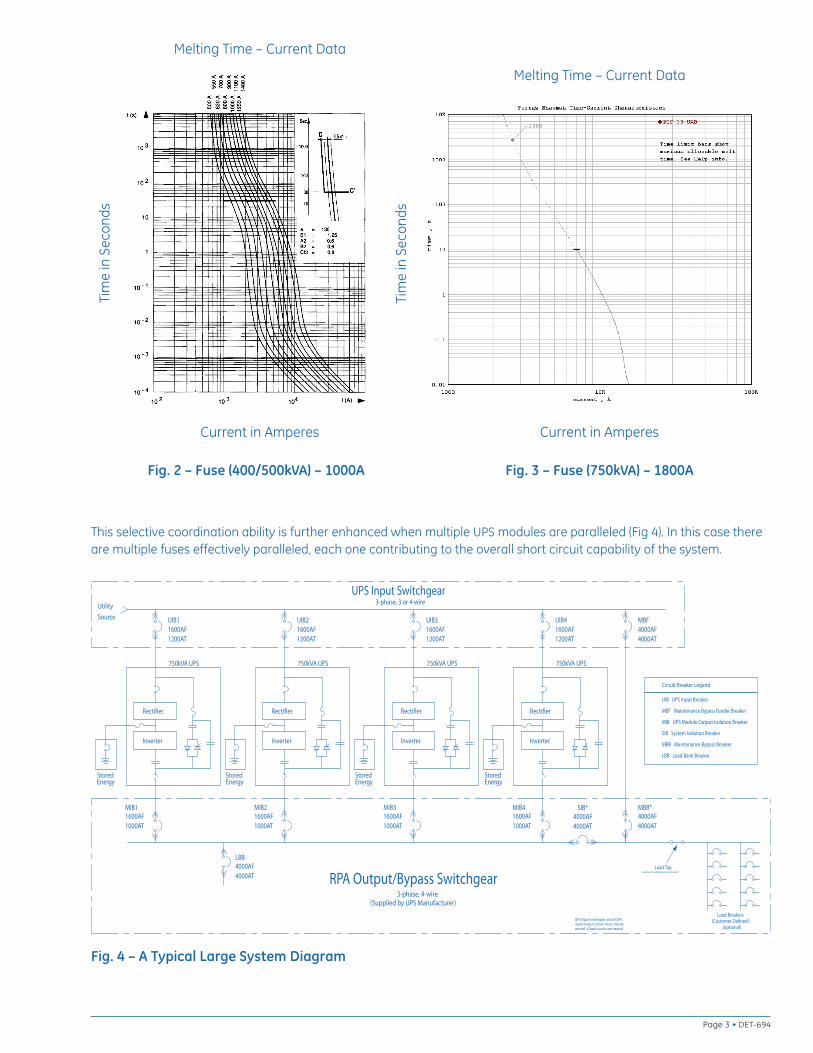
Fig. 2 – Fuse (400/500kVA) – 1000A
This selective coordination ability is further enhanced when multiple UPS modules are paralleled (Fig 4). In this case thereare multiple fuses effectively paralleled, each one contributing to the overall short circuit capability of the system.
Rectifier
Inverter
Utility
Source UIB1
1600AF
1200AT
750kVA UPS
1600AF
1000AT
MIB1
UPS Input Switchgear3-phase, 3 or 4-wire
4000AT
MBF
4000AF
1200AT
UIB2
1600AF
750kVA UPS
Inverter
Rectifier
MIB21600AF
1000AT
750kVA UPS
Inverter
Rectifier
1200AT
1600AF
UIB3
750kVA UPS
Inverter
Rectifier
1200AT
UIB4
1600AF
StoredEnergy
StoredygrenEygrenE
StoredEnergyStored
MBB Maintenance Bypass Breaker
LBB Load Bank Breaker
SIB System Isolation Breaker
MIB UPS Module Output Isolation Breaker
MBF Maintenance Bypass Feeder Breaker
UIB UPS Input Breaker
Circuit Breaker Legend
MBB*
4000AT
4000AF
Load Breakers(Customer Defined)
1000AT
1600AFMIB3
1600AF
1000AT
MIB4
4000AT
4000AFSIB*
4000AT
4000AFLBB
UPS Input switchgear and all UPSinput/output circuits must includeneutral, if load circuits use neutral. (optional)
Load Tap(remove if Load Breakers are not used)
(Supplied by UPS Manufacturer)3-phase, 4-wire
RPA Output/Bypass Switchgear
Fig. 4 – A Typical Large System Diagram
Fig. 3 – Fuse (750kVA) – 1800A
Page 3 • DET-694
Melting Time – Current Data
Current in Amperes
Tim
e in
Sec
onds
Melting Time – Current Data
Current in Amperes
Tim
e in
Sec
onds

During normal operation the UPS operates from normal inputpower, with the inverter feeding the load precisely synthe-sized and controlled power. During an overload event theinverter will continue to power the load up to a maximumoverload rating of 150%. Above this, the inverter will phaseback to maintain the current within safe operating levels. Thisresults in a drop in the inverter output voltage. As the voltagebegins to drop, this drop is sensed and used to initiate atransfer to bypass.
A high-level fault (or short circuit) initially appears as anoverload to the inverter. The difference is that the voltagedrop is very fast. The UPS control circuits sense the rate ofchange of voltage (dv/dt) as well as the absolute voltagedrop and use this information to initiate a transfer to bypassbefore the voltage drops appreciably. Once the fault hasbeen transferred to bypass the internal fuses will limit andinterrupt the fault current, protecting the static switch andother automatic bypass components.
The test source was calibrated to supply 100kA of faultcurrent to the test equipment configuration, including allcables to the UPS module and the shorting breaker.
The UPS equipment was connected to the source and atthe load with the recommended cables as designed fornormal operation. A 30-ampere (enclosure ground fuse),non-delay-type cartridge fuse was connected from theUPS enclosure to Phase B of the test source. The purposeof this fuse is to verify there has been no electrical arcingto the UPS enclosure during the test.
The short-circuit withstand tests on both SG 500kVA andSG 750kVA UPS units were witnessed by UL.
Short Circuit Withstand Test (from UL 891)The Short Circuit Withstand Test is to be conducted at therated voltage corresponding to the maximum short-circuitrating of the equipment. The test circuit is to be closed onthe equipment with all switches, output-circuit protectivedevices, and all the main overcurrent-protective devices orshort-circuit current limiters, integral or separate, in the fullyclosed position. For magnetically operated devices, the mag-net is to be held closed electrically. If the enclosure is pro-vided with a door or cover, it is to be closed during the test
Following the Short-Circuit-Withstand Test, the equipmentshall comply with UL 1778 Paragraph 47, the DielectricVoltage-Withstand Test.
The Short Circuit Withstand Test is initiated by energizingthe UPS and then closing the shorting breaker on the outputof the UPS. The breaker is closed after the UPS has stabilizedin normal operation.
Short Circuit Closing Withstand Test (from UL 891)The Short Circuit Closing Withstand Test is to be conductedat the rated short circuit current corresponding to the maxi-mum rated voltage of the equipment. The sample may bea previously untested sample or the one used for the ShortCircuit Withstand Test described above. The test proceduresand conditions are to be identical to those for the ShortCircuit Withstand Test. With all circuit breakers connectedinto the test circuit and with the main overcurrent-protectivedevice, integral or separate, in the fully closed position, eachswitching device of the equipment is to be closed on thetest circuit.
Following the Short-Circuit-Closing-Withstand Test, theequipment shall comply with UL 1778 Paragraph 47, theDielectric Voltage-Withstand Test.
The Short Circuit Closing Withstand Test is initiated by closingthe shorting breaker on the output of the UPS module priorto energizing the UPS. After the breaker is closed, power isapplied to the UPS input and the UPS is allowed to power-up into the short circuit.
System Operation
Test Source Calibration
Test Connections
Testing Scope
Test Procedures
DET-694 • Page 4

Qualification Requirements (from UL 891)After the equipment has been tested under any of the shortcircuit conditions described, the results are acceptable ifthe equipment is effectively in the same mechanical conditionas prior to the test, and if:
a) There is no permanent distortion or displacement of abus bar or strap that would reduce an electrical spacingto less than 75 percent of its original values.
b) A bus bar insulator or support or cable restraint hasnot separated into two or more pieces. Also there shallbe no cracks appearing on opposite sides of a baseand no cracks, including surface cracks, running thefull length or width of the support. Other cracks, chips,or the like, which are not considered to reduce thestructural integrity of the support may be used if theresulting spacings are not reduced to less than 75percent of it original values.
c) The enclosure ground fuse has not opened
d) The enclosure or part of the enclosure such as a filler plate,door, or the like, has not been damaged nor displaced tothe extent that a live part is accessible per UL 1778Paragraph 7 Protection of Users and/or 39 Protectionof Service Personnel.
e) No conductor pulls out of a terminal connector, andthere is no damage to the conductor insulation or tothe conductor.
f) Complies with the Dielectric Withstand Test
Short Circuit Withstand TestThis test was conducted at 480VAC using a source calibratedto provide 100kA to the test configuration (Fig. 5). The testcircuit was closed on the UPS with all switches, protectivedevices and/or short-circuit current limiters, in fully closedposition. All enclosure doors and covers were closed duringthe test. Immediately following the Short Circuit WithstandTest, the UPS equipment was verified to comply with UL 1778Paragraph 47, Dielectric Voltage-Withstand Test. The currentlimiting fuses were then replaced, and the UPS was verifiedto be fully functional.
Short Circuit Closing Withstand TestThis test was conducted at 480VAC using a source calibratedto provide 100kA to the test configuration (Fig. 5). The testUPS was previously used for the Short Circuit Withstand Testdescribed above. The test procedures and conditions wereidentical to those for the Short Circuit Withstand Test. Withall circuit breakers connected into the test circuit and withthe main over current-protective device in the fully closedposition, each switching device of the UPS was closed on thetest circuit. Immediately following the Short Circuit ClosingWithstand Test, the UPS equipment was verified to complywith UL 1778 Paragraph 47, Dielectric Voltage-WithstandTest. The current limiting fuses were then replaced, and theUPS was verified to be fully functional.
Test Results
30A EnclosureGround Fuse
ShortingBreaker
UPS Under Test
480V,100kA,Source
Fig. 5 – Test Circuit
Page 5 • DET-694
DET-694 • Page 6
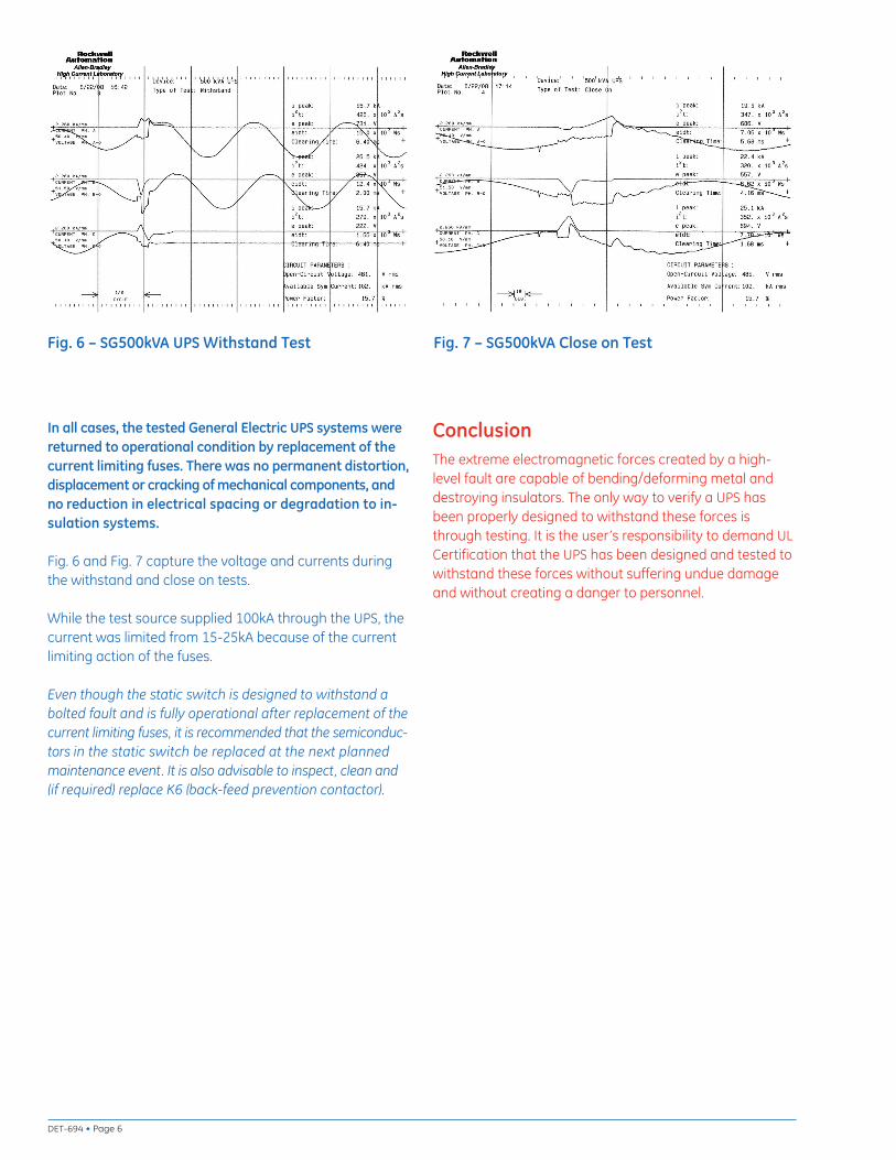
The extreme electromagnetic forces created by a high-level fault are capable of bending/deforming metal anddestroying insulators. The only way to verify a UPS hasbeen properly designed to withstand these forces isthrough testing. It is the user’s responsibility to demand ULCertification that the UPS has been designed and tested towithstand these forces without suffering undue damageand without creating a danger to personnel.
ConclusionIn all cases, the tested General Electric UPS systems werereturned to operational condition by replacement of thecurrent limiting fuses. There was no permanent distortion,displacement or cracking of mechanical components, andno reduction in electrical spacing or degradation to in-sulation systems.
Fig. 6 and Fig. 7 capture the voltage and currents duringthe withstand and close on tests.
While the test source supplied 100kA through the UPS, thecurrent was limited from 15-25kA because of the currentlimiting action of the fuses.
Even though the static switch is designed to withstand abolted fault and is fully operational after replacement of thecurrent limiting fuses, it is recommended that the semiconduc-tors in the static switch be replaced at the next plannedmaintenance event. It is also advisable to inspect, clean and(if required) replace K6 (back-feed prevention contactor).
Fig. 6 – SG500kVA UPS Withstand Test Fig. 7 – SG500kVA Close on Test

Page 7 • DET-694

DET-694 (1/10)
GE Digital Energy – Power Quality830 W 40th Street, Chicago, IL 60609 USA800 637 1738 www.gepowerquality.com
Information subject to change without notice. Please verify all details with GE. © 2010 General Electric Company All Rights Reserved
Withstand Rating – The rating that defines the ability ofthe unit to withstand the thermal and electromagnetic effectsof short circuit currents for a set period of time.
Peak Let-through Current – The maximum instantaneouscurrent through the protective device during the totalclearing time.
I2T Rating – The measure of heat energy developed withina circuit during the fuse's clearing. It can be expressed as“melting I2t”, “arcing I2t” or the sum of them as “clearing I2t”.“I” stands for effective let-through current (RMS), which issquared, and “t” stands for time of opening, in seconds.
Current Limiting Fuse – A fuse incorporating the ability tolimit the maximum current during a fault.
Total Clearing Time – The time measured from the beginningof an overcurrent event, until the current is totally interrupted.For a fuse, this includes both melting and arcing time.
DefinitionsUL Label Sample
Short Circuit Current Rating100kA RMS Symmetrical Amperes
480V maximum
Short Circuit Current Rating65kA RMS Symmetrical Amperes
480V maximum