upm 17110: ^online analyzers for gas quality … iii online analyzers for gas quality measurement...
TRANSCRIPT

22 – 23 February 2017 Houston, TX
Copyright 2017, Letton Hall Group. This paper was developed for the UPM Forum, 22 – 23 February 2017, Houston, Texas, U.S.A., and is subject to correction by the author(s). The contents of the paper may not necessarily reflect theviews of the UPM Forum sponsors or administrator. Reproduction, dis tribution, or storage of any part of this paper for commercial purposes without the written consent of the Letton Hall Group is prohibited. Non-commercialreproduction or distribution may be permitted, provided conspicuous acknowledgment of the UPM Forum and the author(s) is made. For more information, seewww.upmforum.com.
UPM 17110: “Online Analyzers for Gas Quality Measurement in
Gas Production Areas”
Author: Murray Fraser, GC Product Manager, Envent Technologies LLC

Outline: Online Analyzers for Gas Quality Measurement inGas Production Areas
1 ABSTRACT Flow Measurement verses Gas Quality Measurement
2 Low Cost Spot Sampling for Gas Quality Measurement
3 Online Analyzers for Gas Quality Measurement
4 CONCLUSIONS
3
I ABSTRACT
When the term “Measurement” is used in the Oil & Gas Industry it usually refers to Flow Measurement. This paper will discuss Analytical Measurements in Natural Gas sometimes referred to as “Gas Quality Measurements.” The goal of this paper will be to add some perspective to Gas Quality Measurements to help engineering and operations with decisions about application, operation and maintenance of on-line process analyzers. The emphasis will be on practical applications for on-line Process Analyzer technologies in upstream gathering systems such as wellheads, tie-ins, pipeline interconnects and custody transfer locations. Installation and operational “best-practices” will be discussed in addition to technical considerations when applying various sensor technologies to ensure successful installations.

Production Measurement Installations- Flow Measurement verses Gas Quality Measurement
• Flow Measurement- an Orifice meter run, a flow computer and transmitters for P, DP, T.
• Compositional measurements (analyzers)- not as rugged and can be expensive to purchase and maintain.
• Availability of instrumentation and measurement technicians tasked with maintaining analyzers.
• Cost benefit of having valuable information from analyzers verses the added complexity of maintaining analyzers.

Orifice Meter Run for custody transfer Flow Measurement

6
II Low Cost Manual Sampling for Gas Quality Measurement
• Cost/Benefit of continuous measurement of H2S, CO2, H20 and BTU verses low cost solutions
• Manual sampling for natural gas with offsite GC Analysis to C6+• A small cylinder is filled with gas that is assumed to be
representative of the flowing natural gas intended for offsite analysis• Typically a 2-5 day delay for sampling, transportation and offsite
analysis.

7Manual Sampling with sample cylinder and isolation valves

Stain Tubes for Spot Measurement of Impurities
• Low-cost alternative for H2S, CO2 and H2O measurement• Not suitable for BTU measurement.• Minimal upfront capital cost and do not require a significant
amount of ongoing maintenance or training.• Measurement is a rough indication at single point in time and is
not suitable for custody transfer.• Operator must visually observe the stain inside a glass tube that
correlates to the scale indicating the concentration of a given component in natural gas.
• Stain tube accuracy +/- 30% verses analyzer accuracy of +/- 2%.• Convenient verses accuracy.

9Stain tube showing visual stain relative to H2S or H20 concentration with measurement scale printed on a glass tube

10
Portable Analyzers for Remote Analysis
• Suitable for low power
• Measurement of H2S H2S, H20 or CO2
• Can include rechargeable DC batteries
• Can include and Sample Conditioning
• May be an alternative to stain tubes

11
III Online Analyzers for Gas Quality MeasurementSample Conditioning Systems for Process Analyzers
• Very important to ensure they are installed correctly and maintained. • Installation and maintenance of the Sample Conditioning System (SCS) is critical• The purpose of an SCS is to deliver a “representative” sample from the process (under line
conditions) to the analyzer.• Most analyzers operate at ambient pressure and temperature while the gas is sampled at
line conditions IE high pressure and some temperature unrelated to ambient. The SCS must:
1. Reduce pressure2. Measure/control a small sample flow3. Filter the gas before the analyzer4. Switch streams if necessary in multi-stream applications5. Provide for certified calibration gas (calibration or validation)
12
Joule-Thomson Effect
When pressure is reduced gas will cool approximately 7F for every 100 psig of pressure drop. This is referred to as the Joule-Thomson effect (JT effect). If the SCS is to deliver a representative sample of 1050 BTU gas at 90F and 500psig to an H2S, CO2 or H2O analyzer the JT effect is minimal.
90-(5x7)= +55F gas temp.
If the SCS is to deliver a representative sample of 1300 BTU at 90F and 2000 psig to a BTU Gas Chromatograph (GC) the JT effect can cause a huge error in BTU measurement.
90-(20X7)= -50F gas temp.
At this temperature the heavier C2+ hydrocarbons will be dropping out into the liquid phase and will be filtered out in the SCS. In this case a representative sample will not be delivered to the analyzer

13
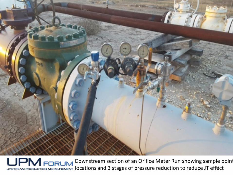
Sample Point Selection
• Downstream section of an Orifice Meter Run
• Requires a small probe inserted into the flowing stream
• Sampling from the flowing stream verses liquids
• Improves accuracy and analyzer reliability with minimal cost
Orifice Meter Run showing downstream sample point locations
14
Downstream section of an Orifice Meter Run showing sample point locations and 3 stages of pressure reduction to reduce JT effect

15
Sample Point Location
• 1280 BTU gas @ 1200 psig and 110F
• Dual stage pressure regulator at sample point
• Third stage pressure regulator at the analyzers
• Heat tracing @ 10 watts per foot to counteract the JT Cooling effect and maintain a single vapor-phase sample.
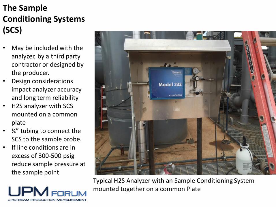
The Sample Conditioning Systems (SCS)
• May be included with the analyzer, by a third party contractor or designed by the producer.
• Design considerations impact analyzer accuracy and long term reliability
• H2S analyzer with SCS mounted on a common plate
• ¼” tubing to connect the SCS to the sample probe.
• If line conditions are in excess of 300-500 psig reduce sample pressure at the sample point
Typical H2S Analyzer with an Sample Conditioning System mounted together on a common Plate

17
H2S Analyzers
• H2S and CO2 Removal at Amine Sweetening processes
• Validates pipeline gas quality specifications of less than 4 parts per million (ppm) H2S and % CO2
• Custody transfer locations to a midstream processing plant or a gas transmission company
• Typical measurement ranges for H2S analysis are trace levels of 0-10 or 0-20 parts per million (ppm).

18
CO2 analyzers
• Blending applications to meet a CO2 specification
• Low CO2 producing wells blended with high CO2 wells to optimize overall production from multiple wells
• Amine Sweetening for CO2 removal• Typical measurement ranges for CO2
analysis are 0-5% or 0-10% CO2 in Natural Gas
• Both CO2 and H2S are removed as part of the Amine sweetening process and a single analyzer may be able to measure both

19
Sensor Technologies
• CO2 measurements with Near Infrared sensors
• H2S measurements with• Electrochemical based sensors• Tuneable Diode Lasers (TDL)
based sensors• Lead Acetate Tape based optical
sensors. • The lead acetate tape method most
common due to simplicity and measurement is specific to H2S. alone without interferences.
• H2O measurements with• TDL based sensors• Conductive Polymer based
sensors• Aluminum Oxide based sensors

20
Sensor Technologies- H2S Analyzers
Lead Acetate Tape
• H2S stain on Lead Acetate tape. The stain is a selective reaction to H2S only without interference from Mercaptans.
• Each stain represents one 5-10 minute analysis window
• The sensor relies on a unique chemical reaction that occurs only between the lead acetate tape and H2S.
• This reaction turns the color of the tape from white to dark brown. By looking at the rate of change of the reaction very accurate sensitive measurements can be made down to parts per billion levels.
21
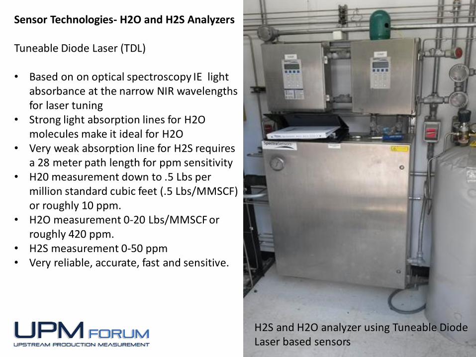
Sensor Technologies- H2O and H2S Analyzers
Tuneable Diode Laser (TDL)
• Based on on optical spectroscopy IE light absorbance at the narrow NIR wavelengths for laser tuning
• Strong light absorption lines for H2O molecules make it ideal for H2O
• Very weak absorption line for H2S requires a 28 meter path length for ppm sensitivity
• H20 measurement down to .5 Lbs per million standard cubic feet (.5 Lbs/MMSCF) or roughly 10 ppm.
• H2O measurement 0-20 Lbs/MMSCF or roughly 420 ppm.
• H2S measurement 0-50 ppm• Very reliable, accurate, fast and sensitive.
H2S and H2O analyzer using Tuneable Diode Laser based sensors
22
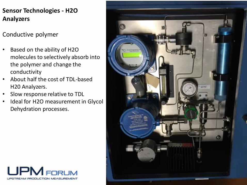
Sensor Technologies - H2O Analyzers
Conductive polymer
• Based on the ability of H2O molecules to selectively absorb into the polymer and change the conductivity
• About half the cost of TDL-based H20 Analyzers.
• Slow response relative to TDL• Ideal for H2O measurement in Glycol
Dehydration processes.

23
Analyzers- Bundled Measurements
• Bundled measurements with H2S, H2O and O2 analyzers
• Common plate sharing a Common Sample Conditioning Systems for analysis of a single stream in a production gathering.
• Ideal for pipeline interconnects or delivery points between a producer and a Midstream Processor.
24
BTU Analyzers or BTU Gas Chromatographs
• Not usually found in production measurement due to the high cost and increased maintenance
• Requires bottled Helium carrier gases and trained personnel with an instrument or measurement background
• Cost/Benefit between cost, reliability and analyzer maintenance verses the uncertainty associated with manual sampling at large volume custody transfer sales points.
• Used in Midstream or Gas Transmission operations where accuracy and maintenance are important
• Production revenue is based on flowing energy, not volume.
Flowing Energy = Volume (SCFH) X Energy (BTU/FT3)

C6+ BTU Gas Chromatographs with Sample Conditioning Systems for Custody Transfer BTU Measurement

26
Total Gas Quality system installed at a custody Transfer station
• Left Side• BTU GC for high
BTU analysis to 1400 BTU
• Right Side• Trace H2S
measurement 0-20 ppm
• Trace H2O measurement 0-20Lbs/MMSCF (0-420 PPM
• Trace O2 measurement 0-100 ppm

27
Summary
1. There are a variety of options for Gas Quality Measurements in production operations from Stain Tubes to BTU Chromatographs. All these options require proper sampling in order to yield accurate results and avoid high maintenance issues.
2. The importance of Sample Conditioning Systems for online gas analyzers cannot be overstated. This is not an expensive part of the overall cost but without proper design, installation and maintenance of the sample systems analyzer accuracy and reliability will be reduced. The potential benefits of online analysis for Gas Quality will be lost and the analyzers themselves can become a expensive to maintain. Most Analyzers found in production measurement are capable of operating accurately and reliably for decades with just a little routine maintenance.
3. Whenever the results of gas quality analyzers are in question the sample conditioning system should provide a quick easy way to reference check the analyzer against a certified calibration standard not a stain tube.