uplift and subsidence associated with the great aceh...
TRANSCRIPT

Uplift and subsidence associated with the great Aceh-Andaman
earthquake of 2004
Aron J. Meltzner,1 Kerry Sieh,1 Michael Abrams,2 Duncan C. Agnew,3
Kenneth W. Hudnut,4 Jean-Philippe Avouac,1 and Danny H. Natawidjaja5
Received 20 June 2005; revised 5 October 2005; accepted 22 November 2005; published 15 February 2006.
[1] Rupture of the Sunda megathrust on 26 December 2004 produced broad regions ofuplift and subsidence. We define the pivot line separating these regions as a first step indefining the lateral extent and the downdip limit of rupture during that great Mw � 9.2earthquake. In the region of the Andaman and Nicobar islands we rely exclusively onthe interpretation of satellite imagery and a tidal model. At the southern limit of the greatrupture we rely principally on field measurements of emerged coral microatolls. Upliftextends from the middle of Simeulue Island, Sumatra, at �2.5�N, to Preparis Island,Myanmar (Burma), at �14.9�N. Thus the rupture is �1600 km long. The distance fromthe pivot line to the trench varies appreciably. The northern and western Andaman Islandsrose, whereas the southern and eastern portion of the islands subsided. The NicobarIslands and the west coast of Aceh province, Sumatra, subsided. Tilt at the southern end ofthe rupture is steep; the distance from 1.5 m of uplift to the pivot line is just 60 km. Ourmethod of using satellite imagery to recognize changes in elevation relative to sea surfaceheight and of using a tidal model to place quantitative bounds on coseismic uplift orsubsidence is a novel approach that can be adapted to other forms of remote sensing andcan be applied to other subduction zones in tropical regions.
Citation: Meltzner, A. J., K. Sieh, M. Abrams, D. C. Agnew, K. W. Hudnut, J.-P. Avouac, and D. H. Natawidjaja (2006), Uplift and
subsidence associated with the great Aceh-Andaman earthquake of 2004, J. Geophys. Res., 111, B02407,
doi:10.1029/2005JB003891.
1. Introduction
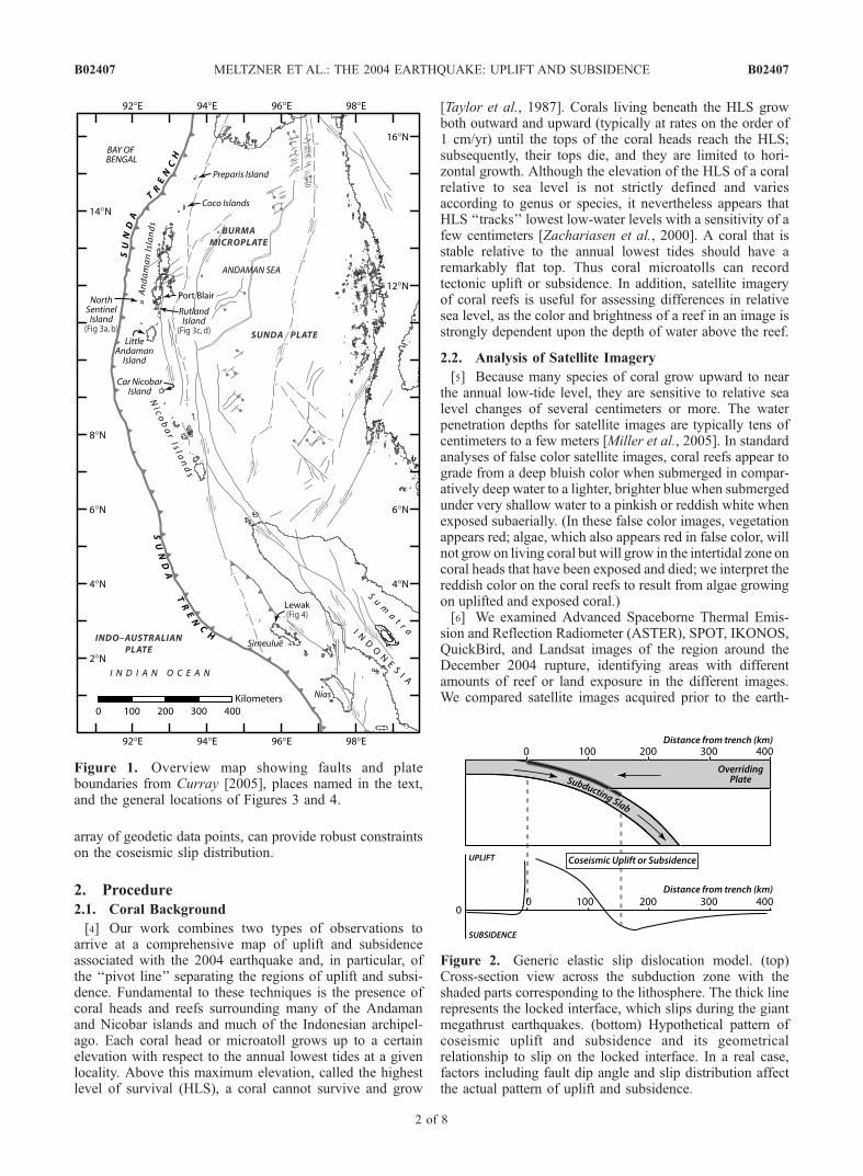
[2] The 26 December 2004 Mw � 9.2 Aceh-Andamanearthquake resulted from slip on the subduction interfacebetween the Indo-Australian plate and the Burma microplatebelow the Andaman and Nicobar islands and Aceh prov-ince, Sumatra (Figure 1). The distribution of aftershocks(e.g., from U.S. Geological Survey, available at http://neic.usgs.gov/neis/poster/2004/20041226.html) suggeststhat the rupture extended over a distance of 1500 km(measured parallel to the arc), but seismic inversions forthis event are nonunique and cannot resolve many details ofslip, especially along the northern portion of the rupture[e.g., Ammon et al., 2005]. Furthermore, considering thatslip north of �9�N appears to have generated little or noseismic radiation [Lay et al., 2005; Ammon et al., 2005],seismic inversions will only provide a minimum constraint
on the extent and amount of slip, and geodetic inversionswill be required to provide a maximum (and perhaps moreaccurate) constraint. However, inversions of the sparsegeodetic data that were available prior to this study providedonly limited constraints on the amount and distribution ofslip [e.g., Subarya et al., 2006].[3] In this paper, we combine satellite imagery and
ground observations to map the extent of coseismic upliftand for some locations to constrain or estimate the magni-tude of uplift or subsidence. In general, for a subductionmegathrust earthquake, coseismic deformation of the upperplate can be modeled using an elastic slip dislocation model[e.g., Plafker and Savage, 1970; Plafker, 1972; Natawidjajaet al., 2004]; one simple model is shown in Figure 2. To afirst order approximation, during the interseismic period theportion of the upper plate overlying the locked subductioninterface is gradually depressed, while the region landwardof the locked fault zone bows upward slightly; then, duringthe earthquake the region above the updip portion of therupture recovers the elastic strain stored during the inter-seismic period and experiences sudden coseismic uplift,whereas the downdip end of the rupture and adjacentregions subside. A small fraction of the coseismic upliftmay reflect permanent strain accumulation in the forearcregion. Although no modeling is presented in this paper, theregion of coseismic uplift approximates the north-to-southrupture extent and demarcates a minimum downdip width offaulting. Resolution of the pattern of uplift, using a dense
JOURNAL OF GEOPHYSICAL RESEARCH, VOL. 111, B02407, doi:10.1029/2005JB003891, 2006
1Tectonics Observatory, Division of Geological and Planetary Sciences,California Institute of Technology, Pasadena, California, USA.
2Jet Propulsion Laboratory, California Institute of Technology,Pasadena, California, USA.
3Scripps Institution of Oceanography, University of California, SanDiego, La Jolla, California, USA.
4U.S. Geological Survey, Pasadena, California, USA.5Research Center for Geotechnology, Indonesian Institute of Sciences,
Bandung, Indonesia.
Copyright 2006 by the American Geophysical Union.0148-0227/06/2005JB003891$09.00
B02407 1 of 8
array of geodetic data points, can provide robust constraintson the coseismic slip distribution.
2. Procedure
2.1. Coral Background
[4] Our work combines two types of observations toarrive at a comprehensive map of uplift and subsidenceassociated with the 2004 earthquake and, in particular, ofthe ‘‘pivot line’’ separating the regions of uplift and subsi-dence. Fundamental to these techniques is the presence ofcoral heads and reefs surrounding many of the Andamanand Nicobar islands and much of the Indonesian archipel-ago. Each coral head or microatoll grows up to a certainelevation with respect to the annual lowest tides at a givenlocality. Above this maximum elevation, called the highestlevel of survival (HLS), a coral cannot survive and grow
[Taylor et al., 1987]. Corals living beneath the HLS growboth outward and upward (typically at rates on the order of1 cm/yr) until the tops of the coral heads reach the HLS;subsequently, their tops die, and they are limited to hori-zontal growth. Although the elevation of the HLS of a coralrelative to sea level is not strictly defined and variesaccording to genus or species, it nevertheless appears thatHLS ‘‘tracks’’ lowest low-water levels with a sensitivity of afew centimeters [Zachariasen et al., 2000]. A coral that isstable relative to the annual lowest tides should have aremarkably flat top. Thus coral microatolls can recordtectonic uplift or subsidence. In addition, satellite imageryof coral reefs is useful for assessing differences in relativesea level, as the color and brightness of a reef in an image isstrongly dependent upon the depth of water above the reef.
2.2. Analysis of Satellite Imagery
[5] Because many species of coral grow upward to nearthe annual low-tide level, they are sensitive to relative sealevel changes of several centimeters or more. The waterpenetration depths for satellite images are typically tens ofcentimeters to a few meters [Miller et al., 2005]. In standardanalyses of false color satellite images, coral reefs appear tograde from a deep bluish color when submerged in compar-atively deep water to a lighter, brighter blue when submergedunder very shallow water to a pinkish or reddish white whenexposed subaerially. (In these false color images, vegetationappears red; algae, which also appears red in false color, willnot grow on living coral but will grow in the intertidal zone oncoral heads that have been exposed and died; we interpret thereddish color on the coral reefs to result from algae growingon uplifted and exposed coral.)[6] We examined Advanced Spaceborne Thermal Emis-
sion and Reflection Radiometer (ASTER), SPOT, IKONOS,QuickBird, and Landsat images of the region around theDecember 2004 rupture, identifying areas with differentamounts of reef or land exposure in the different images.We compared satellite images acquired prior to the earth-
Figure 1. Overview map showing faults and plateboundaries from Curray [2005], places named in the text,and the general locations of Figures 3 and 4.
Figure 2. Generic elastic slip dislocation model. (top)Cross-section view across the subduction zone with theshaded parts corresponding to the lithosphere. The thick linerepresents the locked interface, which slips during the giantmegathrust earthquakes. (bottom) Hypothetical pattern ofcoseismic uplift and subsidence and its geometricalrelationship to slip on the locked interface. In a real case,factors including fault dip angle and slip distribution affectthe actual pattern of uplift and subsidence.
B02407 MELTZNER ET AL.: THE 2004 EARTHQUAKE: UPLIFT AND SUBSIDENCE
2 of 8
B02407

quake with images acquired between 28 December 2004and 26 March 2005 (we looked at images acquired as late as15 August 2005 for Car Nicobar). After stretching andnormalizing the color distribution in each image we reliedon changes in the color and brightness of the reefs amongthe images to assess the relative levels of reef exposure.Fortunately, in most cases these differences in color andbrightness were pronounced enough to be fairly insensitiveto small variations in the overall color representations of theimages. We then used a tidal model (discussed in AppendixA) to determine the relative sea surface height (SSH) at eachlocation at the acquisition time of each image. The 2suncertainty of the tidal model is roughly ±10 cm, so thecalculated difference between two SSHs for a given locationshould be accurate to �14 cm or better. However, a ±14 cm
(2s) uncertainty associated with the overall satellite imagerymethod would be conservative; because we have only usedimage comparisons in which the difference in color orbrightness is unambiguous, this effectively places a ‘‘buffer’’of at least a few centimeters on our stated maximum orminimum bounds. Hence an appropriate 2s uncertainty fora stated bound should be significantly less than 14 cm.Nonetheless, because we cannot quantify the aforemen-tioned ‘‘buffer,’’ we will retain the conservative 14 cm(2s) uncertainty for use in this paper.[7] The sensitivities of the satellite imagery method and
of the tidal model were verified by comparing the apparentrelative exposures among preearthquake images in numer-ous locations where multiple images were acquired prior tothe earthquake. In looking only at images acquired between2000 and 2004, we could neglect both interseismic verticaldeformation and potential growth of the corals, whichshould be well within the uncertainty of the tidal model.Presumably, any differences in reef color or brightnessamong these images should be due solely to differencesin the tides. In support of both the method and the tidalmodel, SSH differences as small as 5–10 cm (less than thestated 2s uncertainty) were commonly recognizable amongthe images of a particular location, with lower SSHscorresponding to more brightly colored reefs.[8] In order to document uplift of a reef we looked for a
postearthquake image with more reef exposure than apreearthquake image of the same area taken at a lower tide;in that case, the difference in SSH between the two imagescan be taken as a minimum constraint on the amount ofuplift. Similarly, to document subsidence, we looked for apreearthquake image with more reef exposure than a post-earthquake image at a lower tide; in this case, the differencein SSH is a minimum constraint on the amount of subsi-dence. An example of each exercise is presented in Figure 3.In addition, we were also able to demonstrate subsidence inwell-drained coastal areas that were not regularly floodedprior to December 2004 but which have been submergedsince the earthquake.
2.3. In Situ Analysis of Coral Microatolls
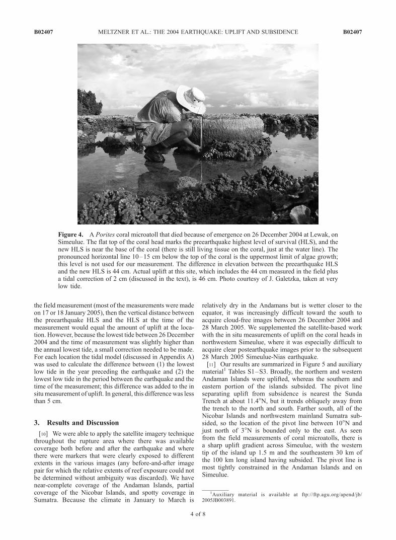
[9] In addition to the satellite-based observations a set offield measurements of uplift was made on emerged coralheads around Simeulue Island, off the coast of Sumatra, byK. Sieh, D. H. Natawidjaja, J. Galetzka, and others (e.g., seeFigure 4). Prior to the 26 December 2004 earthquake eachof these corals was living, and the tops of each coral headcoincided with the preearthquake HLS. During the earth-quake these corals were uplifted, and the portions of eachcoral head now exposed to air would have been killed. Overthe following days and weeks each time a new low tide wasreached, an additional lower portion of the microatollwas exposed and died. For each microatoll a measurementwas made of the vertical distance between the (now dead)top of the coral head and the present HLS, which wasreadily identifiable in the field by the pattern of algaegrowth; algae will not grow on living corals, but it wasobserved in many places to grow immediately above thecoral HLS, extending as much as a half meter above thecoral HLS. If the annual lowest tide (in the year precedingthe earthquake) was equal to the lowest low tide thathappened to occur in the time between the earthquake and
Figure 3. (a) Preearthquake and (b) postearthquakeAdvanced Spaceborne Thermal Emission and ReflectionRadiometer (ASTER) images of North Sentinel Island,showing emergence of the coral reef surrounding the island.The tide was 30 ± 14 cm lower in the preearthquake image(acquired 21 November 2000) than in the postearthquakeimage (acquired 20 February 2005), requiring a minimumof 30 cm of uplift at this locality. Observations from anIndian Coast Guard helicopter on the northwest coast of theisland suggest that the actual uplift is on the order of 1–2 mat this site [Bilham et al., 2005]. (c) Preearthquake and (d)postearthquake ASTER images of a small island off thenorthwest coast of Rutland Island, 38 km east of NorthSentinel Island, showing submergence of the coral reefsurrounding the island. The tide was higher in thepreearthquake image (acquired 1 January 2004) than inthe postearthquake image (acquired 4 February 2005),requiring subsidence at this locality. The pivot line must runbetween North Sentinel and Rutland islands. Note that thescale for the North Sentinel Island images differs from thatfor the Rutland Island images.
B02407 MELTZNER ET AL.: THE 2004 EARTHQUAKE: UPLIFT AND SUBSIDENCE
3 of 8
B02407
the field measurement (most of the measurements were madeon 17 or 18 January 2005), then the vertical distance betweenthe preearthquake HLS and the HLS at the time of themeasurement would equal the amount of uplift at the loca-tion. However, because the lowest tide between 26 December2004 and the time of measurement was slightly higher thanthe annual lowest tide, a small correction needed to be made.For each location the tidal model (discussed in Appendix A)was used to calculate the difference between (1) the lowestlow tide in the year preceding the earthquake and (2) thelowest low tide in the period between the earthquake and thetime of the measurement; this difference was added to the insitu measurement of uplift. In general, this difference was lessthan 5 cm.
3. Results and Discussion
[10] We were able to apply the satellite imagery techniquethroughout the rupture area where there was availablecoverage both before and after the earthquake and wherethere were markers that were clearly exposed to differentextents in the various images (any before-and-after imagepair for which the relative extents of reef exposure could notbe determined without ambiguity was discarded). We havenear-complete coverage of the Andaman Islands, partialcoverage of the Nicobar Islands, and spotty coverage inSumatra. Because the climate in January to March is
relatively dry in the Andamans but is wetter closer to theequator, it was increasingly difficult toward the south toacquire cloud-free images between 26 December 2004 and28 March 2005. We supplemented the satellite-based workwith the in situ measurements of uplift on the coral heads innorthwestern Simeulue, where it was especially difficult toacquire clear postearthquake images prior to the subsequent28 March 2005 Simeulue-Nias earthquake.[11] Our results are summarized in Figure 5 and auxiliary
material1 Tables S1–S3. Broadly, the northern and westernAndaman Islands were uplifted, whereas the southern andeastern portion of the islands subsided. The pivot lineseparating uplift from subsidence is nearest the SundaTrench at about 11.4�N, but it trends obliquely away fromthe trench to the north and south. Farther south, all of theNicobar Islands and northwestern mainland Sumatra sub-sided, so the location of the pivot line between 10�N andjust north of 3�N is bounded only to the east. As seenfrom the field measurements of coral microatolls, there isa sharp uplift gradient across Simeulue, with the westerntip of the island up 1.5 m and the southeastern 30 km ofthe 100 km long island having subsided. The pivot line ismost tightly constrained in the Andaman Islands and onSimeulue.
Figure 4. A Porites coral microatoll that died because of emergence on 26 December 2004 at Lewak, onSimeulue. The flat top of the coral head marks the preearthquake highest level of survival (HLS), and thenew HLS is near the base of the coral (there is still living tissue on the coral, just at the water line). Thepronounced horizontal line 10–15 cm below the top of the coral is the uppermost limit of algae growth;this level is not used for our measurement. The difference in elevation between the preearthquake HLSand the new HLS is 44 cm. Actual uplift at this site, which includes the 44 cm measured in the field plusa tidal correction of 2 cm (discussed in the text), is 46 cm. Photo courtesy of J. Galetzka, taken at verylow tide.
1Auxiliary material is available at ftp://ftp.agu.org/apend/jb/2005JB003891.
B02407 MELTZNER ET AL.: THE 2004 EARTHQUAKE: UPLIFT AND SUBSIDENCE
4 of 8
B02407

[12] Resolution of slip at the northernmost end of therupture is based upon a single datum at Preparis Island(Figure 5). Unfortunately, the only preearthquake ASTERimage of Preparis Island is marred by high atmosphericwater content, which affects the color of the image. Whilewe do not feel this warrants discarding the datum, and whileanalysis of a (lower resolution) Landsat image of the region
acquired on 11 January 2002 also supports minor (20–30 cm) uplift, we concede that this datum is not as robust asthe majority of our imagery-based observations. Attempts toperform a comparable analysis using Envisat syntheticaperture radar (SAR) images were inconclusive (E. Fielding,personal communication, 2005; M. Tobita, personal com-munication, 2005).[13] Concerns about the northernmost data point aside,
our observations suggest that the 26 December 2004 ruptureextended from under Simeulue Island northward to PreparisIsland of Myanmar (Burma), near latitude 15�N. Althoughdifferent authors have measured the length of the rupturedifferently, measured parallel to the arc (as opposed to alonga straight line connecting the rupture endpoints), the ruptureis �1500 km long if it extends from northern Simeulue tolatitude 14�N, and it is �1600 km long if it extends to 15�N.Our preferred northern limit (15�N) is at least 100 km northof the northern extent of rupture suggested by aftershocklocations (e.g., from the U.S. Geological Survey) and byinversions of seismic data [e.g., Ammon et al., 2005].However, in addition to the uplift directly over the rupturepatch, minor uplift would be expected on the updip edge aswell as beyond the northern and southern edges of therupture (V. Gahalaut, personal communication, 2005). Ifreal, the small amount of uplift at Preparis Island does notrequire that slip along the underlying fault plane propagatedthat far north, only nearly so.[14] We must also consider the possibility of interseismic
and postseismic slip being included in our observations.While the amount of interseismic slip that may haveoccurred within the period of our observations (less than5 years) is probably a negligible fraction of the coseismicslip, postseismic slip may be significant. For example,continuous GPS data from the SAMP (Sampali) site nearMedan along the northeast coast of Sumatra reveal a clearrecord of coseismic slip and postseismic relaxation: Thedaily time series from SAMP shows a coseismic horizontaldisplacement of 13.8 cm which increased logarithmically byabout 15% over 15 days and by about 25% over 60 daysfollowing the earthquake [Subarya et al., 2006]. Similarly,Vigny et al. [2005] report that Phuket, Thailand, moved1.25 times the initial coseismic displacement there duringthe first 50 days after the earthquake, and Gahalaut et al.[2006] observed that during the period 11–22 January2005, Port Blair moved horizontally by 3.5 cm in thesame direction as that of the coseismic displacement.Hence our result at each location may be dependent uponthe date of the postearthquake observation. Instead ofattempting to model the separate contributions of coseis-mic and postseismic slip to each of our observations, wesimply present the dates of each observation along withthe respective datum (Tables S1–S3), and we leave it tothe discretion of any users of our data to model the dataas they see fit.[15] In addition to postseismic slip following the 2004
earthquake, coseismic slip from an additional earthquakemay have been captured by our imagery observations onSimeulue island. While we did not examine images ofSimeulue captured after the 28 March 2005 earthquake,an earthquake of Mw 7.3 occurred in central Simeulue on 2November 2002 [DeShon et al., 2005]. At the four sites onSimeulue where we determined from imagery that there was
Figure 5. Summary map showing minimum constraintson uplift or subsidence from satellite imagery, as well asfield measurements of uplift and subsidence on Simeulue.Also shown are faults from Curray [2005] and our bestestimate of the location of the pivot line. The pivot line isshown as a solid thick black line where its location is moretightly constrained and as a dashed line where it is morepoorly constrained. Estimate of subsidence at Busung,Gusong Bay, Simeulue, is from R. Peters (http://walrus.wr.usgs.gov/news/reportsleg1.html). The four imagery-based uplift constraints on Simeulue (pink circles) spanboth the 2002 and 2004 earthquakes and thus representminimum net uplift for the two events. See text and TableS1 for more details.
B02407 MELTZNER ET AL.: THE 2004 EARTHQUAKE: UPLIFT AND SUBSIDENCE
5 of 8
B02407

uplift (pink circles on Simeulue in Figure 5), the preearth-quake images were all acquired prior to the November 2002earthquake. (More details are provided in Table S1.) Hencethe minimum uplift we report at those four sites is actuallyminimum net uplift that occurred during and between the2002 and 2004 earthquakes. Uplift values determined fromin situ microatoll measurements (Table S2), however, areclearly attributable to the 2004 earthquake. At a few sites incentral Simeulue the coral microatolls record multiple upliftevents. In those cases, the earlier uplift is on the order of�20 cm or less, and we tentatively attribute it to the 2002earthquake.[16] We should note that only at a few localities were we
able to provide both maximum and minimum constraints onthe amount of uplift or subsidence; in most cases we wereable to provide only minimum constraints on uplift orsubsidence. This is because the remote sensing method islimited by the tidal range and, in particular, by the range ofSSH among the satellite images that were acquired; in theAndaman and Nicobar islands this range is typically 1 m orless, and in Sumatra this range is typically less than 0.5 m.In any case where the amount of uplift or subsidenceexceeded the SSH range, this method can only provide aminimum bound on the amount of tectonic elevationchange. Information from other sources [e.g., Bilham etal., 2005] suggests that elevation changes (uplift or subsi-dence) of several meters were widespread throughout theaffected region. Hence any minimum bounds on uplift orsubsidence stated in this paper should not be construed torepresent or approximate the actual uplift or subsidence atthat location; only the sign of the elevation change (up ordown) at a location, and hence the constraints on the pivotline, should be considered robust. We must also cautionagainst attempts to interpret any trends among the uplift (red)points or among the subsidence (blue) points in Figure 5.That a stated minimum uplift at one point might be greaterthan a stated minimum uplift at a second point does notimply that the uplift at the first point is greater than the upliftat the second point.[17] In an attempt to provide some ground truth to the
satellite imagery method and to our results we compared theresults presented in Table S1 with recently released cam-paign GPS vertical vectors from 16 sites in the Andamanand Nicobar islands [Jade et al., 2005; Gahalaut et al.,2006] and a handful of sites in Sumatra [Subarya et al.,2006]. For each of the GPS data located within roughly50 km of at least one satellite imagery observation (i.e., forall of the GPS data from the Andaman and Nicobars but foronly a few of the Sumatra data), we compared the GPSvertical vector to the closest imagery-based data. Ourobservations and inferences using satellite imagery andthe tidal model were almost without exception consistentwith the GPS data. At only two sites were the campaignGPS vertical vectors beyond the maximum or minimumbounds derived from our work.[18] At one of the sites with discrepancy, HAVE on
Havelock Island, Andaman Islands (12.03�N, 92.99�E),Jade et al. [2005] calculate an uplift of 0.6 ± 2.5 cmthat they infer represents the coseismic displacement andpostseismic movement through February 2005. They sub-tracted 15 months of inferred interseismic motion (whichhad a negligible vertical component) from the record, as
the last preearthquake site occupation occurred in Septem-ber 2003. The result, 0.6 ± 2.5 cm, is barely beyond theminimum subsidence of 3 to 4 cm allowed at the nearestsites, 4 to 9 km away, based on images acquired on 1January 2004 and 4 February 2005 (Table S1). However,the reported value of Jade et al. [2005] may be suspect.Gahalaut et al. [2006] occupied station GG (Govindgarh;12.036�N, 92.983�E), only �1 km from HAVE, in March2004 and January 2005, covering a shorter period of timeand thereby allowing a more robust determination of thecoseismic displacement vector. Their result, �18 ± 2 cm,is consistent with the imagery-based observations. Thereason for the discrepancy between Gahalaut et al. [2006]and Jade et al. [2005] is unclear, but we note that ourresults for that vicinity are entirely consistent with theformer and they are consistent with the latter within thestated (albeit conservative) ±14 cm (2s) uncertainty result-ing from the tide model.[19] At the other site with discrepancy, Hut Bay (HB) on
Little Andaman Island (10.696�N, 92.569�E), Gahalaut etal. [2006] report a coseismic elevation change of �26 ±2 cm (i.e., 26 cm of subsidence), with successive siteoccupations in March 2004 and January 2005. In contrast,satellite images acquired on 1 January 2004 and 3 January2005 (Table S1) indicate that the entire island of LittleAndaman rose, with the eastern part (including Hut Bay)up at least 18 cm, although the nearest imagery-baseddatum to Hut Bay is more than 10 km away. Again,however, the GPS value may be suspect. Also usingcampaign GPS measurements, Earnest et al. [2005] deter-mined that there was 36 cm of uplift at Hut Bay betweenAugust 2004 and early 2005, although the dates of theirsite occupations are not specified. Their result appears tobe in conflict with that of Gahalaut et al. [2006] but is incomplete agreement with our constraints. The reason forthe discrepancy between Gahalaut et al. [2006] andEarnest et al. [2005] is unclear, but in further support ofthe imagery-based observations over the GPS observationsof Gahalaut et al. [2006], Bilham et al. [2005] citeeyewitness reports of substantial (1–2 m, though thismay be exaggerated) coseismic uplift at Hut Bay.
4. Conclusions
[20] We combine satellite imagery and ground observa-tions of emerged and submerged coral reefs and microatollsand invoke a tidal model to resolve geodetic deformationassociated with the 26 December 2004 Aceh-Andamanearthquake. We constrain the location of the pivot lineseparating regions of uplift and subsidence. Most of therupture of the underlying megathrust must be west of thisline. This line implies a rupture width that varies fromslightly greater than 80 km to slightly greater than 120 kmand a rupture length of �1600 km, at least 100 km longerthan that suggested by aftershock locations and byseismic inversions to date. Our method of using satelliteimagery to recognize apparent color differences in coralreefs, of correlating these color differences with differ-ences in elevation relative to SSH, and of using a tidalmodel to place quantitative bounds on coseismic uplift orsubsidence is a novel approach that can be adapted toother forms of remote sensing and can be applied to other
B02407 MELTZNER ET AL.: THE 2004 EARTHQUAKE: UPLIFT AND SUBSIDENCE
6 of 8
B02407

subduction zones in the tropics and perhaps elsewhere inthe world.
Appendix A: Determination of Tide Heights
[21] In a comparison of preearthquake and postearth-quake satellite imagery of reefs or coastal areas, in orderto ascertain with certainty whether a particular areaexperienced uplift or subsidence, any variation in SSHdue to tidal influences must be considered. In addition, asdescribed in the body of this paper, if differences in theextent of reef exposure can be identified among theimages of a location, then the difference in SSH betweenthe images can be used to constrain the amount of upliftor subsidence.[22] In order to determine the tidal height at each location
of interest at the acquisition time of each satellite image
we used the software package NLOADF [Agnew, 1997],along with harmonic tidal constituents extracted from theOregon State University Regional Tidal Solutions (regionalmodels based on satellite observations) for the Bay ofBengal and for Indonesia [Egbert and Erofeeva, 2002](available at http://www.coas.oregonstate.edu/research/po/research/tide/region.html; hereinafter referred to as theBay of Bengal and Indonesia models, respectively). TheBay of Bengal model covers the Andaman and Nicobarislands, and the Indonesia model covers Sumatra and itsoffshore islands, so these two models are sufficient for ourstudy. The regional inverse solutions (including the Bay ofBengal and Indonesia models) have about the sameresidual magnitudes as the global solution TPXO.6 forthe open ocean, but the regional solutions fit the datasignificantly better for areas with complex coastlines andbathymetry and are consequently preferred.
Figure A1. (top) Plot of the observed tides at Phoenix Bay Fisheries Jetty (PBFJ), Port Blair, AndamanIslands, for the period 31 December 2004 to 7 January 2005. (Day 0.0 corresponds to 1 January 2005,0000:00 UTC.) (bottom) Residuals of the differences between the observations and the predictions of theOregon State University (OSU) Bay of Bengal model, between the observations and the predictions ofthe International Hydrographic Bureau (IHB) model, and between the respective predictions of the OSUBay of Bengal and IHB models. Each plot of residuals is offset vertically for clarity; also note thedifference in the scale of the residual plots (Figure A1, bottom) in comparison to that of the observations(Figure A1, top). A significant portion of the residuals may be due to measurement errors or toimprecision in the tide gauge at PBFJ; still, the residuals fall within a 2s uncertainty of ±10 cm or less.
B02407 MELTZNER ET AL.: THE 2004 EARTHQUAKE: UPLIFT AND SUBSIDENCE
7 of 8
B02407

[23] To verify the harmonic tidal constituents extractedfrom the Bay of Bengal model, we compared the predictionsof these constituents for Port Blair (in the Andaman Islands)for several arbitrary time periods with direct tide observa-tions at the Phoenix Bay Fisheries Jetty (PBFJ) in Port Blair(Figure A1) andwith the predictions from three ground-basedsources: the Indian Tide Tables (ITT), the InternationalHydrographic Bureau (IHB), and the Admiralty Tide Tables(ATT). (See Pugh [2004, chapter 3] for a discussion ofharmonic tidal constituents.) The ITT are published by theSurvey of India and consist of predictions of times and heightsof high and low tides at Port Blair, based on their (unknown tous) harmonic constituents, which are in turn based on tidegauge data; the predictions for January 1965 were readdirectly from the tables. The harmonic constituents of theIHB for Port Blair were derived from harmonic analysis of41 years of tide gauge data (1880–1920) from the ITT; theyare taken from International Hydrographic Bureau [1953,sheet 159]. The ATT are published by the British Admiraltyand consist of harmonic constituents for Port Blair, also basedon tide gauge data; the constituents for 1996 were chosen forthis comparison. Note that the applicability of the ITT, theIHB, and the ATT predictions is limited to Port Blair and thefew other locations for which tide gauge data exist; to assessthe behavior of tides elsewhere in the Andaman and Nicobarislands and in Sumatra, a model based on satellite observa-tions is more robust.[24] Overall, the ITT and the IHB predictions should
provide the closest approach to ‘‘ground truth’’ for theactual tidal heights, and the predictions for Port Blair ofthe ITT, the IHB, and the Bay of Bengal model areremarkably consistent with one another, lending credibilityto the Bay of Bengal model. The standard deviation of thedifferences between the tidal observations at PBFJ and thepredictions of the Bay of Bengal model is on the order of±5 cm; likewise, for the year 2004 the standard deviationof the difference between the respective predictions of theBay of Bengal model and the IHB constituents is roughly±5 cm, and the maximum difference is under 20 cm. Thesevalues should provide a sense of the maximum likelyerrors in the Bay of Bengal model’s predictions, at leastfor Port Blair. The ATT predictions differ somewhat fromthe others, so they will not be considered further. The Bayof Bengal model appears to be the best for use throughoutthe Andaman and Nicobar islands; the only location forwhich we did not use this model is for Port Blair itself,where the IHB tidal constituents should be most reliable.By extension of the foregoing discussion we consideredthe Indonesia regional model to be better than any ground-based local predictions for use throughout Sumatra.
[25] Acknowledgments. We thank Mohamed Chlieh, Chen Ji, RichBriggs, and Rob McCaffrey for assistance and many insightful discussions.We are grateful to John Galetzka, Imam Suprihanto, and BambangSuwargadi for data collection and invaluable field support in Indonesiaand to Hidayat and Samsir of Derazona Air Services, our helicopter pilotand mechanic. We are very appreciative of Chris Goldfinger for collectingand sharing satellite imagery and of Roger Bilham for sharing data andmaking his manuscripts available to us, which benefited us tremendously.We thank JoAnne Giberson and Shaun Healy for ongoing GIS support. Wealso thank Vineet Gahalaut, Roger Bilham, and an anonymous reviewer forhelpful reviews that led to substantial improvements in the paper. Weacknowledge the use of QuickBird imagery made freely available byDigitalGlobe, and the use of IKONOS and SPOT 5 images acquired,processed, and made freely available by CRISP, National University of
Singapore. This research was supported in part by the Gordon and BettyMoore Foundation and by NASA grant NAG5-10406. This is CaltechTectonic Observatory contribution 23.
ReferencesAgnew, D. C. (1997), NLOADF: A program for computing ocean-tideloading, J. Geophys. Res., 102, 5109–5110.
Ammon, C. J., et al. (2005), Rupture process of the 2004 Sumatra-Andaman earthquake, Science, 308, 1133–1139.
Bilham, R., E .R. Engdahl, N. Feldl, and S. P. Satyabala (2005), Partial andcomplete rupture of the Indo-Andaman plate boundary 1847–2004,Seismol. Res. Lett., 76, 299–311.
Curray, J. R. (2005), Tectonics and history of the Andaman Sea region,J. Asian Earth Sci., 25, 187–228.
DeShon, H. R., E. R. Engdahl, C. H. Thurber, and M. Brudzinski (2005),Constraining the boundary between the Sunda and Andaman subductionsystems: Evidence from the 2002 Mw 7.3 Northern Sumatra earthquakeand aftershock relocations of the 2004 and 2005 great earthquakes, Geo-phys. Res. Lett., 32, L24307, doi:10.1029/2005GL024188.
Earnest, A., C .P. Rajendran, K. Rajendran, R. Anu, G. M. Arun, and P. M.Mohan (2005), Near-field observations on the co-seismic deformationassociated with the 26 December 2004 Andaman-Sumatra earthquake,Curr. Sci., 89, 1237–1244.
Egbert, G. D., and S. Y. Erofeeva (2002), Efficient inverse modeling ofbarotropic ocean tides, J. Atmos. Oceanic Technol., 19, 183–204.
Gahalaut, V. K., B. Nagarajan, J. K. Catherine, and S. Kumar (2006),Constraints on 2004 Sumatra earthquake rupture from GPS measure-ments in Andaman-Nicobar islands, Earth Planet. Sci. Lett.,doi:10.1016/j.epsl.2005.11.051, in press.
International Hydrographic Bureau (1953), Tides: Harmonic Constants, Int.Hydrogr. Bur. Spec. Publ., 26, 121 pp., sheets 1–3055.
Jade, S., M. B. Ananda, P. D. Kumar, and S. Banerjee (2005), Co-seismicand post-seismic displacements in Andaman and Nicobar islands fromGPS measurements, Curr. Sci., 88, 1980–1984.
Lay, T., et al. (2005), The great Sumatra-Andaman earthquake of26 December 2004, Science, 308, 1127–1133.
Miller, R. L., C. E. Del Castillo, and B. A. McKee (Eds.) (2005), RemoteSensing of Coastal Aquatic Environments: Technologies, Techniques andApplications, Remote Sens. Digital Image Process., vol. 7, 347 pp.,Springer, New York.
Natawidjaja, D. H., K. Sieh, S. N. Ward, H. Cheng, R. L. Edwards,J. Galetzka, and B. W. Suwargadi (2004), Paleogeodetic records ofseismic and aseismic subduction from central Sumatran microatolls,Indonesia, J. Geophys. Res., 109, B04306, doi:10.1029/2003JB002398.
Plafker, G. (1972), Alaskan earthquake of 1964 and Chilean earthquake of1960: Implications for arc tectonics, J. Geophys. Res., 77, 901–925.
Plafker, G., and J. C. Savage (1970), Mechanism of the Chilean earthquakesof May 21 and 22, 1960, Geol. Soc. Am. Bull., 81, 1001–1030.
Pugh, D. (2004), Changing Sea Levels: Effects of Tides, Weather andClimate, 280 pp., Cambridge Univ. Press, New York.
Subarya, C., M. Chlieh, L. Prawirodirdjo, J.-P. Avouac, R. McCaffrey,Y. Bock, K. Sieh, A. J. Meltzner, and D. H. Natawidjaja (2006),Static deformation of the great Aceh-Andaman earthquake, Nature,doi:10.1038/nature04522, in press.
Taylor, F. W., C. Frohlich, J. Lecolle, and M. Strecker (1987), Analysis ofpartially emerged corals and reef terraces in the central Vanuatu Arc:Comparison of contemporary coseismic and nonseismic with Quaternaryvertical movements, J. Geophys. Res., 92, 4905–4933.
Vigny, C., et al. (2005), Insight into the 2004 Sumatra-Andaman earthquakefrom GPS measurements in southeast Asia, Nature, 436, 201–206,doi:10.1038/nature03937.
Zachariasen, J., K. Sieh, F. W. Taylor, and W. S. Hantoro (2000), Modernvertical deformation above the Sumatran subduction zone: Paleogeodeticinsights from coral microatolls, Bull. Seismol. Soc. Am., 90, 897–913.
�����������������������M. Abrams, Jet Propulsion Laboratory 183-501, California Institute of
Technology, 4800 Oak Grove Drive, Pasadena, CA 91109, USA.D. C. Agnew, Scripps Institution of Oceanography 0225, University of
California, San Diego, 9500 Gillman Drive, La Jolla, CA 92093, USA.J.-P. Avouac, A. J. Meltzner, and K. Sieh, Tectonics Observatory,
Division of Geological and Planetary Sciences, California Institute ofTechnology, Pasadena, CA 91125, USA. ([email protected];[email protected])K. W. Hudnut, U.S. Geological Survey, Pasadena Field Office, 525 South
Wilson Avenue, Pasadena, CA 91106, USA.D. H. Natawidjaja, Research Center for Geotechnology, Indonesian
Institute of Sciences, Komplek LIPI Gd. 70, J1, Bandung 40135, Indonesia.
B02407 MELTZNER ET AL.: THE 2004 EARTHQUAKE: UPLIFT AND SUBSIDENCE
8 of 8
B02407