updownload softwarehandleiding eng
DESCRIPTION
riscoTRANSCRIPT

RISCO Group Upload/Download Software Manual

Important Notice
This guide is delivered subject to the following conditions and restrictions:
This guide contains proprietary information belonging to RISCO Group. Such information is supplied solely for the purpose of assisting explicitly and properly authorized users of the system.
No part of its contents may be used for any other purpose, disclosed to any person or firm, or reproduced by any means, electronic or mechanical, without the express prior written permission of RISCO Group.
The information contained herein is for the purpose of illustration and reference only. Information in this document is subject to change without notice. Corporate and individual names and data used in examples herein belong to their
respective owners.
Copyright © 2007 RISCO Group. All rights reserved.
No part of this document may be reproduced in any form without prior written permission from the publisher.
RISCO Group
Table of Contents
Page 2
Table of Contents
Chapter 1: Introduction.....................................................................................................4
Chapter 2: Hardware Installation .......................................................................................5 2.1 System Requirements ..................................................................................................................... 5 2.2 Hardware Setup .............................................................................................................................. 5
Chapter 3: Software Installation ........................................................................................9 3.1 Installing the Upload/Download Installer Program .................................................................. 9 3.2 Installing DAO .............................................................................................................................. 13
Chapter 4: Getting Started...............................................................................................14 4.1 Activating Upload/Download from Your Windows Desktop ............................................... 14 4.2 About this Software ...................................................................................................................... 15
4.2.1 Your screen........................................................................................................................ 15 4.2.2 How to use Upload/Download software...................................................................... 15
Selecting Options from the Main Menu....................................................................... 15 Entering/Selecting Parameter Information .................................................................. 16 Screen Types .................................................................................................................... 17 Help Menu........................................................................................................................ 17 Tool Bar............................................................................................................................. 18
4.3 How to Proceed............................................................................................................................. 19 4.3.1 Establishing Communication ......................................................................................... 20
Direct ................................................................................................................................. 20 PSTN Remote Connection.............................................................................................. 20 IP Network Connection (ACM)..................................................................................... 20 PSTN Fast Modem Connection Using the ACM Remote Access Service (RAS) .... 21 GSM Connection (Fast Remote) .................................................................................... 22
Chapter 5: Main Menu Bar Options..................................................................................23 5.1 Client Menu (Client Management)............................................................................................. 23
5.1.1 New Client ........................................................................................................................ 24 5.1.2 Find Client......................................................................................................................... 24 5.1.3 Find Next Client ............................................................................................................... 25 5.1.4 Delete Client...................................................................................................................... 25 5.1.5 Save Client......................................................................................................................... 25 5.1.6 Print Client ........................................................................................................................ 25 5.1.7 Backup Database .............................................................................................................. 25 5.1.8 Backup Client.................................................................................................................... 26 5.1.9 Restore Database .............................................................................................................. 26 5.1.10 Restore Clients ................................................................................................................ 26

Page 3
5.1.11 Navigation Arrows ........................................................................................................ 27 5.1.12 Exit.................................................................................................................................... 27
5.2 Options Menu................................................................................................................................ 27 5.2.1 Log in ................................................................................................................................. 27 5.2.2 System Configuration...................................................................................................... 27 5.2.3 Operators........................................................................................................................... 29 5.2.4 History Log ....................................................................................................................... 30 5.2.5 Delete Log.......................................................................................................................... 30 5.2.6 Batch Operations .............................................................................................................. 30 5.2.7 Run Batch .......................................................................................................................... 30 5.2.8 Background Color ............................................................................................................ 31 5.2.9 Screen Lock ....................................................................................................................... 31 5.2.10 Print Options................................................................................................................... 31 5.2.11 Panel Types ..................................................................................................................... 31 5.2.12 Interface Language......................................................................................................... 31 5.2.13 Translation Tool.............................................................................................................. 31
5.3 Installer Menu................................................................................................................................ 32 5.3.1 ProSYS Installer Menu Options...................................................................................... 32 5.3.2 WisDom Installer Menu Options ................................................................................... 35 5.3.3 Orbit‐Pro and Pro‐24 Installer Menu Options.............................................................. 36 5.3.4 Orbit‐6 Installer Menu Options...................................................................................... 38 5.3.5 Orbit‐14 Installer Menu Options.................................................................................... 38
5.4 Access Control Menu (for ProSYS only) .................................................................................... 39 5.5 End User Menu ............................................................................................................................. 39
5.5.1 ProSYS and WisDom End User Menu Options ........................................................... 40 5.5.2 Orbit‐Pro, Pro‐24, Orbit‐6, Orbit‐14 End User Menu Options................................... 42
5.6 Comm (Communications) Menu................................................................................................ 42 5.6.1 Upload Screen................................................................................................................... 42 5.6.2 Upload All ......................................................................................................................... 42 5.6.3 Download Screen ............................................................................................................. 43 5.6.4 Download All.................................................................................................................... 43 5.6.5 Verify Screen ..................................................................................................................... 43 5.6.6 Wait for Call ...................................................................................................................... 43 5.6.7 Dial to Panel ...................................................................................................................... 44 5.6.8 Hand Over......................................................................................................................... 44 5.5.9 Hang Up ............................................................................................................................ 45 5.6.10 Message to LCD Keypad............................................................................................... 45
5.7 Event Log Menu............................................................................................................................ 45 5.7.1 Upload All ......................................................................................................................... 45 5.7.2 Upload Recent .................................................................................................................. 46 5.7.3 View ................................................................................................................................... 46 5.7.4 View From File ................................................................................................................. 46
5.8 Help Menu ..................................................................................................................................... 46

Page 4
Chapter 1: Introduction This manual explains how to use the RISCO Group Upload/Download software supporting RISCO Group Security Systems. By using the Upload/Download software, you can manage the panel database of your clients, you can program any of the panels from your own PC, selecting the features you require from the many described in this manual. You can customize each panel in line with the special requirements of the client. This can be done at the client’s premises with a direct link to a laptop computer, or from a remote location via a phone connection using a modem, GSM or via IP using ACM (available for ProSYS).
Upload/Download software also enables you to coordinate the activities of your operators, as well as maintaining records of both operators’ activities and customized configurations through an on‐line status display. You can upload from the panel to your computer to make changes when needed and then download from your computer to the panel with the new set up that you have prepared.
Before you start, read straight through to the end of chapter 4. This will familiarize you with the conventions used, and prepare you to go ahead with the actual menu options. Section 4.3, How to Proceed, contains a flow chart with the actual steps to be taken and should be consulted before you actually start working with the program.

Chapter 2: Hardware Installation
Page 5
Chapter 2: Hardware Installation 2.1 System Requirements
Computer: Processor: RAM: Available disk space: Operating System:
Minimum required 486 All Pentium processors are suitable Minimum 128 K Minimum 45 MB Windows 98, Windows 2000, Windows XP and Windows NT
Accessories: CD Drive For direct U/D via your laptop PC:
Cable with connectors for the computer and the panel RP296EBA00A: RS232 to the RS485 converter, RP128EUSB00A: USB to the RS485 converter for Orbit‐Pro and above RP205LU for Orbit 5 RP214LU00000A for Orbit 6 & 14
For remote Upload/Download via modem, phone line, GSM or IP connection (according to the type of panel):
Modem: see Systems Configuration in the Options menu. Phone lines at both panel and computer locations GSM: see Systems Configuration in the Options menu. IP connection: see ACM
2.2 Hardware Setup
Programming the security system can be done in several ways according to the type of panel: locally, remotely via modem or GSM, or via IP.
Local: The following diagram is the local system connection:
PC CONTROL PANEL
BUS ADAPTER
R8485

Chapter 2: Hardware Installation
Page 6
To establish direct cable connection from your computer to the panel:
1. Connect the BUS adapter (depending on your panel) to your computer. 2. Connect the 4 pin connector to the socket on the Control Panel main board at the client premises
or directly to the 4‐wire bus at any point. (Make sure the panel is in Ready mode and not in Install mode.)
3. Power up your computer and continue to section 3.2: Installing the Upload/Download software.
Remote: Modem requirements: Use a Hayes compatible modem: Hayes Optima, US Robotics. The following diagram is the overall system connection using a modem:
To establish remote connection from your modem to the panel:
1. Connect the modem to your PC and telephone line according to the above diagram. 2. Check the dial tone on your phone line. 3. After hearing the dial tone, hang up and power up your computer and modem and continue to
section 3.2: Installing the Upload/Download software.
TCP/IP Ethernet Connections (ACM):
The following diagram is the overall system connection between the ProSYS security panel and IP network:
Note: The ACM is compatible with UD software.
PC MODEM
PSTNTELEPHONE
LINE
CONTROL PANEL
PC
ACM
ProSYS CONTROL PANEL
IP
4 WIRE BUS
J1 J2 J3 J4 J5TERMINAL BLOCKS

Chapter 2: Hardware Installation
Page 7
To establish IP network connection using the ACM:
1. Connect the ACM to the Ethernet by plugging an appropriate Ethernet cable plug into the RG‐45 connector on the ACM. For detailed information of mounting and connecting the ACM refer to the ACM manual
Note: When ACM is connected and not in STAND Alone status, you are unable to perform Upload/Download communication via direct or GSM connection.
2. Power up your computer and continue to section 3.2: Installing the Upload/Download software.
PSTN Connection using RAS (Remote Access Service) of the ACM:
PSTN fast remote connection of the ProSYS can be established using a modem located on the ACM (Advanced Communication Module P/N RP128AA0100A). This connection is used if you want to establish a backup connection to the ACM IP connection. The following diagram is the overall system connection using RAS connection:
To establish RAS connection from your computer to the panel:
1. Connect the ACM at the client premises to the PSTN line
Note: The STAND Alone jumper located on the ACM should be set to its default value (no).
2. Modem requirements: Use any modem that supports dialup Internet connection.
GSM/PSTN Upload/Download Fast Remote Connection:
Remote Upload/Download can be performed using the GSM data channel.
Notes:
• Upload / Download via GSM is available only for ProSYS and WisDom panels with an AGM module connected.
• Programming the GSM/GPRS Module can be established with Upload/Download.
• To enable Upload/Download programming over the GSM network the control parameter UD GSM Enable should be enabled in the control panel. Please refer to the panel manuals for more information regarding this parameter.
PC
ACM WITH MODEM
RP128AB0100A
CONTROL PANEL
PSTNTELEPHONE
LINE
MODEM

Chapter 2: Hardware Installation
Page 8
The following diagram is the overall system connection using a GSM modem or PSTN:
To establish GSM modem connection from your GSM/PSTN to the panel:
1. Connect the AGM to the panel BUS connection at the customer premises. 2. Connect the GSM/PSTN modem to your computer. You can use a cellular phone as your
computer modem. RISCO Group recommends Nokia® brand phones with modem. 3. Power up your computer and continue to section 3.2: Installing Upload/Download software.
PC GSM / PSTN
MODEM
AGM
MODULE
CONTROL PANEL
GSM NETWORK
4 WIRE BUS
TELEPHONE LINE CABLE

Chapter 3: Software Installation
Page 9
Chapter 3: Software Installation To receive the Upload/Download software you can contact your local distributor or download it from the RISCO Group website: www.riscogroup.com.
The Upload/Download software includes the following Programs:
Installer – The main software package. DAO – Data Access Object is the auxiliary database software package for those computers
not already equipped with this database capability.
3.1 Installing the Upload/Download Installer Program
To Install Upload/Download Installer:
1. From www.riscogroup.com go to Support & Downloads>Upload/Download software and click Download to download the Upload/Download software to your computer.
2. Double click on the Setup.exe file. The Choose Setup Language dialog box appears.
Choose Setup Language dialog box
Chapter 3: Software Installation
Page 10
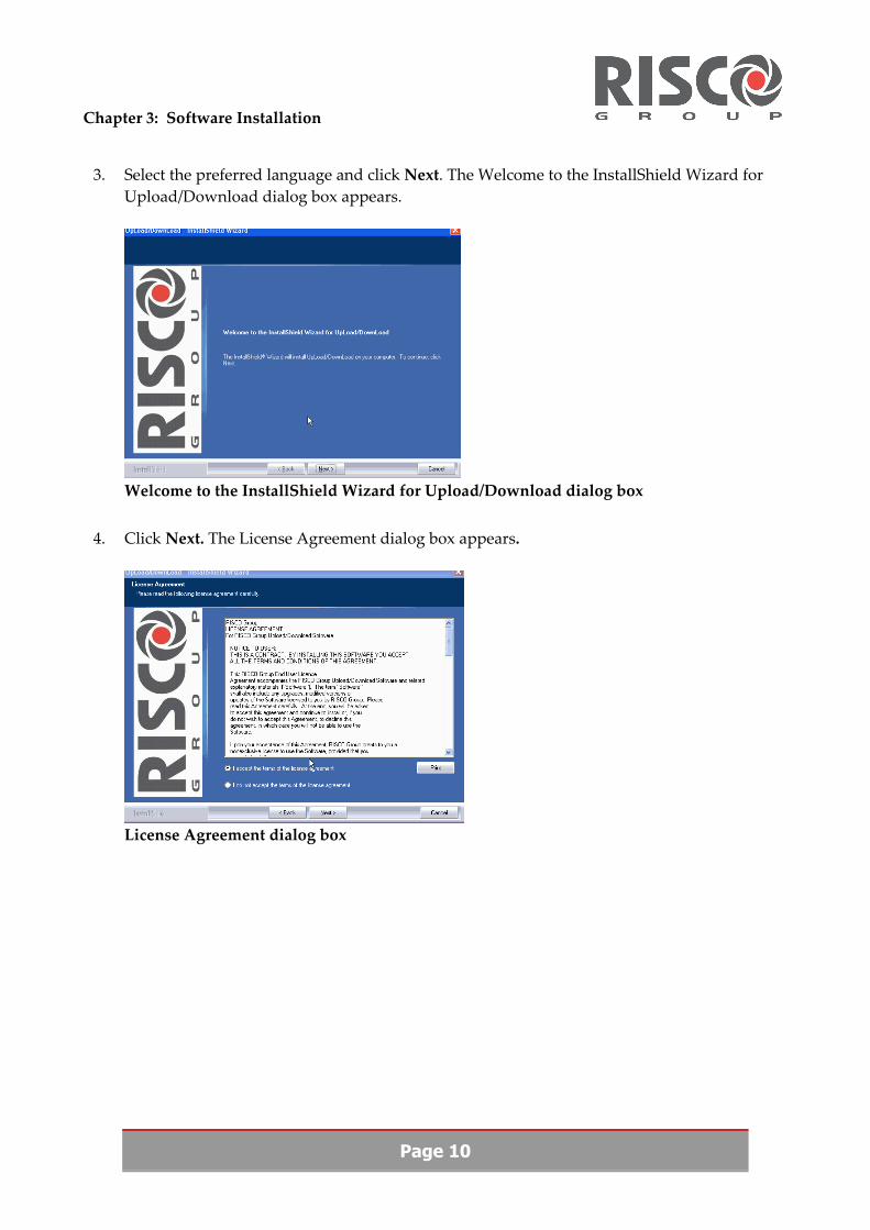
3. Select the preferred language and click Next. The Welcome to the InstallShield Wizard for Upload/Download dialog box appears.
Welcome to the InstallShield Wizard for Upload/Download dialog box
4. Click Next. The License Agreement dialog box appears.
License Agreement dialog box

Chapter 3: Software Installation
Page 11
5. Select the I accept the terms of the license agreement option to accept the terms of the licensing agreement and click Next. The Customer Information dialog box appears.
Customer Information dialog box
6. In the User Name and Company fields type your name and the name of your company. Click Next. Choose the destination folder dialog box appears with a default destination folder. You can change the destination path by selecting an alternative path with the Browse button.
7. Select the Complete option if you would like to download the entire package. If you would like to specify which features you would like to download select the Custom option, the Select features dialog box appears with the following options: Application, Database and Help. Select the feature you want to install and deselect the features you do not want to install by checking the preferred checkboxes and click Next.
8. Click Next to continue. The Ready to Install the Program dialog box appears.
Ready to Install the Program dialog box

Chapter 3: Software Installation
Page 12
9. Click Install to begin the installation. The Welcome to continue InstallShield Wizard for Upload/Download dialog box appears.
Welcome to continue InstallShield Wizard for Upload/Download dialog box
10. If you want to save a previous database select the Yes I have option and browse for the previous database path. If not, select the No, this is my first installation of the Upload/Download software option and click Next. The InstallShield Wizard Complete dialog box appears when installation is complete.
InstallShield Wizard Complete dialog box
11. Before you can start with Upload/Download you need to restart your computer. Click Yes, I want to restart my computer now to do this automatically and click Finish.

Chapter 3: Software Installation
Page 13
3.2 Installing DAO
DAO is a Windows database module that usually is installed as part of the Windows operating system. Sometimes Windows is installed without this module. Without this module, Upload/Download can not be activated properly and error messages appear. Check that DAO is integrated in your system, if not you must install DAO.
To Install DAO:
1. From www.riscogroup.com go to Support & Downloads>Upload/Download software and click the download Microsoft DAO link to download DAO to your computer.
2. Double click on the Jet35sp3.exe file to run it in order to stop current services.
3. Double click on the Setup.exe file and click OK. The Welcome screen appears.
4. Follow the standard Windows installation procedures and accept all the default settings.
5. Double click on the Jet35sp3.exe file to run it in order to update the installation files.
Note: Jet35sp3.exe and Setup.exe are Microsoft files.
6. Activate Upload/Download again and it will function correctly.

Chapter 4: Getting Started
Page 14
Chapter 4: Getting Started 4.1 Activating Upload/Download from Your Windows
Desktop
1. From the Start menu select Programs>Rokonet Upload/Download. The Rokonet menu box appears.
2. Select Upload/Download. The log in dialog box appears.
Log in dialog box
3. Type in the default password: rokonet and click Enter.
Note: The password is case sensitive and must be typed in lower‐case letters. Make sure the caps lock is off!
4. Upload/Download is activated. The Main Client screen appears.
Main Client screen

Chapter 4: Getting Started
Page 15
4.2 About this Software
4.2.1 Your screen
Your screen is divided into 5 areas:
An example of your screen layout
Main menu: There are up to 7 options in the main menu bar in addition to Help. Tool bar: The tool bar consists of icons that provide an alternative to choosing options
through the main menu. The tool bar also displays the name of the screen you have selected as well as the name of the operator.
Upper info bar: Displays the client number, client name and type of panel you are using. Main screen: Displays the features of the particular option you have chosen from the
main menu and sub‐menus. Lower info bar: Displays the time, date and type of panel you are using. The lower info
bar also displays the status of your connection (red – no connection, green – connected).
4.2.2 How to use Upload/Download software
Selecting Options from the Main Menu
There are two ways to select main menu items:
1. Place your cursor on an option in the Main Menu and click to open its drop down menu.
2. Press simultaneously on the Alt key and the underlined letter key of the required main menu item. For example to select the Installer menu press simultaneously the Alt and I keys.
Note: The name of the menu option selected always appears at the top right of either type of screen next to the Tool bar.

Chapter 4: Getting Started
Page 16
Entering/Selecting Parameter Information
The screens contain different ways for entering/selecting information, such as checkboxes, text fields and drop‐down lists.
Note: Enter partition information via the toggle option.
It is also possible to copy information from one cell to another using your mouse:
To use the copy and paste function:
1. Click once on a cell then click with the right mouse button. 2. Select Copy. 3. Click on another cell in the column and again use the right hand mouse button and select Paste. 4. The contents of the first cell appear in the second. 5. To select a complete row, click to the left of the row. The whole row is highlighted in blue. 6. Use copy and paste to move the contents of the entire row. 7. Alternatively, you have the option to drag a row or a cell to adjoining rows and/or cells where
they are duplicated.

Chapter 4: Getting Started
Page 17
Screen Types
TYPE 1 SCREENS TYPE 2 SCREENS
Type 1 screens have check boxes, drop‐down lists and fields to enter parameter information. Type 1 screens contain many parameters grouped together by a common heading colored red and a border, see diagram below:
Type 2 screens resemble a spreadsheet and have some Microsoft Excel features, i.e. copy & paste. To navigate between the cells, use the keyboard arrows or, with your mouse pointer, click into the cell you want to modify with your mouse pointer. The cells appear in 3 colors coded as follows: White: You may change the default data – where shown and/or type in your own required settings. Blue‐Green: These cells contain a drop down list that can be opened by clicking on the arrow on the top right. To select an option, click on it. Pink: These fields are automatically generated from information you enter into other fields
A Type 1 screen
A Type 2 screen
Help Menu
To access the Help menu, type F1. This provides additional information for all menu options. The Help menu screen is divided into 2 sections. On the left side, click on the option that you are checking, the help menu for this appears on the right side.

Chapter 4: Getting Started
Page 18
Tool Bar
The tool bar is situated beneath the main menu. Click on the relevant icon for the desired action. These are the icons:
ICON DEFINITION
New Client
Find Client
Delete Client
Save Client
First Client
Previous Client
Next Client
Last Client
Cut
Copy
Paste
Configuration
Operators
Upload Screen
Download Screen
Dial
Retrieve Default Values
Previous Screen
Last Screen
Next Screen
About
Note: The name of the screen that has been selected and the operatorʹs name are shown next to the tool bar.

Chapter 4: Getting Started
Page 19
4.3 How to Proceed
The instructions in this manual are presented in the order of the main menu bar. Sections and subsections are numbered consecutively. Initial steps to be taken do not coincide exactly with the order of the menus and drop‐down lists. To help you, the following charts show how to proceed with initial operation of the software. The section numbers allow easy reference to the sections of the manual.
After installing the software you can now do the following:
Download a new client file to the control panel:
Activate software (4.3.1)
Select New Client and
type in Client info (see 5.1)
Edit relevant parameters (see 5.1)
EXIT
Download data to
control panel (see 5.6.4)
Communicate with control panel (see 5.2.2)
Type remote access code & ID code (see
5.5)
Upload a new client file from the control panel:
Activate software (see
4.3.1)
Select Client Type (see 5.1)
Select a New Client (see 5.1)
Type remote access code & ID code (see
5.5)
Communicate with clientʹs control panel (see 5.2.2)
Upload data to software (see 5.7.1)
Review system status & parameters
(see 5.5)
SAVE and then EXIT
Select Client Type (see 5.1)

Chapter 4: Getting Started
Page 20
4.3.1 Establishing Communication
There are several different types of connections to the panel, follow the correct procedure according to the physical type of connection you want have:
Direct
To establish direct cable connection from your computer to the panel:
1. Activate the Upload/Download software. 2. In the Client information screen select the Local connection type option (see section 5.1). 3. From the Main menu select Options>System Configuration. The System Configuration dialog
box appears (see section 5.2.2). 4. Enter the relevant Direct Com Port and click OK. 5. Check that communication has been established by setting the time and date (see section 5.5).
Note: The status of the connection appears in the lower bar of your screen. Green means that connection has successfully been established.
6. To disconnect communication, from the Main menu select Comm>Hang up.
IP Network Connection (ACM)
IP connection can be established for the ProSYS panel using the ACM module.
To establish network connection from your ACM card to the panel:
1. Activate the Upload/Download software. 2. In the Client information screen select the Network connection type and fill in the correct ACM
IP Address (see section 5.1).
Note: It is recommended to check that the ACM IP address on your panelʹs keypad is identical to the IP you enter here.
3. From the Main menu select Installer>Communication>ACM and make sure that the ACM IP address is the same address you previously filled in the Client information screen. Fill in the relevant fields (see section 5.3.2).
Note: For detailed information refer to the ACM manual.
4. Check that communication has been established by setting the time and date (see section 5.5).
Note: The status of the connection appears in the lower bar of your screen. Green means that connection has successfully been established.

Chapter 4: Getting Started
Page 21
PSTN Connection Using the ACM Remote Access Service (RAS)
PSTN fast remote connections can be established using RAS (Remote Access Service) connection with the modem located on the ACM (Advanced Communication Module P/N RP128AA0100A). This connection is used if you want to establish a backup connection to the ACM IP connection.
To establish communication via the RAS connection type:
Firstly you must configure your dialup connection in order to connect Upload/Download software to ACM through dialup (modem) connection.
Follow the PSTN dialup connection to ACM procedure:
a. From your desktop open My Network Places. b. Right click on your mouse to open Properties. c. From the Network Tasks select Create a New Connection. The Welcome to the New
Connection Wizard dialog box appears. d. Click Next. The Network Connection Type dialog box appears. e. Select the Connect to the Internet option and click Next. The Getting Ready dialog box appears. f. Select the Setup my connection manually option and click Next. The Internet Connection
dialog box appears. g. Select the Connect using a dialup modem option and click Next. The Select a Device dialog box
appears. h. Select the appropriate modem and click Next. The Connection Name dialog box appears. i. Type ACM in the text field and click Next. The Phone Number to Dial dialog box appears. j. Type your phone number in the text field and click Next. The Connection Availability dialog
box appears. k. Select the preferred option and click Next. The Internet Account Information dialog box
appears. l. Type ppp (Note: small letters) in the User name field and acmppp (Note: small letters) in the
Password and Confirm password fields. Deselect both checkboxes and click Next. The Completing the New Connection Wizard dialog box appears.
m. Click Finish to exit the wizard. n. From your desktop the ACM dialup connection, enter your user name and password and click
Properties. ACM Properties dialog box appears. o. In the Security tab select Advanced (custom settings) options and click Settings. The Advanced
Security Settings dialog box appears. p. Select the unencrypted password (PAP) option in the Allow these protocols option. Click OK
to return to the ACM dialup connection dialog box. q. Enter you username and password and click Dial to check your connection.

Page 22
Secondly, after you have completed the above procedure, from the Client information screen select the RAS option and follow the remote modem connection steps as described for PSTN Remote Connection.
PSTN / GSM Connection (Remote / Fast Remote)
Remote Upload/Download can be performed using the GSM data channel.
To establish PSTN/GSM modem connection from your GSM to the panel:
1. Activate the Upload/Download software. 2. In the Client information screen type in the Panel phone number and select the Remote/Fast
Remote connection type (see section 5.1). 3. From the Main menu select Options>System Configuration. The System Configuration dialog
box appears (see section 5.2.2). 4. Enter the relevant Remote Com Port. 5. Fill in the Modem Setup fields. Make sure that you check the Wait for dial tone checkbox,
update the dialing method and select the correct Modem type from the drop‐down list and click OK.
Note: Select a modem that is compatible with the type of connection you have chosen, from the Modem type drop‐down list.
6. From the Main menu select Installer>Communication>Dialer 1. The Dialer parameters 1 screen opens. When filling in the fields make sure that the U/D GSM enable checkbox is checked (see section 5.3.2).
7. From the Main menu select Installer>Communication>Dialer 2. The Dialer parameters 2 screen opens. When filling in the fields make sure that you fill in the Dial tone wait time field (see section 5.3.2).
8. From the Main menu select Installer>Communication>GSM. Select GSM from the Type drop‐down list. Update the rest of the fields (see section 5.3.2).
Note: For detailed information of GSM parameters refer to the GSM manual.
9. Check that communication has been established, from the Main menu select Comm>Dial to panel or click on the Dial icon. When communication has been established, set the time and date (see section 5.5).
Note: The status of the connection appears in the lower bar of your screen. Green means that connection has successfully been established.

Chapter 5: Main Menu Bar Options
Page 23
Chapter 5: Main Menu Bar Options Note: The number of options in the main menu, sub‐menus and client information screen
varies according to the type of panel you own. The following description of the main menu options is based on the ProSYS panel unless specified otherwise.
5.1 Client Menu (Client Management)
The client info screen appears immediately after you activate the software. The screen includes the panel drop‐down list. The relevant panel type is selected as well as the client number. The screen also includes the following text fields for you to fill in:
Account Insert your own reference – numbers and/or letters Name Full customer name – for your records Phone Customer phone – for your records – with city access
code Panel phone
If your phone system requires a code to access an outside line, enter this access code followed by the area code and phone number exactly as you would dial when calling the panel.
Address Full address for your records City and zip code For your records Comment This is an extra text field for any special information
you may wish to record.
The screen also includes a number of radio buttons. Select the relevant connection type as listed below:
Connection type Remote – connection via phone. Local –connection via direct cable. Network – connection via IP. Fast Remote – connection via GSM network. RAS –fast connection via phone using the ACM with modem . Note: Not all panels and modems possess all these options.
ACM IP Address This is a text field. Insert your IP address if you want a network connection. Note: Only if you have the option of Network connection.

Chapter 5: Main Menu Bar Options
Page 24
The screen also includes a number of fields that are automatically generated and/or updated by the system. These are listed below:
Client Number
This represents the client number. It is automatically generated when setting up a new client (see below) Clicking on the arrows on the Icon bar navigates between the clients, in order of their client number. The system keeps the client number 0001 reserved for display of the default panel screens. When you click on the > navigation arrow, the first few clicks go through the panel options. The client number remains 0001, until you have passed all the panels. The next click then opens client number 0002, the first defined client. The default panel screens under client number 0001 are not modifiable.
Panel The system deals with a number of different panels. Created Updated Printed
These fields are automatically updated by the system.
5.1.1 New Client
To enter a new client:
1. From the main menu select Clients>Client information to enter the Main Client screen, select the default panel screen for the type of panel in use from the Panel drop‐down list.
2. From the main menu bar select Clients>New Client, or from the tool bar, click the New Client
icon. A new client screen appears with the Panel type attribute from your panel selection. The client number automatically takes the next free number. This code number is the number assigned to your new client.
3. Type in all the relevant information for the new client, in the white text fields, as explained above.
5.1.2 Find Client
To find a client in the database:
1. From the main menu bar select Client>Find Client, or from the tool bar, click the Find Client
icon. The Find Client dialog box appears. 2. In the white field, type in a string of words or numbers from the data already entered for the
client you are looking for. This can be a name, part of a name or address or any numerical information such as a phone number or zip code. The default entry is * which includes all clients in you system.

Chapter 5: Main Menu Bar Options
Page 25
3. Click OK. On the basis of your entry, the system searches for the appropriate client. The Client search results dialog box appears with all the options that contain the search criteria.
4. Double click on the client you are searching for to open that clientʹs information. You can also select the client number from the drop‐down list below.
5. Click OK. The clientʹs information screen appears.
5.1.3 Find Next Client
To find the next client in the list, from the main menu select Clients>Find next. The next clientʹs information screen appears.
5.1.4 Delete Client
To delete the currently active and displayed client form the database:
1. From the main menu select Client>Delete Client, or from the tool bar, click the Delete Client icon. The Delete Client dialog box appears.
2. Select the client you wish to delete from your system. The client displayed on the screen is to be deleted.
3. Click the Yes button. The client is deleted.
5.1.5 Save Client
To save client data to the database:
From the main menu bar select Client>Save Client, or from the tool bar, click the Save Client icon. The Client data is saved and stored in the database. (If you have not saved and want to exit the program you will receive a message asking you if you want to save the changes you have made.)
5.1.6 Print Client
To print client data:
1. From the main menu bar select Client>Print Client, or from the tool bar, click the Print icon. The print dialog box appears.
2. Select the client whose data you want to print. 3. Select the printing parameters and click OK. The system prints complete client information
including all system parameters for the client selected.
5.1.7 Backup Database
Backing up the database: To ensure that client data can be restored if your database is inadvertently destroyed, you must make a periodic backup. Backup Database backs up the entire database by saving a copy of the database.

Chapter 5: Main Menu Bar Options
Page 26
To backup the entire database:
1. From the main menu bar select Options>System configuration. In the Backup path field enter the path where you wish to save your backup database. The default path is your C drive. Click OK.
2. From the main menu bar select Client>Backup database. Type the name of the file and click Save.
3. Click Start. A Done message appears when backup is complete. All the data contained in the Upload/Download database is saved.
5.1.8 Backup Client
To backup the data according to the Client List only:
1. From the main menu select Client>Backup Client. The Backup Clients to File dialog box appears with a list of all your clients.
2. Select the relevant client by clicking on the client in the list. To select several clients from the list, press Shift while clicking on additional clients. To unselect a client, click on the relevant client in the list and click Unselect.
3. Click Save. Select the path you where you wish to save this file. The default path is your C drive. Type the name of the file and click Save.
Note: If you are changing versions of the Upload/Download software, the latest version will accept all information saved in the previous version.
5.1.9 Restore Database
Restore Database overrides your existing database and replaces it with the backup database.
To restore the database:
1. From the main menu bar, select Client>Restore database. The Restore database dialog box appears. Select the appropriate file and click Open.
2. The database is restored (copied) to the system.
5.1.10 Restore Clients
Restore Clients adds duplicate clients to the list.
To restore client data:
From the main menu bar, select Client>Restore Client. The Client(s) data is restored to the system database.
Note: The duplicate client that is created will appear in the next available space on the list.

Chapter 5: Main Menu Bar Options
Page 27
Warning: Use the Restore function for data that has been erased from your system only. The restore function does not overwrite existing data but enters the data as new clients.
5.1.11 Navigation Arrows
You can click on the navigation arrows or use the keyboard alternatives shown below to move from client to client.
First client: Ctrl+PgUp Previous client: Shift+PgUp Next client: Shift+PgDn Last client: Ctrl+PdDn
5.1.12 Exit
From the main menu, select Client>Exit to exit the program. (If you have not saved the changes you have made and want to exit the program you will receive a message asking you if you want to save these changes.)
5.2 Options Menu
5.2.1 Log in
The Log in option allows you to log in to the system after another operator has used the system but has not exited it. When you log in you will receive the features you have access to.
To Log in:
From the main menu bar, select Options>Login. The login dialog box appears. Type in your password and click OK. The main client screen appears.
5.2.2 System Configuration
This screen enables you to set up the communication between the Upload/Download and the panel through modem, GSM or direct cable. Your system should be set correctly in order to connect to the panel.
To set the system configuration for connecting to the panel:
From the main menu bar select Options>System Configuration, or from the tool bar, click the
System Configuration icon. The System Configuration dialog box appears. Fill in the fields that apply to you:

Chapter 5: Main Menu Bar Options
Page 28
PARAMETER HOW TO SET
Connection Type:
Remote COM Port (modem) Note: Not relevant for RAS.
Using the arrows, select the COM port number. (Choose either direct COM Port or Remote COM Port.)
Direct COM Port Using the arrows, select the COM port number. (Choose either Direct COM Port or Remote COM Port.)
MS lock Type in a 6 digit code. If the MS lock is not the same as that on the panel, the following fields cannot be uploaded or downloaded:
Installer Code MS Phone Numbers (in Dialer 1) MS Lock Code Default Jumper Y/N
The MS lock in the panel can be changed periodically for security reasons. If it has been changed in the panel, the new MS lock must be typed in here for all the screens to be accessible.
Modem Parameters:
Wait for dial tone Place your cursor in the box and click to insert . Click again to delete.
Rings to answer Click on the arrows to set the number of rings for Callback.
Speaker volume Dialing method Modem type Modem speaker
Click on the arrow to open the drop down list for each of these parameters. Place the cursor on the required option and click to select.
User Modem string For use if a modem type is used and it is not listed in the modem type drop down list. For information about the user modem string – refer to your modem manual.
Backup path The system provides backup options for storing information. The default is C/:. If you use an alternative backup – type in the details in this field. (For more information on alternative backup settings, contact your RISCO Group representative.

Chapter 5: Main Menu Bar Options
Page 29
Code Table Enter the name of the file for using non‐Latin characters in messages to appear on the LCD. For more information about the available files, contact your RISCO Group representative.
5.2.3 Operators
Each person who is authorized to use the Upload/Download software should be registered as an operator within the software. Each operator is assigned a password that he uses when he activates the software. When you activate Upload/Download for the first time, you use the default password. You can have up to 50 operators.
Access to the operators list can be denied to all operators except for the default operator (administrator) listed as no.1
To ensure that only you or authorized personnel have access to your system it is necessary to change the default password, and establish passwords for your operators. This is important as the same default is provided on all new software.
To create new password:
1. From the main menu bar select Options>Operators, or from the tool bar, click the Operators
icon. The Operators screen appears. This screen shows a numbered list. The default operator heads the list with the default password rokonet.
2. Type your name as the default operator. 3. Change the password to one of your choice. Remember that the password is case sensitive. 4. Click OK and this new password replaces rokonet for future activation of the software.
To add operators to the list and customize their access to the system:
1. From the main menu, select Options>Operators. The Operators dialog box appears. Click on a line in the list and type the password and operatorʹs name.
2. Click Authorization to define each operatorʹs access to different features and activities. The Customize User Authorization dialog box appears.
3. Select the relevant checkboxes. In addition to the options that appear you can customize the following according to View and Modify:
System, Communication, Expanders, Zones Accessory Access Control User Operations

Chapter 5: Main Menu Bar Options
Page 30
Click the above optionsʹ buttons and their dialog box appears where you can check which parameters your operators can view and which parameters they can modify. Click OK or Set All if you would like to apply these settings to all your operators.
4. Click OK. You return to the list of operators. Continue adding and/or customizing operators. When you have finished click OK.
5.2.4 History Log
The History log displays all the activities carried out by the operators. It is generated by the system.
To access the History log:
From the main menu, select Options>History log. The History Log dialog box appears displaying the entire history log which includes which operator entered which client screens.
Note: You can view a specified log by typing in the time span, operation type, operators, screens and clients you wish the log to display. If you do not type any specific criteria, the full list of events will be displayed.
5.2.5 Delete Log
To delete the history log:
From the main menu bar, select Options>Delete log. The Delete History log dialog box appears.
Click Yes. All previous activities are removed from the log.
5.2.6 Batch Operations
It is possible to set a group of operations that the Upload/Download software will perform automatically when the Control Panel dials, in one batch. In this way it is possible to postpone the operations for non busy time. These operations and the order that they will be performed include the following: Disarm Partition, Time Set, Upload, Download, Save Status and Arm Partition.
To set a batch operation:
From the main menu bar, select Options>Batch operations. The Batch operations dialog box appears. Select the relevant operations.
5.2.7 Run Batch
Run batch enables you to set the Batch operations to standby up to 24 hours in advance, until the panel call mode arrives.
From the main menu bar select Options>Run Batch. When a call comes from the panel, the ID and Access codes will be verified and then the Batch operation is run according to the settings defined. When the Batch operation is complete, the system terminates communication.

Chapter 5: Main Menu Bar Options
Page 31
You can press <Esc> at any time if you change your mind and wish to cancel the batch operation.
5.2.8 Background Color
You can change the software screen background color. From the main menu, select Options>Background color. The background color dialog box appears. Select the preferred color and click OK.
Note: You cannot change the Client Information and Status screensʹ background color. In these cases you will be unable to select this option as it appears in gray in the sub‐menu.
5.2.9 Screen Lock
The administrator can protect the software from access by locking the screen or disconnecting communication. You can choose to lock the screen or disconnect communication after a certain period of time has passed, when idle or after a certain number of bad login attempts to protect the system from access. From the main menu, select Options>Screen Lock. The Screen Lock\Disconnect Communication dialog box appears. Type the number of minutes or attempts in the different options and click OK. Enter 0 if you do not want to lock the screen.
5.2.10 Print Options
You can set the date and type of client information (name, number) that you wish to appear at the top of the printout. From the main menu, select Options> Print Options. The Print Options dialog box appears select the options and click OK.
5.2.11 Panel Types
You can choose to define which panel types you will see in your Panel list in the Client screen. From the main menu select Options>Panel Types. The Panel List Select dialog box appears. Click on a panel type and use the arrows to move your selection between the Hide and Show lists. Click OK.
Note: This action does not delete the hidden Panel names from your system.
5.2.12 Interface Language
You can change the Upload/Download interface language. From the main menu, select Options>Interface Language. The Language dialog box appears. Choose the preferred language from the drop‐down list and click OK.
5.2.13 Translation Tool
For details refer to your local RISCO Group representative.

Chapter 5: Main Menu Bar Options
Page 32
5.3 Installer Menu
Note: Installer menu options depend on the type of panel you own. Not all the Installer menu options and sub‐options appear for all the panel types. Refer to each panelʹs manual for detailed information of each option.
5.3.1 ProSYS Installer Menu Options System Parameters:
To set the general systemʹs parameters. 1. System From the main menu select Installer>System and one of these options: System
Codes: You can define installer codes such as Grand Master, Installer, Sub‐Installer as well as allocate Upload/Download Remote Access & ID codes. You can define which fields to block via the MS Lock.
Dialer 1: To set the Control Panelʹs Digital Communicator dialing parameters to the Central Station.
Dialer 2: To set the rest of the Control Panel Digital Dialer parameters.
ACM: To set the ACM parameters. Note: You must first update your IP in the client information screen before setting ACM parameters.
2. Communication You can set the systemʹs communication parameters. From the main menu select Installer>Communication and one of these options:
GSM: To set the GSM parameters.
Keypads:
Zone expanders:
UO expanders:
Power supplies:
Event loggers:
3. Expanders From the main menu select Installer>Expanders and one of these options:
WL button expander:
To set the type and configuration of each expander in your system.

Chapter 5: Main Menu Bar Options
Page 33
5.3.1 ProSYS Installer Menu Options Printer:
Access control:
Voice module:
Digital key expander:
Siren:
Bus test: For performing bus test and reviewing the test result.
Bus scan: For reading the list of all the accessories connected to the systemʹs Bus.
Test bells and keypads:
For sending a command to test the bells and keypads.
Power supply:
For testing the 3A switched power supplies connected to the system.
Siren: For testing the sirens (ProSound) connected to the BUS.
Bus detectors:
For testing the bus detectors, such as: Industrial Lunar, WatchOut.
GSM: For testing AGM.
4. Diagnostics You can send a command to perform different actions on the system. From the main menu select Installer>Diagnostics and one of these options: Note: Communication with the panel must be open.
PKR: For testing PKR (Proximity Key Reader).
Zone parameters:
For setting a list of zones, labels, their partition, type, sound etc.
Zone crossings:
For setting the correlation and time intervals between pairs of zones.
Zone self‐test:
Soak test:
For testing zones.
5. Zones For setting zone configurations, from the main menu select Installer>Zones and one of these options:
BUS detectors:
For setting special parameters for BUS detectors, such as: Industrial Lunar and WatchOut.

Chapter 5: Main Menu Bar Options
Page 34
5.3.1 ProSYS Installer Menu Options Reporting Codes:
For setting the Reporting codes in the system to the Monitoring station.
Special Reporting Codes:
For setting the Special Reporting codes in the system. The 2 hex digits are converted to 3 decimal digits (For use with ADEMCO Contact ID and SIA as additional codes to the built in conversion table of the panel
Auto SIA Codes:
The Auto SIA codes option is accessed. When this option is selected a message box opens asking you if you are sure that you want to send Auto SIA Codes Yes/No? If you do, click Yes. A new message box opens showing Auto SIA Codes command sent successfully. Note: It is recommended to perform Reset Codes before performing Auto SIA Codes. Note: It is important to complete the panel configuration before sending the Auto SIA Codes command. Selecting Auto SIA ID codes sends a command to the panel to set all report codes according to the panel configuration. Warning: Report codes are not updated automatically in the software. To update, select Upload all. It is important to complete the panel configuration before sending the Auto SIA Codes.
06. Report Codes For setting the reporting codes in the system, from the main menu select Installer>Report Codes and one of these options: Note: Most Report Codes have a corresponding Restore Code which, following a reported event, restores the settings to normal. These Codes are 2‐character codes. The numbers 00 appear as the default in the cell fields of the codes. To set them, type 2 characters from 0 to 9 and/or from A to F. The codes you type replace the default in the cell field.
Auto contact ID codes:
The Auto SIA codes option is accessed. When this option is selected a message box opens asking you if you are sure that you want to send Auto Contact ID Codes Yes/No? If you do, click Yes. A new message box opens showing Auto Contact ID Codes command sent successfully. Note: It is recommended to perform Reset Codes before performing Auto contact ID codes. Note: It is important to complete the panel configuration before sending the Auto Contact ID Codes command. Selecting Auto Contact ID codes sends a command to the panel to set all report codes according to the panel configuration. Warning: Report codes are not updated automatically in the software. To update – do Upload all. It is important to complete the panel configuration before sending the Auto Contact ID command.

Chapter 5: Main Menu Bar Options
Page 35
5.3.1 ProSYS Installer Menu Options Reset Codes:
For resetting all the reporting codes for the Monitoring station.
7. Utility Outputs For setting the Utility outputs in the system, from the main menu select Installer>Utility Outputs.
8. User Codes For setting the User codes in the system, from the main menu select Installer>User Codes.
9. WL Button For setting the WL button parameters in the system, from the main menu select Installer>WL Button.
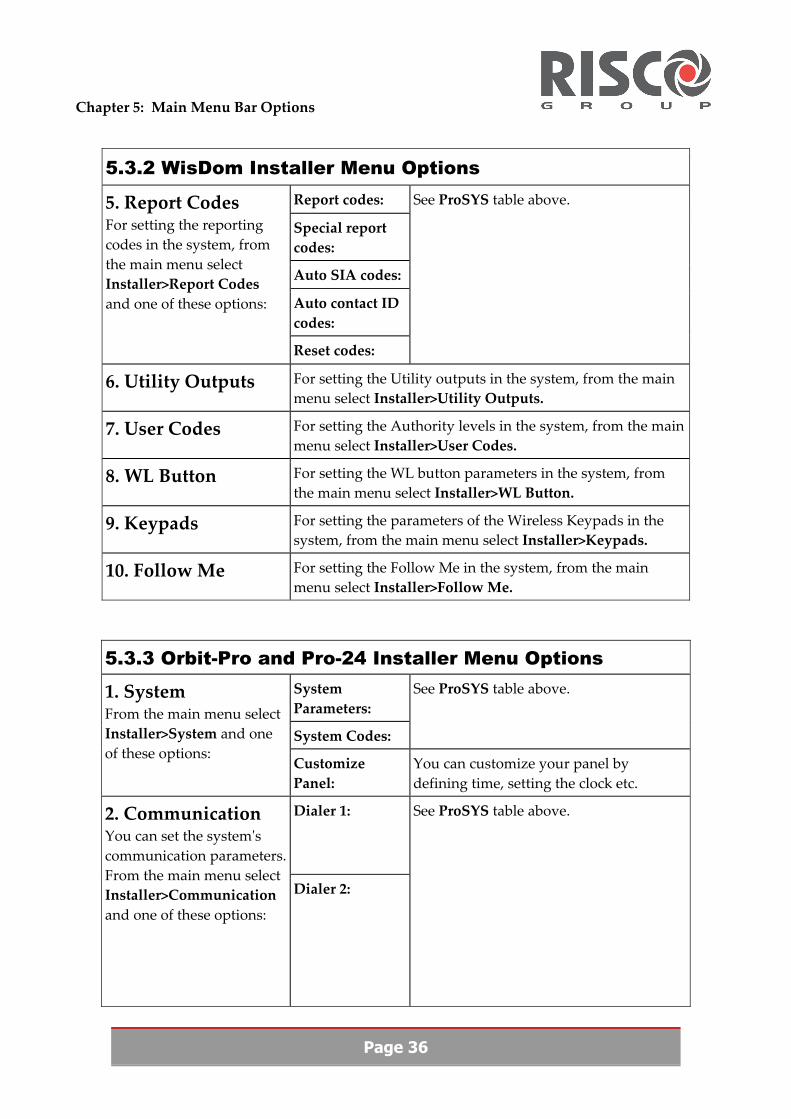
5.3.2 WisDom Installer Menu Options System Parameters:
See ProSYS table above. 1. System From the main menu select Installer>System and one of these options: System Codes: See ProSYS table above.
Dialer 1: See ProSYS table above. 2. Communication You can set the systemʹs communication parameters. From the main menu select Installer>Communication and one of these options:
Dialer 2: See ProSYS table above.
Siren:
GSM:
X10:
You can set the type and configuration of each device in your system.
3. Devices From the main menu select Installer>Devices and one of these options:
Bus test: For performing bus test and reviewing the test result.
Zone parameters:
Zone crossings:
4. Zones For setting zone configurations, from the main menu select Installer>Zones and one of these options:
Soak test:
See ProSYS table above.
Chapter 5: Main Menu Bar Options
Page 36
5.3.2 WisDom Installer Menu Options Report codes:
Special report codes:
Auto SIA codes:
Auto contact ID codes:
5. Report Codes For setting the reporting codes in the system, from the main menu select Installer>Report Codes and one of these options:
Reset codes:
See ProSYS table above.
6. Utility Outputs For setting the Utility outputs in the system, from the main menu select Installer>Utility Outputs.
7. User Codes For setting the Authority levels in the system, from the main menu select Installer>User Codes.
8. WL Button For setting the WL button parameters in the system, from the main menu select Installer>WL Button.
9. Keypads For setting the parameters of the Wireless Keypads in the system, from the main menu select Installer>Keypads.
10. Follow Me For setting the Follow Me in the system, from the main menu select Installer>Follow Me.
5.3.3 Orbit-Pro and Pro-24 Installer Menu Options System Parameters:
System Codes:
See ProSYS table above. 1. System From the main menu select Installer>System and one of these options:
Customize Panel:
You can customize your panel by defining time, setting the clock etc.
Dialer 1: 2. Communication You can set the systemʹs communication parameters. From the main menu select Installer>Communication and one of these options:
Dialer 2:
See ProSYS table above.
Chapter 5: Main Menu Bar Options
Page 37
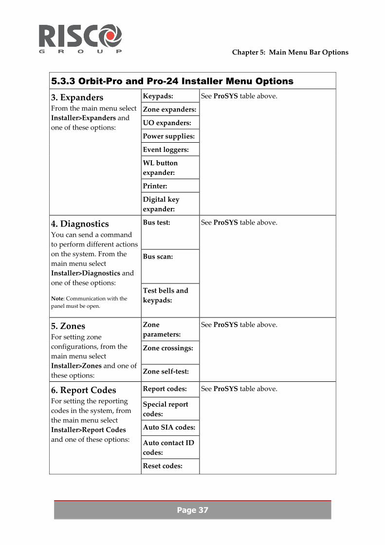
5.3.3 Orbit-Pro and Pro-24 Installer Menu Options Keypads:
Zone expanders:
UO expanders:
Power supplies:
Event loggers:
WL button expander:
Printer:
3. Expanders From the main menu select Installer>Expanders and one of these options:
Digital key expander:
See ProSYS table above.
Bus test:
Bus scan:
4. Diagnostics You can send a command to perform different actions on the system. From the main menu select Installer>Diagnostics and one of these options: Note: Communication with the panel must be open.
Test bells and keypads:
See ProSYS table above.
Zone parameters:
Zone crossings:
5. Zones For setting zone configurations, from the main menu select Installer>Zones and one of these options: Zone self‐test:
See ProSYS table above.
Report codes:
Special report codes:
Auto SIA codes:
Auto contact ID codes:
6. Report Codes For setting the reporting codes in the system, from the main menu select Installer>Report Codes and one of these options:
Reset codes:
See ProSYS table above.

Chapter 5: Main Menu Bar Options
Page 38
5.3.3 Orbit-Pro and Pro-24 Installer Menu Options
7. Utility Outputs For setting the Utility outputs in the system, from the main menu select Installer>Utility Outputs.
See ProSYS table above.
8. User Codes For setting the Authority levels in the system database, from the main menu select Installer>User Codes.
See ProSYS table above.
9. WL Button For setting the WL button in the system, from the main menu select Installer>WL Button.
See ProSYS table above.
5.3.4 Orbit-6 Installer Menu Options
1. System Parameters From the main menu select Installer>System Parameters
You can set the general systemʹs parameters.
2. System Codes From the main menu select Installer>System Codes
You can define installer codes such as Grand Master, Installer, Sub‐Installer as well as allocate Upload/Download Remote Access & ID codes.
Reports codes: 3. Report Codes From the main menu select Installer>Report codes and one of these options:
Update report codes:
See ProSYS table above.
5.3.5 Orbit-14 Installer Menu Options System parameters: 1. System
From the main menu select Installer>System and one of these options:
System codes:
See ProSYS table above.

Chapter 5: Main Menu Bar Options
Page 39
2. Zone Parameters From the main menu select Installer>Zone Parameters
For setting a list of zones, labels, their partition, type, sound etc.
3. Utility Outputs For setting the Utility outputs in the system, from the main menu select Installer>Utility Outputs.
See ProSYS table above.
Reports codes: 3. Report Codes From the main menu select Installer>Report codes and one of these options:
Update report codes:
See ProSYS table above.
5.4 Access Control Menu (for ProSYS only)
The Access Control menu is used to define all parameters that relate to access entry, such as: doors, time definitions, readers, card holders, reports etc. For more information refer to the panelʹs installer manual and the Access Control Module manual.
5.5 End User Menu
Using options from the End User menu you can:
View and save the current system status. Operate the system using the Upload/Download software.
Before using these menu options, select a client and make sure that both the hardware connection and the communication set‐up are in order.
Note: Communication with the panel must be open.

Chapter 5: Main Menu Bar Options
Page 40
5.5.1 ProSYS and WisDom End User Menu Options
1. Status For setting the status of the panel from the main menu select End User>Status and one of these options:
Status display: For displaying the panel and the zones status, and to send partitions and zones commands. Example of a Status Display screen below:
The Status Display screen is divided into sections: a. Zones: The Zone field displays the Zone status, with the codes listed below. Use your mouse to navigate among the zones. Zone codes:
Armed ‐ red Not ready ‐ grey
Alarmed ‐ red and blinking Panic
Bypass
Ready ‐ green
Day Zone Tampered
Trouble ‐ yellow
Unused zone
Fire ‐ red and blinking
Zone not found (for wireless)
Key switch
Low battery (for wireless)
Medical
b. Partitions: The Partitions area in the center of the screen displays the Partitions status (armed, ready or alarmed). To select a Partition, type a Partition number. c. Trouble: The Trouble area on the right of the screen alerts you to problems with the panel accessories. d. Accessories: The Accessories area displays Accessories status. e. Date/Time: To synchronize the time settings on the panel to the time settings of the PC click on the PC>Panel time button and type in the information as follows: Day/month/year/hour/minutes/AM‐PM f. Freeze: Freezes display till it is pressed again. g. No Sound: Deactivates the PC internal speaker after an alarm has been sounded on the panel. h. Save: Saves updated status in the Upload/Download software.

Chapter 5: Main Menu Bar Options
Page 41
5.5.1 ProSYS and WisDom End User Menu Options Saved status display:
To save the current status display.
Set time and date: To set the time and date on the panel. Note: Take the time difference into account if you are in a different time zone.
Next arm/disarm: To set the times for the next arm/disarm of the system.
Scheduler: To set the times for Arm/Disarm, Utility Outputs and user limits.
2. Scheduling For setting the times for the options below, from the main menu select End User>Scheduling and one of these options:
Vacation: For setting the arming/disarming of the system while on vacation.
Access codes: For monitoring panel usersʹ authorization levels and setting their user codes, type in access codes for the Authority levels listed. The Authority levels are generated from the User Codes screen.
Programming: For entering Follow Me phone numbers and Email addresses. For entering the Keypad chimes and buzzer state.
3. User Settings From the main menu select End User>User Settings and one of the options below:
Voice messages: For setting the types of voice messages you wish to be notified of.
Arm partitions: To arm partitions, select the relevant partitions or click All to arm all partitions. Click Arm to activate the partition arming.
Disarm partitions: To disarm partitions, select the relevant partitions or click All to disarm all partitions. Click Dis. to activate the partition disarming.
Activate UO: To activate individual Utility Outputs, type in the number of the Utility Output you require and click the Activate button. Note: Only Utility Outputs that are designated as user activated in the Systems screen are listed here and may be activated using the Activate UO option.
4. User Operations From the main menu select End User>User Operations and one of the options below:
Tamper bypass: Bypassing tamper alarm.

Chapter 5: Main Menu Bar Options
Page 42
5.5.1 ProSYS and WisDom End User Menu Options Test bells and keypads (ProSYS)/ Testing (WisDom):
To send a command to activate and test bells and keypads. When you select this option a dialog box appears informing you if the test was successful or not. Click OK.
5.5.2 Orbit-Pro, Pro-24, Orbit-6, Orbit-14 End User Menu Options
For Orbit‐Pro, Pro‐24, Orbit‐6 and Orbit‐14 panels refer to the panelʹs installer manual to see which of the above options are available to you.
5.6 Comm (Communications) Menu
The Comm menu is used for communication to and from your panel. The options in the Comm menu work automatically when your computer is connected directly to the panel.
5.6.1 Upload Screen
You can upload the current screenʹs parameters from the Control Panel.
To upload data from the panel, to the currently displayed screen only:
1. From the main menu, select Comm>Upload Screen, or from the tool bar, click the Upload
screen icon. The following question appears: ʺAre you sure you want to upload the current screen parameters from the control panel?ʺ
2. Click Yes to upload the current screenʹs parameters from the control panel. 3. The Upload progress bar appears indicating the percentage of the upload completed. 4. A message box appears showing Operation completed successfully. The communication bar at
the bottom of the screen is green.
5.6.2 Upload All
You can upload all parameters from the Control Panel.
To upload all data from the panel for the currently selected client:
1. From the main menu, select Comm>Upload All. The following question appears: ʺAre you sure you want to upload all parameters from the control panel?ʺ
2. Click Yes to upload all parameters from the control panel. 3. The Upload progress bar appears indicating the percentage of the upload completed. 4. A message box appears showing Operation completed successfully.

Chapter 5: Main Menu Bar Options
Page 43
5.6.3 Download Screen
You can download the current screenʹs parameters to the Control Panel.
To download data from the currently displayed screen only, to the panel:
1. From the main menu, select Comm>Download Screen, or from the tool bar, click the Download
screen icon. The following question appears: ʺAre you sure you want to download the current screen parameters to the control panel?ʺ
2. Click Yes to download the current screenʹs parameters to the control panel. 3. The Download progress bar appears indicating the percentage of the download completed. 4. A message box appears showing Operation completed successfully.
5.6.4 Download All
You can download all the client parameters to the Control Panel.
To download all data from the database for the currently selected client, to the panel:
1. From the main menu, select Comm>Download All. The following question appears: ʺAre you sure you want to download all parameters to the control panel?ʺ
2. Click Yes to download all parameters to the control panel. 3. The Download all message box appears showing Writing User Codes – Please wait. 4. The Download progress bar appears indicating the percentage of the download completed. 5. A message box appears showing Operation completed successfully.
5.6.5 Verify Screen
To verify that the data information shown on the screen is identical to the data in the panel, from the main menu.
1. Select the screen that you want to verify.
2. Select Comm>Verify Screen. The fields where there are differences are highlighted in green and automatically toggle between the panel and the data base values.
To replace the database with the panel data (highlighted in green), click Yes. To keep the database as is (highlighted in pink), click No.
5.6.6 Wait for Call
Normally, your modem is not initialized and you are not in a position to receive incoming calls to your Upload/Download system. You can ready your system to receive a call from a client’s panel via the Wait for Call option.

Chapter 5: Main Menu Bar Options
Page 44
To activate Wait for Call:
From the menu bar, select Comm>Wait for Call. A message box appears telling you that the modem is being initialized and that the system is waiting for the call. Of course the call must be initiated from the panel side.
Now the procedure is as follows:
1. The User performs a ʺuser init. Callʺ from the keypad. 2. The Panel calls the Upload/Download, Access and ID codes are being verified. 3. The Upload/Download will automatically select the specific client according to the Panel ID.
5.6.7 Dial to Panel
Use the Dial to Panel option when you wish to connect to a panel via modem and phone line. Remember that your system should be configured for modem communication.
Note: The Dial to Panel option will only be available if a phone number has been entered in the Panel Phone in the Client Information screen.
To dial to panel:
1. From the menu bar select Comm>Dial to Panel, or from the tool bar, click the Dial to Panel icon. The dialing message box appears.
Note: You will be unable to select the Dial to Panel option if you have not entered a telephone number. (In this case the Dial to Panel icon is grey.)
2. If the panel is connected to the same telephone system as an answering machine and the panel is set to answer after more rings than the machine, override the answering machine by pressing the space bar firmly after the first or second ring. Upload/Download redials to the panel.
Note: If you do not press the space bar immediately after the first few rings, the connection will not be successful. In this case the same message box appears. This time do not press the space bar. Message boxes appear indicating connecting to the remote panel.
5.6.8 Hand Over
Your phone line can be used for both conventional phone conversations and communication via modem. You can make a conventional phone call and transfer the call to modem communication using the Hand Over option.
To transfer the call:
1. Transfer the call on the panel side first. (See the Installer manual.)

Chapter 5: Main Menu Bar Options
Page 45
2. From menu bar, select Comm>Hand over. A message box tells you that the modem is initialized and the call is being handed over.
5.5.9 Hang Up
When you no longer need to be on line with the panel, use the Hang Up option to terminate the phone connection.
To hang up:
From the main menu, select Comm>Hang up or press Esc. A message appears sending end of session.
5.6.10 Message to LCD Keypad
You can send a text message to any of the Control Panelʹs partitions.
To send a short message to appear on the LCD keypad connected to the panel:
1. From the main menu select Comm>Message to LCD Keypad. The Send Message to Keypad dialog box appears.
2. In the Message to LCDs field, type a message of up to 16 characters.
3. Click a checkmark into the partition checkboxes for which LCD keypads you want the message to appear.
4. Click the Send button. The message appears on the keypads.
5.7 Event Log Menu
The panel keeps a record of all events that have occurred in its system. This record is the Event Log. You can upload this log and view it, as well as uploading recent events only occurring after your previous upload.
Note: For modem communication, remember to dial to the panel before activating the upload option.
5.7.1 Upload All
To upload the entire Event Log:
From the menu bar, select Event Log>Upload. A message box informs you of the progress of the log upload.

Page 46
5.7.2 Upload Recent
To upload recent events only:
From the menu bar, select Event Log>Upload Recent. A message box informs you of the progress of the log upload.
5.7.3 View
You can view the entire event log that was last generated, from the Main menu bar, select Event Log>View. The Event Log dialog box appears. It has three columns listing event number, time of occurrence and description of the operation:
Num: The number of the event, listed in opposite order. The most recent event is always listed as number one. When recent events are uploaded, the numbering is changed to accommodate this. Time: The time the event took place according to the time settings of the panel. Operation: Description of the event
To print the entire log:
1. Click the Print All button in the lower left corner. The Windows Print dialog box appears. 2. Click OK. The information is sent to the printer.
To print the current page only:
1. Click the Print this page button. 2. Click OK. The information is sent to the printer.
5.7.4 View From File
You can view all previous logs, from the Main menu bar, select Event Log>View From File.
5.8 Help Menu
From the Main menu select Help, the following options appear in the Help menu:
Help Topics On the Web About RISCO Group Upload/Download

Contacting RISCO Group
RISCO Group is committed to customer service and product support. You can contact us through our website www.riscogroup.com or as follows:
United Kingdom Tel:+44‐161‐655‐5500 [email protected] [email protected]
Switzerland Tel: +41‐27‐452‐24‐44 sales‐[email protected] support‐[email protected]
Italy Tel: +39‐02‐66590054 [email protected] [email protected]
USA Toll Free:1‐800‐344‐2025 Tel:+305‐592‐3820 sales‐[email protected] support‐[email protected]
Spain Tel:+34‐91‐490‐2133 sales‐[email protected] support‐[email protected]
Brazil Tel:+55‐11‐3661‐8767 sales‐[email protected] support‐[email protected]
France Tel: +33‐164‐73‐28‐50 sales‐[email protected] support‐[email protected]
China Tel: +86‐21‐52‐39‐0066 sales‐[email protected] support‐[email protected]
Belgium Tel: +32‐2522 7622 sales‐[email protected] support‐[email protected]
Israel Tel: +972‐3963‐7777 [email protected] [email protected]
All rights reserved.
No part of this document may be reproduced in any form without prior written permission from the publisher.
©RISCO Group 6/07 5INUD