unreacted cement content in macro-defect-free composites
TRANSCRIPT

JOURNAL OF MATERIALS SCIENCE 29 (1994) 6445-6452
Unreacted cement content in macro-defect-free composites: impact on processing-structure- property relations
P. G. DESAI* , J. A. LEWIS*, D. P. BENTZ* NSF Science and Technology Center for Advanced Cement Based Materials, *and also Department of Materials Science and Engineering, University of Illinois at Urbana-Champaign, Urban& IL 61801, USA, rand also National Institute of Standards and Technology, Gaithersburg, MD 20899, USA
The effect of unreacted cement content on the processing, structure, and properties of macro-defect-free (MDF) composites fabricated from calcium aluminate cement (CAC), ~-alumina (AI203), and polyvinyl alcohol-acetate (PVAA) has been investigated. Three systems were formed with initial CAC: AI203 ratios of 50:50, 35:65, and 25:75 by volume in their respective formulations. The amount of unreacted cement was reduced from 68.1 vol % which is present in standard (100% CAC) MDF cement, to 14.9 vol% for composites with an initial CAC: AI203 ratio of 25:75, while the hydration product content was reduced from 18.1 vol % to 11.4 vol % for these respective systems. A hard core/soft shell continuum percolation model was used to determine that alumina substitution did not significantly affect the percolative nature of the interphase and bulk polymer regions. However, experiments showed that the reduction in unreacted cement content through AI203 substitution affected both the processing and microstructural features of these composites. The moisture absorption kinetics and flexural strength of composites exposed to 100% relative humidity were also evaluated, and it was found that their moisture sensitivity improved with decreasing unreacted cement content. A hypothesis is presented to explain the role of unreacted cement on the moisture sensitivity of these materials.
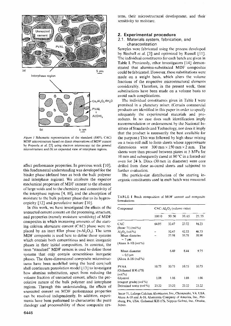
1. I n t r o d u c t i o n Macro-defect-free (MDF) cement was developed by Birchall et al. [13 using a novel processing method. This process consists of mixing a hydraulic cement, a water-soluble polymer, and water under high shear, followed by a low-pressure and low-temperature cur- ing process. When calcium aluminate cement (CAC ~) and polyvinyl alcohol-acetate (PVAN I ) are employed as these constituents, the material exhibits superior mechanical properties [3]. The polymer performs three functions in this material [4] : (1) it acts as a rheological aid, coating individual cement particles, thereby reducing interparticle friction during pro- cessing, (2) it acts as a pore filler, in voids between unreacted cement grains, and (3) it interacts chem- ically with the cement hydration products to form an integral microstructural feature referred to as the in- terphase region [5]. The MDF cement microstructure contains unreacted cement grains, interphase regions which coat individual cement grains, and bulk organic regions (plasticized PVAL ~) as illustrated schematical-
ly in Fig. 1. The interphase regions contain both crystalline (Ca2A12Os.SHeO) and amorphous (AI(OH)3 and PVAL) phases mixed on a nanosized level. The following hydration reaction has been pro- posed by Popoola e t a l . [5], based on their high- resolution electron microscopy (HREM) observations, to account for the presence of these phases
CaAI20, + 5.5H20 --* 0.5CazA12Os"8H20
+ AI(OH) 3 (1)
The conversion of the metastable Ca2A12Os.8H20 phase into the thermodynamically stable Ca3Al206. 6H20 phase is believed to be suppressed by PVAL present in these regions [5-].
The combination of high flexural strength and frac- ture energy as well as low cost makes MDF cements particularly attractive for several applications [4]. However, these properties degrade significantly when MDF cement is exposed to moisture [7-11]. To ad- dress this issue, one must develop a clear understand- ing of how the individual microstructural elements
The abbreviation CAC has been used to denote calcium aluminate cements which contain other phases in addition to the principal CaAI204 phase. IIIUPAC recommended notations used [2]: PVAA = partially hydrolysed polyvinyl alcohol, also known as polyvinyl alcohol-acetate copolymer; PVAL = fully hydrolysed polyvinyl alcohol; PVA has been used here when the term is applicable both PVAA and PVAL. '~ During processing, cement hydration is accompanied by a rise in pH (l 1.0-11.5). This results in hydrolysis of PVAA to form PVAL [6].
0022-2461 �9 1994 Chapman & Hall 6445
tems, their microstructural development, and their sensitivity to moisture.
Interphase region
% |
@ | (b)
| 5 nm
_ _ . . .
�9 Ca2AIzOs.8H20
AI (OH) 3
Figure 1 Schematic representation of the standard (100% CAC) MDF microstructure based on direct observations of MDF cement by Popoola et al. [5] using electron microscopy: (a) the general microstrueture and (b) an expanded view of interphase regions.
affect performance properties. In previous work [10], this fundamental understanding was developed for the binder phase (defined here as both the bulk polymer and interphase regions). We attribute the superior mechanical properties of MDF cement to the absence of large voids and to the chemistry and connectivity of the interphase regions [4, 10], and the absorption of moisture to the bulk polymer phase due to its hygros- copicity [12] and percolative nature [-10].
In this work, we have investigated the effects of the unreacted cement content on the processing, structure, and properties (namely moisture sensitivity) of MDF composites in which increasing amounts of the start- ing calcium aluminate cement (CAC) phase were re- placed by an inert filler phase (~-A1203). The term MDF composite is used here to define those systems which contain both cementitious and inert inorganic phases in their initial composition. In contrast, the term "standard" MDF cement is used to define those systems that only contain cementitious inorganic phases. The three-dimensional composite microstruc- tures have been modelled using the hard core/soft shell continuum percolation model [13] to investigate how alumina substitution, apart from reducing the volume fraction of unreacted cement, affects the per- colative nature of the bulk polymer and interphase regions. Through this understanding, the effects of unreacted cement on MDF performance properties can be resolved independently. In addition, experi- ments have been performed to characterize the paste rheology and processability of these composite sys-
6446
2. Experimental procedure 2.1. Materials system, fabrication, and
characterization Samples were fabricated using the process developed by Birchall et al. [3] and optimized by Russell [11]. The individual constituents for each batch are given in Table I. Previously, other investigators [-14] demon- strated that alumina-substituted MDF composites could be fabricated. However, these substitutions were made on a weight basis, which alters the volume fractions of the respective microstructural elements considerably. Therefore, in the present work, these substitutions have been made on a volume basis to avoid such complications.
The individual constituents given in Table I were premixed in a planetary mixer. (Certain commercial products are identified in this paper in order to specify adequately the experimental materials and pro- cedures. In no case does such identification imply recommendation or endorsement by the National In- stitute of Standards and Technology, nor does it imply that the product is necessarily the best available for the purpose.) This was followed by high shear mixing on a twin-roll mill to form sheets whose approximate dimensions were 300 mmx 150 mmx 2 mm. The sheets were then pressed between plates at 5 MPa for 10 rain and subsequently cured at 80 ~ in a forced-air oven for 24 h. Discs (30 mm in diameter) were core drilled from these as-cured sheets and subjected to further evaluation.
The particle-size distribution of the starting in- organic constituents used in each batch was measured
T A B L E I Batch composition of MDF cement and composite formulations
Component CAC : A120 3 (volume ratio)
100:0 50:50 35:65 25:75
CAC 64.95 32.47 22.72 16.23 (Secar 71) (vol%) AlzO 3 (vol %) - 32.47 42.22 48.73
Mean diameter - 25.98 33.78 38.98 7gm
(Alcoa A-10) (vol %)
Mean diameter 0.5 pm
(Alcoa A-16) (vol %)
6.49 8.44 9.75
PVAA 10.75 10.75 10.75 10.75 (Gohsenol KH-17S) (vol %) Glycerol 1.08 1.08 1.08 1.08 (reagent grade) (vol %) Deionized water (vol %) 23.22 23.22 23.22 23.22
Secar 71, Lafarge Calcium Aluminates, Inc., Chesapeake, VA, USA. Alcoa A-10 and A-16, Aluminum Company of America, Inc., Pitt- sburg, PA, USA. Gohsenol KH-17S, Nippon Gohsei, Inc., Otsaka, Japan.

by a sedimentation technique (X-ray Sedigraph model 5000E, Micromeritics, Inc., Norcross, GA) and the volume per cent distributions were obtained by ac- counting for the density difference between CAC and A1203. Although tile median particle diameters of CAC and A-10 alumina are almost identical, A-10 alumina has a narrower size distribution. Thus, a fine- grained alumina (A-.16) was blended with A-10 alu- mina in a ratio of 1:4 to broaden the A1203 particle- size distribution and improve the processability of these composites. The rheology of pastes formed from the compositions given in Table I was characterized using a Banbury mixer (Haake Rheocord System 90 and Rheomix 600, Fiscons Instruments, Paramus, NJ), the details of which are discussed elsewhere [15].
Selected as-cured MDF composite samples were heated to either 500 or 1000 ~ at a rate of 1 ~ min- i in air. The measured weight loss upon heating to 1000 ~ was used to determine their final composition. This weight loss resulted from the removal of volatile decomposition products produced by PVAA and gly- cerol and by the hydration products (yielding water) present in the interphase regions. The ratio of organic (PVAA and glycerol) to inorganic (CAC and A1203) species should be unaffected during processing. There- fore, after accounting for the loss of organics, the remainder of the weight loss was attributed to loss of water. The final composition of each system given in Table II was then calculated assuming that the sole hydration reaction is given by Equation 1. The com- posite samples heated to 500 ~ were characterized by mercury intrusion porosimetry (Micromeritrics Auto- pore II 9220, Norcross, Ga) to determine how the distribution of binder-filled pores was affected by increasing alumina content. Finally, weight gain and flexural strengths of several representative samples were measured after exposure to 100% relative humidity (r.h.) for various periods of time. Strength measurements (Instron Model 4502, Cannon, MA) were conducted using the biaxial flexural testing method [16].
MDF cements, and to study the percolative nature of the bulk polymer and interphase regions. A complete description of this model is given elsewhere [10]. Some modifications to this model were made in the present work to account for the inert A1203 phase present in the MDF composite microstructures. First, the system size was reduced from its original 150 gm to 50 gm per side cube due to the finer size distribution of the alumina particles (see Fig. 2). The reduction in system size produced systems with approximately 300 000 particles, which were computationally tract- able and nearly identical to the particle content used in previous work [10]. Secondly, two types of hard cores were used in these systems, as shown in Fig. 3: one representing the CAC particles and the other representing the A1203 particles. Hard spherical cores of both types were placed in each system randomly
100
g 80
~- 60
o 40
-5 20 E
0 102
~ " % 25:75 CAC:AI203 '.,~\\\ - - 35:65 CAC:AI203
, ~ 50:50 CAC:AI20 a ~ ~ .. 100:0 CAC:AI203
X Increasing : ~ c o n t e n t
, , . ,
101 10 0 1 Equivalent spherical diameter (pm)
Figure 2 Particle-size distributions of starting inorgamc consti- tuents for each system.
2.2. Model descript ion The hard core/soft shell continuum percolation model has been used previously [10] to model the three- dimensional microstructure of standard (100% CAC)
TABLE II As-cured MDF cement and composite compositions
Component CAC:AIzO 3 (volume ratio)
100:0 50:50 35:65 25:75
Unreacted cement (vol%) 68.1 32.8 21.7 14.9 AI20 3 (vol%) 0 38.9 50.8 59.3 Ca2A12Os.SH20 (vol %) 13.3 10.4 9.75 8.4 AI(OH)3 (vol %) 4.7 3.7 3.45 3.0 Plasticized-PVA (vol %) 13.9 14.2 14.3 14.4
Nonvolatiles (vol %) 70.4 74.5 75.2 76.5 Volatiles (vol %) Plasticized-PVA (vol%) 13.9 14.2 14.3 14.4 H20 (vol %) 15.7 11.3 10.5 9.1
Figure 3 A cross-sectional view of the model microstructure gene- rated for the 25 : 75 CAC:A120 3 system, where the black hard cores represent inert alumina grains, the grey hard cores represent un- reacted cement grains, the light grey soft shells represent interphase regions, and white space represents the bulk polymer regions.
6 4 4 7
using their experimentally determined particle-size distributions. Periodic boundaries were employed to eliminate the edge effects associated with inefficient particle packing in these regions. Three model systems were developed corresponding to initial CAC:AI20 3 ratios of 50: 50, 35:65, and 25:75 by volume. The CAC hard cores were reduced in volume by 11, 16, and 20 vol % in these respective systems to account for their varying extent of hydration (refer to Table II). Finally, soft shells of constant thickness, which re- presented the interphase regions, were added to the CAC hard cores. The inert A1203 hard cores were left unaltered.
The simulated three-dimensional microstructures corresponding to each system (50:50, 35:65, and 25:75 CAC:AI203) were first studied to determine their optimum soft-shell thicknesses [10]. These thick- nesses were obtained by comparing the computed volume fractions of the resulting interphase regions to those obtained experimentally. The composition of these regions was assumed to be the same as deter- mined previously [10]. The microstructures corres- ponding to these "best" shell thicknesses were then evaluated to determine the percolation characteristics of the bulk polymer and interphase regions as de- scribed previously [103.
3. Results and discussion 3.1. Phase composition and distribution
in MDF composites The compositions of the as-cured MDF composite samples are given in Table II. For comparison, the composition of standard MDF cement is also in- cluded. An increase in the amount of alumina substi- tution resulted in a decrease in the unreacted cement content in the as-cured composites from 68.1 vol % to 14.9 vol%. However, as expected, their hydration product content did not decrease to the same extent due to the variation in their initial compositions (e.g. water:cement ratio). Furthermore, the amount of ce- ment hydrated in these composites increased from 7 vol % for standard MDF cement [10] to 11, 16, and 20 vol % for initial CAC: A120 3 ratios of 50: 50, 35 : 65, and 25:75 by volume, respectively. The hydrated ce- ment content was calculated by taking a ratio of the volume fraction of reacted cement to the volume fraction of the initial cement in these systems, Con- sequently, one would expect the average thickness of the interphase regions to vary in these samples.
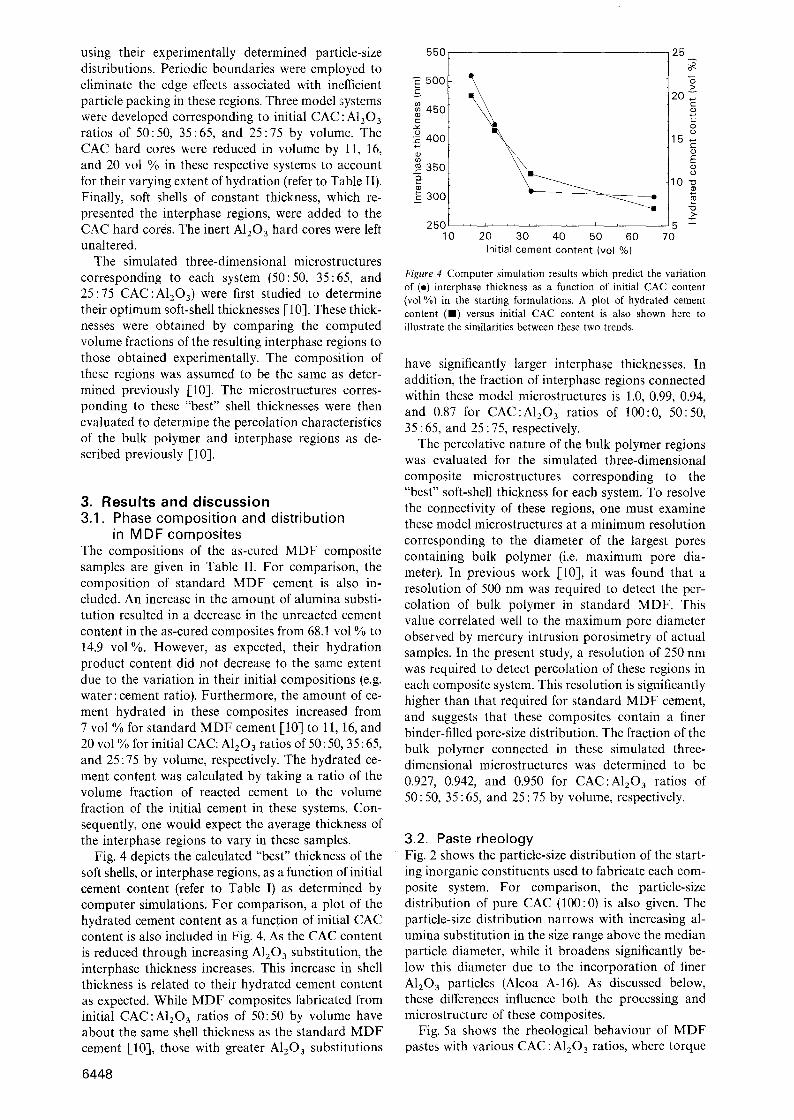
Fig. 4 depicts the calculated "best" thickness of the soft shells, or interphase regions, as a function of initial cement content (refer to Table I) as determined by computer simulations. For comparison, a plot of the hydrated cement content as a function of initial CAC content is also included in Fig. 4. As the CAC content is reduced through increasing A120 3 substitution, the interphase thickness increases. This increase in shell thickness is related to their hydrated cement content as expected. While MDF composites fabricated from initial CAC :A1203 ratios of 50:50 by volume have about the same shell thickness as the standard MDF cement [10], those with greater A120 a substitutions
6448
c
(D
c
o IE
550
500
45O
400
350
300
250 10
, , i , , , , , i , , i , ,
2O 30 40 50 60 Initial cement content (vol %)
25
>
20 c
E o o
1 5 ~
E
0 " o
Z3 > .
5 3: 70
Figure 4 Computer simulation results which predict the variation of (o) interphase thickness as a function of initial CAC content (vol%) in the starting formulations. A plot of hydrated cement content ([]) versus initial CAC content is also shown here to illustrate the similarities between these two trends,
have significantly larger interphase thicknesses. In addition, the fraction of interphase regions connected within these model microstructures is 1.0, 0.99, 0.94, and 0.87 for CAC:A120 3 ratios of 100:0, 50:50, 35 : 65, and 25 : 75, respectively.
The percolative nature of the bulk polymer regions was evaluated for the simulated three-dimensional composite microstructures corresponding to the "best" soft-shell thickness for each system. To resolve the connectivity of these regions, one must examine these model microstructures at a minimum resolution corresponding to the diameter of the largest pores containing bulk polymer (i.e. maximum pore dia- meter). In previous work [10], it was found that a resolution of 500 nm was required to detect the per- colation of bulk polymer in standard MDF. This value correlated well to the maximum pore diameter observed by mercury intrusion porosimetry of actual samples. In the present study, a resolution of 250 nm was required to detect percolation of these regions in each composite system. This resolution is significantly higher than that required for standard MDF cement, and suggests that these composites contain a finer binder-filled pore-size distribution. The fraction of the bulk polymer connected in these simulated three- dimensional microstructures was determined to be 0.927, 0.942, and 0.950 for CAC:A120 3 ratios of 50 : 50, 35 : 65, and 25 : 75 by volume, respectively.
3.2. Pas te rheo logy Fig. 2 shows the particle-size distribution of the start- ing inorganic constituents used to fabricate each com- posite system. For comparison, the particle-size distribution of pure CAC (100:0) is also given. The particle-size distribution narrows with increasing al- umina substitution in the size range above the median particle diameter, while it broadens significantly be- low this diameter due to the incorporation of finer A1103 particles (Alcoa A-16). As. discussed below, these differences influence both the processing and microstructure of these composites.
Fig. 5a shows the rheological behaviour of MDF pastes with various CAC:A1203 ratios, where torque

40
35
3O
"E25 z
20 G
~_15
10
Processing_ - window >
1:75 CAC:AI203
35:65 CAC:AI203
50:50 CAC:AI203
~'[ I , [ I ]]I 0 r
0 5 10 (a) Time (min)
Matrix , (
degradation
15 20
which are a consequence of the increased torque values.
3.3. Pore structure of MDF composites Mercury intrusion porosimetry (MIP) was used to analyse the pore development of representative MDF composite samples heat treated to 500~ Fig. 6 shows the incremental porosity as a function of pore diameter for these composites. To account for the differences in sample density resulting from their dif- fering AlzO3 content, we converted the raw MIP data to volume of porosity intruded, using Equation 2 below.
12 , , ~ . . . . , 2tandar d Processing window
~ '~ ' /'I' ~ MDF c e m e n t
8 ~- degradation- g J z : ~t i o b - 4
j, 2~ i i n n1 IV
O �9 ' '
0 5 10 15 20 25
(b) Time (min)
Figure 5 The rheological behaviour, as given by torque as a func- tion of time, for pastes formed from: (a) the M D F composite systems and (b) standard M D F cement processed at 100 r.p.m.
is plotted as a function of time. To aid our interpreta- tion, we compared these observations to those re- ported by McHugh and Tan [15] on standard MDF pastes shown in Fig. 5b. The rheological behaviour of these pastes is complex and can be divided into four regions. Regions I and II, which are readily identifi- able for standard MDF pastes, are combined into one broad peak in the torques curves obtained on the CAC:A1203 composite pastes. The magnitude of this broad peak increases substantially with increasing alumina content, which we believe results partly from an increase in the interparticle friction. Furthermore, region III also differs; significantly for these pastes as compared to standard MDF cement. McHugh and Tan [15] hypothesized that the slow rise in torque observed in this region resulted from the development of cross-linked network structure in the paste. Beyond this second torque maxima, the standard paste breaks down into a friable mass (designated as region IV). Although no rise in torque was observed for our pastes, beyond the plateau in region III these pastes also broke down (region IV). It is possible that the overall torque increase, resulting from the alumina content in these pastes, has masked these subtle fea- tures in region III. Alternatively, the extent of network formation may be less in our systems as a result of the reduction in hydration product content. Finally, we believe the narrower processing windows observed in our systems result from higher paste temperatures,
•Tin t
where Pint is the amount of porosity intruded (%) at a given pressure, Vint is the volume of mercury intruded (cm 3 g- 1) at a given pressure, and Papp is the apparent density (gcm- 3) measured by MIP for a given sample. Note, the apparent density does not include pore volume for closed pores or very fine pores ( < 3 nm diameter).
The bimodal pore-size distributions shown in Fig. 6 develop upon the removal of volatile constituents from these samples. The larger pores are associated with the removal of bulk polymer, whereas the finer pores are associated with the removal of matter from the interphase regions, as illustrated for standard MDF [10]. A characteristic pore size, defined as the maximum of the incremental intrusion curve, was determined for the porosity that develops for each of these binder regions. The characteristic pore size for the larger pores decreases from approximately 170 nm to 80 nm with increasing alumina substitutions, which is expected based on their respective particle-size dis- tributions. However, the characteristic size of the smaller pores ( g 15 nm) was found to be independent of alumina substitution. This, too, is expected, because alumina is inert with respect to hydration.
The maximum pore diameter, D . . . . of these com- posites was determined by MIP to be approximately 200-225 nm. The onset of intrusion is much lower
2.5
~ 2 , 0 v
1.5 o t~
E 1.o E P ~o.5
0.0
25:75 CAC:AI203
~[ I 50:50 I t ~, CAC:AI203
10 -2 1 0 -1
Pore diameter (/Jm)
Figure 6 Incremental porosity as a function of pore diameter for MDF composites heat treated to 500 ~ at a rate of i ~ min- 1
6449
than that observed for standard MDF cement (Dmax, ,~ 510 nm) [10], and is in good agreement with the values predicted by computer modelling ( 250 nm). This result supports the use of this modified version of the hard core/soft shell continuum percola- tion model to simulate the three-dimensional micro- structure of these composites.
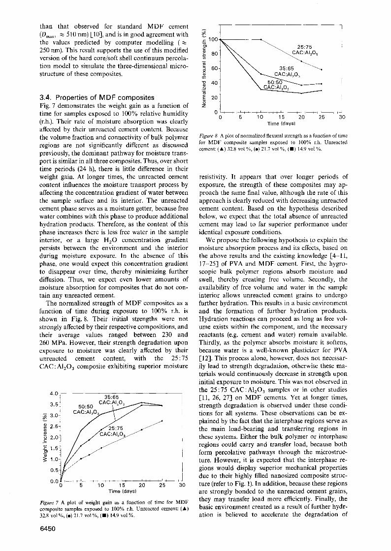
3.4. Properties of MDF composites Fig. 7 demonstrates the weight gain as a function of time for samples exposed to 100% relative humidity (r.h.). Their rate of moisture absorption was clearly affected by their unreacted cement content. Because the volume fraction and connectivity of bulk polymer regions are not significantly different as discussed previously, the dominant pathway for moisture trans- port is similar in all three composites. Thus, over short time periods (24 h), there is little difference in their weight gain. At longer times, the unreacted cement content influences the moisture transport process by affecting the concentration gradient of water between the sample surface and its interior. The unreacted cement phase serves as a moisture getter, because free water combines with this phase to produce additional hydration products. Therefore, as the content of this phase increases there is less free water in the sample interior, or a large H20 concentration gradient persists between the environment and the interior during moisture exposure. In the absence of this phase, one would expect this concentration gradient to disappear over time, thereby minimizing further diffusion. Thus, we expect even lower amounts of moisture absorption for composites that do not con- tain any unreacted cement.
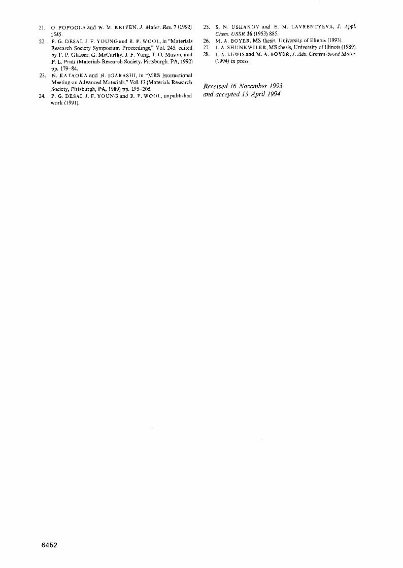
The normalized strength of MDF composites as a function of time during exposure to 100% r.h. is shown in Fig. 8. Their initial strengths were not strongly affected by their respective compositions, and their average values ranged between 230 and 260 MPa. However, their strength degradation upon exposure to moisture was clearly affected by their unreacted cement content, with the 25:75 CAC:A120 3 composite exhibiting superior moisture
4'01 35:65 CAC:AI203 3.5 50:50 / _ . ~ / ~
o~ 3'01 C A C ~
2.0
1.o
0.5
0.0 0 5 10 15 20 25 30 Time (days)
Figure 7 A plot of weight gain as a function of time for MDF composite samples exposed to 100% r.h. Unreacted cement: (A) 32.8 vol %, (e) 21.7 vol %, (11) 14.9 vol %.
A
v
t -
t -
X
" 1 3
.3
0 z
80 \ \ 60 ~ ~ 35:65
L . . . . . . 2 " 3
20~
0 i i i I I i i ~ i I ; L I ~ i I I I I I ; - I I I , ~
0 5 10 15 20 25 30 Time (days)
Figure 8 A plot of normalized flexural strength as a function of time for MDF composite samples exposed to 100% r.h. Unreacted cement: (Ik) 32.8 vol %, (e) 21.7 vol %, (HI) 14.9 vol %.
resistivity. It appears that over longer periods of exposure, the strength of these composites may ap- proach the same final value, although the rate of this approach is clearly reduced with decreasing unreacted cement content. Based on the hypothesis described below, we expect that the total absence of unreacted cement may lead to far superior performance under identical exposure conditions.
We propose the following hypothesis to explain the moisture absorption process and its effects, based on the above results and the existing knowledge [4-11, 17-25] of PVA and MDF. cement. First, the hygro- scopic bulk polymer regions absorb moisture and swell, thereby creating free volume. Secondly, the availability of free volume and water in the sample interior allows unreacted cement grains to undergo further hydration. This results in a basic environment and the formation of further hydration products. Hydration reactions can proceed as long as free vol- ume exists within the component, and the necessary reactants (e.g. cement and water) remain available. Thirdly, as the polymer absorbs moisture it softens, because water is a well-known plasticizer for PVA [12]. This process alone, however, does not necessar- ily lead to strength degradation, otherwise these ma- terials would continuously decrease in strength upon initial exposure to moisture. This was not observed in the 25:75 CAC:A1203 samples or in other studies [11, 26, 27] on MDF cements. Yet at longer times, strength degradation is observed under these condi- tions for all systems. These observations can be ex- plained by the fact that the interphase regions serve as the main load-bearing and transferring regions in these systems. Either the bulk polymer or interphase regions could carry and transfer load, because both form percolative pathways through the microstruc- ture. However, it is expected that the interphase re- gions would display superior mechanical properties due to their highly filled nanosized composite struc- ture (refer to Fig. 1). In addition, because these regions are strongly bonded to the unreacted cement grains, they may transfer load more efficiently. Finally, the basic environment created as a result of further hydr- ation is believed to accelerate the degradation of
6450

polymer in both regions leading to the observed strength loss of these MDF materials.
In this study, the maximum amount of AI203 that could be substituted for CAC was 75 vol %, while still yielding a processable paste. Although this produces a final MDF composite with much lower unreacted cement contents than observed in standard MDF materials, their cement content is still fairly high relative to the total amount of moisture absorbed during exposure to 100% r.h. as calculated below. The absorbed water could react with the CAC grains to form either the CazAlzOs'8H20 phase according to Equation 1 or the thermodynamically stable Ca3AI206.6H20 phase as given by the reaction below
3CaAI204 + 12HzO ~ Ca3AlzO6"6HzO
+ 4Al(OH)3 (3)
The amount of moisture absorption required to con- sume completely the CaAI204 phase present in each composite can be calculated for either reaction, Equa- tion 1 or Equation 3. The unreacted cement grains contain approximately 48 wt % CaA1/O 4 [i1]; thus, the required amount of absorbed water is 4.2, 6.3, and 9.8 wt % according to Equation 1 and 3.0, 4.5, and 7.2 wt % according to Equation 3 for composites corres- ponding to CAC : A1203 ratios of 25 : 75, 35 : 65, and 50:50 by volume, respectively. Hence, even for these systems, a significant amount of water needs to be absorbed before they approach equilibrium. These results clearly serve as a guideline for future design of MDF materials. Although this study is the first to demonstrate the deleterious effects of unreacted ce- ment content on the moisture sensitivity of MDF materials, it also illustrates that much lower contents are required to successfully improve their per- formance.
In summary, two processing strategies have emer- ged from our work to improve the moisture sensitivity of MDF cements and composite systems through microstructural design. First, one must minimize the unreacted cement content present within the three- dimensional microstructure, while maximizing the in- terphase region connectivity and content. This can be achieved in part by producing a finer, more evenly distributed cement phase in the starting materials system which is completely consumed during fabric- ation. Secondly, one must modify either the accessibil- ity (or connectivity) of the bulk polymer regions, or their hygroscopic nature. Its accessibility can be mini- mized by decreasing the bulk polymer to interphase region ratio, whereas its affinity for water can be altered through chemical modification as suggested previously [11, 23, 26, 283.
4. Conclusions The effects of reducing the unreacted cement content on processing, structure, and moisture sensitivity of CAC-PVAA-based MDF composites have been in- vestigated through both computer simulations and experiments. A modified hard core/soft shell con- tinuum percolation model was used to successfully
model the three-dimensional alumina-substituted MDF composite microstructures. It was shown that both the bulk polymer and interphase regions form percolative pathways in these microstructures. Fur- thermore, the accessibility of the bulk polymer phase was shown to remain unaltered, while the thickness of the interphase regions was found to increase as their cement content decreased. According to our hypoth- esis, the bulk polymer provides a pathway for water absorption and transport, but this process alone is not responsible for the observed strength loss during moisture exposure. We have proposed that their strength loss is affected by further hydration of un- reacted cement grains, which leads to an accelerated deterioration of the performance properties of MDF materials. In addition, these results suggest that the keys to optimizing the microstructural design of MDF cements are to minimize their unreacted cement con- tent and to eliminate their pathway for moisture transport.
Acknowledgements The authors thank Professor J. F. Young and Ms A. L. Ogden for useful discussions, and Mr L. S. Tan for assistance with the rheological measurements. This work was supported by the National Science Founda- tion through the Science and Technology Center for Advanced Cement-Based Materials (ACBM) under Grant DMR 91-2002.
References 1, J. D. BIRCHALL, A. J. HOWARD and K. KENDALL,
Nature 289 (1981) 388. 2, Anon, Pure Appl. Chem. 18 (1969) 583. 3. J .D . BIRCHALL, A. J. HOWARD, and K. KENDALL, US
Pat. 4410 366 (1983). 4. S. R. TAN, A. J. HOWARD and J. D. BIRCHALL, Phil.
Trans. R. Soc. Lond. A322 (1987) 479. 5. O. POPOOLA, W. M. KRIVEN and J. F. YOUNG, J. Am.
Ceram. Soc. 74 (1991) 1928, 6. P . G . DESAI, MS thesis, University of Illinois (1992). 7. C .M. CANNON and G. W. GROVES, J. Mater. Sei. 21 (1986)
4009. 8. C.S . POON, L. E. WASSALL and G. W. GROVES, Mater.
Sci. Technol, (1988) 993. 9. N.B. EDEN and J. E. BAILEY, ibid. (1988) 301.
10. J . A . LEWIS, M. A. BOYER and D. P. BENTZ, J. Am. Ceram. Soc. 77 (3) (1993) 11.
11. P . P . RUSSELL, MS thesis, University of Illinois (1991). 12. K. TOYOSHIMA, in "Polyvinyl Alcohol: Properties and
Applications" edited by C. A. Finch (Wiley-Interscience, New York, 1973) pp. 339-90.
13. I. BALBERG and S. T O R Q U A T O , Phys. Rev. A 35 (1987) 5174.
14. R .A. DESAI, MS thesis, University of Illinois (1990). 15. A.J . M c H U G H and L. S. TAN, J. Adv. Cement-Based Mater.
1 (1993) 2, 16. J .B. WACHTMAN, W. CAPPS and J. MANDEL, J. Mater.
7 (1972) 188. 17. W. SINCLAIR and G. W. GROVES, J. Mater. Sci. 20 (1985)
2846. 18. S. A. RODGER, S. A. BROOKS, W. SINCLAIR, G. W.
GROVES and D. D. DOUBLE, ibid. 20 (1985) 2853. 19. R . N . EDMONDS and A. J. MAJUMDAR, ibid. 24 (1989)
3813. 20. O. POPOOLA, W. M. KRIVEN and J. F. YOUNG, Ultra-
microscopy 37 (1991) 318.
6451
21. O. POPOOLA and W. M. KRIVEN, J. Mater. Res. 7 (1992) 1545.
22. P.G. DESAI, J. F. YOUNG and R. P. WOOL, in "Materials Research Society Symposium Proceedings," VoL 245, edited by F. P. Glasser, G. McCarthy, J. F. Yang, T. O. Mason, and P. L. Pratt (Materials Research Society, Pittsburgh, PA, 1992) pp. 179-84.
23. N. KATAOKA and H. IGARASHI, in "MRS International Meeting on Advanced Materials," Vol. I3 (Materials Research Society, Pittsburgh, PA, 1989) pp. 195-205.
24. P.G. DESAI, J. F. YOUNG and R. P. WOOL, unpublished work (1991).
25. S. N. USHAKOV and E. M. LAVRENTYEVA, J. Appl. Chem. USSR 26 (1953) 885.
26. M.A. BOYER, MS thesis, University of Illinois (1993). 27. J.A. SHUNKWILER, MS thesis, University of Illinois (1989). 28. J.A. LEWIS and M. A. BOYER, J. Adv. Cement-based Mater.
(1994) in press,
Received 16 November 1993 and accepted 13 April 1994
6452