unmanned aircraft design - morganclaypoolpublishers.com · system design. the design of manned...
TRANSCRIPT

Unmanned Aircraft DesignA Review of Fundamentals
ER/MP Gray Eagle: Enhanced MQ-1C Predator


iii
Synthesis Lectures on Mechanical Engineering
Synthesis Lectures on Mechanical Engineering series publishes 60–150 page publications pertain-ing to this diverse discipline of mechanical engineering. The series presents Lectures written for an audience of researchers, industry engineers, undergraduate and graduate students. Additional Synthesis series will be developed covering key areas within mechanical engineering.
Introduction to Refrigeration and Air Conditioning Systems: Theory and ApplicationsAllan KirkpatrickSeptember 2017
Resistance Spot Welding: Fundamentals and Applications for the Automotive IndustryMenachem Kimchi and David H. PhillipsSeptember 2017
Unmanned Aircraft Design: Review of FundamentalsMohammad SadraeySeptember 2017
MEMS Barometers Towards Vertical Position Detection: Background Theory, System Prototyping, and Measurement AnalysisDimosthenis E. Bolankis2017
Vehicle Suspension System Technology and DesignAmir Khajepour and Avesta GoodarziApril 2017
Engineering Finite Element AnalysisRamana PidapartiMay 2017

Copyright © 2017 by Morgan & Claypool
All rights reserved. No part of this publication may be reproduced, stored in a retrieval system, or transmitted inany form or by any means—electronic, mechanical, photocopy, recording, or any other except for brief quota-tions in printed reviews, without the prior permission of the publisher.
Unmanned Aircraft Design: A Review of Fundamentals Mohammad Sadraeywww.morganclaypool.com
ISBN: 9781681731681 printISBN: 9781681731698 ebook
DOI 10.2200/S00789ED1V01Y201707MEC004
A Publication in the Morgan & Claypool Publishers seriesSYNTHESIS LECTURES ON MECHANICAL ENGINEERING, #04
Series ISSN: 2573-3168 Print 2573-3176 Electronic

Unmanned Aircraft DesignA Review of FundamentalsMohammad H. SadraeySouthern New Hampshire University
SYNTHESIS LECTURES ON MECHANICAL ENGINEERING #04
M&C MORGAN & CLAYPOOL PUBLISHERS
vi
ABSTRACTThis book provides fundamental principles, design procedures, and design tools for unmanned aerial vehicles (UAVs) with three sections focusing on vehicle design, autopilot design, and ground system design. The design of manned aircraft and the design of UAVs have some similarities and some differences. They include the design process, constraints (e.g., g-load, pressurization), and UAV main components (autopilot, ground station, communication, sensors, and payload). A UAV designer must be aware of the latest UAV developments; current technologies; know lessons learned from past failures; and they should appreciate the breadth of UAV design options.
The contribution of unmanned aircraft continues to expand every day and over 20 countries are developing and employing UAVs for both military and scientific purposes. A UAV system is much more than a reusable air vehicle or vehicles. UAVs are air vehicles, they fly like airplanes and operate in an airplane environment. They are designed like air vehicles; they have to meet flight critical air vehicle requirements. A designer needs to know how to integrate complex, multi-disci-plinary systems, and to understand the environment, the requirements and the design challenges and this book is an excellent overview of the fundamentals from an engineering perspective.
This book is meant to meet the needs of newcomers into the world of UAVs. The materials are intended to provide enough information in each area and illustrate how they all play together to support the design of a complete UAV. Therefore, this book can be used both as a reference for engineers entering the field or as a supplementary text for a UAV design course to provide sys-tem-level context for each specialized topic.
KEYWORDSunmanned aerial vehicles, design, automatic flight control system, autopilot, drone, remotely pi-loted vehicle

vii
Contents Preface . . . . . . . . . . . . . . . . . . . . . . . . . . . . . . . . . . . . . . . . . . . . . . . . . . . . . . . . . . . . xiii
Part I . . . . . . . . . . . . . . . . . . . . . . . . . . . . . . . . . . . . . . . . . . . . xv
1 Design Fundamentals . . . . . . . . . . . . . . . . . . . . . . . . . . . . . . . . . . . . . . . . . . . . . . . . 11.1 Introduction . . . . . . . . . . . . . . . . . . . . . . . . . . . . . . . . . . . . . . . . . . . . . . . . . . . 11.2 UAV Classifications . . . . . . . . . . . . . . . . . . . . . . . . . . . . . . . . . . . . . . . . . . . . . 31.3 Design Project Planning . . . . . . . . . . . . . . . . . . . . . . . . . . . . . . . . . . . . . . . . . 61.4 Decision Making . . . . . . . . . . . . . . . . . . . . . . . . . . . . . . . . . . . . . . . . . . . . . . . 61.5 Design Criteria, Objectives, and Priorities . . . . . . . . . . . . . . . . . . . . . . . . . . . . 71.6 Feasibility Analysis . . . . . . . . . . . . . . . . . . . . . . . . . . . . . . . . . . . . . . . . . . . . . . 91.7 Design Groups . . . . . . . . . . . . . . . . . . . . . . . . . . . . . . . . . . . . . . . . . . . . . . . . 101.8 Design Process . . . . . . . . . . . . . . . . . . . . . . . . . . . . . . . . . . . . . . . . . . . . . . . . 111.9 Systems Engineering Approach . . . . . . . . . . . . . . . . . . . . . . . . . . . . . . . . . . . 121.10 Conceptual Design . . . . . . . . . . . . . . . . . . . . . . . . . . . . . . . . . . . . . . . . . . . . . 151.11 Preliminary Design . . . . . . . . . . . . . . . . . . . . . . . . . . . . . . . . . . . . . . . . . . . . 201.12 Detail Design . . . . . . . . . . . . . . . . . . . . . . . . . . . . . . . . . . . . . . . . . . . . . . . . . 211.13 Design Review, Evaluation, and Feedback . . . . . . . . . . . . . . . . . . . . . . . . . . . 231.14 Questions . . . . . . . . . . . . . . . . . . . . . . . . . . . . . . . . . . . . . . . . . . . . . . . . . . . . 24
2 Design Disciplines . . . . . . . . . . . . . . . . . . . . . . . . . . . . . . . . . . . . . . . . . . . . . . . . . . 272.1 Introduction . . . . . . . . . . . . . . . . . . . . . . . . . . . . . . . . . . . . . . . . . . . . . . . . . . 272.2 Aerodynamic Design . . . . . . . . . . . . . . . . . . . . . . . . . . . . . . . . . . . . . . . . . . . 282.3 Structural Design . . . . . . . . . . . . . . . . . . . . . . . . . . . . . . . . . . . . . . . . . . . . . . 302.4 Propulsion System Design . . . . . . . . . . . . . . . . . . . . . . . . . . . . . . . . . . . . . . . 322.5 Landing Gear Design . . . . . . . . . . . . . . . . . . . . . . . . . . . . . . . . . . . . . . . . . . 332.6 Mechanical/Power Transmission Systems Design . . . . . . . . . . . . . . . . . . . . . 352.7 Control Surfaces Design . . . . . . . . . . . . . . . . . . . . . . . . . . . . . . . . . . . . . . . . 372.8 Questions . . . . . . . . . . . . . . . . . . . . . . . . . . . . . . . . . . . . . . . . . . . . . . . . . . . . 44
Part II . . . . . . . . . . . . . . . . . . . . . . . . . . . . . . . . . . . . . . . . . . . . . . . . . . . . . . . . . . . . . . . . . 47
3 Fundamentals of Autopilot . . . . . . . . . . . . . . . . . . . . . . . . . . . . . . . . . . . . . . . . . . . 493.1 Introduction . . . . . . . . . . . . . . . . . . . . . . . . . . . . . . . . . . . . . . . . . . . . . . . . . . 49

viii
3.2 Primary Subsystems of an Autopilot . . . . . . . . . . . . . . . . . . . . . . . . . . . . . . 493.3 Dynamic Modeling . . . . . . . . . . . . . . . . . . . . . . . . . . . . . . . . . . . . . . . . . . . . 503.4 UAV Dynamics . . . . . . . . . . . . . . . . . . . . . . . . . . . . . . . . . . . . . . . . . . . . . . . 533.5 Aerodynamic Forces and Moments . . . . . . . . . . . . . . . . . . . . . . . . . . . . . . . . 543.6 Stability and Control Derivatives . . . . . . . . . . . . . . . . . . . . . . . . . . . . . . . . . . 563.7 Transfer Function . . . . . . . . . . . . . . . . . . . . . . . . . . . . . . . . . . . . . . . . . . . . . . 573.8 State-Space Model . . . . . . . . . . . . . . . . . . . . . . . . . . . . . . . . . . . . . . . . . . . . . 583.9 Linearization . . . . . . . . . . . . . . . . . . . . . . . . . . . . . . . . . . . . . . . . . . . . . . . . . 583.10 Autopilot Design Process . . . . . . . . . . . . . . . . . . . . . . . . . . . . . . . . . . . . . . . . 603.11 Questions . . . . . . . . . . . . . . . . . . . . . . . . . . . . . . . . . . . . . . . . . . . . . . . . . . . . 61
4 Control System Design . . . . . . . . . . . . . . . . . . . . . . . . . . . . . . . . . . . . . . . . . . . . . . 634.1 Introduction . . . . . . . . . . . . . . . . . . . . . . . . . . . . . . . . . . . . . . . . . . . . . . . . . . 634.2 Fundamentals of Control Systems . . . . . . . . . . . . . . . . . . . . . . . . . . . . . . . . . 644.3 UAV Control Architecture . . . . . . . . . . . . . . . . . . . . . . . . . . . . . . . . . . . . . . . 67
4.3.1 Control Categories . . . . . . . . . . . . . . . . . . . . . . . . . . . . . . . . . . . . . . 674.3.2 Cruise Control . . . . . . . . . . . . . . . . . . . . . . . . . . . . . . . . . . . . . . . . . 69
4.4 Flight Control Requirements . . . . . . . . . . . . . . . . . . . . . . . . . . . . . . . . . . . . . 704.4.1 Longitudinal Control Requirements . . . . . . . . . . . . . . . . . . . . . . . . 704.4.2 Roll Control Requirements . . . . . . . . . . . . . . . . . . . . . . . . . . . . . . . . 724.4.3 Directional Control Requirements . . . . . . . . . . . . . . . . . . . . . . . . . . 72
4.5 PID Controller . . . . . . . . . . . . . . . . . . . . . . . . . . . . . . . . . . . . . . . . . . . . . . . 734.6 Optimal Control-Linear Quadratic Regulator (LQR) . . . . . . . . . . . . . . . . . 734.7 Robust Control . . . . . . . . . . . . . . . . . . . . . . . . . . . . . . . . . . . . . . . . . . . . . . . 744.8 Digital Control . . . . . . . . . . . . . . . . . . . . . . . . . . . . . . . . . . . . . . . . . . . . . . . 754.9 Stability Augmentation . . . . . . . . . . . . . . . . . . . . . . . . . . . . . . . . . . . . . . . . . 764.10 Autonomy . . . . . . . . . . . . . . . . . . . . . . . . . . . . . . . . . . . . . . . . . . . . . . . . . . . 79
4.10.1 Classification . . . . . . . . . . . . . . . . . . . . . . . . . . . . . . . . . . . . . . . . . . . 794.10.2 Detect (i.e., Sense)-and-Avoid . . . . . . . . . . . . . . . . . . . . . . . . . . . . . 814.10.3 Automated Recovery . . . . . . . . . . . . . . . . . . . . . . . . . . . . . . . . . . . . . 814.10.4 Fault Monitoring . . . . . . . . . . . . . . . . . . . . . . . . . . . . . . . . . . . . . . . 814.10.5 Intelligent Flight Planning . . . . . . . . . . . . . . . . . . . . . . . . . . . . . . . . 824.10.6 Manned-Unmanned Teaming . . . . . . . . . . . . . . . . . . . . . . . . . . . . . 82
4.11 Control System Design Process . . . . . . . . . . . . . . . . . . . . . . . . . . . . . . . . . . . 834.12 Questions . . . . . . . . . . . . . . . . . . . . . . . . . . . . . . . . . . . . . . . . . . . . . . . . . . . . 864.13 Problems . . . . . . . . . . . . . . . . . . . . . . . . . . . . . . . . . . . . . . . . . . . . . . . . . . . . 87
5 Navigation System Design . . . . . . . . . . . . . . . . . . . . . . . . . . . . . . . . . . . . . . . . . . . . 91

ix
5.1 Introduction . . . . . . . . . . . . . . . . . . . . . . . . . . . . . . . . . . . . . . . . . . . . . . . . . . 915.2 Coordinate Systems . . . . . . . . . . . . . . . . . . . . . . . . . . . . . . . . . . . . . . . . . . . . 925.3 Inertial Navigation System . . . . . . . . . . . . . . . . . . . . . . . . . . . . . . . . . . . . . . 925.4 Global Positioning System . . . . . . . . . . . . . . . . . . . . . . . . . . . . . . . . . . . . . . 955.5 Position Fixing Navigation . . . . . . . . . . . . . . . . . . . . . . . . . . . . . . . . . . . . . . 96
5.5.1 Map Reading . . . . . . . . . . . . . . . . . . . . . . . . . . . . . . . . . . . . . . . . . . 965.5.2 Celestial Navigation . . . . . . . . . . . . . . . . . . . . . . . . . . . . . . . . . . . . . 97
5.6 Inertial Navigation Sensors . . . . . . . . . . . . . . . . . . . . . . . . . . . . . . . . . . . . . . 975.6.1 Accelerometer . . . . . . . . . . . . . . . . . . . . . . . . . . . . . . . . . . . . . . . . . . 985.6.2 Gyroscope . . . . . . . . . . . . . . . . . . . . . . . . . . . . . . . . . . . . . . . . . . . . . 995.6.3 Airspeed Sensor . . . . . . . . . . . . . . . . . . . . . . . . . . . . . . . . . . . . . . . 1015.6.4 Altitude Sensor . . . . . . . . . . . . . . . . . . . . . . . . . . . . . . . . . . . . . . . . 102
5.7 Design Considerations . . . . . . . . . . . . . . . . . . . . . . . . . . . . . . . . . . . . . . . . . 1035.8 Questions . . . . . . . . . . . . . . . . . . . . . . . . . . . . . . . . . . . . . . . . . . . . . . . . . . . 105
6 Guidance System Design . . . . . . . . . . . . . . . . . . . . . . . . . . . . . . . . . . . . . . . . . . . . . 1076.1 Introduction . . . . . . . . . . . . . . . . . . . . . . . . . . . . . . . . . . . . . . . . . . . . . . . . . 1076.2 Elements of Guidance System . . . . . . . . . . . . . . . . . . . . . . . . . . . . . . . . . . 1096.3 Guidance Laws . . . . . . . . . . . . . . . . . . . . . . . . . . . . . . . . . . . . . . . . . . . . . . 1116.4 Line-of-Sight Guidance Law . . . . . . . . . . . . . . . . . . . . . . . . . . . . . . . . . . . 1126.5 Formation Flight . . . . . . . . . . . . . . . . . . . . . . . . . . . . . . . . . . . . . . . . . . . . . 1136.6 Proportional Navigation Guidance Law . . . . . . . . . . . . . . . . . . . . . . . . . . . 1166.7 Pursuit Guidance Law . . . . . . . . . . . . . . . . . . . . . . . . . . . . . . . . . . . . . . . . . 1166.8 Waypoint Guidance . . . . . . . . . . . . . . . . . . . . . . . . . . . . . . . . . . . . . . . . . . . 1176.9 Seeker . . . . . . . . . . . . . . . . . . . . . . . . . . . . . . . . . . . . . . . . . . . . . . . . . . . . . . 1186.10 Questions . . . . . . . . . . . . . . . . . . . . . . . . . . . . . . . . . . . . . . . . . . . . . . . . . . . 120
7 Microcontroller . . . . . . . . . . . . . . . . . . . . . . . . . . . . . . . . . . . . . . . . . . . . . . . . . . . . 1237.1 Introduction . . . . . . . . . . . . . . . . . . . . . . . . . . . . . . . . . . . . . . . . . . . . . . . . . 1237.2 Basic Fundamentals . . . . . . . . . . . . . . . . . . . . . . . . . . . . . . . . . . . . . . . . . . . 1247.3 Modules/Components . . . . . . . . . . . . . . . . . . . . . . . . . . . . . . . . . . . . . . . . . 1277.4 Flight Software . . . . . . . . . . . . . . . . . . . . . . . . . . . . . . . . . . . . . . . . . . . . . . 130
7.4.1 Software Development . . . . . . . . . . . . . . . . . . . . . . . . . . . . . . . . . . 1307.4.2 Operating System . . . . . . . . . . . . . . . . . . . . . . . . . . . . . . . . . . . . . . 1317.4.3 Management Software . . . . . . . . . . . . . . . . . . . . . . . . . . . . . . . . . . 1317.4.4 Microcontroller Programing . . . . . . . . . . . . . . . . . . . . . . . . . . . . . . 1317.4.5 Software Integration. . . . . . . . . . . . . . . . . . . . . . . . . . . . . . . . . . . . 1337.4.6 C Language . . . . . . . . . . . . . . . . . . . . . . . . . . . . . . . . . . . . . . . . . . 133
x
7.4.7 Compiler . . . . . . . . . . . . . . . . . . . . . . . . . . . . . . . . . . . . . . . . . . . . 1347.4.8 ArduPilot . . . . . . . . . . . . . . . . . . . . . . . . . . . . . . . . . . . . . . . . . . . . 1347.4.9 Debugging . . . . . . . . . . . . . . . . . . . . . . . . . . . . . . . . . . . . . . . . . . . 1357.4.10 Design Procedure . . . . . . . . . . . . . . . . . . . . . . . . . . . . . . . . . . . . . . 135
7.5 Questions . . . . . . . . . . . . . . . . . . . . . . . . . . . . . . . . . . . . . . . . . . . . . . . . . . . 135
Part III . . . . . . . . . . . . . . . . . . . . . . . . . . . . . . . . . . . . . . . . . . . . . . . . . . . . . . . . . . . . . . . . 139
8 Ground Control Station . . . . . . . . . . . . . . . . . . . . . . . . . . . . . . . . . . . . . . . . . . . . . 1418.1 Introduction . . . . . . . . . . . . . . . . . . . . . . . . . . . . . . . . . . . . . . . . . . . . . . . . . 1418.2 GCS Subsystems . . . . . . . . . . . . . . . . . . . . . . . . . . . . . . . . . . . . . . . . . . . . . 1428.3 Human Operator in Ground Station . . . . . . . . . . . . . . . . . . . . . . . . . . . . . . 1438.4 Types of Ground Stations . . . . . . . . . . . . . . . . . . . . . . . . . . . . . . . . . . . . . . 145
8.4.1 Handheld Controller . . . . . . . . . . . . . . . . . . . . . . . . . . . . . . . . . . . 1458.4.2 Portable GCS . . . . . . . . . . . . . . . . . . . . . . . . . . . . . . . . . . . . . . . . . 1468.4.3 Mobile Truck . . . . . . . . . . . . . . . . . . . . . . . . . . . . . . . . . . . . . . . . . 1478.4.4 Central Command Station . . . . . . . . . . . . . . . . . . . . . . . . . . . . . . . 149
8.5 Communication System . . . . . . . . . . . . . . . . . . . . . . . . . . . . . . . . . . . . . . . . 1518.6 Design Considerations . . . . . . . . . . . . . . . . . . . . . . . . . . . . . . . . . . . . . . . . . 1548.7 Questions . . . . . . . . . . . . . . . . . . . . . . . . . . . . . . . . . . . . . . . . . . . . . . . . . . . 155
9 Launch and Recovery Systems . . . . . . . . . . . . . . . . . . . . . . . . . . . . . . . . . . . . . . . . 1579.1 Introduction . . . . . . . . . . . . . . . . . . . . . . . . . . . . . . . . . . . . . . . . . . . . . . . . . 1579.2 Fundamentals of Launch . . . . . . . . . . . . . . . . . . . . . . . . . . . . . . . . . . . . . . 1589.3 Launcher Equipment . . . . . . . . . . . . . . . . . . . . . . . . . . . . . . . . . . . . . . . . . . 1599.4 Recovery Techniques . . . . . . . . . . . . . . . . . . . . . . . . . . . . . . . . . . . . . . . . . . 1619.5 Recovery Fundamentals . . . . . . . . . . . . . . . . . . . . . . . . . . . . . . . . . . . . . . . . 162
9.5.1 Parachute . . . . . . . . . . . . . . . . . . . . . . . . . . . . . . . . . . . . . . . . . . . . 1629.5.2 Impact Recovery . . . . . . . . . . . . . . . . . . . . . . . . . . . . . . . . . . . . . . . 164
9.6 Air Launch . . . . . . . . . . . . . . . . . . . . . . . . . . . . . . . . . . . . . . . . . . . . . . . . . . 1659.7 Hand Launch . . . . . . . . . . . . . . . . . . . . . . . . . . . . . . . . . . . . . . . . . . . . . . . . 1659.8 Launch and Recovery Systems Design . . . . . . . . . . . . . . . . . . . . . . . . . . . . 1669.9 Questions . . . . . . . . . . . . . . . . . . . . . . . . . . . . . . . . . . . . . . . . . . . . . . . . . . . 1679.10 Problems . . . . . . . . . . . . . . . . . . . . . . . . . . . . . . . . . . . . . . . . . . . . . . . . . . . 168
10 Payloads Selection/Design . . . . . . . . . . . . . . . . . . . . . . . . . . . . . . . . . . . . . . . . . . . 17110.1 Introduction . . . . . . . . . . . . . . . . . . . . . . . . . . . . . . . . . . . . . . . . . . . . . . . . 17110.2 Payload Definition . . . . . . . . . . . . . . . . . . . . . . . . . . . . . . . . . . . . . . . . . . . 17210.3 Cargo or Freight Payload . . . . . . . . . . . . . . . . . . . . . . . . . . . . . . . . . . . . . . 173
xi
10.4 Reconnaissance/Surveillance Payload . . . . . . . . . . . . . . . . . . . . . . . . . . . . . 17310.4.1 Camera . . . . . . . . . . . . . . . . . . . . . . . . . . . . . . . . . . . . . . . . . . . . . . 17510.4.2 Radar . . . . . . . . . . . . . . . . . . . . . . . . . . . . . . . . . . . . . . . . . . . . . . . . 176
10.5 Scientific Payloads . . . . . . . . . . . . . . . . . . . . . . . . . . . . . . . . . . . . . . . . . . . 17810.6 Military Payload (Weapon) . . . . . . . . . . . . . . . . . . . . . . . . . . . . . . . . . . . . 17910.7 Payload Installation . . . . . . . . . . . . . . . . . . . . . . . . . . . . . . . . . . . . . . . . . . . 180
10.7.1 Payload Location . . . . . . . . . . . . . . . . . . . . . . . . . . . . . . . . . . . . . . 18010.7.2 Payload Aerodynamics . . . . . . . . . . . . . . . . . . . . . . . . . . . . . . . . . . 18110.7.3 Payload-Structure Integration . . . . . . . . . . . . . . . . . . . . . . . . . . . . . 18210.7.4 Payload Stabilization . . . . . . . . . . . . . . . . . . . . . . . . . . . . . . . . . . . . 182
10.8 Payload Control and Management . . . . . . . . . . . . . . . . . . . . . . . . . . . . . . . 18310.9 Payload Selection/Design Considerations . . . . . . . . . . . . . . . . . . . . . . . . . 18410.10 Questions . . . . . . . . . . . . . . . . . . . . . . . . . . . . . . . . . . . . . . . . . . . . . . . . . 18510.11 Problems . . . . . . . . . . . . . . . . . . . . . . . . . . . . . . . . . . . . . . . . . . . . . . . . . . 186
Bibliography . . . . . . . . . . . . . . . . . . . . . . . . . . . . . . . . . . . . . . . . . . . . . . . . . . . . . . . 189
Author Biography . . . . . . . . . . . . . . . . . . . . . . . . . . . . . . . . . . . . . . . . . . . . . . . . . . . 193


xiii
PrefaceThe Unmanned Aerial Vehicle (UAV) is a remotely piloted or self-piloted aircraft that can carry cameras, sensors, communications equipment or other payloads. All flight operations (including take-off and landing) are performed without on-board human pilot. In some reports of DOD, Unmanned Aircraft System (UAS) is preferred. In media reports, Drone is preferred. Mission is to perform critical missions without risk to personnel and more cost effectively than comparable manned system.
The contributions of unmanned aircraft in sorties, hours, and expanded roles continue to increase. As of September 2004, some 20 types of coalition UAVs, large and small, have flown over 100,000 total flight hours in support of Operation Enduring Freedom and Operation Iraqi Free-dom. Their once reconnaissance only role is now shared with strike, force protection, and signals collection. These diverse systems range in cost from a few hundred dollars (Amazon sells varieties) to tens of millions of dollars. Range in capability from Micro Air Vehicles (MAV) weighing much less than a pound to aircraft weighing over 40,000 pounds.
The UAV system includes four elements: (1) air vehicle; (2) ground control station; (3) pay-load; and (4) maintenance/support system. The design of manned aircraft and the design of UAVs have some similarities; and some differences. They include the: (1) design process; (2) constraints (e.g., g-load, pressurization; and (3) UAV main components (autopilot, ground station, communica-tion system, sensors, and payload). A UAV designer must be aware of: (a) latest UAV developments; (b) current technologies; (c) known lessons learned from past failures; and (d) designer should appreciate the breadth of UAV design options.
A design process requires both integration and iteration. A design process includes: (1) Syn-thesis: the creative process of putting known things together into new and more useful combina-tions; (2) Analysis: the process of predicting the performance or behavior of a design candidate; and (3) Evaluation: the process of performance calculation and comparing the predicted performance of each feasible design candidate to determine the deficiencies. A designer needs to know how to in-tegrate complex, multi-disciplinary systems, and to understand the environment, the requirements and the design challenges.
The objectives of this book are to review the design fundamentals of Unmanned Aerial Ve-hicles. It will have three Parts and ten Chapters. Part I (Chapters 1 and 2) is on “Vehicle Design” and covers design fundamentals, and design disciplines. This part covers UAV classifications, design project planning, decision making, feasibility analysis, systems engineering approach, design groups,

xiv PREFACE
design phases, design reviews, evaluation, feedback, aerodynamic design, structural design, propul-sion system design, landing gear design, mechanical systems design, and control surfaces design.
Part II (Chapters 3–7) is dedicated to the Autopilot Design. It will cover dynamic modeling, control system design, navigation system design, guidance system design, and microcontroller. This part will discuss the topics such as: aircraft aerodynamic forces and moments, stability and control derivatives, transfer function model, state-space model, aircraft dynamics, linearization, funda-mentals of control systems, control laws, conventional design techniques, optimal control, robust control, digital control, stability augmentation, coordinate systems, inertial navigation, way-point navigation, sensors, avionics, gyroscopes, GPS, navigation laws, guidance laws, proportional navi-gation guidance, line-of-sight guidance, lead angle, tracking a command, flight path stabilization, turn coordination, command systems, modules/components, flight software, integration, and full autonomy. A few advanced topics such as detect (i.e., sense)-and-avoid, automated recovery, fault monitoring, intelligent flight planning, and manned-unmanned teaming will also be reviewed in this part.
In Part III (Chapters 8, 9, and 10), equipment design is presented which includes ground control station communication systems, payloads, and launch and recovery. The following topics will be discussed: ground element types, portable ground station, mission control elements, remote control personnel, support equipment, transportation, coordination, hardware and software, radio frequencies, elements of communication system, communication techniques, transmitters, receivers, telemetry, measurement devices, antennas, radar, civil payloads, military payloads, disposable pay-loads, imagery equipment, payload handling, payload management, payload-structure integration, conventional launch, rail launchers, hand launch, air launch, and recovery systems. Due to the limited length of this book, many topics are reviewed in brief.
Mohammad SadraeyJuly 2017
[Unattributed figures are held in the public domain and are from either the U.S. Government De-partments or Wikipedia.]

Part I

1
CHAPTER 1
Design Fundamentals
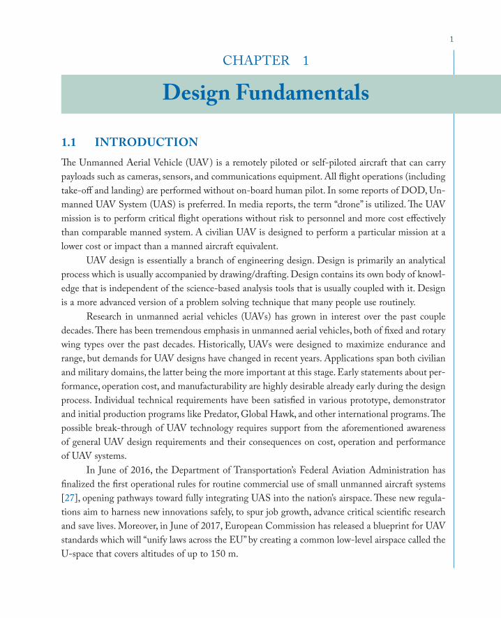
1.1 INTRODUCTIONThe Unmanned Aerial Vehicle (UAV) is a remotely piloted or self-piloted aircraft that can carry payloads such as cameras, sensors, and communications equipment. All flight operations (including take-off and landing) are performed without on-board human pilot. In some reports of DOD, Un-manned UAV System (UAS) is preferred. In media reports, the term “drone” is utilized. The UAV mission is to perform critical flight operations without risk to personnel and more cost effectively than comparable manned system. A civilian UAV is designed to perform a particular mission at a lower cost or impact than a manned aircraft equivalent.
UAV design is essentially a branch of engineering design. Design is primarily an analytical process which is usually accompanied by drawing/drafting. Design contains its own body of knowl-edge that is independent of the science-based analysis tools that is usually coupled with it. Design is a more advanced version of a problem solving technique that many people use routinely.
Research in unmanned aerial vehicles (UAVs) has grown in interest over the past couple decades. There has been tremendous emphasis in unmanned aerial vehicles, both of fixed and rotary wing types over the past decades. Historically, UAVs were designed to maximize endurance and range, but demands for UAV designs have changed in recent years. Applications span both civilian and military domains, the latter being the more important at this stage. Early statements about per-formance, operation cost, and manufacturability are highly desirable already early during the design process. Individual technical requirements have been satisfied in various prototype, demonstrator and initial production programs like Predator, Global Hawk, and other international programs. The possible break-through of UAV technology requires support from the aforementioned awareness of general UAV design requirements and their consequences on cost, operation and performance of UAV systems.
In June of 2016, the Department of Transportation’s Federal Aviation Administration has finalized the first operational rules for routine commercial use of small unmanned aircraft systems [27], opening pathways toward fully integrating UAS into the nation’s airspace. These new regula-tions aim to harness new innovations safely, to spur job growth, advance critical scientific research and save lives. Moreover, in June of 2017, European Commission has released a blueprint for UAV standards which will “unify laws across the EU” by creating a common low-level airspace called the U-space that covers altitudes of up to 150 m.
2 1. DESIGN FUNDAMENTALS
The design principles for UAVs are similar to the principles developed over the years and used successfully for the design of manned UAV. The size of UAV varies according to the purpose of their utility. In many cases the design and constructions of UAVs faces new challenges and, as a result of these new requirements, several recent works are concerned with the design of innovative UAVs. Autonomous vehicle technologies for small and large fixed-wing UAVs are being developed by various startups and established corporations such as Lockheed Martin. A number of concep-tual design techniques, preliminary design methodologies, and optimization has been applied to the design of various UAVs including Medium Altitude Long Endurance (MALE) UAV using multi-objective genetic algorithm.
The first UAV designs that appeared in the early nineties were based on the general de-sign principles for full UAV and findings of experimental investigations. The main limitation of civil UAV’s is often low cost. An important area of UAV technology is the design of autonomous systems. The tremendous increase of computing power in the last two decades and developments of general purpose reliable software packages made possible the use of full configuration design software packages for the design, evaluation, and optimization of modern UAV.
UAVs are air vehicles, they fly like airplanes and operate in an airplane environment. They are designed like air vehicles. They have to meet flight critical air vehicle requirements. You need to know how to integrate complex, multi-disciplinary systems. You need to understand the environ-ment, the requirements and the design challenges.
A UAV system is much more than a reusable air vehicle or vehicles. The UAV system includes five basic elements: (1) the Environment in which the UAV(s) or the Systems Element operates (e.g., the airspace, the data links, relay UAV, etc.); (2) the air vehicle(s) or the Air Vehicle Element; (3) the control station(s) or the Mission Control Element; (4) the payload(s) or the Payload Ele-ment; and (5) the maintenance and support system or the Support Element.
The design of manned UAV and the design of UAVs have some similarities; and some differ-ences such as: design process; constraints (e.g., g-load, pressurization); and UAV main components (autopilot, ground station, communication system, sensors, payload). A UAV designer must be aware of the: (1) latest UAV developments; (2) current technologies; and (3) known lessons learned from past failures. Designers should appreciate breadth of UAV design options.
UAV are not new, they have a long history in aviation. Their history stretches back to the First World War (1920s), Cold War, Korean War, Vietnam War (RPV), Yugoslavia, Afghanistan, First and Second Persian Gulf war, and other wars (e.g., Pakistan, Yemen, Syria, and Africa). At least 20 countries are using or developing over 76 different types of UAVs. The contributions of unmanned UAV in sorties, hours, and expanded roles continue to increase. As of September 2004, some 20 types of coalition UAVs, large and small, have flown over 100,000 total flight hours in support of Operation Enduring Freedom and Operation Iraqi Freedom. Their once reconnaissance-only role is now shared with strike, force protection, and signals collection.
3
In this chapter, definitions, design process, UAV classifications, current UAVs, and challenges will be covered. In addition, conceptual design, preliminary design, and detail design of a UAV based on systems engineering approach are introduced. In each stage, application of this approach is described by presenting the design flow chart and practical steps of design.
1.2 UAV CLASSIFICATIONSIt is a must for a UAV designer to be aware of classifications of UAVs which is based on various pa-rameters such as cost, size, weight, mission, and the user. For instance, UAV ranges in weight from Micro Air Vehicles (MAV) weighing less than 1 pound to UAV weighing over 40,000 lb. Moreover, these diverse systems range in cost from a few hundred dollars (Amazon sells varieties) to tens of millions of dollars (e.g., Global Hawk). In addition, UAV missions ranges from reconnaissance, combat, target acquisition, electronic warfare, surveillance, special purpose UAV, target and decoy, relay, logistics, research and development, and civil and commercial UAVs, to environmental appli-cation (e.g., University of Kansas North Pole UAV for measuring ice thickness).
The early classification includes target drones and remotely piloted vehicles (RPVs). The current classification ranges from Micro UAVs (less than 15 cm long, or 1 lb); to High-altitude Long Endurance (HALE); to tactical and combat UAVs. In this section, characteristics of various classifications are briefly presented.
The Micro Unmanned Aerial Vehicles (MAV) was originally a DARPA program to explore the military relevance of Micro Air Vehicles for future military operations, and to develop and demonstrate flight enabling technologies for very small UAV (less than 15 cm/6 in. in any dimen-sion). The Tactical UAV (e.g., Outrider) is designed to support tactical commanders with near-real-time imagery intelligence at ranges up to 200 km. The Joint Tactical UAV (Hunter) was developed to provide ground and maritime forces with near-real-time imagery intelligence at ranges up to 200 km. The Medium Altitude Endurance UAV (Predator) provides imagery intelligence to satisfy Joint Task Force and Theater Commanders at ranges out to 500 nautical miles. The High Altitude Endurance UAV (Global Hawk) is intended for missions requiring long-range deployment and wide-area surveillance or long sensor dwell over the target area. Table 1.1 shows the UAV classifi-cations from a few aspects including size, mass, and mission. The MLB Bat 4, a mini-UAV (Figure 2.7) with a length of 2.4 m, a wingspan of 3.9 m, and a maximum takeoff mass of 45 kg has a maximum cruising speed [54] of 120 knot.
In the U.S. military, the classification is mainly based on a tier system. For instance, in the U.S. Air Force the Tier I is for low altitude, long endurance missions, while Tier II is for medium altitude; long endurance (MALE) missions (e.g., Predator). Moreover, Tier II+ is for high-altitude, long-endurance (HALE) missions and Tier III- denotes HALE low observable. For other military forces, the following is the classification. Marine Corp: Tier I: Mini UAV; (e.g., Wasp, and MLB
1.2 UAV CLASSIFICATIONS

4 1. DESIGN FUNDAMENTALS
Bat); Tier II: (e.g., Pioneer); and Tier III: Medium range, (e.g., Shadow). Army: Tier I: Small UAV, (e.g., Raven); Tier II: Short range, tactical UAV, (e.g., Shadow 200); and Tier III: Medium range, tactical UAV.
Table 1.1: UAV classification
No. Class Mass SizeNormal Operating
AltitudeRange Endurance
1 Micro < 0.2 lb < 10 cm < 50 ft 0.1-0.5 km < 1 hr2 Mini 0.2-1 lb 10-30 cm < 100 ft 0.5-1 km < 1 hr3 Very small 2-5 lb 30-50 cm < 1000 ft 1-5 km 1-3 hr4 Small 5-20 lb 0.5-2 m 1,000-5,000 ft 10-100 km 0.5-2 hr5 Medium 100-1,000 lb 5-10 m 10,000-15,000 ft 500-2,000 km 3-10 hr6 Large 10,000-
30,000 lb20-50 m 20,000-40,000 ft 1,000-5,000
km10-20 hr
7 Tactical/ combat
1,000-20,000 lb
10-30 m 10,000-30,000 ft 500-2,000 km 5-12 hr
8 MALE 1,000-10,000 lb
15-40 m 15,000-30,000 ft 20,000-40,000 km
20-40 hr
9 HALE > 5,000 lb 20-50 m 50,000-70,000 ft 20,000-40,000 km
30-50 hr
Another basis for UAVs classifications in military is echelon: Class 1 supports platoon ech-elon, (e.g., Raven), micro air vehicle (MAV), and small UAV; Class 2 supports company echelon, (e.g., Interim Class 1 and 2 UAV); Class 3 supports battalion echelon, (e.g., Shadow 200 Tactical UAV); and Class 4 supports unit of action (brigade), (e.g., Hunter), Extended Range/Multipurpose (ER/MP) UAV.
Some current U.S. UAVs [46] are listed here: (1) Army UAV Systems: RQ-1L I-GNAT Organization; RQ-5/MQ-5 Hunter Aerial Reconnaissance Company; RQ-7 Shadow Aerial Re-connaissance Platoon; RQ-11 Raven Team. (2) Air Force UAV Systems: RQ-4 Global Hawk; RQ/MQ-1 Predator; MQ-9 Predator B; Force Protection Aerial Surveillance System, Desert Hawk (Figure 8.3). (3) Navy UAV Systems: RQ-2 Pioneer; RQ-8B Fire Scout. (4) Marine Corps UAV Systems: FQM-151 Pointer; Dragon Eye; Silver Fox; Scan Eagle. (5) Coast Guard UAV Systems: Eagle Eye. (6) Special Operations Command UAV Systems: CQ-10 SnowGoose; FQM-151 Pointer; RQ-11 Raven; Dragon Eye.
It will be very helpful to know the features of some old and current UAVs. Hunter (RQ-5): Range: 125 km; Max speed: 110 knots; Dimensions: length: 22.6 ft; span: 29.2 ft; Endurance: 10 hr; Weights: Max Takeoff: 1600 lb; Ceiling: 16,000 ft. Hunter, was cancelled in January 1996 after

5
some 20 air vehicle crashes. Pioneer RQ-2A: First flight: 1985; Dimensions: length: 14 ft span: 16.9 ft; Max. TO Weight: 450 lb; Speeds: cruise: 65 knots; dash: 110 knots; it was used extensively in Falujeh, Iraq, 2006. During Operations Desert Shield, the U.S. deployed 43 Pioneers that flew 330 sorties, completing over 1,000 flight hours. In 10 years, Pioneer system has flown nearly 14,000 flight hours. Since 1994, it has flown over Bosnia, Haiti, and Somalia.
Outrider: First flight: 2,000; Range: 200 km; Wing span: 11.1 ft; MTOW: 385 lb; Ceiling: 15,000 ft; Max speed: 110 knot; Endurance: 7.2 hr. Predator RQ-1A (Figure 5.4): First flight: 1994; Endurance: 25 hr; Ceiling: 26,000; Payload: 450 lb; Cruise Speed: 90 knots; MTOW: 2100 lb; Wing span: 48.4 ft. Extensively employed in Iraq, Afghanistan, Pakistan, … Predator RQ-1B (Figure 4.10): Honeywell TPE-331-10T, flat-rated to 750 shp; 4,500 kg take-off gross weight; Max speed/altitude: 210 knot/50Kft; - 20 m wingspan; Triplex systems; 1,360 kg fuel; 340 kg in-ternal payload; 1360 kg external payload; 6 store stations/14 Hellfire missiles.
Figure 1.1: Northrop Grumman RQ-4 Global Hawk.
• Global Hawk RQ-4 (Figure 1.1): First flight was in 1998; Endurance: 41 hr; Ceiling: 65,000; Payload: 2,000 lb; Ranges: 14,000 nm; Cruise Speed: 345 knots; MTOW: 25,500 lb; Wing span: 116 ft. The Defense Advanced Research Projects Agency (DARPA) developed Global Hawk to provide military field commanders with a high-altitude, long-endurance system that can obtain high-resolution, near-real-time imagery of large geographic areas. Flew for the first time at Edwards Air Force Base, California, on Saturday, February 28, 1998. The entire mission, including the take-off and landing, was performed autonomously by the UAV based on its mission plan. The
1.2 UAV CLASSIFICATIONS

6 1. DESIGN FUNDAMENTALS
launch and recovery element of the system’s ground segment continuously monitored the status of the flight.
1.3 DESIGN PROJECT PLANNINGIn order for a design project schedule to be effective, it is necessary to have some procedures for monitoring progress; and in a broader sense for encouraging personnel to progress. An effective general form of project management control device is the Gantt chart is. It presents a project overview which is almost immediately understandable to non-systems personnel; hence it has great value as a means of informing management of project status. A Gantt chart has three main features.
1. It informs the manager and chief designer of what tasks are assigned and who has been assigned to them.
2. It indicated the estimated dates on which tasks are assumed to start and end, and it represents graphically the estimated ration of the task.
3. It indicates the actual dates on which tasks were started and completed and pictures this information.
Like many other planning/management tools, Gantt charts provide the manager/chief de-signer with an early warning if some jobs will not be completed on schedule and/or if others are ahead of schedule. Gantt charts are also helpful in that they present graphically immediate feedback regarding estimates of personnel skill and job complexity. A Gantt chart provides the chief designer with a scheduling method and enables him/her to rapidly track and assess the design activities on a weekly/monthly basis. An aircraft project such as Global Hawk (Figure 1.1) will not be successful without a design project planning.
1.4 DECISION MAKINGNot every design parameters is the outcome of a mathematical/technical calculations. There are UAV parameters which are determined through a selection process. In such cases, the designer should be aware of the decision making procedures. The main challenge in decision making is that there are usually multiple criteria along with a risk associated with each one. Any engineering selection must be supported by logical and scientific reasoning and analysis. The main challenge in decision making is that there are usually multiple criteria along with a risk associated with each one. There are no straightforward governing equations to be solved mathematically.
A designer must recognize the importance of making the best decision and the adverse of consequence of making the poorest decision. In majority of the design cases, the best decision is the right decision, and the poorest decision is the wrong one. The right decision implies the design suc-
7
cess, and the wrong decision results in a fail in the design. As the level of design problem complexity and sophistication increases in a particular situation, a more sophisticated approach is needed.
1.5 DESIGN CRITERIA, OBJECTIVES, AND PRIORITIESOne of the preliminary tasks in UAV configuration design is identifying system design consider-ations. The definition of a need at the system level is the starting point for determining customer requirements and developing design criteria. The requirements for the system as an entity are established by describing the functions that must be performed. Design criteria constitute a set of “design-to” requirements, which can be expressed in both qualitative and quantitative terms. De-sign criteria are customer specified or negotiated target values for technical performance measures. These requirements represent the bounds within which the designer must “operate” when engaged in the iterative process of synthesis, analysis, and evaluation. Both operational functions (i.e., those required to accomplish a specific mission scenario, or series of missions) and maintenance and support functions (i.e., those required to ensure that the UAV is operational when required) must be described at the top level.
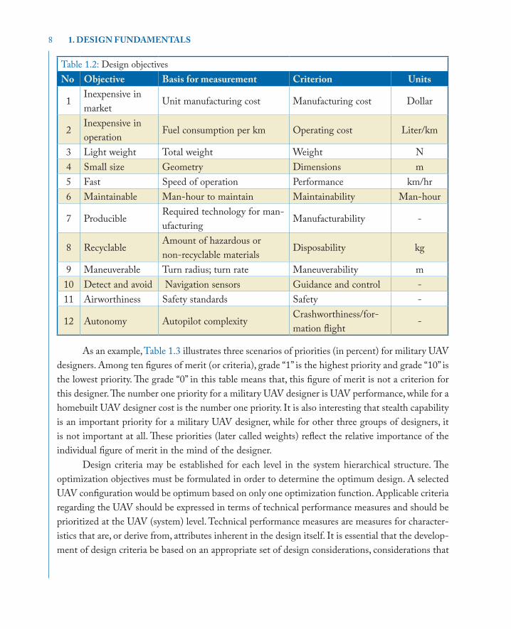
Various UAV designer have different priorities in their design processes. These priorities are based on different objectives, requirements ,and mission. There are primarily three groups of UAV designers, namely: (1) military UAV designers, (2) civil UAV designers, and (3) homebuilt UAV de-signers. These three groups of designers have different interests, priorities, and design criteria. There are ten main figures of merit for every UAV configuration designer. They are: (1) production cost, (2) UAV performance, (3) flying qualities, (4) design period, (5) beauty (for civil UAV) or scariness (for military UAV), (6) maintainability, (7) producibility, (8) UAV weight, (9) disposability, and (10) stealth requirement. Table 1.2 demonstrates objectives and priorities of each UAV designer against some figures of merit.
In design evaluation, an early step that fully recognizes design criteria is to establish a base-line against which a given alternative or design configuration may be evaluated. This baseline is de-termined through the iterative process of requirements analysis (i.e., identification of needs, analysis of feasibility, definition of UAV operational requirements, selection of a maintenance concept, and planning for phase-out and disposal). The mission that the UAV must perform to satisfy a specific customer should be described, along with expectations for cycle time, frequency, speed, cost, effec-tiveness, and other relevant factors. Functional requirements must be met by incorporating design characteristics within the UAV and its configuration components.
1.5 DESIGN CRITERIA, OBJECTIVES, AND PRIORITIES
8 1. DESIGN FUNDAMENTALS
Table 1.2: Design objectivesNo Objective Basis for measurement Criterion Units
1Inexpensive in market
Unit manufacturing cost Manufacturing cost Dollar
2Inexpensive in operation
Fuel consumption per km Operating cost Liter/km
3 Light weight Total weight Weight N 4 Small size Geometry Dimensions m5 Fast Speed of operation Performance km/hr6 Maintainable Man-hour to maintain Maintainability Man-hour
7 ProducibleRequired technology for man-ufacturing
Manufacturability -
8 Recyclable Amount of hazardous or non-recyclable materials
Disposability kg
9 Maneuverable Turn radius; turn rate Maneuverability m10 Detect and avoid Navigation sensors Guidance and control -11 Airworthiness Safety standards Safety -
12 Autonomy Autopilot complexityCrashworthiness/for-mation flight
-
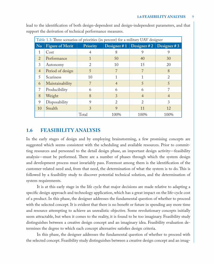
As an example, Table 1.3 illustrates three scenarios of priorities (in percent) for military UAV designers. Among ten figures of merit (or criteria), grade “1” is the highest priority and grade “10” is the lowest priority. The grade “0” in this table means that, this figure of merit is not a criterion for this designer. The number one priority for a military UAV designer is UAV performance, while for a homebuilt UAV designer cost is the number one priority. It is also interesting that stealth capability is an important priority for a military UAV designer, while for other three groups of designers, it is not important at all. These priorities (later called weights) reflect the relative importance of the individual figure of merit in the mind of the designer.
Design criteria may be established for each level in the system hierarchical structure. The optimization objectives must be formulated in order to determine the optimum design. A selected UAV configuration would be optimum based on only one optimization function. Applicable criteria regarding the UAV should be expressed in terms of technical performance measures and should be prioritized at the UAV (system) level. Technical performance measures are measures for character-istics that are, or derive from, attributes inherent in the design itself. It is essential that the develop-ment of design criteria be based on an appropriate set of design considerations, considerations that
9
lead to the identification of both design-dependent and design-independent parameters, and that support the derivation of technical performance measures.
Table 1.3: Three scenarios of priorities (in percent) for a military UAV designerNo Figure of Merit Priority Designer # 1 Designer # 2 Designer # 3
1 Cost 4 8 9 92 Performance 1 50 40 303 Autonomy 2 10 15 204 Period of design 5 7 7 85 Scariness 10 1 1 26 Maintainability 7 4 5 57 Producibility 6 6 6 78 Weight 8 3 4 49 Disposability 9 2 2 310 Stealth 3 9 11 12
Total 100% 100% 100%
1.6 FEASIBILITY ANALYSISIn the early stages of design and by employing brainstorming, a few promising concepts are suggested which seems consistent with the scheduling and available resources. Prior to commit-ting resources and personnel to the detail design phase, an important design activity—feasibility analysis—must be performed. There are a number of phases through which the system design and development process must invariably pass. Foremost among them is the identification of the customer-related need and, from that need, the determination of what the system is to do. This is followed by a feasibility study to discover potential technical solution, and the determination of system requirements.
It is at this early stage in the life cycle that major decisions are made relative to adapting a specific design approach and technology application, which has a great impact on the life-cycle cost of a product. In this phase, the designer addresses the fundamental question of whether to proceed with the selected concept. It is evident that there is no benefit or future in spending any more time and resource attempting to achieve an unrealistic objective. Some revolutionary concepts initially seem attractable, but when it comes to the reality, it is found to be too imaginary. Feasibility study distinguishes between a creative design concept and an imaginary idea. Feasibility evaluation de-termines the degree to which each concept alternative satisfies design criteria.
In this phase, the designer addresses the fundamental question of whether to proceed with the selected concept. Feasibility study distinguishes between a creative design concept and an imag-
1.6 FEASIBILITY ANALYSIS

10 1. DESIGN FUNDAMENTALS
inary idea. Feasibility evaluation determines the degree to which each concept alternative satisfies design criteria.
In the feasibility analysis, the answers to the following two questions are sought: (1) Are the goals achievable?; or are the objectives realistic?; or are the design requirements meetable? and (2) Is the current design concept feasible? If the answer to the first question is no, the design goal and objectives, and design requirements must be changed. Hence, no matter where is the source of design requirements; either direct customer order or market analysis; they must be changed.
1.7 DESIGN GROUPSAn aircraft chief designer should be capable of covering and handling a broad spectrum of activities. Thus, an aircraft chief designer should have years of experiences, be knowledgeable of management techniques, and preferably have full expertise and background in the area of “flight dynamics.” The chief designer has a great responsibility in planning, coordination, and conducting formal design reviews. He/she must also monitor and review aircraft system test and evaluation activities, as well as coordinating all formal design changes and modifications for improvement. The organization must be such that facilitate the flow of information and technical data among various design departments. The design organization must allow the chief designer to initiate and establish the necessary ongoing liaison activities throughout the design cycle.
A primary building block is organizational patterns is the functional approach, which in-volves the grouping of functional specialties or disciplines into separately identifiable entities. The intent is to perform similar work within one organizational group. Thus, the same organizational group will accomplish the same type of work for all ongoing projects on a concurrent basis. The ultimate objective is to establish a team approach, with the appropriate communications, enabling the application of concurrent engineering methods throughout.
Chief Designer
Structure Aerodynamics Propulsion AutopilotFlightDynamics
GroundStation
Launch &Recovery
Figure 1.2: UAV main design groups.
There are two main approaches to handle the design activities and establishing design groups: (1) design groups based on aircraft components, and (2) design groups based on expertise (Figure 1.2). If the approach of groups based on aircraft components is selected, the chief designer must establish the following teams: (1) wing design team, (2) tail design team, (3) fuselage design team, (4) propulsion system design team, (5) landing gear design team, (6) autopilot design team, (7)

11
ground station design team, and (8) launch and recovery design team. The ninth team is established for documentation, and drafting. There are various advantages and disadvantages for each of the two planning approaches in terms of ease of management, speed of communication, efficiency, and similarity of tasks. However, if the project is large, such as the design of a large transport aircraft, both groupings could be applied simultaneously.
1.8 DESIGN PROCESSUAV Design is an iterative process which involves synthesis, analysis, and evaluation. Figure 1.3 demonstrates the design process block diagram. Design (i.e., synthesis) is the creative process of putting known things together into new and more useful combinations. Analysis refers to the process of predicting the performance or behavior of a design candidate. Evaluation is the pro-cess of performance calculation and comparing the predicted performance of each feasible design candidate to determine the deficiencies. A design process requires both integration and iteration. There is an interrelationship between synthesis, analysis, and evaluation. Two main groups of design activities are: (1) problem solving through mathematical calculations, and (2) choosing a preferred one among alternatives.
Conceptual/preliminary
design
Detaildesign and
development
Productionand/or
construction
Product use, supportphase out, and
disposal
NEED
Acquisition Phase Utilization Phase
Figure 1.3: The UAV life-cycle.
In general, design considerations are the full range of attributes and characteristics that could be exhibited by an engineered system, product, or structure. These interest both the producer and the customer. Design-dependent parameters are attributes and/or characteristics inherent in the design to be predicted or estimated (e.g., weight, design life, reliability, producibility, maintain-ability, and disposability). These are a subset of the design considerations for which the producer is primarily responsible. On the other hand, design-independent parameters are factors external to the design that must be estimated and forecasted for use in design evaluation (e.g., fuel cost per gallon, interest rates, labor rates, and material cost per pound). These depend upon the production and operating environment of the UAV.
A goal statement is a brief, general, and ideal response to the need statement. The objectives are quantifiable expectations of performance which identify those performance characteristics of
1.8 DESIGN PROCESS
12 1. DESIGN FUNDAMENTALS
a design that are of most interest to the customer. Restrictions of function of form are called con-straints; they limit our freedom to design.
1.9 SYSTEMS ENGINEERING APPROACHComplex UAV systems, due to the high cost and the risks associated with their development become a prime candidate for the adoption of systems engineering methodologies. The UAV conceptual design process has been documented in many texts, and the interdisciplinary nature of the system is immediately apparent. A successful configuration designer needs not only a good understanding of design, but also systems engineering approach. A competitive configuration de-sign manager must have a clear idea of the concepts, methodologies, models, and tools needed to understand and apply systems engineering to UAV systems.
The design of a UAV begins with the requirements definition and extends through functional analysis and allocation, design synthesis and evaluation, and finally validation. An optimized UAV, with a minimum of undesirable side effects, requires the application of an integrated life-cycle ori-ented “system” approach. The design of the configuration for the UAV begins with the requirements definition and extends through functional analysis and allocation, design synthesis and evaluation, and finally validation. Operations and support needs must be accounted for in this process. An op-timized UAV, with a minimum of undesirable side effects, requires the application of an integrated life-cycle oriented “system” approach.
The design of the UAV subsystems plays a crucial role in the configuration design and their operation. These subsystems turn an aerodynamically shaped structure into a living, breathing, unmanned flying machine. These subsystems include the: flight control subsystem, power transmis-sion subsystem, fuel subsystem, structures, propulsion, aerodynamics, and landing gear. In the early stages of a conceptual or a preliminary design these subsystems must initially be defined, and their impact must be incorporated into the design layout, weight analysis, performance calculations, and cost benefits analysis.
A UAV is a system composed of a set of interrelated components working together toward some common objective or purpose. Primary objectives include safe flight achieved at a low cost. Every system is made up of components or subsystems, and any subsystem can be broken down into smaller components. For example, in an air transportation system, the UAV, terminal, ground support equipment, and controls are all subsystems. The UAV life-cycle is illustrated in Figure 1.3.
A UAV must feature product competitiveness, otherwise, the producer and designer may not survive in the world marketplace. Product competitiveness is desired by UAV producers worldwide. Accordingly, the systems engineering challenge is to bring products and systems into being that meet the mission expectations cost-effectively. Because of intensifying international competition, UAV producers are seeking ways to gain sustainable competitive advantages in the marketplace.
13
It is essential that UAV designers be sensitive to utilization outcomes during the early stages of UAV design and development. They also need to conduct life-cycle engineering as early as possible in the design process. Fundamental to the application of systems engineering is an under-standing of the system life-cycle process illustrated in Figure 1.3. It must simultaneously embrace the life cycle of the manufacturing process, the life cycle of the maintenance and support capability, and the life cycle of the phase-out and disposal process.
The requirements need for a specific new UAV first comes into focus during the conceptual design process. It is this recognition that initiates the UAV conceptual design process to meet these needs. Then, during the conceptual design of the UAV, consideration should simultaneously be given to its production and support. This gives rise to a parallel life cycle for bringing a manufac-turing capability into being.
Traditional UAV configuration design attempts to achieve improved performance and re-duced operating costs by minimizing maximum takeoff weight. From the point of view of a UAV customer, however, this method does not guarantee the optimality of a UAV program. Multidisci-plinary design optimization (MDO) is an important part of the UAV configuration design process. It first discusses the design parameters, constraints, objectives functions, and criteria and then UAV configuration classifications. Then the relationship between each major design option and the de-sign requirements are evaluated. Then the systems engineering principals are presented. At the end, systems engineering approach is applied in the optimization of the UAV configuration design and a new configuration design optimization methodology is introduced.
The design of a UAV within the system life-cycle context is different from the design just to meet a set of performance or stability requirements. Life-cycle focused design is simultaneously responsive to customer needs and to life-cycle outcomes. The design of the UAV should not only transform a need into a UAV/system configuration, but should ensure the UAV’s compatibility with related physical and functional requirements. Further, it should consider operational outcomes expressed as safety, producibility, affordability, reliability, maintainability, usability, supportability, serviceability, disposability, and others, as well as the requirements on performance, stability, control, and effectiveness.
An essential technical activity within this process is that of evaluation. Evaluation must be inherent within the systems engineering process and must be invoked regularly as the system de-sign activity progresses. However, systems evaluation should not proceed without guidance from customer requirements and specific system design criteria. When conducted with full recognition of design criteria, evaluation is the assurance of continuous design improvement. There are a num-ber of phases through which the system design and development process must invariably pass. Foremost among them is the identification of the customer related need and, from that need, the determination of what the system is to do. This is followed by a feasibility analysis to discover po-tential technical solutions, the determination of system requirements, the design and development
1.9 SYSTEMS ENGINEERING APPROACH

14 1. DESIGN FUNDAMENTALS
of system components, the construction of a prototype, and/or engineering model, and the valida-tion of system design through test and evaluation. The system (e.g., UAV) design process includes four major phases: (1) Conceptual Design, (2) Preliminary Design, (3) Detail Design, and (4) Test and Evaluation.The four phases of the integrated design of a UAV are summarized in Figure 1.4. Sections 1.10–1.13 present the details of these design phases.
Design Requirements
Conceptual Design
Preliminary Design
Detail Design - Part I
Detail Design - Part II
Production /Construction
CDR
PDR
FDR
ETR
Disapprove
Disapprove
Disapprove
Approve
Approve
Approve
Approve
Disapprove
Figure 1.4: Design process and formal design reviews.
In the conceptual design phase, the UAV will be designed in concept without the precise calculations. In another word, almost all parameters are determined based on a decision making process and a selection technique. On the other hand, the preliminary design phase tends to employ the outcomes of a calculation procedure. As the name implies, in the preliminary design phase, the
15
parameters that are determined are not final and will be altered later. In addition, in this phase, parameters are essential and will directly influence the entire detail design phase. Therefore the ultimate care must be taken to insure the accuracy of the results of the preliminary design phase. In the detail design phase, the technical parameters of all components (e.g., wing, fuselage, tail, landing gear (LG), and engine) including geometry are calculated and finalized.
1.10 CONCEPTUAL DESIGNThroughout the conceptual system design phase (commencing with the need analysis), one of the major objectives is to develop and define the specific design-to requirements for the system as an entry. The results from these activities are combined, integrated, and included in a system specification. This specification constitutes the top “technical-requirements” document that pro-vides overall guidance for system design from the beginning. Conceptual design is the first and most important phase of the UAV system design and development process. It is an early and high-level life cycle activity with potential to establish, commit, and otherwise predetermine the function, form, cost, and development schedule of the desired UAV system. The identification of a problem and associated definition of need provides a valid and appropriate starting point for design at the conceptual level.
Selection of a path forward for the design and development of a preferred system configu-ration, which will ultimately be responsive to the identified customer requirement, is a major re-sponsibility of conceptual design. Establishing this early foundation, as well as requiring the initial planning and evaluation of a spectrum of technologies, is a critical first step in the implementation of the systems engineering process. Systems engineering, from an organizational perspective, should take the lead in the definition of system requirements from the beginning and address them from a total integrated life-cycle perspective.
As the name implies, the UAV conceptual design phase is the UAV design at the concept level. At this stage, the general design requirements are entered in a process to generate a satisfac-tory configuration. The primary tool in this stage of design is the “selection.” Although there are variety of evaluation and analysis, but there are no much calculation. The past design experience plays a crucial role in the success of this phase. Hence, the members of conceptual design phase team must be the most experienced engineers of the corporation. Figure 1.5 illustrates the major activities which are practiced in the UAV conceptual design phase. The fundamental output of this phase is an approximate three-view of the UAV that represents the UAV configuration.
1.0 CONCEPTUAL DESIGN

16 1. DESIGN FUNDAMENTALS
UAV Design Requirements(Mission, Performance, Stability, Control, Cost, Operational, Time, Manufacturing)
Identify major components that the UAV requires to satisfy the design requirements
UAV Approximate 3-view (without dimensions)
Con�guration Optimization
UAV Con�guration
WingCon�guration
TailCon�guration
EngineCon�guration
Landing GearCon�guration
StructuralCon�guration
AutopilotCon�guration
Figure 1.5: UAV conceptual design.
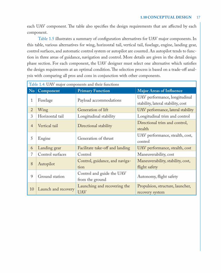
A UAV comprised of several major components. It mainly includes wing, horizontal tail, ver-tical tail, fuselage, propulsion system, landing gear, control surfaces, and autopilot. In order to make a decision about the configuration of each UAV component, the designer must be fully aware of the function of each component. Each UAV component has inter-relationships with other components and interferes with the functions of other components. The above six components are assumed to be the fundamental components of an air vehicle. However, there are other components in a UAV that are not assumed here as a major one. The roles of those components are described in the later sections whenever they are mentioned. Table 1.4 illustrates a summary of UAV major components and their functions. This table also shows the secondary roles and the major areas of influence of
17
each UAV component. The table also specifies the design requirements that are affected by each component.
Table 1.5 illustrates a summary of configuration alternatives for UAV major components. In this table, various alternatives for wing, horizontal tail, vertical tail, fuselage, engine, landing gear, control surfaces, and automatic control system or autopilot are counted. An autopilot tends to func-tion in three areas of guidance, navigation and control. More details are given in the detail design phase section. For each component, the UAV designer must select one alternative which satisfies the design requirements at an optimal condition. The selection process is based on a trade-off anal-ysis with comparing all pros and cons in conjunction with other components.
Table 1.4: UAV major components and their functionsNo Component Primary Function Major Areas of Influence
1 Fuselage Payload accommodations UAV performance, longitudinal stability, lateral stability, cost
2 Wing Generation of lift UAV performance, lateral stability3 Horizontal tail Longitudinal stability Longitudinal trim and control
4 Vertical tail Directional stabilityDirectional trim and control, stealth
5 Engine Generation of thrustUAV performance, stealth, cost, control
6 Landing gear Facilitate take-off and landing UAV performance, stealth, cost7 Control surfaces Control Maneuverability, cost
8 AutopilotControl, guidance, and naviga-tion
Maneuverability, stability, cost, flight safety
9 Ground stationControl and guide the UAV from the ground
Autonomy, flight safety
10 Launch and recoveryLaunching and recovering the UAV
Propulsion, structure, launcher, recovery system
1.10 CONCEPTUAL DESIGN

18 1. DESIGN FUNDAMENTALS
Table 1.5: UAV major components with design alternativesNo Component Configuration Alternatives
1 Fuselage- Geometry: lofting, cross section- Internal arrangement - What to accommodate (e.g., fuel, engine, and landing gear)?
2 Wing
- Type: swept, tapered, dihedral;- Location: low-wing, mid-wing, high wing, parasol- High lift device: flap, slot, slat- Attachment: cantilever, strut-braced
3 Horizontal tail- Type: conventional, T-tail, H-tail, V-tail, inverted V - Installation: fixed, moving, adjustable- Location: aft tail, canard, three surfaces
4 Vertical tail Single, twin, three VT, V-tail
5 Engine- Type: turbofan, turbojet, turboprop, piston-prop, rocket- Location: (e.g., under fuselage, under wing, beside fuselage)- Number of engines
6 Landing gear- Type: fixed, retractable, partially retractable - Location: (e.g., nose, tail, multi)
7 Control surfacesSeparate vs. all moving tail, reversible vs. irreversible, conventional vs. non-conventional (e.g., elevon, ruddervator)
8 Autopilot
- UAV: Linear model, nonlinear model- Control subsystem: PID, gain scheduling, optimal, QFT, robust, adaptive, intelligent- Guidance subsystem: Proportional Navigation Guidance, Line Of Sight, Command Guidance, three point, Lead- Navigation subsystem: Inertial navigation (Strap down, stable plat-form), GPS
9Launch and recovery
HTOL, ground launcher, net recovery, belly landing
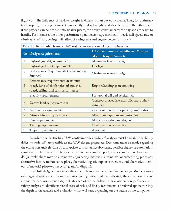
In order to facilitate the conceptual design process, Table 1.6 shows the relationship between UAV major components and the design requirements. The third column in Table 1.6 clarifies the UAV component which affected most; or major design parameter by a design requirement. Every design requirement will normally affects more than one component, but we only consider the com-ponent that is influenced most. For example, the payload requirement, range and endurance will affect maximum take-off weight, maximum take-off weight, engine selection, fuselage design, and
19
flight cost. The influence of payload weight is different than payload volume. Thus, for optimiza-tion purpose, the designer must know exactly payload weight and its volume. On the other hand, if the payload can be divided into smaller pieces, the design constraints by the payload are easier to handle. Furthermore, the other performance parameters (e.g., maximum speed, stall speed, rate of climb, take-off run, ceiling) will affect the wing area and engine power (or thrust).
Table 1.6: Relationship between UAV major components and design requirements
No Design RequirementsUAV Component that Affected Most, or Major Design Parameter
1 Payload (weight) requirements Maximum take-off weightPayload (volume) requirements Fuselage
2Performance Requirements (range and en-durance)
Maximum take-off weight
3Performance requirements (maximum speed, Rate of climb, take-off run, stall speed, ceiling, and turn performance)
Engine; landing gear; and wing
4 Stability requirements Horizontal tail and vertical tail
5 Controllability requirementsControl surfaces (elevator, aileron, rudder), autopilot
6 Autonomy requirements Center of gravity, autopilot, ground station 7 Airworthiness requirements Minimum requirements, autopilot8 Cost requirements Materials; engine; weight, etc. 9 Timing requirements Configuration optimality10 Trajectory requirements Autopilot
In order to select the best UAV configuration, a trade-off analysis must be established. Many different trade-offs are possible as the UAV design progresses. Decisions must be made regarding the evaluation and selection of appropriate components, subsystems, possible degree of automation, commercial off-the-shelf parts, various maintenance and support policies, and so on. Later in the design cycle, there may be alternative engineering materials, alternative manufacturing processes, alternative factory maintenance plans, alternative logistic support structures, and alternative meth-ods of material phase-out, recycling, and/or disposal.
The UAV designer must first define the problem statement, identify the design criteria or mea-sures against which the various alternative configurations will be evaluated, the evaluation process, acquire the necessary input data, evaluate each of the candidate under consideration, perform a sen-sitivity analysis to identify potential areas of risk, and finally recommend a preferred approach. Only the depth of the analysis and evaluation effort will vary, depending on the nature of the component.
1.10 CONCEPTUAL DESIGN
20 1. DESIGN FUNDAMENTALS
Trade-off analysis involves synthesis which refers to the combining and structuring of com-ponents to create a UAV system configuration. Synthesis is design. Initially, synthesis is used in the development of preliminary concepts and to establish relationships among various components of the UAV. Later, when sufficient functional definition and decomposition have occurred, synthesis is used to further define “hows” at a lower level. Synthesis involves the creation of a configuration that could be representative of the form that the UAV will ultimately take (although a final config-uration should not be assumed at this early point in the design process).
One of the most effective techniques in trade-off studies is multidisciplinary design optimi-zation. Researchers in academia, industry, and government continue to advance Multidisciplinary Design Optimization (MDO) and its application to practical problems of industry relevance. Multidisciplinary design optimization is a field of engineering that uses optimization methods to solve design problems incorporating a number of disciplines. Multidisciplinary design optimization allows designers to incorporate all relevant disciplines simultaneously. The optimum solution of a simultaneous problem is superior to the design found by optimizing each discipline sequentially, since it can exploit the interactions between the disciplines. However, including all disciplines si-multaneously significantly increases the complexity of the design problem.
1.11 PRELIMINARY DESIGNFour fundamental UAV parameters are determined during the preliminary design phase: (1) UAV maximum take-off weight (WTO), (2) wing reference area (S), (3) engine thrust (T) or engine power (P), and (4) autopilot preliminary calculations. Hence, four primary UAV parameters of WTO, S, T (or P), and several autopilot data are the output of the preliminary design phase. These four parameters will govern the UAV size, the manufacturing cost, and the complexity of calcula-tion. If during the conceptual design phase, a jet engine is selected, the engine thrust is calculated during this phase. But, if during the conceptual design phase, a prop-driven engine is selected, the engine power is calculated during this phase. A few other non-important UAV parameters such as UAV zero-lift drag coefficient and UAV maximum lift coefficient are estimated in this phase too.
Figure 1.6 illustrates a summary of the preliminary design process. The preliminary design phase is performed in three steps: (1) estimate UAV maximum take-off weight; (2) determine wing area and engine thrust (or power) simultaneously; and (3) autopilot preliminary calculations.
In this design phase, three design techniques are employed. First, a technique based on the statistics is used to determine UAV maximum take-off weight. The design requirements which are used in this technique are flight mission, payload weight, range, and endurance.
Next, another technique is employed based on the UAV performance requirements (such as stall speed, maximum speed, range, rate of climb, and take-off run) to determine the wing area and the engine thrust (or engine power). This technique is sometime referred to as the matching plot

21
or matching chart, due to its graphical nature and initial sizing. The principles of the matching plot technique are originally introduced in a NASA technical report and they were later developed by Sadraey [37]. The technique is further developed by the author in his new book on UAV design that is under publication.
UAV Performance Design Requirements(Maximum Speed, Range, Endurance, Take-o� Run, Stall Speed, Maneuverability, Payload, etc.)
Determine UAV maximum take-o� weight (WTO)
Determine autopilot primary characteristics
Determine wing area (Sref) and engine thrust (T) (or Power (P))
Output: WTO, Sref, and T (or P), and autopilot con�guration
Figure 1.6: Preliminary design procedure.
In general, the first technique is not accurate (in fact, it is an estimation) and the approach may carry some inaccuracies, while the second technique is very accurate and the results are reli-able. Due to the length of the book, the details of these three techniques have not been discussed in details here in this section. It is assumed that the reader is aware of these techniques which are practiced in many institutions.
1.12 DETAIL DESIGNThe design of the UAV subsystems and components plays a crucial role in the success of the flight operations. These subsystems turn an aerodynamically shaped structure into a living, breathing, un-manned flying machine. These subsystems include the: wing, tail, fuselage, flight control subsystem, power transmission subsystem, fuel subsystem, structures, propulsion, landing gear, and autopilot. In the early stages of a conceptual or a preliminary design phase, these subsystems must initially be defined, and their impact must be incorporated into the design layout, weight analysis, perfor-mance/stability calculations, and cost benefits analysis. In this section, the detail design phase of a UAV is presented.
1.11 PRELIMINARY DESIGN

22 1. DESIGN FUNDAMENTALS
Preliminary Design
Subsystem Functional Analysis
Meet Requirements?
Mathematical Model and Prototype Test and Evaluation
Release of Documentations (Drawings) for System Production/Construction
Design Subsystems
Meet Requirements?
Design Components
Design Parts/Elements
Design Review
Yes
No
No
Disapprove
Approve
Yes
Figure 1.7: Detail design sequence.
As the name implies, in the detail design phase, the details of parameters of all major components (Figure 1.7) of a UAV is determined. This phase is established based on the results of conceptual design phase and preliminary design phase. Recall that the UAV configuration has been determined in the conceptual design phase and wing area, engine thrust, and autopilot major features have been set in preliminary design phase. The parameters of wing, horizontal tail, vertical tail, fuselage, landing gear, engine, subsystems, and autopilot must be determined in this last design phase. To compare three design phases, the detail design phase contains a huge amount of calcula-tions and a large mathematical operation compared with other two design phases. If the total length of a UAV design is considered to be one year, about ten months is spent on the detail design phase.

23
This phase is an iterative operation in its nature. In general, there are four design feedbacks in the detail design phase. Figure 1.4 illustrates the relationships between detail design and design feedbacks. Four feedbacks in the detail design phase are: (1) performance evaluation, (2) stability analysis, (3) controllability analysis, and (4) flight simulation. The UAV performance evaluation includes the determination of UAV zero-lift drag coefficient. The stability analysis requires the component weight estimation plus the determination of UAV center of gravity (cg). In the control-lability analysis operation, the control surfaces (e.g., elevator, aileron, and rudder) must be designed. When the autopilot is designed, the UAV flight needs to be simulated to assure the flight success.
As the name implies, each feedback is performed to compare the output with the input and correct the design to reach the design goal. If the performance requirements are not achieved, the design of several components, such as engine and wing, might be changed. If the stability require-ments are not met, the design of several components, such as wing, horizontal tail and vertical tail could be changed. If the controllability evaluation indicates that the UAV does not meet con-trollability requirements, control surfaces and even engine must be redesigned. In case that both stability requirements and controllability requirements were not met, the several components must be moved to change the cg location.
In some instances, this deficiency may lead to a major variation in the UAV configuration, which means the designer needs to return to the conceptual design phase and begin the correction from the beginning. The deviation of the UAV from trajectory during flight simulation necessitates a change in autopilot design.
1.13 DESIGN REVIEW, EVALUATION, AND FEEDBACKIn each major design phase (conceptual, preliminary, and detail), an evaluation should be conducted to review the design and to ensure that the design is acceptable at that point before proceeding with the next stage. There is a series of formal design reviews conducted at specific times in the overall system development process. An essential technical activity within the design process is that of evaluation. Evaluation must be inherent within the systems engineering process and must be invoked regularly as the system design activity progresses. When conducted with full recognition of design criteria, evaluation is the assurance of continuous design improvement. The evaluation process includes both the informal day-to-day project coordination and data review, and the formal design review.
The purpose of conducting any type of review is to assess if (and how well) the design con-figuration, as envisioned at the time, is in compliance with the initially specified quantitative and qualitative requirements. A design review provides a formalized check of the proposed system de-sign with respect to specification requirements. In principle, the specific types, titles, and scheduling
1.13 DESIGN REVIEW, EVALUATION, AND FEEDBACK

24 1. DESIGN FUNDAMENTALS
of these formal reviews vary from one design project to the next. The following four main formal design reviews are recommended for a design project.
1. Conceptual Design Review (CDR)
2. Preliminary Design Review (PDR)
3. Evaluation and Test Review (ETR)
4. Critical (Final) Design Review (FDR)
Figure 1.6 shows the position of each design review in the overall design process. Design reviews are usually scheduled before each major design phase. The CDR is usually scheduled toward the end of the conceptual design phase and prior to entering the preliminary design phase of the program. The purpose of conceptual design review (CDR) is to formally and logically cover the proposed design from the system standpoint. The preliminary design review is usually scheduled toward the end of the preliminary design phase and prior to entering the detail design phase. The critical design review (FDR) is usually scheduled after the completion of the detail design phase and prior to entering the production phase.
The evaluation and test review is usually scheduled somewhere in the middle of the detail design phase and prior to production phase. The ETR accomplishes two major tasks: (1) finding and fixing any design problems and the subsystem/component level, and then (2) verifying and documenting the system capabilities for government certification or customer acceptance. The ETR can range from the test of a single new system for an existing system to the complete development and certification of a new system.
1.14 QUESTIONS
1. What are the five terms which are currently used for unmanned aircraft?
2. What are the primary design requirements for a UAV?
3. Describe features of a Tier II UAV in the Air Forces.
4. Describe the features of a micro UAV.
5. What is the main objective for the feasibility study?
6. What is the size range for mini UAVs?
7. What do MALE and HALE stand for?
8. What is the operating altitudes for HALE UAVs?