universityofÇukurova …library.cu.edu.tr/tezler/6652.pdf · figure5.1basic scheme of upfc ......
TRANSCRIPT

UNIVERSITY OF ÇUKUROVA INSTITUTE OF NATURAL AND APPLIED SCIENCE
MSc THESIS Lütfü SARIBULUT PERFORMANCE ANALYSIS OF UNIFIED POWER FLOW CONTROLLER (UPFC) BY USING DIFFERENT CONTROLLERS DEPARTMENT OF ELECTRICAL AND ELECTRONICS ENGINEERING
ADANA, 2008

UNIVERSITY OF ÇUKUROVA INSTITUTE OF NATURAL AND APPLIED SCIENCE
PERFORMANCE ANALYSIS OF UNIFIED POWER FLOW
CONTROLLER (UPFC) BY USING DIFFERENT CONTROLLERS
By Lütfü SARIBULUT
MSc THESIS
DEPARTMENT OF ELECTRICAL AND ELECTRONICS ENGINEERING
We certify that the thesis titled above was reviewed and approved for the award of degree of the Master of Electrical and Electronics Engineering by the board of jury on 14.01.2008.
Signature................................ Signature............…………... Assoc. Prof. Dr. Đlyas EKER Prof. Dr. Mehmet TÜMAY Supervisor Member Signature................................ Asst. Prof. Dr. Mutlu AVCI Member
This MSc Thesis is performed in Department of Electrical and Electronics Engineering of Çukurova Unuversity. Registration Number:
Prof. Dr. Aziz ERTUNÇ Director of the Institute of Natural and Applied
Science
Note: The usage of the presented specific declarations, tables, figures and photographs either in this thesis or in any other references without citation is subject to “The Law of Arts and Intellectual Products” numbered 5846 of Turkish Republic.

I
ABSTRACT
MSc THESIS
PERFORMANCE ANALYSIS OF UNIFIED POWER FLOW
CONTROLLER (UPFC) BY USING DIFFERENT CONTROLLERS
Lütfü SARIBULUT
DEPARTMENT OF ELECTRICAL AND ELECTRONICS ENGINEERING
INSTITUTE OF NATURAL AND APPLIED SCIENCES UNIVERSITY OF ÇUKUROVA
Supervisor: Assoc. Prof. Dr. Đlyas EKER
Year: January 2008, Pages: 81 Jury: Assoc. Prof. Dr. Đlyas EKER
Prof. Dr. Mehmet TÜMAY Asst. Prof. Dr. Mutlu AVCI
Nowadays, high voltage transmission networks met enormous power demands
are very expensive investments in terms of their costs. Because of this, the importance of effective using the existing transmission lines is increasing. In order to benefit more efficiently from the existing transmission lines, the new methods are being developed and applied by making studies related to this area.
The rapid developments on the area of power electronics have enabled the development of new equipments to be able to benefit more efficiently from the power systems. The equipments based on the power electronics have been improved under the name of Flexible Alternating Current Transmission Systems (FACTS) in the last years. FACTS devices, are quite efficiently at the power control of the transmission lines and increasing their current capacity, and have rapidly developed. FACTS technology has been used extensively at power control, voltage regulation, increasing the transient stability, and decreasing system oscillations. Unified Power Flow Controller (UPFC) is the more efficient among the FACTS equipments which have the potential to increase the power flow and the stability of the transmission line.
In this thesis, the modeling and the developing of UPFC were studied in order to make better the steady state works of the power systems. The effect of UPFC on the power flow of transmission lines were analyzed mathematically and graphically in details. The performances of UPFC were examined by using different controllers. Keywords: FACTS, UPFC, Power Quality.
II
ÖZ
YÜKSEK LĐSANS TEZĐ
FARKLI KONTROLCÜLER KULLANILARAK BĐRLEŞĐK GÜÇ AKIŞ
KONTROLCÜSÜ (UPFC)’nün PERFORMANS ANALĐZĐ
Lütfü SARIBULUT
ELEKTRĐK ELEKTRONĐK MÜHENDĐSLĐĞĐ ANABĐLĐM DALI
FEN BĐLĐMLERĐ ENSTĐTÜSÜ ÇUKUROVA ÜNĐVERSĐTESĐ
Danışman: Doç. Dr. Đlyas EKER
Yıl: Ocak 2008, Sayfa: 81 Jüri: Doç. Dr. Đlyas EKER
Prof. Dr. Mehmet TÜMAY Yrd. Doç. Dr. Mutlu AVCI
Yüksek gerilim iletim şebekeleri günümüzde büyük güç taleplerini karşılayan maliyetleri bakımından oldukça pahalı yatırımlardır. Dolayısıyla mevcut iletim hatlarının en verimli şekilde kullanılmasının önemi artmaktadır. Bu alanla ilgili çalışmalar yapılarak, mevcut iletim hatlarından daha verimli faydalanmak için yeni yöntemler geliştirilerek uygulanmaktadır.
Güç elektroniği alanındaki hızlı gelişmeler, kullanılan güç sistemlerinden daha verimli yararlanabilmesi için yeni donanımların geliştirilmesine fırsatlar sağlamıştır. Son yıllarda, Esnek Alternatif Akım Đletim Sistemleri (FACTS) kapsamında, güç elektroniğe dayalı donanımlar geliştirilmiştir. FACTS cihazları, iletim hatlarının güç kontrolü ve mevcut kapasitesini arttırmada oldukça etkilidir ve hızla gelişmektedir. FACTS teknolojisi güç kontrolünde, voltaj regülasyonunda, geçici kararlılığı arttırmada ve sistem osilasyonlarını azaltmakta yaygın olarak kullanılmaktadır. Birleşik Güç Akış Kontrolcüsü (UPFC), iletim hattının güç akışını ve kararlılığını arttıracak potansiyele sahip olan FACTS aygıtlarından en etkili olanlarından birisidir.
Bu tezde, güç sistemlerinin kalıcı hal çalışmalarının iyileştirilmesi için Birleşik Güç Akış Kontrolcüsü’nün modellenmesi ve geliştirilmesine çalışılmıştır. Birleşik Güç Akış Kontrolcüsü’nün iletim hatlarındaki güç akışı üzerindeki etkisi matematiksel ve grafiksel olarak incelenmiştir. Geliştirilmiş Birleşik Güç Akış Kontrolcüsü modelinde, değişik kontrolcüler kullanılarak performansları karşılaştırılmıştır. Anahtar Kelimeler: FACTS, UPFC, Güç Kalitesi.

III
ACKNOWNLEDGEMENTS
I express my profound sense of gratitude to Đlyas EKER, Assoc. Prof. Dr. at
Department of Electrical Electronic Engineering, Çukurova University, for his
systematic guidance, valuable advice and constant encouragement throughout this
project work.
I wish to thank to my advisor Prof. Dr. Mehmet TÜMAY for his generous
support during the course of this work.
I would like to thank my family for their endless support and encouragements.
It gives me a great pleasure to express my sincere thanks M.E. MERAL,
Ahmet TEKE, especially, M.U. CUMA and Musa CEYHANLI who have helped
me during the course of this work.
Finally, I would like to thank all staff members in the Department of Electrical
Electronic Engineering, who extended all kind of co-operation for the completion of
this work.
Lütfü SARIBULUT

IV
CONTENTS PAGE
ABSTRACT………………………………………………………………………….I
ÖZ …………………...………………………………………………………………II
ACKNOWLEDGE……………………………………………………………..….III
CONTENTS……………………………………………………………………......IV
LIST OF TABLES………………………………………………………………..VII
LIST OF FIGURES……………………………………………………………..VIII
LIST OF SYMBOLS……………………………………………………………....X
LIST OF ABBREVIATION…………………………………………………….XIII
1. INTRODUCTION..............................................................................................1
1.1 General Outline ............................................................................................1
1.2 Conclusion....................................................................................................4
2. LITERATURE SURVEY..................................................................................5
2.1 UPFC Applications.......................................................................................5
2.2 Conclusion....................................................................................................8
3. FLEXIBLE AC TRANSMISSION SYSTEM..................................................9
3.1 Introduction to FACTS.................................................................................9
3.2 FACTS Controllers.....................................................................................10
3.2.1 Series Controllers ...............................................................................10
3.2.2 Shunt Controllers................................................................................12
3.2.3 Combined Series-Series Controllers ..................................................14
3.2.4 Combined Series-Shunt Controllers ...................................................14
3.3 Unified Power Flow Controller (UPFC) ....................................................14
3.3.1 Circuit Arrangement...........................................................................15
3.3.2 Operation Principle of UPFC .............................................................16
3.3.3 Control Functions of UPFC................................................................16
3.3.4 Shunt Converter..................................................................................18
3.3.5 Series Converter .................................................................................19
3.3.6 Power Flow Control with UPFC ........................................................20
3.3.7 Operation under Line Faults...............................................................20

V
3.4 Conclusion..................................................................................................20
4. CONTROLLERS FOR UPFC ........................................................................21
4.1 Basic Concepts ...........................................................................................21
4.2 Controlling the Real and Reactive Power Flow .........................................24
4.3 Control Methods Used in Shunt and Series Converter...............................25
4.3.1 Control Method of Shunt Converter...................................................26
4.3.2 Control Methods of Series Converter.................................................29
4.4 Controllers Used in Performance Analysis of UPFC .................................30
4.4.1 Proportional Controller (P).................................................................31
4.4.2 Proportional Integral Controller (PI):.................................................32
4.4.3 Proportional Integral Derivative Controller (PID) .............................32
4.4.4 FUZZY Controller..............................................................................33
4.5 Conclusion..................................................................................................40
5. MODELLING OF UPFC ................................................................................41
5.1 Shunt Converter of UPFC ..........................................................................43
5.1.1 Control Mechanism of Shunt Converter ............................................44
5.2 Series Converter of UPFC..........................................................................46
5.2.1 Control Mechanism of Series Converter ............................................47
5.3 Controller Design for UPFC in PSCAD /EMTDC Program......................48
5.3.1 P Controller ........................................................................................49
5.3.2 PID Controller ....................................................................................49
5.3.3 FUZZY Controller..............................................................................50
5.4 Conclusion..................................................................................................50
6. SIMULATION EXAMPLES...........................................................................51
6.1 Case 1 .........................................................................................................52
6.2 Case 2 .........................................................................................................55
6.3 Case 3 .........................................................................................................56
6.4 Case 4 .........................................................................................................59
6.5 Conclusion..................................................................................................62
7. CONCLUSIONS...............................................................................................63
APPENDIX A ...........................................................................................................65

VI
APPENDIX B .............................................................................................................67
APPENDIX C.............................................................................................................69
APPENDIX D.............................................................................................................72
APPENDIX E............................................................................................................75
REFERENCES...........................................................................................................76

VII
LIST OF TABLES PAGE
Table 4. 1 The weights of the input membership functions .......................................35
Table 4. 2 The table of fuzzy decision .......................................................................37
Table 6. 1 The power flow of the line for phase variations........................................55

VIII
LIST OF FIGURES PAGE
Figure 1. 1 The test system used in this thesis...............................................................3
Figure 3. 1 Basic scheme of SSSC.............................................................................11
Figure 3. 2 Basic scheme of STATCOM ...................................................................13
Figure 3. 3 Basic circuit of UPFC ..............................................................................15
Figure 3. 4 Basic UPFC control functions..................................................................18
Figure 4. 1 AC Transmission network with UPFC.....................................................21
Figure 4. 2 The transmittable power versus phase angle (δ ) of UPFC.....................23
Figure 4. 3 Control region of line power with a UPFC for 0°δ = and 30°δ = ............25
Figure 4. 4 Control region of line power with UPFC for 60°δ = and 90°δ = ..........25
Figure 4. 5 The control mechanism used in the shunt converter in thesis .................28
Figure 4. 6 The control mechanism used in the series converter in thesis .................29
Figure 4. 7 Basic scheme of P Controller...................................................................31
Figure 4. 8 Basic scheme of PI Controller .................................................................32
Figure 4. 9 Basic scheme of PID Controller ..............................................................32
Figure 4. 10 The basic principle of preferred control system.....................................34
Figure 4. 11 The error and error rate of fuzzy membership functions .......................35
Figure 4. 12 The output of fuzzy membership functions ...........................................37
Figure 4. 13 Generation of PWM switching signals using fuzzy Controller .............39
Figure 5. 1 Basic scheme of UPFC ..............................................................................42
Figure 5. 2 Structure of shunt converter .......................................................................43
Figure 5. 3 Passive filters used in shunt converter ........................................................43
Figure 5. 4 Control mechanism of DC voltage .............................................................45
Figure 5. 5 Control mechanism of bus voltage magnitude ............................................45
Figure 5. 6 Calculating reference signal for shunt converter .........................................45
Figure 5. 7 Generating firing pulses for IGBT..............................................................46
Figure 5. 8 Structure of series converter.......................................................................47
Figure 5. 9 Generating reference signal for series converter..........................................47
Figure 5. 10 Generating reference signal for series converter........................................48
Figure 5. 11 Proportional controller using in the control mechanism ............................49

IX
Figure 5. 12 PID controller using in the control mechanism .........................................50
Figure 5. 13 Fuzzy controller using in the control mechanism......................................50
Figure 6. 1 The test system of UPFC .........................................................................51
Figure 6. 2 Real power quantities of the line with and without UPFC ......................52
Figure 6. 3 Reactive power quantities of the line with and without UPFC................53
Figure 6. 4 Sending end bus voltage with and without UPFC in the line ..................53
Figure 6. 5 Receiving end bus voltage with and without UPFC in the line ...............54
Figure 6. 6 Dc link voltage .........................................................................................54
Figure 6. 7 Phase difference between busses with and without UPFC ......................54
Figure 6. 8 Test system of case study 3......................................................................56
Figure 6. 9 The P controller results when the fault was occurred ..............................57
Figure 6. 10 The PI controller results when the fault was occurred...........................57
Figure 6. 11 The PID controller results when the fault was occurred........................58
Figure 6. 12 Fuzzy controller results when the fault was applied case 4 ...................58
Figure 6. 13 The test system of case study 4..............................................................59
Figure 6. 14 The P controller results when the fault was occurred ............................60
Figure 6. 15 The PI controller results when the fault was occurred...........................60
Figure 6. 16 The PID controller results when the fault was occurred........................61
Figure 6. 17 The Fuzzy controller results when the fault was occurred.....................61

X
LIST OF SYMBOLS
Vpq : Injected AC voltage by UPFC
θ : Phase angle
I : Line current
Vo : Terminal voltage
V∆ : Injected AC voltage by UPFC in phase with Vo
Vc : Injected AC voltage by UPFC quadrature with the line current I
Vσ : Injected AC voltage by UPFC angular relationship with respect to Vo
Ip : P-axis current component
Iq : Q-axis current component
Ishp : D-component of shunt converter current
Ishq : Q-component of shunt converter current
Vdc : Capacitance voltage
Pref : Reference real power of the line
Qref : Reference reactive power of the line
P : Real power of the line
Q : Reactive power of the line
Vs : Sending end voltage
Vr : Receiving end voltage
X : Line impedance
Lr : Line inductance
Rr : Line resistance
Vsseff : Sending end voltage effective
Po : Uncompensated real power
Qo : Uncompensated reactive power
δ : Transmission angle
φ : Angle of injected AC voltage by UPFC
DQ : Synchronously rotating orthogonal system

XI
VT
: Magnitude of the AC side voltage
1ET : Fundamental component of the switched voltage
XT
: The reactance of the shunt converter transformer
*Id
: Reference current of D component
*Iq
: Reference current of Q component
α : Firing angle
*P : Order real power
*Q : Order reactive power
Vsend pu : Per unit of sending end voltage
Err : Error
e : Error signal
r : Reference signal
my : Output signal
IT : Integration time constant
dT : Derivation time constant
aPLLV : A phase pll voltage
SaV : A phase source voltage
LN : Large negative
MN : Medium negative
SN : Small negative
VS : Very small
SP : Small positive
MP : Medium positive
LP : Large positive
Trapmf : Trapezoidal membership function
Trimf : Triangular membership function

XII
lFi : Fuzzy set
lci : Real valued parameter
ly : System output
lci : Real valued inputs
Fis : Fuzzy inference system
NB : Negative big
NM : Negative medium
NS : Negative small
Z : Zero
PS : Positive small
PM : Positive medium
PB : Positive big
Wtaver : Weighted average
lw : Overall truth value
lMFi : Membership function
IVI pu : Amplitude of bus voltage
Gamma : Line angle
RetRon&RetRof: Firing pulses for IGBT
TrgRon&TrgRof: Reference triangular carrier signals
( )K te : Gain of controller
Rms : Root mean square

XIII
LIST OF ABBREVIATION
FACTS : Flexible Alternating Current Transmission System
EPRI : Electric Power Research Institute
VSC : Voltage Sourced Converter
CT : Current Transformer
OPF : Optimal Power Flow
DVR : Dynamic Voltage Restorer
SVC : Static VAR Compensator
SSSC : Static Synchronous Series Compensator
IPFC : Interline Power Flow Controller
TCSC : Thyristor Controlled Series Capacitor
TCR : Thyristor Controlled Reactor
TSSC : Thyristor Switched Series Capacitor
GCSC : GTO Thyristor - Controlled Series Capacitor
GTO : Gate Turn-Off
PWM : Pulse Width Controller
PLL : Phase Lock Loop
SSG : Static Synchronous Generator
SVC : Static VAR Compensator
SVS : Static VAR System
STATCOM : Static Synchronous Compensator
TCPST : Thyristor Controlled Phase Shifting Transformer
UPFC : Unified Power Flow Controller
SPWM : Sinusoidal Pulse Width Modulation
P : Proportional Term
I : Integral Term
D : Derivative Term
PI : Proportional Integral Controller
PID : Proportional Integral Derivative Controller
FLC : Fuzzy Logic Controller

XIV
FIS : Fuzzy Inference System
IGBT : Insulated Gate Bipolar Transistors
PWM : Pulse Width Modulation
SPWM : Sinusoidal Pulse Width Modulation
FL : Fuzzy Logic

1. INTRODUCTION Lütfü SARIBULUT
1
1. INTRODUCTION
1.1 General Outline
In recent years, great electric power demands have been imposed upon high
voltage transmission networks in the worldwide. Also, the construction of the new
generating units and transmission circuits become more difficult because of
economic and environmental reasons. Therefore, power utilities are compelled to
benefit from existing generating units, and to bring closer existing transmission lines
to their thermal limits. However, the stability of the power system has to be
maintained permanent even in the case of contingency conditions, such as loss of
transmission lines or generating units, which occur frequently. Hence, the new
control strategies are needed to be implemented in order to operate power system
effectively without reduction in the system security and quality of supply. In the late
1980s, a new technology program known as Flexible Alternating Current
Transmission System (FACTS) was presented by Electric Power Research Institute
(EPRI) (Song et al.1999). The idea of FACTS technology is to increase
controllability and to optimize the utilization of the existing power system capacities
using the reliable and high speed power electronic devices instead of mechanical
controllers.
FACTS technology opens up new opportunities for controlling the power and
enhancing the usable capacity of the present transmission systems. The opportunities
arise through the ability of FACTS controllers to control the interrelated parameters
that govern the operation of transmission systems including series impedance, shunt
impedance, current, phase angle, and damping of oscillations at various frequencies
below the rated frequency. These constraints cannot be overcome otherwise, while
maintaining the required system stability, by mechanical means without decreasing
the transmission capacity. By proving added flexibility, FACTS controllers can
enable a line to carry power closer to its thermal rating. Mechanical switching needs
to be supplemented by rapid response power electronics.
1. INTRODUCTION Lütfü SARIBULUT
2
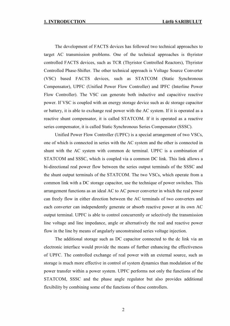
The development of FACTS devices has followed two technical approaches to
target AC transmission problems. One of the technical approaches is thyristor
controlled FACTS devices, such as TCR (Thyristor Controlled Reactors), Thyristor
Controlled Phase-Shifter. The other technical approach is Voltage Source Converter
(VSC) based FACTS devices, such as STATCOM (Static Synchronous
Compensator), UPFC (Unified Power Flow Controller) and IPFC (Interline Power
Flow Controller). The VSC can generate both inductive and capacitive reactive
power. If VSC is coupled with an energy storage device such as dc storage capacitor
or battery, it is able to exchange real power with the AC system. If it is operated as a
reactive shunt compensator, it is called STATCOM. If it is operated as a reactive
series compensator, it is called Static Synchronous Series Compensator (SSSC).
Unified Power Flow Controller (UPFC) is a special arrangement of two VSCs,
one of which is connected in series with the AC system and the other is connected in
shunt with the AC system with common dc terminal. UPFC is a combination of
STATCOM and SSSC, which is coupled via a common DC link. This link allows a
bi-directional real power flow between the series output terminals of the SSSC and
the shunt output terminals of the STATCOM. The two VSCs, which operate from a
common link with a DC storage capacitor, use the technique of power switches. This
arrangement functions as an ideal AC to AC power converter in which the real power
can freely flow in either direction between the AC terminals of two converters and
each converter can independently generate or absorb reactive power at its own AC
output terminal. UPFC is able to control concurrently or selectively the transmission
line voltage and line impedance, angle or alternatively the real and reactive power
flow in the line by means of angularly unconstrained series voltage injection.
The additional storage such as DC capacitor connected to the dc link via an
electronic interface would provide the means of further enhancing the effectiveness
of UPFC. The controlled exchange of real power with an external source, such as
storage is much more effective in control of system dynamics than modulation of the
power transfer within a power system. UPFC performs not only the functions of the
STATCOM, SSSC and the phase angle regulator but also provides additional
flexibility by combining some of the functions of these controllers.

1. INTRODUCTION Lütfü SARIBULUT
3
The aim of this research is to examine the performance of different controllers
for UPFC by using PSCAD/EMTDC program. In general, the control strategy of
UPFC should have preferably the following attributes:
• The steady state objectives (i.e. real and reactive power flows) should be readily
achievable by setting the references of the controllers.
• The dynamic and transient stability improvement by using appropriate controller
references.
To simplify the design procedure, we carry out the design for the series and the
shunt branches separately. The design has to be validated when the various
subsystems are integrated. The design tasks are given in the following.
• Series voltage control: The power flow will be controlled by using the series
voltage injection.
• Shunt voltage control: The controlling of the sending end bus voltage and the
regulating of the DC side capacitor voltage will be controlled by using the reactive.
Figure 1. 1 The test system used in this thesis
The report of the work done is organized as follows:
After this introductory chapter, the literature surveys associated with UPFC are
given in chapter 2.

1. INTRODUCTION Lütfü SARIBULUT
4
The chapter 3 gives a brief overview of the FACTS devices. The general
definition and operation of FACTS devices, basic control functions and
characteristics of UPFC are given in this chapter.
The chapter 4 discusses the proposed control strategy and the developed
controllers. The power flow in the line is clarified as mathematical equations, and the
effects of UPFC are mentioned on power flow. The general controllers (P, PI and
PID) are explained and developed fuzzy controller is examined.
The chapter 5 presents the actualizing the proposed UPFC model and its
controllers in simulink part by using PSCAD/EMTDC program.
The chapter 6 discusses the simulation results on the test system for different
cases.
The chapter 7 presents the conclusions. Adequate references are provided at the
end of this chapter.
1.2 Conclusion
The general outlines of FACTS devices are discussed in this chapter. The outline
of UPFC and the organization of thesis are given.
2. LITERATURE SURVEY Lütfü SARIBULUT
5
2. LITERATURE SURVEY
In this chapter a literature survey of UPFC operation, modeling and control
will be studied.
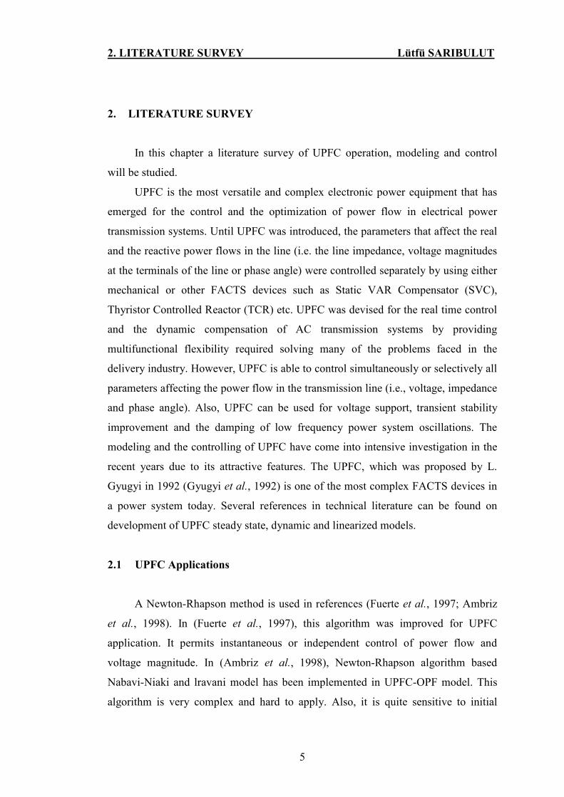
UPFC is the most versatile and complex electronic power equipment that has
emerged for the control and the optimization of power flow in electrical power
transmission systems. Until UPFC was introduced, the parameters that affect the real
and the reactive power flows in the line (i.e. the line impedance, voltage magnitudes
at the terminals of the line or phase angle) were controlled separately by using either
mechanical or other FACTS devices such as Static VAR Compensator (SVC),
Thyristor Controlled Reactor (TCR) etc. UPFC was devised for the real time control
and the dynamic compensation of AC transmission systems by providing
multifunctional flexibility required solving many of the problems faced in the
delivery industry. However, UPFC is able to control simultaneously or selectively all
parameters affecting the power flow in the transmission line (i.e., voltage, impedance
and phase angle). Also, UPFC can be used for voltage support, transient stability
improvement and the damping of low frequency power system oscillations. The
modeling and the controlling of UPFC have come into intensive investigation in the
recent years due to its attractive features. The UPFC, which was proposed by L.
Gyugyi in 1992 (Gyugyi et al., 1992) is one of the most complex FACTS devices in
a power system today. Several references in technical literature can be found on
development of UPFC steady state, dynamic and linearized models.
2.1 UPFC Applications
A Newton-Rhapson method is used in references (Fuerte et al., 1997; Ambriz
et al., 1998). In (Fuerte et al., 1997), this algorithm was improved for UPFC
application. It permits instantaneous or independent control of power flow and
voltage magnitude. In (Ambriz et al., 1998), Newton-Rhapson algorithm based
Nabavi-Niaki and lravani model has been implemented in UPFC-OPF model. This
algorithm is very complex and hard to apply. Also, it is quite sensitive to initial

2. LITERATURE SURVEY Lütfü SARIBULUT
6
condition settings. The order of the Jacobian matrix is increased significantly in the
iterative procedure. The selection of suitable initial conditions can solve the
oscillations of power system dynamics.
In references (Lo K.L et al., 1998; Nabavi-Niaki et al., 1996; Xu et al., 2004),
the steady state model, which is necessary for the analysis of the power flow
operation of device embedded in a power system, is preferred. In (Lo K.L et al.,
1998), Ann based direct control algorithm method is used to compare the simulation
results with steady state model. UPFC is modeled as a voltage source in series with
line reactance, and the mathematical calculation is incorporated with Jacobian
Matrix. The model is simple and helpful at understanding the impact of UPFC in the
power system. However, the amplitude modulation and phase angle control signals
of the series VSC have to be adjusted manually in order to find the desired load flow
solution.
In reference (Papic et al., 1997), the basic control method is used. It consists of
two control mechanism. One of them is real and reactive power flow control
mechanism and the other is sending end bus voltage and DC voltage magnitude
control mechanism. The vector-control approach is one of the most used control
scheme. It is proposed by Schauder and Metha in 1993 (Schauder et al., 1993). The
decoupled control of the real and the reactive powers can be applied easily in this
method and it is suitable for UPFC application. The decoupled control can be
achieved in this scheme by changing the three-phase balanced system into a
synchronously rotating orthogonal system (DQ transform). The D-axis of
synchronously rotating orthogonal system corresponds with the instantaneous
voltage vector and the Q-axis is orthogonal to it. The D-axis current component
coincides with the instantaneous real power and the Q-axis current coincides with the
reactive power in this coordinate system. This control scheme can be applied both for
series and shunt converters control in references (Yonggao et al.; 2005, Qing et al.,
1996; Fujita et al., 2006). Proportional-Integral (PI) controller is used to get dynamic
values close to their reference values. The sending end bus voltage magnitude and
the dc link voltage are measured to take reference values for components of system

2. LITERATURE SURVEY Lütfü SARIBULUT
7
current in references (Schauder et al., 1993; Yonggao et al. 2005; Padiyar et al.1998;
Liu et al.2005). This control method is simple and easy to implement.
Another approach is automatic power flow method (Kannan et al.2004). The
synchronously-rotating orthogonal system method is used in this method in the same
way as basic control method. There are some differences between the basic control
method and the automatic power flow method. In the basic control method, shunt and
series converters of current decompose into two components while in the automatic
power flow, the sending and the receiving buses voltage decompose into two
components. The sending end voltage and the dc capacitor voltage are measured to
take reference value of shunt converter, and the line real and reactive powers are
measured to take references of series converter (Kannan et al.2004; Hosseini et al.
2004; Zhu et al. 2005; Aihong et al. 2005). In order to get the desired result, the
reference value of system dynamics must be pre-specified (i.e. reference real and
reactive power value, dc capacitance reference value... etc).
The dynamic model of UPFC can be found in references (Uzunovic et al.
1999; Sen et al. 1998; Zhou et al. 2004; Nguyen et al. 2004). Two voltage sources
are used in this model. One of the voltage sources is connected in series and the other
is connected in shunt with the power network to represent the series and shunt VSCs.
Both voltage sources are modeled to inject voltages to power system with respect to
required power for the system and the voltage sources. In reference (Kalyani et al.
2003), the DC link capacitor and the sending end dynamics are used by shunt voltage
source to regulate the dc link voltage and the sending end bus voltage. In reference
(Nguyen et al. 2004), the dynamic model is used for Dynamic Voltage Restorer
(DVR). One of the dynamic models of references (Kannan et al.2004; Kalyani et al.
2003; Nguyen et al. 2004) will be used in this thesis.
The linearized model of UPFC applications is practical for small signal
analysis and damping controller design. The linearized model of UPFC can be found
in references (Wang et al.1999; Smith et al. 1997). In reference (Wang et al.1999)
the DC link dynamics do not contain, and in reference (Smith et al. 1997) the
sending and receiving buses of UPFC are also assumed as generator terminal buses
when the model derived.

2. LITERATURE SURVEY Lütfü SARIBULUT
8
Other control methods are current injection method, Hysteresis control method
and the non-linear control method. Some of the FACTS devices have been designed
by using some of these techniques as UPFC in reference (Son et al 2004; Meng et al.
2000; Sutanto et al. 2000; Green et al. 1989; Lu et al. 1997).
As another approach, fuzzy controller and Neural-Network based controller are
used with several control methods in UPFC (Eldamaty et al. 2005; Orizondo et al.
2006; Ma et al. 2000; Venayagamoorthy et al. 2005; Mishra et al. 2006). The fuzzy
controller is attractive for several control method, because it does not require the
mathematical model of the system under study conditions. It can cover wider range
of operating conditions, and is simple to implement. The fuzzy models are created by
using Sugeno Inference System and used in the series control mechanism of UPFC in
this thesis (Eldamaty et al. 2005). Fuzzy is used in the power frequency model of
UPFC in reference (Mok et al. 2000). PI and fuzzy controller are used together in the
current injection model in references (Orizondo et al. 2006; Ma et al. 2000).
Likewise, the fuzzy controller will be used with the PI controller in this thesis.
The objective of this thesis is to develop a UPFC model by using
PSCAD/EMTDC program, to design its controls mechanism with several controllers,
and to make performance analysis of these controllers.
2.2 Conclusion
The basic operation modes of shunt and series parts are given in this chapter. In
the next subsection, the application of UPFC is explained by classified according to
control methods.

3. FLEXIBLE AC TRANSMISSION SYSTEM Lütfü SARIBULUT
9
3. FLEXIBLE AC TRANSMISSION SYSTEM
3.1 Introduction to FACTS
FACTS technology is used extensively to enhance the controllability and the
capability of power transfer in the AC systems. FACTS involve conversion or
switching power electronics wide-range megawatts relatively.
The power electronics and the switching technology have been rapidly growing
area for a wide range of needs at the end-user side in two decades. The electricity is
an incredible form of energy that can be converted to many different forms of
energy, and it is used to bring new technologies for the humans. The power
conditioning technology is used by customers under the term of power quality when
the custom power technology was complemented.
Nowadays, large power demands have been provided on the transmission
network, and these demands will continue to rise because of the increasing number
of factories and the high competition among utilities. The increased demands on the
transmissions, the absence of the long term planning, and the need to provide the
open access to generating companies and the customers have created the tendencies
toward less security, and reduced the quality of the supply. FACTS technology is
essential to alleviate some problems, but not all of them. It enables utilities to get
more services from the transmission facilities and to enhance the power system
reliability.
FACTS technology offers new opportunities to control the power and to
enhance the utility of present network and the systems, as well as new and upgraded
lines. The established system can be controlled at reasonable cost by increasing the
capacity of transmission lines.
FACTS devices give facilities to the controllers that are able to control the
interrelated parameters, which govern the operation of transmission systems
including series and shunt impedance, current, voltage, phase angle and the damping
oscillations at various frequencies below the rated frequency. These constraints
cannot be overcome while the required system reliability is maintained by

3. FLEXIBLE AC TRANSMISSION SYSTEM Lütfü SARIBULUT
10
mechanical means without lowering the usable transmission capacity. By providing
added flexibility, FACTS devices are able to carry the line power to nominal ratings.
It must be emphasized that FACTS is an applicable technology to implement in the
companies and industries.
Some of the power electronic controllers are introduced to the technical
community by Narian G. Hingorani (Hingorani et al. 1993) before introducing
FACTS concept. However, the unique aspect of FACTS technology is that this
umbrella concept reveals the large potential opportunity for the power electronics
technology to enhance the value of power system ratings.
3.2 FACTS Controllers
In general, FACTS devices can be divided into four categories.
• Series controllers
• Shunt controllers
• Combined series-series controllers
• Combined series-shunt controllers
3.2.1 Series Controllers
The control concept of series compensators is related to how the maximal
power is transmitted in the line and the steady state power transmission is attainable.
These are related to the voltage stability and the power oscillation damping. The
series controllers inject the voltage in series with the line. The reactive power is
supplied or consumed by series controller only as long as the voltage is quadrature
with the line current. Also, other different phases will involve the utilization of the
real power as well. The some of series controllers are listed below.
• Thyristor Controlled Series Capacitor (TCSC)
• Thyristor Switched Series Capacitor (TSSC)
• GTO Thyristor-Controlled Series Capacitor (GCSC)

3. FLEXIBLE AC TRANSMISSION SYSTEM Lütfü SARIBULUT
11
• Static Synchronous Series Compensators (SSSC): The VSC based series
compensator is known as Static Synchronous Series Compensator (SSSC). It was
proposed by Gyugyi in 1989. SSSC represents an alternative like synchronous
voltage source in the series line compensation. It is operated as series compensator
without an external electric energy source, and its output voltage is controllable and
is in quadrature with the line current. It is implemented by thyristor-based VSC and
used to provide the controllable series compensation, seen in Figure 3.1. When
SSSC is operated with an appropriate dc power supply at its input terminals, this
compensator is used in generators and solid-state switching converters. When SSSC
is coupled with an energy storage capacitor, it can be used only to generate or absorb
the reactive power from the system. The SSSC is connected to the three-phase
transmission line with series VSC through a coupling transformer.
The power flow can be increased in the line by inserting an additional series
capacitive reactance. As a result of this, the effective line impedance is decreased.
The power flow can be also decreased by inserting an additional inductive reactance.
Consequently, the effective reactance is increased. It is employed to increase or to
decrease the overall reactive voltage drop across the line. Thus, it is modeled as an
inductive or a capacitive reactance in series with the transmission line. This variable
reactance influences the power flow in the transmission line. The voltage, which is in
phase with the line current, meets the losses in the converter.
Figure 3. 1 Basic scheme of SSSC
The battery storage or capacitance can also be connected with the series
controller to inject the series voltage with variable angle in the line. Without an extra

3. FLEXIBLE AC TRANSMISSION SYSTEM Lütfü SARIBULUT
12
energy source, SSSC can inject only variable voltage, which is 90o leading or
lagging the current.
3.2.2 Shunt Controllers
The shunt controllers may be seen as variable impedance, variable source, or
a combination of these variables. The main operation principle of shunt controllers is
to inject the current to the line from the connection point of the system. The shunt
controller supplies or consumes only variable reactive power when the injected
current is in quadrature with the line voltage. The shunt controller supplies or
consumes real power when there is any other phase relationship with the line voltage.
The some of shunt controllers are listed below.
• Static Synchronous Generator (SSG)
• Static VAR Compensator (SVC)
• Thyristor Controlled Reactor (TCR)
• Static Synchronous Compensator (STATCOM): A static synchronous compensator
(STATCOM) is a shunt-connected reactive power compensation device that is
capable of generating or absorbing reactive power whose output can be varied to
control specific parameters of an electric power system. In general, it is a solid-state
switching converter, capable of generating or absorbing independently controllable
real and reactive power at its output terminals when it is fed from an energy source
or energy. Storage device is coupled at STATCOM input terminals.
STATCOM system is comprised of three main parts: a voltage source
converter, a coupling reactor or a step-up transformer, and a controller. The
STATCOM is connected to the power networks at a point of common coupling. All
required voltages and currents are measured and fed into the controller in order to be
compared with the references. The feedback control is used as outputs by switching
signals to drive the main semiconductor switches of the power converter accordingly.
The magnitude and phase of the VSC output voltage is controlled by the turn-
on/turn-off of semiconductor switches in the VSC.

3. FLEXIBLE AC TRANSMISSION SYSTEM Lütfü SARIBULUT
13
Figure 3.2 shows a simple Figure of STATCOM based on a VSC. The reactive
power exchange between the converter and the AC system can be controlled by
varying the amplitude of the three-phase output voltage of the converter. That is, if
the amplitude of the output voltage is increased above that of the utility bus voltage,
then the current flows through the reactance from the converter to the AC system and
the converter generates capacitive reactive power for the AC system. If the amplitude
of the output voltage is decreased below the utility bus voltage, then the current
flows from the AC system to the converter, and the converter absorbs inductive
reactive power from the AC system. If the output voltage is equal to the AC system
voltage, the reactive power exchange is zero.
Similarly, the real power exchange between the converter and the AC system
can be controlled by adjusting the phase shift between the converter output voltage
and the AC system voltage. That is, the converter can supply real power to the AC
system from its dc energy storage if the converter output voltage is made to lead the
AC system voltage. On the other hand, it can absorb real power from the AC system
for dc energy if its voltage lags the AC system voltage.
Figure 3. 2 Basic scheme of STATCOM
Although reactive power is internally generated by the action of converter
switches, it is still necessary to have a dc capacitor connected across the input
terminals of the converter. The need for the capacitor is primarily to provide a
circulating current path as well as a voltage source. The magnitude of the capacitor is
not important, but generally it is chosen such that the dc voltage across its terminals
3. FLEXIBLE AC TRANSMISSION SYSTEM Lütfü SARIBULUT
14
remains fairly constant so that it doesn't contribute to the ripples in the dc current.
This results in slight fluctuations in the output power of the converter.
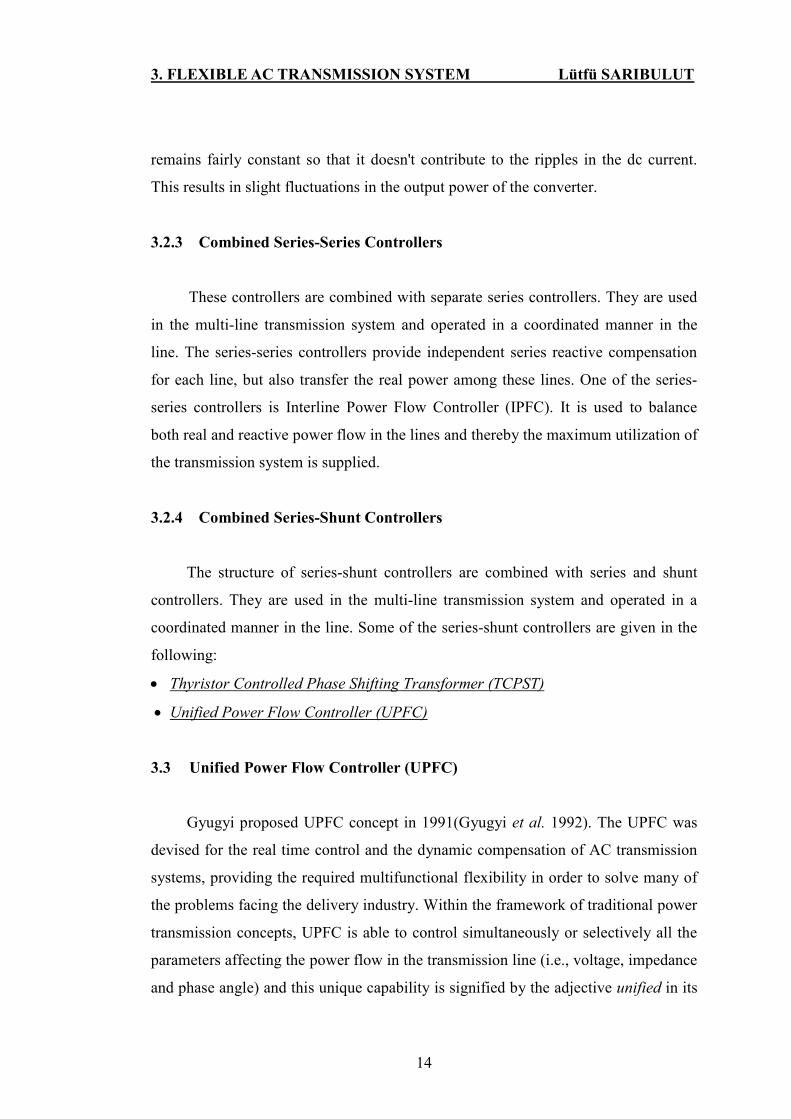
3.2.3 Combined Series-Series Controllers
These controllers are combined with separate series controllers. They are used
in the multi-line transmission system and operated in a coordinated manner in the
line. The series-series controllers provide independent series reactive compensation
for each line, but also transfer the real power among these lines. One of the series-
series controllers is Interline Power Flow Controller (IPFC). It is used to balance
both real and reactive power flow in the lines and thereby the maximum utilization of
the transmission system is supplied.
3.2.4 Combined Series-Shunt Controllers
The structure of series-shunt controllers are combined with series and shunt
controllers. They are used in the multi-line transmission system and operated in a
coordinated manner in the line. Some of the series-shunt controllers are given in the
following:
• Thyristor Controlled Phase Shifting Transformer (TCPST)
• Unified Power Flow Controller (UPFC)
3.3 Unified Power Flow Controller (UPFC)
Gyugyi proposed UPFC concept in 1991(Gyugyi et al. 1992). The UPFC was
devised for the real time control and the dynamic compensation of AC transmission
systems, providing the required multifunctional flexibility in order to solve many of
the problems facing the delivery industry. Within the framework of traditional power
transmission concepts, UPFC is able to control simultaneously or selectively all the
parameters affecting the power flow in the transmission line (i.e., voltage, impedance
and phase angle) and this unique capability is signified by the adjective unified in its

3. FLEXIBLE AC TRANSMISSION SYSTEM Lütfü SARIBULUT
15
name. The UPFC is a combination of STATCOM and a SSSC, which are coupled via
a common DC link. This link allows a bi-directional flow of real power flow between
the shunt output terminals of the STATCOM and the series input terminals of the
SSSC. This real power is controlled to provide concurrent real and reactive series
compensation without an external electric energy source. The active power for the
series converter is obtained from the line via the shunt converter STATCOM. It is
also used for voltage phase and amplitude to control its reactive power. This is a
complete controller for controlling the active and reactive power through the line, as
well as line voltage controller. The details circuit of UPFC is shown in Figure 3.3.
Additional storage, such as capacitor or DC voltage source connected to the dc link
via an electronic interface, would provide the means of enhancing the effectiveness
of UPFC.
3.3.1 Circuit Arrangement
The general definition of UPFC is combined with two converters and they are
considered as a VSC in the applications. The Gate Turn-Off (GTO) thyristor valves
are used in the VSC, as illustrated in the Figure 3.3. They are labeled as Converter A
and Converter B and coupled back to back a common dc link provided by a dc
storage capacitor. This arrangement functions as an AC to AC power converter. The
real power can flow bi-directionally between the AC terminals of the converters, and
each converter can generate or absorb independently reactive power at its AC output
terminal.
Figure 3. 3 Basic circuit of UPFC

3. FLEXIBLE AC TRANSMISSION SYSTEM Lütfü SARIBULUT
16
3.3.2 Operation Principle of UPFC
The AC voltage Vpq is provided by converter B, and it is the main function of
UPFC. The voltage Vpq is injected with controllable magnitude Vpq (0≤Vpq≤Vpqmax)
and phase angle θ (0≤ θ ≤360) at the power frequency. It is in series with the line
via an insertion transformer. The injected voltage is thought as a synchronous voltage
source. The transmission line current flows through the output terminal of series
VSC insertion transformer and the power exchange with the AC system is bring
about in output terminal of series VSC insertion transformer. The real power is
exchanged at the AC terminal of shunt converter and is converted as required dc
power. It appears as positive or negative real power demanded by the dc link. The
reactive power exchanged at the AC terminal is generated internally by the converter.
The converter A is to supply or absorb the real power from the system for
requirements of the converter B and the common dc link. Also, the converter A can
generate or absorb reactive power from the system according to bus voltage which
converter is connected to the system. Thus, when the reactive compensation is
required, it can provide to the system independently. There is a closed path for the
real power flow from the converter B during the series voltage injection to the line.
The required real and reactive power of the system is supplied or absorbed by the
converter B. Thus, the converter A can operate reactive power exchange with the line
independent from the reactive power exchange of the converter B. This means that
there is no continuous reactive power flow through the DC link in UPFC.
3.3.3 Control Functions of UPFC
The operation of UPFC depends on reactive shunt compensation, series
compensation and phase shifting. These functions and multiple control objectives can
be supplied by UPFC with by adding the injected voltage Vpq (with appropriate
amplitude and phase angle, to add the terminal voltage Vo). Using the phasor
representation, the basic UPFC power flow control functions are illustrated in Figure
3.4.

3. FLEXIBLE AC TRANSMISSION SYSTEM Lütfü SARIBULUT
17
• Terminal voltage regulation: It is shown in Figure 3.4 at (a).It is similar with a
transformer tap-changer.
Where Vo is the line voltage and V∆ (Vpq) is injected in-phase (or anti-phase) with
Vo.
• Series capacitor compensation: It is shown in Figure 3.4 at (b). Vc (Vpq) is in
quadrature with the line current I.
• Transmission angle regulation (phase shifting): It is shown in Figure 3.4 at (c).
Vσ (Vpq) is injected to Vo according to angular relationship with Vo. Therefore, the
desired phase shift (advance or retard) achieves without any change in magnitude.
• Multifunctional power flow control: It is shown in Figure 3.4 at (d) where Vpq= V∆
+Vσ+Vo. It is accomplished by instantaneous terminal voltage regulation, series
capacitive compensation, and phase shifting.
With suitable electronic controls, UPFC can cause the series-injected voltage
vector to vary rapidly and continuously in magnitude or angle as desired. The control
of UPFC is based upon the vector-control approach proposed by Schauder and Mehta
for advanced static VAR compensators (i.e., for STATCOM) in 1991.
The symbols V and I are used as voltage and current vectors. These vectors are
not stationary. According to the changing of the phase values, it moves around a
fixed point in the plane. It describes various trajectories which become circles. For
the purpose of power control, it is useful to view these vectors in an orthogonal
coordinate system with D and Q axes such that the D axis is always coincident with
the instantaneous voltage vector V, and the Q axis is in quadrature with it. In this
coordinate system, the D-axis current component id accounts for the instantaneous
real power, and Q-axis current component iq for reactive power. Under balanced
steady state condition, the D-axis and Q-axis components of the voltage and current
vector are constant quantities. In this thesis, D-axis and Q-axis components of the
voltage will be used in the control mechanism of series converter.

3. FLEXIBLE AC TRANSMISSION SYSTEM Lütfü SARIBULUT
18
(a) Voltage Regulation
VC
Vo
Vo+Vc
b) Series Compensation
(c) Phase Angle Regulation
V
σVo Vo+Vσ
V
σ
Vo
Vo+V + V+Vcσ
∆
Vo
VO
VPQ
∆
(d) Multi-Function
Vo+ V∆
Vo
Figure 3. 4 Basic UPFC control functions
Operation modes of UPFC are classified in two groups. One of these groups is
for shunt converter and the other is for series converter. These modes are given in the
following.
3.3.4 Shunt Converter
The operation principle of shunt converter is used to draw a controlled current
from the line. This current is created by calculating both the requirement of the real
power for the series converter and the reactive power to set its quantity for any
desired reference level (inductive or capacitive) within the capability of the
converter. Reactive compensation control mode of shunt converter is very similar to
those commonly employed on conventional SVCs.
• VAR Control Method: According to the system situation, the reference input
signal is an inductive or capacitive VAR request. The controller takes the reactive
reference to translate into a corresponding shunt current request and adjusts the

3. FLEXIBLE AC TRANSMISSION SYSTEM Lütfü SARIBULUT
19
gating of the converter to establish the desired current. A feedback signal
representing the dc bus voltage and the current feedback signals is taken by the
controller obtained from current transformers (CTs) and Vdc is also required.
• Automatic Voltage Control Mode. The shunt reactive current of converter is
automatically regulated to keep the transmission line voltage at the point of shunt
converter connected to a reference value.
3.3.5 Series Converter
The series converter injects the voltage series with the line to control the
magnitude and angle of the line voltage. The purpose of voltage injection is always
affecting the direction of power flow in the line. The real value of injected voltage
can be determined in different ways in the following.
• Direct Voltage Injection Model. According to the reference input, the converter
simply generates a voltage vector at required magnitude and phase angle. A special
situation of the model is that when the injected voltage is kept in quadrature with the
line current, only the reactive series compensation is provided.
• Phase Angle Shifter Emulation Model: The voltage is injected at the amount of the
angle which is specified by the reference input so that the phase angle of line voltage
is shifted simply.
• Line Impedance Emulation. The voltage is injected proportion with the line
current by series converter. Thus, the series transformer is seen as impedance when
viewed from the line. The reference input is selected by desired impedance and in
general it may be complex impedance with resistive and reactive components of
either polarity. There must be taken care in this mode to avoid values of negative
resistance or capacitive reactance because of resonance or instability situation.
• Automatic Power Flow Control Mode. In this control mode, the vector control
system determines the voltage injected as series automatically and continuously by a
vector control system to ensure that the desired real power (P) and reactive power
(Q) are maintained despite system changes. Also, this mode can be used dynamically
for system oscillation damping.

3. FLEXIBLE AC TRANSMISSION SYSTEM Lütfü SARIBULUT
20
3.3.6 Power Flow Control with UPFC
The performance of UPFC is demonstrated on the real and reactive power flow
by keeping the sending end and receiving end bus voltages constant (at 1.0 per unit
(pu) magnitude, and a fixed phase angle). The automatic power flow control mode is
preferred when the real and reactive power of line is kept at given reference values.
The important point is that the power flow should be changed much more gradually
and carefully in the real system in order to avoid possible dynamic disturbances in
the system.
3.3.7 Operation under Line Faults
According to the location of the system fault, the line current can reach at
maximum ratings or exceed the converter rating during faults. The current of the
compensated line flows through the series converter of UPFC. When the fault
condition is sensed by the series controller of UPFC, it enters the bypass-operating
mode immediately. In this mode, the value of the injected voltage and the line
current would be reduced to zero. The series converter would be bypassed by the
series converter valve, reconfigured electronically for terminal shorting or through a
separate high current thyristor valve. After fault condition is cleared by series control
mechanism, the mechanical bypass breaker would also be employed normally.
3.4 Conclusion
In this chapter, basic concepts of FACT devices are given. These devices are
divided in four groups and these groups are explained with given examples.
STATCOM and SSSC, two parts of UPFC are studied in this chapter. Later, basic
concepts of UPFC are given in terms of its circuit arrangement, operation principles,
basic control functions and structure. The behavior of UPFC facing faults in the
system is mentioned in this chapter.

4. CONTROLLERS OF UPFC Lütfü SARIBULUT
21
4. CONTROLLERS FOR UPFC
4.1 Basic Concepts
UPFC is combined with STATCOM and SSSC. These parts are coupled
together with common DC link (capacitor) to allow the real power flow between the
series and shunt converter output terminals bi-directionally, and to provide real and
reactive line compensation without an external energy source. UPFC is able to
control the series voltage injection ( V θ∆ ) by the means of unconstrained angle.
The transmission line with UPFC, which is extended in AC transmission network, is
shown in the Figure 4.1.
Vs δr
V
V θ∆
Figure 4. 1 AC Transmission network with UPFC
The voltage represented by a phasor V φ∆ is injected by SSSC in series with
the transmission line. The magnitude of V∆ is limited from 0 to 0.5 pu and its angle
φ is constrained from 0° to 360° (Song et al.1999). This voltage can be added
vectorally to the sending end voltage (Vs δ ), and the transmission line voltage can be
seen asVs V φ+ ∆ , as shown by the Figure 4.1. Thus, the sending end voltage (ef
V )
is effectively on the line voltage. According to this situation, UPFC affects both the
magnitude and the phase angle of the line voltage on the transmission line. Hence, it
is reasonable to expect its ability to control the transmittable real and reactive power
demand by varying the magnitude and phase angle of the line at any given
transmission phase angle between the sending and receiving end voltages.

4. CONTROLLERS OF UPFC Lütfü SARIBULUT
22
The transmitted real (Po) and reactive power (Qo) of the transmission above
without UPFC (from sending to receiving end bus) are given by the expression.
sin( )
( )
V Vs r
Po
X
δδ = (4.1)
( cos( ) )
Q ( )o
V V Vr s r
X
δδ
−= (4.2)
The real and reactive power flow of the transmission line at the receiving end
with UPFC is given by following equations (4.1) and (4.2).
Real power of the system with UPFC:
sin( ) sin( )P ( , )=
V V VVs r r
X
δ φδ φ
+∆ (4.3)
From equation (4.1) and (4.3)
sin( )P ( , )= ( )
VVr
Po X
φδ φ δ
∆+ (4.4)
( , ) ( )sin( )
P P Xo
VVr
δ φ δφ
−∆ = (4.5)
Reactive power of the system with UPFC:
( cos( ) cos( ) )Q ( , )=
V V V Vr s r
X
δ φδ φ
+∆ − (4.6)
From equation (4.2) and (4.6)
cos( )Q ( , )=Q ( , )= ( )
V VrQo X
φδ φ δ φ δ
∆+ (4.7)
cos( ) ( ( , ) )X
V Q Qo Vr
φ δ φ∆ = − (4.8)
To provide the required real and reactive power, the magnitude and phase angle
of the series-injected voltage from equation (4.5) and (4.8) are given by following
equations:
2 2( ( , ) ) ( ( , ) )
XV P P Q Qo o
Vrδ φ δ φ∆ = − + − (4.9)
Phase angle of injected voltage,
( , )tan( )
( , )
P Poa
Q Qo
δ φφ
δ φ
−=
− (4.10)

4. CONTROLLERS OF UPFC Lütfü SARIBULUT
23
The equations (4.9) and (4.10) give information about V∆ and the phase angle
φ of series-injected voltage to get the demanded real and reactive power by the
system within the specified range defined by the maximum limit of injected V∆ . The
phasor diagram based on the mathematical derivation above, which gives the
magnitude and phase angle of injected voltage to meet the demand of real and
reactive power of the system, is obtained, as shown in Figure 4.2 (Song et al. 1999).
V∆
Figure 4. 2 The transmittable power versus phase angle (δ ) of UPFC
The transmittable of the real and reactive power will be specified by the
maximum limit of injected V∆ .The wide range of controlling the transmitted power
independent from the transmission angle (δ ) indicates not only superior capability of
UPFC in power flow applications, but also promises powerful capacity for transient
stability improvement and power oscillation damping. The controllable of the real
power (P) and the reactive power (Q) at the receiving end between any transmission
angle (δ ) can be seen in the following mathematical equations.
max max( ) ( , ) ( )
V VP P Po oX X
δ δ φ δ∆ ∆
− ≤ ≤ + (4.11)
max max( ) ( , ) ( )
V VQ Q Qo oX X
δ δ φ δ∆ ∆
− ≤ ≤ + (4.12)
The powerful capabilities of UPFC are discussed above in terms of
conventional transmission control concepts. It can be integrated into a generalized
power flow controller that is able to maintain prescribed controllable real power and
reactive power Q in the line (Song et al. 1999)

4. CONTROLLERS OF UPFC Lütfü SARIBULUT
24
4.2 Controlling the Real and Reactive Power Flow
Considering the equations (4.9) and (4.10), the real and reactive power change
from the uncompensated values ( )oP δ and ( )
oQ δ as a function of the magnitude and
the phase angle of the injected voltage V∆ . As the angle φ is an unrestricted
variable 0 00 360φ< < , the attainable boundary of the control region for ( , )P δ φ
and ( , )Q δ φ is obtained from a complete rotation of the phasor V∆ with its
maximum maxV∆ .
The equations mentioned above verify that this control region is a circle with a
center defined by the coordinates defined by ( )oP δ and ( )
oQ δ , and the radius is
given by following equation:
2 2 2( ( , ) ( )) ( ( , ) ( )) ( )
VP P Q Q
o o Xδ φ δ δ φ δ
∆− + − = (4.13)
The circular control regions are defined by the equation (4.13). These regions
are shown in the Figure 4.3 and 4.4. The center of these circuses are ( )oP δ and
( )o
Q δ at angles 0°δ = , 30°δ = , 60°δ = and 90°δ = respectively. The focus of
the centers are indicated by the + sign as δ varies between 0° and90° .
When the transmission line angle (δ ) and amplitude V∆ are zero, the real
power ( )oP δ and reactive power ( )
oQ δ flows are zero. According to this situation,
the system is at standstill at the origin of the P and Q coordinates. It is illustrated as a
case in the Figure 4.3. The circle around the origin of the plane is the locus of the
corresponding Q and P values (at receiving end). It is obtained as the voltage phasor
V∆ which is rotated around itself by a full revolution (0 00 360φ< < ) with its
maximum value maxV∆ .The boundary of the circle in the (P, Q) plane shows all P and
Q values obtainable with UPFC in accordance with given rating. The UPFC with the
specific voltage rating of 0.5 pu is able to obtain 0.5 pu power flowing into either
direction without imposing any additional reactive power demanded on either the

4. CONTROLLERS OF UPFC Lütfü SARIBULUT
25
sending or the receiving end bus, as seen from Figure 4.3 and 4.4.
max()
Pδ
0V∆
=
+
min()
Pδ
+++++++++++
++++
maxPminP
minQ
maxQ
00δ =
,Po Qo
00δ =
max( )P δ
0V∆
=
+
min( )P δ
+++++++++++
++++
maxP
minP
030δ =
minQ
maxQ
00δ =
,Po Qo
Figure 4. 3 Control region of line power with a UPFC for 0°δ = and 30°δ =
Q
0.5
P
1 1.5
0.5
1
-0.5
max( )P δ
0V∆
=
+
-1
-1,5
min()
Pδ
+++++++++++
++++
Controllable region
maxPminP
060δ =
-0.5
minQ
maxQ
060δ =
,Po Qo
0
-1
00δ =
090δ =
Q
0.5
P
1 1.5
0.5
1
-0.5
max( )P δ
0V∆ =
+
-1
-1,5
min( )P δ
+++++++++++
++++
Controllable region
maxP
minP
090δ =
-0.5
minQ
maxQ060δ =
,Po Qo
0
-1
00δ =
090δ =
Figure 4. 4 Control region of line power with UPFC for 60°δ = and 90°δ =
The skills of UPFC demonstrated in the Figures 4.3 and 4.4 shows the
capability of controlling the real and reactive power flow independently at any
transmission angle provide a powerful tool for AC transmission control.
4.3 Control Methods Used in Shunt and Series Converter
The control methods of these converters are studied individually by taking into
account that UPFC is a combination of shunt and series converters which are coupled
via a common DC link (capacitor). The operating characteristics of UPFC exhibit

4. CONTROLLERS OF UPFC Lütfü SARIBULUT
26
excellent performance because of its unique ability to inject an AC compensating
voltage vector V φ∆ with arbitrary magnitude and angle in series with the
transmission line within specified equipment's maximum rating limits. Several
control methods are discussed in chapter 2. The basic control, automatic control and
dynamic control methods based on three-phase balanced system into a synchronously
rotating orthogonal system (DQ transform) are used most commonly in the control
mechanism of UPFC. A dynamic control method is studied for each converter
individually in this thesis. The structures of converters used in shunt and series parts
of UPFC are examined in detail Appendix A. The DQ transform is discussed with
details at Appendix B.
4.3.1 Control Method of Shunt Converter
The shunt converter operates to draw a controlled current from the
transmission line for the following reasons;
• To keep the transmission line voltage at its reference value at the connection point
of the line by providing or absorbing reactive power.
• To maintain capacitance voltage level at its reference value on the DC link.
Before understanding the control mechanism of shunt converter, it is assumed
that there is no real power exchanged within the system in the steady state. Hence,
the DC source can be replaced by a capacitor. The real power is required to
compensate capacitor voltage. The energy requirement of this capacitor is very small
and this required instantaneous real power is provided by STATCOM in perfectly
balanced conditions. Therefore, the role of the capacitor is to provide energy storage
during transients, unbalanced operation and also to provide the reactive power to
keep the transmission line voltage at its reference value. The mathematical equation
of the reactive current entering the shunt converter is given as follow:
( )( )V Vs sh
Ishq jX
sh
−= (4.14)
The magnitude of the AC side voltage is s
V , the fundamental component of the

4. CONTROLLERS OF UPFC Lütfü SARIBULUT
27
switched voltage which is directly proportional to the DC bus voltage on the valve
side of the transformer is sh
V and the reactance of the shunt converter transformer
issh
X . The circuit is transformed to the AC network side. Thus, the turn ratio of
transformer does not appear in the calculations. In order to provide an output that it is
in phase with the system voltage, the steady-state real current should be zero. When
the firing of the shunt converter valves accomplishes the firing angle 0°, the steady-
state real current is going to be zero. According to this situation, some results are
obtained as follows:
When the firing of the valves is temporarily advanced, s
V would lead sh
V . The
real power is transferred from the capacitance to AC network and then the capacitor
voltage is reducing. When the firing is retarded from its steady state value, the real
power would be transferred from AC network into the capacitor. The firing angle
reverts to zero, when the required voltage is reached to provide the desired reactive
power. The charging or discharging of the capacitor voltage can enhance the transient
response time. Particularly, a large value of capacitance used in the shunt converter
causes large unbalances. It is desired situation sometimes, principally for design of
the STATCOM. It is used at the sub-transmission or distribution level that the
reactive power changes without the variation of the DC bus voltage. In the
STATCOM, which Pulse Width Modulation (PWM) is used, the reactive power can
be regulated with Sinusoidal Pulse Width Modulation (SPWM) controller and
selecting the proper modulation index without affecting the DC voltage. The study
principle of PWM is examined in details at Appendix C.
The real power is required to change the capacitor voltage. It can only be
achieved by a phase shifting between the shunt converter and AC system voltages.
Hence, the phase angle δ between the AC side voltage and fundamental component
of the switched voltage on the valve side of the transformer is changed to control the
DC capacitor voltage in this control mechanism. The angle in phase with the positive
sequence of the fundamental AC waveform is generated by using a Phase-Locked
Loop (PLL) which is locked to the phase of AC system voltages.

4. CONTROLLERS OF UPFC Lütfü SARIBULUT
28
The equations (4.3) and (4.6) point out the method to make a decoupled control
mechanism in which the reference of the real power *P does not affect the reference
of reactive power *
Q and vice-versa, if the transmission line is considered to be a
pure reactance with no losses. The quantity cos( )V φ∆ (direct axis) and the quantity
sin( )V φ∆ (quadrature axis) of the injected voltage vector can be considered as real
and imaginary components respectively. By using same equations, it can be deduced
that the Q component of the injected voltage affects only the real power flow and the
D component of the injected voltage affects only the reactive power flow in the line.
When voltage level of DC capacitor is dropped from its reference value, the
real power is required to restore its voltage at nominal level, and it is drawn from the
line. This shows that dc voltage level is signed to the required real power. Likewise,
bus voltage level, where the converter is connected, is signed to the required reactive
power (Kannan et al. 2004; Uzunovic et al. 1999; Kalyani et al 2003). Figure 4.5
shows the control mechanism of the shunt converter used in this thesis.
−+
puVsendpuVsend∆ Ki
Kps
+
_ _Order real power
_ _Order reactive power
*puVsend
α
puIVI
_Mod Function−+dcV
puVdc∆
KiKp
s+
*dcV
%
*_ _puVdc set value
Loop
PhaseLocked
recdaV
recdbV
recdcV
θ
sin( )IVI σSPWM
Controller
Firing
_Pulse of
Converter
_ _Sending End Voltage
−+
σ
Figure 4. 5 The control mechanism used in the shunt converter in thesis
Measured DC capacitor voltage level (Vdc) is divided to its reference value and
compared with its set value. Similarly, sending end bus voltage is measured in form
of pu (Vsendpu) and compared with its reference value. PI controller is used for
obtained err values to draw their reference values. Obtained signals are compared
with triangle carrier signal to produce pulses in the SPWM.

4. CONTROLLERS OF UPFC Lütfü SARIBULUT
29
4.3.2 Control Methods of Series Converter
The magnitude and phase angle of series-injected voltage is controlled by
series converter to provide the desired real and reactive power flow in the
transmission line. The control methods are studied mainly for the following reason to
supply the independent control for real and reactive power flow in the transmission
line. The magnitude and the phase angle of the injected voltage ( cos( )V wt φ∆ + ) for
any desirable real *
P and reactive power *Q are determined by using the equations
(4.9) and (4.10). From the equations (4.5) and (4.8), it is seen that the term
cos( )V wt φ∆ + denotes as a real power and the term sin( )V wt φ∆ + denotes as a
reactive power. In other word, the D component of the injected voltage affects the
real power flow and the Q component of the injected voltage affects the reactive
power flow in the line. The DQ transform is used in the control mechanism of SSSC
and it gives good results on controlling the real and reactive power flow in the line.
The real and reactive powers of system are measured and then compared with
their reference values in the control strategy of series converter generally (Kannan et
al. 2004; Zhou et al. 2004; Kalyani et al.2003). In reference (Nguyen et al. 1998),
the phase angle of the system voltage is found via PLL and compared with its
reference value. This technique is improved for Dynamic Voltage Restorer (DVR)
and used in series converter with adding new properties in this thesis is shown in
Figure 4.6.
Loop
PhaseLocked
recaV
recbV
reccV
θ
SPWM
Controller
Firing
_Pulse of
Converter
Re _ _ceiving End Voltage
sin( )θ
reca_refV
recc_refV
recb_refV A B C− −to
D Q O− −
recD_refV
recO_refV
recQ_refV
θ
*A B C− −to
D Q O− −
recDV
recOV
recQV*
Pref
Qref
+−
+−
+−A B C− −
to
D Q O− −
ref_AV
ref_CV
ref_BV
Figure 4. 6 The control mechanism used in the series converter in thesis

4. CONTROLLERS OF UPFC Lütfü SARIBULUT
30
The signal θ is obtained by PLL which tracks the voltage of the receiving end
voltage. It is used to produce sin( )θ for DQ transform. Hence, the reference signals
are obtained. The signals measured from receiving end voltage are transformed into a
synchronously rotating orthogonal system (DQ transform) by using ABC-to-DQ
block. These signals are compared with reference signals and the error signals are
obtained. These error signals are transformed from synchronously rotating
orthogonal system into three-phase balanced system again and utilized to generating
pulses for series converter.
4.4 Controllers Used in Performance Analysis of UPFC
The UPFC affects the power flow in the system. The controllers used in the
control mechanism of series and shunt converter perform significantly role on
affecting the power flow in the system. The types of controller are very important on
performance of UPFC. In literature, several controllers are improved and used in the
control mechanism of UPFC. Generally, PI and fuzzy controllers are used. The fuzzy
controller is improved and used in this thesis.
In many control applications, the feedback control is used. The benefits of this
control method are that it is possible to keep some physical quantity at a strict level
or change the value of the quantity, pressure, temperature etc, quickly and despite of
the disturbances that might occur. The basic requirement that a control system should
be able to fulfill is stability. This means that a controlled system should remain stable
in all circumstances. The Figure 4.7 shows the principal structure of feedback
control. The output signal must be followed the reference signal as precisely as
possible in the feedback control. We measure the output of the process and create an
error signal (me r y= − ). Error signal is an input signal for the controller. The
controller creates the control signal (based on the error signal) and controls the
process (actually the controller controls an actuator which controls the process).

4. CONTROLLERS OF UPFC Lütfü SARIBULUT
31
Controller
Re
_
ference
Signal r+−
_
Error
Variable e _
Control
Signal uProcess
_
Output
Signal y
Sensor
_ m
Measurement
Signal y
Figure 4. 7 Principal structure of feedback control
The proportional term (P) gives a system control input proportional with the
error. Using only P control gives a stationary error in all cases except when the
system control input is zero and the system process value equals the desired value.
The integral term (I) gives an addition from the sum of the previous errors to
the system control input. The summing of the error will continue until the system
process value equals the desired value and these results in no stationary error when
the reference is stable. The most common use of the I term is normally together with
the P term, called a PI controller. Using only the I term gives slow response and
often an oscillating system.
The derivative term (D) gives an addition from the rate of change in the error to
the system control input. A rapid change in the error will give an addition to the
system control input. This improves the response to a sudden change in the system
state or reference value. The D term is typically used with the P or PI as a PD or PID
controller. The D term essentially behaves as a high pass filter on the error signal.
Thus, easily introduces instability in a system and make it more sensitive to noise.
4.4.1 Proportional Controller (P)
In P-control, the output of the controller (control signal) is directly proportional
to the error signal. Simple P controller used in control mechanism is shown in Figure
4.8.
R +−E U ( )G s
Y
SensorMY
P
Figure 4. 7 Basic scheme of P Controller

4. CONTROLLERS OF UPFC Lütfü SARIBULUT
32
( )U K te
= (4.15)
From equation 4.15, K is controller’s gain. Often P-control is not enough to
make the output go to reference and there will be steady-state deviation.
4.4.2 Proportional Integral Controller (PI):
In PI-controller, there is another term in the controller equation shown in Figure
4.9.
R +−E U ( )G s
Y
SensorMY
PI
Figure 4. 8 Basic scheme of PI Controller
1
1( ( ) ( ) )t
OU K e t e t dt
T= + ∫ (4.16)
From equation 4.16, IT is integration time constant. If the controller is tuned to
be slow and IT is large, then the controller first acts like P-controller, but later the as
the integration starts to affect, the steady-state deviation goes slowly to zero. In PI-
control, the steady-state deviation will finally go to zero. If the controller is tuned to
be fast and IT is small, then both terms (P and I) affect the control signal all the way
from the beginning. The system becomes faster, but the output signal might oscillate.
4.4.3 Proportional Integral Derivative Controller (PID)
The equation of PID-controller has three terms. These are P, I and D-terms.
Simple PID controller used in control mechanism is shown in Figure 4.10.
R +−E U ( )G s
Y
SensorMY
PID
Figure 4. 9 Basic scheme of PID Controller

4. CONTROLLERS OF UPFC Lütfü SARIBULUT
33
1
1 ( )( ( ) ( ) )t
O d
de tU K e t e t dt T
T dt= + +∫ (4.17)
From equation 4.17, dT is derivation time constant. The derivation term acts
like predictor, because the speed of change of the error signal affects the control
signal. The derivation term has a large effect in systems where disturbances are
present, because disturbances are often fast. This means that fast changes in error
signal (disturbances) might even push the process to unstable state. On the other
hand, the D-term might speed up the controlled system.
4.4.4 FUZZY Controller
The mathematical foundations of fuzzy theory are introduced by Lotfi Zadeh,
professor at the University of California at Berkley, and the fuzzy algorithm is used
first in the control system by Mamdani. The mathematical model of the control
process is complexity processing. The FLC gets a new additional idea on control
theory. The simple rule based on if x and y then z approach is incorporated to a
solving control problem rather than attempting to model a system mathematically by
FLC. In this thesis, a new method for the generation of reference line voltage angle
for a UPFC is adopted to the control system. The proposed method does not contain
any transformations. The error signal obtained from comparison of sending end
voltage and its reference voltage in pu are directly processed into FL controller to
improve the response time of UPFC. In this thesis, the number of rules is increased
from 1 to 49 to achieve better performance. The effects of UPFC on the power
system are increased by the proposed fuzzy controller. The two real time inputs are
used in FLC. They are measured at every sample time and named as error and error
rate. And one of the outputs is named as actuating signal for each phase. The input
signals are fuzzified and represented in fuzzy set symbols by membership functions.
The output (actuating) signals are produced by defined If … then … rules and these
signals are defuzzified as analog control signals to compare with a carrier signal. The
obtained signals are used to control the PWM converter. The details of proposed
control system are given as follow:

4. CONTROLLERS OF UPFC Lütfü SARIBULUT
34
Loop
PhaseLocked
sendaV
sendbV
sendcV
θ
_ _Sendinging End Voltage
sin( )θ send_refV+−
send_puV
sendV∆
ste−
_Delay Function
FuzzificationDecision
MakingDefuzzification Actuating
PWM
PulseGenerator
Signal
Error Calculation Fuzzy Logic Controller Signal Processing
Figure 4. 10 The basic principle of preferred control system • Error Calculation: The signals of supply voltage for each phase are measured and
converted into per-unit value. The error is calculated from the difference between
source voltage data and reference value obtained from PLL as shown in Figure
4.11. The rate error derivations are called as error rate. For phase A, the error and
error rate are defined as:
sin( )err V V
A sendpu puθ= − (4.18)
( ) ( 1)err err n err nA A A
∆ = − − (4.19)
sin( ) puV
θ is the PLL voltage possessed the same phase with the sending end
voltage. pusend
V is the phase of sending end voltage. n is the sampling time.
• Fuzzy Logic Controller: The FLC includes three steps. These detailed descriptions
of each step are explained as follow:
Fuzzification: The non-fuzzy (numeric) input variable measurements are transformed
by fuzzification part into the fuzzy set (linguistic) variable, which is a clearly defined
boundary, without a crisp (answer). The error and error rate are described as
linguistic variables such as large negative (LN), medium negative (MN), small
negative (SN), very small (VS), small positive (SP), medium positive (MP) and large
positive (LP). These variables are characterized by memberships in this simulation
study. The curves show each membership that defines how each point is mapped to a
membership value between 0 and 1 value in the input space.

4. CONTROLLERS OF UPFC Lütfü SARIBULUT
35
The inputs signals are matched according to the appropriate membership
functions. The triangular, trapezoidal, bell shaped and constant functions are used
most commonly as a membership function. The number of curves and their
placement are generally more important than the shape. The numbers of curves can
change from three to seven. These quantity numbers of curves are generally
appropriate to cover the required range of an input value. The distribution of input
membership functions is uniform, which is listed in Figure 4.12.
LN MN SN VS SP MP LP
1.0− 0.45− 0.3− 0 0.15 0.3 0.450.15− 1.0
DEGREE
)A
ofMEMBERSHIP
ERROR
LN MN SN VS SP MP LP
0.3− 0.15− 0.1− 0 0.05 0.1 0.150.05− 0.3
)B ERROR RATE
DEGREEofMEMBERSHIP
Figure 4. 11 The error and error rate of fuzzy membership functions
From one state to the next state, the input state variables do not change
anymore via this scheme, and the membership functions change gradually from one
state to the next state. The exact amount of overlap is desired state, otherwise the
controller may get insufficient defined states, where it does not return a well-defined
output. The weights of input membership functions are seen in Table 4.1.
Table 4. 1 The weights of the input membership functions
Input Error Error Rate Function
LP [0.3 0.45 1 1] [0.1 0.15 0.3 0.3] Trapezoidal
MP [0.15 0.3 0.45] [0.05 0.1 0.15] Triangular

4. CONTROLLERS OF UPFC Lütfü SARIBULUT
36
SP [0 0.15 0.3] [0 0.05 0.1] Triangular
VS [-0.15 0 0.15] [-0.05 0 0.05] Triangular
SN [-0.3 -0.15 0] [-0.1 -0.05 0] Triangular
MN [-0.45 -0.3 -0.15] [-0.15 -0.1 -0.05] Triangular
LN [-1 -1 -0.45 -0.3] [-0.3 -0.3 -0.15 -0.1] Trapezoidal
The trapezoidal (Trapmf) and the triangular (Trimf) membership functions are
used in the fuzzy controller as input membership functions. These functions must be
chosen to satisfy the output needs of the fuzzy controller.
Decision Making: The inference of fuzzy process is carried out by both Mamdani and
Takagi-Sugeno methods. A highly non-linear functional relation can be expressed by
Takagi and Sugeno's model using a small number of fuzzy rules. It works well with
linear techniques, and is fitted for modeling non-linear systems by using the
interpolating multiple linear models. The fuzzy models are created by using Sugeno
system. The ith rule is given in the following form.
( ): .... ,
1 1
...0 1 1 2 2
l l lL If x is F and and x is F then
n n
l l l l ly c c x c x c x
n n= + + + +
(4.20)
The term of fuzzy set isl
iF ; The term of real valued parameter is
l
ic ; The terms
of the system output owing to the rule is l
ic ; The term of the real valued inputs
are , ...,1x xn; l = 1, 2, 3…M.
The basic if-then rule is defined as follows:
If (error is A and error-rate isB ) then output y B=
The linguistic value specified by fuzzy sets on the range error is A . The
linguistic value specified by fuzzy sets on the range error-rate isB . The output is y .
The more complex rule is clearly characterized as follow:
If (error is very small and error rate is very small) then output
y a error b error rate c= ∗ + ∗ ⋅ + (4.21)
Here, a , b and c are constant value.

4. CONTROLLERS OF UPFC Lütfü SARIBULUT
37
The Fuzzy Inference System (FIS) where the input is connected to the output is
defined by the if-then rules. Sugeno inference method can be achieved easily by
relationship between its inputs and outputs. The outputs are characterized by
memberships and named as linguistic variables such as negative big (NB), negative
medium (NM), negative small (NS), zero (Z), positive small (PS), positive medium
(PM) and positive big (PB). The membership functions of output variables are shown
in Figure 4.13.
NB NM NS Z PS PM PB
0 0.4 0.80.8−
DEGREE
MEMBERSHIP
OF
0.4− 1.01.0− Figure 4. 12 The output of fuzzy membership functions
Table 4. 2 The table of fuzzy decision
Error rate /Error LP MP SP VS SN MN LN
LP PB 1 PB 2 PB 3 PM 4 PM 5 PS 6 Z 7
MP PB 8 PB 9 PM 10 PM 11 PS 12 Z 13 NS 14
SP PB 15 PM 16 PM 17 PS 18 Z 19 NS 20 NM 21
VS PM 22 PM 23 PS 24 Z 25 NS 26 NM 27 NM 28
SN PM 29 PS 30 Z 31 NS 32 NM 33 NM 34 NB 35
MN PS 36 Z 37 NS 38 NM 39 NM 40 NB 41 NB 42
LN Z 43 NS 44 NM 45 NM 46 NB 47 NB 48 NB 49
In the fuzzy controller used in this thesis, the symmetric AC variables which
posses both positive and negative half-waves are used in order to get the effective
control accuracy and the simple based rule. The rules are created by taking into
account both positive and negative half-wave polarity of the system variables. This
may be visualized as the third controller input variable. These variables are used to
switch between two rule tables at every zero-axis crossing of the reference voltage.
The decision tables for fuzzy logic control rules are shown in Table 4.2.

4. CONTROLLERS OF UPFC Lütfü SARIBULUT
38
The seven membership functions are defined as an each input of the fuzzy
system above. Consequently, the fuzzy system consists of 7²=49 rules. Optimum
control action is achieved by these rules, and the operating conditions of the system
are expressed by each rule.
The rules are defined by taking help from person’s experience and knowledge
about the plant behavior. All the rules are evaluated in parallel, and the range of the
rules is not important. The performance of the system is improved by the correct
combinations of these rules. The algorithm for generating the appropriate control
action can be thought as follows:
The voltage error (magnitude and sign) shows the system condition. If it is
large (small), it means that the voltage is far (near) from its reference value; if it is
positive (or negative), it means that the phase voltage is smaller (or bigger) than the
reference value. The sample rule is given from Table 4.2 as follow:
Rule 20: IF the error is (SP) AND error rate is (MN), THEN the output is (NS).
The accuracy of the control system can be improved by increasing the number
of rules, but the data size or the complexity of the control system can be increased.
The output is evaluated according to the all rules and produced by the fuzzy sets and
the fuzzy logic operations. The initial step is to take the inputs and determine their
degrees according to the input degrees belonging to appropriate fuzzy sets by using
membership functions. Once the inputs progress in the fuzzified processing, the
degree which each part of the antecedent has been completed for each rule is
obtained. If the antecedent of a given rule has more than one part, the fuzzy operator
is applied to gather into one part. This part represents the result of the antecedent for
that rule, and then it will be applied to the output function. The inputs given to the
fuzzy operator are formed by combining two or more membership values from
fuzzified input variables. The output is a single truth value.
Defuzzification: In the defuzzification processing, the controller outputs represented
as linguistic labels by fuzzy set are converted to the real control (analog) signals.
Sugeno’s weighted average (wtaver) method, which is the special case of Mamdani
model, is selected for defuzzification. The output of the Sugeno fuzzy system is a

4. CONTROLLERS OF UPFC Lütfü SARIBULUT
39
weighted average of the outputs for all the rules. The solution of defuzzification
process results from equations (4.22) and (4.23).
1
1
Ml l
w y
ly
Ml
w
l
∑
==
∑
=
(4.22)
( )
1
nllw M xFi i
i
∏==
(4.23)
1 2.........x x is real valued inputs and y is the output of the Sugeno fuzzy system;
the overall truth value of the term of the rule (1)L is lw ; the membership function that
describes the meaning of the linguistic value l
iF is lFi
M .
• Signal Processing: The control signals are produced from the outputs of FLC
process that are used in generation of switching signals for converter by comparing a
carrier signal as shown in Figure 4.14.
Loop
PhaseLocked
recaV
recbV
reccV
θ
_ _Sendinging End Voltage
sin( )θsenda_refV
+−
send_puV
send∆
ste−
_Delay Function
−+
puVsendpuVsend∆ Ki
Kps
+
*puVsend
α
puIVI
_Mod Function
sin( )IVI σSPWM
Controller
Firing
_Pulse of
Converter
σ
FuzzyController
Figure 4. 13 Generation of PWM switching signals using fuzzy Controller
The PLL component is used to obtain the signal θ by racking the receiving end
voltage and the signal is used in sin( )θ block to obtain reference signal for sending
end in pu. The reference signal is compared with signal measured from sending end
voltage, and hence error value of voltage ( Err ) is obtained. The error value and its
retarded value are used in fuzzy controller to produce signalα . The signals α and θ

4. CONTROLLERS OF UPFC Lütfü SARIBULUT
40
are used in mod function to obtain signalσ . The signals send pu
V and send
V are
compared to obtain the amplitude signalpu
IVI . The signals pu
IVI and α are used to
generate firing pulses of shunt converter. Both the fuzzy controller and carrier signal,
also the maximum and the minimum values of input signals are set as 1 and -1,
respectively. The frequency of carrier signal is set as 3 KHz.
4.5 Conclusion
General mathematical information of power flow incorporated with angle and
magnitude of line voltage is given. And then, the mathematical equation associated
with series and shunt converter of UPFC is explained. Several examples of control
mechanism belonging to series and shunt converter are given, and control
mechanism of series and shunt converter used in this thesis are discussed in details.
The operating principle of controllers (P, PI, PID and fuzzy) are explained in the last
section.

5. MODELLING OF UPFC Lütfü SARIBULUT
41
5. MODELLING OF UPFC
In this chapter, the development of a UPFC model is discussed to verify the
performance of the controllers as well as network application studies in the future.
Main objectives of this chapter are collected in two titles as follows.
• To build a UPFC model on PSCAD/EMTDC program to verify the steady state
capabilities in the power system.
• To develop fuzzy controllers for an application in the control mechanism to verify the
performance analysis of UPFC in the power system.
Generally, in the case studies, UPFC is seen to construct before the line
impendence in references (Fujita et al. 1999; Sayed et al. 2007). According to this
situation, UPFC is constructed before the line impedance in this thesis. Basic scheme
of UPFC developed for this thesis is shown in the Figure 5.1.
The two generators having the same properties are used and named as sending
end Generator and receiving end generator. Shunt converter and series converter show
the same properties with STATCOM and SSSC, respectively. The technical details of
sending and receiving end generators are given in Appendix E.
The sending end and receiving end generators have the same properties as well as
the same phases. The phase variation can be formed under several conditions (line
impedance, faults… etc.). In respect to the phase variation, power flow occurs in the line.
The UPFC is used to get better utilized power flow from the line. In the simulation
studies of this thesis, phase of sending end generator is kept stable while the phase of
receiving end generator is changed manually to see the performance of UPFC using
several controllers for power flow in the line.
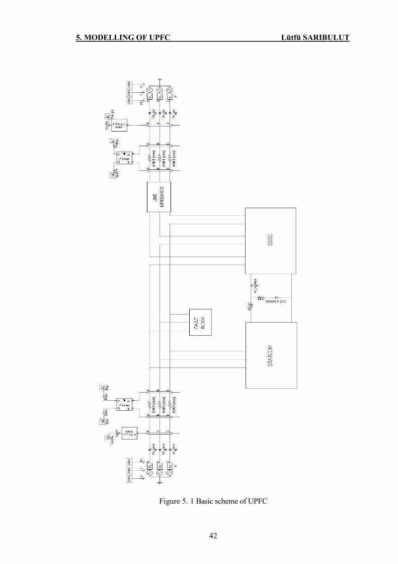
5. MODELLING OF UPFC Lütfü SARIBULUT
42
Figure 5. 1 Basic scheme of UPFC

5. MODELLING OF UPFC Lütfü SARIBULUT
43
5.1 Shunt Converter of UPFC
As mentioned before, UPFC which consists of a series and a shunt converter is
connected by a common dc link capacitor. The shunt converter has shown the same
function as STATCOM in UPFC. The structure of shunt converter is shown in the Figure
5.2. Two principles are fulfilled by the shunt converter listed below.
• To maintain the transmission line voltage at its reference value, reactive power is
absorbed or provided from the point of line where the shunt converter connected.
• To maintain DC voltage levels at its reference value by drawing the real power from
the line.
Figure 5. 2 Structure of shunt converter
The Insulated Gate Bipolar Transistors (IGBT) is used in the structure of the
converter. The harmonics are generated from converter naturally when firing pulses are
given to gates of IGBT. Some passive filters and coupled transformers are used to protect
the system from these harmonics, such as short circuit. The technical details of coupled
transformers are given in Appendix E.
Figure 5. 3 Passive filters used in shunt converter

5. MODELLING OF UPFC Lütfü SARIBULUT
44
The passive filters are used for three phases either to protect the system or to
eliminate the harmonics generated from converter naturally. These three phase filters are
shown in the Figure 5.3.
The reference sinusoidal signals generated from control mechanism of shunt
converter are compared with carrier signals shown in the Figure 5.7. The results of these
signals are firing angle of IGBT shown in the Figure 5.6.
5.1.1 Control Mechanism of Shunt Converter
The control mechanism of shunt converter is mentioned in chapter 4. It is
actualized in PSCAD/EMTDC program shown in the Figure 5.4 to 5.7. The real
power is drawn from the line to keep the capacitors voltage level at specified value. It is
accomplished by the way of changing the angle of the shunt converter output voltage.
When the angle of shunt converter is retarded from the line, the power is drawn from the
line to converter. When the angle is forwarded from the line, the real power is given from
the shunt converter to the line. Hence, DC voltage level is adjusted according to its
reference value.
When faults (ground, short circuit… etc.) are occurred at the bus (sending end)
connected the shunt converter, bus voltage level drops from its nominal value. The shunt
converter accomplishes from this situation by changing its output voltage magnitude. The
reactive power is drawn or given from the shunt converter to the line when bus voltage
magnitude is dropped or increased.
The reactive power is drawn from the line to compensate the bus voltage by shunt
converter when bus voltage magnitude is bigger than its reference value. Also reactive
power is given from shunt converter to line when bus voltage magnitude is dropped from
its reference value. The control mechanism of shunt converter is applied according to
references (Padiyar et al. 1998; Kannan et al. 2004), in this thesis shown in Figures 5.4
and 5.5.

5. MODELLING OF UPFC Lütfü SARIBULUT
45
Figure 5. 4 Control mechanism of DC voltage
Figure 5. 5 Control mechanism of bus voltage magnitude
The DC voltage level controller is given in the Figure 5.4. The DC voltage is
measured from the link between shunt and series converter. This value is divided to its
reference value and result is compared with desired DC set voltage value. The obtained
error value is given to PI controller to get angle theta for shunt converter output voltage.
The sending end bus voltage controller is shown in the Figure 5.5. The measured
bus voltage from sending end is compared with its reference value. The obtained error is
given to PI controller to get reference magnitude value for shunt converter output voltage.
The calculated angle and magnitude values are used to produce reference
sinusoidal signal for IGBT used in shunt converter presented in the Figure 5.6.
Figure 5. 6 Calculating reference signal for shunt converter

5. MODELLING OF UPFC Lütfü SARIBULUT
46
Figure 5. 7 Generating firing pulses for IGBT
The PLL is used to track the line voltage to find line angle ‘gamma’. The angles
gamma and theta are passed through the modulation function block and their modulation
is taken for 3600 in this block. The result is used in sinus block to generate three phase
balance reference voltage for SPWM shown in the Figure 5.7.
The obtained reference sinusoidal signals are used in the SPWM to compare with
triangular carrier signal to generate firing pulses for IGBT. These signals are named as
RetRon and RetRof. The generated from triangular block are named as TrgRon and
TrgRof, at 3500 KHz frequency. The reference signals and carrier signals are compared in
the Interpolated Firing Pulse block to produce firing angle for IGBT given in the Figure
5.7.
5.2 Series Converter of UPFC
The shunt and series converter are worked independently from each other. The
series converter has same properties with SSSC. It controls the series converter output
voltage to get the better utilized power flow in the line using DC voltage. As the DC
voltage is used by series converter, it is important to keep stable voltage level.
Considering this situation, shunt converter maintains DC voltage level at its reference
value mentioned above. The structure of series converter is given in the Figure 5.8.
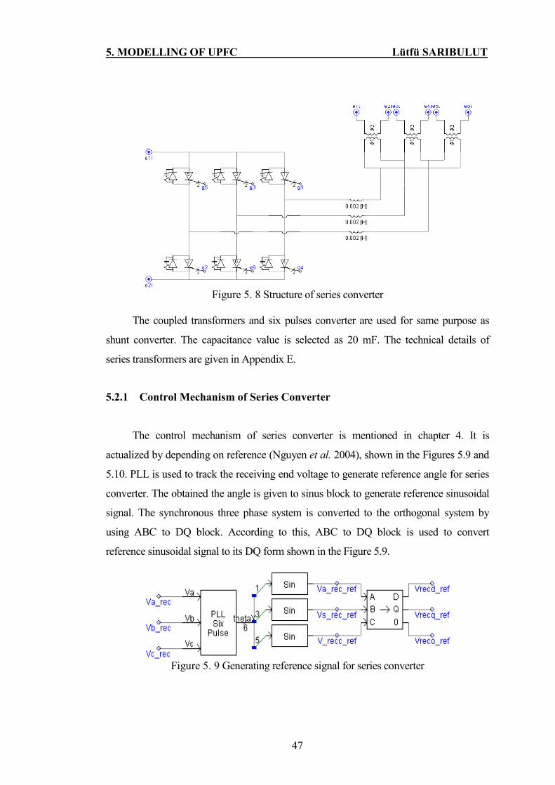
5. MODELLING OF UPFC Lütfü SARIBULUT
47
Figure 5. 8 Structure of series converter
The coupled transformers and six pulses converter are used for same purpose as
shunt converter. The capacitance value is selected as 20 mF. The technical details of
series transformers are given in Appendix E.
5.2.1 Control Mechanism of Series Converter
The control mechanism of series converter is mentioned in chapter 4. It is
actualized by depending on reference (Nguyen et al. 2004), shown in the Figures 5.9 and
5.10. PLL is used to track the receiving end voltage to generate reference angle for series
converter. The obtained the angle is given to sinus block to generate reference sinusoidal
signal. The synchronous three phase system is converted to the orthogonal system by
using ABC to DQ block. According to this, ABC to DQ block is used to convert
reference sinusoidal signal to its DQ form shown in the Figure 5.9.
Figure 5. 9 Generating reference signal for series converter

5. MODELLING OF UPFC Lütfü SARIBULUT
48
The measured signal from receiving end voltage is converted to its DQ form using
ABC to DQ block in PSCAD/EMTDC program shown in the Figure 5.10.
Figure 5. 10 Generating reference signal for series converter
The DQ form of receiving end voltage and its reference values are compared. The
error signals are multiplied with real and reactive power references. The obtained signals
are transformed to balance three phase signals by using DQ to ABC block shown in the
Figure 5.10. The result signals are used in SPWM in the same way as the shunt converter
to generate firing angle for IGBT.
5.3 Controller Design for UPFC in PSCAD /EMTDC Program
The performance analyzing of UPFC is investigated with different types of
controllers by using PSCAD/EMTDC program in this thesis. The controllers are
discussed in chapter 4. Only one kind P controller exists in main library of
PSCAD/EMTDC program. Other controllers are developed depending on their
mathematical equation and their truth is checked out in Matlab/Simulink. The developed
controllers in this thesis are listed below.

5. MODELLING OF UPFC Lütfü SARIBULUT
49
5.3.1 P Controller
The P controller is obtained by actualizing the equation ( )U Ke t= in the
literature. It contains only P gain. According to this equation, P controller is built by
considering the gain ( )Ke t in PSCAD/EMTDC program. The PSCAD/EMTDC
program software gives opportunity to create new component by using FORTRAN codes
and to build visual user interface. Also, P controller is created by using FORTRAN codes
and user interface shown in the Figure 5.11. The truth of P controller is controlled with
several gains in MATLAB/Simulink and reliability is provided.
Figure 5. 11 Proportional controller using in the control mechanism
5.3.2 PID Controller
The PID controller is obtained by considering the equation
1
1( ( ) ( ) )
O
tU K e t e t dt
T= + ∫ in the literature. It contains proportional, integral and
derivative gains. As PID controller does not exist in main library of PSCAD/EMTDC
program, it is created and built with its visual user interface shown in the Figure 5.12.
The truth of PID controller is tested with several gains in MATLAB/Simulink and
reliability is provided.

5. MODELLING OF UPFC Lütfü SARIBULUT
50
Figure 5. 12 PID controller using in the control mechanism
5.3.3 FUZZY Controller
The details of fuzzy controller are discussed in chapter 4. The fuzzy controller is
created by using FORTRAN codes and visual user interface. The created fuzzy controller
is shown in the Figure 5.13 and its codes are given at Appendix D.
Figure 5. 13 Fuzzy controller using in the control mechanism
5.4 Conclusion
The shunt converter and series converter are modeled in PSCAD/EMTDC program.
The details of its structure and control mechanism of UPFC are studied in this chapter.
The developed controllers for UPFC are discussed.
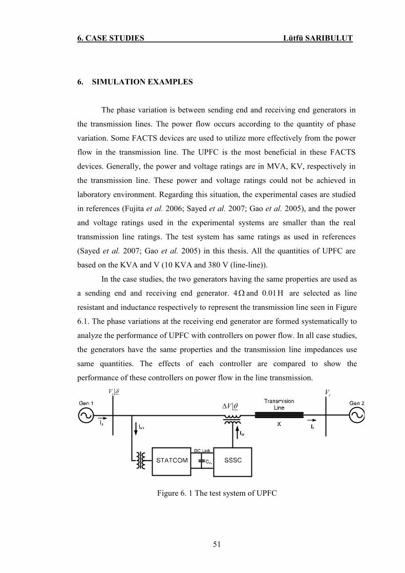
6. CASE STUDIES Lütfü SARIBULUT
51
6. SIMULATION EXAMPLES
The phase variation is between sending end and receiving end generators in
the transmission lines. The power flow occurs according to the quantity of phase
variation. Some FACTS devices are used to utilize more effectively from the power
flow in the transmission line. The UPFC is the most beneficial in these FACTS
devices. Generally, the power and voltage ratings are in MVA, KV, respectively in
the transmission line. These power and voltage ratings could not be achieved in
laboratory environment. Regarding this situation, the experimental cases are studied
in references (Fujita et al. 2006; Sayed et al. 2007; Gao et al. 2005), and the power
and voltage ratings used in the experimental systems are smaller than the real
transmission line ratings. The test system has same ratings as used in references
(Sayed et al. 2007; Gao et al. 2005) in this thesis. All the quantities of UPFC are
based on the KVA and V (10 KVA and 380 V (line-line)).
In the case studies, the two generators having the same properties are used as
a sending end and receiving end generator. 4Ω and 0.01Η are selected as line
resistant and inductance respectively to represent the transmission line seen in Figure
6.1. The phase variations at the receiving end generator are formed systematically to
analyze the performance of UPFC with controllers on power flow. In all case studies,
the generators have the same properties and the transmission line impedances use
same quantities. The effects of each controller are compared to show the
performance of these controllers on power flow in the line transmission.
sV δrV
V θ∆
Figure 6. 1 The test system of UPFC

6. CASE STUDIES Lütfü SARIBULUT
52
The simulation and experimental studies are based on the effectiveness of
UPFC on power flow in the literature. However, the effectiveness of UPFC is not
observed on faults so much. The case of phase-to-ground fault is studied in reference
(Schauder et al.1998) and the series part of UPFC becomes electronic bypass
immediately to protect the series converter. The behaviors of UPFC are seen on the
phase to ground faults, when the phase to ground fault occurs in reference (Schauder
et al.1998). The same faults cases are studied and the performance of controllers is
compared when the 3-phase-to-ground fault is applied in the case studies 3 and 4.
6.1 Case 1
The receiving end generator is retarded from sending end generator, and the
power flow of the line with UPFC and without UPFC is observed in this case. The
technical details of generators are given Appendix E. The power flow is provided by
retarding 30.00 the receiving end generator from the sending end generator. The
amounts of real and reactive power are 2.1 KW and 0.7 KVAR, respectively when
the system is worked without UPFC. In the same way, the real and reactive powers
are 2.45 KW and 0.1 KVAR, respectively, when UPFC is activated in the line. The
PI controller is used in the control mechanism of UPFC when the results are taken.
These results are compared graphically in Figure 6.2 and 6.3. The reference value of
P is selected as 10 and the reference value Q is selected as 1 for case studies 1 and 2.
Real Power
0.00 0.50 1.00 1.50 2.00 2.50 3.00 ...
... ...
-0.0020
-0.0010
0.0000
0.0010
0.0020
0.0030
0.0040
y (MVA)
Pre with UPFC Pre without UPFC
Figure 6. 2 Real power quantities of the line with and without UPFC
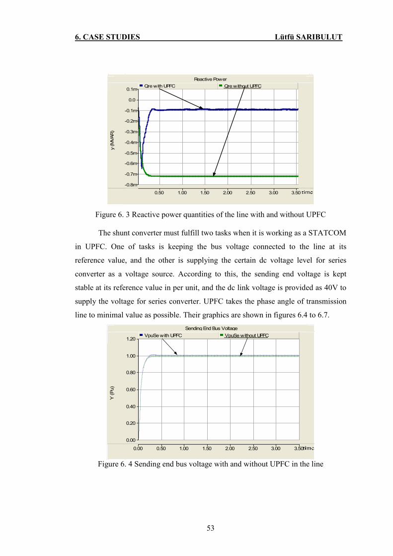
6. CASE STUDIES Lütfü SARIBULUT
53
...
Reactive Power
0.50 1.00 1.50 2.00 2.50 3.00 3.50 ...
... ...
-0.8m
-0.7m
-0.6m
-0.5m
-0.4m
-0.3m
-0.2m
-0.1m
0.0
0.1m
y (MVAR)
Qre with UPFC Qre without UPFC
Figure 6. 3 Reactive power quantities of the line with and without UPFC
The shunt converter must fulfill two tasks when it is working as a STATCOM
in UPFC. One of tasks is keeping the bus voltage connected to the line at its
reference value, and the other is supplying the certain dc voltage level for series
converter as a voltage source. According to this, the sending end voltage is kept
stable at its reference value in per unit, and the dc link voltage is provided as 40V to
supply the voltage for series converter. UPFC takes the phase angle of transmission
line to minimal value as possible. Their graphics are shown in figures 6.4 to 6.7.
Sending End Bus Voltage
0.00 0.50 1.00 1.50 2.00 2.50 3.00 3.50 ...
... ...
0.00
0.20
0.40
0.60
0.80
1.00
1.20
Y (Pu)
VpuSe with UPFC VpuSe without UPFC
Figure 6. 4 Sending end bus voltage with and without UPFC in the line

6. CASE STUDIES Lütfü SARIBULUT
54
Receiving End Bus Volatge
0.00 0.50 1.00 1.50 2.00 2.50 3.00 3.50 ...
...
-2.0
-1.0
0.0
1.0
2.0
3.0
y (pu)
Vre_pu with UPFC VpuRe without UPFC
Figure 6. 5 Receiving end bus voltage with and without UPFC in the line
DC Voltage
0.00 0.50 1.00 1.50 2.00 2.50 3.00 ...
...
0.0000
0.0050
0.0100
0.0150
0.0200
0.0250
0.0300
0.0350
0.0400
0.0450
y (KV)
dc_voltage
Figure 6. 6 Dc link voltage
Phase Difference
0.00 0.50 1.00 1.50 2.00 2.50 3.00 ...
...
-10.0
-8.0
-6.0
-4.0
-2.0
0.0
2.0
y (pu)
Phase difference with UPFC Phase difference without UPFC
Figure 6. 7 Phase difference between busses with and without UPFC

6. CASE STUDIES Lütfü SARIBULUT
55
6.2 Case 2
The direction of power flow is considered as from sending to receiving end
side in the line and mathematical equations are calculated in terms of this power flow
direction. In other words, from the equation 4.3 and 4.7, when the phase of receiving
end generator is retarded from the sending end generator, the power flow is provided
from sending end side to receiving end side. According to the performance of the
controllers, the phase of receiving end generator is changed systematically and the
results are compared as a power flow of the line. The results of power flow for phase
variation are listed in table 6.2.
Table 6. 1 The power flow of the line for phase variations
Phase angle of Receiving end Generator ( 0 )
180 210 240 270 300 320 330 345 355
P(KW) -1.39 0.90 2.78 3.72 3.44 2.67 2.11 1.11 0.38 Without UPFC
Q(KVAR) -1.5 -2.10 -2.26 -2.02 -1.4 -0.97 -0.72 -0.34 -0.11
P(KW) -1.50 1.70 4.03 4.70 4.00 2.95 2.29 1.21 0.45 P Controller
With UPFC Q(KVAR) -2.29 -2.82 -1.96 -1.17 -0.62 -0.42 -0.37 -0.036 -0.39
P(KW) -1.52 1.67 3.97 4.6 4.14 3.09 2.43 1.37 0.61 PI Controller
With UPFC Q(KVAR) -2.26 -2.84 -1.99 -1.19 -0.42 -0.15 -0.09 0.04 0.16
P(KW) -1.54 2.03 4.37 4.94 4.15 3.06 2.4 1.35 0.61 PID Controller
With UPFC Q(KVAR) -2.22 -2.78 -1.70 -0.91 -0.39 -0.21 0.14 0.01 0.16
P(KW) -1.52 1.66 4.50 5.30 4.33 3.14 3.14 1.41 0.68 FUZZY Controller
With UPFC Q(KVAR) -2.25 -2.85 -1.50 0.40 -0.07 -0.08 -0.088 0.07 0.22

6. CASE STUDIES Lütfü SARIBULUT
56
6.3 Case 3
As mentioned before in reference (Schauder et al.1998), the phase-to-ground
fault occurs, and excessive current flows on phase A. In the same way, the three
phase fault is applied at the sending end seen in figure 6.8. When UPFC senses fault,
it immediately activates the electronic bypass to protect the series converter in case
studies 3 and 4. The test system is shown in the following.
sV δrV
V θ∆
Figure 6. 8 Test system of case study 3
The fault is started at 1.4 sec and its duration is 0.2 sec in this case. The
excessive current flows on the short circuit impedance 53.03+j0.1688Ω . In the
control mechanism, the reference value of P and Q are selected as 1 for case studies
3 and 4. The shunt converter remains operational to supply reactive compensation to
the line and the series converter is closed by breaker during the fault time. The bus
voltage and the reactive power are provided to keep theirs reference and nominal
values when UPFC is connected to the system. The results of reactive power
quantities and receiving end bus voltage are compared graphically by using in figure
6.9 to 6.12.
Considering the results, the P controller has not effect on reactive power
compensation and bus voltage control when the fault occurs. The PI, PID and fuzzy
controllers are more effective than P controller when the fault appears in the line.
The fuzzy controller is the most effective on power flow in these controllers.

6. CASE STUDIES Lütfü SARIBULUT
57
Reactive Power
0.20 0.40 0.60 0.80 1.00 1.20 1.40 1.60 1.80 ...
... ...
-0.0025
-0.0020
-0.0015
-0.0010
-0.0005
0.0000
0.0005
0.0010
MVAR
Qre with UPFC Qre without UPFC
Receiving End Voltage
0.00 0.25 0.50 0.75 1.00 1.25 1.50 1.75 2.00 2.25 ...
... ...
-0.50
-0.25
0.00
0.25
0.50
0.75
1.00
1.25
1.50
1.75
y (pu)
VpuRe wit UPFC VpuRe without UPFC
Figure 6. 9 The P controller results when the fault was occurred
Reactive Power
0.50 1.00 1.50 2.00 2.50 3.00 3.50 ...
... ...
-0.0025
-0.0020
-0.0015
-0.0010
-0.0005
0.0000
0.0005
0.0010
0.0015
MVAR
Qre with UPFC Qre without UPFC
Receiving End Voltage
0.00 0.50 1.00 1.50 2.00 2.50 3.00 ...
... ...
-0.50
-0.25
0.00
0.25
0.50
0.75
1.00
1.25
1.50
Y (pu)
VpuRe with UPFC VpuRe without UPFC
Figure 6. 10 The PI controller results when the fault was occurred
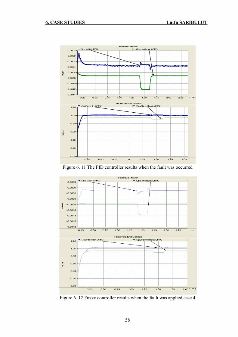
6. CASE STUDIES Lütfü SARIBULUT
58
Reactive Power
0.25 0.50 0.75 1.00 1.25 1.50 1.75 2.00 2.25 ...
... ...
-0.0014
-0.0012
-0.0010
-0.0008
-0.0006
-0.0004
-0.0002
0.0000
0.0002
MVAR
Qre with UPFC Qre without UPFC
Receiving End Voltage
0.25 0.50 0.75 1.00 1.25 1.50 1.75 2.00 ...
... ...
0.00
0.20
0.40
0.60
0.80
1.00
1.20
Y (pu)
VpuRe with UPFC VpuRe without UPFC
Figure 6. 11 The PID controller results when the fault was occurred
Receiving End Voltage
0.25 0.50 0.75 1.00 1.25 1.50 1.75 2.00 ...
... ...
0.00
0.20
0.40
0.60
0.80
1.00
1.20
Y (pu)
VpuRe with UPFC VpuRe without UPFC
Reactive Power
0.25 0.50 0.75 1.00 1.25 1.50 1.75 2.00 2.25 ...
... ...
-0.0018
-0.0015
-0.0013
-0.0010
-0.0008
-0.0005
-0.0003
0.0000
0.0003
MVAR
Qre with UPFC Qre without UPFC
Figure 6. 12 Fuzzy controller results when the fault was applied case 4

6. CASE STUDIES Lütfü SARIBULUT
59
6.4 Case 4
Two transmission lines having the same properties are used and fed by two
generators in this case. The 3-phase-to-ground fault is applied in the same way as in
case 3. The fault is started at 3.5 sec and its duration is 0.2. The UPFC is connected
to the line 2 shown in figure 6.13.
sV δrV
V θ∆
Figure 6. 13 The test system of case study 4
When the results are compared according to reactive power compensation and
bus voltage control, the P and PI controllers are insufficient in the compensation and
control of quantities. However, the PID and fuzzy controllers make more effective
compensation of reactive power and controlling of bus voltage. The results of
controllers are shown graphically in figure 6.14 to 6.17.

6. CASE STUDIES Lütfü SARIBULUT
60
Reactive Power
0.50 1.00 1.50 2.00 2.50 3.00 3.50 4.00 ...
... ...
-0.0020
-0.0015
-0.0010
-0.0005
0.0000
0.0005
MVAR
Qre with UPFC Qre without UPFC
Receiving End Voltage
0.50 1.00 1.50 2.00 2.50 3.00 3.50 4.00 ...
... ...
0.00
0.20
0.40
0.60
0.80
1.00
1.20
1.40
Y (pu)
VpuRe with UPFC VpuRe without UPFC
Figure 6. 14 The P controller results when the fault was occurred
Reactive Power
0.50 1.00 1.50 2.00 2.50 3.00 3.50 4.00 4.50 ...
... ...
-0.0014
-0.0012
-0.0010
-0.0008
-0.0006
-0.0004
-0.0002
0.0000
0.0002
MVAR
Qre with UPFC Qre without UPFC
Receiving End Voltage
0.50 1.00 1.50 2.00 2.50 3.00 3.50 4.00 4.50 ...
... ...
0.00
0.20
0.40
0.60
0.80
1.00
1.20
Y (pu)
VpuRe with UPFC VpuRe without UPFC
Figure 6. 15 The PI controller results when the fault was occurred

6. CASE STUDIES Lütfü SARIBULUT
61
Receiving End Voltage
0.50 1.00 1.50 2.00 2.50 3.00 3.50 4.00 4.50 ...
... ...
0.00
0.20
0.40
0.60
0.80
1.00
1.20
Y (pu)
VpuRe with UPFC VpuRe without UPFC
Reactive Power
0.50 1.00 1.50 2.00 2.50 3.00 3.50 4.00 ...
... ...
-0.0016
-0.0014
-0.0012
-0.0010
-0.0008
-0.0006
-0.0004
-0.0002
0.0000
0.0002
MVAR
Qre with UPFC Qre without UPFC
Figure 6. 16 The PID controller results when the fault was occurred
Reactive Power
0.50 1.00 1.50 2.00 2.50 3.00 3.50 4.00 4.50 ...
... ...
-0.0018
-0.0015
-0.0013
-0.0010
-0.0008
-0.0005
-0.0003
0.0000
0.0003
MVAR
Qre with UPFC Qre without UPFC
Receiving End Voltage
0.50 1.00 1.50 2.00 2.50 3.00 3.50 4.00 ...
... ...
0.00
0.20
0.40
0.60
0.80
1.00
1.20
Y (pu)
VpuRe with UPFC VpuRe without UPFC
Figure 6. 17 The Fuzzy controller results when the fault was occurred

6. CASE STUDIES Lütfü SARIBULUT
62
6.5 Conclusion
The performance of controllers is tested and the results are. The case studies 1
and 2 show the performance of controllers on power flow while case studies 3 and 4
show the performance of controllers when the phase-to-ground fault occurs. The P
controller’s results show the effective performance neither at the bus voltage control
nor at the reactive power compensation. However, other controllers have more
effective performance than P controller. The fuzzy controller shows the best
performance among these controllers.

7. CONCLUSIONS Lütfü SARIBULUT
63
7. CONCLUSIONS
This thesis deals with FACTS devices known as the Unified Power Flow
Controller that is used to maintain and improve power system operation and stability.
The research carried out in this thesis has focus on investigation of performance of
UPFC on power flow with different controllers.
The derivation of mathematical framework of UPFC and the understanding of
this basic operating principle were discussed. This framework confirmed the superior
capabilities of UPFC in the power flow applications over traditional reactive power
compensators.
The Power System Simulation CAD (PSCAD/EMTDC program) is used for the
simulation of UPFC. This program includes device models in its library. It includes
only PI controllers for the modeling of UPFC. In this thesis, the P, PID and fuzzy
controllers were developed and added as a new component into PSCAD/EMTDC
program library. Additionally, conventional as well as intelligent control schemes can
be applied in PSCAD/EMTDC program easily. The disadvantage of the simulation
packages is the simulation time. The simulation time is a function of the number of the
time steps. Adding new devices and the increase in the system size enhance the
simulation time leading to the quite time consuming simulations.
The comprehensive simulation cases are examined, and the results show that the
proposed model and controllers are both effective and reliable. The detailed
observation has been made on power system parameters, such as real and reactive
power flows as well as bus voltage control in this study. Moreover, several case studies
have been made in order to investigate the effects of controllers on the power flow in
the power system. All the results have been fully represented by different types of
graphs in order to give clear idea about the main concern. Furthermore, the main
conclusions of this study can be summarized as:
The capability of UPFC on controlling the power flow is demonstrated in the
case studies 1 and 2. The receiving end generator is retarded 30.00 from the sending
end generator in the case 1. The real and reactive powers are 2.1 KW and 0.7 KVAR
respectively when UPFC is not activated while the real and reactive power are 2.45

7. CONCLUSIONS Lütfü SARIBULUT
64
KW and 0.1 KVAR respectively when UPFC is activated in the line. According to
these results, the active power is increased 28.5 %, and reactive power is decreased
85.7 % by UPFC in terms of not activated UPFC in the line. The receiving end
generator is retarded by applying different phase values, and the results are listed to
see the performance of the controllers on the value table. From the simulation results,
the fuzzy controller shows the best performance among the other controllers.
The fault occurs in the transmission line because of the several reasons such
as phase-to-ground faults. The FACTS devices are used to prevent the damage when
the faults occur in the system. To see the performances of UPFC on the faults
conditions, the three-phase fault is applied to the transmission line, and results are
compared in terms of compensation of the reactive power and controlling the bus
voltage in case studies 3 and 4.
The results show that the P controller could not compensate the reactive power
and control the bus voltage. However, other controllers show good performance on
these quantities. The PI and PID controllers obtain the same values while the fuzzy
controller shows the best performance among these controllers.

APPENDIX A Lütfü SARIBULUT
65
APPENDIX A
Voltage Source Converter
The form of VSC-based designs is used to advance solutions for STATCOM,
UPFC, and SSSC etc, including its structure to name a few.
The basic duty of VSC used in the FACTS is to generate a three-phase voltage
utilized from the dc link capacitor such that in the series part of UPFC, it is able to
operate as an AC voltage source which injects three phase voltages in series with the
power system for compensation purposes. As a conventional configuration of the
VSC, the six-pulse converter is used. It includes six power semiconductor switching
devices (GTO, GCT, IGBT, etc) with anti-parallel-connected diode joined with heat
sinks and auxiliary equipment for gating, monitoring and grading. The VSC is
connected to the transmission system via a series coupling transformer and in parallel
with a dc capacitor link. By means of proper control, the amplitude and phase of the
injected voltage can be varied and combined with desired requirements depending on
used FACTS devices. Mainly, the operation of VSC is able to provide 2 types of
connections.
• Shunt Connected VSC: The VSC is connected to the power system via a shunt
connected transformer, as in the STATCOM configuration of Figure A1. The active
power and the reactive power are exchanged between the converter by changing the
amplitude and the phase angle of the produced output voltage, and the AC system
can be controlled in a similar manner to that of a rotating synchronous machine. The
reactive power exchange bi-directionally between the VSC and the power system,
and it can be adjusted by varying the amplitude of the output voltage. If the
amplitude of the output voltage is increased according to the AC system voltage, the
VSC generates reactive power to give the power system. If the amplitude of the
output voltage is decreased according to the AC system voltage, the VSC absorbs
reactive power from the power system. The real power is exchanged bi-directionally
between the VSC and the power system. It can be realized by changing the phase
angle between the output voltage and the AC system voltage. If the phase angle of

APPENDIX A Lütfü SARIBULUT
66
output voltage is advanced from the AC system voltage, the VSC supplies real power
to the AC power system. If the output voltage is lagged from AC system voltage, the
VSC absorbs real power from the AC power system. The real power exchange is
required by another VSC, battery, and dc energy storage device like a super-
conducting magnet. The exchange of real and reactive power is implemented
individually. The power ratings of the VSC are calculated by the product of the
power system voltage and the maximum output current.
• Series Connected VSC: In this case, the VSC is connected to the power system via
a series connected transformer, as in the SSSC configuration of Figure A1. The
magnitude and the angle of the injected voltage can be controlled by changing the
amplitude and the phase angle of the produced output voltages. The VSC acts as an
AC voltage source, and its output voltage injects in series with the line. The current
flowing through the VSC corresponds to the line current. The power ratings of the
VSC are calculated by the product of the maximum injected voltage and the
maximum line current. The VSC provides only reactive power to the power system,
when the injected voltage is controlled via a quadrature relationship with the line
current. In this situation, there is no need for energy storage device on the dc
terminal. If the injected voltage is controlled in a four-quadrant manner (360 deg.) to
the line current, the VSC provides both real power and reactive power to the AC
power system. In this situation, another energy storage device is needed for the real
power exchanged on the dc terminal.
Figure A1 Basic structure of shunt and series VSCs.

APPENDIX B Lütfü SARIBULUT
67
APPENDIX B
Rotating (DQ) Transformation
The transformation of the three-phase stationary coordinate system into the DQ
rotating coordinate system is called the DQ transformation. This transformation is
made in two steps:
• The three-phase stationary coordinate system is transformed into the two-phase,
so-called αβ stationary coordinate system.
• The αβ stationary coordinate system is transformed into rotating coordinate
system, so-called dq transformation.
These steps are shown in figure B.1, B.2, B.3.
The vector representation in any n-dimensional space is completed through the
product of a transpose n-dimensional vector (base) of coordinate units and a vector
representation of the vector, whose elements are corresponding projections on each
coordinate axis, is normalized by their unit values. The three-phase (three
dimensional) space is given as vectorial in equation 1:
[ ]xa
X a b c xu u uabc b
xc
=
(B.1)
The three-phase vector representation transforms to dq vector representation
(zero-axis component is 0) through the transformation matrix T by assuming a balanced three-phase system ( 0ox = ), defined as:
2 2cos( ) cos( ) cos( )
3 32 2 2
sin( ) sin( ) sin( )3 3 3
wt wt wt
T wt wt wt
π π
π π
− +
= − − − − +
(B.2)
In other words, the transformation from xa
X xabc b
xc
=
(three-phase coordinates) to
xdXdq
xq
=
(DQ rotating coordinates), called Park’s transformation, is obtained
through the multiplication the αβ stationary coordinate system

APPENDIX B Lütfü SARIBULUT
68
[ ] [ ]
11 0
2
2 1 3 10
3 2 2 2
1 3 1
2 2 2
a a b cu u u u u uβ = −
− −
Figure B1 the transformation from abc to Figure B2 the transformation from αβ to the αβ stationary coordinate system the dq stationary coordinate
Figure B.3 Park’s transformation from three-phase to rotating dq0 coordinate
system of the vector abcX by the matrix T:
dq abcX TX= (B.3)
The inverse transformation matrix (from DQ to ABC) is defined as:
cos( ) sin( )
2 2' cos( ) sin( )
3 32 2
cos( ) sin( )3 3
wt wt
T wt wt
wt wt
π π
π π
−
= − − −
+ − +
(B.5)
The inverse transformation is calculated as: 'abc dqX T X= (B.4)
[ ] [ ]
1cos sin
22 2 2 1
0 cos( ) sin( )3 3 3 2
2 2 1cos( ) sin( )
3 3 2
d q a b cu u u u u u
θ θ
π πθ θ
π πθ θ
−
= − − −
+ − +
[ ] [ ]cos sin 0
0 0 sin cos 0
0 0 1
d qu u u u u u
θ θα β θ θ
−
=

APPENDIX C Lütfü SARIBULUT
69
APPENDIX C
Pulse Width Modulation
One type of internal converter control scheme is Pulse Width Modulation
(PWM). The converter can be applied as types of two-level or multilevel converters.
The AC output voltage can be controlled by varying the width of the voltage pulses
in these converters. There is only one turn-on and one turn-off devices in per cycle.
Another approach is to have multiple-pulses per half cycle, and then vary the width
of the pulses to change the amplitude of the AC voltage. The principle reason for
incorporating the PWM scheme is such that the AC output voltage can easily change,
and the order harmonics is reduced in lower level. The switching losses are increased
with the rise of the pulse number and cannot be neglected when the PWM scheme
uses.
Controlling the converter gain, and consequently the converter output
voltage, is thought as the main advantage of PWM converters. There are many PWM
techniques used and applied with different converter configurations. The Sinusoidal
Pulse Width Modulation (SPWM) is the most popular method in PWM technique. In
the SPWM, the width of each pulse is varied proportionally to the amplitude of a
sinus wave, as seen in figure C.2.
C.1 Working Principle
The carrier frequency, the main frequency and the modulation index, which is
an output from the main control schemes of UPFC, are used as inputs to the shunt
and series pulse generator. The position of IGBTs is considered according to their
connections. The diodes 1 and 4, and IGBTs 1 and 4 must be anti-parallel on one
phase-leg of three-phase bridge converter. It is seen in figure C.1.
The comparison of the two types of control signals are shown in Figure C.2,
one of them is main-frequency sinus wave representing one phase, and the other is

APPENDIX C Lütfü SARIBULUT
70
3.5 KHz frequency saw- tooth wave signal. According to these signals, the firing
pulses of IGBTs are produced as follows.
Figure C.l Simple Voltage Sourced Converter
In the crossing points of the saw-tooth wave and the corresponding phase of
sinus wave, the turn-on and turn-off pulses are obtained and given to the devices.
When the negative slope of the saw-tooth wave crosses the phase A of sinus wave,
the turn-on pulse for device 1 and turn- off pulse for device 4 are obtained. When the
positive slope of the saw-tooth wave crosses the phase A of sinus wave, the turn-off
pulse for device 1 and turn-on pulse for device 4 are obtained. The pulses are wider
in the middle of each half sinus wave when comparing the ends of the half sinus
wave.
Ae
/ 2Vd
/ 2Vd−
5
10
5−
10−
Ia
Figure C.2 Principle of Pulse with Modulation

APPENDIX C Lütfü SARIBULUT
71
The switches are controlled by turn-on and turn-off pulses, which correspond
to the crossing points of the control waveform with the carrier waveform of
corresponding phase in the six pulse voltage-sourced converter. The fundamental
frequency of the output voltage (50 HZ or 60 HZ) is determined by the frequency of
the carrier signal. The frequency modulation ratio f
m is the ratio between
frequencies of the carrier and control waveforms, as given follow.
fcarrier
mf
fcontrol
= (C.1)
The magnitude of the carrier waveform is controlled from zero to its maximum
value by varying the amplitude of the control waveform and the result that the pulse
width can vary from 0 to 180 0 . The modulation ratio am defines the ratio between
the control and carrier waveforms:
dcontrol
ma
dcarrier
= (C.2)
The dc midpoint voltage for the phase A is shown figure C.2 as waveformAe ,
which fluctuates between –Vdc/2 and +Vdc/2. The amplitude of the phase at
fundamental frequency component to the dc midpoint voltage is am times Vdc/2:
2
Vdc
e ma a
= (C.3)
The equations for the magnitude of the shunt and series-injected voltages are as
follow, when the PWM technique is applied to the two converters:
( ) / 2 2Vsh m V n Vsh dc sh B
= (C.4)
( ) / 2 2Vsh m V n Vse dc se B
= (C.5)
The amplitude modulation index of the shunt converter control signal is shm ,
the amplitude modulation index of the series converter control signal issem , the
shunt transformer turn ratio isshn , the series transformer turn ratio is
sen , the system
side base voltage isBV .
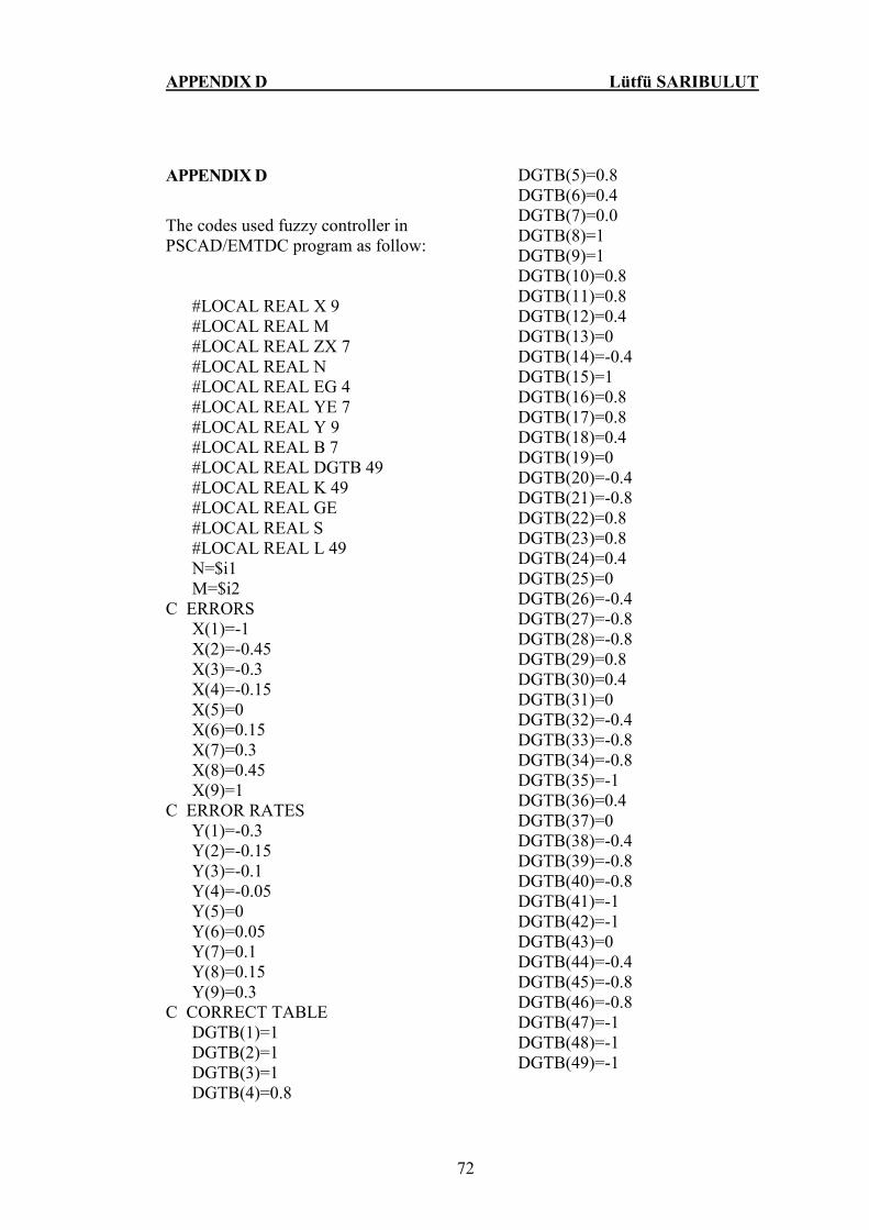
APPENDIX D Lütfü SARIBULUT
72
APPENDIX D
The codes used fuzzy controller in PSCAD/EMTDC program as follow: #LOCAL REAL X 9 #LOCAL REAL M #LOCAL REAL ZX 7 #LOCAL REAL N #LOCAL REAL EG 4 #LOCAL REAL YE 7 #LOCAL REAL Y 9 #LOCAL REAL B 7 #LOCAL REAL DGTB 49 #LOCAL REAL K 49 #LOCAL REAL GE #LOCAL REAL S #LOCAL REAL L 49 N=$i1 M=$i2 C ERRORS X(1)=-1 X(2)=-0.45 X(3)=-0.3 X(4)=-0.15 X(5)=0 X(6)=0.15 X(7)=0.3 X(8)=0.45 X(9)=1 C ERROR RATES Y(1)=-0.3 Y(2)=-0.15 Y(3)=-0.1 Y(4)=-0.05 Y(5)=0 Y(6)=0.05 Y(7)=0.1 Y(8)=0.15 Y(9)=0.3 C CORRECT TABLE DGTB(1)=1 DGTB(2)=1 DGTB(3)=1 DGTB(4)=0.8
DGTB(5)=0.8 DGTB(6)=0.4 DGTB(7)=0.0 DGTB(8)=1 DGTB(9)=1 DGTB(10)=0.8 DGTB(11)=0.8 DGTB(12)=0.4 DGTB(13)=0 DGTB(14)=-0.4 DGTB(15)=1 DGTB(16)=0.8 DGTB(17)=0.8 DGTB(18)=0.4 DGTB(19)=0 DGTB(20)=-0.4 DGTB(21)=-0.8 DGTB(22)=0.8 DGTB(23)=0.8 DGTB(24)=0.4 DGTB(25)=0 DGTB(26)=-0.4 DGTB(27)=-0.8 DGTB(28)=-0.8 DGTB(29)=0.8 DGTB(30)=0.4 DGTB(31)=0 DGTB(32)=-0.4 DGTB(33)=-0.8 DGTB(34)=-0.8 DGTB(35)=-1 DGTB(36)=0.4 DGTB(37)=0 DGTB(38)=-0.4 DGTB(39)=-0.8 DGTB(40)=-0.8 DGTB(41)=-1 DGTB(42)=-1 DGTB(43)=0 DGTB(44)=-0.4 DGTB(45)=-0.8 DGTB(46)=-0.8 DGTB(47)=-1 DGTB(48)=-1 DGTB(49)=-1
APPENDIX D Lütfü SARIBULUT
73
C DETERMINATION OF TRAJECTORY EG(1)=(1/X(6) EG(2)=-EG(1)
EG(3)=(1/Y(6)) EG(4)=-EG(3) C OUTPUT CALCULATION ACCORDING TO ERROR IF(N.GE.X(1).AND.N.LT.X(2)) ZX(7)=1 IF(N.GE.X(2).AND.N.LT.X(3)) ZX(7)=EG(2)*(N-X(3)) IF(N.GE.X(2).AND.N.LT.X(3)) ZX(6)=EG(1)*(N-X(2)) IF(N.GE.X(3).AND.N.LT.X(4)) ZX(6)=EG(2)*(N-X(4)) IF(N.GE.X(3).AND.N.LT.X(4)) ZX (5)=EG(1)*(N-X(3)) IF(N.GE.X(4).AND.N.LT.X(5)) ZX(5)=EG(2)*(N-X(5)) IF(N.GE.X(4).AND.N.LT.X(5)) ZX(4)=EG(1)*(N-X(4)) IF(N.GE.X(5).AND.N.LT.X(6)) ZX(4)=EG(2)*(N-X(6)) IF(N.GE.X(5).AND.N.LT.X(6)) ZX(3)=EG(1)*(N-X(5)) IF(N.GE.X(6).AND.N.LT.X(7)) ZX(3)=EG(2)*(N-X(7)) IF(N.GE.X(6).AND.N.LT.X(7)) ZX(2)=EG(1)*(N-X(6)) IF(N.GE.X(7).AND.N.LT.X(8)) ZX(2)=EG(2)*(N-X(8)) IF(N.GE.X(7).AND.N.LT.X(8)) ZX(1)=EG(1)*(N-X(7)) IF(N.GE.X(8).AND.N.LT.X(9)) ZX(1)=1 C OUTPUT CALCULATION ACCORDING TO ERROR RATES IF(M.GE.Y(1).AND.M.LT.Y(2)) B(7)=1 IF(M.GE.Y(2).AND.M.LT.Y(3)) B(7)=EG(4)*(M-Y(3)) IF(M.GE.Y(2).AND.M.LT.Y(3)) B(6)=EG(3)*(M-Y(2)) IF(M.GE.Y(3).AND.M.LT.Y(4)) B(6)=EG(4)*(M-Y(4)) IF(M.GE.Y(3).AND.M.LT.Y(4)) B(5)=EG(3)*(M-Y(3)) IF(M.GE.Y(4).AND.M.LT.Y(5)) B(5)=EG(4)*(M-Y(5)) IF(M.GE.Y(4).AND.M.LT.Y(5)) B(4)=EG(3)*(M-Y(4)) IF(M.GE.Y(5).AND.M.LT.Y(6)) B(4)=EG(4)*(M-Y(6)) IF(M.GE.Y(5).AND.M.LT.Y(6)) B(3)=EG(3)*(M-Y(5)) IF(M.GE.Y(6).AND.M.LT.Y(7)) B(3)=EG(4)*(M-Y(7)) IF(M.GE.Y(6).AND.M.LT.Y(7)) B(2)=EG(3)*(M-Y(6))

APPENDIX D Lütfü SARIBULUT
74
IF(M.GE.Y(7).AND.M.LT.Y(8)) B(2)=EG(4)*(M-Y(8)) IF(M.GE.Y(7).AND.M.LT.Y(8)) B(1)=EG(3)*(M-Y(7)) IF(M.GE.Y(8).AND.M.LT.Y(9)) B(1)=1 C MINIMIZATION OF TWO INPUTS DO I=1,7,1 K(I)= MIN (ZX(1),B(I)) END DO DO I=1,7,1 K(I+7)= MIN (ZX(2),B(I)) END DO DO I=1,7,1 K(I+14)= MIN (ZX(3),B(I)) END DO DO I=1,7,1 K(I+21)= MIN (ZX(4),B(I)) END DO DO I=1,7,1 K(I+28)= MIN (ZX(5),B(I)) END DO DO I=1,7,1 K(I+35)= MIN (ZX(6),B(I)) END DO DO I=1,7,1 K(I+42)= MIN (ZX(7),B(I)) END DO S=0 GE=0 DO I=1,49,1 L(I)= DGTB(I)*K(I) END DO DO I=1,49,1 S=S+L(I) GE=GE+ K(I) END DO $o13=S/GE

APPENDIX E Lütfü SARIBULUT
75
APPENDIX E
The technical details of sending end and receiving end generators:
Sending End Generator Based MVA (3-phase) : 0.01 [MVA]
Base Voltage (L-L, RMS) : 0.380 [kV] Base Frequency : 50.0 [Hz] Phase : 0.0 [°]
Receiving End Generator
Based MVA (3-phase) : 0.01 [MVA] Base Voltage (L-L, RMS) : 0.380 [kV] Base Frequency : 50.0 [Hz] Phase : 0.0 [°]
The technical details of shunt converter transformers:
Based MVA (3-phase) :0.003 [MVA] Winding #1 Voltage (L-L, RMS) :0.380 [kV] Winding #2 Voltage (L-L, RMS) :0.040 [kV] Base Operation Frequency :50.0 [Hz]
The technical details of series converter transformers:
Based MVA (3-phase) :0.003 [MVA] Winding #1 Voltage (L-L, RMS) :0.110 [kV] Winding #2 Voltage (L-L, RMS) :0.110 [kV] Base Operation Frequency :50.0 [Hz]
The technical details of generators used in case studies:
Sending End Generator Based MVA (3-phase) : 0.01 [MVA]
Base Voltage (L-L, RMS) : 0.380 [kV] Base Frequency : 50.0 [Hz] Phase : 0.0 [°]
Receiving End Generator
Based MVA (3-phase) : 0.01 [MVA] Base Voltage (L-L, RMS) : 0.380 [kV] Base Frequency : 50.0 [Hz] Phase : -30.0 [°]

76
REFERENCES
AIHONG T., SHIJIE C., 2005. “Upfc Control Algorithm and Implementation
Scheme in Laboratory”, Digital Object Identifier 10.1109/Tdc...1546798.
AMBRIZ-PEREZ, H., ACHA, E., FUERTE-ESQUIVEL, C.R., DE LA TORRE, A.,
1998. “Incorporation of a UPFC Model in an Optimal Power Flow Using
Newton's Method”, Volume 145, Issue 3, Page(S):336–344.
ELDAMATY A.A., FARIED S.O., ABORESHAID S., 2005. “Damping Power
System Oscillations Using a Fuzzy Logic Based Unified Power Flow
Controller”, Page(S):1950-1953 Digital Object Identifier
10.1109/Ccece.2005.1557364.
FUERTE-ESQUIVEL, C.R., ACHA, E., 1997. “Unified Power Flow Controller: a
Critical Comparison of Newton-Raphson Upfc Algorithms in Power Flow
Studies”, Volume 144, Issue 5, Page(S):437–444.
FUJITA H., AKAGI, H., WATANABE, Y., 2006. “Dynamic Control and
Performance of a Unified Power Flow Controller for Stabilizing an AC
Transmission System”, Volume 21, Issue 4, Page(S):1013-1020 Digital
Object Identifier 10.1109/Tpel.2006.876845.
GAO, Y., ZHANG, Y., KAN,Y., 2005. “Control Design and Analysis of Upfc
Shunt Converter”, 14-17 Page(S):536-540 Digital Object Identifier
10.1109/Icit.2005.1600696.
GREEN, A.W., BOYS, J.T., 1989. “Hysteresis Current-Forced Three-Phase
Voltage-Sourced Reversible Rectifier”, Volume 136, Issue 3, Page(S):113-
120.
GYUGYI, L., 1992. “Unified Power-Flow Control Concept for Flexible AC
Transmission Systems”, Volume 139, Issue 4, Page(S):323 – 331.
HINGORANI, N.G., 1993. “Flexible AC transmission”, Volume 30, Issue 4,
Page(s):40 - 45 Digital Object Identifier 10.1109/6.206621
HOSSEINI, S.H., AJAMI, A., 2004. “Voltage Regulation and Transient Stability
Enhancement of a Radial AC Transmission System Using Upfc”, Volume
77
2, 2-6 Page(S):1150-1154 Vol. 2 Digital Object Identifier
10.1109/Iecon.2004.1431737.
KALYANI, R.P., VENAYAGAMOORTHY, G.K., CROW, M., 2003.
“Neuroidentification of System Parameters for The Shunt & Series Branch
Control of Upfc”, Volume 4, 13-17 Page(S): Digital Object Identifier
10.1109/Pes.2003.1271018.
KANNAN, S., JAYARAM, S., SALAMA, M.M.A., 2004 “Real and Reactive
Power Coordination for a Unified Power Flow Controller”, Volume
19, Issue 3, Page(S):1454-1461 Digital Object Identifier
10.1109/Tpwrs.2004.831690.
LIU, L.., ZHU, PE.., KANG,Y., CHEN, J., 2005. “Design and Dynamic
Performance Analysis of a Unified Power Flow Controller”, Page(S):6 Pp.
Digital Object Identifier 10.1109/Iecon 2005.1569093.
LO, K.L., MA, T.T., TRECAT, J., CRAPPE, M., 1998. “A Novel Power Flow
Control Concept Using Ann Based Multiple UPFCs Scheme”, Volume 2, 3-
5 1998 Page(S):570-575 Vol.2 Digital Object Identifier
10.1109/Empd.1998.702748.
LU, B., BOON OOI, T., 1997. “Unified Power Flow Controller (Upfc) Under
Nonlinear Control”, Volume 1, 9-14 Page(S):197-201 Vol.1 Digital Object
Identifier 10.1109/Iecon.1997.671046.
MA, T.T., LO, K.L., 2000. “Nonlinear Power System Damping Control Strategies
for The Unified Power Flow Controller (Upfc)”, Volume 2, 4-7 Page(S):673-
678 Vol.2 Digital Object Identifier 10.1109/Icpst.2000.897103.
MENG, Z.J., SO, P.L., 2000. “A Current Injection Upfc Model for Enhancing
Power System Dynamic Performance”, Volume 2, 23-27 Page(S):1544-1549
Vol.2 Digital Object Identifier 10.1109/Pesw.2000.850212.
MISHRA, S., 2006. “Neural-Network-Based Adaptive Upfc for Improving
Transient Stability Performance of Power System”, Volume 17, Issue
2, Page(S):461-470 Digital Object Identifier 10.1109/Tnn.2006.871706.

78
MOK, T.K., NI, Y., WU, F.F., 2000. “Design of Fuzzy Damping Controller of
Upfc Through Genetic Algorithm”, Volume 3, 16-20 Page(S):1889 - 1894
Vol. 3 Digital Object Identifier 10.1109/Pess.2000.868822.
NABAVI-NIAKI, A., IRAVANI, M.R., 1996. “Steady-State and Dynamic Models
of Unified Power Flow Controller (Upfc) for Power System Studies”,
Volume 11, Issue 4, Page(S):1937-1943 Digital Object Identifier
10.1109/59.544667.
NGUYEN, P.T., SAHA, T.K., 2004. “Dynamic Voltage Restorer Against
Balanced and Unbalanced Voltage Sags: Modeling and Simulation”, 6-10
Page(S):639-644 Vol.1 Digital Object Identifier 10.1109/Pes.2004.1372883.
ORIZONDO, R., ALVES, R., 2006. “Damping Power System Oscillations Using a
Fuzzy Logic Based Unified Power Flow Controller”, Page(S):1-7 Digital
Object Identifier 10.1109/Tdcla.2006.311458.
PADIYAR, K.R., KULKARNI, A.M., 1998. “Control Design and Simulation of
Unified Power Flow Controller”, Volume 13, Issue 4, Page(S):1348-1354
Digital Object Identifier 10.1109/61.714507.
PAPIC, I., ZUNKO, P., POVH, D., WEINHOLD,M., 1997 “Basic Control of
Unified Power Flow Controller”, Volume 12, Issue 4, Page(S):1734-1739
Digital Object Identifier 10.1109/59.627884.
QING, Y., NORUM, L., UNDELAND, T., ROUND, S., 1996. “Investigation of
Dynamic Controllers for a Unified Power Flow Controller”, Volume 3, 5-
10 Page(S):1764-1769 Vol.3 Digital Object Identifier
10.1109/Iecon.1996.570729.
SAYED M, A., INAYOSHI, N., TAKESHITA T., UEDA, F., 2007. “Line Loss
Minimum Control of Loop Distribution Systems Using Upfc”, 2-
5Page(S):991-996DigitalObjectIdentifier0.1109/Pccon.2007.373087.
SCHAUDER, C., MEHTA, H., 1993. “Vector Analysis and Control of Advanced
Static VAR Compensators”, Volume 140, Issue 4, Page(S):299–306.
SCHAUDER, C.D., GYUGYI L., LUND, HAMAI, M.R., RIETMAN, D.M.,
RIETMAN, T.R., TORGERSON, D.R., EDRIS, A., 1998. “Operation of the
Unified Power Flow Controller (Upfc) Under Practical Constraints”,
79
Volume 13, Issue 2, Page(S):630-639 Digital Object Identifier
10.1109/61.660949
SEN, KALYAN K., STACEY, ERIC J., 1998. “Upfc - Unified Power Flow
Controller: Theory, Modeling, and Applications”, IEEE Transactions on
Power Delivery, Vol. 13, No. 4.
SMITH, K.S., RAN, L., PENMAN, J., 1997. “Dynamic Modeling of a Unified
Power Flow Controller”, Volume 144, Issue 1, Page(S):7-12.
SON, K.M., LASSETER, R.H., 2004. “A Newton-Type Current Injection Model
of Upfc For Studying Low-Frequency Oscillations”, Volume 19, Issue 2,
Page(S):694 - 701 Digital Object Identifier 10.1109/Tpwrd.2003.822543.
SONG, YONG H., JONS, ALLAN T., 1999. “Flexible AC Transmission Systems
(FACTS)”, IEE Power and Energy Series 30.
SUTANTO, D., SNIDER, L.A., MOK, K.L., 2000. “Hysteresis Control Over
Upfc”, Volume 2, 30 -1 Page(S):37 -379 Vol.2.
UZUNOVIC, E., , CANIZARES, CLAUDIO A., REEVE, J., 1999. “Emtp Studies
of Upfc Power Oscillation Damping” ,North American Power Symposium
(Naps), San Luis Obispo, California,
VENAYAGAMOORTHY, G.K., KALYANI, R.P., 2005, “Two Separate
Continually Online-Trained Neurocontrollers for a Unified Power Flow
Controller”, Volume 41, Issue4, Page(S):906-916Digital Object Identifier
10.1109/Tia.2005.851571.
WANG, H.F., 1999. “Applications of Modeling Upfc into Multi-Machine Power
Systems”, Volume 146, Issue 3, Page(S):306-312 Digital Object Identifier
10.1049/Ip-Gtd: 19990170.
XU, BEI., ABUR A., 2004. “State Estimation of Systems With Upfcs Using The
Interior Point Method”, Volume 19, Issue 3, Page(S):1635-1641 Digital
Object Identifier 10.1109/Tpwrs.2004.831703.
YONGGAO, Z., LIMING, L., PENGCHENG, Z., XIAOYUAN, L., YONG, K.,
YANLI, G., 2005. “Double Closed Loop Control and Analysis for Shunt
Inverter of Upfc”, Volume 2, 27-29 Page(S):1118-1123 Vol. 2.

80
ZHOU, X.Y., WANG, H.F., AGGARWAL, R.K., 2004. “Detailed Modeling and
Simulation of Upfc Using Emtp”, Volume 1, 6-8 Page(S):256 - 260 Vol. 1.
ZHU, P., LIU, L., LIU, X., KANG,Y., CHEN, J., 2005. “Analysis and Comparison
of Two Control Strategies for Upfc”, Digital Object Identifier 10.1109/Tdc.
1546754.

81
BIOGRAPHY
I was born in Adana, Turkey, in 1978. I completed the high school education
in Adana. I received the B.S degree in Electrical and Electronics Engineering
Department from Đnönü University, Malatya, Turkey in 2002. After completion my
B.S. training, I finished MSc degree in the Institute Of Natural and Applied Science
as secondary education of Mathematics (Non Thesis) program in 2004. I completed
the duty of army in 2005. I have started second MSc degree in the department of
Electrical and Electronics Engineering in Çukurova University and have been
working there as research assistant since 2005.
My areas of interested include the modeling and analysis of the power
systems, power electronics, FACTS devices and power quality.
I am a member of Chamber of Electrical Engineerings.