university of hong kongebook.lib.hku.hk/hkg/b35835655.pdf · 1.11 flight recorders ... hk...
TRANSCRIPT


UNIVERSITY OF HONG KONGLIBRARY
This book was receivedin accordance with the Books
Registration OrdinanceSection 4

R It Jt
OUR REF:
YOUR REF:
TEL NO.
CABLES: AIRCIVIL HONGKONG
TELEX: 61361 CAD HK
His Excellency the Governor, Hong KongGovernment HouseHong Kong
Sir,
CIVIL AVIATION DEPARTMENT46th floor,
Queensway Government Offices,66, Queensway,
Hong Kong.
June 1990
I have the honour to submit the report byMr. P J Birkett, an Inspector of Accidents, on the circumstancesof the accident to Trident 2E, B-2218, which occurred at HongKong International Airport on 31 August 1988.
I have the honour to beSir,
Your Excellency's obedient servant
P K N LokDirector of Civil Aviation
BOOKS REGISTRATION ORDINANCEChapter 142
Number: HK90575OP

rEJRECTj
IjXAjSjNO^
IAUTHORJJO.,
REBOUND

Contents Page
LIST OF ABBREVIATIONS
SYNOPSIS -
1. FACTUAL INFORMATION
1.1 History of the flight1.2 Injuries to persons1.3 Damage to aircraft1.4 Other damage1.5 Personnel information1.6 Aircraft information1.7 Meteorological information1.8 Aids to navigation1.9 Communications1.10 Aerodrome information1.11 Flight recorders1.12 Wreckage and impact information1.13 Medical and pathological information1.14 Fire1.15 Survival aspects1.16 Tests and research1.17 Additional information1.18 New investigation techniques
2. ANALYSIS
2555579
1315151618313132384043
44
2.1 General2.2 Flight deck indications and controls2.3 Technical defect2.4 Weather2.5 Final stages of the approach2.6 Crew procedures2.7 Fuel reserves2.8 Air traffic control2.9 Fire and rescue2.10 Survivability
3. CONCLUSIONS
3.1 Findings3.2 Cause
4. SAFETY RECOMMENDATIONS
44444646575960616162
65
6567
67
5. APPENDICES
Appendix 1 - Runway visual range readings and plotAppendix 2 - Location of windshear detection system anemometersAppendix 3 - Windshear detection system readingsAppendix 4 - RW 31 ILS approach plateAppendix 5 - RTF transcriptAppendix 6 - Plan of Hong Kong International Airport

Appendix 7Appendix 8Appendix 9Appendix 10Appendix 11Appendix 12
Flight data recorder plotsWreckage distribution and impact sequenceFlight simulation profileAircraft track made goodPhotographsLayout of passenger accommodation

ABBREVIATIONS USED IN THIS REPORT
ACADCADFADIAIPAMCAMOamslAOMAPUASIATCATCIATISATS
BAeBFO
CCAACAACCADCbCCTVcmCOMCOOCSDCVR
DCdegDHDMEDV
EEASEGTENEEPR
FALFIR
ft
GMCGPWS
HHMMSSHK
Alternating currentAir data computerAutomatic direction finderAttitude Director IndicatorAeronautical Information PublicationAir Movement ControllerAirport Meteorological OfficeAbove mean sea levelAerodrome operating minimaAuxiliary power unitAirspeed indicatorAir Traffic ControlAir Traffic Control InstructionAutomatic Terminal Information ServiceAir Traffic Services
British Aerospace LimitedBeat frequency oscillator
CelsiusCivil Aviation Authority (UK)Civil Aviation Administration of ChinaCivil Aviation Department, Hong KongCumulonimbusClosed circuit televisionCentimetre(s)CommunicationApproach co-ordinatorConstant speed driveCockpit voice recorder
Direct currentDegree(s)Decision heightDistance measuring equipmentDirect vision
EastEquivalent airspeedExhaust gas temperatureEast-northeastEngine pressure ratio
FacilitationFlight Information Region
Feet
Ground Movement ControllerGround Proximity Warning System
Hour (.s) minute (s) second (s)Hong Kong

HKIA Hong Kong International AirportHP High pressurehPa Hectopascal(s)hr Hour(s)HSI Horizontal situation indicator
IAS Indicated airspeedICAO International Civil Aviation OrganisationIGS Instrument Guidance SystemILS Instrument Landing System
kg Kilogram(s)kHz Kilohertzkt Knot(s)
Ib Pound(s) avoirdupoisLP Low pressureLYM Lei Yue Mun
m Metre(s)MATC Manual of Air Traffic Controlmb Millibar(s)MHz Megahertzmin Minute(s)mm Millimetre(s)MSL Mean sea levelMTWA Maximum take-off weight allowed
NAV NavigationNDB Non-directional radio beaconWE Northeastnm Nautical mile(s)NNW North-northwestNV Northwest
OAT Outside air temperature
PI Pilot-in-commandPAPI Precision Approach Path IndicatorPAR Precision Approach Radarpsi Pounds per square inch
QFE Atmospheric pressure at aerodrome elevationQNH Altimeter sub-scale setting to obtain elevation
above mean sea level
RAC Air traffic rules and servicesRIV Rapid Intervention VehicleRMI Radio magnetic indicatorrpm Revolutions per minuteR/T RadiotelephonyRTF RadiotelephoneRVR Runway visual range(s)RW Runway
SDAU Safety Data Analysis UnitSE Southeast

SVDS Stuck valve detector strut
TAF Terminal area forecastTVOR Terminal very high frequency omnidirectional range
UFDR Universal flight data recorderUK United KingdomUTC Universal Time Coordinated
VHF Very high frequencyVOLMET Routine broadcast of meteorological information
for aircraft in flight

ACCIDENTS INVESTIGATION DIVISION
CIVIL AVIATION DEPARTMENT
Aircraft Accident Report No 1/90
Owner and operator : Civil Aviation Administration of China(CAAC)
Aircraft - TypeModel
Nationality
Registration
Place of Accident
Date and time
Hawker-Siddeley Trident2E
Chinese
B-2218
Hong Kong International Airport
31 August 1988 at 0119 hr (daylight)
All times in this report are UTC
SYNOPSIS
The aircraft was making an ILS approach, in heavy rainr to runway 31at Hong Kong International Airport (HKIA). As it neared the runwaythe right outboard trailing edge wing flap struck the innermostapproach light and the right main landing gear tyres hit the facingedge of the runway promontory. The right main gear was torn from thewing. The aircraft became airborne again and next contacted theground 600 metres down the runway. It then veered off the runway tothe right, yawed to the right and slid diagonally sideways across thegrassed runway strip. The nosewheel and left main gear collapsed, andthe aircraft continued until it crossed the parallel taxiway and slidsideways over the edge of the promontory into Kowloon ^Bay. Theaircraft came to rest in the water with the rear extremity of thefuselage supported on a ledge of stone blocks that jutted out fromthe promontory. Part of the forward fuselage, including the flightcompartment, was partially detached from the remainder of thefuselage and hung down at a steep angle into the water from controlcables and secondary structure. A fire started in the centre engineintake duct* The aircraft was carrying 78 passengers, three cabinattendants, two security officers and a flight deck crew of six.
The rescue services were quickly on tpie scene and the fire was soonextinguished. Seventy-six passengers escaped from the passengercabin on to the right wing or into the water and from there wererescued to the promontory or on to nearby boats and rescue craft.The two passengers remaining in the wreckage were extricated by therescue services personnel. The cabin attendants and security

officers escaped safely from the aircraft but the six flight deckcrew were trapped in the submerged flight compartment and alldrowned* One injured passenger later died in hospital.
From the limited evidence available it was not possible to positivelydetermine the cause of the accident. The report concludes that thefinal approach became unstable, and that windshear may have been acontributory factor. The final deviation below the normal approachpath was probably due to a sudden reduction and distortion of thevisual reference caused by heavy rain.
1. FACTUAL INFORMATION
1.1 History of the flight
Scheduled passenger flight CCA301 departed Guangzhou {PeoplefsRepublic of China) at 0033 hr on 31 August 1988 for Hong KongInternational Airport using the callsign "China 301". The flightdeck crew comprised two Captains, a Flight Engineer, a Navigator, aqualified Radio Operator and a Radio Operator under training. TheCaptain designated as the aircraft commander occupied the rightcontrol seat and acted as non-handling pilot whilst the other Captainacted as handling pilot from the left control seat. In the passengercabin the crew consisted of three cabin attendants (female) and twosecurity officers (male). There were 78 passengers on board. Theplanned flight time to Hong Kong International Airport was 30 minutesand the cruising altitude 10000 ft*
At 0043 hr China 301, whilst still in the Guangzhou FIR, contactedHong Kong Approach Control on 119.1 MHz, gave its position as SHILONGHOB at 10000 ft and confirmed receipt of HK ATIS Information Delta.This was acknowledged by the approach controller with instructions tocall 20 miles before RUMETr the reporting point on A461 marking theGuangzhou/Hong Kong FIR boundary. At 0045 hr China 301 contactedHong Kong Approach again and advised of its intention to deviate 12miles left of track to avoid cumulonimbus. The deviation wasapproved and shortly afterwards China 301 was told of weather returnsshowing on the approach radar in the letdown area associated with therunway 13 Instrument Guidance System (IGS). An ILS approach to runway31, monitored by Precision Approach Radar (PAR), was offered and thefollowing weather passed:11..,the sirface .• wind is between 090 to 140 degrees at 10 knots*-,*heavy • shower -over' the, airfield...the visibility on .runway 31 is5000 litres and on the IGS is 3000 met res... advise.11
China 301 elected to make an ILS approach. The time was 0048 hr.
- 2 -

The ensuing radar sequencing to the ILS took considerably longer thannormal, mainly due to weather avoidance at the request of theaircraft and in part to ATC accommodating departing traffic on runway13.
At 0107 hr China 301 was heading 270 degrees at 5000 ft, approachingthe runway 31 centreline from the east. To facilitate a departurefrom runway 13 it was the controller's intention to take the aircraftthrough the centreline before initiating a right turn on to thelocalises At 0109 hr the aircraft was told to turn right onto aheading of 360 degrees to intercept the localiser; however, a leftturn was requested to avoid cumulonimbus. This was approved and at0112 hr China 301 was at 4500 ft, heading 360 degrees to interceptthe localiser, and cleared for an ILS approach. The latest weatherwas then broadcast-
11. wind 120 to 150 degrees.. 5 to 10 knots, .runway surface wet..visibility 4500 metres in rain..11
China 301 acknowledged the weather broadcast and confirmed itsintention to use runway 31.
At 0114 hr when the aircraft was established on the localiser itwas again cleared for an ILS approach and informed that theapproach would be monitored by PAR. This was acknowledged andafter a frequency change to 119.5 MHz two way contact with HongKong Precision was confirmed at 0115 hr, at which time the aircraftwas approximately 10 to 12 nm from touchdown. Although theprecision radar controller could see from his adjacent approachradar that China 301 was maintaining the localiser centreline hewas unable to gain radar contact on the PAR due to rain clutter.He immediately advised China 301 that there was no precision radarcontact - passed the surface wind (090/07 kt) - and cleared theflight to land*
The last recorded transmission from China 301 was theacknowledgment of this clearance at 0116:59 hr.
The aircraft's right outboard trailing edge wing flap struck theinnermost approach light which is situated 21 ft above MSL aid 12 mbefore the runway promontory* Almost simultaneously the right mainlanding gear tyres struck the runway promontory just below thesloping lip of the sea wall and three of the four tyres on the axleburst. The complete right main landing gear with its supportstructure, sections of the upper and lower wing skins and theinboard wing flap and flap tracks were then torn from the wing.The left main gear touched down on the paved surface approximately2 m from the sea wall, the aircraft then bounced and continued totrack just to the right of the runway centreline until it contactedthe ground again approximately 600 m down the runway. From thispoint it started to yaw to the right, departed from the runway andslid sideways across the grass toward the parallel taxiway. Theyaw continued past the direction of travel until the aircraft wassliding almost completely sideways. As it traversed the grassed
««» 3 *-

runway strip the left main and nose landing gears collapsed. Theaircraft continued until it crossed the parallel taxiway, slid overthe sea wall and fell off the runway promontory into Kowloon Bay.When it came to a halt it was resting in a slightly nose highattitude, heading ENE, with the rear extremity of the fuselagesupported on a ledge of stone blocks at the base of the sea wall.It had travelled 1485 m from the point of first impact with therunway promontory*
The main part of the fuselage remained above the water but the rearof the passenger cabin was partially submerged. The flightcompartment and the front portion of the forward passenger cabinremained attached to the fuselage only by control cables andsecondary structure and drooped steeply down into the water withthe nose resting on the sea bed* At the rear of the aircraft thecentre engine detached from the airframe and a fire started in thecentre engine intake duct. A thin layer of fuel spread over thesurrounding water.
At 0119 hr the duty officer at the Airport Fire Servicessubstation, on the northern edge of the runway promontory, saw alanding aircraft pass by in an unusual attitude on the runway andpressed the crash alarm. As a result it took less than a minutefor the rescue services to arrive on the scene.
The fire in the centre engine intake duct was soon extinguished bya fireman climbing on to the fuselage with a handline and sprayingwater into the intake. Meanwhile foam was sprayed over the fuelfloating on the surrounding water and the wreck secured by lines tothe shore.
The passengers escaped from the aircraft through the forward rightoverwing emergency exit and the midships passenger door. Somestood on the wing in the heavy rain and waited to be rescued,others jumped into the water and a few were able to scrambleashore* Two remained trapped in the wreckage and were extricatedby the rescue personnel. Forty-one of those rescued were taken onboard the fire services rescue launch and five on to junks thathappened to be in the vicinity. The remainder were rescued on tothe runway promontory by the land rescue crews.
The two security officers and one cabin attendant were seated inthe first two rows of the front passenger cabin and were cut offfrom the rest o! the passenger compartment by the break in thefuselage. They were unable to help in the evacuation and left thewreck through a break in the side of the fuselage. The remainingtwo cabin attendants were seated at the midships passenger door.One was rendered unconscious and later rescued from the water byemergency services personnel. The other opened the midshipspassenger door and directed the evacuation of the passengers.After checking that the passenger cabin was clear she left theaircraft*
4 -

1.3
The rescued passengers were taken to a First Aid Point and theuninjured were conveyed to the airport terminal building. Thosesuffering from injuries were removed directly to the QueenElizabeth Hospital for treatment. One passenger later died inhospital from his injuries.
Attempts were made by divers to enter the submerged flight deck butthese were hampered by the very poor visibility in the pollutedwater, the strong current and by wreckage blocking the entrance tothe flight deck. When entry was finally gained, approximately 75minutes after the accident occurred, all flight deck crew memberswere found drowned*
1.2 Injuries to persons
Injuries
FatalSeriousMinorNone
Crew
6212
Passengers
121065
Others
Damage to aircraft
Damaged beyond economic repair.
1.4 Other damage
Substantial damage was sustained by the innermost approach lightand several runway and taxiway lights. Minor damage was caused tothe runway and taxiway surfaces and to the grassed areas which theaircraft traversed.
1.5 Personnel information
1.5.1 Flight Crew
CommanderLicenceType ratingsInstrument ratingMedical CertificateLast flight checkFlying experienceTotal all typesTotal on type
Total last 30 daysDuty time
Male, aged 38 yearsChinese Pilot's Licence:renewed 28 Feb 88TridentCurrent25 Jan 88 - valid3 Mar 88
8,419 hr4,101 hr (of which 2,750 were as PI & 514as Training Captain)76 hrOff duty for 24 hr preceding the flight
•- 5 —

Captain(handling pilot}LicenceType ratingInstrument ratingMedical CertificateLast flight checkFlying experienceTotal all typesTotal on typeTotal last 30 daysDuty time
Male, aged 25 yearsChinese Pilotfs Licence:renewed 28 JunTridentCurrent23 Jan 88 - valid28 Jun 88
3,143 hr2f613 hr (of which 1,063 were as PI)
77 hr5 hr in the previous 24 hr
Flight EngineerLicence
Medical CertificateFlying experienceTotal all typesTotal on typeTotal last 30 daysDuty time
Male, aged 39 yearsChinese Flight Engineer's licencerenewed 18 Dec 8725 Jan 88 - valid
6,480 hr3,300 hr
79 hrOff duty for 48 hr preceding the flight,
FlightNavigatorLicence
Medical CertificateFlying experienceTotal all typesTotal on typeTotal last 30 daysDuty time
Male, aged 45 yearsChinese Flight Navigator's licencerenewed 25 Aug 8701 Feb 88 - valid
10f802 hr7f326 hr
78 hr3.5 hr in the previous 24 hr
Radio OperatorLicence
Medical CertificateFlying experienceTotal all typesTotal on typeTotal last 30 daysButf tiie
Male, aged 29 yearsChinese. Radio' Operator's licencerenewed 19 Sep -8721 Jan 88 - valid
4,366 hr ' •3,244 hr
79 hr ' •Oil duty for 24 hr preceding the flight
Radio Opera tor(under training}Licence
ledical CertificateFlying experience'Total'all types •Total on TypeTotal last -30 dayslutf tine . , ' , ; • •
Male, aged 42 yearsChinese Radio Operator's licencerenewed 23 Sep 8721 Jan 88 - valid
9,046 hr3,253 hr
45 hr3 hr in the previous 24 hr

1.5.2 Cabin Staff
The Cabin Staff consisted of two security officers and three cabinattendants. All were qualified in accordance with CAAC requirementsto carry out their allotted duties and were medically fit.
1,6 Aircraft information
1.6.1 Leading particulars and general description
ManufacturerType/ModelDate of ManufactureCertificate of AirworthinessCertificate of MaintenanceTotal airframe hoursat time of accidentMT¥AMax Ldg WeightWeight at time of accident (est)Centre of gravity
Engines
Hawker-SiddeleyTrident 2E1973Issued 5 Feb 1987 - validValid until 3 Dec 1988
14,332,0165,090 kg51,256 kg47,117 kgIn normal range
The Trident 2E is powered by three rear-mounted Rolls-Royce SpeyMK512-5W/15 engines. The two podded side engines are fitted withthrust reversers. The centre engine is mounted within the rearfuselage fairing behind and below the fuselage primary structure.The intake duct entry is at the forward base of the fin where itmeets the roof of the fuselage.
Hydraulics
Three independent systems work continuously in parallel and powerthree separate jacks at each primary flying control surface.Secondary services are powered by two systems in combination. Incase of failure the faulty system is shut down - there is nochange-over function. Back-up power is by two electrically drivenpumps and a ram air turbine. Apart from the primary flyingcontrols other hydraulically powered services include trailing edgeflaps, leading edge slats, airbrakes, lift dumpers, landing gear,nosewheel steering and wheel brakes.
Electrics ' • . ' ' ' ' ' • • • ' • ' . • • .
Three constant speed units drive three AC generators which supplythe three phase AC mains system. The three channels are isolatedelectrically and physically. A DC supply is available throughthree transformer rectifier units. In the event of complete powergeneration failure the aircraft's battery can provide DC powerdirect and AC power through a static inverter.
- 7.-

Flying controls
The Trident employs fully powered flying controls on all surfaces,operated by hydraulic power* The ailerons, tailplane and rudderare each operated by three hydraulic jacks, each jack being poweredby one of the three separate main hydraulic systems- The tailplanecontrol is a simple mechanical system and consists of duplicatedmain input circuits and a trim circuit* The stick input is linkedthrough stuck valve detector struts (SVDS) to the control valves onthe three tailplane jacks. The trim input is by a chain drivenscrewjack operated by a handwheel on each side of the controlpedestal* The input of the autopilot servos is effected throughthe trim circuit system so that when the autopilot is disengagedthe aircraft is left in trim*
Aileron and spoiler control inputs are carried by a simplemechanical circuit to a mechanism beneath the cabin floor and fromthere to the aileron jack control valves by means of a duplextorque tube, duplicated cable circuit, duplex lever linkage andSVDS's. Trim input is through a chain-driven screwjack*
The rudder control system uses a mechanical linkage similar to thatused for the tailplane system* Duplicated yaw dampers providedamping and turn coordination.
Two airbrakesXspoilers are positioned on the upper surface of eachwing ahead of the outboard trailing edge flaps. The input from theairbrake selector lever • is by single cable circuit to a centresection drum and from there to a pulley in the wing by duplicatedcables* The remainder of the circuit to the spoiler jack controlvalves consists of a rod. and lever mechanist,
The aircraft is fitted with two pairs of double slotted trailingedge flaps. The flaps are powered by two hydraulic motors* Theflap selector lever has five gated positions and is connected tothe control units on the hydraulic motors by a cable circuit. Thedrive from the hydraulic motors to the screwjacks at the flapsurfaces is through a system of torque shafts and bevel gears*Each section of flap is supported by a pair of steel tracks.Simple mechanical circuits ensure synchronous operation,
The leading edge slat is operated by a system of torque shafts andscrewjacks similar to that used for flap operation*
The lift dumpers are located immediately forward of the inboardflaps and are powered by single hydraulic jacks. When the airbrakeselector lever is moved beyond the full airbrake position and theaircraft is on the ground the lift duipers are extended.Alternatively the airbrake lever may be lifted into a primeposition in the tir and is then driven by an actuator into the liftdump position on touch-down*

1.6.2 Maintenance history
The maintenance records of the aircraft showed the lastcomprehensive inspection prior to the accident was carried out on2 August 88. The maintenance requirements were based on a scheduleissued by British Aerospace (BAe) and the aircraft was covered bythe appropriate company maintenance document. There was noevidence of any previous defects that might have had a bearing uponthe accident,
1,7 Meteorological information
1.7.1 Airport meteorological office
Forecasts and reports issued by the Airport Meteorological Office(AMO) at HKIA were disseminated in real time by video monitor, bypoint-to-point dedicated circuits and by scheduled broadcasts, withadditional meteorological information available on request.Routine, special and extra meteorological reports, trend-typelanding forecasts, aerodrome forecasts, SIGMET information, currentRVR's, aerodrome warnings and other relevant supplementaryinformation were provided to the air traffic services units.Meteorological information transmitted by closed circuit television(CCTV) to displays at the various ATC positions comprisedhalf-hourly reports, special reports, aerodrome forecasts, surfacewind information and windshear warnings for HKIA, together withhalf-hourly reports for Cheung Chau
At the time of the accident aerodrome surface wind was measured attwo points, the first, known as the SE anemometer, being situatedat a position 510 m NNW of runway 31 threshold with the other, theN¥ anemometer, being situated 130 m south of runway 13 threshold.(In late 1988 a third anenometer was installed at a mid-runwayposition.) The surface wind measured by the SE anemometer was theone used in official weather reports and forecasts, and was thevalue given to approaching aircraft. If the reading from the N¥position was significantly different it was also passed.
RVR's were measured by three transmissometers, designated south,centre and north, located on the southwest side of the promontoryat a distance of . 91 m from the runway centre line. The southtransmissometer was located abeam runway 31 threshold, the centreabeam the midpoint of the runway and the north abeam runway 13threshold* The separate readings from these sources were fed to acomputer which continuously calculated the 30 second moving averagefor each sector. When the value for any sector changed, a hardcopy of the RVR for all three sectors was straightaway printedout. Additionally, at 15 seconds intervals the processed RVRvalues were transmitted for use on digital displays in the AMO, andin ATC at the approach control, precision approach radar andaerodrome control positions. The displayed RVR values at the abovelocations were identical and were valid for the actual runway lightintensity setting in use. The extract from the computer printoutreproduced at Appendix 1A shows the processed transmissometer
readings over the period of the accident but, due to the 15-secondupdate interval of the digital displays, it does not necessarilyshow the values that were displayed at the same time in ATC. Instable or slowly changing situations, such as fog, the possibilityof significant differences existing between the recorded anddisplayed readings is slight. But with rapidly fluctuating RVRvalues, such as might be the case in passing rainshowers, this isnot necessarily the case,
A locally designed low level windshear detection system was in useon a trial basis at the airport. It consisted of a microcomputerand five anemometers, with one anemometer situated at each end ofthe runway and the other three covering the approaches. Readingsfrom these anemometers were fed continuously to the computer andwindshear values, in knots per 30 metres of altitude-change,calculated for each end of the runway from the 30 seconds meanwinds for the 5 locations and the height difference between theanemometer pairs. The location of the anemometers is shown atAppendix 2. In the case of runway 31, the readings from the SE andthe LYM anemometer pair were utilized. The system was essentiallya simple one with only the longitudinal wind components beingconsidered in determining the "lifting" or "sinking" effects of thevariation in the wind. The system did not measure the verticalwind component and so could not detect vertical air currents, suchas might occur in the vicinity of heavy showers. The magnitude ofthe windshear was displayed for each end of the runway on a videoterminal in ATC together with a description of whether the shearwas lifting, sinking or no shear. If the magnitude of the shearreached 8 knots per 30 metres of altitude-change the display showed"significant lifting", or "significant sinking", and blinked toattract the controller's attention.
1.7.2 General weather situation
On the morning of 31 August 88 an unstable southwest monsoon,enhanced by •upper air disturbances, brought heavy showers and poorvisibilities to the South China coast. The 0000 hr surfacesynoptic chart showed areas of low pressure to the west of HongKong and an area of high pressure over the Pacific to the east ofthe Philippines. Hong Kong was in an area of slack pressuregradient between these two systems. The upper-air soundinglaunched at 0000 hr from the downtown Meteorological Stationrevealed the light east to southeasterly winds near the surfacewere replaced by southwesterly winds above approximately 1000 ft,although the vertical shear was only of the order of 5kt/1000 ft.The air over Hong Kong was unstable and almost saturated from thesurface to the 600 hPa level (appx. 13800 ft). The GeostationaryMeteorological Satellite pictures taken at the same time showeddense cloud cover to the south and east of Hong Kong with soaebuild-ups to the southwest, in the area of Macau. Information fromthe weather radar was not available at the Airport MeteorologicalOffice during the period covering the accident as fluctuations ofthe mains power supply to the radars had caused thai to tripoff-line.
* SO -

1.7*3 Weather at Hong Kong International Airport
Prolonged heavy showers affected the area from 0015 hr until0450 hr, the heaviest being between 0030 and 0200 hr during whichperiod a total rainfall of 59.5 mm was recorded. The peak recordedrates were 141 mm/hr at 0105 hr, 135 mm/hr at 0110 hr and 97 mm/hrat 0125 hr.
The surface wind speed at the southeast end of the runway wasgenerally less than 10 kt with the maximum gust of only 13 ktrecorded during the period of heavy showers. The wind directionwas mainly east-southeast prior to the accident but by 0115 hr hadbecome easterly where it remained over the period of the accident.Later the direction backed to the northwest when thunderstormsbegan to affect the airport.
Meteorological visibility between 0030 hr and 0135 hr was generallyabout 4000 m, but after this period it fell to 2000 m.
RVR values were measured continuously throughout the accidentperiod and an extract from the printed record is shown at Appendix1A. For runway 31 the south value corresponds to a touchdown zonereading, the centre to the midpoint and the north to the upwindzone. The extract shows that the RVR at the southern site reducedbelow 2000 m at 0113:36 hr, fell to 1500 m at 0115:33 hr, brieflyrecovered to 1600 m and then reduced to 1000 m at 0118:36 hr. Oneand a half minutes later it was back up at 1600 m and from then itgradually improved to greater than 2000 m by 0125:07 hr. Thecentral RVR reduced below 2000 m at 0114:58 hr, reached 1600 in at0117:08 hr and recovered gradually to over 2000 m by 0118:01 hrwhere it remained until after the accident. The north RVR remainedabove 2000 m throughout the period.
The low level windshear detection system computer printout coveringthe period of the accident (Appendix 3) shows the presence of somesinking windshear on the runway 31 approach from 0117:30 hr until0122:30 hr but this did not reach the 'significant1 level until0122:30 hr (three minutes after the accident) when a shear of 8 ktper 100 ft was recorded. Significant shear then persisted until0125 hr with the maximum shear recorded being 9 kt per 100 ft.
Meteorological reports and short term landing forecasts issuedaround the time of the accident were as follows:-
0030 hr Wind 090/09 kt? met visibility 4000 m, 6 km to SE;shower; 1/8 at 500 ft, 3/8 at 1800 ft/ 6/8 at 8000 ft;temperature and dewpoint 25 degrees C; QNH/QFE 1010 hPa;tempo visibility 3000 m; 1/8 cumulonimbus at 1200 ft,5/8 1400 ft.
0100 hr wind 110/02 kt; met visibility 4500 m; heavy shower; 2/8at 600 ft, 4/8 at 1500 ft, 6/8 at 8000 ft; temperatureand dewpoint 25 degrees; QNH 1011 hPa, QFE 1010 hPa;significant wind shear and moderate to severe turbulencein vicinity of cumulonimbus in approach; tempovisibility 3000 m, 1/8 cumulonimbus at 1200 ft, 5/8 at1400 ft.
; ' • ' / ' . • • ' • - • ' ' • - - r 1 1 - - ' ' ' ' ' ' ' . - • ' '' - , . ' • " •

0121 hr wind 100/09 kt; met visibility 4200 m; heavy shower;2/8(Extra at 600 ftP 4/8 at 1400 ft, 6/8 at 8000 ft; temperatureReport) and dewpoint 25 degrees; QNH 1011 hPa, QFE 1010 hPa;
significant windshear and moderate to severe turbulencein vicinity of cumulonimbus in approach; tempo windvariable 15 kt maximum 28 kt, visibility 2500 m,thunderstorm, 1/8 cumulonimbus at 1000 ft, 5/8 at1400 ft.
0130 hr wind 100/06 kt; met visibility 3500 m; thunderstorm; 2/8at 600 ft, 1/8 cumulonimbus at 1200 ft, 4/8 at 1400 ft,6/8 at 8000 ft; temperature and dewpoint 25 degrees;QNH 1011 hPa, QFE 1010 hPa; thunderstorm 6 km to SE ,significant windshear and moderate to severe turbulencein vicinity of cumulonimbus in approach: tempo windvariable 15 kt maximum 28 kt; visibility 2500 m;thunderstorm; 1/8 cumulonimbus at 1000 ft, 5/8 at1200 ft.
0135 hr wind 310/04 kt; met visibility 2000 m; R?R RW31 1200 m;(Special thunderstorm; 2/8 at 600 ft, 1/8 cumulonimbus atReport) 1200 ft, 4/8 at 1400 ft, 6/8 at 8000 ft; temperature 25
degrees and dewpoint 25 degrees; QNH IQllhPa,QFE 1011 hPa; Thunderstorm 6 km to SE; significantwindshear and moderate to severe turbulence in vicinityof cumulonimbus %in approach: tempo wind variable 15 ktmaximum 28 kt; visibility 1500 m; thunderstorm; 2/8cumulonimbus at 1000 ft, 5/8 at 1400 ft.
These reports were consistent with the following aerodromeforecasts (TAFs) for HKIA which would have been available to thecommander before take-off, and from HK Volmet broadcasts in flight:
2100-0600 issued 30 August 2030 hr; variable 05 kt; visibility10 km; 1/8 at 1200 ft, 3/8 at 1800 ft, 6/8 at 9000 ft:tempo 2100-0600 wind variable 16 kt max 32 kt;visibility 2500 m; heavy shower or thunderstorm; 2/8 at800 ft, 2/8 cumulonimbus at 1200 ft, 5/8 at 1400 ft.
0000-0900 issued 30 August 2330 hr; wind variable 05 kt;visibility 10 km; 1/8 at 1400 ft, 3/8 at 2000 ft, 6/8at 9000 ft: tempo 0000-0600 wind variable 16 kt max32 kt; visibility 2500 m; heavy shower or thunderstorm;2/8 at 800 ft, 2/8 cumulonimbus at 1200 ft, 5/8 at 1400ft: tempo 0600-0900; visibility 4000 m; shower; 7/8 at1400 ft.
The meteorological reports and short ten landing forecasts forHKIA broadcast on the ATIS and available to China 301 were asfollows:
0035 hr information "DELTA11: 090-150/10 kt; visibility 5000 m;rain; 1/8 at 500 ft, 3/8 at 1800 ft; temperature 25degrees? Qit 1010 faPa; teapo visibility 3000 a.
- 12 -

0058 hr information "ECHO": variable 05 kt; visibility 4000 m tothe west, 6 km in rain to the southeast; 1/8 at 500 ft,3/8 at 1800 ft; temperature 25 degrees; QNH 1010 hPa;tempo visibility 3000 m.
0111 hr information "FOXTROT": 120-150/5-10 kt; visibility4500 m in rain; 2/8 at 600 ft,4/8 at 1500 ft;temperature 25 degrees; QNH 1011 hpa; expect significantwindshear and moderate to severe turbulence in thevicinity of Cb; tempo visibility 3000 m.
During the time that China 301 was in contact with HK approachcontrol the following meteorological data was either passedspecifically to the aircraft or broadcast by approach control:
0048 hr 090-140/10 kt; heavy shower over the airfield;visibility on runway 31 is 5000 m and 3000 m on the IGS.
0113 hr 120-150/05-10 kt; visibility 4500 m in rain.
1.8 Aids to navigation . •
All relevant navigational aids were serviceable over the accidentperiod.
1.8.1 Approach aids
ILS runway 31
HK International Airport had an ILS facility on runway 31* Thelocaliser centreline was on 315 degrees magnetic; the glidepath hada three degree slope* The obstacle clearance limit was 390 ft.
The associated 75 MHz markers were located as follows:
Outer Marker 5.66 nm from runway 31 thresholdMiddle Marker 1.83 nm from runway 31 threshold
Also situated at the Outer Marker was the NDB "TP" radiating on280 kHz and the TVOR "TH" on frequency 115.5 MHz.
The ILS approach procedure is shown at Appendix 4.The serviceability of the ILS was confirmed by a post accidentflight check*
Precision Approach Radar(PAR)
PAR was available on runway 31, The glidepath was set at threedegrees and was coincident with that of the ILS. Provision wasmade to monitor ILS approaches by PAR whenever the cloud ceilingwas 1000 ft or less and/or the visibility was 5 km or less, or atthe request of the pilot. While monitoring an ILS approach noaction was taken by the precision radar controller provided theaircraft remained within a funnel subtending approximately half adegree above and below the PAR glidepath, and two degrees eitherside of the centreline.
- 13 -

The PAR equipment used was an X-band pulse radar designed to detectan aircraft of five square metres echoing area up to 9 nm from theantennae* Along with all PAR operating in the X-band it wassusceptible to signal attenuation by precipitation which, if thetarget was relatively small and the precipitation heavy enough,could lead to the masking of an aircraft's radar return. Severalfacilities were available on the equipment to help alleviate thisproblem, but controllers nevertheless reported that it was notunusual for a small target (such as a Trident) to be completelymasked by rain clutter. The problem was not as severe with largeraircraft due to their greater radar reflecting area*
The RAC section of the HK Aeronautical Information Publication(AIP) contained information regarding the availability of PARapproaches and departures at HKIA, and also the conditions underwhich PAR monitored ILS approaches and departures were available.It did not mention the possibility of radar contact with smalleraircraft being lost during these procedures in conditions of heavyprecipitation.
HKIA was not equipped with facilities for making radar recordingsof the en-route radar, approach radar or PAR approaches anddepartures.
The duties of the PAR controller during an ILS approach monitoredby PAR were laid down in the Manual of Air Traffic Control (See1.17*1). Included was an instruction to notify pilots of anysignificant changes in weather conditions passed to the PARcontroller by aerodrome control.
At 0114:37 hr China 301 called established on the localiser and wastold by the approach controller to expect the ILS approach to bemonitored by PAR* At 0115:20 hr a frequency change was given andtwo-way contact established with the PAR controller. The PARcontroller saw on his adjacent approach radar display that China301 was on the ILS centreline at about 10 - 12 rm, but he wasunable to see the aircraft on the PAR display due to rain clutter*He tried various settings of the various PAR controls but withoutsuccess. At 0116:01 hr, whilst he was still trying to obtain radarcontact, the air movement controller (AHC) in the tower called himover the intercom and told him the visibility was around 3000 m andadded w . **I don't know what's wrong with the RVR'V The PARcontroller acknowledged the call and the AMC then passed him thelanding clearance for China 301* Forty-five seconds later, stillunable to see the aircraft on the PAR, the PAR controller informedChina 301 that he was unable to gain radar contact, passed thesurface wind and cleared the aircraft to land - but he omitted topass the visibility. The call was acknowledged by China 301- At0117:46 the PAR controller again told China 301 that he had noradar contact and to continue the ILS approach. This message wasnot acknowledged* The aircraft crashed approximately one and ahalf minutes later. Throughout the approach the controller hadtried various combinations of the control settings, but was unableto obtain radar contact due to heavy clutter on the PAR screenbetween the touchdown point and 3 na out, and to some lighterclutter further out*
-ill —

The serviceability of the PAR was confirmed by a post accidentflight check*
1.9 Communications
At 0043 hr China 301 established radio communication with Hong Kongapproach control on 119.1 MHz and continued on this frequency until0115 hr when the aircraft was passed to precision radar control on119.5 MHz. Continuous speech recording equipment was in operationon both frequencies and a satisfactory transcript of the messagesthat passed between the accident aircraft and ATC was obtained(Appendix 5).
The tape recordings showed that radiotelephony (RTF) conversationswere conducted in English and proceeded normally. No difficulties.of transmission or reception were evident and communications arenot considered to have been a factor in the accident.
1.10 Aerodrome information
1.10.1 General
The single runway 13/31 at Hong Kong International Airport (a planof which is at Appendix 6) was situated on a promontory ofreclaimed land which was 242.3 metres wide and protruded intoKowloon Bay. The elevation was 15 feet amsl and the runway had noslope. A full length parallel taxiway ran along the eastern edgeof the promontory and was separated from the runway by a grass areaapproximately 69 m wide. The distance between the centre line ofthe runway and the centre line of the parallel taxiway was 111 m*Operational services at the airport, together with the firefighting and rescue services, were provided by departments of theHong Kong Government.
Runway 31 was the instrument runway and had the following physicalcharacteristics
DirectionStrip LengthThresholdWidthSurface
315 degrees (magnetic)3302 mDisplaced by .212 m61 mFirst 152 m concrete, remainder asphalt.Full length grooved.
1*10.2 Lighting aids
Runway 31 approach lighting consisted of a red (low intensity) orwhite (high intensity) centre line and a single cross bar* Therewere four white strobe lights, one at the outermost centre lineapproach light, one at the centre line approach light immediatelynorthwest of the single cross bar and one at either side of therunway threshold* There was a PAPI to the left of the runway setat a nominal approach angle of three degrees.
15 -

Runway lighting consisted of lead-in, threshold with wing bars,centre line, runway edge and end lights.
The white centreline and cross bar approach lighting, the runwaylighting and the PAPI were switched on, serviceable and at 100%high intensity during the period of the accident.
1.10.3 Airport fire service
The airport had two fire stations, a main station and a substation,the locations of which are shown at Appendix 6. When a "poorvisibility" stand-by was initiated by ATC both the main and substationfire services personnel were brought to immediate readiness and staffon observation duties in the fire station towers were alerted toclosely monitor all runway movements. At 0115 hr a "poor visibility"stand-by was declared and personnel on duty at both the main andsubstations were informed of this.
Appliances available at the time consisted of:-
Main Fire Station Substation
Command Gar Rapid Intervention VehicleHoselayer/Foam Carrier x 2 Foam TenderRapid Intervention Vehicle Hoselayer/Foam CarrierFoam Tender x 2 Rescue LaunchPersonnel & Equipment Carrier Inflatable Z boats x 2
1.11 Flight recorders
1.11.1 General
In accordance with the relevant ICAO Standard the aircraft wasfitted with a Flight Data Recorder (FDR) set up to record fourparameters against time - altitude, airspeed, magnetic heading andnormal acceleration. The recorder (a Sundstrand Universal FlightData Recorder [UFDR]) was extracted from the wreckage soon afterthe accident and sent "water immersed" to the United Kingdom AirAccidents Investigation Branch to be read. The tape was removed,cleaned and dried and a satisfactory replay was obtained using aSundstrand copy recorder.
Two defects in the replayed data were apparent:-
1. The heading parameter was excessively noisy and lacked normalresolution.
2. The recorder only recorded data whilst the aircraft was inflight, i.e. the recorder started when the aircraft becameairborne and stopped on initial contact with the ground.
The UFDR was taken to ttie UK agent for Sundstrand for test andcheck calibration. Although it exhibited signs of corrosion onsome printed circuit boards the unit was found to be fully

functional and within calibration. As no defect could bediscovered it was concluded that the inaccuracy in the headingparameter was aircraft related.
An examination of recorded data from previous flights suggestedthat the power supply to the UFDR was controlled via squat switcheson the main undercarriage with no time delay* (The ICAO requirementis that a flight recorder should record continuously from wheelsrolling until engines off, and the normal practice is to controlthe FDR through the parking brake or the engine start circuits).
From the recorded parameters it was apparent that the UFDR hadstopped and restarted more than once during the attempted landing.The UFDR initially wrote data to a semiconductor buffer memory, anddata stored within this memory and not transferred to tape was loston recorder power-down. In practice this meant that up to 1.5seconds of data could be lost. Additionally, the power up sequenceinvolved initializing the microprocessor control circuits for anindeterminate period, which could have been up to seven seconds inextreme cases.
1.11.2 Data Analysis
The small number of recorded parameters and the unreliability ofthe recorded heading parameter meant that only a rudimentaryanalysis of the aircraft's behavior and performance was possible.A more meaningful analysis would have required information onPITCH, ROLL, FLAP POSITION and ENGINE THRUST.
Analysis was therefore limited to an attempt to calculate thedescent profile, values for pitch and roll and to determine analtitude for selection of LAND flap.
The recorded data indicated that the UFDR stopped on initialcontact with the ground. As the design of the recorderinstallation was such that the most recently recorded parameterswere lost on power down, normal g at impact was not available. Toquantify the amount of data lost an extrapolation of the recordedaltitude and airspeed during the descent was carried out. It wasconcluded from this that approximately 0.75 seconds of sampled datawas lost. When the recorder restarted the aircraft was airborne orat least partially airborne again. It was not possible todetermine how long the recorder was inoperative and therefore,apart from concluding that the aircraft bounced after impact, itwas not possible to draw any conclusions from the data subsequentto the initial electrical power interrupt.
Correcting the recorded airspeed and altitude for transducer andposition error, and using the wind profile calculated by the UKMeteorological Office, a flight profile for the final 2000 ft ofthe descent was plotted together with a line representing the threedegree glideslope. From this plot it was evident that the aircrafthad not maintained the glideslope, particularly in the latterstages of the approach. From the recorded data it was not possible
-17 -

to directly deduce what influenced the aircraft's descent path. Anattempt was therefore made to calculate additional parameters usingthe recorded parameters and representative performance informationon the Trident 2E supplied by BAe. Pitch and roll were derived forvarious flap settings, and these and a total energy plot were thenused in an attempt to determine the altitude at which LAND flap wasselected. These calculations, however, proved inconclusive.
Appendix 7 shows plots covering the approach profile, includingderived pitch angle.
1.11.3 Cockpit voice recorder
The aircraft was not equipped, neither was it required to beequipped, with a cockpit voice recorder (CVRK The aircraft waswired with a small voice activated domestic cassette recorder atthe navigator's table, the tape from which revealed onlyradiotelephony conversation between air traffic control and theaircraft and no flight deck conversation.
1.12 Wreckage and impact information
1.12*1 Aircraft configuration
At impact all trailing edge flaps were fully down and all eightslat sections fully out. Both lift dump and airbrake surfaces werefully retracted and the nose and main landing gear units were downand locked. There was evidence to show that the radomt, centreengine and rear equipment bay doors were closed and locked,
1.12.2 Impact sequence
From the disposition of the contact marks of the right main geartyres on the facing edge of the sea wall, and the left main geartyres on the paved undershot surface, a roll attitude at impact offive degrees right wing low was determined. The precise pitchattitude of the aircraft at this time could not be determined fromeither the ground witness marks or the UFDE. However bymanipulation of scale drawings it seems probable that at all likelypitch attitudes the aircraft was descending. This view issupported by the fact that the aircraft failed to strike the singlecrossbar light structure immediately before the approach light thatwas hit. Appendix 8 depicts the impact sequence and shows thewreckage distribution.
The first object to be struck by the aircraft was the last of thered approach light structures located 12 m before the sloping seawall at the start of the undershoot area to runway 31 {elevation15 ft) and projecting 21 feet above the water. The aircraft'sright outboard flap hit the light and damaged it for a distance of1.58 ft down from its top, with corresponding damage occurring tothe wing flap at a point 7.57 m Iron the aircraft's centreline.Almost simultaneously the right main landing fear tyres struck theinclined Edge ol/the sea wtll approximately 1,5 ft below the top,
r 18 -

bursting three of the four tyres on the axle, severely damaging thefourth and breaking most of the wheel rims. (The Trident mainwheelsare disposed line-abreast.) The rims then dug into the pavedundershoot surface about 2 m beyond the sea wall. It was at thispoint that the complete right main landing gear assembly togetherwith its support structure, sections of upper and lower wing skins,and the inboard flap, were torn from the aircraft.
The left main gear wheels contacted the paved horizontal undershootsurface about 2 m from the sea wall, without damaging the tyres,and left four white tracks (characteristic of aquaplaning) for adistance of approximately 9 m before they faded out. Theaircraft's track at this time was 312.5 degrees magnetic. Noevidence of nose wheel contact was found in the initial impact areaand no further identifiable ground contact marks attributable tothe crashed aircraft were found for a distance of 609 m down therunway. Then, at a point some 10 m beyond the runway touchdownmarkings, the left main gear tyres started to leave marks 9 m tothe right of the runway centreline. From this position theaircraft departed the runway to the right and progressively yawedto the right as it slid across the grass between the runway andtaxiway, supported now by the left main and nose gears and theright outer trailing edge flap. As its heading and track began tosignificantly differ, the nose gear failed, allowing the forwardfuselage to strike the ground. It is likely that it was at thispoint that structural damage first occurred to the front fuselagein the area behind the flight compartment. The aircraft continuedtravelling almost completely sideways until, after losing twoleading edge slat sections from the right wing, it struck the edgeof the taxiway at the A9 turn off. Here the left gear collapsedinwards, disrupting the local wing and inner flap supportstructure. The aircraft continued on an essentially straight pathuntil it came to the edge of the sea wall adjacent to the taxiway,some 1463 m from its first point of impact. As it went diagonallysideways over the sea wall on to a ledge of stone blocks 12 ftbelow it still had enough forward speed to continue along the sametrack and further damage was caused to the underside of thefuselage, centre engine, left flaps and left wing. It seemsprobable that it was at this point that the forward part of thefuselage ruptured and became structurally detached. The aircrafteventually came to rest in Kowloon Bay in a slightly nose upattitude, heading ENE, with the rear extremity of the fuselagesupported at water level on the ledge of stones that jutted outfrom the promontory. The centre engine was detached from theairframe, the left wing structure was damaged and a fire startedinternally in the centre engine intake duct. Fuel spread over thesurface of the surrounding water. Most of the fuselage remainedabove water but the aircraft's attitude meant that the rear of thepassenger cabin was partially submerged. The flight compartmentand front portion of the front passenger cabin was attached to theremainder of the aircraft only by control cables and secondarystructure and hung down into the water at a steep angle, with thenose resting on the sea bed. The aircraft had travelled 1485 mfrom the point of first impact with the runway promontory.

1.12.3 Wreckage examination
Airframe
The aircraft suffered severe structural damage during the impactsequence. Some further damage occurred during the salvageoperation. The major areas found damaged were the lower and frontfuselage, the wings in the region of main landing gears, the leftwing torsion box at the aileron mid span position and the centreengine bay. This damage was consistent with being caused duringthe impact and all fracture surfaces examined had the appearance ofbeing due to the resultant overload. All significant parts of theaircraft were present in the wreckage trail with the exception ofthe front passenger door which is believed to still be in the waternear where the aircraft came to rest. Scratch and scrape markswere present on the lower surfaces of the right wing, centre enginebay doors and rear equipment bay doors. The direction of thescoring was consistent with the impact sequence described in 1.12.2above.
There was no evidence of any bird strikes, lightning strikes orfire whilst airborne. The flight compartment's three forwardfacing windshields were present and free from outer surface defectswhich could have impaired vision, although the right one showedevidence of the reported attempts of rescuers to gain access to theflight deck by breaking this window.
During the examination of the wreckage the baggage was recoveredfrom the aircraft. Forty eight items of hand baggage were takenfrom the passenger cabin, 59 items of checked baggage from the rearbaggage hold, 3 items from the front hold and 7 Mail bags. Noattempt was made to establish their weight as all were sodden withwater.
Flight Deck information
The following information was established by direct reference tothe wreckage and to photographs taken shortly after the accident.
Instruments that had returned • to their power off positions are notlisted below.
LEFT PILOT'S PAMEL
ASIPointer showing 110 kt, speed bug at 134 kt, power failure flagshowing.
ALTIMETERPointer and drum counter showing 200 ft, sub-scale set at 1011 sb,power failure flfcg showing, height bug set at 400 ft.
H W -

ADIPresentation parked showing 20 degrees right bank, attitude failureand director flags showing, flight director index wires at fullright and full down positions.
FLIGHT COMPASSHeading counter set at 315 degrees, aircraft heading at power off018 degrees, steering index set at 315 degrees, track pointer at315 degrees, roller blind showing yellow/blue ILS mode with theyellow/blue intersection 1.5 dots to the left of the aircraftsymbol, radio coupling switch set to out, compass controller set tocompass mode.
VSIPointer showing in excess of 6000 fpm dive.
RADIO ALTIMETERPointer at 0 ft, power off flag showing, height bug at 15 ft.
RMIAircraft heading 010 degrees, Red pointer 009 degrees, greenpointer 340 degrees.
RIGHT PILOT'S PANEL
ASIPointer showing 146 kt, speed bug set at 135 kt, power failure flagshowing.
ALTIMETERPointer and drum counter showing -30 ftr sub-scale showing 1011 mb,power failure flag showing, height bug set at 400 ft.
ADIPresentation parked showing 20 degrees right bank, attitude failureand director flags showing, flight director wires bars at fullright and full down positions, glide path flag showing.
FLIGHT COMPASSHeading counter set at 315 degrees, aircraft heading at power off013 degrees, steering index set at 315 degrees, track pointer setat 315 degrees, roller blind showing yellow/blue ILS mode withaircraft symbol over yellow/blue intersection, radio couplingswitch set to out, compass controller set to compass.
V S I • • . • • - ' - ." ' • " - " ' . ' - ' ' • • • • ' ' • ' • •Zero rate of climb/descent
RADIO ALTIMETERPointer at 0 ft, power off flag showing, height bug set at 15 ft.
RMIAircraft heading 020 degrees, red pointer showing 160 degrees,green pointer showing 040 degrees.
- 21 -

CENTRE PANEL
EGT and RPM GaugesAll at power off position.
EPR GaugesLeft 118%, centre 103%, right 118%; all three bugs set at 100%.
WEATHER RADARSelected ON, 20 nm range, 2 degrees down tilt, set to weather.
THROTTLE BOX
Pitch trim set at 3,25 divisions.
Roll trim set at .75 divisions to the right.
Yaw trim set at 1 division to the right*
Airbrake lever vertically out of detent into lift dump primeposition and deployed to maximum airbrake position by lift dumplever actuator.
Parking brake lever - off/yellow system.
Throttle levers - left fully back with reverse thrust leverdeployed; centre forward by 60% of full travel; right forward by43% of full travel with the reverse thrust lever stowed*
Gear selector down.
HP 4'LP fuel cock levers all in their ON gates.
Relight switches - all three ON,
Top temp over-ride switches - all three OFF.
Windscreen wiper speed - both set at maximum*
PEDESTAL
Slat lever set to out and locked into gate*
Flap lever out of gate but close to the 23 degree position* Thislever was distorted to the left and had made contact with the edgeof the cover over the lever mechanism* Witness marks on the levershowed it was moving forward as it was distorted*
Flight controller - IAS window showing 125 kt and switch set toIAS; select height window showing 9500; set pressure window showing1013 with switch set to lock; priae switch set to glide; 20 degreebank limit set; fitch and azimuth levers OFF {to rear); daaping toON (central position); select descent switch to 0.,
r 22 ~

LEFT RADIOCOM 119.50 - corresponding to Hong Kong PrecisionNAV 109.90-/ DME off - corresponding to RW31 ILS.
RADIO INPUT SELECTORSLeft to NAV 1, Right to NAV 2.
RIGHT RADIOCOM 119.50NAV 109.80 / DME off - 0.1 off tune for RW31 ILS.
Transponder set to 3101.
OVERHEAD PANELS
Hydraulic system selectors - GREEN, YELLOW and BLUE systems ON.UFDR input panel setUFDR ON/TEST switch - gated in the ON position.No smoking/fasten belts switches - ONLeft/right landing light switches OFFLight position switch set at retract.Taxi light switch OFFEssential and radio supply switches 1 and 2 - ONRadio cooling duct switch OFFIce inspection and nav light switches OFFBeacon lights switch ONWindscreen heat switches ONEmergency exit lights switch - ARM (gated) positionInstrument panel light switches all ONFloor and freight light switches OFF
FLIGHTENGINEERS PANEL
Fuel systemFuel contents gauges - Left outer 3000 Ib, left inner 4300 Ib,centre tank empty, right inner 4950 Ib, right outer 750 Ib.
Fuel used gauges - No 1 engine, 2432 lbf No 2 engine 2453 Ib, No 3engine 2258 Ib.Boost pump switches (2 per tank) - All ON except those for thecentre tank, which were OFF.
Electrical systems
CSD disconnect switches - all to CSD.AC Bus tie switches - all three to parallel.DC Bus tie switch to parallel.Battery switch ON
AIR CONDITIONINGHP Air levers all ONDepressurizatiaii valve shut.
- 23 -

RADIO OPERATORS/NAVIGATORS PANEL
AS IPointer showing 147 kt, speed bug set at 135 kt, power failure flagshowing.
ALTIMETERPointer and drum counter showing -45 ft, sub scale set at 1011 mb,failure flag showing.
DRIFT INDICATORPointer showing 1 degree starboard drift, ground speed countershowing 142 kt.
DOPPLER DISTANCE INDICATOR - Showing 00000OAT gauge - 33 deg CADF 1Freq. 280.0, set to ADFf sharp, BFO OFF,ADF 2Freq. 377.0, set to ADF, sharp, BFO OH.
DOPPLER SWITCH - ON
WEATHER RADAR SWITCH - to navigator
INTERCOM SWITCH - OFF
Doppler controller set to stage 2 and showing DIST 000, TRACK ANGLE153 degrees, ACROSS DIST 02-R.
Flying controls - general
All the primary and secondary flying control system mechanisms fromthe flight deck to the respective hydraulic power units wereexamined, the aircraft's structure being cut open where necessaryto gain access; Due to the deformation of the lower flightcompartment structure it could not be established with anycertainty if any pre-impact jams or restrictions had occurred butit was possible to confirm that circuit continuity had been presentfor the three primary flying control systems prior to impact.- Thetailplane and rudder mechanisms were still connected to theirrespective q-feel pots, although failures had occurred to the pip^sfrom the pitot heads due to the impact.
When the right main landing gear assembly was wrenched from theaircraft the (3) hydraulic systems1 pressure and return pipes tothe flying control actuators in the right wing were ruptured* Thiswould have brought about a rapid and total loss of hydraulicpressure and therefore any attempt to control the aircraft by useof the flying controls after initial impact would have beenineffective* That hydraulic pressure was lost in this way wassupported by the fact that the trailing edge flaps were found fullyextended (with no signs of rotational damage present on the flaptorque shafts) with the flap selector out of the fully extendedposition and close to the 23 degree position.
- 24 -

Primary flying controls
The cable circuits in the fuselage for each system was intact butthose driving the ailerons in each wing, and which run along thewing rear spar, had all failed in the region of the main gears.Each cable failure (eight in all) was examined and all possessedthe characteristics of overstressing, this being consistent withoccurring as the airframe became disrupted in these areas. Also,failures had occurred to the mounting brackets of each fuselagecircuit cable tension compensator, this almost certainly being dueto high loads applied as the front section of the fuselage wasdisrupted. The fact that these failures occurred was stronglyindicative that all cables were connected prior to the accident.
The input mechanism (mounted on the fin front spar) to thehydraulic actuators of the tailplane was free to operate over itsfull range once it had been disconnected at the tailplane. Thiswas necessary due to the weight of the tailplane causing it to sagto a full nose up position (a normal event when the hydraulicsystems are powered down) whilst the trimmed position of the pitchcircuit had remained as set at the time of the accident. Theflight compartment value of this was 3.25 divisions on the trimscale, which correlated closely with the trim screw jack extensionin the input mechanism of 47 mm. The out of balance moment of thetailplane represents, at the actuators, a small percentage of theirmaximum output load (approximately 10 tonnes each). The action ofthe tailplane sagging after the accident demonstrated that noseizure of any significance had occurred within any of the threeunits. It was also established that the three SVDS were free tooperate, as was each hydraulic valve on the actuators. Themechanism which moves the elevator directly as a result oftailplane movement was examined and found to be free from damage,although a bearing in the linkage was worn.
The autopilot servo motor was examined but could not befunctioned. There were, however no external signs of damage andall visible wiring to this unit was free from pre-impact damage. Apost impact fire which had developed in the centre engine bay haddeposited soot over all the components in this area buttemperatures had not risen sufficiently to cause heat damage.
The rudder hydraulic actuators and their SVDS were checked with nodefects becoming apparent, the rudder and its input mechanism inthe fin being free to move over a wide range. The trim position ofthis circuit was established as one division to the right on theflight deck scale, with a corresponding displacement of the outputlever of the trim gearbox in the fin. Minor damage was caused tothe bottom of the rudder surface during the final part of theimpact sequence by the auxiliary power unit (APU) as this waspushed upwards by the centre engine.
-. 25 -

The aileron input mechanisms in the wings were affected by waterimmersion and structural distortion. The mechanism in the rightwing could be made to function only over a limited range, butsufficient to establish that there had been no disconnects, thatthe SVDS would operate and that the hydraulic valve on eachactuator was capable of movement. The mechanism on the left wing,however, was seized and only parts of the input mechanism up to thespring struts could be moved. The three hydraulic actuator valvesand their operating torque shafts were immobile, almost certainlydue to the corrosive effect of water immersion, but all linkageswere correctly connected and continuity was established back to theinput quadrant.
The flight deck trim indication for the aileron circuit was onedivision to the right (raise left wing sense}* The trim screw jackin the fuselage centre section, however, was fully retracted, butas the cables which drive this unit had not failed they wereprobably pulled differentially as the forward section of thefuselage failed* The trim gearbox was free to move.
The right aileron surface had suffered some deformation to itsinboard end as the aircraft skidded sideways over the grass andthere was evidence that it had overtravelled in the up sense.
Airbrakes/lift dumpers
Examination of the lift dump surfaces revealed both to have been inthe closed position when damaged by the main gears removal andcollapse. The airbrake surfaces, which also acted differentiallyas the roll spoiler surfaces, both from direct examination andphotographic evidence, were similarly in the closed position duringthe impact sequence. All parts of their input mechanist in thewings were connected, as were their aileron interconnect linkages.The dual control cables from the flight deck were intact except inthe region of the main gear structure in the wings where, like theaileron cables, impact overload failures had occurred. The airbrakeselector lever in the flight deck was found IB the lift duip primedposition (pulled vertically out of a detent to expose a white arrowat its base) and at the full airbrake setting. This was due to thepedestal mounted electric lever actuator/ which normally physicallymoved this lever past the full airbrake position into the lift dutpposition on touchdown, having operated'but not to its full extent*
There was copious evidence from the flap surfaces, witness marksleft by rollers on the flap tracks, flap screwjack extensions andfrom the flap motor feedback screwjack that all four flap surfaceswere in the land (45 deg) position. The right inboard surface wasdetached and broken as the right tain gear was torn away. Theright outboard flap was severely disrupted by striking the approachlight fixture and supporting some of the weight of the aircraft asit skidded over the ground* The left inboard flap becaae detached.

as the left main gear collapsed. The left outboard flap was theonly one to remain relatively intact on the aircraft. All failuresseen in the flap system, including the drive shafts and gearboxes,were as a result of overload. None of the failures to these shaftsshowed any sign that they were rotating at the moment damage wassustained. The cable circuit to the flap hydraulic motor (situatedjust forward of the left main gear) was intact, but slack due tostructural damage of the forward fuselage. The flap selector leveron the pedestal was found out of any gated position, atapproximately 25 degrees, and distorted. It seems very likely thatthis was inadvertently moved during the accident sequence at a timewhen, almost certainly, no hydraulic power would be available onthe aircraft.
Power plants
All three throttle levers had been connected via their respectivecables and linkages to the engines. Analyses of oil samples takenfrom all three engines after the accident were normal.
The left engine (No.l) thrust reverser lever was in the deployedposition with the clamshell doors on the engine in thecorresponding closed position. There was extensive damage to theupper and lower engine cowls. The nose cowl was intact. There wasno evidence of any external fire or flame break out on this engine,or of any mechanical failure. Inspection of the LP compressorblades revealed evidence of foreign object damage consistent withthe ground slide suffered by the aircraft. The jet pipe wasdamaged as the aircraft slid over the sea wall.
The right engine (No.3) throttle lever was in the forward thrustposition and the clamshell doors on the engine were open. Theintake had been struck by debris and damaged, presumably as theright main gear was torn off, with rotational damage also evidentto the first stages of the compressor. There were also signs ofsooting in the intake, the most likely cause of this being theentry of hydraulic fluid from the broken pipes in the wing. Thejet pipe had been damaged as a result of the aircraft sliding overthe sea wall. There was no evidence of external fire or flamebreak out or of any mechanical failure.
Heavy ground impact damage and detachment of the centre engine(No.2) occurred late on in the ground slide and as the aircraftwent over the edge of the sea wall. The fire that developedforward of this engine was centered in the middle part of theintake duct but there was no evidence of flame break out on thisengine, or of external fire damage or any mechanical failure.
Hydraulic systems ' • ' ' ; • • ' ' ' ' - . . ' . , ' . • . ' • ' ' '
All three hydraulic selector levers in the flight compartment roofwere selected to ON and located in their gates. Examination of theaircraft failed to reveal any evidence of long or short term fluid
-27 -

leakage from pipelines, hoses, hydraulic components or enginedriven pumps, although not all of the systems could be examined dueto the nature of the wreckage. Inspection of the rear equipmentbayf in and around which the system reservoirs, accumulators,filters and selector valves were located failed to reveal anyobvious pre-impact defects, pipe disconnects or evidence of fire.All three main accumulators were still charged with gas at thecorrect pressure of 1000 psi, all three selector valves were in theon position. The three system reservoirs were intact but allcontained little fluid as severe damage to their supply pipes hadoccurred*
Examination of the three hydraulic systems filter housings showedall the red pop-out buttons (which indicate the presence of ablocked filter) to be in*
Electrical system
No evidence was seen of any burning or distress to the visibleparts of the electrical systems, except in areas associated withthe post impact fire or mechanical disruption. The threealternators and their constant speed drives (CSD) on each engineshowed no signs of pre-impact damage and it was noted that none ofthe CSD disconnect switches on the electrical systems panel were inthe disconnect position after the accident* In additionr all threebus tie switches were in the parallel position. It was alsoevident from the flight instrumentation, which required both AC andDC power, that electrical power was available up to and probablyslightly beyond the first moment of impact as, for example, themain altimeters and HSI's were presenting information consistentwith the aircraft's "position at that time*
Fuel system
All the wing tanks booster pumps switches were found set to ON withthose for the centre tank set to off - a condition consistent withthe indications on the contents gauges*
As much fuel as could be accessed by cutting holes in the upperwing skins was decanted from the aircraft. None was taken from theoutboard wing tanks or centre tank, approximately 1860 litres wereremoved from the right inner wing tank and 1000 litres from theleft inner tank. These figures do not necessarily reflect thequantity of fuel present at the time of impact but do confirm thatfuel was available on the aircraft. The total amount of fuel usedrecorded on the fuel panel was 7143 lb, and that retaining in thetanks 13000 Ib, although this figure should be considered subjectto some error due to fuel sloshing as the electical power wentoff. The total fuel at the start of the journey, therefore, shouldhave been approximately 20000 Ib* It was recorded in the technicallog as 22000 but with no units stated*

Samples of fuel were taken from both wing tanks and sent foranalysis. The results revealed nothing unusual apart from a poorresult for thermal stability, and this was thought to be due to theless than optimal storage conditions the fuel was subjected tobetween the time of the accident and the time the fuel was sampled.
Windshield wiper/Rainboe systems
This aircraft was fitted with an electrically powered wiper system,which is designed to clear the screens immediately in front of thetwo pilots. As it is known that the aircraft was landing in heavyrain, this system was examined in some detail. It was establishedthat mechanical integrity existed from each electric motor throughto the wiper blades, and that no jams had occurred in eithergearbox* The electric motors could not be tested due to theeffects of corrosion but were strip examined with no obviouspre-impact defects being apparent. Similarly, no pre-accidentdefects were identified in the circuit breakers associated withthese motors. Both wiper blades were in reasonably good conditionand were adjusted to give firm pressure against the windshields.No evidence was seen of scratches or other pre-accident defects onthe two pilot's screens that might have impaired their vision.
A Rainboe rain repellant system was fitted to the crashedaircraft* In this particular installation rain repellant fluidcould be sprayed onto the three front windshields from threestrategically placed spray heads. These spray heads were fed,through small-bore armored hosepipes, from one of two supplybottles (selected by a change-over valve) mounted in a frame on therear left flight compartment bulkhead, below the navigator'stable. Integral with each spray head was a solenoid valve whichcould be triggered through a timer circuit from two push buttons onthe instrument panel. Examination revealed that fluid wasavailable from only one bottle, the one to which the change-overvalve was selected, and it was noted that this bottle was stamped14 December 1971. The full integrity of the piping could not bechecked as it had been crushed and broken in several places in theaccident. However the piping that remained intact was free to passthe rain repellant. Scrutiny of the spray heads showed several ofthe small holes on each head to be blocked by paint. Those holesthat were not blocked had had the paint chipped away from them.The solenoid valves when examined revealed no apparent pre-accidentdefects. The maintenance records for this aircraft show that theRainboe system was inspected during an 'MS1 check on2 August 1988, but it is not clear whether it was tested forserviceability at that time.
Pitot static system '; ' • ' • • . " , , ' • " . . • ' ' ' ' •
The pitot installation on this aircraft supplied pressure data totwo Air Data Computers (ADC), which in turn electrically drove themain ASI's, altimeters and machmeters for the two pilots. Thepiping for this system was of light alloy, joined by flexiblesections, from two pitot heads and static plates. The VSI's,standby altimeter and standby ASI were purely manometricinstruments.
-29 -
The extent of disruption of the lower forward fuselage, where mostof this system was located, precluded any examination as a system.However, all damage seen was consistent with being caused by theaccident. The two ADC's, which were still connected to their pitotstatic pipes, had been immersed in the water and were slightlydistorted. These units, together with the HSI, ADI, altimeter andVSI units, were returned to the UK and examined in conjunction withthe manufacturers.
Of particular interest was the altimeter display for the leftpilot. This was indicating +200 ft on 1011 mb whereas the othertwo units were showing -30 ft and -45 ft with the same sub-scalesetting. Internal physical examination of the left altimeter andthe ADC supplying the left altimeter revealed corrosion of the geartrains due to water immersion and mechanical seizure. Withoutmoving the seized gear trains the output synchros and force balancepickup of the ADC were electrically energised and monitored from anexternal source and the output to the altimeter measured. Again,without moving the seized gear trains the input synchros and heightencoder of the altimeter were electrically energised and monitoredfrom an external source and the input to the altimeter measured.The results of these tests showed a close correlation between theoutput of the ADC and the instrument reading. It can reasonably beassumed therefore that the altimeter was functioning correctly, andthat there was an altitude input signal and an altitude outputsignal present at the ADC, at the point of electrical failure.
The VSI's were of the conventional manometric type. After theaccident the right instrument showed nil rate of climb or dive butthe left instrument showed in excess of 6000 fpm dive* On stripexamination the right instrument was found free of water and ingood condition. When functionally tested it proved to beserviceable and accurate. The left instrument had sea watertrapped inside and had suffered corrosion, The pointer was stuckdue to corrosion products at the sector gear/pointer pinioninterface and the capsule was found at the zero rate position.After the pointer mechanism was freed, and moisture removed fromthe capsule and capillary tubing, the instrument was functionallytested. In the test the unit responded to pressure changes withhigh sensitivity and excessive friction. This was attributed tocorrosion effects and to contamination of the diffuser valve bydetritus in the sea water. This instrument was submerged widerseveral feet of water, it would only require 2.5 inches of staticwater pressure in the static connector to cause the instrument todisplay maximum rate of dive - the condition in which it wasfound. If the rate of flow of the water through the diffuser valvewas then low, as it would be with contaminated water, theindication would remain long enough to allow the corrosion to seizethe pointer mechanism in the maximum rate of dive position.
- 30 -

Flight control system
The main elements of the flight control system were recovered fromthe wreckage and, again, most items were located in the forwardpart of the aircraft and had been immersed in water. Parts of thissystem relevant to the operation of ADI's and HSI's were sent tothe manufacturer for examination. The examinations failed toreveal any pre-accident defects in the units, but the effects ofsalt water immersion precluded full functional testing, andtherefore a complete assessment of their serviceability state couldnot be made.
1.13 Medical and pathological information
Pathological examination of the bodies of the flight crew membersrevealed injuries which were consistent with having been involvedin an aircraft accident; however, the cause of death in each casewas found to be drowning. No evidence was found of anypre-existing medical condition which could have contributed to theaccident.
Passenger injuries were mainly minor and the injured passengerswere seated either in the forward cabin or on the right side in therear cabin. Mo passengers seated on the left side of the rear cabinwere hurt. Some passengers admitted to not having their seat beltsfastened, and one cabin attendant did not fasten her seat belt.
The passenger seated in seat 4B, where the fuselage buckledinwards, suffered fatal injuries and died in hospital. It was notpossible to determine whether he had been strapped in, but as theseat belt was intact and he was found forward, and out ofr his seatby the rescue personnel, it seems likely that he may not havebeen. The autopsy showed that he suffered numerous fractures ofbones on the left side of his body and these were probably causedby the fuselage structure that protruded into the cabin.
1.14 Fire
The accident was attended on the landside by three Foam Tenders andseven other appliances including Rapid Intervention Vehicles, FoamCarrier/Hose Layers and Personnel Carriers. Water-borne appliancesconsisted of a rescue launch and two inflatable craft. A total of41 Airport Fire Contingent personnel (including five divers) wereinvolved in the fire fighting and rescue operations.
the first Rapid Intervention Vehicle (RIV) arrived at the aircraftwithin a minute of the alarm being given. A small fire had startedin the centre (No2) engine intake duct - the engine had detachedfrom the airframe and lay on the stone ledge adjacent and to theright of the engine bay - and a layer of fuel spread over thesurface of the surrounding water*
~ 31 -

Foam was immediately applied to the rear of the aircraft and overthe fuel leakage by the RIV and a Foam Tender. However, due to thedirection the aircraft was facing these appliances were unable todirect foam into the engine intake and the fire inside it continuedto burn. Attempts by the rescue launch (Catamaran) to bring itsfoam monitor to bear were hampered by the strong water current andthe awkward angle of attack. Two firemen then swam to the rearleft side of the aircraft from the runway promontory with asideline connected to the water tank of a Foam Tender and managedto clamber onto the left (No.l) engine nacelle. However from therethey were unable to reach the centre engine intake. They were thenjoined by a third fireman and with some difficulty one of themsucceeded in climbing onto the roof of the passenger cabin, theothers passed the sideline up to him and he extinguished the fireby spraying water directly into the engine intake,
1.15 Survival aspects
1*15,1 General
At the end of the accident sequence the aircraft came to rest inthe water in a nose high attitude and slightly left wing low. Theleft sidewall of the fuselage near passenger seat rows 3 and 4 wasseverely buckled inward, whilst the roof and the opposite fuselagesidewall had failed in tension. Forward of this area the front ofthe aircraft remained attached only by secondary structure at, andbelow, cabin floor level and drooped down in to the water at asteep angle. A diver reported that the extremity of the noserested in contact with the sea bed approximately 12 ft below thesurface. The water was foul with almost zero visibilityunderwater.
Deceleration forces were not high and there was no major postimpact fire. Minimal structural distortion was caused to the rearpassenger cabin where 70 of the 89 persons on board were seated*
There was a strong current flowing in Kowloon Bay and this causedthe wreck to rotate slowly clockwise, as it turned the right wingremained above water and provided a convenient platform for thepassengers who exited the aircraft via the right hand overwingescape hatch. Eventually the right wing tip contacted, and lodgedupon, a ledge of stones at the. base'of the promontory* Passengersreported that the rear of the passenger cabin was under water to adepth of approximately three feet*
It rained heavily and continuously throughout the rescue phase.
f- 32 -

1*15.2 Rescue services
Although the fire and rescue services were rapidly on the scene,both from the land and water, by the time they arrived manypassengers had already escaped from the passenger cabin. Most werestanding on the right wing, some were in the water, and a few hadalready scrambled ashore. Ladders and ropes were lowered down thesea wall and two inflated life rafts thrown into the sea from therescue launch. After the small fire in No.2 engine intake duct hadbeen extinguished, the wreck, which seemed in danger of moving awayfrom the promontory in the current, was secured to the shore withlines*
Forty one survivors were taken on board the rescue launch and fiveon to a nearby junk. These 46 survivors were then transferred to aMarine Police launch and taken to the airport sub fire stationpier* At the same time 35 passengers were rescued to the shore bythe landside rescue personnel. All injured survivors were thenconveyed to a First Aid Point, and seriously injured survivors wereairlifted to hospital by helicopter. The uninjured were taken toan assembly area in the Passenger Terminal Building for customs andimmigration formalities.
When the rescue personnel boarded the aircraft to check whether itwas clear of survivors they found two passengers trapped in theleft side of the forward cabin at the point where the fuselage hadbuckled. One, who appeared to have a broken arm, was entangledwith seat wreckage and collapsed cabin furnishings. The other,similarly ensnared, had only his head above water* Both werequickly released and removed from the aircraft. Efforts by therescue personnel to approach the flight compartment from thepassenger cabin were unsuccessful due to the tangle of wreckageblocking the way.
Attempts were then made by fireman divers to gain access to theflight deck but these were severely hampered by the strong currentand poor underwater visibility. To add to the difficulties allapproaches to the submerged part of the forward fuselage wereobstructed by broken pieces of aircraft structure and a tangle ofwires and loose aircraft furnishing. After considerable difficultya diver gained entrance to the submerged fuselage from the rear,and found a way through it to the forward vestibule which hecleared of obstructions and then exited the aircraft by the forwardpassenger door. Using this door divers then entered the aircraftand gained access to the flight .compartment.
Meantime Royal Navy divers had arrived on the scene and attempted,without success, to gain access to the flight compartment fromoutside the aircraft.
-33 -'

1.15.3 Flight compartment
The following is contained in ICAO Annex 6, Operation of Aircraft -Part 1, International Commercial Air Transport - Aeroplanes,
Quote -
"6*2.2 An aeroplane shall
6.2*2.1 be equipped with:
a) ...b)...c) 1) a seat or berth for each person over an age to be
determined by the State of the Operator.
2} a seat belt for each seat and restraining belts foreach berth;
3) a safety harness for each flight crew seat. The safetyharness for each pilot shall incorporate a device whichwill automatically restrain the occupants torso in theevent of rapid deceleration*11
and also:
"4,4.4.4 Saf ety harness. Each flight crew member occupyinga pilot's seat shall keep his safety harness fastened duringthe take-off and landing phases ; each other flight crewmember shall keep his safety harness fastened during thetake-off and landing phases unless the shoulder strapsinterfere with the performance of his duties*
Note.- Safety harness^ includes^ shoulder straps . . . . . and,...,, §_ seatbelt which may be ......... used
Unquote,
The flight compartment on this aircraft was fitted with five crewstations for two pilots, a flight engineer, a radio operator and anavigator. All stations were fitted with a standard crew seatequipped with an inertia reel shoulder harness and lap straps witha quick release buckle. The shoulder harness on all five seats wascovered over by a loose seat cover fitted to each seat and wastherefore not readily available for use* On some seats theshoulder harness straps had been tied together under the seat pan*The lack of wear on the lugs at the end of each shoulder harnessstrap, compared with that on the lap strap, showed that theshoulder harnesses had been used only a few tines since they wereinstalled.
The aircraft was not designed or equipped to accommodate more thanfive flight deck crew. Nevertheless, a sixth flight crew member, aRadio Operator under training, was carried and accommodated in theflight compartment throughout the flight (including the take-offand landing) on a loose netal stool* No provision was made torestrain either the stool or the crew member using it*
-34 -

The entrance door to the flight compartment was hinged so that itopened into the flight deck. The original door was constructedfrom frangible material to permit its use as an emergency exit buton this aircraft was replaced by a heavy armour-plated door.
1.15.4 Passenger compartment
A layout of the passenger accomodation is at Appendix 12.
The aircraft had two passenger entry doors on the left side of thefuselage forward of the wing, referred to as the front and midshippassenger doors. Located opposite the front passenger entry doorwas a smaller service door, referred to as the front emergency exitdoor. Opposite the midship passenger door there was a galley area.
There were two inward opening escape hatches on each side of theaircraft, located over the wings, at seat rows 10 and 11.
The cabin configuration divided the passenger compartment into two,with six seat rows forward of the midship passenger door/galleyarea and 12 behind it. With the exception of the last row the seatunits were all of the triple type allowing for six abreast seatingabout a central aisle. Because of the narrowing of the fuselagethe last row (18) was only four abreast.
Stowage in the passenger cabins for hand baggage was provided byoverhead open shelving (hatracks). Forty-eight pieces of handbaggage were recovered from both passenger cabins.
Emergency exits for the the front cabin comprised the front andmidship passenger doors at each end of the cabin on the left side,and the front emergency exit door on the right side of the aircraftopposite the front passenger door. Both of the front doors wereforward of the break in the fuselage, and were submerged beneaththe water when the aircraft came to rest.
The emergency exits for the rear cabin were the midship passengerdoor at the front of the cabin and the two overwing inward openinghatches on each side of the aircraft located approximately half wayalong the cabin at seat rows 10 and 11. Seat row pitching in thiscabin was such that none of these hatches had a clear path to themfrom the aisle.
Passenger entry doors on this aircraft were of the inward openingplug type with an "up and over" action, stowing into the roof.After the accident both the front and midship passenger doors werefound open, with the midship door undamaged and in the stowedposition. The front passenger^ door was missing and has not beenrecovered. It is believed to have been lost during the transit.ofthe sea wall when the forward fuselage suffered considerabledistortion. The front emergency exit door was found secured closedand could not be operated, however this was not surprising as thispart of the fuselage had suffered major damage and distortion. Theforward right escape hatch and the rear left hatch were foundopen. The other two escape hatches were found closed but operatedwithout difficulty several days later during examination of thewreckage.
- 35 -

Examination of the passenger seats showed none to have failedstructurally as a result of the impact forces, although severalunits from the front cabin were distorted as a result of thefuselage failure. All passenger seats except one were equippedwith friction-lock seat belts, in which the free end of one strapis inserted through the buckle on the other and clamped tight as alever on the buckle is operated. At most seat positions, thebuckle was attached to the left strap, but at 12 positions thebuckle was on the right strap. All buckles appeared to operatebut, as all had corroded to some extent due to water immersion, itcould not be established if each one had been capable of lockingits respective strap. At one seat position the seat belt to whichthe buckle was attached was fitted to the seat in such a way thatit was necessary to twist the belt in order to bring the operatinglever uppermost. At the remaining seat position the more usual typeof seat belt with a metal-to-metal latching device was fitted* Noseat belts had failed.
The following is contained in ICAO Annex 6, Operation of Aircraft -Part 1, International Commercial Air Transport - Aeroplanes.
Quote -
6*5.2.1 Landplanes shall carry the equipment prescribed in6.5.2.2:
a)...b}**.c) When taking off or landing at an aerodrome where, in the
opinion of the State of the Operator, the take-off orapproach path is so disposed over water that in the eventof a mishap there would be a likelihood of a ditching*
6.5.2*2 The equipment referred to in 6*5*2*1 shall compriseone life jacket or equivalent individual floatation devicefor each person on board, stowed in a position easilyaccessible from the seat or berth of the person for whose useit is provided*
Unquote*
Examination of the passenger cabins failed to reveal any passengerlilejackets* Two lifejackets were found on board (both with liveinflation bottles), one in a cupboard close to the centre galley,the other in the flight compartment.
1,15.5 Passenger safety briefing
The following is contained in ICAO Annex 6, Operation of Aircraft -Part 1, International Commercial Air Transport - Aeroplanes*Qtiote -
"4.2.10.1 An operator stall ensure that passengers are madefamiliar with the location and use oft

(a) seat belts;
(b) emergency exits;
(c) life jackets, if the carriage of life jackets is prescribed;
(d) oxygen dispensing equipment, if the provision of oxygen for theuse of passengers is prescribed; and
(e) other emergency equipment provided for individual use.
4.2.10.2 The operator shall inform the passengers of the locationand general manner of use of the principal emergency equipmentcarried for collective use.
4.2.10.3 In an emergency during flight, passengers shall beinstructed in such emergency action as may be appropriate to thecircumstances.
4.2.10.4 The operator shall ensure that during take-off andlanding and whenever, by reason of turbulence or any emergencyoccurring during flight, the precaution is considered necessary,all passengers on board an aeroplane shall be secured in theirseats by means of the seat belts or harnesses provided."
Unquote.
There were no passenger safety briefing cards on the aircraft.
Passengers reported that the cabin attendants did not make a safetybriefing, and that the methods of fixing and releasing seat beltswere not demonstrated. Neither were the locations and method ofuse of the emergency exits pointed out to them.
The seat back in front of each passenger carried a placard sayingthat there was a lifejacket under each seat. There were nopassenger lifejackets on the aircraft.
The Fasten Seat Belt/No Smoking signs were illuminated for take-offand an announcement made requesting passengers to fasten their seatbelts. Passengers reported that a cabin attendant checked thepassenger cabins before departure.
The Fasten Seat Belt/No Smoking Signs were illuminated on theapproach to HKIA and an announcement was made drawing passengersattention to them. However, no physical check was carried out toensure that passengers were secured in their seats.
1.15.6 Passenger escape routes
When the aircraft came to rest the midship passenger door wasopened by one of the cabin attendants seated alongside it. Thisexit led straight to the open water. Some passengers jumped fromthis, exit into the water and swam ashore, and five were rescuedfrom it on to a passing junk. Approximately 10 passengers in totalused this escape route.

During the ground slide the forward right overwing escape hatch (atseat row 10) partially opened. When the aircraft came to a halt apassenger, seeing daylight through the gap and thinking it to be ahole in the fuselage, kicked at it to enlarge it and the hatchsprang open* This exit had a relatively clear path to it from theaisle, and those passengers that did not use the midship doorescaped through it on to the right wing*
The rear left escape hatch also sprang open during the ground slideand lodged itself against an adjacent seat back* No attempt wasmade by the passengers to further open this hatch and it was notused as an escape route.
The left forward and right rear escape hatches remained closed andno attempt was made to open them.
Two passengers were seated in row 4 in the forward passenger cabinfleft side, where the fuselage buckled, and both were trapped bydeformed aircraft fittings and structure. They were found by therescue personnel, released and taken out of the aircraft throughthe midship passenger door. One later died in hospital.
1.15.7 Cabin attendants
Of the three cabin attendants, two were seated in cabin crew seatsat the midship passenger door and one in the forward passengercabin in a passenger seat in row 2* The two security officers wereseated in seats in row 1.
The cabin attendant seated in row 2, together with the two securityofficers, were therefore forward of the break in the fuselage andwere cut off by it from the main passenger cabin. All threeescaped into the water through the break in the right side of thefuselage wall and were unable to assist with the evacuation of thepassengers.
One of the cabin attendants seated on a cabin crew seat at themidships door had not fastened her seat belt for landing and wasrendered unconscious during the accident sequence. She regainedconsciousness in the water, clinging to some wreckage, and wasrescued by fire services personnel. It is presumed that she exitedthe aircraft through the midship door, but she has no recollectionof having done so*
The remaining cabin attendant opened the midship door and directedthe passengers to exit the aircraft through the door and rightforward escape hatch. After checking that the passenger cabin wasclear she left the aircraft through the midship door*
1*16 Tests and research
1*16.1 flight crew procedures
Meiers of the investigating teaa were invited, by CAlCr to fly asobservers on flight CCA301 on 17 September 1988 between Guangzhouand Hong Kong.
•" " - ' ' • • • • ' ' • ' ' ' • - • - • • - ;. - 3 8 - - • : : ' ' ' : : ' ' . " ' " ' ' • . - - . '

The flight deck crew consisted of Commander, First Officer, FlightEngineer, Flight Navigator and Radio Operator. Communicationbetween the flight crew was vocal, and consequently the only crewmember to wear a headset was the Radio Operator. The flight deckloudspeakers were selected on.
The following points of flight procedure were noted;
(a) All radio communication was carried out by the Radio Operatorand monitored by the crew over the loudspeaker.
(b) Instructions received by RTF in English were translated to thecrew by the Radio Operator.
(c) The Take-off/Landing Data card was prepared by the Navigator.
(d) VHF communication and navigation aids were tuned and, whereappropriate, identified by the Navigator. They were thenconfirmed to the Commander by the aid being selected to theloudspeaker.
(e) Before taxying the challenge-and-response checklist was readby the First Officer, responses being elicited from thevarious crew members. Subsequently it was read by the FlightEngineer, the First Officer actioning the pilot orientatedchecks, leaving the Commander free to handle the aircraft.
(f) After the initiation of take-off power by the Commander, allsubsequent power adjustments were made by the First Officer atthe Commander's request.
On the approach to runway 13 at Hong Kong, the aircraftconfiguration was landing gear down, spoiler extended and 23degrees of flap. The initial approach speed was noted to bebetween 165 and 171 kt. The threshold speed had been calculated as136 kt plus a 15 kt allowance for surface wind gusts. Land flapwas selected at about 1000 ft amsl when the speed reduced to 150 to155 kt. A normal landing was made on runway 13.
1.16.2 Flight simulation
The design simulator at British Aerospace, Hatfield, UK wasprogrammed with Trident 2E aerodynamic data and a mathematicalmodel of the weather situation pertaining at the time of theaccident. The simulator was fixed base and had only a rudimentaryflight deck and visual system. Both computer generated and pilotflown runs were made which attempted to match the approach profileconstructed from data retrieved from the UFDR.
The computer generated runs included the use of thrust to matchspeed and stick to match altitude, wind along the body axis tomatch speed whilst maintaining thrust at the initial zero
- 39 -

acceleration level and vertical wind to match 'g' and horizontalwind to match speed.
Pilot flown approaches included a normal manual ILS using wind fromthe mathematical model and re-runs of the computer matching runs.
The diagram at Appendix 9 shows outputs from the simulations. Thecolumn alongside the flight path plot shows tailplane angle, thrustand EAS. The main values are from the computer run which matchedspeed ¥ith thrust, and altitude with stick, to follow the UFDRprofile. The values in brackets are from a pilot flown normal ILSprofile using wind from the mathematical model.
From just above 800 feet to 600 feet the aircraft is recoveringfrom an excursion above the glideslope. It seems reasonable inthese circumstances to expect an initial reduction in powerfollowed by an increase in power just before the glideslope isregained, the airspeed remaining approximately constantthroughout. However, there was a large speed increase - and tomatch this and the UFDR profile required the application of aconsiderable amount of power* When the next excursion occurs, justabove 500 feet, recovery is from a situation where the aircraft ishigh on the profile, with high airspeed and high power* ¥hen thatis considered, the remainder of the profile looks reasonable andthe speed appears to be decaying at the right rate for the flightpath angle, assuming land flap and a low power setting.
1.17 Additional information
1*17.1 Air traffic control procedures and instructions
The operating procedures for approach and aerodrome control at HongKong International Airport are laid down in the Manual of AirTraffic Control (MATC) issued by the Air Traffic General Managerand supplemented by Temporary Instructions and OperationsMemoranda* The manual comprises eight consecutively numberedsections each of which is called an Air Traffic Control Instruction(ATCIK
Reproduced below are ATCI's relevant to the circumstancessurrounding this accident. ATCI Nr,3, • fro* .which all except thelast extract are taken,, is divided into Chapters* Chapter 2addresses Aerodrome Control Procedures and Chapter 3 addressesApproach Control Procedures* The last extract is from ATCI Nr.5which deals with Radar Procedures*
The citing of these ATCIfs in this context should not be taken asan appraisal of the events leading tip to the accident,
Automatic Terminal Information Service In Chapter 2 of ATCI Mr*3the following instruction can be found:
"2.8.3 The purpose of this broadcast is to reduce R/T workload andcongestion on Aerodrome Control and Approach Control byeliminating the necessity of repeating routine informationto each arriving or departing aircraft.

The broadcast will be continuous until the data changes,when a new broadcast will be made. Each broadcast will havean identification code and pilots are required toacknowledge receipt of this information on ATS frequency.
For example : "Received information (ALPHA) (BRAVO)(CHARLIE)etc.11
Aerodrome Controllers (normally GMC) and ApproachControllers must ensure that all pilots acknowledge receiptof the current ATIS broadcast. The acknowledgment shouldbe recorded by entering the ATIS message identificationalphabet in BOX A of the Aerodrome Control outbound flightprogress strip, local flight progress strip or BOX K(bottom half) of the Approach Control inbound flightprogress strip of the aircraft concerned.
2.8.4.,.
2.8.5...
2.8.6. Whenever there are rapid and marked changes of surfacewind, visibility or cloud base, it is not necessary toattempt to keep the ATIS broadcast up-to-date.
Instead, the broadcast must be made stating that one ormore of the above items are varying rapidly and why, andthat up-to-date information will be passed on controlfrequencies.
The broadcast will be made in the standard way except thatthe item that is varying will be passed as:-
'Visibility - varying rapidly due passing showers.Up-to-date information will be passed on controlfrequencies*IM
Runway Visual Range In Chapter 2 of ATCI Nr.3 of the Manual ofAir Traffic Control the following instruction can be found:
"2.11. Runway Visual Range (RVR)2.11.1 The AMC controller shall alert Approach Control and
PAR Control (when manned) whenever visibilitydecreases to the extent that RVR readings fall below2000 m.
2.11.2 AIP RAC Section provides details of RVR togetherwith the method of passing RVR values to pilots.The system is designed so that accurate values canonly be obtained when%the high intensity lights arein operation on settings of 10%, 30% or 100%.Accordingly, RVR values will only be given to pilotsin these circumstances, both by day and night.
- 41 -

2.11.3 It should be noted that the value of the RVR depends-on the intensity setting of the runway lights. ifthe intensity of the lights is increased, then thevalue of the RVR also increases. When the RVR valueis marginal, a change in the intensity setting ofthe runway lights may possibly alter the RVR frombelow to above limits (or vice versa). The RVRvalue passed to the pilot by the controller shouldtherefore correspond to the light intensity settingintended for landing or take-off.
2.11.4 The maximum value on the RVR display has beenpre-set to 2000 m. Whenever the display unit shows"2000", it indicates that the RVR is equal to ormore than 2000 m.
2.11.5 The master display unit is situated at the AirportMet. Office. A display of "GOOD" or "--00"indicates that :-(a) the RVR system is unserviceable; or
(b) the RVR is zero.
Any faults are to be reported to Airport Met.Office.
2.11.6 When the last digit is flashing or when all fourdigits are updating continuously, this indicatesthat the system is on test or maintenance*"
Arriving Aircraft In Chapter 3 of ATCI Nr.3 of the Manual of AirTraffic Control the following instruction can be found:
"3.4.1 Weather Information3.4.1.1 Weather information is disseminated by VOLMEf and
ATIS broadcasts (see AIP MET 3-1 & RAC 14-2).Controllers are to ensure that the latest ATISbroadcast is received and acknowledged/1
Precision Approach Radar In ATCI, Nr.5 of the MAfC the, followingis included under the heading of Duties of the PAR Controllerduring an ILS approach monitored by PAR:
"7.12.2 (g) To notify pilots of significant changes inweather conditions as -advised by aerodromecontrol*"
1.17.2 Aerodrome operating minima **
State aerodrome operating .minima (AOM) were not imposed at HKIA.

The legislation in force in HK governing the use of aerodromeoperating minima (AOM) at HKIA was the Air Navigation (OverseasTerritories) Order 1977. This Order required operators of foreignregistered aircraft to furnish the HK authorities with details ofthe AOM to be used together with any associated instructions. Inthis context AOM for landing meant decision height (DH), runwayvisual range (RVR) and visual reference. The Order also prohibitedan aircraft from commencing an approach when the RVR was below thespecified company minimum, or continuing an approach to DH ifduring an approach the RVR fell below it. These requirements werealso spelled out in detail in the FAL section of the HK AIP.
In accordance with these requirements the CAAC had lodged their AOMand associated instructions with the HK CAD. The AOM specified forTrident aircraft for a RW31 ILS approach with, or without,precision approach radar monitoring was:
Decision Altitude 405 ftVisibility 1600 mRVR 1500 m
Scrutiny of the 'associated instructions1 showed that no visualreference was specified in them by CAAC, and that an approach couldbe continued to DH if the RVR fell below company minimum after theaircraft had crossed the outer marker.
1.17.3 Ground proximity warning system
The relevant ICAO Standard included in Annex 6 Part 1 requiresturbine engine aeroplanes of maximum certificated take-off weightin excess of 15000 kg, or authorised to carry more than 30passengers, to be equipped with a Ground Proximity Warning System(GP¥S) if the individual aircraftVs certificate of airworthinesswas first issued on or after 1 July 1979. Carriage of GP¥S byaircraft certificated prior to this date is included in the Annexas a Recommended Practice only.
The accident aircraft was not equipped with a GPWS, and as theaircraft's certificate of airworthiness was first issued in 1973 itwas not required to be equipped with it.
Scrutiny of the UFDR trace showed achieved rates of descent in thefinal stages of the approach that were unlikely to have triggered aMode 1 warning had the equipment been fitted.
1.18 Hew investigation techniques
Nil
- 43•-

2. ANALYSIS
2.1 General
There were no surviving flight deck crew and the lack of a CVR,coupled with the small number of parameters recorded by the UFDR,severely hampered the ability of the investigation to determine thesequence of events on the final approach. Neither was it possibleto determine if anything happened on the flight deck to distractthe pilots from their normal cross monitoring function. A CVRwould doubtless have been able to provide valuable clues to thecause or causes of this accident, as would the recording by theUFDR of additional parameters such as pitch, roll, flap positionand engine thrust.
2.2 Flight deck indications and controls
2.2.1 Left altimeter and vertical speed indicator
These instruments showed +200 ft and in excess of 6000 fpm downrespectively, whereas the corresponding right instruments displayed-30 ft and no climb/descent. Both altimeters were set to the samesub-scale setting.
Post accident' examination of the altimeters•and the associated ADCby the manufacturers failed to reveal any defects not attributableto immersion in sea water* Tests carried out showed a satisfactorycorrelation between- the instrument readings and the associated ADC
. 'and that both altimeters were functioning correctly at the' point of• electrical power failure*' The possibility that heavy tain affectedthe static port supplying the feed to.this ADC was considered! butas a small decrease in the static' pressure would be required to'produce 'the discrepancy between the altimeters, and as . water'entering -.the static port would be likely to cause an increase
• ' • . • • ' rather than' .a decrease,.' this w a s considered' t o b e a remotepossibility. The lost likely explanation therefore is- that the'discrepancy resulted, from a false pressure, signal generated in - thepitot static .system when the .'fuselage was damaged-during the ground
. . slide. . ' . - : • . - -
The indication of maximum rate dive on the left VSI is notconsidered to be significant* This was a straightforwardmanoraetric instrument and the pointer would have returned to thezero position regardless of the disruption of the pitot staticsystem during the ground slide, or of any false pressure signalsthat May have been generated. There is little doubt that theindication of maximum rate of dive was entirely due to waterpressure, with the subsequent corrosion of the pointer mechanisecausing the reading to be retained*
The SDAU data base of the UK CM records that over the life of theBritish Airways fleet of Trident aircraft there were occasions whenthe primary flight instruments presented erroneous information to
" ' ' ' • - • . ; • : • ; - . ' . - - 4 4 ~

the crew. In most of these cases the fault was readily identifiedby the crew and, again, in most cases a defect was laterdiscovered. However, the results of the examinations of the flightinstruments and air data computers by Smiths Industries, Honeywelland British Aerospace failed to reveal any pre-accident defects inthese units which could have misled the crew. The effects of saltwater immersion did, of course, lead to corrosion of the mechanismsand electronics within most of the units and precluded fullfunctional testing and hence a full assessment of theirserviceability state. The correlation, however, between the outputof the ADC's and the information presented on the flight displayswould seem to support the view that they were serviceable.
2.2.2 Throttle positions
The left throttle (No.l engine) was found fully closed with thereverse thrust lever deployed. Both the centre (No.2 engine) andright (No.3 engine) throttles were well into the forward thrustrange with the right (No.3) engine reverse thrust lever stowed.Examination of the engines showed that the clamshell doors of theleft (No.l) engine were closed, in conformity with the reversethrust lever position. On the right (No.3) engine the clamshelldoors were open, in conformity with the forward thrust position ofthe associated throttle.
Shortly after the ground slide began the aircraft started to yaw tothe right* It seems reasonable to assume that the pilot at thistime, or possibly earlier, selected reverse thrust on the leftengine in an effort to counteract this yaw. The positions of theother two throttles are not considered to be significant as theywere probably kicked and moved by the flight deck crew during theirefforts to escape, and possibly also by the divers during theretrieval of the crew member's bodies.
2.2.3 Flap selector lever position
The flap selector lever positions are UP - 10 degrees - 16 degrees- 23 degrees - LAND. The flap selector lever was found out of, andjust below, the 23 degree gate and bent to the left. However theflaps had not moved and were still in the LAND position. Thispoints to the lever having been moved after hydraulic power waslost, that is, after impact. The distortion of the lever, andcorresponding bruises on the left thigh of the pilot in the rightseat, suggest that the lever was struck and bent during the crashsequence. It therefore appears likely that it was dislodged fromthe LAND gate at some time during the crash sequence rather thandeliberately selected. (See also 1.12.3 Wreckage examination -Flaps)
2.2.4 IliS freqtiencf selection
The runway 31 ILS frequency is 109.9 MHz. The left radionavigation receiver was found selected to this frequency but theright radio navigation receiver was found selected to 109.8 MHz -that-!&• 0*1 MHz adrift. ' • . • • ' . • • • , , . ;
- 45 -

On the Trident when an ILS frequency is selected the blind of theassociated Flight Compass changes to a yellow/blue display.Selection of a VOR frequency causes the blind to show a distinctiveblack and white VOR to/from arrow. On the crashed aircraft theright hand instrument display was selected to the right radionavigation receiver (Nav 2) which was tuned to 109.8 MHz. Howeveran ILS yellow/blue display was showing on the right flight compass,which indicated that the move off frequency occurred after powerwas lost. The frequency selectors were of the conventionalconcentric knob type and the most likely explanation is that theselector was knocked or kicked by a crew member when attempting toescape from the flight deck. It should be borne in mind that whenthe aircraft came to rest the flight deck floor was almostvertical.
2.3 Technical defect
The crashed aircraft was recovered to dry land relatively intactand its systems subjected to • engineering scrutiny on site orremoved to the UK for functional testing, It was established thatthe aircraft was structurally complete prior to the crash* Theaircraft's engines, systems and their components revealed noevidence of pre-impact failures or malfunctions and each system wasfound configured in a manner that was consistent with the approachphase. The damage to components found was attributed to the impactsequence, or corrosion due to post accident immersion in thecorrosive waters of Kowloon Bay, or both.
Unless an obscure defect existed, which is thought to be highlyunlikely, it must be concluded that up to the loment of impact theaircraft was generally serviceable, and that the accident was notcaused by a technical defect*
2»4 Weather
2.4.1 Meteorological information available to China 301
General • ' . : ' . ' ,
. • ' ICAO Annex 11.;- Air Traffic'Services - states that the objectivesof the air traffic services shall be to:
"D ...
2) ..V
3)
4) provide advice and information useful for the safeefficient conduct of flights*11
5) ..." ' > ^ - > • . i

These objectives are also included in ATCI Nr.2 in the MATC.
ICAO Document 4444 - Rules of the Air and Air Traffic Sevices -specifies in greater detail than Annex 11 the actual procedures tobe applied by air traffic services and includes the following underthe heading of Information for Arriving Aircraft:
"At the commencement of final approach, the following informationshall be transmitted to aircraft:
(a) significant changes in the mean surface wind direction andspeed;
(b) the latest information, if any, on wind shear and/orturbulence in the final approach area;
(c) the current visibility representative of the direction ofapproach and landing or, when provided, the current runwayvisual range value (s) and the trend, if practicable,supplemented by slant visual range value(s), if provided.
During final approach, the following information shall betransmitted without delay:
(a) the sudden occurrence of hazards (e,g. unauthorized trafficon the runway);
(b) significant variations in the current surface wind, expressedin terms of minimum and maximum values;
(c) significant changes in runway surface conditions;
(d) changes in the operational status of required visual ornon-visual aids;
(e) changes in observed RVR value(s), in accordance with thereported scale in use, or changes in the visibilityrepresentative of the direction of approach and landing,11
The aircraft crashed at 0119 hr in heavy rain, with ^ an RVR of1000 mr and the investigation was concerned to determine whethersufficient advice and information was given, or made available, tothe commander of China 301 to enable him to form a reasonableassessment of the landing conditions at HKIA.
The flight took place at the relatively low cruising altitude of.10000 feet and whilst still in the Guangzhou FIR the firstdeviation due to weather was made. After entering the Hong KongFIR China 301 made several requests to change, or to maintain,heading to avoid weather. The chart at Appendix 10 shows anapproximation of the track-made-good from the FIR boundary to HKIAand serves to indicate the extent of the track deviations. Noradar recording facilities were available at HKIA and the chart wasconstructed using UFDR data, the RTF transcript and controllerrecollection.
- ' ' ' - -.47 •-. ' , • ; . : ' . ' . ' - • :. . . • •

On first contact with HK approach China 301 acknowledged receipt ofHK ATIS information DELTA -
"This is Hong Kong International Airport..information DELTA at time0035..runway in use 13 expect IGS Approach..runway surface iswet.o.ILS departure will be monitored by precision approach radar.,surface wind 090 to 150 degrees 10 knots..visibility 5000 metres inrain..cloud 1 okta at 500 feet..3 oktas at 1800 feet..temperature25..QNH 1010 hectopascals..tempo visibility 3000 metres.Acknowledge information DELTA on frequencies 119.1 forarrival..121.6 for departure*11
At 0047:52 hr China 301 was informed by the approach controllerthat..
"...on my radar there is weather between Charlie Hotel and the twoseven zero radial up to Lima Tango..if you prefer you can haverunway 31 monitored ILS Approach.*the surface wind is between zeronine zero to one four zero degrees at one zero knots,.itfs heavyshower over the airfield the visibility on runway 31 is fivethousand metres., on the IGS is three thousand metres..advise".
This was acknowledged by China 301 with the decision to make a PARmonitored ILS approach to runway 31.
At 0100 hr the ATIS changed to Information ECHO. As this changewas not brought to the attention of aircraft on the approachfrequency there is no way of knowing whether it was received byChina 301. However, in view of the weather experienced by theflight up to that point, and the actual weather reports alreadypassed to the aircraft, it is reasonable to assume that thecommander was alert to the meteorological situation and had ordereda watch to be kept on the weather broadcasts* The change inweather between the two broadcasts was, in any case, notparticularly significant.
At. 0113 hr the ATIS information was updated to FGXTtQt, The updatewas not • brought to the attention of approaching aircraft by theapproach controller.
At 0112:41 hr the approach controller broadcast the weather passedto him by . the COO, which comprised some of the informationcontained in FOXTROT, namely -
"Wind 120 - 150 / 5 - 10 kt, runway .surface wet, visibility 4500 iin rain*11
- however the approach controller was not aware that ameteorological warning had been added to FOXTROT ff*»* expectsignificant windshear and noterite to severt turbulence in thevicinity of cumiloninbus,/4 and therefore he did not relay thisinformation to the aircraft*
At 0116:01 hr, whilst China 301 was on the PAR frequency and flyingthe ILS approach, the visibility fell from 4500 m to 3000 m butChina 301 was not told of this by the PAR controller.
During the ILS approach the touchdown zone RVR R¥ 31 fell sharplyfrom above 2000 m to 1000m at the time of the accident - but noRVRfs were passed to China 301,
In summary and in sequence, the following surface weatherconditions are those known to have been received by China 301:-
0035 - 0043 hr - ATIS Information Delta:
090 - 150 / 10 kt1/8 at 500ft 3/8 at 1800ftVisibility 5000 metres in rain; tempo 3000 metres
0047:52 hr - from HK approach control:
090 - 140 / lOktHeavy ShowerVisibility 5000 metres on • RV31; 3000 metres' on theIGS
0112:41 hr - from HK approach control:
120 - 150 / 5 - 10 ktRunway surface wetVisibility 4500 metres in rain
0116:46 hr - from the PAR controller together with landingclearance:
Surface wind 090 / 07 kt
ATIS Information
The AMC was responsible for updating the ATIS information wheneverone or more of the following occurred:
ij the Met CCTV information changed;
ii) the QNH changed;
iii) a 'significant, change of surface visibility and/or windvelocity;
iv) a change of weather e.g. cloud type and amount, existence ofCb, precipitation ..* etc;
*v) an outage of navigation and/or approach aids;
vi) a change of departure or arrival runway and/or approach anddeparture procedures*
- 49 -

The change of ATIS information from DELTA to ECHO at 0100 hr wasnot prompted by a change of weather conditions but by the change torunway 31 for landing and 13 for departure. The content of ECHOwas prepared by the AMC (Tower Controller) at 0058 hr (i.e. beforethe Met CCTV update at 0100 hr) and was on air at 0100 hr beforethe Met CCTV was amended. The weather content of ATIS ECHO wastherefore based on the weather observation made at 0030 hr and theobserved changes in visibility and wind velocity by the TowerController*
It was not possible to ascertain the exact time the Met CCTV wasupdated. However, the transmission made by the Approach Controllerat 0102:42 hr to CCA 319f shows that the QNH was 1010 hPa, and thatmade at 0103:53 hr to CCA 301 shows the QNH was 1011 hPa. It istherefore reasonable to conclude that the CCTV was updated betweentime 0102:42 and 0103:53hr* The next change of the ATISinformation from ECHO to FOXTROT was prompted by this Met CCTVupdate. ATIS FOXTROT was prepared by the Tower Controller at0111 hr and was on air at 0113 hr.
• The essential differences between ECHO and FOXTROT were the changeof QNH from 1010 hPa to 1011 hPa and the addition of the statementconcerning the possibility of significant windshear and moderate tosevere turbulence in the vicinity of Cb.
At"0.110:33 hr, before ATIS information FOXTROT was on air, theTower Controller passed the following to the Approach Coordinator/who was seated next to the Approach 'Controller*
"Latest FOXTROT is opposite runway and the wind is 120 to150..5 to 10..runway wet and the visibility 4500 metres «.,(cross talking)..."
At 0112:41 hr the Approach Controller transmitted on his controlfrequency:
"China ... correction all stations..latest weather., wind 120to 150 degrees 5 to 10 knots..runway surfact wet*, visibility4500 metres in rain,11
This was an abbreviated form of the weather information included inFOXTROT and passed by the AMC at 0110:33 hr to the COO. Howeverthe Approach Controller, having broadcast the surface conditions,did not broadcast, or tell China 301, that the latest ATISInformation was FOXTROT. It was therefore not possible todetermine whether China 301 received the caution of significantwindshear in the vicinity of Cb contained in Information FOXTROT *
The same prediction of windshear was in the 0100 hr Het Report use!for the HK VOLMET broadcasts on HFf the titting of the relevanttransmissions being b * 15 to'k * 2<L is China 301 was establishedon the ILS at 0114:33 hr it is **nlikelyf being already on theapproach and wiling the approach fc«fietcy, that the crew would bemonitoring the VOUBT. Post accent both IF sets wert foundselected OFF and neither were toned to a IK ?0UtIT frequency.

Throughout the approach of China 301 approach control at HKIA wasbeing effected by an Air Traffic Control Officer undergoingApproach Control Rating training by an approach controlinstructor. Both student and instructor stated that the changes ofthe ATIS broadcast from DELTA to ECHO and from ECHO to FOXTROT weredeliberately not passed to the approaching aircraft. One reasongiven by the instructor (with whom the responsibility rested) wasthat the weather was changing rapidly and in the circumstances theATIS information was never up-to-date. However, examination of thereported weather shows no rapid changes evident until 0114 hr.Another reason given was that MATC ATCI Nr.3 para 2.8.6 - (see1.17.1} - was applicable in the circumstances. But the MATC showedthat this ATCI set out the procedure to be adopted by the AMC incomposing the contents of the ATIS broadcast when the weatherconditions fluctuated rapidly, and did not address the ApproachController. The third reason given was that almost immediatelyECHO was on the air the Met CCTV was up-dated with a later actualand a revised QNH, and that there was no merit in directing pilot'sattention to information that had already been superseded. This isa perfectly valid point with repect to the change from DELTA toECHO. The approach controller would have been well aware that withthe up-dating of the Met CCTV the ATIS information would shortly bechanged. His not directing China 301fs attention to the changefrom DELTA to ECHO was therefore not significant.
Both the approach control officer under instruction and theinstructor were of the opinion that with the passing of the weatherobtained from the AMC at 0110:33 hr to China 301 there was no needto direct the pilots attention to Information FOXTROT. They werenot aware of the complete content of FOXTROT, and that it containedinformation on windshear, as this was not passed to them by the AMCalong with the surface conditions. It was not the working practiceat the time for the AMC to pass to other control positionssupplementary information from the ATIS broadcast which wasincluded in the routine half-hourly Met report, and available tocontrollers on their Met CCTV. The approach controllers statedthat it was not the usual practice, in their opinion, to drawpilot's attention to changes in ATIS if they had already passed theaircraft a later actual weather report, or a later QNH. Airtraffic management's opinion was that the requirement of ATCI Nrr3with respect to the receipt and acknowledgement of the latest ATISbroadcast by arriving aircraft (see 1.17.1) could be met by theApproach Controller ensuring receipt of the latest ATIS on initialcontact only.
Visibility and RVR
At 0116 hr when China 301 commenced its final approach thevisibility was estimated by the AMC in the control tower(a certified Meteorological Observer) to be approximately 3000 mand although this was passed to, and acknowledged by, the PARcontroller it was not passed on by him to the aircraft. The reasonfor this could not be determined. When he received the visibilityover the intercom the PAR controller was engrossed in attempting to

gain radar contact with the aircraft. However the workload was notunduly, high and this alone seems an unlikely reason for anexperienced controller failing to pass important information on tothe aircraft. It may be that the phrasing of the message by theAMC, with the inclusion of a doubt about the RVR readings, couldhave led a mind preoccupied with the PAR controls intosubconsciously disregarding it.
"Visibility is around three thousand metres - I don't knowwhat's wrong with the RVR11.
The visibility element of CMC's aerodrome operating minima for anILS approach to RW 31 was 1600 m. Therefore, although thereduction in visibility from 4500 m to 3000 m was not made known toChina 301 it is unlikely, being well above the company minimum,that had it been passed to the aircraft it would have caused thepilot to discontinue the approach. Although a knowledge of thefall in the visibility would have given the pilot a better idea ofthe visual picture to expect when he broke cloud, the fact that hewas not told of it is not considered to have had any bearing uponthe outcome of the approach* When weather conditions are such thatno approach ban is imposed by company or national requirements, andnone existed in this case, the pilot is responsible for evaluatingthe adequacy of his visual reference at Decision Height regardlessof the visibility passed by ATC. And based on this appraisal it isfor the pilot to then choose the most appropriate course of action.
Approximately 10 to 15 minutes before the accident occurred the AMCon duty in the tower noticed that the north RVR reading on thedigital display was showing "-OOOQ" with sensible (butunrecollected) readings displayed for the centre and south sites.In such circumstances controllers are instructed (see 1,17.1) toconsider the system unserviceable and to report the fault to theAMO - and at 0112 hr this was done; and there the matter rested.There is no requirement in the ATCI to inform approaching aircraftthat RVR's are temporarily unavailable, and China 301 was notinformed. Soon after reporting the fault the centre and southreadings also fell to "-0000" and stayed there for a short while.The centre and south readings then began to display again but thenorth reading stayed at "-0000", Still uncertain of the integrityof the centre and south displays the AMC did not pass the readingsto the PAR controller but did say to him M... I don't know whatfswrong with the RVR". The decision by the AMC to disregard the RVRreadings, in the circumstances, is considered to have beencorrect. It was subsequently determined that the values displayedfor the south and centre sites were, in fact, valid.
The computer print-out of the south site (RV 31 touchdown zone) RVRshowed that it fell briefly below 1500 m from 0043:16 to0044:28 hr, and that the next RVR reading below 1500 m recorded forthe south site occurred at 0117:57 hr. Two minutes later(at 0119:55 hr) it was back up to 1500 », having bottoied out at1000 m at 0118:3$ hr. As previously' explained (1.7.1) theserecorded readings were not necessarily the same as those that wouldbe shown at tbe^satte-'tlae-01-the displays in1 ITCf and ia any case,
- 52 -

no RVR was passed to the approaching aircraft. But they do serveto show the order of the values at the time of the accident and therapidity with which they were changing.
Had the RVR display been considered serviceable and the valuespassed to China 301, the commander would have been required withthe aircraft at or above decision height, by Hong Kong legislation(but not his company regulations), to have carried out a missedapproach when the touchdown zone (south) RVR fell below his companyminima of 1500 m. At or below decision height, provided there wasadequate visual reference, the approach could be continued. Thecrash occurred shortly after 0119 hr and the UFDR trace shows theaircraft approaching decision height (405 ft) approximately 25seconds earlier. Given that the earliest the display in ATC couldhave registered an RVR of less than 1500 m was 0117:57 hr, and withthe system 15 second display up-date interval it could have been aslate as 0118:12 hr, it is unlikely that in any event the RVR would,or could, have been passed to the aircraft in time to affect thecommander's decision to continue the approach.
Advice and information provided to arriving aircraft
Whilst the commander of China 301 had acknowledged receipt of ATISInformation DELTA and was therefore aware of the trend forecast"...tempo visibility 3000 m*..11 he was not advised when, during theapproach, the visibility actually fell from 4500 m to 3000 m.However, the visibility element of the CAAC Trident AOM for HKIAwas 1600 m and therefore, even if the fall in visibility had beenpassed to the commander, it is unlikely to have caused him todiscontinue the approach.
No RVR was available during the period that China 301 wasapproaching HKIA but this information was not passed to theaircraft. It is thought unlikely, even if it had.been passed, thatit would have caused the commander to discontinue the approach.And if the RVR had been available, given the timing of thedeterioration of the value to below 1500 m, the possibility of itbeing passed to the accident aircraft in time to influence eventswas extremely remote.
A warning to expect significant windshear in the vicinity of Cb "inapproach" was included in the half-hourly Met Report that went ondisplay at 0103 hr on the Met CCTV in ATC at the tower, approachcontrol and PAR positions. This information was also included,without the qualifier "in approach", in ATIS Information FOXTROT.As the windshear advisory was general in nature, and the ATISbroadcast specified the runway in use for landing, the AMC believedthe inclusion of the words "in approach" would only iserve toconfuse, and therefore left them out. In the event, the change toFOXTROT was not brought to the attention of the pilot of China 301,nor was'the information on windshear otherwise passed to him.
From the foregoing it is concluded that sufficient advice andinformation was available to the commander of China 301 to enablehim to assess the general weather conditions affecting HKIA.

However, with China 301 not being advised of the deterioration inthe visibility whilst on the approach, and that RVR was temporarilyunavailable, and that the ATIS Information had changed from ECHO toFOXTROT, or of the possibility of significant windshear in thevicinity of Cb in [the] approach, there must arise some doubt as towhether the level of information and advice provided by ATC in thisinstance fully met the objectives of ICAO Annex 11 and Doc.4444.Whilst this may or may not be the case, none of these items ofinformation, either singly or taken in conjunction, are consideredto have been of such weight that knowledge of them would havecaused the commander to abandon the approach. And whilst knowledgeof them would have aided the commander in the planning of theapproach, it is not considered that lack of knowledge of themcontributed to cause the accident.
2.4.2 Windshear
Examination of the meteorological records showed the absence of anystrong horizontal winds at low levels. There were howevervariations, even reversals, in the wind directions. From the dataavailable, the Meteorological Office, Bracknell, UK, aftercastedthe following wind profile along the approach path -
Time AltitudeUTC ft
(HHMMSS)
011700011730011800011830011845011850011855011900
20001500100050030020010050
Velocitytrue/knots
200/07190/05170/02240/02030/04060/08080/09100/10
Components(kt)From the From theHead (310) Right (040)
-2-2.5-1.50+1-3-6-9
-7-4-1-2+4+7.5+7+5
The timings are approximate, and the change in direction from SSEto NE to E may have been more abrupt than shown, but neverthelessit was deduced that during the period 0117 - 0119 hr the lightsoutherly wind became variable and then changed to easterly at10 kt. The effect of this would have been to noticeably increasethe tailwind, and crosswind from the right, in the last 200 ft ofthe approach. ( The preceding aircraft reported experiencing a leftquartering tailwind of 10 kt at 2000 ft, shifting to 5 kt on thetail at 500 ft, some heavy rain and turbulence but no windshear.)
The backing of the wind after the accident was quite pronounced,but the wind variations beforehand, even in the heavy rain, werenot exceptional. Other records (not included in this report) showa southerly wind of about 5 kt at 0110 hr, and a north-easterlywind of 4 kt just after the accident. These could indicate thedirections of raia cells but with such low speeds this cannot becertain.
- 54 -
From the meteorological data it is reasonable to assume that somewindshear was present at the time of the accident, and that therewas a tailwind of the order of 9 kt in the lowest 200 ft. But thehorizontal winds were generally light, and would not by themselveshave been a major threat to the safe approach of a large aircraft.Strong vertical winds, as might occur in a microburst, also seemunlikely, because they would have been associated with stronghorizontal gusts in places, and these were not observed. However,there was probably some downward motion of air in the heavier rain'but no more than a few knots and not of sufficient magnitude tocause the accident.
The low level windshear warning system at HKIA was serviceablethroughout the accident period and did not record any significantwindshear until three minutes after the accident. The systemutilizes only longitudinal wind components in its computations andit therefore cannot detect the vertical air currents that occur ina microburst. With the relatively wide spacing of the anemometers,the investigation considered the possibility of the horizontalgusts associated with a microburst going unrecorded as a microburstslipped through the system. Much time and effort was spent duringthe investigation in attempting to determine whether this couldhave been the case but the results were inconclusive, and althoughthe possibility of such an event could not be completely ruled out,the likelihood was judged to be low.
The approach profile (at Appendix 7) from 500 ft down has the lookof a windshear encounter - with the aircraft first going above theglideslope followed by decreasing airspeed, a reduction in pitchattitude and the aircraft subsequently dropping below the targetglideslope. The recovery from this excursion was from a positionwhere the aircraft was high on the profile at a relatively highspeed. The flight simulation (Appendix 9) shows that power wasprobably high too. Taking this as the starting point, theremainder of the flight simulation profile looks reasonable, withthe speed decaying at a realistic rate for the flight path angleand assuming the computed power settings with land flap. Theinitial excursion therefore may well have been due to applicationof power out of phase with the profile requirements and notwindshear. It should be noted from the UFDR derived profile thatglidepath tracking does not appear to have been particularly steadythroughout the approach. If the deviation below the normalapproach path during the latter stages of the approach was causedby significant windshear it would be reasonable to expect thepilot (s) to have made a large application of power. None of thesurvivors, passengers or crew, recalled this occurring. In view ofthis, and of the absence of any positive meteorological evidence ofsignificant shear, the shape of the reconstructed approach profileis not considered, on its own, to be sufficient grounds to concludethat significant windshear was encountered on the final approach.
Neither of the pilots of China 301 had received practical trainingin windshear recovery techniques, and had not flown windshearrecovery profiles in a flight simulator. They had, nevertheless,received a considerable amount of classroom instruction in the
~ 55 -

subject. Therefore the possibility that windshear was encountered,but was not recognized and reacted to by the pilot (s) r wasconsidered. However, in view of the flight crew's level ofexperience, and the meteorological conditions of the flight, itseems reasonable to assume that they would have been highly alertto the possibility of a windshear encounter and the probability ofan encounter going unrecognised was therefore low.
The investigation concludes that there is no firm evidence to showthat significant windshear was encountered during the finalapproach, but believes that a degree of shear did exist, and thatit may have contributed to destabilising the approach.
2.4.3 Effects of heavy rain
In-flight visibility
There are mathematical formulae by which it is possible todetermine visibility from rainfall rate. The mathematicalrelationship is not precise and the results obtained depend uponthe particular formula used. Using these formulae, the lowestvisibility obtained from the highest instantaneous rainfall raterecorded at HKIA around the time of the accident, was approximately400 m* As a meteorological optical range of 517 m (RVE 1000 m) wasmeasured at the south site at the time of the accident, it isreasonable to assume that the visibility in rain OB the approachwas in the order of 400-500m.
No defects were found in the windshield wiper system of the crashedaircraft, the wiper blades were in a serviceable condition and bothpilot's wiper speed selectors were found positioned at maximum.The aircraft was also fitted with a rain repellant system designedto be used in conjunction with the wipers to improve visibility inheavy rain. Examination of the system revealed sufficient evidenceto suggest that, should it have been triggered, it was unlikelythat much, if any, fluid would have reached the windshields due tothe presence of paint in most of the spray nozzles*
The expert opinion of a number of experienced pilots is, that underconditions of extremely heavy rain, windshield wipers are ofrelatively limited use in providing an area of clear vision*Furthermore, it is known that rain on an aircraft's windshield mayact as a crude prism, and that the effect is proportional to therate of the rainfall. This refraction effect may cause objects toappear further away than they really are and hence lead to theoverestimation of height by the pilot* It is therefore possiblethat, while attempting to rationflize a limited visual picturethrough a rain covered screen, the pilots of the accident aircraftthought the aircraft higher than it was, and may not haveappreciated the high descent rate and steep approach angle in timeto take corrective action*
Engine performance
There is no doubt that the final stage of the approach was made inheavy rain (all engine relight switches were ON) and a possibilityconsidered was that a go-around was attempted, but that rainingestion adversely affected engine performance. Rolls Royceconducted water ingestion trials some years ago on a similar Markof Spey engine and were able to demonstrate surge free slamaccelerations, from flight idle to full power, in levels ofsimulated rainfall with a water to air ingestion of 6% by weight.Therefore, unless the rain content of the atmosphere at the time ofthe accident approached the 6% value achieved in the tests, thepossibility that a power loss occurred during an attemptedgo-around is unlikely. Using mathematical formulae that relatevisibility to rainfall intensity, and one that relates rainfallintensity and liquid water content, the liquid water content byweight for visibilities in the order of 400-500 m is less than onehalf of one percent* Even allowing massive margins for possiblyimprecise mathematical relationships, this figure is so far belowthe maximum at which surge free slam accelerations weredemonstrated, that the possibility of a power loss due to wateringestion is considered to have been extremely remote.
Aerodynamicperformance
The work that has been done to date on the effect of heavy rain onaircraft aerodynamic performance is inconclusive. However it isreasonable to assume that some performance decrement could occurdue to the basic aerodynamic effect of the roughening of theairfoil and momentum losses arising from raindrop impact. In thisaccident the sequence that led up to the final impact started withthe aircraft climbing above the glideslope with increasingairspeed, an event which indicates a performance increment ratherthan a decrement and is unlikely therefore to be attributable tothe adverse aerodynamic effect of heavy rain. Also researchsuggests that the worst effects of heavy rain may be expected closeto the stall, and taking into account the relatively high speed ofthe aircraft the effects of the rain on.the aircraft's performanceare likely to have been small.
2*5 Final stages of the approach .' ' ' : ; . . • • • • ' :
Appendix 7A is a reconstruction of the final approach path using0FDR data and an estimated wind derived from recordedmeteorological data*
The reconstructions show two significant excursions above theglideslope in the final stages of the approach, and it is clearthat the approach started to become unstable with the first ofthese. Possible reasons for the excursions were thereforeconsidered. A postulation was that one, or other, of theexcursions say have been associated with the lowering of landflap- However CAAC .procedures call for land flap to be takenearlier in the approach (at 1000 ft) and there is no reason tobelieve that the handling pilot on this flight adopted nonstandardprocedures, and it seems unlikely that he would have done so inadverse approach conditions and in the presence of a training
!i': ' ' ; : : r';" Captain* ' - ; - . , . " • , • ' • ' • •
- 57 -

The first excursion took place at approximately 850 ft. At thispoint the aircraft should have been passing through the Lei Yue MunGap. Pilots familiar with HKIA report that with an easterly windit is not uncommon to experience a brief period of turbulence atthis stage on the approach, and therefore it is possible theexcursion shown on the UFDR trace at this point was due to this.And, as previously mentioned, another possibility is that land flapwas lowered at this point and the aircraft allowed to "balloon".From Appendix 9 it can be seem that the thrust levels required bythe computer (un-bracketed values) to follow the UFDR derivedprofile both before and after this event were similar. If it isaccepted that there was no significant windshear, this excursionmay have been brought about by an application of power out of phasewith the profile requirements*
At 600 feet the aircraft was briefly back on the glideslope withthe speed having risen to approximately 165 kt. Almost immediatelythe speed rose further to the full flap limit speed of 170 kt, andthen slightly exceeded this value until just above 500 ft when theaircraft started to go above the glideslope again. This secondexcursion was significant, possibly equivalent to two dots* Withthe decreased rate of descent, and with the aircraft now well abovethe glideslope, the speed began to bleed off. The approach paththen steepened, and a steep decent ensued until at 300 ft theaircraft went through the glideslope, with no apparent attemptbeing made to maintain it, and continued on down until it hit theapproach light.
This second excursion is difficult to explain* Just before itoccurred the speed was fluctuating around 170 kt and onepossibility is that the pilot raised the nose in order to avoidexceeding the land flap limiting speed (170 kt) and in doing socaused the aircraft to go above the glideslope* Anotherpossibility is an encounter with an increasing headwind associatedwith a windshear, or the application of power. Or possibly it cameabout as a result of the temporary loss of external visualreferences* A stabilized approach is an essential aid in therecognition of unacceptable flight path trends and there can be nodoubt that it was with this excursion above the glideslope r and theresulting destabilization of the approach, that the accidentsequence started*
From passengers recognition of the buildings they saw when theaircraft broke cloud it was possible to establish the main cloudbase at 700 - 800 feet. Also observations fro» the coxswain of apolice launch under the approach path confirmed that the aircraftwas not in cloud for much of the latter portion of the approach,but that it was raining heavily toward the runway promontory. Inthese circumstances it seems possible that the transition frominstruments, to visual flight was wade above the Di (405 ft), andthat the pilot's concentration oft the aai0tei*ance of visualreference, ii* that were certainly very difficult approachconditions, detracted from the i&struaent scan* For if eitherpilot had been monitoring their instruments they would have reacted
. -, a s . -. • . - . . - - . . - .

positively to correct the unstable approach and the final transitthrough the ILS glideslope. They apparently did not do so, and themost likely explanation is that as they neared the runway andentered the heavy rainr they were engrossed in seeking, ormaintaining, visual reference in the rapidly deterioratingvisibility.
As the aircraft neared the promontory and entered the heavy rain itis likely that the windscreen wipers were unable to cope andforward vision became blurred to the extent that the sea, sky andground features became almost indistinguishable. The rainrepellant system, with most of the holes in the spray heads cloggedwith paint, would have been of little use. The visibility in rainon the approach was probably down to 400-500 m for short periodsand the RVR at the southern site at this time was between 1000 and1200 m. Given this order of visibilities, and the effect onforward vision of the heavy rain on the screens, it is unlikelythat the pilots would have seen the PAPI. For if they had seen thePAPI they would have been aware of their excursion below theglidepath. And although the time available was short they would,or should, have corrected it. Passenger and cabin crew statementsgave no indication that the approach was other than normal up tothe point where the aircraft struck the approach light, with nomention made of a noticeable increase in engine noise in the latestages,
2.6 Crew Procedures • •
Both pilots of China 301 held the rank of Captain* The Captainoccupying the right control seat was the more experienced, atraining Captain and the designated aircraft commander. Inaccordance with CAAC practice, and confirmed by the surviving crewmembers who visited the flight deck, the Captain occupying the leftcontrol seat was the handling pilot with the commander acting asnon-handling pilot. No pilot training or checking was scheduled totake place on the flight. These circumstances, when both pilotsare qualified as Captain, can lead to uncertainties and hesitationin the decision making process, and it is possible that a crew soconstituted may.'not' interact in the same manner as a crew composedof a Captain and First Officer.
CAAC procedures dictate that when two Captains occupy the controlseats that the Captain who is the handling pilot decides at DHwhether he has adequate visual reference to continue the approach,however, his decision is subject to the overriding authority of thecommander. In this case, as the approach was continued past DH, itmust be assumed that both the handling pilot and the commanderconsidered the visual reference, although obviously limited, tohave been sufficient to safely complete the approach and landing.
The decision whether to go-around for the pilot still flying oninstruments at DH is not a difficult one to make. However, when apilot has the runwiy in sight from well before DH he might make hisdecision to land: at some arbitrary point before DH has beenreached. The regaining visual approach phase may be quite long
• • - - - : . - . - . . - '"59 -' • • , . ,- • : - : - • ; - - '

in this case probably commencing from somewhere around 700 to 800feet. If the approach conditions now deteriorate the pilot, havingalready made a decision to land, may find it difficult to reversethat decision but attempt to carry on with the approach despitedeterioration of his visual reference. It appears probable thatthe decision to continue the approach visually was made at somepoint before the aircraft reached DH and that the commander hadconcurred with it. It was after passing DH that the heavy raincaused a marked deterioration in the visual references which thecrew had previously considered adequate.
It is standard practice in CAAC for the flight path to be monitoredby the non-handling pilot. The purpose is to detect deviationsfrom the normal and to bring them to the attention of the handlingpilot, and to intervene if the deviation becomes unsafe.
In this accident the approach became progressively unstable fromjust above 850 ft. At DH (405 ft), after two major excursionsabove the glideslope, the aircraft was still significantly high inrelation to the target approach path. It was not until just below300 ft that the glideslope was regainedf but when it was theaircraft was allowed to continue straight through and then wellbelow it. As no attempt was made to discontinue the approacheither before, or at DH, it must be presumed that neither pilotrecognized that it was unstable. Or if the commander detected thatit was, there was a failure on his part to communicate the fact tothe handling pilot, or if it was communicated th^re was no attempton the commander's part to take action when an appropriate responsewas not made by the handling pilot. This lack of any effectiveresponse to the progressive degradation of the flight pathindicates the possibility of the pilots not having performed in acoordinated manner, and this may have been because of their similarrank. The handling pilot was flying alongside another Captain ofhigher status and greater experience, and may have been waiting forsome intervention from him before taking the decision todiscontinue the approach* On the other hand, the comaandet, out ofdeference for the other Captain may well have hesitated tointervene*
After the aircraft went through the glideslope at 300 ft verylimited recognition and response time was available. Any remedialaction would have had to be timely and positive. None appears tohave been taken.
2.1 Fuel reserves
The aircraft technical log recorded 22000 (lb) of fuel on board atthe start of the flight. From manufacturer's data a flight of200 nil at 10000 ft would burn off 7450 lb and leave 14550 lbremaining at HK* The fuel quantity consumed indicators on theflowmeters showed a total of 7143 lb was used OB the flight* Theseindicators were of the drug counter type and can be consideredaccurate* The, fuel contents faiifes after the accident showed atotal of 13000 lb retaining, but m electrical power to thesegauges failed during the ground slidn then the fuel was sloshing
- 60 - - , ,. • • -

around in the tanks this figure cannot be considered entirelyaccurate. However the readings are considered sufficientlyaccurate to confirm that the commander had adequate fuel availableto make a missed approach and to divert should this have beennecessary. He was therefore under no pressure to complete theapproach from this aspect.
2,8 Air Traffic Control
2.8.1 Manual of Air Traffic Control
The RTF transcript at Appendix 5 shows that notification of thechanges to the ATIS information were not broadcast on the approachfrequency or otherwise passed to approaching aircraft. The MATCinstruction to ensure that approaching aircraft received the latestATIS broadcast was therefore not complied with, however approachingaircraft were passed the latest surface weather conditions. TheMATC requires the PAR controller to notify pilots of significantchanges in weather conditions, but China 301 was not informed of adrop in visibility from 4500 m to 3000 m.
2.8.2 Precision approach radar (PAR)
The PAR return of China 301 was masked by heavy precipitation andthis made radar monitoring of the approach impossible. The maskingof returns from relatively small aircraft in this way is a knowncharacteristic of the PAR equipment in use at HKIA, and there isvery littlef if anything, that the PAR controller can do about it.
Inspection of various operator's AOM on file with the CAD showedthat some used lower minima for ILS approaches monitored by PARthan for approaches without PAR monitoring. Thus, a pilot usinglower minima on a PAR monitored ILS approach, being told at a latestage of the approach that PAR monitoring was not available mighthave to hastily rearrange his DH. Or might even already be belowthe non-PAR monitored DH*
Similarly, some companies rely upon PAR monitoring on departure inpoor weather from RW 13 for emergency terrain clearance turns inthe event of engine failure on take-off. To suddenly lose radarmonitoring on initial climb following an engine-out continuedtake-off could jeopardize the safety margins of the emergency turnprocedure.
In view of the importance placed upon PAR monitoring by someoperators in both the approach to RW 31 and departure from R¥ 13,it would be prudent for the CAD to promulgate the possibility ofPAR monitoring being abruptly lost, particularly by relativelysmall aircraft, when approaching or departing in conditions ofheavy precipitation. m
2.9 Fire and Rescue
The fire was centered in the middle part of the intake duct of thecentre (»p,2) engine, an area where there are no fuel or oilpipes. As there <WM no external fire damage to the engine itself,
- 61 -
and no evidence of flame break out, it seems probable that fuel forthe fire came forward from the engine after it had flamed out andwas slightly tail to wind during the latter part of the groundslide. This is supported by the comments of some of the passengersat the rear of the aircraft who stated that they were aware of thepresence of fuel 'raining1 upon them during the ground slide. Fuelentering the bleed air take-off ducts from No.2 engine and beingdischarged into the passenger compartment air supply ducts couldproduce such an effect. The timely arrival of the airport firecontingent and their prompt action in extinguishing the fire andcovering the fuel slick with foam was a major factor in preventingany further loss of life.
The rescue operation, from both land and water, took placeconcurrently with the fire fighting operation and was mounted in acompetent manner* Earlier access to the flight compartment byrescue personnel was not possible due to wreckage blocking theforward door and vestibule.
2.10 Survivability
2.10.1 General
The accident is considered to have been survivable. Decelerationforces were not high, minimal structural distortion was caused tothe passenger compartment and there was no major post impact fire.Apart from the one passenger who suffered fatal injuries all thefatalities were flight crew, and all died by drowning.
2.10.2 Flight deck crew
The flight compartment on this aircraft was designed to be, andwas, fitted with five crew seats all of which were equipped withlap straps and upper torso restraint. The CAAC requires pilotswhen seated at the controls for take off and landing to fastentheir lap strap but there is no hard and fast requirement to wearthe shoulder harness. Other flight crew members are required tohave their lap straps fastened for take off and landing but maydispense with the shoulder harness if it hinders their work - whichis a normally accepted proviso* However, the shoulder harness onall five crew seats was positioned in a way that precluded its useby the crew and the condition of the lugs confirmed it had beenrarely used since being fitted* It is obvious therefore that itwas standard procedure in CAAC for the Trident flight crews not touse the shoulder harness and that this practice was condoned by theoperator. The safety benefits to flight crews of using upper torsorestraint has long been recognized by the aviation community andneeds no emphasizing in this report.
The sixth flight crew member, a Radio Operator under training, was* seated in the flight compartment on a snail metal stool which was
not fixed to the flight deck floor and neither was he restrained inany way. For a flight crew aeriber to be accommodated in such amanner throughout an international public transport flight istotally "out of -keeping with1 accented :safety 'standards.

There can be no doubt that during the initial impact, the groundslide, and the final impact that the five conventionally seatedflight crew of China 301 were subjected to far more thrashing andflailing than would have been the case had they been wearingshoulder harness. And during the impact sequence the sixth crewmember would almost certainly have been thrown about the flightcompartment - together with the metal stool and the many otherloose items found on the flight deck. Such circumstances couldonly have added to the confusion and disorientation of the crew;and would not have been conducive to a speedy evacuation if theaircraft had ^come to rest on land with the flight deck in a normalattitude. With the flight deck completely submerged in extremelydirty water and with the floor nearly vertical the chance of asuccessful evacuation was even further reduced. The crew were alsofaced with a door that was not only very heavy but opened into theflight deck against their direction of egress.
When the clivers entered the flight deck they found all the flightcrew with their seat belts unfastened, suggesting that at leastfive of them were conscious and had attempted to escape. NeitherDV side window had been opened by the trapped crew although bothwere later successfully operated during examination of thewreckage.
2.10.3 Cabin attendants
The disposition of the cabin attendants in the passengercompartment was far from ideal. One sat in passenger seat row 2and the other two sat at the midship door. This left the rearcabin which contained 12 seat rows (70 seats) and the 4 overwingemergency escape hatches virtually unattended. There was a cabinattendant seat at the rear of the cabin but this was not utilized.
With the cabin attendant sitting in seat row 2 cut off from therest of the cabin, and with another seated at. the midship passengerdoor knocked unconscious, only one cabin attendant was available toassist in t h e evacuation* • ' • . • ' , • . . . • • • : ' \' ' •
2.10*4 Passengers
Passenger safety leaflets were not provided. Passengers reportedthat there was no practical demonstration of the method offastening and releasing seat belts nor were the positions andmethod of use of the emergency exits pointed out to them. Anannouncement was made requesting passengers to fasten their seatbelts but no check was carried out by the cabin attendants prior tolanding to see whether they had done so. In the circumstances itwas indeed fortuitous that two of the overwing escape hatches camepartly open during the ground slide, as the statement of thepassenger who opened the right overwing escape hatch illustrates -
"Passengers were blocking the aisle and I heard people crying forhelp and screaming. The cabin was very dark and I climbed over theseats towards the front end of the aircraft because I saw a slit of

light (later found out to be about 3 inches wide) at the front.When I reached there I pushed hard against the "wall" hoping tocreate a hole for escape, I did not know whether it was theemergency door* There was no movement, then I kicked hard (once)and that portion of the flwallff suddenly sprang open and I realizedit was the emergency exit. I jumped out and discovered I wasstanding on the right wing."
The majority of the passengers escaped through this exit,
The approach and departure paths at HJCIA are clearly so disposedover water that in the event of a mishap there is a likelihood of aditching, but nevertheless no passenger lifejackets were carried onthe accident aircraft. However placards on the seat backs in theaircraft still referred to lifejackets being available under theseats,
With a cruising altitude of 10000 ft there was no requirement todemonstrate the passenger oxygen equipment and no demonstration wasgiven.
All 'but one of the seat belts on the crashed aircraft were of thetype which comprise a strap fitted with a buckle through which thesecond strap is threaded - closure of a flap on the buckle thenclamps the two straps together. This type of seat belt closure isno longer in common use and in the absence of any passenger safetyleaflets, or practical demonstration of seat belt fastening andrelease by the cabin attendants, a person expecting the core usualmetal-to-metal latch might mistakenly conclude that the metalfastening was missing from one of the straps* And particularly soif they happened to be sitting next to the one seat in the aircraftwhich was fitted with a seat belt with a metal-to-metal closure.Additionally, on this aircraft some seat belts were fitted with thebuckle on the right strap and some with the buckle on the leftstrap. At one seat the belt to which the buckle was attached wasinstalled in a way that required the belt to be twisted to bringthe flap on the*buckle uppermost* Such inconsistent installationonly serves to confuse passengers and is therefore whollyundesirable* Seat belts/ particularly those of the thread-throughfriction buckle type, are conventionally fitted with the buckle onthe left strap so that the threading process is in the naturalsense and the means of release operates from left to right.
NOIM* of the seat belts had failed, but because of corrosionfollowing water immersion it was not possible to check whether allthe buckles were capable of friction locking their respectivethreaded strap. However, as no passengers interviewed complainedof> seat belts coming loose during the impact iefuence there was noevidence to suggest that the sefct belt fatteiiings were other thanserviceable* '

3. CONCLUSIONS
3.1 Findings
(i) The aircraft commander was properly licensed and qualifiedto command the flight.
(ii) The captain and flight crew were properly licensed andqualified to carry out their duties.
(iii) Post mortem examination of both pilots revealed nopreexisting disease or other medical condition that couldhave contributed to the accident.
(iv) The aircraft was being flown by the pilot in the leftcontrol seat,
(v) The cabin attendants were properly qualified and medicallyfit to carry out their duties.
(vi) The aircraft was correctly loaded and there were sufficientfuel reserves on board.
(vii) The aircraft was properly maintained.
(viii) With the exception of the partially clogged spray heads ofthe rain repellant system, there was no evidence of anydefects or malfunctions in the aircraft, its engines orequipment that could have caused or contributed to theaccident*
(ix) From the meteorological information available to him thecommander should have been able to assess the generalweather conditions affecting HKIA*
(x) The approach was not monitored by precision approach radarbecause the PAR controller was unable to gain radar contactwith the aircraft due to heavy precipitation masking thereturn,
(xi) China 301 was not advised of the change of ATIS Informationfrom ECHO to FOXTROT, nor of the warning to expectsignificant windshear in the vicinity of Cb. Had thisinformation been passed to the aircraft it is unlikely tohave influenced the course of events.
(xii) The aircraft was not informed by the PAR controller ofsignificant change in the meteorological visibility duringthe approach. Whilst this ommission deprived the commanderof the knowledge that the visibility was falling, it isunlikely to have influenced his continuance of theapproach*
- 65 -

(xiii) RVR readings were not available to the aircraft whilst onthe approach due to the equipment displays in ATC beingconsidered unserviceable. Approaching aircraft were notadvised that RVR was temporarily unavailable.
(xiv) The final approach became progressively unstable from850 ft.
(xv) The possibility that windshear contributed to destablisethe approach cannot be ruled out.
(xvi) During the final part of the approach the aircraftdescended below the normal approach path with no apparentremedial action being taken*
(xvii) The aircraft suddenly encountered visibilities in the orderof 400-500 m in heavy rain in the late stages of the finalapproach*
(xviii) The heavy rain on the forward windshields adverselyaffected the pilot's ability to maintain visual reference,and may have caused them difficulty in estimating theheight of the aircraft above the runway, or the distance toit, or both.
{xix) The accident was survivable.
(xx) • The "flight deck crew were not wearing shoulder harness.
(xxi) A sixth crew member in the flight compartment sat on asmall metal stool that was not secured in any way,
(xxii) There were no passenger safety leaflets on the aircraft,and no attempt was made to ensure that the passengers were,familiar with the use of the seat belts and the locationand use of the emergency exits*
(xxiii) The approach and departure paths at HKIA are substantiallyover water but no passenger lifejackets were carried on theaircraft.
(xxiv) The'cabin attendants.did not ensure that the passengers hadfastened their seat belts for landing*
(xxv) 'One cabin 'attendant did .not , fasten her. seat belt forlanding* , • - • • . . • , •

3.2 Cause
There was insufficient evidence to determine the cause of theaccident.
It appears probable that, having converted to visual references atsome point prior to Decision Height, the commander elected tocontinue the approach despite the fact that heavy rain had caused asudden marked deterioration in the visual references in the finalstages.
There was no conclusive evidence that the aircraft encounteredsignificant windshear on the approach, but given the meteorologicalconditions that existed at the time it cannot be ruled out, andtherefore windshear may have been a contributory factor indestabilising the approach.
4. SAFETY RECOMMENDATIONS
(i) Friction fastening passenger seat belts should be replacedby a type with a metal-to-metal latching device.
(ii) Passenger seat belts should be fitted so that the means ofclosure operates in the natural sense and the releaseoperates from left to right.
(iii) Passenger safety briefing leaflets should be provided.
(iv) Cabin attendant take-off and landing positions on Tridentaircraft operated by CAAC should be reviewed.
(v) Flight deck crew should be required to wear shoulderharness for take-off and landing.
(vi) When the number of flight deck crew members carried exceedsthe number of flight deck crew seats available theadditional flight crew member should use a spare cabinattendant seat or a passenger seat, for take-off andlanding and in turbulence.
(vii) The flight deck stool should be securely stowed outside theflight compartment for take-off, landing, in turbulence andwhen not in use.
(viii) Radar recording facilities should be available:• at terminalcontrol areas handling significant volumes of internationaltraffic.
(ix) A state-of-the-art low level windshear alert and warningsystem should be installed at HKIA.
-67 -

(x) Air traffic management at HKIA should review the practices,procedures and instructions relating to the provision by.air traffic services of advice and information to arrivingaircraft.
(xi) The limitations of use of the PAR at HKIA in conditions ofheavy precipitation, should be notified in the AIP.
(xii) All aircraft engaged on international commercial airtransport should be fitted with a cockpit voice recorder.
(xiii) All aircraft engaged on international commercial airtransport should be fitted with a flight data recordercapable of recording the parameters required to determinethe flight path, attitude, engine power and theconfiguration of lift and drag devices,
Operators of flights to and from HKIA should providelifejackets on the aircraft for the passengers and crew*
These recommendations are addressed to the regulatory authority ofthe State having responsibility for th* matters with which therecommendation is concerned* It is for that authority to decidewhether and what action is taken.
Peter J BIRH5TTDeputy Chief Inspector of AccidentsAccidents Investigation DivisionCivil Aviation '.DepartmentHong Kong
June 1990
Since completion of this report inforiation has been received fromthe Civil Aviation Adtinistration of China that SafetyRecommendations (i), (iii) f (if), (v), (vi) and (vii) have beenimplemented*
The Civil Aviation Department, iong Kong! have stated that actionha$ been taken with respect to Safety Recoattendations (viil), (ix)/(x) and (xi) and that long Kong com»trcial air transport operatorsalready comply with Recommendations {xii}, (xiii) and {xiv}.

Runway Visual Range (readings)
APPENDIX 1A
Time
0100:000109:160109:320111:080111:240113:000113:180113:360114:410114:540114:580115:110115:330115:500116:120116:160116:420117:080117:300117:340117:480117:570118:010118:100118:230118:360119:160119:420119:550120:080120:210121:130121:520122:310122:440123:230123:360124:020124:280124:410124:540125:07
South
>2000 m1800 m1600 m1900 m>2000 m>2000 m>2000 m1900 m1800 m1600 m1600 m1600 m1500 m1500 m1600 m1600 m1600 m1600 m1500 m1500 m1500 m1300 m1300 m1200 m1100 m1000 m1200 m1400 in1500 m1600 m1700 in1600 m1700 m1800 m1900 TO1800 m1700 m1800 m1900 m1800 m1900 m>2000 ra
Centre
>2000 m>2000 m>2000 m>2000 m>2000 m>2000 m>2000 m>2000 m>2000 m>2000 m1900 m1800 ra1800 m1900 m1900 m1800 m1700 m1600 m1600 m1700 m1800 m1800 m>2000 m>2000 m>2000 m>2000 m>2000 m>2000 m>2000 m>2000 m>2000 m>2000 m>2000 m>2000 m>2000 m>2000 m>2000 m>2000 m>2000 ra>2000 m>2000 m>2000 m
North
>2000 m>2000 m>2000 m>2000 m>2000 m1900 m
>2000 m>2000 m>2000 m>2000 m>2000 m>2000 m>2000 m>2000 m>2000 m>2000 m>2000 m>2000 m>2000 m>2000 m>2000 m>2000 m>2000 m>2000 m>2000 m>2000 ra>2000 m>2000 m>2000 m>2000 m>2000 m>2000 m>2000 in>2000 m>2000 in>2000 m>2000 m>2000 m>2000 m>2000m>2000 m>2000 m

APPENDIX IB
Runway Visual Range (plot)
Hong Kong International Airport
31 Aufl 88
2OOO
1800-•
12OO-
1100-
900
Accident Timeit I M I I I I M > H > M I M M ) M I I I I I I I I I I I I I I I M I I I M I I I
South
Centre
O1O9:OO 01I1:OO 0113:OO 0115:OO O117:00 O119:00 0121 :OO 0123:OO 0125:00O11O:OO O112:OO Q114.:OO 0116:00 O11B:OO O12O:OO O122:OO O124-:OO
Time (UTC)Compiled frpm Royal Ob*«rvatoiy Doto
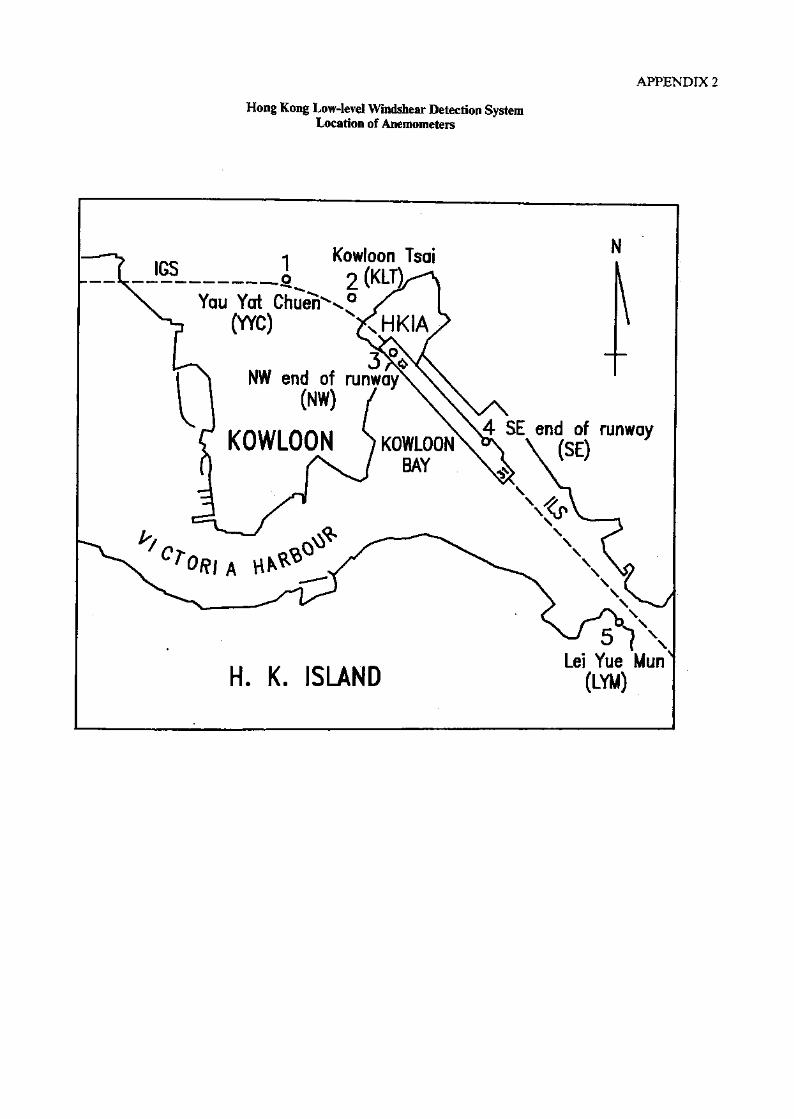
APPENDIX 2
Hong Kong Low-level Windshear Detection SystemLocation of Anemometers
Kowloon Tsai2
Yau Yat Chue>>,0
(YYC) xHKIA
NW end of runway(NW)
4 SE end of runwayHi*. m. » \ *
(SE)*:
KOWLOON KOWLOONBAY
Lei Yue Mun(LYM)H. K. SLAND

APPENDIX 3
Windshear Detection System (anemometer readings)
31-AUG-1988- WEDNESDAY 01:14:00SELYMNWYYCKLTSHEAR
A100/ 06 B100/ 07 C130/ 07 0080-160 E 00- 00 FR 04 L 04 GT t-> H 1-A030/ 09 B100/ 06 C070/ 01 12 H U
A100/ 01 B140/ 01 C110/ 02 D040-190 E 00- 00 FR 05 L OS GT OA H A/A050/ 05 B060/ 05 CQ90/ 04 • 6 H °6
A100/ 02 B140/ 02 C120/ 0231A/13D NO SHEAR +00 13A/31D SINKING .-02' QHH XXXX
31-AUG-1988 WEDNESDAY 01:14s30SE ~ A100/ 05 B100/ 06 C130/ 07 D080-160 E 00- 00 FR 04 L 04 GT 1^ H 1?
'.LYM A080/ 10 B090/ 08 C070/ 01 . ,NW A100/-01 B120/ 01 C110/ 02 D040-190 E 00- 00 FR 05 L 05 GT 06 H 06n'C A040/ 04 B050/ 05 C090/ 04KLT A090/ 02 B120/ 02 C120/ 02SHEAR 31A/13D LIFTING 4-01 - 13A/31D SINKING -02 QNH XXXX
31-AUG-1983 WEDNESDAY 01:15=00SE A090/ 06 B090/ 06 C130/ 07 DOSO-160 E 00- 00 FR 04 L 04 GT 12 H 12LYM A080/ 11 B090/ 09 CO/0/ 01NU A110/ 01 B110/ 01 C110/ 02 D040-190 £ 00- 00 FR 05 L 05 GT 06 H 06YYC A020/ 02 B040/ 04 C090/ 04KLT A100/ 08 B100/ 03 C120/ 02SHEAR 31A/13D LIFTING 4-01 13A/31D SINKING -01 QNH XXXX
31-AUG-1933 WEDNESDAY 01:15:30SE A090/ 06 B090/ 06 C130/ 07 D080-160 E 00- 00 FR "04-L 04 GT 12 H 12LYM A070/ 11 B080/ 0? C070/ 01 ''NW A110/ 01 B CALM C110/ 02 D040-190 E 00- 00 FR 05 L 05 GT 06 H 06YYC A340/ 01 B030/ 03 C090/ 04KLT A100/ 08 B100/ 04 C120/ 02SHEAR 31A/13D LIFTING 4-01 13A/31D NO SHEAR 4-00 QWH XXXX'
31-AUG-1938- WEDNESDAY 01:16 = 00SE A090/ 06 B090/ 06 C120/ 08 D070-160 E 00- 00 FR 05 L 05 QT 12 H 12LYM A070Y 10 BQBQ/ 10 C080/ 03NW A110/ 01. B CALM C120/ 02 D060-190 E 00- 00 FR 05 L 05 GT 06 H 06YYC A300/ 04 B360/ 02 C030/ 04KLT A090/ 08 B090/ 05 C130/ 03SHEAR 31A/13D LIFTING 4-01 13A/31D LIFTING 4-01 QNH XXXX
31-AUG-1983 WEDNESDAY 01:16:30SE A080/ 07 B090/ 06 C120/ 08 •0070-160 E 00- 00 FR 05 L 05 GT 12 H 12LYM A070/ 09 B080/ 10 C080/ 03NW A130/ 01 B110/ 01 C120/ 02 0060-190 E 00- 00 FR 05 L 05 GT 06 H 06YYC A290/ 04 B330/ 02 C030/ 04KLT A100/ 06 B090/ 07 C130/ 03SHEAR 31A/13D NO SHEAR 4-00 13A/31D LIFTING 4-02 QNH .XXXX
31-AUG-1988 WEDNESDAY 01:17:00SELYMNWYYCKLTSHEAR
A080Y 07 -B090/ 06 C120/ OS..0070-160 E 00- 00 FR 05 L 05 GT'12 H 12A070/ 09 B.070/ 10 C080/ 03A130/ 01 B120/ 01 C120/ 02. 0060-190 E 00- 00 FR 05 L 05 GT 06 H 06A2SO/ 04 B300/ 02 C080/.04 < :
A070/ 06 B090/ 07' C1307 03. 31A/13D NO SHEAR 4-00 13A/31D LIFTING ' 4-02 QNH XXXX
31-AUG-1988 WEDNESDAY 01:17:30SELYMNWYYCKLTSHEAR
A090/ '07 B090/ 07 C120/ 08 D070-160 E 00 -00 FR 05 L 05 GT 12 H 12A060/ 11 B070/ 09 C080/ 03 > ^/ u A140/ 01 B120/ 01 C120/ 02 D060-190 E CO- 00 FR 05 L Oo GT 06 H 06A310/ 04 B290/ 03 C030/ 04A100/ 04 B090/ 06 C130/ 03 . , vv%/v/
31A/13D- SINKING -01 13A/31D LIFTING 4-02 QNH XX/CX
/continued

E 00- 00 FR 06 L 06 GT 12 H 12
31 - A'WG -19 8 8 W E D N E 3 H A Y 01 r, 18 s 00BE A080/ 08 B090/ 07 C110/ OS B070-160LYM A040/ 08 B070/ 09 C090/ 05M A140/ 07 B130/ 01 C130/ 01 D090-190 E 00- 00 FR 05 L 05 GT 08 H 08YYC A310/ 03 B290/ 04 C050/ 04KLT A060/ 02 BOSO/ 05 C130/ 03SHEAR 31A/13D SINKING -01 13A/31D LIFTING +05 QN.H XXXX
31-AUG-1988 WEDNESDAY 01 a 18:30SELYMNWYYCKLTSHEAR
A090/ 08 B090/ 07 C110/ 08 D070-160 E 00- 00 FR 06 L 06 GT 1? H l">A050/ 09 B060/ 09 C090/ 05A140/ 07 B140/ 03 C130/ 01 D090-190 £ 00- 00 FR 05 L 05 GT 08 H 08A310/ 03 B300/ 03 C050/ 04A300/ 02 B050/ 04 C130/ 0331A/13D SINKING -03 13A/31D LIFTING QNH XXXX
31-AUG-1988 WEDNESDAY Olsl9r,00SE A100/ 10 B090/ 07 C110/ 08 D070-160LYM A030/ 08 BOSO/ 09 C090/ 05NW A140/ 06 B140/ 04 C130/ 01 D090-190YYC A340/ 02 B310/ 03 C050/ 04KLT A290/ 06 B020/ 03 C130/ 03
E 00- 00 FR 06 L 06 GT 12 H 12
E 00- 00 FR 05 L 05 GT 08 H 08
SHEAR 31A/13D SINKING -04 13A/31D LIFTING +04 QNH XXXX
31-AUG-1988 WEDNESDAY 01:19:30SELYMNWYYCKLTSHEAR
A100/ 09 B090/ 08 C110/ 08 D070-160 E 00- 00 FR 06 L 06 GT 12 H 12A360/ 05 B040/ 08 C090/ 05A130/ 04 B140/ 05 C130/ 01 D090-190 E 00- 00 FR 05 L 05 GT 08 H 08A360/ 03 B330/ 03 C050/ 04A290/ 06 B350/ 03 C130/ 03
31A/13D SINKING -05 13A/31D LIFTING +03 QNH XXXX
31-AUG-1938 WEDNESDAY 01:20:00SE A100/ 10 B090/ 08 C100/ 08 D070-140 E 00- 00 FR 07 L 07 GT 12 H 12LYM A300/ 06 B020/ 07 CO/0/ 06NW A120/ 04 B130/ 05 C130/ 02 D100-190 E 00- 00 FL 03 R 03 GT 08 H 08YYC A360/ 03 B340/ 02 C010/ 03KLT A270/ 06 B310/ 04 C160/ 04SHEAR 31A/13D SINKING -06 13A/31D LIFTING +02 QNH XXXX
31-AUG-1988 WEDNESDAY Ols20s30SE A100/ 12 B100/ 09 C100/ 08 D070-140 E 00- 00 fR 07 L" 07 GT 12 H 12LYM A270/ 03 B350/ 05 C070/ 06NW A110/ 02 B120/ 04 C130/ 02 D100-190 E 00- 00 FL 03 R 03 GT 08 H 08YYC A010/ 03 B350/ 03 C010/ 03KLT A340/ 06 B310/ 05 C1607 04SHEAR 31A/13D SINKING -07 13A/31D LIFTING +01 QNH XXXX
31-AUG-19B8 WEDNESDAY 01s21sOOSELYMNWYYCKLTSHEAR
A100/ 11 B100/ 10 C100/ 08 B070-14Q E 00- 00 FR 07 L 07 GT 12 H 12A230/ 01 B310/ 04 C070/ 06 - „ ,, A110/ 01 B120/ 03 C130/ 02•D100-190 E 00- 00 FL 03 R 03 GT 08 H 08A020/ 0.3 B360/-03. C010/ 03A360/ 05 B320/ 05 C1607 04 •31A/13D SINKING -05 13A/31D NO SHEAR +00 QNH XXXX
31-AUG-.1988 WEDNESDAY Ols21s30SE A110/ 10 B100/ 10 C100/ 08 D070-140 E 00- 00 FR 07 L 07 GT 12 H 12l-YM A010/ 01 B280/ 02 C070/ 06NW A060/ 01 B110/ 02 C130/ 02 B100-190 E 00- 00 FL 03 R 03 GT 08 H 08YYC A010/ 02 B010/ 03 C010/ 03KLT A360/ 06 B340/ 05 C160/ 04SHEAR 31A/13D SINKING -04 13A/31D NO SHEAR +00 QNH XXXX
/continued

31-AUG-1988 WEDNESDAY Ols22-:00SE A110/ 12 B100/ 10 C090/ 08 BOOO-000 E 00- 00 FR 08 L 08 GT 11 H 11LYM A360/ 03 B280/ 01 C040/ 0?NU A090/ 01 B100/ 01 C120/ 01 D060-190 E 00- 00 FL 02 R 0? GT 08 H 08YYC A010/ 02 B010/ 03 C360/ 03KLT A360/ 06 B350/ 05 C050/ 04SHEAR 31A/13D SINKING -05 13A/31D NO SHEAR +00 QNH XXXX
31-AUG-1988 WEDNESDAY 01:22=30SE A120/ 10 B110/ 10 C090/ 08 BOOO-000 E 00- 00 FR 08 i 08 GT 11 H 11LYM A350/ 07 B300/ 02 C040/ 07NU) A070/ 01 B090/ 01 C120/ 01 B060-190 E 00- 00 FL 02 R 02 GT 08 H 08YYC A350/ 03 B010/ 02 C360/ 03KLT A340/ 06 B3SO/ 06 C050/ 04SHEAR 31A/13D'SIG SINKING -08 13A/31D NO SHEAR +00 QNH XXXX
31-AUG-19S8 WEDNESDAY 01:23:00SE A120/ 10 B110/ 10 C090/ 08 BOOO-000 E 00- 00 FR 08 L 08 GT 11 H 11LYM A340/ 09 B330/ 04 C040/ 07NW A090/ 01 B080/ 01 C120/ 01 D060-170 E 00- 00 FL 02 R 02 GT 08 H 03YYC A340/ 02 B360/ 02 C360/ 03KLT A360/ 04 B350/ 06 C050/.04SHEAR 31A/13D SIG SINKING -09 13A/31D NO SHEAR +00 QNH XXXX
,31-AUG-1988 WEDNESDAY 01:23:30SE A120/ 10 B120/ 10 C090/ 08 DOOO-000 E 00- 00 FR 08 L 08 GT 11 H 11LYM A360/ 11 B350/ 06 C040/ 07NW A090/ 01 B080/ 01 C120/ 01 D060-190 E 00- 00 FL 02 R 02 GT 08 H 08YYC A320/ 03 B350/ 02 C360/ 03KLT A360/ 05 B350/ 05 C05C/ 04SHEAR 31A/13D SIG SINKING -09 13A/31D LIFTING +01 QNH XXXX
31-AUG-1988 WEDNESDAY Ols24s00SE A120/ 10 B120/ 10 C100/ 08 DOOO-000 E 00- 00 FR 08 L 08 GT 11 H 11LYM A010/ 12 B360/ 09 C020/ 07NW A100/ 04 B090/ 01 C110/ 02 D060-1SO E 00- 00 FR 04 L 04 GT 08 H 08YYC A310/ 03 B330/ 02 C340/ 03KLT A350/ 06 B350/ -05 CO207 05SHEAR 31A/13D SIG SINKING -09 13A/31D LIFTING +02 QNH XXXX
31-AUG-198S WEDNESDAY 01:24:30SE A110/ 09 B120/ 09 C100/ 08 DOOO-000 E 00- 00 FR 08 L 08 GT 11 H 11LYM, A010/ 12 B360/ 10 C020/ 07NW A100/ 05 B090/ 02 C110/ 02 D060-150 E 00- 00 FR 04 L 04 GT 08 H 08YYC A330/ 04 B320/ 02 C340/ 03KLT A320/ 05 B350/ 05 C020/ 05SHEAR 31A/13D SIG. SINKING r08 ,. 13A/31D LIFTING . +03 QNH XXXX
31-A8G-1988 WEDNESDAY 01=25:00.SE A110/ 09 B120/ 09 C100/ 08 DOOO-000 E 00- 00 FR 08 L 08 GT 11 H 11LYM A020/ 10 B360/ 11 C020/ 07NW A090/ 04 B0.907 03 C110/ 02 D060-150 E 00- 00 FR 04 L 04 GT 08 H 03YYC A330/ 06 B320/ 03 C340/ 03KLT A340/ 05 B350/ 0.5 C020/ 05SHEAR 31A/13B SINKING -07 13A/31D LIFTING +03 QNH XXXX
31-AUG-1988 WEDNESDAY Ols25s30SE A120/ 09 B120/ 09 C100/ 08 DOOO-000 E 00- 00 FR 08 L 08 GT 11 H 11LYM A020/ 0? B010/ 10 C020/ 07NW A070/ 01 B090/ 03 C110/ 02 0060-150 E" 00- 00 FR 04 L 04 GT 08 H 08YYC A330/ 06 B320/ 04 C340/ 03KLT A330/ 08 B340/ 05 C020/ 05SHEAR 31A/13D SINKING -07 13A/31D LIFTING +02 QHH XXXX

APPENDIX 4
Runway 31 ILS Approach Chart
INSTRUMENTAPPROACHCHART
114'00'E
AERODROME ELEV 15 FTHEIGHTS RELATED TO
AD ELEV'14'1Q'E
JAPP 119.1 !JTWR 118.7!
119.5J
HONG KONG INTERNATIONALILS RWY 31
(DIRECT FEED- IN)14'30'E
MNM INITIAL APCH ALT 4500(3500 WITHIN SECTOR 091"-241")
22'20N
22'10'M
114'20E
ILS approach will be monitored by PAR wheneverthe cloud ceiling is 1 000 ft or less and/or visibility5 km or less, or at the request of the pilot.
TRANSITION jALTITUDE 11000|
1H"30'E
4500(4485)
ROL 031 CHNDBSC
NDBRW
MM
VOR / NDBTH TP
OM
ELEV 15r
12
;3500 I3485JWITHIN SECTOR091'-241*
2000 (1985)MNTN TILLINTERCEPTING GP
10 0 2 4 6
NM FROM THR RWY 3.1
10 1.2 14 16
MISSED APPROACH: Climb to 2 500 ft on track 315JM towards 'RW NDB. When passing within 1 NM southeast
of '|-HK' DME and above 330 n, turn left to 'SC1 NOB and continue climb to 4 500 ft From 'SC' NDB track 255flM
to intercept 'CH* VOR 031 radial. Turn left to track 21 I'M to 'CH' VOR and join the 'CH' VOR hold or as directed
byATC.In the event 'CH* VOR is unserviceable, 'CC( NDB may be used instead. In this case, track 255°M from (SC' NDB
until 'CC' NDB bears 214°M, then turn left to track 211°M to 'CC' NDB and join 'CC' NDB hold at 4500 ft or as
directed by ATC.
Note: With GP inoperative-Cross the OM at 2 000 ft, descend as for a 3* glidepath. Do not descend below 750 ft
until 3 NM 'l-HK' DME, then continue descend to decision height.

APPENDIX 5
RTF Transcript
This transcription covers the time period from 31 August 1988,0043 UTC, to 31 August 1988, 0119 UTC. It is a true transcription of therecorded conversation pertaining to the subject accident.
Agencies making t ransmi ssions Abbr e v ia t ion s
China 301 CCA 301Hong Kong Approach APPWorld 6188 WOA 6188China 319 CCA 319Hong Kong Precision PARHong Kong Tower AMCKorean 616 KAL 616Approach Coordinator COO

Station
GCA301
APP
GCA301
APP
GGA301
CCA301
APP
CCA301
APP
CGA301
APP
CCA301
APP
Frequency
119.1
119.1
119,1
119.1
119.1
119.1
119.1
119.1
119.1
119.1
119.1
119.1
119.1
Time (UTC)
0043:28
0043:30
0043:33
0043:42
0043:48
0045:34
0045:43
0045:52
0045:54
0046:00
0047:44
0047:50
0047:52
Communication
Approach China Three Zero One good morning
China Three Zero One Hong Kong Approach good morning
China Three Zero One Lima Quebec maintain ten thousandfeet Information Delta squawk three one zero one
China Three Zero One radar contact call me again twentymiles before RUMET for instructions
China Three Zero One
Hong Kong Approach China Three Zero One deviatetwelve miles to the left due to charlie bravo
China Three Zero One Hong Kong Approach no objectionsfor your deviation call me again passing abeam RUMET
Say again please
China Three Zero One report passing abeam RITMET youcan deviate I have no objection over
Roger report abeam RUMET China Three Zero One
China Three Zero One Hong Kong
Three Zero One go ahead please
China Three Zero One on my radar there is weather betweenCharlie Hotel and Two Seven Zero Radial up to Lima Tangoif you prefer you can have Runway Three One monitored ILSApproach The surface wind is between zero nine zero to onefour zero degrees at one zero knots It's heavy showerover the airfield the visibility on Runway Three One is fivethousand metres on the IGS is three thousand metres advise
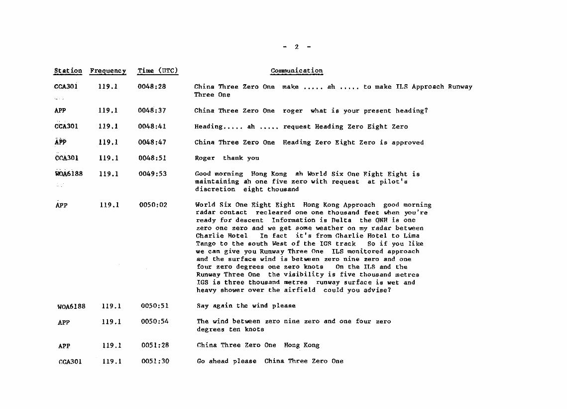
Station Frequency Time (ITTC) Communication
CCA301
APP
CCA301
APP
CCA301
WOA6188
119,1
119.1
119.1
119.1
119.1
119.1
0048:28
0048:37
0048:41
0048:47
0048:51
0049:53
APP
WOA6188
APP
APP
CCA301
119.1
119.1
119.1
119.1
119.1
0050:02
0050:51
0050:54
0051:28
0051:30
China Three Zero OneThree One
make ..... ah ..... to make ILS Approach Runway
China Three Zero One roger what is your present heading?
Heading*,... ah »,,,. request Heading Zero Eight Zero
China Three Zero One Heading Zero Eight Zero is approved
Roger thank you
Good morning Hong Kong ah World Six One Fight Eight ismaintaining ah one five zero with request at pilot'sdiscretion eight thousand
World Six One Eight Eight Hong Kong Approach good morningradar contact recleared one one thousand feet when you'reready for descent Information is Delta the QNH is onezero one zero and we get some weather on my radar betweenCharlie Hotel In fact it's from Charlie Hotel to LimaTango to the south West of the IGS track So if you likewe can give you Runway Three One ILS monitored approachand the surface wind is between zero nine zero and onefour zero degrees one zero knots On the ILS and theRunway Three One the visibility is five thousand metresIGS is three thousand metres runway surface is wet andheavy shower over the airfield could you advise?
Say again the wind please
The wind between zero nine zero and one four zerodegrees ten knots
China Three Zero One Hong Kong
Go ahead please China Three Zero One

Station Frequency Time (UTC) Communicat ion
APP
CCA301
APP
CCA301
.C0A301
APP
rrAioi\J\j£\*J v/ i
APP
ppA^m\j \jJn.-3 w •*•
APP
WOA6188
APP
APP
WOA6188
APP
CCA301
119.1
119.1
119.1
119.1
119.1
119.1
119.1
119.1
119.1
119.1
119.1
119.1
119.1
119.1
119.1
119.1
0051:32
0051:38
0051:42
0051:46
0051:52
0052:00
0052:03
0052:06
0052:09
0052:10
0052:17
0052:24
0052:43
0052:50
0052:52
0052:56
China Three Zero One in how many miles you can accept aright turn?
Er not right turn China Three Zero One
China Three Zero One roger turn right heading One Four Zero
Heading One four Zero China Three Zero One
China Three Zero One righting two minutes ..... ah ..... right
China Three Zero One say your message again?
Request in ..... two minutes right please
Confirm in two minutes you can turn right?
... mative
Roger
World Six One Eight Eight leaving ah one five zero forone one thousand
World Six One Eight Eight roger
World Six One Eight Eight ah do you prefer RunwayOne Three or Three One?
Three One ma'm
World Six One Eight Eight roger
China Three Zero One starting right turn
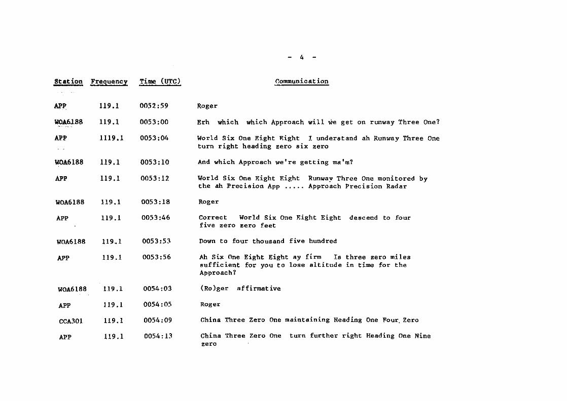
Station Frequency Tims (UTC) CommunicatIon
APP
WOA6188
APP
WOA6188
APP
WOA6188
APP
WOA6188
APP
WOA6188
APP
CCA301
APP
119,1
119.1
1119,1
119.1
119.1
119.1
119.1
119.1
119.1
119.1
119.1
119.1
119.1
0052:59
0053:00
0053:04
.0053:10
0053:12
0053:18
0053:46
0053:53
0053:56
0054:03
0054:05
0054:09
0054:13
Roger
Erh which which Approach will we get on runway Three One?
World Six One Eight Eight I understand ah Runway Three Oneturn right heading zero six zero
And which Approach we're getting ma'm?
World Six One Eight Eight Runway Three One monitored bythe ah Precision App ..... Approach Precision Radar
Roger
Correct World Six One Eight Eight descend to fourfive zero zero feet
Down to four thousand five hundred
Ah Six One Eight Eight ay firm Is three zero milessufficient for you to lose altitude in time for theApproach?
(Ro)ger affirmative
Roger
China Three Zero One maintaining Heading One Four% Zero
China Three Zero One turn further right Heading One Ninezero

81 at ion Frequency Time (UTC)
0GA301
APP
WQA6188
APP
APP
CCA301
APP
WOA6188
APP
APP
WOA6188
APP
APP
CCA301
CCA301
119,1
119.1
119.1
119 a
119.1
119.1
119,1
119.1
119.1
119,1
119.1
119.1
119.1
119,1
119,1
0054:19
0054:22
0054:26
0054:32
0055:00
0055:04
0055:14
0055:17
0055:21
0055:31
0055:42
0055:43
0055:52
0055:55
0056:29
Commun i c a t ion
Right Heading One Nine Zero stand by
China Three Zero One correct
World Six One light Eight is a little ,.,., going alittle right of track to go round build up
Six One Eight Eight ay firra'd , ....
China Three Zero One no delay for the approach keep high speed
Roger China Three Zero One
World Six One Eight Eight report passing altitude?
Just comin1 through ah one zero thousand
Ah roger
Ah World Six One Eight Eight can you accept headingzero six zero for base leg now?
'firmative
Roger heading zero six zero for base leg
China Three Zero One can you accept a right turn now?
Ah .....Stand by stand by
Hong Kong Approach China Three Zero One main....ah maintain One Four Zeroflying to . . route to abeam Tango Hotel and right turn
AFP 119.1 0056:43 Can you accept a right turn now Three Zero One?

St at ion Frequency Time (IITG)
(X1A301 119.1 0056:46
APP
APP
119.1 0056:57
CGA301
APP
WOA6188
APP
119,1
119.1
119.1
119.1
0057:01
0057:03
0057:06
0057:11
WOA6188 11.9.1 0057:14
APP 119.1 0057:16
WOA6188 119.1 0057:22
119.1 0057:28
WOA6188 119.1 0057:32
APP 119.1 0057:37
Communicat ion
Negative negative maintaining One Four Zero maintainOne Four Zero fly to abeam Tango Ho ... Tango Papa Tango Papa
Roger Three Zero One advise when you can accept a rightturn
Roger
World Six One Eight Eight check passing altitude?
Level at four thousand five hundred
World Six One Eight Eight confirm maintaining four fivezero zero?
That's affirmative Six One Eight Eight
Roger turn left heading three six zero to intercept Localizerwhen established cleared ILS Approach Runway ThreeOne
Three Six Zero's the Heading cleared to establish onLocalizer World Six One Eight Eight
Six One Eight Eight latest information from Tower thesurface wind mainly calm this time
Wind mainly calm roger
China Three Zero One Tower reports the surface wind mainlycalm this time

Station
CCA301
GCA301
APP
CCA301
APP
CCA301
CCA301
APP
APP
WOA6188
APP
CCA301
APP
CCA301
CCA301
APP
Frequency
119.1
119.1
119.1
119.1
119,1
-11.9.1
119.1
119.1
119.1
119.1
119.1
119.1
119.1
119.1
119.1
119.1
Time (UTC)
0057:42-
0059:02
0059:07
0059:10
0059:11
0059:18
0059:25
0059:30
0101:01
0101:06
0101:08
0101 :09
.0101:12
0101:16
0101:40
0101:45
Gommunicat ion
Roger China Three Zero One
Hong Kong China Three Zero One right Heading One Six Zero
Roger Three Zero One Heading One Six Zero is approved
(Ro)ger
And Three Zero One descend when ready to six thousand feetQNH one zero one zero report leaving one zero thousand
Roger China Three Zero One
China Three Zero One now leaving ten thousand feet for sixthousand feet
Roger Three Zero One
World Six One Eight Eight contact Precision One OneNiner Decimal Five for monitored approach
One One Nine Five good day ....
Goodbye
Approach China Three Zero One right Heading Two Four Zero
China Three Zero One roger turn right Heading Two Four Zero
Roger
China Three Zero One reaching six thousand feet
China Three Zero One roger maintain six thousand feet

Station Frequency
CCA301 119.1
CCA3Q1 119.1
CCA301 119,1
APP 119.1
OCA301 119,1 0102:16
APP '119.1 0102:18
CCA319 119.1 0102:35
APP 119,1
CCA319 119.1
APP 119;1
CCA319 119.1
CGA301 119.1
Time (UTC) Communicat ion
0101:47 (Ro)ger maintain
'0101:56 China Three Zero One right Heading Two Eight Zero
0102:04 Approach China Three Zero One right Heading Two Eight Zero
0102:07 China Three Zero One can you erh maintain your present headingexpect four zero miles to touch down I have one departure todepart Runway One Three ahead of you
Roger maintain present heading
Thank you
Hong Kong Approach China Three One Nine good morning-I-111.... will be one zero thousand feet RumetInformation Delta
0102:42 China Three One Nine good morning Information now isEcho QNH is One Zero One Zero Expect radar vectorsfor ILS Runway Three One and squawk ident please
0102:55 Squawk Three One One One radar vectors for ILS Runway ThreeOne QNH one zero one zero Information Echo ChinaThree One Nine
0103:13 China Three One Nine identified
0103:15 Three One Nine roger
0103:39 China Three Zero One can.... can I right Heading TwoEight Zero?
APP 119.1 0103:46 China Three Zero One confirm that is due to weather?
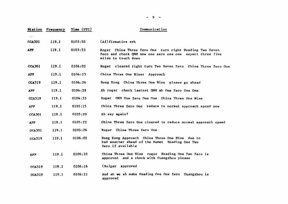
Station Frequency Time (UTC) Communicat ion
CGA301
APP
CCA3Q1
APP
CCA319
APP
CCA319
APP
CCA301
APP
COA301
CCA319
119*1
119.1
119.1
119,1
119.1
119.1
119.1
119.1
119.1
119.1
119.1
119.1
0103:50
0103:53
0104:02
0104:23
0104:26
0104:28
0104:33
0105:15
0105:20
0105:22
0105:26
0106:02
APP 119.1 0106:10
CCA319 119.1 0106:16
GCA319 119.1 0106:21
(Af)firmative erh
Roger China Three Zero One turn right Heading Two SevenZero and check QNH now one zero one one expect three fivemiles to touch down
Roger cleared right turn Two .Seven Zero China Three Zero One
China Three One Niner Approach
Hong Kong China Three One Nine please go ahead
Ah roger check lastest QNH ah One Zero One One
Roger QNH One Zero One One China Three One Nine
China Three Zero One reduce to normal approach speed now
Ah say again?
China Three Zero One cleared to reduce normal approach speed
Roger China Three Zero One
Hong Kong Approach China Three One Nine due tobad weather ahead of the Rumet Heading One TwoZero if available
China Three One Nine roger Heading One Two Zero isapproved and a check with Guangzhou please
(Ro)ger approved
And ah we ah make Heading One One Zero Guangzhou isapproved

- 10 -
Station Frequency Time (UTC)
APP 119.1 0106:27
CCA319 119.1 0106:29
APP 119.1 0106:33
CCA301 -119.1 0106:42
CCA301 119.1 0107:33
APP 119.1 0107:36
CCA301 119.1 0107:40
CCA319 119.1 0108:29
APP 119.1 0108:35
CGA319 119.1 0108:45
APP 119.1 0108:49
CCA319 119.1 0108:56
APP 119.1 0109:40
Comrounicat ion
China Three One Nine roger Hong Kong no objections
Roger thank you sir
China Three Zero One expect ah continue this heading to crossthe Localizer rejoin from the west descend to five thousandfeet
Roger descend five thousand feet maintain to presentheading China Three Zero One
Radar Three Zero One reaching five thousand feet
China Three Zero One roger maintain five thousand feet I111call you back for descent
Roger China Three Zero One
Ah Three One Nine abeam Rumet one zero thousand feet
China Three One Nine roger can you accept the ....Heading of One Three Zero?
Negative we would maintain this Heading One OneZero if available
China Three One Nine affirm maintain ah one zerothousand feet and advise if you can accept a rightturn
Roger China Three One Nine
China Three Zero One turn right now Heading Three Six Zeroto intercept the Localizer stand by for the approach

- 11 -
Station Frequency Time (UTC)
CCA301 119.1 0109-.48
APP 119,1 0109:51
CCA301 119,1 0109:57
APP 119.1 0110:02
CCA301 119.1 0110:06
APP 119.1 0110:11
KAL616 119.1 0110:18
APP 119.1 0110:20
KAL616 119.1 0110:29
Communication
Roger right turn Three Six Zero?
Correct right Heading Three Six Zero to intercept the Localizerstand by for the approach
Bequest left..request left ah
China Three Zero One can you accept a right turn Heading ThreeSix Zero now?
Negative negative request left turn request left turn due tocharlie bravo
China Three Zero One roger left turn long way round HeadingThree Six Zero
(Crossed transmissions)
Departure Korean Six One Six maintain three thousand
Korean Six One Six roger turn left now Heading ZeroNine Zero climb to five thousand feet
Roger climb five thousand feet zero nine zero SixOne Six
APP 119.1 0110:33 China Three Zero One descend to four thousand five hundred feet

Station Frequency Time (UTC)
AMC/OQO Intercom 0110:33
CCA301
APP
KAL616
APP
KAL616
APP
119.1 0110:37
119.1 -0111:12.
119.1 0111:18
119.1 0111:24
119.1 0111:42
119.1 0111:45
- 12 -
Communicat ion
COO
AMG
Go ahead
COO
AMC
COO
AMC
COO
Latest Foxtrot is opposite runway and the windis One Two Zero to One Five Zero Five toTen, runway wet and the visibility Four FiveZero Zero meters .... (cross talking)
Hang on I need to copy down One Two ZeroOne Five Zero degree Five to ten runway surface wet
Yah and the visibility is Four Five ZeroZero meters in rain
Four Five Zero Zero meters in rain
Yah
Okay
Descend four five zero zero feet China Three Zero One
Korean Six One Six continue climb to seven thousandfeet report passing five thousand
Roger Korean Six One Six continue climb to seventhousand feet report five thousand
Correct
Korean Six One Six passing five thousand
Korean Six One Six roger can you accept a rightturn Heading One Two Zero for the One Zero fourRadial?
KAL616 119.1 0111:52 Roger Heading One Two Zero for Radial One Zero Four

CCA301
APP
119.1
11-9.1
Station Frequency Time
APP 119 a 0112:21
CCA301 119.1 0112:23
APP 119.1 0112:28
0112:34
0112:41
CCA30-1
APP
CCA301
APP
CCA301
APP
119.1
119.1
•119.1
119.1-
119.1
119.1
0112:58
0113:00
0113:04
0113:07
0113:11
0113:14
APP 119.1 0114:33
- 13 -
Communicat ion
China Three Zero One your passing level?
Three Zero One four five zero-o feet Heading Three Six Zero
China Three Zero One roger Heading Three Six Zero to intercept theLocalizer you are cleared for the ILS Approach
(Ro)ger intercept the Localizer cleared for ILS ApproachChina Three Zero One
China ..correction all stations latest weather wind onetwo zero to one five zero degrees five to one zero knotsrunway surface wet visibility four thousand five hundredmetres in rain
(Ro)ger China Three Zero One
China Three Zero One confirm you accept Runway Three OneApproach?
Affirmative Runway Three One
China Three Zero One roger closing the Localizer from theleft report established
Roger report established China Three Zero One
Korean Six One Six climb now to Flight Level Three ThreeZero present heading to intercept Charlie Hotel RadialOne Zero Four
China Three Zero One I see you're established you are clearedfor the ILS Approach
CCA301 119.1 0114:37 China Three Zero One established ILS Approach can

S t a t ion Frequency Time (IJTC)
- 14 -
Communicat ion
APP 119,1 0114:42
CCA301 119.1 0114:47
APP 119 a 0115:20
CCA301 119.1 0115:24
GCA301 119.5 0115:39
PAR 119.5 0115:47
CCA301 119.5 0115:54
PAR 119.5 0115:58
AMC/PAR Intercom 0116:01
China Three Zero One expect your ILS Approach monitored byPrecision Radar
Ah thank you
China Three Zero One contact Precision One One Nine DecimalFive
On ah Nine Decimal Five China Three Zero One
Hong Kong Precision China Three Zero One established ahILS Approach Runway One Three One
China Three Zero One good morning your ILS Approach will bemonitored by Precision Radar pass advisory information onlyif required
Roger Three Zero One
Roger
AMC : Visibility is now around Three Thousand metersI don't know what's wrong with the RVR
PAR : Thanks
AMC : and the China Three Zero One clear to land
PAR : Roger

- 15 -
Station Frequency Time (UTC)
PAR 119.5 0116:46
CCA301 119,5 0116:59
PAR 119,5 0117:46
COO/AMC Intercom 0118:41
AMC/PAR Intercom 0119:30
Communicat ion
China Three Zero One I have no Precision Radar contact nocontact Surface wind is zero nine zero at seven knots youare cleared to land
(Ro)ger China Three Zero One
China Three Zero One I still have no radar contactcontinue the ILS Approach
AMC : Go ahead
COO : Check latest vis
AMC : Three Thousand meters in shower
COO : 0 Kay
AMC : Crashed
.- End of Transcript -

1£5o •L
c cm Q
sS
CDmco
CD IO m> O33 *O m
o
- oo
o _.oo
-oo
CD-CDO
0>oo
CO- Oo
O-.,oo
O —oo
O —oo
mm
_ cnoo
IDmoo
CO COH H
? 5
T) T)
^° m m
*ll13 H H
S 1 1
3 3J 3)
U» COCO COCD O
COX
cnrocn
O/,
WH
ITE
ST
OB
EW
Y
//W
ITH
CO
LL
OC
AT
m0
/*>P
CH
LIG
HT
S\
!•••••
i
WH
ITE
S
TO
BE
cncnA
MT
H C
OL
LO
CA
T
mO
CD00O
W
ax

APPENDIX 7A
Flight Data Recorder Plot
CAAC TRIDENT ACCIDENT WIND GLIDESLOPE
-10 1 2 8 14 20 26
DISTANCE(FEETxlOOO) FROM AN ARBITRARY DATUM'32

Flight Data Recorder Plot(including derived PITCH parameter)
APPENDIX 7B
2.S-,
2ooo
l.S-
o.s_
0 _2 _
10 _
S _
z« --s .
— 10 «,
0 _
200 —
52 iso
?
L9
300 — S 10°
SO -\ 180.
90 .
0 J 0 J
7\V
A
4i
2i"s
37.5 7S
TIME second*
I112.5 ISO

APPENDIX 8A
TRIDENT (B2218) AIRCRAFT ACCIDENTFLIGHT CCA 301
Wreckage Distribution and Impact Sequence
*J\ . J
IFIRE STATJ0N
"31-TT--
I I I I I
\Gross
.
A
_
•\iV '"""P^"""^*- -
/> -.iv^^c Gro""" VV — "<5^^"""""'""" ...
\A10
J' *'_
/Or
^ — Ju~/ ^RUNWAY •« (Vf^oi
LEGEND
Wreckage item
Scattered wreckage
Ground witness marks
POSITION OF OCCURRENCE
51 Right outboard flap strikes
01 Right maingear strikes
01-A No ground contact
04 Left maingear mark
A Left maingear touchdown
B Start of right flap contact
53 Deep cut on ground
C Nosegear collapse
D Left maingear collapse
IDENTIFIED WRECKAGE ITEMS
ITEM DESCRIPTIONNo.
02 Brake fan guard
03 Fragments of main wheel
05 Tyre piece; sections of main wheel07 Main gear door
08 Part of wing spar landing gear support
11 Trailing edge flap
12 Refueling valve
13 Tyre fragment
14 Falsework wing trailing edge
15 Trailing edge flap
16 Drive shaft (flap)
17 Wheel antiskid unit
19 Main wheel retaining part22 Wheel tyre
23 Main wheel tyre
ITEMNo.
DESCRIPTION
25 Main landing gear down lock link
26 Main landing gear RH, and nib # 5,
fractured wing skin
28 Nose gear
29 Refueling component
30 Main wheel tyre
31 Nose wheels and axle
32 TE OB right flap section
34 Tail cone & APU exhaust
35 Oxygen tank, No. 2 engine cowling
37 Trailing edge "wedge" inboard &
* outboard flap
38 Main wheel
41 Portion of landing edge flap & track
42 Leading edge slat

Aircraft Attitude at Time of Impact
Side Elevation
APPENDIX 8B
Runway5.23
«- 6.50
1.50 Sea LevelApproach Light
Front Elevation
Approach Light Level
Plan
\\\\\
Aircraft Track 312.5

APPENDIX 9
Flight Simulation
CAAC TRIDENT ACCIDENT WIND GLIDESLOPE
-10 2 8 14 20 26DlSTANCE(FEETxlOOO) FROM AN ARBITRART DATUM
FDR Derived Profile

APPENDIX 10
Aircraft Track Made Good
N
SCALE 0
0059:02
0101:090101:56
0102:070103:39
0106:3310 20
LEGEND
CCA301 Route of flight
_ Route normally used by inbound flights from Guangzhou for Runway 31
LQ ShilongNDB
A461 CCA301 flight plan route
R Transfer Point'Rumet'
LT Chek Lap Kok NDB
1GS Instrument Guidance System
CH Cheung Chau VOR
HKIA Hong Kong International Airport ; •
TH TathongVOR
ILS Instrument Landing System
Note: Heading Information at time shown along the route can be obtained from the transcript inAppendix 5.

APPENDIX 11
ctf
O
^
CD
<+-*CD

Crash scene - right side of aircraft

PortionSubmerged
Cabin OverwingAttendant EscapeDouble Seat Hatches
RuptureLine
FrontEmergencyExitDoor
7 8 .9-*TO*ll 12 13 I1* 15 16 17 18
CabinAttendantSeat
FlighCompartment
FrontPassengerDoor
CabinAttendantDoubleSeat
Midship OverwingPassenger EscapeDoor Hatches
LAYOUT OP.PASSENGER ACCOMMODATIONmZOX

This book is due for return or renewal on tht> >'.;U'shown unless previously recalled. Fines may heincurred for late return.
DATE DUE
. 4 - _
—t --

xomsaass
LB 363*124 H7 H90
Report on the accidentto Hawker Siddeley
1990.
[LB] 363.124 H7H90
X014Sfl2E5

Reprography by the Government Printer, Hong Kong