university of groningen nature-inspired microfluidic … 7 effect of metachronal waves abstract in...
TRANSCRIPT

University of Groningen
Nature-inspired microfluidic propulsion using magnetic artificial ciliaKhaderi, Syed Nizamuddin
IMPORTANT NOTE: You are advised to consult the publisher's version (publisher's PDF) if you wish to cite fromit. Please check the document version below.
Document VersionPublisher's PDF, also known as Version of record
Publication date:2011
Link to publication in University of Groningen/UMCG research database
Citation for published version (APA):Khaderi, S. N. (2011). Nature-inspired microfluidic propulsion using magnetic artificial cilia Groningen: s.n.
CopyrightOther than for strictly personal use, it is not permitted to download or to forward/distribute the text or part of it without the consent of theauthor(s) and/or copyright holder(s), unless the work is under an open content license (like Creative Commons).
Take-down policyIf you believe that this document breaches copyright please contact us providing details, and we will remove access to the work immediatelyand investigate your claim.
Downloaded from the University of Groningen/UMCG research database (Pure): http://www.rug.nl/research/portal. For technical reasons thenumber of authors shown on this cover page is limited to 10 maximum.
Download date: 07-06-2018

Chapter 7
Effect of metachronal waves
Abstract
In this chapter we study the effect of metachronal waves on the flow created bymagnetically-driven artificial cilia in microchannels. We use a coupled magneto-mechanical solid-fluid model that captures the physical interactions between the fluidflow, ciliary deformation and applied magnetic field. When a rotating magneticfield is applied to super-paramagnetic artificial cilia, they mimic the asymmetricmotion of natural cilia, consisting of an effective and recovery stroke. Two ways ofgenerating a metachronal motion of cilia are considered; by prescribing an externalphase difference and by applying a non-uniform magnetic field. We show that thefluid flow created by the artificial cilia is significantly enhanced in the presenceof metachronal waves and that the fluid flow becomes unidirectional. Antiplecticmetachrony is observed to lead to a considerable enhancement in flow compared tosymplectic metachrony, when the cilia spacing is small. Obstruction of flow in thedirection of the effective stroke for the case of symplectic metachrony was found tobe the key mechanism that governs this effect.
7.1 Introduction
The control of fluid flow in channels of micron-scale dimensions is essential for properfunctioning of any lab-on-a-chip device. The fluid transport in microchannels is oftenperformed by downscaling conventional methods such as syringe pumps, micropumps(Laser & Santiago, 2004; Jeon et al., 2000; Schilling et al., 2002), or by exploiting electro-magnetic fluid manipulation principles, as in electro-osmotic (Chen et al., 2003; Zenget al., 2002) and magneto-hydrodynamic (West et al., 2002) devices. In search for novelways to propel fluids at micron scales, we let nature be our guide. Nature uses hair-like structures, called cilia, attached to the surfaces of microorganisms, to propel fluidsat small length scales. The typical length of a cilium is 10 microns. Cilia beat in awhip-like asymmetric manner consisting of an effective stroke and a recovery stroke.Moreover, when many cilia operate together, hydrodynamic interactions cause themto beat out-of-phase (Gueron et al., 1997), leading to the formation of metachronalwaves, and an enhanced fluid flow (Satir & Sleigh, 1990). The specific metachronyis termed symplectic (or antiplectic) when the metachronal wave is in the same (oropposite) direction as the effective stroke. The cilia on a Paramecium exhibit antiplecticmetachrony, whereas the cilia on Opalina exhibit symplectic metachrony (Blake, 1972).
Based on Khaderi, et al. Fluid flow in microchannels due to asymmetric and out-of-phase motionof magnetically-actuated artificial cilia, Journal of Fluid Mechanics, 2011, accepted for publicationand Khaderi, et al. Magnetically-actuated artificial cilia: the effect of fluid inertia and metachrony,submitted.

60 7. Effect of metachronal waves
The asymmetric motion of natural cilia is due to the intricate interaction between thecilia microstructure (axoneme) and the internal driving force generated by ATP-enabledconformational changes of the motor protein dynein. It is a challenging task to design theartificial counterpart of natural cilia, by using external force fields for actuation in orderto mimic the asymmetric motion of natural cilia. An early attempt to create artificial ciliawas based on electrostatic actuation of cilia-like microactuator arrays (den Toonder et al.,2008). Although effective flow and mixing were achieved, movement of these artificialcilia was not asymmetric as in the case of natural cilia. It was predicted using numericalsimulations that an array of identical super-paramagnetic or permanently magnetic two-dimensional plate-like cilia can mimic the planar asymmetric motion of natural cilia whenexposed to a uniform magnetic field (Khaderi et al., 2009). These magnetic artificial ciliacan be realised, for instance, by using polymer films with embedded super-paramagnetic(or permanently magnetic) nano-particles (see e.g. Fahrni et al., 2009; Belardi et al.,2010; Schorr et al., 2010). In contrast with the plate-like cilia, rod-like structures thatmimic the three-dimensional motion of nodal cilia to create fluid propulsion have alsobeen fabricated (Vilfan et al., 2010; Shields et al., 2010; Evans et al., 2007). In (Singet al., 2010), a novel method of fluid propulsion based on magnetic walkers was presented.Artificial cilia based on photo-actuation have also been realised in the recent past (vanOosten et al., 2009).
In previous studies we focused on the flow created by an array of synchronously-beating cilia whose motion is planar and asymmetric, in the absence (Khaderi et al.,2009) and presence of fluid inertia (Khaderi et al., 2010). Using numerical simulationsit was reported that a substantial but fluctuating flow is created in the former, whilein the latter the flow increases significantly as the Reynolds number is increased. Inaddition, the fluid flow can become unidirectional in the presence of fluid inertia. In thiswork we explore another aspect of natural ciliary propulsion - the metachronal motionof cilia, by allowing the asymmetrically-beating artificial cilia to move out-of-phase. Theout-of-phase motion of the cilia is achieved by applying a magnetic field that has a phaselag between adjacent cilia. The existing literature on the metachronal motion of naturalcilia could provide insights on the flow generated in the presence of metachronal waves.
In the case of natural cilia the metachronal motion is analysed principally for tworeasons. First, to find the effect of the metachronal waves on the flow created andsecond, to find the physical origin of the metachronal waves. Theoretical and numericalstudies have been undertaken by biologists and fluid mechanicians to understand the flowcreated by an array of cilia (see for e.g. the reviews by Brennen & Winet, 1977; Blake &Sleigh, 1974; Smith et al., 2008). Most of these analyses have been performed to modelthe flow of specific biological systems (e.g. microorganisms or airway cilia), however, asystematic study is lacking. In the following, we outline a number of studies in whichthe effect of the metachronal waves on fluid transport has been studied. Modellingapproaches to understand the cilia-driven flow include the envelope model (Brennen &Winet, 1977; Blake, 1971a,c), the sublayer model (Blake, 1972; Gueron et al., 1997;Smith et al., 2007; Liron, 1978; Gauger et al., 2009; Gueron & Levit-Gurevich, 1999),fluid-structure interaction models using a lattice-Boltzmann approach (Kim & Netz,2006), and the immersed boundary method (Dauptain et al., 2008). In the envelopemodel, the cilia are assumed to be very densely spaced so that the fluid experiences anoscillating surface consisting of the tips of the cilia. The envelope model is accurateonly when the cilia are spaced very close together, which has only been observed in thecase of symplectic metachrony (Blake, 1971a,c). In the sublayer model (Blake, 1972),

7.1. Introduction 61
the cilia are represented by a distribution of Stokeslets with appropriate mirror imagesto satisfy the no-slip condition on the surface to which the cilia are attached. Thesublayer model predicts that for an organism that exhibits antiplectic metachrony, theflow created is lower than for cilia beating in-phase. In the case of an organism exhibitingsymplectic metachrony, the opposite trend is observed. In the numerical study of (Gaugeret al., 2009), the flow due to the out-of-phase motion of a finite number of magneticcilia subjected to an oscillating external magnetic field was studied. The magnetic ciliagenerate an asymmetric motion due to the difference in the speed of oscillation of themagnetic field during the effective and recovery strokes. In contrast to (Blake, 1972), itwas predicted that the flow in the case of antiplectic metachrony is larger than the flowcreated by a symplectic metachrony for a particular inter-cilia spacing.
Early experiments indicated that the hydrodynamic coupling between cilia could bethe cause for the formation of the metachronal waves (see for e.g. the review by Kinosita& Murakami, 1967). By mimicking the ciliary motion of Paramecia using an internalactuation mechanism, it was demonstrated that cilia, which were initially beating in-phase, will form an antiplectic metachronal wave after a few beat cycles (Gueron et al.,1997). This behaviour was explained to be an outcome of the hydrodynamic interactionsbetween neighbouring cilia. Similar hydrodynamically-caused metachronal motion of thecilia was also observed by (Mitran, 2007). In (Gueron & Levit-Gurevich, 1999), it wasreported that in the presence of the metachronal wave the cilia become more efficient increating flow. The synchronization and phase locking of the cilia have also been analysedusing simple experimental (Qian et al., 2009) and analytical (Niedermayer et al., 2008;Vilfan & Julicher, 2006) models. It was found that some degree of flexibility is requiredfor the phase locking of the cilia to take place (Niedermayer et al., 2008; Qian et al.,2009). The requirement of the flexibility for synchronization is also confirmed from themore detailed model of (Kim & Netz, 2006). In the aforementioned studies, however, themetachronal wave is an outcome of that specific system, and the flow or the efficiencyhas not been studied for different types of metachronal waves.
The goal of this chapter is, therefore, to obtain a full understanding of the dependenceof flow on the magnetically-induced out-of-phase motion of an array of asymmetricallybeating artificial cilia. We will answer the following questions using a coupled solid-fluidmagneto-mechanical model. How does the generated flow in the presence of metachronydiffer from the flow generated by cilia that beat in-phase? How does the flow dependon the metachronal wave speed and its direction, and how does it depend on the ciliaspacing? We answer these questions in the light of magnetic artificial cilia which exhibitan asymmetric motion and beat out-of-phase. However, the results are equally applicableto any ciliary system in which the cilia exhibit an asymmetric and out-of-phase motion.
The out-of-phase motion of artificial cilia can be achieved by applying a non-uniformmagnetic field that travels in space and time. However, a non-uniform magnetic fieldwill also cause magnetic body forces to act on the cilia, which will lead to a beat motionthat is different compared to that of synchronously beating cilia. Therefore, we studythe out-of-phase motion of the cilia in two steps. First, we apply a rotating magneticfield that is uniform over each cilia but has a phase difference between neighbouringcilia. This keeps the asymmetric motion of the cilia nearly unaltered, and enables us toidentify the physical mechanisms that are operative when the cilia beat out-of-phase. Inthe second step, we apply a non-uniform magnetic field to the cilia and study how thebody forces influence the beat motion of the cilia and the resulting flow.
The chapter is organised as follows. The boundary value problem and the solution

62 7. Effect of metachronal waves
(a) (b)
Figure 7.1: (a) Schematic representation of the problem analysed. We study an infinitely long
microfluidic channel consisting of equal-sized cilia spaced a distance a apart. The variation of
magnetic field in space is shown using blue arrows. Qp and Qn denote the flow in the direction
of the effective and recovery stroke, respectively. (b) Typical asymmetric motion of a cilium.
The dashed lines represents the trajectory of the tip of an individual cilium.
methodology are explained in section 7.2.1. In section 7.2.1, the physical mechanismsresponsible for the enhanced flow in the presence of metachronal waves are discussed.The quantitative variation of the flow as a function of the phase difference and ciliaspacing is given. The deformation of the cilia due to the non-uniform magnetic field andthe resulting flow are studied in section 7.2.2. Finally, the outcome of the analysis issummarised in section 7.3.
7.2 Results
7.2.1 Externally imposed out-of-phase motion
We study the flow in an infinitely long channel of height H created by a two-dimensionalarray of magnetic artificial cilia, which are actuated using a rotating magnetic fieldwhich is uniform over each cilium, but with a phase difference between adjacent cilia.The external magnetic field experienced by the ith cilium is
Bxi = B0 cos(ωt− φi), Byi = B0 sin(ωt− φi), (7.1)
where B0 is the magnitude of the applied magnetic field, the phase of the magnetic fieldφi = 2π(i − 1)/n, ω = 2π/tref is the angular frequency and tref is the time period ofrotation of the magnetic field. The magnetic field experienced by the individual ciliaduring a particular instance in time is shown using the blue arrows in Fig. 7.1(a). Thephase difference in the applied magnetic field between adjacent cilia is ∆φ = 2π/n. Thechosen form of the phase φi makes the phase of the magnetic field at every nth ciliumidentical. That is, the magnetic field is periodic after n repeats of cilia. Consequently,the applied magnetic field travels n cilia units in time tref, so that the phase velocity ofthe magnetic field is n/tref = ω/∆φ (in cilia per second). The phase velocity is to theright (positive) and the magnetic field at each cilium position rotates counterclockwisewith time. The typical asymmetric motion of a cilium is shown in Fig. 7.1(b). The ciliaare tethered at one end to the surface, while the other end is free. The trajectory of thefree end of a typical cilium is represented by the dashed lines in Fig. 7.1(b), with thearrows representing the direction of motion.

7.2. Results 63
Due to the super-paramagnetic (SPM) nature of the cilia, for which the magnetizationis proportional to the magnetic field, the magnetic body couple (N = M ×B0, whereM is the magnetization of the cilia and B0 = (Bx, By) is the magnetic field experiencedby the cilia) depends only on the orientation and magnitude of the magnetic field, butnot on its sign. As a result, the body couple at the ith cilium Nzi, which determines itsmotion, scales with sin (2ωt− 2φi) (see Eqn. 2.37). This has consequences for the motionof the cilia, both temporally and spatially. Temporally, the frequency of the magneticcouple is twice that of the applied magnetic field. This results in two cilia beats for one360◦ rotation of the magnetic field. Spatially, the phase of the magnetic couple is twicethat of the applied magnetic field, so that the phase difference between neighbouring ciliais twice as large. This means that the magnetic couple is periodic after n/2 cilia. Sinceboth the frequency and phase difference increase by a factor 2, the phase velocity of themagnetic torque remains equal to that of the magnetic field, i.e. ω/∆φ. Note, however,that the phase velocity of the magnetic torque is equal to the velocity of the metachronalwave (i.e., the actually observed deformational wave travelling over the cilia) only whenthe phase difference ∆φ is small (i.e. n is large).
When the phase difference is too large, the metachronal wave can change sign, so thatthe metachronal wave is observed to travel in a direction opposite to the direction of themagnetic field (see appendix J). The metachronal wave velocity is equal to ω/∆φ (i.e. tothe right) when 0 < ∆φ < π/2, and it is equal to −ω/(π − ∆φ) (i.e. to the left) whenπ/2 < ∆φ < π, see Fig. 7.2. When ∆φ = 0, the magnetic couple is uniform and all ciliabeat in-phase. When ∆φ = π, the magnetic couple acting on two neighbouring cilia isthe same (because the phase difference of the magnetic couple is 2∆φ = 2π), and again,all the cilia beat in-phase. When ∆φ = π/2, the positive metachronal wave velocity isequal in magnitude to its negative counterpart. In such a condition, a standing wave isobserved which causes the adjacent cilia to move in anti-phase. When 0 < ∆φ < π/2the metachronal wave velocity is positive, i.e. to the right in Fig. 7.1. Consequently,the metachronal wave velocity is opposite to the direction of the effective stroke, whichis commonly addressed as antiplectic metachrony (AM). When π/2 < ∆φ < π, themetachronal wave velocity is in the same direction as the effective stroke and is referredto as symplectic metachrony (SM), see Fig. 7.2.
We model the cilia as elastic Euler-Bernoulli beams taking into consideration geo-metric non-linearity and inertia of the cilia in a Lagrangian framework. The magneticfield is calculated by solving the Maxwell’s equations using a boundary element approachfor each ciliary configuration (see chapter 2). The Stokes equations, which capture thebehaviour of the fluid flow at low Reynolds numbers, are solved within an Eulerian set-ting for the velocity and pressure using finite elements. The velocity is interpolatedquadratically, while the pressure is interpolated linearly within each element. The solid-fluid coupling is performed by imposing the no-slip condition at the nodal points of theEuler-Bernoulli beam elements using Lagrange multipliers (point collocation method)within a fictitious domain framework (van Loon et al., 2006). The solution procedureis as follows. The Maxwell’s equations are solved at every time instant to solve for themagnetic field. From the magnetic field, the magnetic body couple acting on the cilia iscalculated and is provided as an external load to the implicitly-coupled solid-fluid model,which simultaneously solves for the cilia velocity, and the velocity and pressure of thefluid. The velocity of the cilia is integrated using Newmark’s algorithm to obtain its newposition, and the procedure is repeated. For more details on the numerical model thereader is referred to chapter 2. Each cilium is discretised into 40 elements and every fluid

64 7. Effect of metachronal waves
Phase difference∆φ in units ofπMet
achr
onal
wav
eve
loci
tyin
units
ofω/π
0 0.2 0.4 0.6 0.8 1-10
-5
0
5
10
AM SM
In-phase
In-phase
Out-of-phase
Anti-phase
Out-of-phase
Figure 7.2: Metachronal wave velocity as a function of the phase difference ∆φ in the mag-
netic field between adjacent cilia. AM and SM refer to antiplectic and symplectic metachrony
respectively.
Per
iodi
c
No−slip
No−slipW
H
Per
iodi
c
Solid mesh
Fluidmesh
Figure 7.3: Fluid and solid mesh used for the simulations. The mesh corresponds to ∆φ = π/6
and a = 1.67L.
domain of size a ×H is discretised into 28 × 30 elements, with the mesh being refinednear each cilium. A typical mesh used for the simulations is shown in Fig. 7.3. A fixedtime-step of 1 µs is used. The particles and streamlines are obtained from the velocityfield in the fluid using the visualization software Tecplot (Tecplot, 2008).
The physical dimensionless numbers that govern the behaviour of the system are themagneto-elastic number Mn = 12B2
0L2/µ0Eh
2 - the ratio of the magnetic to the elasticforces, the fluid number Fn = 12µL3/Eh3tbeat - the ratio of viscous forces acting on thecilia to the elastic forces, and the inertia number In = 12ρL4/Eh2t2beat - the ratio of theinertia forces of the cilium to its elastic forces, (see Khaderi et al., 2009). Here, E isthe elastic modulus of the cilia, h is the thickness, ρ is the density of the cilia, µ is thefluid viscosity, tbeat(= tref/2) is the time period of one beat cycle and µ0 is the magneticpermeability. The geometric parameters that govern the behaviour of the system are thephase difference ∆φ, the cilia spacing a, their length L and the height of the channelH . We study the flow created as a function of the cilia spacing a (normalised with thelength L) and the phase difference ∆φ for the following set of parameters: Fn = 0.15,Mn = 12.2, In = 4.8 × 10⁻³ and H/L = 2. The values of the physical parameterscorrespond to L = 100 microns, E = 1 MPa, the thickness of cilia being h = 2 µm atthe fixed end and 1 µm at the free end, ρ = 1600 kg/m3, µ = 1 mPas, B0 = 22.6 mTand the cycle time tref = 20ms. The magnetic susceptibilities of the cilia are 4.6 along

7.2. Results 65
the length and 0.8 along the thickness (van Rijsewijk, 2006).
The fluid propelled is characterised by two parameters: the net volume of the fluidtransported during a ciliary beat cycle and the effectiveness. The horizontal velocity fieldin the fluid at any x position, integrated along the channel height gives the instantaneousflux through the channel. This flux integrated in time over the effective and recoverystroke gives the positive (Qp) and negative (Qn) flow, respectively (see Fig. 7.1). Due tothe asymmetric motion, the positive flow is larger than the negative flow, generating anet area flow per cycle (Qp−Qn) in the direction of the effective stroke. The effectiveness,defined as (Qp − Qn)/(Qp + Qn), indicates which part of the totally displaced fluid iseffectively converted into a net flow. An effectiveness of unity represents a unidirectionalflow. For each value of a/L, we choose n to be a fraction p/q larger than 2, with p andq integers, yielding a range of phase differences ∆φ = 2π/n between 0 and π. For eachvalue of p/q, a unit-cell of width W = pa needs to be chosen to account for periodicityin the magnetic couple, unless p is an even integer, for which W = pa/2 suffices. Forexample, let p = 10 and q = 3. Now, n = 10/3 and the phase difference ∆φ is equal to3π/5. To maintain periodicity in the magnetic couple, the width of the unit-cell shouldbe 5a (containing 5 cilia). The top and bottom of the unit-cell are the channel walls, onwhich no-slip boundary conditions are applied, while the left and right ends are periodicin velocity.
Results and discussion
To obtain an understanding of fluid flow due to the out-of-phase motion of cilia, weanalyse the case of antiplectic metachrony with a phase difference ∆φ = 2π/n = 2π/12.Since n is even, a unit-cell of width 6a consisting of 6 cilia is chosen, see Fig. 7.4. Thecontours represent the absolute velocity normalised with L/tbeat. The direction of thevelocity field can be determined from the arrows on the streamlines. The white arrowsrepresent the applied magnetic field for each cilium.
The snapshots shown in Figs. 7.4(a)-7.4(f) correspond to the time instances whenthe flux generated by the cilia is maximum. In Fig. 7.4(g) the instantaneous flux as afunction of time t (right axis) in addition to the flow (accumulated flux at time t, leftaxis) are plotted. The time instances corresponding to Figs. 7.4(a)-7.4(f) are marked inFig. 7.4(g). The motion of the fluid particles near the third cilium under the influenceof the velocity field caused by the ciliary motion is also shown. It can be observed fromFig. 7.4(g) that one beat cycle consists of six sub-beats, which correspond to the travelingof the magnetic couple from one cilium to the next. The traveling of the metachronalwave to the right can, for instance, be seen by looking at the cilia which exhibit therecovery stroke (i.e. cilium 1 in Fig. 7.4(a), cilium 2 in Fig. 7.4(b), etc). The negativeflow created by the cilia during their recovery stroke is overcome by the flow due to theeffective stroke of the rest of the cilia; this leads to a vortex formation near the ciliaexhibiting their recovery stroke. As a result, the negative flow is completely obstructedfor most of the time during the recovery stroke. It can be observed from Fig. 7.4(g) thatno flux (right axis) is transported in the negative direction, and that the flow (left axis)continuously increases during each sub-beat. Moreover, the increase in the flow duringeach sub-beat is similar (see Fig. 7.4(g)). Thus, the total flow per beat cycle (left axisof Fig. 7.4(g)) is the sum of the flows generated during each sub-beat (i.e. flow per beat= 6×flow generated during one sub-beat). Therefore, it is sufficient to analyse the fluidflow during one sub-beat.

66 7. Effect of metachronal waves
(a) t = 0
(b) t = tbeat/6
(c) t = 2tbeat/6
(d) t = 3tbeat/6
(e) t = 4tbeat/6
(f) t = 5tbeat/6
(g)
Normalisedabsolute velocity
21.751.51.2510.750.50.250
Figure 7.4: (a)-(f) Out-of-phase motion of cilia during a representative cycle for ∆φ = π/6
(n = 12) with the wave moving to the right (antiplectic metachrony) for a/L = 1.67. The
contours represent the absolute velocity normalised with L/tbeat. The direction of the velocity
is represented by streamlines. The white circles represent fluid particles. The applied magnetic
field at each cilium is represented by the white arrows. (g) Instantaneous flux (right axis) and
flow (or accumulated flux, left axis) as a function of time with the instants (a)-(g) duly marked.
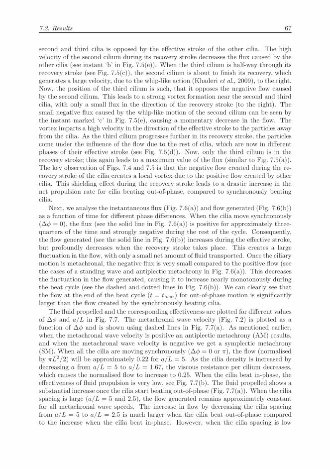
In the following, we analyse the fluid motion and the resulting flow during the sec-ond sub-beat. The velocity profiles at different instants of this sub-beat are shownin Figs. 7.5(a)-7.5(d). The corresponding flow and the flux generated are shown inFig. 7.5(e). At tbeat/6, the third cilium starts its recovery stroke and the particlesnear the top boundary are driven by the positive flow created by cilia 4, 5 and 6 (seeFig. 7.5(a)). At this instant, as only one cilium is exhibiting a recovery stroke, the fluxcreated by the cilia is maximum (see instant ‘a’ in Fig. 7.5(e)). In Fig. 7.5(b), the thirdcilium also has begun its recovery stroke and now the negative flow caused by both the
7.2. Results 67
second and third cilia is opposed by the effective stroke of the other cilia. The highvelocity of the second cilium during its recovery stroke decreases the flux caused by theother cilia (see instant ‘b’ in Fig. 7.5(e)). When the third cilium is half-way through itsrecovery stroke (see Fig. 7.5(c)), the second cilium is about to finish its recovery, whichgenerates a large velocity, due to the whip-like action (Khaderi et al., 2009), to the right.Now, the position of the third cilium is such, that it opposes the negative flow causedby the second cilium. This leads to a strong vortex formation near the second and thirdcilia, with only a small flux in the direction of the recovery stroke (to the right). Thesmall negative flux caused by the whip-like motion of the second cilium can be seen bythe instant marked ‘c’ in Fig. 7.5(e), causing a momentary decrease in the flow. Thevortex imparts a high velocity in the direction of the effective stroke to the particles awayfrom the cilia. As the third cilium progresses further in its recovery stroke, the particlescome under the influence of the flow due to the rest of cilia, which are now in differentphases of their effective stroke (see Fig. 7.5(d)). Now, only the third cilium is in therecovery stroke; this again leads to a maximum value of the flux (similar to Fig. 7.5(a)).The key observation of Figs. 7.4 and 7.5 is that the negative flow created during the re-covery stroke of the cilia creates a local vortex due to the positive flow created by othercilia. This shielding effect during the recovery stroke leads to a drastic increase in thenet propulsion rate for cilia beating out-of-phase, compared to synchronously beatingcilia.
Next, we analyse the instantaneous flux (Fig. 7.6(a)) and flow generated (Fig. 7.6(b))as a function of time for different phase differences. When the cilia move synchronously(∆φ = 0), the flux (see the solid line in Fig. 7.6(a)) is positive for approximately three-quarters of the time and strongly negative during the rest of the cycle. Consequently,the flow generated (see the solid line in Fig. 7.6(b)) increases during the effective stroke,but profoundly decreases when the recovery stroke takes place. This creates a largefluctuation in the flow, with only a small net amount of fluid transported. Once the ciliarymotion is metachronal, the negative flux is very small compared to the positive flow (seethe cases of a standing wave and antiplectic metachrony in Fig. 7.6(a)). This decreasesthe fluctuation in the flow generated, causing it to increase nearly monotonously duringthe beat cycle (see the dashed and dotted lines in Fig. 7.6(b)). We can clearly see thatthe flow at the end of the beat cycle (t = tbeat) for out-of-phase motion is significantlylarger than the flow created by the synchronously beating cilia.
The fluid propelled and the corresponding effectiveness are plotted for different valuesof ∆φ and a/L in Fig. 7.7. The metachronal wave velocity (Fig. 7.2) is plotted as afunction of ∆φ and is shown using dashed lines in Fig. 7.7(a). As mentioned earlier,when the metachronal wave velocity is positive an antiplectic metachrony (AM) results,and when the metachronal wave velocity is negative we get a symplectic metachrony(SM). When all the cilia are moving synchronously (∆φ = 0 or π), the flow (normalisedby πL2/2) will be approximately 0.22 for a/L = 5. As the cilia density is increased bydecreasing a from a/L = 5 to a/L = 1.67, the viscous resistance per cilium decreases,which causes the normalised flow to increase to 0.25. When the cilia beat in-phase, theeffectiveness of fluid propulsion is very low, see Fig. 7.7(b). The fluid propelled shows asubstantial increase once the cilia start beating out-of-phase (Fig. 7.7(a)). When the ciliaspacing is large (a/L = 5 and 2.5), the flow generated remains approximately constantfor all metachronal wave speeds. The increase in flow by decreasing the cilia spacingfrom a/L = 5 to a/L = 2.5 is much larger when the cilia beat out-of-phase comparedto the increase when the cilia beat in-phase. However, when the cilia spacing is low
68 7. Effect of metachronal waves
(a) t = tbeat/6
(b) t = 0.25tbeat
(c) t = 0.316tbeat
(d) t = 2tbeat/6
(e)
Normalisedabsolute velocity
21.751.51.2510.750.50.250
Figure 7.5: (a)-(d) Snapshots for the out-of-phase motion of cilia between time instances of
Figs. 7.4(b) and 7.4(c) for ∆φ = π/6 (n = 12) with the wave moving to the right (antiplectic
metachrony) for a/L = 1.67. The contours represent the absolute velocity normalised with
L/tbeat. The direction of the velocity is represented by streamlines. The white circles represent
fluid particles. The applied magnetic field at each cilium is represented by the white arrows.
(e) Instantaneous flux (right axis) and flow (left axis) as a function of time with the instances
(a)-(d) duly marked.
(a/L = 1.67), we see a larger increase in the fluid flow when there is an antiplecticmetachrony(AM) compared to a symplectic metachrony (SM). Also, the effectivenesssharply increases from around 0.3 (i.e., 30% of the totally displaced fluid is convertedinto net flow) to 1 (fully unidirectional flow), see Fig. 7.7(b). To analyse these trends abit further, we plot the positive and negative flow (Qp and Qn in Fig. 7.1) created duringa beat cycle for different phase differences in Fig. 7.8(a). It can be seen that the cilia donot create a negative flow when they beat out-of-phase for all cilia spacings, resulting ina unidirectional flow (effectiveness = 1). This reduction in negative flow is due to theshielding of flow during the recovery stroke caused by the effective flow of other cilia. Itcan also be noted that the positive flow is also reduced compared to in-phase beating,but the reduction is considerably less than the reduction in negative flow. Thus, the netflow increases as soon as the cilia start to beat out-of-phase (see Fig. 7.7(a)). It can beseen from Fig. 7.8(a) that in the presence of metachronal waves when the cilia spacingis large (a/L = 5), the fluid transported during the effective stroke remains nearly thesame for all values of the wave velocities. For small cilia spacing (a/L = 1.67), however,the positive flow is maximal for antiplectic metachrony, which leads to a larger net flow

7.2. Results 69
t/tbeat
Flu
x/(π
L2 /2
t beat)
0 0.5 1
-8
-6
-4
-2
0
0π/2π/6
∆φNo metachrony
Standingwave
Antiplecticmetachrony
(a)
t/tbeat
Flo
w/(π
L2 /2
)
0 0.5 10
0.1
0.2
0.3
0.4
0.5
0.6
(b)
Figure 7.6: (a) Normalised fluid flux as a function of time for a/L = 1.67 and different values
of phase difference ∆φ. (b) Normalised accumulated flow at any time t during the beat cycle.
Phase difference∆φ in units ofπ
Flo
wpe
rcy
cle/
(πL2 /2
)
Met
achr
onal
wav
eve
loci
tyin
units
ofω/π
0 0.2 0.4 0.6 0.8 1
0.2
0.4
0.6
-10
0
10Wave velocity
AM SM
(a) Area flow
Phase difference∆φ in units ofπ
Effe
ctiv
enes
s
0 0.2 0.4 0.6 0.8 10
0.2
0.4
0.6
0.8
1
a/L = 5a/L = 2.5a/L = 1.67
AM SM
(b) Effectiveness
Figure 7.7: Flow and effectiveness as a function of the phase difference ∆φ for different inter-
cilium spacings a/L. AM and SM refer to antiplectic metachrony (the wave direction is opposite
to the direction of the effective stroke) and symplectic metachrony (the wave direction and the
effective stroke direction are the same), respectively.
for antiplectic metachrony compared to symplectic metachrony.
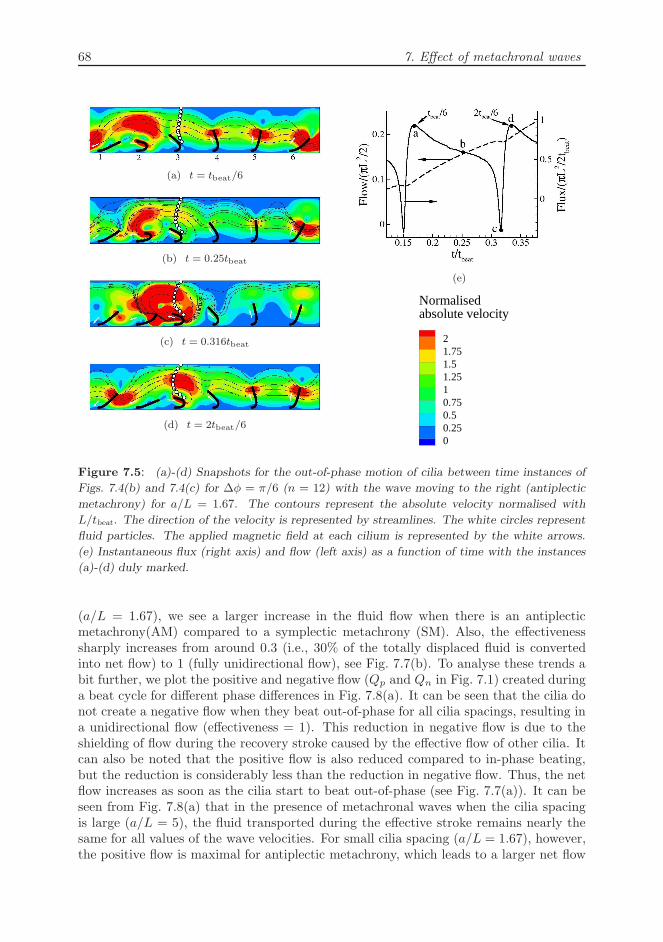
To understand the difference in positive flow for opposite wave directions for smallinter-cilium spacing (a/L = 1.67), we plot the flux as a function of time scaled withthe time taken by the magnetic couple to travel from one cilium to the next t1, for twodifferent metachronal wave velocities (3/tbeat and 6/tbeat cilia per second), see Fig. 7.8(b).The corresponding phase differences are also shown in the legend. It can be seen thatthe flux in the case of antiplectic metachrony is larger than the flux created by thesymplectic metachrony for the same wave speed. This difference in flux for opposite wavedirections can be understood by analysing the velocity field corresponding to symplecticand antiplectic metachrony at time instances when the flux is maximum (see Fig. 7.9).Figure 7.9(a) and 7.9(b) correspond to different phase differences (∆φ = π/6 and ∆φ =

70 7. Effect of metachronal waves
Phase difference∆φ in units ofπ
Flo
wpe
rcy
cle/
(πL2 /2
)
0 0.2 0.4 0.6 0.8 1
0
0.2
0.4
0.6
Positive flow (Qp)Negative flow (Qn)
a = 5La = 2.5La = 1.67L
AM SM
(a)
t/t1
Flu
x/(π
L2 /2
t 1)
0 0.5 1
-0.4
-0.2
0
0.2
0.4
π/65π/6π/32π/3
6/tbeat
3/tbeat
∆φSymplecticmetachrony
Antiplecticmetachrony
(b)
Figure 7.8: (a) Positive (Qp) and negative flow (Qn) (see Fig. 7.1) created by the cilia
corresponding to the results presented in Fig. 7.7. (b) Flux vs time (scaled with the time t1taken by the magnetic couple to travel from one cilium to the next) for a/L = 1.67 and different
wave speeds.
5π/6, respectively) leading to a similar wave speed of 6/tbeat cilia per second (see alsoFig. 7.2). The fifth cilium is in the peak of its effective stroke for both AM and SM. In thecase of symplectic metachrony, the positive flow created by the fifth cilium is obstructedby the close proximity of the fourth cilium, which has just started its effective stroke.As a result, we observe the formation of a vortex. In the case of antiplectic metachrony,however, the position of the fourth cilium is such that the positive flow created by thefifth cilium is not obstructed. This leads to larger fluid flow in the positive direction, sothat the net flow created by an antiplectic metachrony is larger than that created by itssymplectic counterpart.
Reports on metachrony and phase locking of beating cilia have appeared in the past(Gauger et al., 2009; Kim & Netz, 2006; Gueron et al., 1997; Gueron & Levit-Gurevich,1999). The main results are that metachrony enhances flow compared to synchronouslybeating cilia (Kim & Netz, 2006; Gauger et al., 2009) and that antiplectic metachronygenerates a higher flow rate than symplectic metachrony (Gauger et al., 2009). (Kim &Netz, 2006) analysed two cilia, which are driven by internal motors and are moving out-of-phase due to the hydrodynamic interaction. They have shown that the fluid propulsionincreases, once the cilia start to beat with a phase difference, which is in agreement withour results. Our results also agree with (Gauger et al., 2009), where it is shown thatthe fluid flow is larger in the case of antiplectic metachrony than symplectic metachronywhen the cilia are close together. However, our results differ from (Gauger et al., 2009)in the sense that we always see an enhancement in flow in the presence of metachrony(compared to cilia beating in-phase) irrespective of the direction and magnitude of themetachronal wave velocity. This is most likely due to the fact that the asymmetryin ciliary motion in our case is much higher. (Gueron et al., 1997) and (Gueron &Levit-Gurevich, 1999) have proposed that the evolution of the out-of-phase motion ofcilia in Paramecia is due to hydrodynamic interactions between adjacent cilia leadingto antiplectic metachrony. It is interesting to observe that the interplay between theinternally-driven actuation and hydrodynamic interaction in nature results in antiplectic
7.2. Results 71
1 2 3 4 5 6
(a) Antiplectic metachrony: wave travels to the right
61 2 3 4 5
(b) Symplectic metachrony: wave travels to the left
Figure 7.9: (Colour online) Snapshots for antiplectic (∆φ = π/6) and symplectic metachrony
(∆φ = 5π/6) for a wave speed of 6/tbeat cilia per second and cilia spacing a/L = 1.67 at
t = 0.1t1 of Fig. 7.8(b). The contours represent the absolute velocity normalised with L/tbeat
(blue and red colours represent a normalised velocity of 0 and 2, respectively). The direction
of the velocity is represented by streamlines. The applied magnetic field is shown by the white
arrows.
metachrony. Our results, and those of others (Gauger et al., 2009), show that indeedantiplectic metachrony leads to larger flow than symplectic metachrony for small ciliaspacings as typically seen in nature.
7.2.2 Out-of-phase motion caused by a non-uniform magnetic
field
Problem statement
We now study the flow generated by magnetic artificial cilia, which are actuated usinga rotating and non-uniform magnetic field (B0 = (Bx0, By0)) that varies in space andtime:
Bx0 = B0 cos(ωt± 2πx/λ), By0 = B0 sin(ωt± 2πx/λ), (7.2)
where B0 is the magnitude of the applied magnetic field, λ the wavelength of the non-uniform magnetic field, ω = 2π/tref is the angular frequency and tref is the time periodof the magnetic field, see Fig. 7.10. The applied magnetic field travels in space and timewith a velocity λ/tref, which is positive (i.e., to the right) when a negative sign is usedin Eqn. 7.2, and negative when a positive sign is used.
In addition to the body couple M ×B0 (analysed in sections 2.3 and 5.2.1), the non-uniform magnetic field causes a magnetic body force of magnitude M · ∇B0 to act onthe cilia, where M = (Mx,My) is the magnetization of the cilia. Its components in thex and y directions are MxBx0,x and MxBy0,x, respectively. Since the magnetization Mx
scales with Bx0, the magnetic body forces in the x and y-direction scale as ∓ sin 2θ/λand ± cos2 θ/λ = ±(1 + cos 2θ)/2λ, respectively, where θ = ωt ± 2πx/λ; the top andbottom signs are used for a negative and positive wave velocity, respectively. It is to benoted that the magnetic body forces scale with 2θ. From Eqn. 2.37, it can be seen that

72 7. Effect of metachronal waves
Figure 7.10: Schematic representation of the problem analysed. We study an infinitely long
microfluidic channel consisting of equal-sized cilia spaced a distance a apart. The variation of
magnetic field in space at a particular time is shown, which has a wavelength λ and a velocity
λ/tref to the right. Qp and Qn denote the flow in the direction of the effective and recovery
stroke, respectively. The dashed line represents the trajectory of the tip of a typical cilium. The
dotted and continuous sinusoidal curves represent the magnetic field variation in space.
the magnetic body couple also scales with 2θ. Thus, the frequency of the magnetic bodyforces and body couple is ωM = 2π/tbeat = 2ω and their wavelength is λM = λ/2. Asmentioned earlier, this causes two ciliary beats in one period of rotation of the magneticfield, and two cilia spaced λM apart beat identically. It is important to note that themagnetic body force in the y-direction is positive (or negative) for the magnetic wavestravelling to the left (or right). In addition, the magnetic body forces decrease when thewavelength is increased and converges to zero when a uniform field (λ → ∞) is appliedas in previous section.
As the wavelength of the magnetic forces (both body couple and body forces) is λM ,the cilia beat in-phase when a = λM and a << λM and in anti-phase when a = λM/2.When 0 < a < λM/2, the magnetic field causes a metachronal wave whose directioncoincides with the direction of the magnetic wave; when λM/2 < a < λM the metachronalwave is opposite to the direction of the magnetic wave (Khaderi et al., 2011b). Themetachronal wave is named symplectic, SM (or antiplectic, AM) when the metachronalwave travels in the same (or opposite) direction as the effective stroke.
We perform the simulations in the Stokes limit with the fluid, magnetic and inertianumbers set to 0.15, 10.89 and 4.8× 10⁻³, respectively. The values of the dimensionlessparameters correspond to L = 100 microns, E = 1 MPa, the thickness of cilia linearlydecreased from h = 2 µm at the fixed end to 1 µm at the free end, ρf = 0.1 kg/m3, µ = 1mPas, ρ = 1000 kg/m3, B0 = 18.8 mT and the cycle time tref = 2tbeat = 20ms. Themagnetic susceptibilities of the cilia are 4.6 along the length and 0.8 along the thickness(van Rijsewijk, 2006).
Analysis of cilia deformation
The travelling magnetic field leads to a distribution of magnetic couples which is signifi-cantly different from the couples in case of a uniform magnetic field. In Fig. 7.11, we ne-glect the body forces and plot the area swept by the tip of the cilia as a function of L/λM
for various cilia spacings. For reason shown later, we limit ourself to the cases wherethe cilia spacing a < λM/2. While performing simulations, we apply the magnetic fieldin Eqn. 7.2 with positive and negative signs for symplectic and antiplectic metachrony,respectively. The top axis of Fig. 7.11 corresponds to symplectic metachrony, and thebottom axis to antiplectic metachrony. It can be seen that the swept area for the sym-

7.2. Results 73
L/λM
L/λΜ
Are
asw
ept/
(πL2 /2
)
-0.4 -0.2 0 0.2 0.4
-0.4-0.200.20.4
0.1
0.15
0.2
0.25
0.3
a/L = 5a/L = 2.5a/L = 1.67
SM
AM
Figure 7.11: Area swept by the cilia as a function of L/λM for different a/L under the sole
influence of magnetic body couples caused by a travelling non-uniform magnetic field.
plectic metachrony is significantly larger compared to synchronously beating cilia (seeFig. 7.11), while the opposite is the case for antiplectic metachrony. This is due to thefact that the cilia are exposed to the system of magnetic couples for longer (shorter) dura-tion of time for SM (AM) compared to synchronously beating cilia, causing an increased(decreased) swept area.
We now analyse the influence of the magnetic body forces on the asymmetry of theciliary motion for symplectic and antiplectic metachrony. For illustrative purposes, wechoose the case of a = 5L and L/λM = 0.1 to plot the motion of a cilium at differenttime instances after a steady state has been reached (see table 7.1). The thick arrows,hollow arrow heads and thin arrows represent the applied magnetic field, magnetizationand magnetic body forces, respectively. Also shown are the signs of the magnetization inthe x-direction, field gradients and body forces. As the magnetic field vector at any pointrotates counterclockwise irrespective of the travel direction of the wave, the resulting fielddistribution in space depends on the travel direction. It can be seen that the directionof the magnetization strongly correlates with the direction of the applied magnetic field.The magnetization in the x-direction is maximum during the recovery stroke and initialpart of the effective stroke, see the instances (a), (b), (g) and (h) in table 7.1, when thefield vector makes an angle 0 or π with the x axis. During these instances Bx0,x → 0 andBy0,x is maximum, leading to magnitudes of the body forces that are larger comparedto other instances during the beat cycle. It can be seen that the body forces (red arrowsin table 7.1) act such that they make the film stay closer to (or further away from) thesubstrate in the case of antiplectic (or symplectic) metachrony. Therefore, the cilia staycloser to the bottom boundary for antiplectic metachrony, which results in a larger areaswept and fluid flow than symplectic metachrony (shown later). The magnetic bodyforces and body couples complement each other during the beginning of the effectivestroke in the case of symplectic metachrony. However, for antiplectic metachrony theyoppose each other. As a result, for small wavelengths the magnetic body forces willbe very large and do not allow the cilia to beat. The non-uniform magnetic field thusinfluences the motion of the cilia in two ways: the magnetic body forces (which decrease
74 7. Effect of metachronal waves
L/λM
L/λΜ
Are
asw
ept/
(πL2 /2
)
-0.2 0 0.2
-0.200.2
0.14
0.16
0.18
0.2
0.22
0.24 a/L = 5a/L = 2.5a/L = 1.67
SM
AM
Figure 7.12: Area swept as a function of L/λ for different inter-cilium spacings a/L under
the influence of magnetic couples as well as forces.
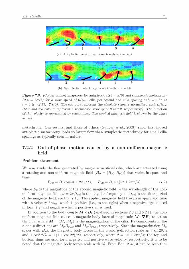
the area swept for symplectic metachrony and enhance it for antiplectic metachrony) andbody couple (which increase the area swept for symplectic metachrony and reduce it forantiplectic metachrony). Clearly, the deviation of the swept area from the synchronouslybeating cilia is governed by the competition between these two effects.
The area swept by the cilia under the influence of both body forces and couples as afunction of L/λM for different cilia spacings is shown in Fig. 7.12. By comparing Fig. 7.11with Fig. 7.12, it can be clearly deduced that the effect of body forces dominated overthe effect of body couples, leading to a larger swept area for AM compared to SM. Asmentioned earlier (see table 7.1), for small wavelengths (λM < 0.15L) the body forcesacting towards the bottom boundary in the case of AM are so high that the area sweptby the cilia diminishes and in some cases the cilia do not beat at all.
Analysis of fluid flow
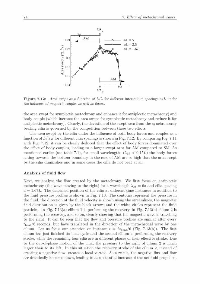
Next, we analyse the flow created by the metachrony. We first focus on antiplecticmetachrony (the wave moving to the right) for a wavelength λM = 6a and cilia spacinga = 1.67L. The deformed position of the cilia at different time instances in addition tothe fluid pressure profiles is shown in Fig. 7.13. The contours represent the pressure inthe fluid, the direction of the fluid velocity is shown using the streamlines, the magneticfield distribution is given by the black arrows and the white circles represent the fluidparticles. In Fig. 7.13(a) cilium 1 is performing the recovery, in Fig. 7.13(b) cilium 2 isperforming the recovery, and so on, clearly showing that the magnetic wave is travellingto the right. It can be seen that the flow and pressure profiles are similar after everytbeat/6 seconds, but have translated in the direction of the metachronal wave by onecilium. Let us focus our attention on instance t = 2tbeat/6 (Fig. 7.13(b)). The firstcilium has just finished its beat cycle and the second cilium is performing the recoverystroke, while the remaining four cilia are in different phases of their effective stroke. Dueto the out-of-phase motion of the cilia, the pressure to the right of cilium 2 is muchlarger than to its left. In this situation the recovery stroke of the cilium 2, instead ofcreating a negative flow, creates a local vortex. As a result, the negative flux and floware drastically knocked down, leading to a substantial increase of the net fluid propelled.

7.3. Conclusions 75
Consequently, the created fluid flow is unidirectional. This can also be seen from thevariation of the flux and flow as a function of time (see Fig. 7.13(h)). The six periodicdips in the flux profile are caused by the recovery stroke of the cilia. The negative flux,however, is very small compared to the positive flux, which leads to a nearly monotonousincrease of the fluid flow with time and a much larger fluid flow at the end of a cycle (0.6in units of πL2/2) compared to the synchronously moving cilia (0.2 in units of πL2/2,see Fig. 5.4).
The flow (normalised by πL2/2) and effectiveness are plotted as a function of L/λM
for different cilia spacings in Fig. 7.14. For a given cilia spacing, the flow nicely correlateswith the area swept by the free end of the cilia (compare Figs. 7.12 and 7.14(a)). This wasalso observed in our earlier studies (Khaderi et al., 2009, 2010) for the case of uniformlybeating cilia. In the case of symplectic metachrony, as the wavelength gets smallerthe magnetic body forces increase, pushing the cilia away from the bottom boundary,which causes a larger negative flow (see the dashed lines in Fig. 7.14(c) for symplecticmetachrony), and a resulting decrease in the net fluid transported and effectiveness. Atsmall wavelengths (λM < 4L) of antiplectic metachrony, the magnetic body forces actingduring the beginning of the effective stroke are large and do not allow the cilia to exhibita complete effective stroke. Now, the positive flow is low (see the solid lines in Fig. 7.14(c)for antiplectic metachrony), causing the net fluid transported and effectiveness to attainlow values.
In most of the cases, the flow caused by the metachronal motion of the cilia is largerthan that of the synchronously beating cilia, even though the area swept in the lattercase is larger. This, as seen earlier, is because of the reduction in the negative flowcaused by the recovery-induced vortex formation (see also (Khaderi et al., 2011b)). Infact, as shown in Fig. 7.14(c), the positive flow is also reduced. However, the reductionin the negative flow is more than the reduction in the positive flow. Consequently, theeffectiveness of fluid propulsion is also higher compared to synchronously beating cilia(see Fig. 7.14(b)). When the cilia spacing is decreased the viscous resistance per ciliumdecreases, which causes the normalised flow to increase. However, decreasing the ciliaspacing below 2.5L does not increase the fluid propelled for symplectic metachrony. Inthese cases, the cilia are close together during their effective stroke, which leads to anobstruction of the positive flow of a cilium by its neighbours (Khaderi et al., 2011b).It can thus be seen that in the presence of non-uniform magnetic fields we obtain asignificant enhancement in the fluid flow for the case of antiplectic metachrony. Howeverin the case of symplectic metachrony, the increase in the flow is only limited.
7.3 Conclusions
We have studied the flow created by a two-dimensional array of artificial cilia as a functionof the phase lag and spacing between neighbouring cilia. Two methods of generating ametachronal wave are considered; by prescribing a phase difference between adjacent ciliaand by using a non-uniform magnetic field. In the latter case, the magnetic body forcesacting on the cilia lead to a reduction of the asymmetric area for the case of symplecticmetachrony compared to antiplectic metachrony. The flow per cycle and the effectiveness(which is a measure of the unidirectionality of flow) are considerably enhanced when thecilia start beating out-of-phase, as compared to synchronously beating cilia. While theamount of flow enhancement depends on the inter-cilia spacing, the effectiveness is not

76 7. Effect of metachronal waves
1 2 3 4 5 6
(a) t = tbeat/6
(b) t = 2tbeat/6
(c) t = 3tbeat/6
(d) t = 4tbeat/6
(e) t = 5tbeat/6
(f) t = tbeat
-20 -16 -12 -8 -4 0 4 8 12 16 20
ptbeat/µ
t/tbeat
Flu
x/(π
L2 /2
t beat)
Flo
w/(π
L2 /2
)
0 0.5 1
0
0.5
1
1.5
2
0
0.2
0.4
0.6
0.8
FlowFlux
(a) (b) (c) (d) (e) (f)
(h)
Figure 7.13: (a) - (f) Contours of pressure normalised with µ/tbeat at different time instances.
The direction of the fluid flow is represented by the streamlines, the magnetic field distribution
is shown using the black arrows and the white circles represent fluid particles. (h) Flow and
flux as a function of time, with the instances corresponding to (a) - (f) duly marked.
significantly influenced. Metachrony is observed to completely knock-down the negativeflow to zero due to the vortex formation caused by the shielding of the recovery stroke.Interestingly, we find that the enhancement is achieved even for small phase differencesand large wavelengths. In the case of metachronal waves obtained by prescribing aphase difference, the direction of travel of the metachronal wave is not important forlarge cilia spacings. In all other cases, the fluid flow is larger for antiplectic metachrony

7.3. Conclusions 77
L/λM
L/λΜ
Flo
wpe
rcy
cle/
(πL2 /2
)
-0.4 -0.2 0 0.2 0.4
-0.4-0.200.20.4
0
0.1
0.2
0.3
0.4
0.5
a/L = 5a/L = 2.5a/L = 1.67
SM
AM
(a)
L/λM
L/λM
Effe
ctiv
enes
s
-0.4 -0.2 0 0.2 0.4
-0.4-0.200.20.4
0
0.2
0.4
0.6
0.8
1
1.2 SM
AM
(b)
L/λM
L/λΜ
Flo
w/(π
L2 /2
)
-0.4 -0.2 0 0.2 0.4
-0.4-0.200.20.4
0
0.2
0.4
0.6
0.8
SM
AM
Positive flow
Negative flow
(c)
Figure 7.14: Flow and effectiveness as a function of a/λ for different inter-cilium spacings a/L.
AM and SM refer to antiplectic metachrony (the wave direction is opposite to the direction of
the effective stroke) and symplectic metachrony (the wave direction and the effective stroke
direction are the same), respectively. The area flow is significantly enhanced for an antiplectic
metachrony compared to symplectic metachrony.
compared to symplectic metachrony, which is related to the obstruction of the positiveflow for symplectic metachrony. It is therefore beneficial if the magnetic actuation of theartificial cilia is designed such that it results in an antiplectic metachrony. Our resultssuggest that an antiplectic metachrony is adopted by the cilia on paramecia and in therespiratory system to maximize the fluid propelled. However, ciliary systems (such ason Opalina) that exhibit symplectic metachrony are also present in nature. It will beof interest to investigate what property is optimised by symplectic metachrony in thesesystems.

78 7. Effect of metachronal waves
Mx
Bx,x
By,x
fx
fy
Symplectic metachrony Antiplectic metachrony Mx
Bx,x
By,x
fx
fy
+–+
–+
(a) Time t = 0 (b) Time t = 0 +– –
––
+–+
–+
(c) t = 2 ms (d) t = 2 ms ++–
+–
– ––
++
(e) t = 7 ms (f) t = 4 ms –++
––
– 0–
0+
(g) t = 9 ms (h) t = 7.5 ms – 0+
0–
Table 7.1: Motion of a super-paramagnetic cilium under the influence of a non-uniform rotating
magnetic field that travels in space to the left (symplectic metachrony) and right (antiplectic
metachrony). The thick arrows, hollow arrow heads and thin arrows represent the applied
magnetic field, magnetization and magnetic body forces, respectively. The direction of the
magnetization (Mx), field gradients (Bx,x and By,x) and body forces (fx and fy) at different
instants are also shown using the + and - symbols.