university of groningen a comparison of nonlocal continuum ... ·...
TRANSCRIPT

University of Groningen
A comparison of nonlocal continuum and discrete dislocation plasticity predictionsBittencourt, E.; Needleman, A.; Gurtin, M.E.; van der Giessen, Erik
Published in:Journal of the Mechanics and Physics of Solids
DOI:10.1016/S0022-5096(02)00081-9
IMPORTANT NOTE: You are advised to consult the publisher's version (publisher's PDF) if you wish to cite fromit. Please check the document version below.
Document VersionPublisher's PDF, also known as Version of record
Publication date:2003
Link to publication in University of Groningen/UMCG research database
Citation for published version (APA):Bittencourt, E., Needleman, A., Gurtin, M. E., & Giessen, E. V. D. (2003). A comparison of nonlocalcontinuum and discrete dislocation plasticity predictions. Journal of the Mechanics and Physics of Solids,51(2), 281 - 310. [PII S0022-5096(02)00081-9]. DOI: 10.1016/S0022-5096(02)00081-9
CopyrightOther than for strictly personal use, it is not permitted to download or to forward/distribute the text or part of it without the consent of theauthor(s) and/or copyright holder(s), unless the work is under an open content license (like Creative Commons).
Take-down policyIf you believe that this document breaches copyright please contact us providing details, and we will remove access to the work immediatelyand investigate your claim.
Downloaded from the University of Groningen/UMCG research database (Pure): http://www.rug.nl/research/portal. For technical reasons thenumber of authors shown on this cover page is limited to 10 maximum.
Download date: 10-02-2018

Journal of the Mechanics and Physics of Solids51 (2003) 281–310
www.elsevier.com/locate/jmps
A comparison of nonlocal continuum and discretedislocation plasticity predictions
E. Bittencourta, A. Needlemana ;∗, M.E. Gurtinb,E. Van der Giessenc
aDivision of Engineering, Brown University, Providence, RI 02912, USAbDepartment of Mathematics, Carnegie Mellon University, Pittsburgh, PA 15213, USA
cDepartment of Applied Physics, University of Groningen, Nyenborgh 4, 9747 AG Groningen,The Netherlands
Received 29 January 2002; received in revised form 19 July 2002; accepted 30 July 2002
Abstract
Discrete dislocation simulations of two boundary value problems are used as numerical exper-iments to explore the extent to which the nonlocal crystal plasticity theory of Gurtin (J. Mech.Phys. Solids 50 (2002) 5) can reproduce their predictions. In one problem simple shear of aconstrained strip is analyzed, while the other problem concerns a two-dimensional model com-posite with elastic reinforcements in a crystalline matrix subject to macroscopic shear. In theconstrained layer problem, boundary layers develop that give rise to size e5ects. In the com-posite problem, the discrete dislocation solutions exhibit composite hardening that depends onthe reinforcement morphology, a size dependence of the overall stress–strain response for somemorphologies, and a strong Bauschinger e5ect on unloading. In neither problem are the quali-tative features of the discrete dislocation results represented by conventional continuum crystalplasticity. The nonlocal plasticity calculations here reproduce the behavior seen in the discretedislocation simulations in remarkable detail.? 2003 Elsevier Science Ltd. All rights reserved.
Keywords: Constitutive behavior; Crystal plasticity; Dislocations; Metallic materials
1. Introduction
Classical plasticity theories predict a size independent response, while a consider-able body of experimental evidence, e.g. Ebeling and Ashby (1966), Brown and Ham
∗ Corresponding author. Tel.: +1-401-863-2863; fax: +1-401-863-1157.E-mail address: [email protected] (A. Needleman).
0022-5096/03/$ - see front matter ? 2003 Elsevier Science Ltd. All rights reserved.PII: S0022 -5096(02)00081 -9

282 E. Bittencourt et al. / J. Mech. Phys. Solids 51 (2003) 281–310
(1971), De Guzman et al. (1993), Fleck et al. (1994), Ma and Clarke (1995) andStDolken and Evans (1998), has accumulated that inhomogeneous plastic Eow in crys-talline solids is inherently size dependent over a scale that ranges from a fraction of amicron to a hundred microns or so—with smaller generally being harder. There is anintimate connection between size e5ects and gradients of plastic deformation, as wasrecognized by Nye (1953). This connection is through the concept of geometricallynecessary dislocations (Nye, 1953; Ashby, 1970), which is, in essence, a measure ofdensity of net Burgers vector.Predicting a size e5ect has provided the motivation for much work on developing
phenomenological nonlocal theories of plastic Eow. There are a variety of dislocationmechanisms that give rise to scale e5ects, see e.g. Mughrabi (1983), Aifantis (1984),Ortiz et al. (2000), Busso et al. (2000). The focus here is on phenomenological modelsthat incorporate a length scale aimed at modeling the nonlocal e5ects arising fromgeometrically necessary dislocations, as, for example, in Fleck and Hutchinson (1993,1997, 2001), Acharya and Bassani (2000), Shu and Fleck (1999), Gao et al. (1999),Huang et al. (2000), Gurtin (2000, 2002) and Svendsen (2002). Length scale e5ectsare incorporated in various ways, in the Eow strength, in the hardening or in thefree energy, and this has a profound e5ect on the boundary value problem structurethat emerges. Although the applicability of these approaches is ultimately decided bycomparing their predictions with experiment, comparisons with the predictions of adirect dislocation based description of plastic Eow can be more detailed and useful inassessing the validity of the various nonlocal formulations.In this regard, it bears emphasis that although much of the focus on geometrically
necessary dislocations has been related to size e5ects, another consequence of the pres-ence of geometrically necessary dislocations is a possible long range stress Held whicha5ects hardening and the Bauschinger e5ect on unloading. In this paper, we compare thepredictions of the nonlocal crystal plasticity theory proposed by Gurtin (2002) with thebehavior obtained from a discrete dislocation description of plastic Eow. Two boundaryvalue problems for a single crystal are considered: simple shear of a constrained layer(Shu et al., 2001) and a model composite material subject to simple shear (Cleveringaet al., 1997, 1998, 1999a). The constrained layer problem is such that a local plasticitytheory would predict uniform shear strain in the layer. Discrete dislocation plasticitygives rise to very di5erent behavior in the constrained layer problem depending onwhether the crystal is oriented for single slip or symmetric double slip. In single slip,the shear sti5ness in the plastic range is of the order of the elastic shear modulus whilein symmetric double slip the e5ective shear sti5ness has a much smaller value, of theorder of the Eow strength. In both single and double slip, the shear strain in the layeris not uniform, but the boundary layers that develop in double slip are much morepronounced than those that develop in single slip and evolve with increasing defor-mation. The aggregate stress–strain response predicted by discrete dislocation plasticitydepends sensitively on the reinforcement morphology. Furthermore, a size dependenceand a large Bauschinger e5ect are seen for one reinforcement morphology but not foranother.We begin by outlining the nonlocal plasticity theory proposed in Gurtin (2002),
restricted to inHnitesmal deformations and rate independent material behavior. Two
E. Bittencourt et al. / J. Mech. Phys. Solids 51 (2003) 281–310 283
sources of hardening are accounted for in this theory; dissipative hardening associatedwith an increase in slip resistance and energetic hardening associated with an increasein free energy due to a density of geometrically necessary dislocations. The discretiza-tion of the nonlocal theory within a Hnite element framework and the implicit timeintegration procedure are then described. Although the theoretical framework and nu-merical implementation are, in principle, fully three dimensional, both the constrainedlayer and the model composite material problems are plane strain problems. Both ide-ally plastic and hardening crystals are considered. An analytical solution is presentedfor a single crystal with two symmetrically oriented slip systems subject to simpleshear. This solution provides a check on the numerical procedure and reveals the cou-pling between dissipative and energetic hardening needed to capture the features seenin the discrete dislocation results.
2. Nonlocal-plasticity: formulation and numerical implementation
2.1. Formulation
The calculations are based on the nonlocal theory of crystal plasticity due to Gurtin(2002) specialized to circumstances where geometry changes are negligible and thematerial response is rate independent. The governing equations are summarized usingCartesian tensor notation.The gradient of the displacement vector, ui, is written as the sum of elastic and
plastic parts
ui; j = ueij + upij : (1)
Attention is conHned to crystalline solids for which plastic deformation takes place bycrystallographic slip on a speciHed set of slip planes. With s(�)i and m(�)i unit vectorsspecifying the slip direction and the slip plane normal, respectively, for slip system �,the plastic part of the displacement gradient is given by
upij =∑�
(�)s(�)i m(�)j (2)
with (�) the total slip on the system �. (We consistently use Greek superscripts, withoutthe summation convention, to label the slip systems.)A motivation for the nonlocal formulation in Gurtin (2002) stems from the fact that
plastic deformation in crystalline solids arises from the motion of dislocations, whichare line defects characterized by a Burgers vector bi. Each dislocation gives rise toa stress Held that, within the context of linear elasticity, falls o5 as 1=r where r isthe distance from the dislocation line. If the dislocations are randomly oriented withBurgers vectors +bi and −bi being equally likely, at distances far from these oppositesigned dislocations, their stress Helds cancel. Hence, if the net Burgers vector in a large(compared with the dislocation spacing) piece of dislocated crystal is zero, there are nolong range stresses associated with the dislocation structure. There is then no increasein free energy associated with the average tractions and displacements on the surface

284 E. Bittencourt et al. / J. Mech. Phys. Solids 51 (2003) 281–310
of this piece of the crystalline solid, although there is a free energy increase that scaleswith length of dislocation line. On the other hand, if the dislocation structure has anet Burgers vector, the tractions on the surface of the piece of dislocated crystal arenot negligible due to the slow 1=r decrease and there is an increase in free energyassociated with the average traction. This increase in free energy scales with the netBurgers vector.The displacement gradient ui; j satisHes the compatibility relation∮
Cui; j dxj = 0; (3)
but neither ueij nor upij do separately. This observation allows one to characterize the net
Burgers vector Bi with respect to a closed loop C in the crystal through the integral
Bi =∮Cupij dxj =
∮S�ij�j dS (4)
in which S is any surface with boundary C and �i is the unit normal Held for Ssuitably oriented with respect to C. The tensor �ij, which is often referred to as Nye’sdislocation density tensor (Nye, 1953) or as the density of geometrically necessarydislocations, is given by the explicit relation
�ij =∑�
ejkl(�); k s(�)i m(�)l ; (5)
where eipq is the alternating tensor. This relation can be rewritten to show that �ijdepends on (�); k at most through derivatives of (�) in the �th slip-plane (Fleck et al.,1994).Because of the nonstandard nature of the theory, the derivation of the balance laws
is based on a principle of virtual work in which Helds �(�) and �(�)i work-conjugate toslips and slip gradients are introduced:∫
B
�ij�ueij +∑
�
�(�)�(�) +∑�
�(�)i �(�); i
dV
=∫9Bq
∑�
q(�)�(�) dA+∫9Bt
ti�ui dA: (6)
Here �ij is the standard stress tensor with �ij = �ji.Using Eqs. (1) and (2), the left-hand side of (6) can be written as∫
B
�ij�ui; j +∑
�
(�(�) − �(�))�(�) +∑�
�(�)i �(�); i
dV;
where
�(�) = m(�)i �ijs(�)j (7)
represents the resolved shear. Since Eq. (6) must hold for variations �u and �(�), weare led to the classical balance
�ij; j = 0 (8)
E. Bittencourt et al. / J. Mech. Phys. Solids 51 (2003) 281–310 285
to a microforce balance
�(�) − �(�) − �(�)i; i = 0 (9)
and to boundary conditions in which either
ti = �ijnj or ui (10)
and either
q(�) = �(�)i ni or (�) (11)
are prescribed at each point of the boundary. Subsequently, a boundary condition ofthe form (�) =0 is referred to as a micro-clamped boundary condition and a boundarycondition of the form q(�) = 0 is termed a micro-free boundary condition.To account for the dependence of the free energy ! on the net Burgers vector, !
is assumed to have the form (Gurtin, 2002)
!("eij ; �ij)
with
"eij =12(u
eij + ueji): (12)
Thermodynamical arguments then lead to the classical relation
�ij =9!9"eij
(13)
in conjunction to the following relation for the “microstress” �(�)i (Gurtin, 2002):
�(�)i = eipqm(�)p Tqrs(�)r (14)
with
Tji =9!9�ij
: (15)
Tji represents a defect stress tensor; note that �ij and Tji are not generally symmetric.Thermodynamics requires also that
∑� �
(�)(�)¿ 0. Consistent with this inequalityand with rate independence we assume that, constitutively,
�(�) = ’(�) sgn (�) (16)
with ’(�)¿ 0, the slip resistance on �, governed by an equation of the form
’(�) =∑&
h(�&)(’(1); ’(2); : : : ; ’(N ); �ij)|(&)| (h(�&)¿ 0): (17)
Here ( ˙) denotes di5erentiation with respect to some monotonically increasing time-likeparameter that characterizes the loading history.Constitutive equation (16) applies only when there is Eow on �, so that (�) �= 0.
We stipulate that the response on � be elastic ((�) = 0) when
|�(�) + �(�)i; i |¡’(�): (18)

286 E. Bittencourt et al. / J. Mech. Phys. Solids 51 (2003) 281–310
In this case �(�) is considered indeterminate, so that the microforce balance (9) issatisHed automatically.The free energy !("eij ; �ij) is taken to have the additive quadratic form
! = 12Lijlk"
eij"ekl +
12‘2�0�ij�ij; (19)
where Lijlk is the elasticity tensor, ‘ is a material length parameter and �0 is a materialstrength parameter. The assumption underlying the uncoupled relation (19) is that theelastic properties are not a5ected by the density of geometrically necessary dislocations.From Eqs. (13) and (15)
�ij = Lijkl"ekl; Tji = ‘2�0�ij (20)
and from Eq. (14)
�(�)i = ‘2�0eipqm(�)p �rqs(�)r : (21)
We now conHne attention to plane strain deformations with respect to the coordinates(x1; x2) under the assumption that s
(�)3 = 0 and m(�)3 = 0 for all slip systems. Granted
this, the two nonvanishing components of �ij are
�i3 =∑�
s(�)i 9(�)(�) (i = 1; 2); (22)
where, for any slip system �, we write 9(�) for the directional derivative with respectto the slip direction s(�)i , e.g.
9(�),= ,;is(�)i ; 9(�)9(&),= ,;ijs
(�)i s(&)j : (23)
From Eqs. (21), (22) and the orthogonality relation s(�)i m(�)i = 0
�(�)i = ‘2�0s(�)i
∑&
S(�&)9(&)(&); (24)
where S(�&) are the slip interaction coePcients
S(�&) = s(�)j s(&)j : (25)
During plastic Eow (9) implies
�(�) = ’(�) sgn (�) − ‘2�0∑&
S(�&)9(�)9(&)(&) (26)
and the stress rate–strain rate relation is
�ij = Lijkl
"kl −∑
�
(�)
2(s(�)k m(�)l + s(�)l m(�)k )
: (27)
Note the presence of two sources of hardening in the yield condition (26): dissipativehardening resulting from the temporal increase in the slip resistance ’(�) via Eq. (17)and energetic hardening represented by the Hnal term in Eq. (26).The slip resistance is taken to have the same initial value for all slip systems; this
initial value is identiHed with the strength parameter �0 in Eq. (20). Two descriptions of

E. Bittencourt et al. / J. Mech. Phys. Solids 51 (2003) 281–310 287
the dissipative hardening are used: (i) to focus on the e5ect of the energetic term inEq. (26), calculations are carried out using h(�&) ≡ 0 in Eq. (17), so that ’(�) ≡ 0 and’(�) ≡ �0; (ii) in other calculations, the e5ect of dissipative hardening is accountedfor by specifying
h(�&) =
{H0; & = �;
.H0; & �= �;(28)
where H0 and . are prescribed constants.The elasticity is taken to be isotropic, characterized by Young’s modulus E and
Poisson’s ratio �, with the shear modulus given by 20=E=(1+ �). Thus, there are sixmaterial parameters that characterize the mechanical behavior: E, �, �0, H0, . (in allcalculations here .=1) and ‘. In addition, for each crystal the number of slip systemsand the orientation of each as speciHed by s(�)i (s(�)i m(�)i = 0) need to be given.
2.2. Numerical implementation
2.2.1. Spatial discretizationThe Hnite element method is based on independent discretizations of the displacement
Held ui(x1; x2) and the slip Held (�)(x1; x2). In each Hnite element, these Helds arerelated to nodal values according to
(�)(x1; x2) =N∑
K=1
2K (x1; x2)3(�)K ; (29)
ui(x1; x2) =N∑
K=1
2K (x1; x2)UKi ; (30)
where N is the number of nodes per Hnite element, and UKi and 3(�)K are the nodal
values of displacement and slip, respectively. Thus, the number of unknowns per nodeis two plus the number of slip systems. Eight node isoparametric quadratic elementswith serendipity interpolation functions 2K are used for both ui and (�). As a conse-quence, ui and (�) are continuous across element boundaries, but the derivatives ui; jand (�); i are not. Within each element the integrations in Eq. (6) are carried out using3× 3 point Gaussian integration.For a representative Hnite element, we calculate
rKi =∫Be�ij2K
;j dv−∫9Bet
ti2K da; (31)
R(�)K =∫Be[(�(�) − �(�))2K − �(�)i 2K
; i ] dv+∫9Beq
q(�)2K da (32)
with the surface integrals appearing only if one or more sides of the element are on asurface where ti or q(�) is prescribed.Denoting the assembled force vectors from Eqs. (31) and (32) by ri and R(�),
respectively, and noting that ui and (�) can be varied independently, the principle of

288 E. Bittencourt et al. / J. Mech. Phys. Solids 51 (2003) 281–310
virtual work (5) implies
ri · �Ui = 0 (33)
for i = 1; 2 and
R(�) · ��(�) = 0 (34)
for � ranging over the number of active slips.Relation (33) implies ri = 0, while in Eq. (34) ��(�) = 0 unless plastic loading
occurs. Only when plastic loading occurs can ��(�) be nonzero and in that case thecorresponding R(�) vanishes. An issue for the numerical implementation is that Eq.(34) is a discretization of a weak statement of the microforce balance (26) whereasthe yield condition, (18), is a pointwise condition that, in the Hnite element context,is met at individual integration points within an element.In the calculations here, the yield condition is evaluated at each Gauss point within an
element. If the plastic loading condition is not met at a Gauss point, the contribution toEq. (32) from that integration point is taken to be zero. This poses no special diPcultyfor evaluating Eq. (32) but, as discussed subsequently, the method for handling theseintegration points does a5ect the stability and convergence of the iterative procedure.
2.2.2. Iteration procedureAt a given stage of the loading history, we suppose that an equilibrium conHguration
is known. We denote the value of the time-like parameter characterizing the loadinghistory at this known conHguration by t. At this stage, the values of �ij and �(�)i atintegration points within each element and the nodal values Ui and 3(�) satisfy Eqs.(33) and (34). An increment of loading is applied and the equilibrium conHgurationcorresponding to the updated load, for which the value of the time-like parameter ist +Tt, needs to be calculated.A predictor–corrector method is used with the Hrst step based on assuming elastic
response at each integration point. A good initial guess for the predicted nodal dis-placements speeds up convergence. To achieve this, the predicted displacements at thecurrent stage of loading are obtained by linear extrapolation of the displacement his-tory at each node (at nodes where displacement boundary conditions are imposed, thenodal values are required to be the imposed values). The displacement increment isthen given by
TUi = U extrapolatedi − Ui(t) (35)
and the trial stress state, �ij, is obtained from
T�ij = LijklT"kl; �ij = �ij(t) + T�ij; (36)
where T"kl is calculated from Tuk and, initially, the trial value of �(�)i is identiHed
with its previous known value.The yield condition, (18), is then checked at each integration point using the trial
stress state. If
|�(�) + �(�)i; i |¡’(�); (37)

E. Bittencourt et al. / J. Mech. Phys. Solids 51 (2003) 281–310 289
where �(�) is calculated from �ij using Eq. (7), then the material behavior at thatintegration point is elastic, otherwise it is plastic.A tangent matrix, A, is constructed from the derivatives
9ri9Ui
;9ri9��) ;
9R(�)9Ui
;9R(�)
9�(�)
to obtain the set of linear equations for the increments TX = [TUi |T�(�)]A ·TX =−b (38)
with b= [ri | R(�)] where ri and R(�) are assembled from the element contributions inEqs. (31) and (32) using the Held quantities �ij and �(�)i .Expressions for the element tangent matrix are long and not revealing, and are not
presented. A nonzero contribution to Eq. (32) and to the corresponding sti5ness matrixterms occurs only when the response at an integration point is plastic. However, a zerovalue of a sti5ness matrix element can result in spurious modes or divisions by zeroduring the solution procedure. These must be avoided for the iterative procedure toconverge. To accomplish this, the contribution to the sti5ness matrix from 9R(�)K =93(�)is evaluated at each integration point as if the material behavior at that point wereplastic. Then, if the material behavior at the integration point under consideration isactually elastic, these sti5ness matrix terms are multiplied by a factor ", where "�1. Itis important to emphasize that this procedure has no e5ect on the converged solution,since it does not alter the values of ri or R(�) in Eqs. (31) and (32).The solution to Eq. (38) gives values of TUi and T3i at each node which are
di5erences between successive iterations. From these, the values of T"kl and T(�) arecalculated at each integration point (T(�) ≡ 0 at integration points where the materialbehavior is elastic). The values of �ij, �i and, when dissipative hardening is included,�(�), are updated at each integration point of the Hnite element mesh using Eqs. (27)and (24) so that
�ij ← �ij + Lijkl
T"kl −
∑�
T(�)s(�)l m(�)k
; (39)
�(�)i ← �(�)i + ‘2�0s(�)i
∑&
S(�&)9(&)T(&) (40)
and
�(�) ← �(�) +∑&
h(�&)T(&): (41)
If the norm of b, calculated using the updated values of �ij and �(�)i , is less than aspeciHed value, the Held quantities of the trial solution are identiHed with those of theequilibrium state at (t+Tt) and a new increment of loading is applied. Otherwise theiterative procedure is repeated from Eq. (37) with the updated trial values.The algorithm used here is similar to numerical procedures used previously in nonlo-
cal plasticity calculations, see De Borst and MDulhaus (1992) and Liebe and Steinmann

290 E. Bittencourt et al. / J. Mech. Phys. Solids 51 (2003) 281–310
(2001), and di5ers from iterative algorithms in conventional plasticity in several ways:(i) unlike a classical return mapping algorithm, the plastic strain at an integration pointdoes not only depend on variables at that point; (ii) convergence does not guaranteethat the yield condition is satisHed at each integration point, but it is satisHed in theweak sense; and (iii) the displacement and the plastic slip are interpolated separately.
3. Results
Two boundary value problems are analyzed: simple shear of a constrained layerand a two dimensional model composite material subject to simple shear. Each ofthese has been analyzed using discrete dislocation plasticity (Cleveringa et al. (1997,1998, 1999a) for the composite material problem and Shu and Fleck (1999) for theconstrained layer problem). The dislocations are represented as line defects in a linearelastic continuum (see e.g. Nabarro, 1967; Hirth and Lothe, 1968) and the methodof solution for boundary value problems is that in Van der Giessen and Needleman(1995) and Cleveringa et al. (1999b). All dislocations are edge dislocations and thedislocations move only by glide, with the magnitude of the glide velocity taken to beproportional to the Peach–Koehler force. New dislocations are generated by simulatingFrank–Read sources and, in the model composite problem, interactions with obstaclesrepresenting forrest dislocations or small precipitates are considered.The discrete dislocation calculations are carried out in an incremental manner. Each
time step involves three main computational stages: (i) determining the forces on thedislocations, i.e. the Peach–Koehler force; (ii) determining the rate of change of thedislocation structure, which involves the motion of dislocations, the generation of newdislocations and their mutual annihilation; and (iii) determining the stress and strainstate for the current dislocation arrangement.In the constrained layer shearing problem, boundary layers develop and there is a
much larger hardening in single slip than in double slip, Shu et al. (2001). For themodel composite material, the aggregate stress–strain response depends sensitively onwhether or not there is a vein of unreinforced matrix parallel to the shear direction. Ifsuch a vein exists, the aggregate stress–strain response is essentially that of the matrixand there is no size e5ect. On the other hand, when all slip planes are blocked, hard-ening is associated with the density of geometrically necessary dislocations needed toaccommodate rotation of the reinforcement and, furthermore, there is a large Baushingere5ect on unloading due to the internal stresses that develop, Cleveringa et al. (1997,1998, 1999a). Here, the extent to which the nonlocal plasticity theory of Gurtin (2002)reproduces the features seen in these plane strain discrete dislocation calculations is ex-plored.
3.1. Boundary layer in simple shear
Simple shear of a crystalline strip, of height h in the x2-direction, is considered,with shearing along the x1-direction as illustrated in Fig. 1. Plane strain and quasi-staticloading conditions are assumed, and the strip is unbounded in the x1- and x3-directions.
E. Bittencourt et al. / J. Mech. Phys. Solids 51 (2003) 281–310 291
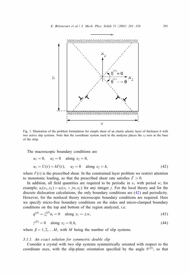
Fig. 1. Illustration of the problem formulation for simple shear of an elastic–plastic layer of thickness h withtwo active slip systems. Note that the coordinate system used in the analyses places the x1-axis at the baseof the strip.
The macroscopic boundary conditions are
u1 = 0; u2 = 0 along x2 = 0;
u1 = U (t) = h3(t); u2 = 0 along x2 = h; (42)
where 3(t) is the prescribed shear. In the constrained layer problem we restrict attentionto monotonic loading, so that the prescribed shear rate satisHes 3¿ 0:In addition, all Held quantities are required to be periodic in x1 with period w; for
example, ui(x1; x2) = ui(x1 + jw; x2) for any integer j. For the local theory and for thediscrete dislocation calculations, the only boundary conditions are (42) and periodicity.However, for the nonlocal theory microscopic boundary conditions are required. Herewe specify micro-free boundary conditions on the sides and micro-clamped boundaryconditions on the top and bottom of the region analyzed, i.e.
q(�) = �(�)i ni = 0 along x1 =±w; (43)
(�) = 0 along x2 = 0; h; (44)
where � = 1; 2; : : : M , with M being the number of slip systems.
3.1.1. An exact solution for symmetric double slipConsider a crystal with two slip systems symmetrically oriented with respect to the
coordinate axes, with the slip-plane orientation speciHed by the angle : (�), so that

292 E. Bittencourt et al. / J. Mech. Phys. Solids 51 (2003) 281–310
(cf. Fig. 1)
: (1) =−: (2) ≡ :: (45)
We consider solutions of this boundary-value problem that have Held quantities inde-pendent of x1. Macroscopic equilibrium requires that �12 be spatially uniform. We seeksolutions for which �11 and �22 vanish.The solution of the elasticity problem is simple shear and the stress is spatially
uniform. Thus the entire strip reaches yield at the same time. At subsequent times,which we discuss here, the entire body undergoes plastic Eow.The orientation of slip system (1) is given by
s(1) = cos :e1 + sin :e2; m(1) =−sin :e1 + cos :e2 (46)
and, for double-slip, system (2) has the analogous equation with : replaced by −:.Recalling that the slip resistances are initially equal (to �0), we have, by symmetry,
(1) = (2) ≡ W; �(1) = �(2) ≡ W�; ’(1) = ’(2) ≡ W’: (47)
We suppose that | W| is monotonically increasing. We may then integrate (17) toarrive at
W’= �0 + 2H0| W|: (48)
The microforce balance (26) then reduces to
d2 Wdx22− ;2 W=−F; (49)
where
;2 =H0
sin4 :�0‘2; F =
W�− �0 sgn W
2 sin4 :�0‘2; (50)
where W¿ 0 for :¡�=4 and W¡ 0 for :¿�=4.Assume Hrst that there is no dissipative hardening (H0 = 0, so that ;=0). Then Eq.
(49) and the boundary conditions (44) yield
W=F2(x2h− x22): (51)
Hence, the slip distribution is quadratic regardless of the value of ‘. The limit ‘→ 0is singular; in this limit the gradient terms in the basic equations disappear and themicroscopic boundary conditions (43) and (44) are meaningless.Consider now the case with dissipative hardening (H0¿ 0). Then, by virtue of the
boundary conditions, the di5erential equation (49) has the solution
W=F;2
[1− cosh ;x2 − (1− cosh ;h) sinh ;x2sinh ;h
](52)
and note thatF;2=W�− �0 sgn W2H0
: (53)

E. Bittencourt et al. / J. Mech. Phys. Solids 51 (2003) 281–310 293
As before, the limit ‘→ 0 is singular; the solution for ‘=0 has W spatially constant.A scaling of the equations with respect to the length scale h shows that the behaviorof solutions as ‘ → 0 is equivalent to their behavior as h → ∞. Thus, to discuss theboundary layer that forms in this limit it is appropriate to consider the semi-inHniteslab 06 x2¡∞ with the boundary conditions for (�) in Eq. (44) replaced by
(�) = 0 along x2 = 0; 9(�)=9x2 → 0 as x2 →∞: (54)
In this case the solution of Eq. (49) is
W=F;2(1− e−;x2 ) (55)
and a measure of the “thickness” of the boundary layer near x2 = 0 is provided by
;−1 = sin2 :√
�0H0
‘: (56)
Thus, both dissipative hardening (as represented by H0) and energetic hardening (asrepresented by ‘) are necessary for the formation of a boundary layer. The absenceof dissipative hardening allows the two boundaries to interact, no matter how far apartthey may be.We now sketch the steps involved in determining the remaining Helds. The only
nonvanishing plastic strain is "p12, which is computed using Eq. (2)
"p12 = k W; k = cos2 :− sin2 := cos 2:: (57)
Similarly, by Eq. (7)
W�= k�12: (58)
Next, using the elastic stress–strain relation (21), assumed isotropic, we Hnd that
�12 = 20("12 − k W): (59)
Averaging this equation with respect to x2 over the interval [0; h] (using a subscript“ave” to denote the average value) we Hnd that, since �12 is spatially constant andsince, by Eq. (42), the average of "12 over the interval [0; h] is 3=2,
�12 = 0(3 − 2k Wave): (60)
In the two cases studied, solutions (51) and (52) of the di5erential equation (49) eachresult in an explicit expression for W as an aPne function of W�, and in each case Wave iseasily computed. Thus eliminating �12 from Eqs. (58) and (60) yields a single (linear)equation to be solved for W�. Knowing W� the equations above can be used to compute�12 and "12, which are the only remaining Helds of interest.Imposing the micro-free boundary condition q(�)=0 on x2=0; h, leads to the condition
that d W=dx2=0 at x2=0; h. The solution to Eq. (49) with H0 �= 0 is then the uniform slipstate W=F=;2 (with H0=0, W is also constant). Hence, the choice of the micro-clampedboundary condition is key for the emergence of the boundary layer.

294 E. Bittencourt et al. / J. Mech. Phys. Solids 51 (2003) 281–310
3.1.2. Numerical solutionsIn the numerical calculations, crystals with one or two slip systems are considered,
as sketched in Fig. 1, with the slip plane orientation speciHed by the angle : (�) =±:.For the nonlocal plasticity theory, Held quantities in the solution to this simple shearingboundary value problem are independent of x1 and macro-equilibrium requires �12 tobe spatially uniform. As shown by the analytical solution, for symmetric double slip�12 is the only nonvanishing in-plane stress component. On the other hand, in singleslip, neither �11 nor �22 vanish.In the discrete dislocation calculations in Shu et al. (2001) Held quantities are not
independent of x1 and the results shown here for the discrete dislocation calculationsare for the cell average shear-stress, �ave12 , and shear-strain, "
ave12 (x2), i.e.
�ave12 =1w
∫ w=2
−w=2�12(x1; h) dx1 (61)
and
"ave12 (x2) =1w
∫ w=2
−w=2"12(x1; x2) dx1: (62)
Note that the average strain "ave12 is a function of x2 while �ave12 is the shear stress thatis work conjugate to 3.In order to facilitate comparison with the discrete dislocation results in Shu et al.
(2001), stress quantities in this Section are normalized by a reference value �ref =50 MPa. The value of the shear modulus is 0= 526�ref , Poisson’s ratio is taken to be� = 0:33 and the Eow strength is speciHed by �0 = 0:309�ref . Various values of thedissipative hardening parameter H0 are used.The overall shear stress versus shear strain response is shown in Fig. 2 for two
calculations for a crystal with a single slip system oriented at : (1) = 60◦ from thex1-axis. In one calculation h=‘ = 1:25 and in the other h=‘ = 125. For comparisonpurposes, the elastic slope, the shear modulus 0, is also shown. The calculations shownin Fig. 2 are carried out with H0 = 0. The plastic shear stress–shear strain response isnearly size independent with an e5ective shear sti5ness of ≈ 0:750. This is in goodagreement with the discrete dislocation calculations of Shu et al. (2001) as well aswith their simple crack model for single slip.The shear strain distributions shown in Fig. 3 for two values of deformation show
the narrow boundary layers that develop in single slip. For the nonlocal theory, forboth single slip and symmetric double slip, since the shear strain distribution for thenonlocal theory is independent of x1"ave12 (x2) = "12(x2). Strain distributions are shownin Fig. 3 for both h=‘ = 1:25 and h=‘ = 125. There is very little size dependenceand very good agreement with the distribution of "ave12 from Shu et al. (2001). Singleslip calculations were also carried out with H0=�ref = 2 and the results do not di5erqualitatively from those shown in Figs. 2 and 3.Overall shear stress–shear strain curves for a symmetrically double slipping crystal
with := 60◦ are shown in Fig. 4 for two values of the characteristic length ‘ and fortwo values of the dissipative hardening parameter H0. Varying h=‘ by a factor of 100shows that a small increase of the overall hardening with decreasing size is predicted

E. Bittencourt et al. / J. Mech. Phys. Solids 51 (2003) 281–310 295
Γ
σ 12ave /τ
ref
0 0.02 0.04 0.06 0.080
5
10
15
20
25
30
35
elastich/l=1.25h/l=125
Fig. 2. Average shear stress response to the imposed shear strain 3 for single slip (: (1) = 60◦) with twovalues of the ratio of layer height h to material characteristic length ‘. Micro-clamped boundary conditions,(1)=0, are imposed at x2=0; h. For comparison purposes, a slope corresponding to the elastic shear modulus0 is also shown.
by the nonlocal theory. The discrete dislocation results in Shu et al. (2001) did notshow a consistent trend for the variation in hardening with size scale. On the otherhand, the discrete dislocation results did give rise to an increasing value of the backextrapolated Eow strength 1 (Shu et al., 2001, Fig. 5) with decreasing size.Fig. 5 shows the shear strain 2"12 =du1=dx2 distribution for crystals with no dissipa-
tive hardening, i.e. H0 = 0. The Hnite element and analytical solutions are coincident.There is nearly no size dependence exhibited by the shear strain distribution. In con-trast, when there is a small amount of dissipative hardening, H0=�ref = 0:02, Fig. 6shows that the strain distribution is strongly size dependent. When the layer thicknessis of the order of the material characteristic length, h=‘=1:25, the strain distribution isnear the quadratic shape of the nonhardening crystal. On the other hand, for h=‘=125,the shear strain is essentially uniform across most of the layer, with boundary layers atthe edges. At the scale in Fig. 6, the numerical and analytical solutions again coincide.The e5ect of dissipative hardening at Hxed size is shown in Fig. 7. Very slight
dissipative hardening has a large e5ect on the predicted strain distribution, with the
1 The back extrapolated Eow strength is obtained by Htting a straight line to the hardening response andextrapolating back to a strain of 0:002.

296 E. Bittencourt et al. / J. Mech. Phys. Solids 51 (2003) 281–310
2ε12
x 2/h
0 0.005 0.01 0.015 0.02 0.0250
0.1
0.2
0.3
0.4
0.5
0.6
0.7
0.8
0.9
1
h/l=125discrete dislocationsh/l=1.25
0.0218Γ =0.0068
Fig. 3. Shear strain proHles at two values of overall shear strain 3 for single slip (: (1) = 60◦) with twovalues of the ratio of layer height h to material characteristic length ‘; (1) = 0 is imposed at x2 = 0; h.Discrete dislocation strain proHles from Shu et al. (2001) are also shown.
strain being nearly uniform over most of the layer for H0=�ref = 2. Calculations of aconstrained shear layer have been carried out (Fleck and Hutchinson, 2001; Niordsonand Hutchinson, 2002) based on the isotropic nonlocal plasticity theory of Fleck andHutchinson (2001) and a strong e5ect of dissipative hardening on the shear straindistribution is also found. 2
Comparison with the discrete dislocation results of Shu et al. (2001) is shown inFigs. 8 and 9. The values H0=�ref = 2 and h=‘ = 3:5 give very good agreement withthe average stress strain response and with the shear strain distributions. The evolutionof the shear strain distribution is in remarkable agreement with that in the discretedislocation calculations. In the calculations, h=1 �m, so that h=‘=3:5 corresponds to‘ = 0:286 �m.
3.2. Model composite material
A planar model composite material consisting of elastic rectangular particles em-bedded in a plastically deforming matrix is subjected to simple shear as sketched in
2 We are indebted to C.F. Niordson of the Technical University of Denmark for discussing unpublishedresults on the shear layer problem with us.

E. Bittencourt et al. / J. Mech. Phys. Solids 51 (2003) 281–310 297
Γ
σ 12ave /τ
ref
0 0.005 0.01 0.015 0.020
0.1
0.2
0.3
0.4
0.5
0.6
0.7
0.8
H0=0H0/τref =0.2
h/l=125
h/l=1.25
Fig. 4. Average shear stress response to the imposed shear strain 3 for double slip (: (1)=60◦, : (2)=−60◦)with two values of the ratio of layer height h to material characteristic length ‘ and two values of the slipsystem dissipative hardening H0, with micro-clamped boundary conditions, (1) = (2) = 0, are imposed atx2 = 0; h.
Fig. 10. The geometrical parameters and the elastic properties of the matrix and of thereinforcement are the same as in Cleveringa et al. (1997, 1998, 1999a). The matrixmaterial has a single slip system with the shearing direction parallel to the slip plane.Two reinforcement morphologies are considered, each having the same area fraction butdi5erent geometric arrangements of the reinforcing phase. In one morphology, termedmaterial (i) in Cleveringa et al. (1997), the particles are square and are separatedby unreinforced veins of matrix material while in the other, termed material (iii) inCleveringa et al. (1997), the particles are rectangular and do not leave any unreinforcedveins of matrix material.The reinforcing particles are arranged in a hexagonal array, with each unit cell being
of width 2w and height 2h (w=h=√3) (see Fig. 10). The particles are of size 2wf×2hf ;
hf =wf =0:416h for material (i) and hf =2wf =0:588h for material (iii). In both cases,the reinforcement area fraction is 0:2.The macroscopic boundary conditions on a unit cell are
u1(t) =±h3(t); u2(t) = 0 along x2 =±h; (63)
where for the composite problem unloading is considered so that 3(t) is not monoton-ically increasing.

298 E. Bittencourt et al. / J. Mech. Phys. Solids 51 (2003) 281–310
2ε12
x 2/h
0 0.01 0.02 0.030
0.1
0.2
0.3
0.4
0.5
0.6
0.7
0.8
0.9
1
numericalanalytical
h/l=1.25 125
Fig. 5. Comparison of numerical and analytical shear strain distributions at 3=0:0218 for an ideally plastic(H0 = 0) crystal with two slip systems (: (1) = 60◦, : (2) = −60◦). Micro-clamped boundary conditions,(1) = (2) = 0, are imposed at x2 = 0; h.
Along the lateral sides (x1 = ±w) periodic macro-scale boundary conditions areimposed and the micro-scale boundary condition is taken to be q(1)(±w)=�(1)i (±w)ni=0. Unless stated otherwise, the calculations are carried out using the micro-clampedboundary condition (1) = 0 on the reinforcement–matrix interface. For comparisonpurposes, some calculations are carried out using the micro-free boundary conditionq(1) = 0 on the reinforcement–matrix interface.Each phase is considered to be elastically isotropic, with shear modulus 0=26:3 GPa
and Poisson’s ratio �=0:33 for the matrix; the corresponding values for the reinforce-ment are 192:3 GPa and 0:17, respectively. A value of �0 =28 MPa for the matrix andh=‘=1:25 was found to give good agreement with the monotonic stress–strain responseobtained from the discrete dislocation calculations. A Hnite element mesh consisting of384 bi-quadratic elements was used.For the composite unit cell in Fig. 10
�ave12 =12w
∫ w
−w�12(x1;±h) dx1: (64)
Overall shear stress versus shear strain curves for material (iii) are shown on Fig.11 for ordinary, local crystal plasticity theory (h=‘ =∞, H0 = 890 MPa) and for thenonlocal theory with h=‘=1:25 and for both H0 = 0 and H0 = 1 MPa. For comparison

E. Bittencourt et al. / J. Mech. Phys. Solids 51 (2003) 281–310 299
2ε12
x 2/h
0 0.01 0.02 0.030
0.1
0.2
0.3
0.4
0.5
0.6
0.7
0.8
0.9
1
numericalanalytical 1.2525h/l=125
Fig. 6. Comparison of numerical and analytical shear strain distributions for double slip (: (1) = 60◦,: (2) =−60◦) with H0=�ref = 0:02 at 3=0:0218 for various values of the ratio of layer height h to materialcharacteristic length ‘. Micro-clamped boundary conditions, (1) = (2) = 0, are imposed at x2 = 0; h.
purposes, the discrete dislocation results from Cleveringa et al. (1997, 1999a) are alsoplotted. A small amount of dissipative hardening, H0 = 1 MPa, gives nearly the samestress–strain behavior as the calculation with H0=0. Additional calculations using valuesof H0 up to 200 MPa, not plotted, showed no signiHcant change in the extent of theBauschinger e5ect from what is seen in Fig. 11. In the calculations, h=1 �m, so thath=‘=1:25 corresponds to ‘=0:8 �m. This gives a very good Ht to the loading curve,but somewhat underestimates the plastic deformation on load reversal. On unloading,both the discrete dislocation and the calculations based on Gurtin’s (2002) nonlocalcrystal plasticity theory exhibit a strong Bauschinger e5ect. The calculation based onlocal crystal plasticity theory, on the other hand, gives essentially an elastic responseon unloading. In addition, unloading calculations carried out here using the nonlocaltheory of Acharya and Bassani (2000) give the same, essentially elastic, unloadingcurve seen in Fig. 11 for the local theory.The e5ect on the overall response of the micro-boundary conditions used at the
matrix–reinforcement interface is shown in Fig. 12 for material (iii). Also shown forboth sets of boundary conditions are results for h=‘=12:5. Although only the ratio h=‘matters, for the purposes of discussion, these will be considered as corresponding to anincrease in physical size h with a Hxed material length. The nonlocal plasticity theorypredictions show that the hardening is reduced for the larger reinforcement, h=‘=12:5,

300 E. Bittencourt et al. / J. Mech. Phys. Solids 51 (2003) 281–310
2ε12
x 2/h
0 0.01 0.02 0.030
0.1
0.2
0.3
0.4
0.5
0.6
0.7
0.8
0.9
1
H0=0H0/τref =0.02H0/τref=0.2H0/τref=2
Fig. 7. Numerically computed shear strain distributions for double slip (: (1) = 60◦, : (2) = −60◦) withh=‘ = 25 at 3 = 0:0218 for various values of the slip system dissipative hardening H0=�ref . Micro-clampedboundary conditions, (1) = (2) = 0, are imposed at x2 = 0; h.
and that there is a considerable reduction in reverse plasticity. When the micro-boundarycondition q(1)=0 is imposed at the interface, as shown in Fig. 12b, the strain hardeningwith h=‘= 1:25, is much less than in Fig. 12a and, when h=‘ is increased to 12.5, thedi5erence from the local solution is small. There is good agreement between the overallstress–strain curves obtained from the discrete dislocation calculations and the nonlocalcalculations with the micro-clamped boundary condition (1)=0 imposed at the particle–matrix interface. This comparison suggests that the appropriate boundary condition atthe particle–matrix interface is the micro-clamped one.Contours of slip, (1), for material (iii) are shown in Fig. 13. The stress levels at
3=0:0096 are �ave12 =0=2:74×10−3 in Figs. 13a and 13b (corresponding to the stages ofdeformation from which unloading occurs in Fig. 11) and �ave12 =0=2:20× 10−3 in Fig.13c (the stage of deformation from which unloading occurs in Fig. 12b). For the localtheory, h=‘ =∞, in Fig. 13a slip is localized near the central reinforcement. On theother hand, for the nonlocal theory with h=‘=1:25, both with the micro-clamped, Fig.13b, and the micro-free, Fig. 13c, boundary conditions slip is more spread out in theunit cell and slip bands away from the central reinforcement are seen, consistent withthe displacement distributions seen in Cleveringa et al. (1997). The slip distribution re-Eects the rotation of the reinforcement (see Cleveringa et al., 1997), which requires the

E. Bittencourt et al. / J. Mech. Phys. Solids 51 (2003) 281–310 301
Γ
σ 12ave /τ
ref
0 0.005 0.01 0.015 0.020
0.1
0.2
0.3
0.4
0.5
0.6
0.7
0.8
0.9
1
1.1
1.2
1.3
1.4
discrete dislocationsH0/τ ref=2; h/l=3.5
Fig. 8. Comparison of the discrete dislocation and nonlocal plasticity average shear stress response to theimposed shear strain 3 for double slip (: (1) = 60◦, : (2) =−60◦). The discrete dislocation data is from Shuet al. (2001).
presence of geometrically necessary dislocations near the reinforcement, Ashby (1970).In Fig. 14a, with the micro-clamped boundary condition, the contours of micro-stress�(1)1 reEect a density of geometrically necessary dislocations at the particle–matrix inter-face as seen in the discrete dislocation distribution for material (iii) in Cleveringa et al.(1997). For the micro-free boundary condition, Fig. 14b, the density of geometricallynecessary dislocations is much lower and peaks away from the interface.The aggregate stress–strain response for material (i) in Fig. 15 is essentially the
same as for the matrix material. Furthermore, the response is neither sensitive to thechoice of nonlocal boundary condition at the particle–matrix interface nor to the valueof the material length scale. In addition, no Bauschinger e5ect is predicted. All thesefeatures are consistent with the discrete dislocation calculations although, as seen inFig. 15 some Bauschinger e5ect does emerge from the discrete dislocation analysis butit is much smaller than for material (iii).Fig. 16 shows slip contours for material (i). In these calculations �0 = 14 MPa in
order to Ht the discrete dislocations results. The deformation is localized in a narrowband because of the vein of unreinforced matrix material (Fig. 16). Rotation of thecentral reinforcement is not required and the overall stress–strain response does notshow any hardening. There are strong slip gradients in the x2-direction, but this gradientis not associated with geometrically necessary dislocations and, hence, does not induce

302 E. Bittencourt et al. / J. Mech. Phys. Solids 51 (2003) 281–310
2ε12
x 2/h
0 0.01 0.02 0.030
0.1
0.2
0.3
0.4
0.5
0.6
0.7
0.8
0.9
1
discrete dislocationsH0/τref =2; h/l=3.5
0.0218Γ =0.0068
Fig. 9. Comparison of the discrete dislocation and nonlocal plasticity shear strain distributions at two valuesof imposed shear strain 3 for double slip (: (1) = 60◦, : (2) = −60◦) and with (1) = (2) = 0 imposed atx2 = 0; h. The discrete dislocation data is from Shu et al. (2001).
Fig. 10. Unit cell of a composite material with a doubly periodic array of elastic particles. All slip planesare parallel to the applied shear direction (x1).

E. Bittencourt et al. / J. Mech. Phys. Solids 51 (2003) 281–310 303
Γ
σ 12av
e /µ×1
03
0 0.0025 0.005 0.0075 0.010
0.5
1
1.5
2
2.5
3
3.5
H0=890 MPa; local theory discrete dislocationsH0=0;h/l=1.25H0=1 MPa; h/l=1.25
Fig. 11. Comparison of the discrete dislocation, local and nonlocal plasticity average shear stress, �ave12 , versusshear strain, 3, curves for material (iii). Unloading from 3 = 0:0096 is also shown. The micro-clampedboundary condition, (1) = 0, is imposed at the particle–matrix interface. The discrete dislocation data isfrom Cleveringa et al. (1999a).
energetic hardening. This illustrates the importance of only incorporating gradientsassociated with the density of geometrically necessary dislocations into the nonlocalconstitutive description.
4. Discussion
The discrete dislocation simulations of Cleveringa et al. (1997, 1998, 1999a) and ofShu et al. (2001) highlight characteristic nonlocal e5ects that are a consequence of thepresence of regions with a nonzero net Burgers vector, i.e. the presence of geometri-cally necessary dislocations. These e5ects include size-dependent stress–strain response,deformation boundary layers, morphology dependent hardening in multi-phase materi-als and internal stresses leading to (or enhancing) a Bauschinger e5ect on unloading.None of these features are exhibited by analyses based on a conventional, local theoryof plasticity. The calculations here show that the nonlocal crystal plasticity theory ofGurtin (2002) captures these e5ects in remarkable detail.The constrained shear layer problem has revealed a strong interaction between dis-
sipative hardening and the predicted boundary layer. For an ideally plastic crystal with

304 E. Bittencourt et al. / J. Mech. Phys. Solids 51 (2003) 281–310
Γ0 0.0025 0.005 0.0075 0.01
0
0.5
1
1.5
2
2.5
3
3.5
Γ
σ 12av
e /µ×1
03σ 1
2ave /µ
×103
0 0.0025 0.005 0.0075 0.010
0.5
1
1.5
2
2.5
3
3.5
local theoryh/l=1.25h/l=12.5
(a)
(b)
Fig. 12. Average shear stress, �ave12 , versus shear strain, 3, curves for material (iii) with H0 = 0 and variousvalues of the ratio h=‘. (a) The micro-clamped boundary condition, (1)=0, is imposed at the particle–matrixinterface. (b) The micro-free boundary condition, q(1) = 0, is imposed at the particle–matrix interface.
two slip systems, a quadratic slip distribution occurs across the constrained layer regard-less of the value of the material length scale. A small amount of dissipative hardeninggives rise to a shear strain distribution that, for a suPciently large value of the layerheight, is nearly uniform except for boundary layers at the edges. The simple inter-pretation of this is that with hardening, the crystal attempts to deform in a uniformmanner (as in a local description); but this uniformity is prevented near the boundariesbecause of the harder boundary layers forming there. The analytical solution shows thescaling of the boundary layer thickness with material properties (56) and reveals thatthe absence of dissipative hardening allows the two boundaries to interact regardless of

E. Bittencourt et al. / J. Mech. Phys. Solids 51 (2003) 281–310 305
2.4E-022.2E-022.1E-021.9E-021.7E-021.5E-021.4E-021.2E-021.0E-028.6E-036.9E-035.1E-033.4E-031.7E-030.0E+00
γ (1)(a)
(b)
(c)
Fig. 13. Contours of slip (1) for morphology (iii) 3 = 0:0096. (a) Local plasticity theory, h=‘ =∞, withH0 = 890 MPa. (b) h=‘ = 1:25 and H0 = 0 with the micro-clamped boundary condition (1) = 0 at theparticle–matrix interface. (c) h=‘ = 1:25 and H0 = 0 with the micro-free boundary condition q(1) = 0 at theparticle–matrix interface.

306 E. Bittencourt et al. / J. Mech. Phys. Solids 51 (2003) 281–310
ξ1(1)
2.7E-032.3E-031.9E-031.5E-031.2E-037.7E-043.9E-040.0E+00
-3.9E-04-7.7E-04-1.2E-03-1.5E-03-1.9E-03-2.3E-03-2.7E-03
ξ1(1)
2.7E-032.3E-031.9E-031.5E-031.2E-037.7E-043.9E-040.0E+00
-3.9E-04-7.7E-04-1.2E-03-1.5E-03-1.9E-03-2.3E-03-2.7E-03
(a)
(b)
Fig. 14. Contours of microstress �(1)1 for morphology (iii) with H0 =0 at 3=0:0096. (a) h=‘=1:25 with themicro-clamped boundary condition (1) =0 at the particle–matrix interface. (b) h=‘=1:25 with the micro-freeboundary condition q(1) = 0 at the particle–matrix interface.
how far apart they are. In addition, the large di5erence in behavior seen in the discretedislocation calculations in Shu et al. (2001) between crystals oriented for single slipand for double slip is reproduced by the nonlocal theory. Furthermore, an appropriatechoice of material parameters gives excellent agreement with the discrete dislocationresults for both the single slip and double slip orientations.It is important to note that the dissipative hardening description in the calculations
here is purely local. The nonlocal e5ects arise solely from a dependence of the freeenergy on the density of geometrically necessary dislocations. This gives an energeticcontribution to hardening in the yield condition (26). Nonlocal e5ects can, of course,be included in the dissipative hardening description. However, for crystals undergoing

E. Bittencourt et al. / J. Mech. Phys. Solids 51 (2003) 281–310 307
Γ
σ 12av
e /µ×1
03
0 0.001 0.002 0.003 0.004 0.005 0.0060
0.2
0.4
0.6
0.8
1
1.2
1.4
1.6
micro-clamped (h/l=1.25)micro-free (h/l=1.25)local theory discrete dislocations
Fig. 15. Average shear stress, �ave12 , versus shear strain, 3, curves for material (i) with both micro-clamped,(1) = 0, and micro-free boundary conditions, q(1) = 0, at the particle–matrix interface. Unloading from3 = 0:0058 is also shown. The discrete dislocation behavior from Cleveringa et al. (1999a) and the localtheory prediction are plotted for comparison purposes.
multislip, it is not at all clear as to how to aportion the e5ects of geometrically neces-sary dislocations among the various slip systems. To the extent that a local dissipativehardening description is adequate, this diPculty is avoided.In the model composite material problem, the nonlocal theory of Gurtin (2002)
exhibits a strong Bauschinger e5ect when the composite morphology is such as torequire the development of a density of geometrically necessary dislocations. The sim-ple theory of Acharya and Bassani (2000) can capture the e5ect of reinforcementmorphology on the aggregate stress–strain response, as shown in Bassani et al. (2001),but not the Bauschinger e5ect on unloading. The reason for this is that the simple the-ory of Acharya and Bassani (2000) assumes that nonlocality a5ects only the dissipativehardening matrix.The results also illustrate the strong e5ect of the choice of higher order boundary
conditions. A particularly attractive feature of the theory presented in Gurtin (2002)is that the higher order boundary conditions are amenable to a physical interpretation.The condition (�) =0 signiHes that the surface is hard in the sense that dislocations donot pass through it. On the other hand, the quantity �(�)i ni represents the microtractionwork-conjugate to � on the bounding surface and the condition that this traction vanish

308 E. Bittencourt et al. / J. Mech. Phys. Solids 51 (2003) 281–310
Fig. 16. Contours of slip (1) for morphology (i) at 3 = 0:0058 for h=‘ = 1:25 with the micro-clampedboundary condition, (1) = 0, at the particle–matrix interface.
is tantamount to the condition that there is no force impeding slip on slip system (�)at the boundary.Finally, it is worth noting that the problems considered here illustrate the importance
of accounting for the discreteness of slip systems at small size scales. An isotropictheory can neither exhibit the dependence on the number of active slip systems seen inthe shear layer problem nor the e5ect of reinforcement morphology in the compositeproblem (because this requires distinguishing the particular gradient of slip associatedwith geometrically necessary dislocations).
5. Conclusions
A Hnite element framework has been developed for solving boundary value problemsusing the nonlocal crystal plasticity theory of Gurtin (2002). The development hasbeen restricted to inHnitesmal deformations and rate independent material response.Two plane strain problems have been solved and the predictions of Gurtin’s (2002)nonlocal theory have been compared with the results of discrete dislocation simulations.
• In the constrained shear layer problem, boundary layers and size e5ects can occurwith uniform properties. Whether or not they emerge in the nonlocal theory dependson the higher order boundary conditions imposed.• Both energetic and dissipative hardening play essential roles in the emergence of aboundary layer and in the size e5ect, as explicitly exhibited by the analytical solutionof the nonlocal theory for symmetric double slip.

E. Bittencourt et al. / J. Mech. Phys. Solids 51 (2003) 281–310 309
• The behavior seen in the discrete dislocation results for a constrained layer subject tosimple shear is reproduced in detail by the nonlocal theory, including, for example,the boundary layer evolution and the di5erence in behavior between single slip andsymmetric double slip orientations.• The e5ect of reinforcement morphology on the stress–strain response of the modelcomposite material is captured by the nonlocal theory for both loading and unloading.• In the nonlocal plasticity calculations, the e5ect of geometrically necessary dislo-cations (net Burgers vector) enters only in the expression for the free energy; thedescription of the dissipative hardening is local. As a consequence, the problem ofaportioning the measure of geometrically necessary dislocations among the variousslip systems does not arise.
Acknowledgements
We are pleased to acknowledge support from the Materials Research Science andEngineering Center on On Micro-and-Nano-Mechanics of Electronic and StructuralMaterials at Brown University (NSF Grant DMR-0079964). In addition EB thanks theBrazilian Government for support through a CNPq Fellowship and MG acknowledgessupport from the National Science Foundation and the Department of Energy.
References
Acharya, A., Bassani, J.L., 2000. Incompatibility and crystal plasticity. J. Mech. Phys. Solids 48,1565–1595.
Aifantis, E.C., 1984. On the microstructural origin of certain inelastic models. J. Eng. Mater. Technol. 106,326–330.
Ashby, M.F., 1970. The deformation of plastically non-homogeneous materials. Philos. Mag. 21, 399–424.Bassani, J.L., Needleman, A., Van der Giessen, E., 2001. Plastic Eow in a composite: a comparisonof nonlocal continuum and discrete dislocation predictions. Int. J. Solids Struct. 38, 833–853.
Brown, L.M., Ham, R.K., 1971. Dislocation–particle interactions. In: A. Kelly and R.B. Nicholson (eds)Strengthening Methods in Crystals. Elsevier, Amsterdam, pp. 12–135.
Busso, E.P., Meissonnier, F.T., O’Dowd, N.P., 2000. Gradient-dependent deformation of two-phase singlecrystals. J. Mech. Phys. Solids 48, 2333–2361.
Cleveringa, H.H.M., Van der Giessen, E., Needleman, A., 1997. Comparison of discrete dislocation andcontinuum plasticity predictions for a composite material. Acta Mater. 45, 3163–3179.
Cleveringa, H.H.M., Van der Giessen, E., Needleman, A., 1998. Discrete dislocation simulations and sizedependent hardening in single slip. J. Phys. IV, 83–92.
Cleveringa, H.H.M., Van der Giessen, E., Needleman, A., 1999a. A discrete dislocation analysis of residualstresses in a composite material. Philos. Mag. A79, 863–920.
Cleveringa, H.H.M., Van der Giessen, E., Needleman, A., 1999b. A discrete dislocation analysis of bending.Int. J. Plasticity 15, 837–868.
De Borst, R., MDulhaus, H.-B., 1992. Gradient-dependent plasticity: formulation and algorithmic aspects. Int.J. Numer. Methods Eng. 35, 521–539.
De Guzman, M.S., Neubauer, G., Flinn, P., Nix, W.D., 1993. The role of indentation depth on the measuredhardness of materials. Mater. Res. Symp. Proc. 308, 613–618.
Ebeling, R., Ashby, M.F., 1966. Dispersion hardening of copper single crystals. Philos. Mag. 13, 805–834.Fleck, N.A., Hutchinson, J.W., 1993. A phenomenological theory for strain gradient e5ects in plasticity. J.Mech. Phys. Solids 41, 1825–1857.

310 E. Bittencourt et al. / J. Mech. Phys. Solids 51 (2003) 281–310
Fleck, N.A., Hutchinson, J.W., 1997. Strain gradient plasticity. Adv. Appl. Mech. 33, 295–361.Fleck, N.A., Hutchinson, J.W., 2001. A reformulation of strain gradient plasticity. J. Mech. Phys. Solids 49,2245–2271.
Fleck, N.A., Muller, G.M., Ashby, F., Hutchinson, J.W., 1994. Strain gradient plasticity: theory andexperiment. Acta Metall. Mater. 42, 475–487.
Gao, H., Huang, Y., Nix, W.D., Hutchinson, J.W., 1999. Mechanism-based strain gradient plasticity—I.Theory J. Mech. Phys. Solids 47, 1239–1263.
Gurtin, M.E., 2000. On plasticity of crystals: free energy, microforces, plastic strain gradients. J. Mech. Phys.Solids 48, 989–1036.
Gurtin, M.E., 2002. A gradient theory of single-crystal viscoplasticity that accounts for geometricallynecessary dislocations. J. Mech. Phys. Solids 50, 5–32.
Hirth, J.P., Lothe, J., 1968. Theory of Dislocations. McGraw-Hill, New York.Huang, Y., Gao, H., Nix, W.D., Hutchinson, J.W., 2000. Mechanism-based strain gradient plasticity—II.Analysis, J. Mech. Phys. Solids 48, 99–128.
Liebe, T., Steinmann, P., 2001. Theory and numerics of a thermodynamically consistent framework forgeometrically linear gradient plasticity. Int. J. Numer. Methods Eng. 51, 1437–1467.
Ma, Q., Clarke, D.R., 1995. Size dependent hardness of silver single crystals. J. Mater. Res. 10, 853–863.Mughrabi, H., 1983. Dislocation wall and cell structures and long-range internal stresses in deformed metalcrystals. Acta Metall. 31, 1367–1379.
Nabarro, F.R.N., 1967. Theory of Crystal Dislocations. Oxford University Press, Oxford.Niordson, C.F., Hutchinson, J.W., 2002. Non-uniform plastic deformation of micron scale objects. TechnicalReport, Harvard University.
Nye, J.F., 1953. Some geometrical relations in dislocated solids. Acta Metall. 1, 153–162.Ortiz, M., Repetto, E.A., Stainier, L., 2000. A theory of subgrain dislocation structures. J. Mech. Phys. Solids48, 2077–2114.
Shu, J.Y., Fleck, N.A., 1999. Strain gradient crystal plasticity: size-dependent deformation of bicrystals. J.Mech. Phys. Solids 47, 297–324.
Shu, J.Y., Fleck, N.A., Van der Giessen, E., Needleman, A., 2001. Boundary layers in constrained plasticEow: comparison of nonlocal and discrete dislocation plasticity. J. Mech. Phys. Solids 49, 1361–1395.
StDolken, J.S., Evans, A.G., 1998. A microbend test method for measuring the plasticity length scale. ActaMater 46, 5109–5115.
Svendsen, B., 2002. Continuum thermodynamic models for crystal plasticity including the e5ects ofgeometrically-necessary dislocations. J. Mech. Phys. Solids 50, 1297–1329.
Van der Giessen, E., Needleman, A., 1995. Discrete dislocation plasticity: a simple planar model. Modell.Simul. Mat. Sci. Engin. 3, 689–735.