university of bolton engineering, sports & sciences beng ... · university of bolton...
TRANSCRIPT
TW53
UNIVERSITY OF BOLTON
ENGINEERING, SPORTS & SCIENCES
BEng (Hons) CIVIL ENGINEERING
SEMESTER 2 EXAMINATION 2014/2015
ADVANCED STRUCTURAL ANALYSIS & DESIGN
MODULE NO. CIE6001
Date: Friday 29 May 2015
Time: 10.00 – 1.00
INSTRUCTIONS TO CANDIDATES:
There are FOUR questions Answer ALL questions All questions carry equal marks Total 100 marks for the paper. Extracts from EC3 to be used with Question 2 are included with this paper.

Page 2 of 12
Engineering Sports Sciences BEng (Hons) Degree in Civil Engineering Semester 2 Examination 2014/2015 Advanced Structural Analysis & Design Module CIE6001
Question 1.
80 kN
D B
6m
2m 4m
F
2Mp C
2m
3m A
3m E
Mp
Mp 60 kN
Figure Q1
Figure Q1 shows a rigid-jointed frame ABCDEF pinned to a support at A and fixed to a support at F. The plastic moment of members AB and DEF is Mp, and member BCD is 2Mp. There is a vertical point load of 80 kN at C and a horizontal point load of 60 kN at E.
a. Find the values of MP which correspond to the following collapse mechanisms:
i) Plastic hinges at B, C and D. (3 marks) ii) Plastic hinges at D, E and F. (3 marks) iii) Plastic hinges at B, D and F. (4 marks) iv) Plastic hinges at B, E and F. (5 marks)
b. Draw the bending moment diagram for the critical collapse mechanism
showing values at the joints and the point load positions. (7 marks) c. Sketch an extra possible mechanism and explain how you know that it is not
the critical mechanism. (3 marks) (Total 25 marks)
Please turn the page
Page 3 of 12
Engineering Sports Sciences BEng (Hons) Degree in Civil Engineering Semester 2 Examination 2014/2015 Advanced Structural Analysis & Design Module CIE6001
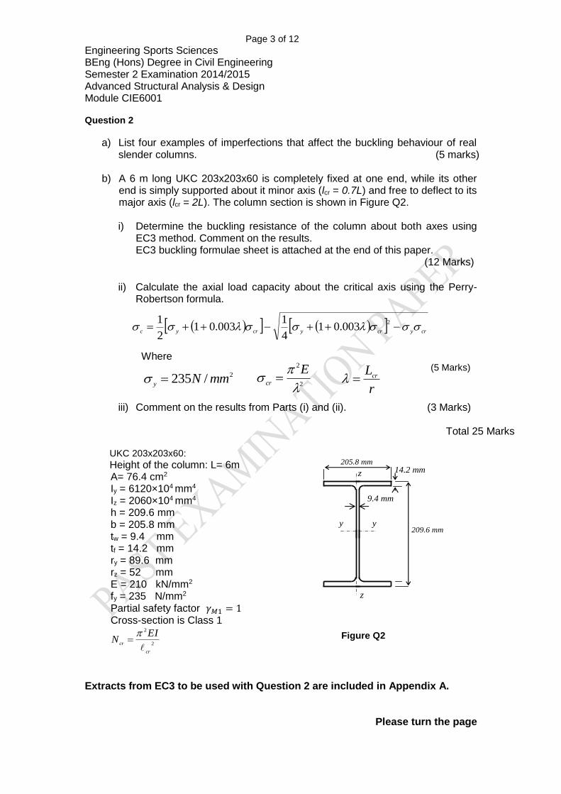
Question 2
a) List four examples of imperfections that affect the buckling behaviour of real slender columns. (5 marks)
b) A 6 m long UKC 203x203x60 is completely fixed at one end, while its other end is simply supported about it minor axis (lcr = 0.7L) and free to deflect to its major axis (lcr = 2L). The column section is shown in Figure Q2.
i) Determine the buckling resistance of the column about both axes using
EC3 method. Comment on the results. EC3 buckling formulae sheet is attached at the end of this paper.
(12 Marks)
ii) Calculate the axial load capacity about the critical axis using the Perry-
Robertson formula.
crycrycryc
2
003.014
1003.01
2
1
Where
(5 Marks)
iii) Comment on the results from Parts (i) and (ii). (3 Marks)
Total 25 Marks
UKC 203x203x60:
Height of the column: L= 6m A= 76.4 cm2 Iy = 6120×104 mm4 Iz = 2060×104 mm4 h = 209.6 mm b = 205.8 mm tw = 9.4 mm tf = 14.2 mm ry = 89.6 mm rz = 52 mm E = 210 kN/mm2 fy = 235 N/mm2
Partial safety factor 𝛾𝑀1 = 1 Cross-section is Class 1
2
2
cr
cr
EIN
Figure Q2
Extracts from EC3 to be used with Question 2 are included in Appendix A.
Please turn the page
2
2
Ecr2/235 mmN
y
r
Lcr
y 209.6 mm
205.8 mm
z
y
z
14.2 mm
9.4 mm
Page 4 of 12
Engineering Sports Sciences BEng (Hons) Degree in Civil Engineering Semester 2 Examination 2014/2015 Advanced Structural Analysis & Design Module CIE6001
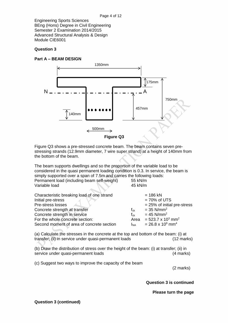
Question 3 Part A – BEAM DESIGN
750mm
457mm
1350mm
N A
175mm
140mm
500mm
Figure Q3
Figure Q3 shows a pre-stressed concrete beam. The beam contains seven pre-stressing strands (12.9mm diameter, 7 wire super strand) at a height of 140mm from the bottom of the beam. The beam supports dwellings and so the proportion of the variable load to be considered in the quasi permanent loading condition is 0.3. In service, the beam is simply supported over a span of 7.5m and carries the following loads: Permanent load (including beam self-weight) 55 kN/m Variable load 45 kN/m Characteristic breaking load of one strand = 186 kN Initial pre-stress = 70% of UTS Pre-stress losses = 25% of initial pre-stress Concrete strength at transfer fck = 35 N/mm2 Concrete strength in service fck = 45 N/mm2 For the whole concrete section: Area = 523.7 x 103 mm2 Second moment of area of concrete section INA = 26.8 x 109 mm4 (a) Calculate the stresses in the concrete at the top and bottom of the beam: (i) at transfer; (ii) in service under quasi-permanent loads (12 marks) (b) Draw the distribution of stress over the height of the beam: (i) at transfer; (ii) in service under quasi-permanent loads (4 marks) (c) Suggest two ways to improve the capacity of the beam (2 marks)
Question 3 is continued
Please turn the page Question 3 (continued)

Page 5 of 12
Engineering Sports Sciences BEng (Hons) Degree in Civil Engineering Semester 2 Examination 2014/2015 Advanced Structural Analysis & Design Module CIE6001
Part B - SLAB DESIGN For a post stressed 285mm deep reinforced concrete flat slab, supported by columns on a square grid of 10m centres, use the load balancing method to choose the profile, number and size of tendons within the slab. Calculate the balanced moment at SLS using an imposed load of 5 kN/m2 and a superimposed dead load of 1.25 kN/m2 applied to the slab. Use the values in the table below for commonly used strand in the UK and assume that the minimum distance from face of concrete to centre line of pre-stressing strand is 65mm. Further assume an initial pre-stress loss of 20% of the characteristic force, 10% loss at transfer and 20% loss at service. Do not calculate the stresses within the slab. Strand type Nominal
tensile strength
(MPa)
Nominal diameter
(mm)
Cross –sectional
area (mm2)
Characteristic value of
maximum force (kN)
Maximum value of
maximum force (kN)
12.9 ‘Super’ 1860 12.9 100 186 213
15.7 ‘Super’ 1770 15.7 150 265 302
15.7 ‘Euro’ 1860 15.7 150 279 319
15.2 ‘Drawn’ 1820 15.2 165 300 342
Draw an indicative sketch section of the slab, showing the output of your calculations. This does not need to be to scale. (7 marks)
(Total 25 marks)
Please turn the page
Page 6 of 12
Engineering Sports Sciences BEng (Hons) Degree in Civil Engineering Semester 2 Examination 2014/2015 Advanced Structural Analysis & Design Module CIE6001
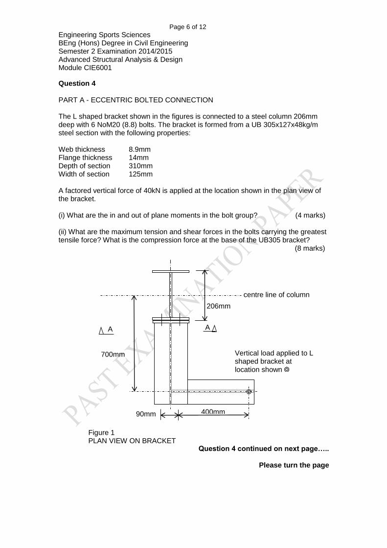
Question 4 PART A - ECCENTRIC BOLTED CONNECTION The L shaped bracket shown in the figures is connected to a steel column 206mm deep with 6 NoM20 (8.8) bolts. The bracket is formed from a UB 305x127x48kg/m steel section with the following properties: Web thickness 8.9mm Flange thickness 14mm Depth of section 310mm Width of section 125mm A factored vertical force of 40kN is applied at the location shown in the plan view of the bracket. (i) What are the in and out of plane moments in the bolt group? (4 marks) (ii) What are the maximum tension and shear forces in the bolts carrying the greatest tensile force? What is the compression force at the base of the UB305 bracket? (8 marks)
Question 4 continued on next page…..
Please turn the page
Vertical load applied to L shaped bracket at location shown
700mm
400mm
A A
90mm
centre line of column
206mm
Figure 1 PLAN VIEW ON BRACKET
Page 7 of 12
Engineering Sports Sciences BEng (Hons) Degree in Civil Engineering Semester 2 Examination 2014/2015 Advanced Structural Analysis & Design Module CIE6001
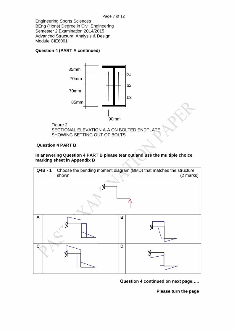
Question 4 (PART A continued)
Question 4 PART B In answering Question 4 PART B please tear out and use the multiple choice marking sheet in Appendix B
Q4B - 1 Choose the bending moment diagram (BMD) that matches the structure shown (2 marks)
A
B
C
D
Question 4 continued on next page…..
Please turn the page
85mm
Figure 2 SECTIONAL ELEVATION A-A ON BOLTED ENDPLATE SHOWING SETTING OUT OF BOLTS
90mm
85mm
70mm
70mm
b3
b2
b1
Page 8 of 12
Engineering Sports Sciences BEng (Hons) Degree in Civil Engineering Semester 2 Examination 2014/2015 Advanced Structural Analysis & Design Module CIE6001
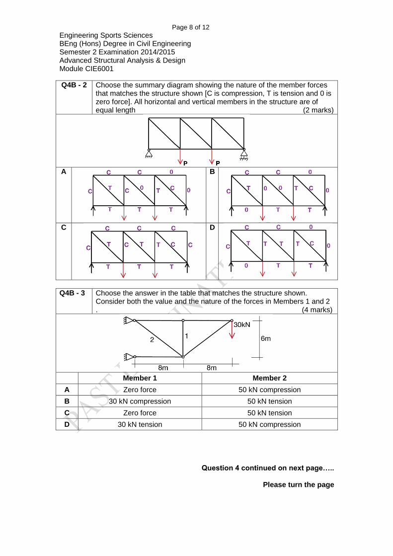
Q4B - 2 Choose the summary diagram showing the nature of the member forces that matches the structure shown [C is compression, T is tension and 0 is zero force]. All horizontal and vertical members in the structure are of equal length (2 marks)
A
B
C
D
Q4B - 3 Choose the answer in the table that matches the structure shown. Consider both the value and the nature of the forces in Members 1 and 2 . (4 marks)
Member 1 Member 2
A Zero force 50 kN compression
B 30 kN compression 50 kN tension
C Zero force 50 kN tension
D 30 kN tension 50 kN compression
Question 4 continued on next page…..
Please turn the page

Page 9 of 12
Engineering Sports Sciences BEng (Hons) Degree in Civil Engineering Semester 2 Examination 2014/2015 Advanced Structural Analysis & Design Module CIE6001
Q4B - 4 Choose the bending moment diagram (BMD) that matches the structure shown (2 marks)
A
B
C
D
Q4B - 5 Choose the bending moment diagram (BMD) that matches the structure shown. Consider the values of the bending moments given in the answer choices (3 marks)
A
B
C
D
(Total 25 marks)
End of Questions Please turn the page

Page 10 of 12
Engineering Sports Sciences BEng (Hons) Degree in Civil Engineering Semester 2 Examination 2014/2015 Advanced Structural Analysis & Design Module CIE6001
APPENDIX A – Extract from EC3 to be used with Question 2
Please turn the page
Page 11 of 12
Engineering Sports Sciences BEng (Hons) Degree in Civil Engineering Semester 2 Examination 2014/2015 Advanced Structural Analysis & Design Module CIE6001
APPENDIX A – Extract from EC3 to be used with Question 2
Please turn the page

Page 12 of 12
Engineering Sports Sciences BEng (Hons) Degree in Civil Engineering Semester 2 Examination 2014/2015 Advanced Structural Analysis & Design Module CIE6001
APPENDIX B Multiple choice answer sheet to be used with Question 4 PART B
Please tear out of the exam paper and enclose with your exam script
Student number:
Questions Circle the correct answers
Marks (please
leave this column blank)
Q4B - 1 A B C D
Q4B - 2 A B C D
Q4B - 3 A B C D
Q4B - 4 A B C D
Q4B - 5 A B C D
TOTAL
It is essential that your answers are clear, as ambiguous answers and crossing out may make it impossible to award marks for parts of this question.
END OF PAPER