university of birmingham catalytic reforming system
TRANSCRIPT

University of Birmingham
Catalytic Reforming System Suitable forTransportation ApplicationsMajewski, Artur; Bossel, Ulf; Steinberger-Wilckens, Robert
DOI:10.1002/fuce.201700135
License:Other (please specify with Rights Statement)
Document VersionPeer reviewed version
Citation for published version (Harvard):Majewski, A, Bossel, U & Steinberger-Wilckens, R 2018, 'Catalytic Reforming System Suitable forTransportation Applications', Fuel Cells. https://doi.org/10.1002/fuce.201700135
Link to publication on Research at Birmingham portal
Publisher Rights Statement:This is the peer reviewed version of the following article: Majewski, A. J., Bossel, U. and SteinbergerWilckens, R. (2018), Catalytic ReformingSystem Suitable for Transportation Applications. Fuel Cells, which has been published in final form at:http://dx.doi.org/10.1002/fuce.201700135. This article may be used for non-commercial purposes in accordance with Wiley Terms andConditions for Use of Self-Archived Versions.
General rightsUnless a licence is specified above, all rights (including copyright and moral rights) in this document are retained by the authors and/or thecopyright holders. The express permission of the copyright holder must be obtained for any use of this material other than for purposespermitted by law.
•Users may freely distribute the URL that is used to identify this publication.•Users may download and/or print one copy of the publication from the University of Birmingham research portal for the purpose of privatestudy or non-commercial research.•User may use extracts from the document in line with the concept of ‘fair dealing’ under the Copyright, Designs and Patents Act 1988 (?)•Users may not further distribute the material nor use it for the purposes of commercial gain.
Where a licence is displayed above, please note the terms and conditions of the licence govern your use of this document.
When citing, please reference the published version.
Take down policyWhile the University of Birmingham exercises care and attention in making items available there are rare occasions when an item has beenuploaded in error or has been deemed to be commercially or otherwise sensitive.
If you believe that this is the case for this document, please contact [email protected] providing details and we will remove access tothe work immediately and investigate.
Download date: 11. Mar. 2022

For Peer Review
Catalytic Reforming System Suitable for Transportation
Applications
Journal: Fuel Cells
Manuscript ID fuce.201700135.R1
Wiley - Manuscript type: Original Research Paper
Date Submitted by the Author: n/a
Complete List of Authors: Majewski, Artur; University of Birmingham, School of Chemical Engineering Bossel, Ulf; ALMUS AG, Steinberger-Wilckens, Robert; University of Birmigham, Chemical Engineering
Keywords: Solid Oxide Fuel Cells (SOFC), Liquefied Natural Gas (LNG), Partial Oxidation, Auxiliary Power Unit (APU), Fuel Cell System
Wiley-VCH
Fuel Cells

For Peer Review
Catalytic Reforming System Suitable for Transportation
Applications
A.J. Majewski1*, U. Bossel
2, R. Steinberger-Wilckens
1
1 School of Chemical Engineering; University of Birmingham, Birmingham, B15 2TT, UK
2ALMUS AG, Morgenacherstrasse 2F, CH-5452, Oberrohrdorf, Switzerland
[*]Corresponding author: [email protected]
Abstract
The paper describes operation and optimization of an onboard reforming system for an
auxiliary power unit solid oxide fuel cell (SOFC APU) system for trucks that use liquid
natural gas as fuel. The reformer system is based on partial oxidation and produces a
reformate gas flow sufficient for a 100 W fuel cell. The ALMUS concept and configuration of
the SOFC APU unit is described. The paper presents analyses of the efficiency of the partial
oxidation reformer. The selected catalyst AB10 is analyzed under various reaction
temperatures and molar ratios of CH4:air. Two reforming reactor configurations are tested;
both with 5 g of the catalyst. The optimal operating conditions for the reactor are proposed.
The reformer is currently operated in an electric furnace that simulates the actual system and
condition in a combustion chamber. The main focus is to obtain stable operation with high
hydrogen yield and low coke deposition. The paper presents analyses of a 1,000 h partial
oxidation stability test. The demonstration of the performance of the CPOX reformer confirms
the system applicability. The observed slow catalyst deactivation is attributed to the detected
coke deposition. The change to the structure of deposited coke along the reactor is explained.
Keywords: Solid Oxide Fuel Cells (SOFC), Liquefied Natural Gas (LNG), Partial Oxidation,
Auxiliary Power Unit (APU), Fuel Cell System.
Page 1 of 45
Wiley-VCH
Fuel Cells
123456789101112131415161718192021222324252627282930313233343536373839404142434445464748495051525354555657585960

For Peer Review
1 Introduction
Hydrogen as a fuel combined with fuel cells offers large potential benefits in reducing
greenhouse gas and other emissions. The cost of hydrogen distribution and the lack of
infrastructure are the main barriers to short-term large-scale implementation of hydrogen-
based technologies. The current solution to this is distributed hydrogen production in small-
scale portable (onboard) and stationary systems. Additional challenges are the fuel cell
durability and reliability [1]
. Economic analyses suggest that In early stages, distributed
hydrogen production will be more cost-effective than a large scale centralized system [2]
.
Distributed reforming technology combined with fuel cells will promote decentralized energy
production. Fuel cells have been undergoing rapid development in the last two decades and
are becoming a practical choice that competes with batteries and combustion engines for
domestic heat and power units, for grid backup power, or portable systems. To achieve long
periods of operation, it is preferred to combine portable fuel cell applications directly with a
reformer. Distributed reforming will deliver hydrogen where it would be needed. Such
systems combine high-energy density of fuel with fuel cell high-power density. Reforming
technologies are already available. However, to promote widespread introduction of
distributed reforming, it is necessary to reduce cost by reducing reaction temperature,
pressure, and materials cost (catalysts). Portable fuel cell applications include auxiliary power
units (APU) (camping, caravans, etc.), light commercial applications (power for emergency,
etc.), portable personal electronics (battery chargers, etc.), and support systems for
transmission towers or telecommunication nodes [1]
.
For solid oxide fuel cells (SOFC), conversion of primary fuel to syngas can be achieved in an
external reformer, directly in the fuel cell, or in indirect internal reforming. Internal reforming
occurs directly on the anode or on the reformer that is separate, but upstream the anode [3]
.
However, to extend the cell life, external reforming of a minimum of 10% of hydrocarbons is
required [4]
. The risk for direct internal reforming is that coke deposition deactivates the
Page 2 of 45
Wiley-VCH
Fuel Cells
123456789101112131415161718192021222324252627282930313233343536373839404142434445464748495051525354555657585960

For Peer Review
anode. An additional problem is temperature gradient formation caused by endothermic
reactions especially with higher hydrocarbons [5]
. An alternative solution for a simple
reforming system is indirect internal reforming. In that system, the reforming catalyst is
located inside the fuel cell [5]
.
The fuel processor in which primary fuel is converted to hydrogen becomes integral to the
fuel cell stack. If the downstream fuel cell is sensitive to CO, additional fuel treatment and
purification is necessary. Usually, hydrogen production consists of several steps including
high temperature reforming on a catalyst followed by gas shift reaction to convert CO to CO2
and at the same time increase H2 output. The next step is the purification that depends on the
H2 application. The growing interest in fuel cell technology has led to the development of a
variety of solutions for small-scale reforming systems and hydrogen production. Most
portable reforming systems combined with fuel cells concentrate on: methanol [6]
, ethanol [7]
,
and on propane [8]
reforming. That is due to the high energy density and because fuel supply is
readily available and widely used for portable applications.
Reforming systems for portable applications require high efficiency, durability and rapid
start-up time [8]
. From available reforming technologies for small scale reforming, steam
reforming, partial oxidation, and autothermal reforming are considered. The reforming system
has to be carefully selected from the available options for the specific application. Catalytic
partial oxidation (CPOX) is less energy efficient than is steam reforming or autothermal
reforming [6]
. However, a heat exchanger is not required by this exothermic process and the
system is more compact. A partial oxidation reactor for portable reformers can be less
expensive than steam reforming [2]
for systems feeding an SOFC. However, the amount of
added N2 can increase the cost of purification for high purity hydrogen applications. The
advantage of partial oxidation is rapid start-up and system simplicity compared to steam
reforming. The disadvantage is the required high-pressure air pump. The start-up procedure
for a CPOX reactor consists of two steps: igniting/preheating and stabilizing time. Many
Page 3 of 45
Wiley-VCH
Fuel Cells
123456789101112131415161718192021222324252627282930313233343536373839404142434445464748495051525354555657585960

For Peer Review
studies have been published about catalysts for partial oxidation of methane [9]
. The reforming
catalyst usually has the structure of a packed bed or a monolith. The main CPOX reaction
produces carbon monoxide and hydrogen Eq. (1) but various other mechanisms are also
possible as detailed in Table 1.
The increasing number of liquefied natural gas (LNG) applications as a fuel for transportation
[10] opens the possibility for an onboard fuel cell application combined with methane
reforming. A major problem for trucks that use LNG is methane emissions related to boil-off
from the LNG tanks. LNG is composed primarily of methane (around 95%), but may also
contain some ethane, propane, nitrogen, and small quantities of higher hydrocarbons [11]
.
The purpose of the present paper is to examine the efficiency of partial oxidation reformers
for a 100 W portable SOFC system. In this work, the performance of the reforming system is
analyzed. The successful completion of this project will increase the potential for application
of portable (or onboard) fuel cell systems and will reduce methane emissions from LNG tanks
by utilization of boil-off gas.
2 Experimental
2.1 APU system
The tested reforming system is designed for a truck cab Auxiliary Power Unit designed by
ALMUS AG [12]
. But it can also be adapted for any small-scale natural gas/CH4 reforming
unit. When the truck engine is shut down, the truck’s battery is fully charged, but will start to
discharge as the cab loads are operated, including lights, TV, computer, fridge, cab-heater fan,
etc. These loads will activate the fuel cell start-up sequence. It will take about 20 minutes to
warm up and will extract about 30 W of battery power to drive the fans and the electronics.
During fuel cell operation, the battery voltage reading will drive the fuel cell output. Before
the electricity generation from the fuel cell starts, some power is required to start the
reforming reaction and to heat-up the fuel cell stack, which comes from the truck battery. The
Page 4 of 45
Wiley-VCH
Fuel Cells
123456789101112131415161718192021222324252627282930313233343536373839404142434445464748495051525354555657585960

For Peer Review
system will primarily use the boil-off LNG from the truck’s tank. While the truck is in
motion, the LNG regasification occurs in a heat exchanger coupled to the engine exhaust.
During parking, if the inherent LNG boil-off in the tank is not sufficient to feed the SOFC
stack, an additional heat exchanger at the stack exhaust can be installed to obtain the required
NG feed. In the proposed system, the fuel processor reaches the required operating
temperature by combusting NG and air on a catalytic combustor. Once the device is hot, the
output from the reformer is fed to the fuel cell. The reforming reaction is self-sustained
without the addition of external fuel to the catalytic combustor. Two air pumps are needed for
the actual system: one for the CPOX reactor and the second for the cathode air. The exhaust
from the reformer is connected to the fuel cell (a planar fuel cell stack with 16 cells). The fuel
cell stack is equipped with an electric heater for the heat-up phase. ALMUS AG has shown
more recently, that special heating arrangements can provide a rapid starting planar stack,
which could be adapted for a truck cab APU, which needs to start in a few minutes [13]
. These
parts (16-cells stack, CPOX reformer, air preheater, air pump, air and fuel supply system, air
and fuel exhaust, valves, etc.) are closely packed, connected by pipes and valves and
surrounded by electric leads, thermocouples etc. to improve temperature distribution and
reduce the size of the APU unit. The SOFC-APU unit requires a DC-DC converter to reach
the 29 V charging level of the truck batteries.
2.2 Reformer
A small-scale reforming system has to be compact, simple and low cost. Partial oxidation was
chosen owing to the simple design and fast start-up, which makes it suitable for portable
power generation systems. A small CPOX reformer measuring 14.5 cm3 capable of producing
enough hydrogen for a 100 W size fuel cell was fabricated by ALMUS AG. On the CPOX
catalyst, NG is converted to hydrogen and carbon monoxide for the anode. The fuel
processing of the methane to produce hydrogen and carbon monoxide for the anode has been
Page 5 of 45
Wiley-VCH
Fuel Cells
123456789101112131415161718192021222324252627282930313233343536373839404142434445464748495051525354555657585960

For Peer Review
proven in many tests. A range of catalysts was tested for partial oxidation of NG under
conditions typical for SOFC operation [5, 14]
. For the experiments presented in this paper, the
AB10 catalyst was selected owing to its high activity and resistance to coke deposition; also
the CO yield was favorable for this catalyst. Characterization of the freshly prepared catalyst
was previously described [5, 14]
. The exact composition of the catalyst and analyses of metal
particles sintering after the reaction cannot be disclosed due to proprietary reasons.
The partial oxidation reforming reaction was carried out in two fixed bed stainless-steel
reactors, each with 5 g of the catalyst: reactor (I) ALMUS AG 20 mm ID (with 6 mm gas
collection tube inside), and a tubular reactor (II) with a bed supported by porous ceramic, 10
mm ID. A tubular reactor with a bed supported by quartz wool was also tested. However, the
pressure in the reactor increased to 1.5 bar caused by the compaction of the wool as observed
after the experiment.
Mass flow controllers controlled the reactant flow rate (CH4, air). The gas composition was
measured by a gas chromatograph after removing water from the reformate gas. The flow rate
of reformate was measured by a wet gas meter. The activity of the catalyst was studied by
temperature programmed reaction with a heating rate of 5oC min
-1 with highest temperature
650, 700 and 750oC under constant CH4:air ratio (1:2.2, 1:2.4, 1:2.6 or 1:2.8) (CH4 724 mL
min-1) and reaction pressure (1 atm). Small-scale portable units usually operate at close to
atmospheric pressure, small stand-alone reformers at a lower pressure of 2-3 atm, compared to
industrial-scale systems that operate at 15-25 atm [2]
.
2.3 Experimental details
The catalyst surface was characterised using a tabletop SEM Hitachi TM3030Plus.
The reactor external temperature was maintained at the constant temperature of 650, 700 or
750oC in a tubular furnace and monitored by thermocouples. The selected temperature range
represented the expected temperature of the afterburner zone of the ALMUS system [13] where
the reforming reactor is located.
Page 6 of 45
Wiley-VCH
Fuel Cells
123456789101112131415161718192021222324252627282930313233343536373839404142434445464748495051525354555657585960

For Peer Review
The gas composition after the CPOX catalyst was analyzed using a mass spectrometer, MKS
Mini-Lab and gas chromatograph (Agilent Technologies 7890A) after cooling using an ice
trap. The gas chromatograph was equipped with seven columns, five valves and three
detectors: a flame ionization detector (FID) and two thermal conductivity detectors (TCD).
The combination of three packed columns (2x HayeSep Q and 1x Molsieve 5A) and two
valves were used for separation of CH4, CO2 and CO; a molecular sieve column was used for
H2 separation.
The coke deposition was analyzed using temperature-dependent mass change profiles (TGA)
by a thermogravimetric analyzer Netzsch 209F1. The heating rate was 10oC min
-1, carried out
between room temperature and 1,000°C. Samples (10-20 mg) of the spent catalyst were
examined by the temperature programmed oxidation (TPO) method in air 50 mL min-1. The
recorded mass reduction was attributed to carbon removal by oxidation.
The test equipment, all connections and gases were chosen to simulate the condition of the
SOFC APU system. The catalytic activity of the catalyst was evaluated by testing in methane
partial oxidation reforming in a continuous flow fixed bed reactor. Before reaction, the
catalyst was purged with nitrogen (1,000 mL min-1) and heated to required temperature with a
rate of 5oC min
-1. Then a gas mixture of CH4 and air was switched into the reactor. The partial
oxidation reforming reaction was carried out at a constant temperature of 650, 700 or 750oC.
Gas flow rates during all experiments were constant (CH4 724 mL min-1) with CH4:air molar
ratio of feed gases, respectively, 1:2.2 1:2.4 1:2.6 or 1:2.8. The experiment was conducted for
24 h (1,000 h for durability test). During the experiment, the exhaust gas composition was
continuously analyzed by the mass spectrometer and by GC in 30 min intervals.
3 Results and Discussion
The tested reformer is presented in Figure 1b. For the final design, the reformer is located
inside a catalytic combustor with an ignition system. The catalyst HiFUEL AB10 from
Page 7 of 45
Wiley-VCH
Fuel Cells
123456789101112131415161718192021222324252627282930313233343536373839404142434445464748495051525354555657585960

For Peer Review
Johnson Matthey was tested for the system. The catalyst was deposited on alumina spheres of
2 mm diameter (Figure 1a). The catalyst (5 g) was located into the fix bed reactor; a stainless
steel container (Figure 1b). The start-up procedure is still under investigation to optimize the
required gas mixture proportions for the rapid start-up. In the actual system, the start-up
procedure consists of two steps. The first is ignition and preheating of the reformer until it
reaches around 450oC (above auto ignition or light-off temperature for the CH4:air mixture
over a Pt/Ru catalyst). The second is preheating of the fuel cell. In the presented report, start-
up was simulated in the electric furnace. AB10 is a noble metal catalyst. Application of such
catalyst makes sense for small-scale portable units where a small amount of catalyst is
needed. The gas hourly space velocity (GHSV) was 30 L h-1
gcat-1 and was lower than for
indirect internal reforming tested in previous work [5]
. According to literature [15]
, methane
conversion is expected to be around 85-95%, at a temperature of 700-750oC, 1 bar, proportion
CH4:air in gas 1:2.4 and GHSV 30 L h-1
gcat-1. Also partial oxidation thermodynamics predict
high methane conversion for those reaction conditions [9a, 9c, 16]
.
Operating conditions of the tested reactor were optimized to generate syngas directly fed to
the 100 W SOFC stack. When oxygen and methane are mixed a range of possible reactions
can occur, which depend on the CH4:air ratio, temperature, pressure and other conditions. A
balance is required to produce the highest possible conversion to H2 without C formation
(coking). The reaction could be a combination of all the reactions listed in Table 1. The
presence of ethane makes the NG partial oxidation more complex than partial oxidation of
pure methane. A range of reactions is possible with ethylene and acetic acid as intermediate or
final products. The goal of the optimization of the reactor design was to improve H2
production and at the same time avoid carbon build-up.
The two reactor configurations (I and II) were tested for the partial oxidation reaction at
identical conditions and with 5 g of the catalyst (Figure 2). Results obtained for the reformer
(II) were similar to results for the reactor (I) developed by ALMUS. Therefore, this
Page 8 of 45
Wiley-VCH
Fuel Cells
123456789101112131415161718192021222324252627282930313233343536373839404142434445464748495051525354555657585960

For Peer Review
configuration was used to test the system at various reaction conditions since the reactor (I)
for ALMUS was welded with no option to change the catalyst. The CH4 conversion was
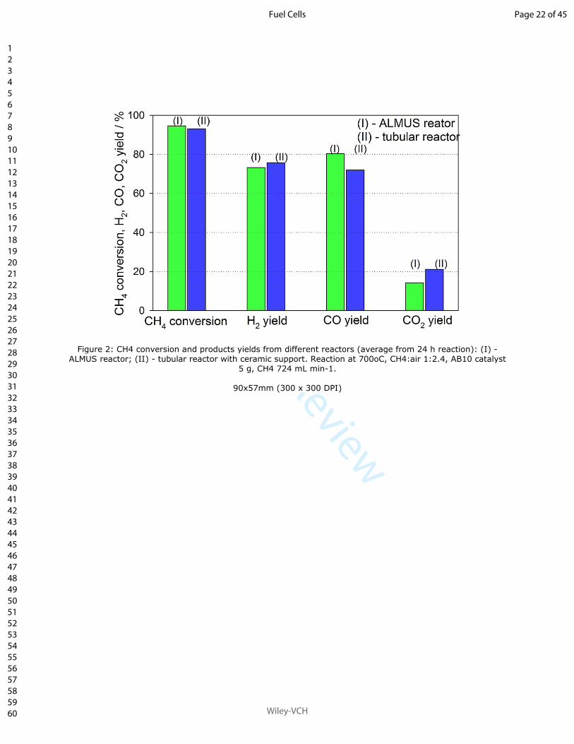
94.6% for the reactor (I) and 93.1% for the reactor (II) (average from 24 h reaction). A small
difference in catalyst selectivity to partial oxidation products was observed. For reactor (I), H2
and CO2 yields were slightly lower but CO yield was improved compared to reactor (II). This
suggests that dry reforming was more efficient in reactor (I). CO was formed with high
selectivity around 80%. H2 selectivity was slightly lower, around 75% (Figure 2). Catalytic
activity for both reactors was stable during up to 24 h on stream. Verlato et al. [17]
observed
that the dry reforming reaction Eq. (5) usually does not occur at a significant rate for noble
metal catalysts under partial oxidation conditions. It is possible that the gas collection tube
located inside the ALMUS reactor improved temperature distribution along the catalyst bed.
The temperature of the catalyst bed was not monitored. However, early results [5]
confirmed
the formation of a hotspot around 5 mm from the reactor inlet with a temperature 50-70oC
above the external reactor temperature.
The AB10 catalyst was tested for partial oxidation of CH4 under various reaction conditions
to optimize reforming. As shown in Figure 3, increasing reaction temperature improved
syngas production and methane conversion. H2 and CO concentration increased with the
increase in reaction temperature. As expected, CH4 conversion increased from 88% at 650oC
to 98% at 750oC. That was caused by the increase in efficiency of steam Eq. (4) and dry Eq.
(5) reforming reactions at the higher reaction temperature. H2 yield increased from 52 to 82%
by increasing the reaction temperature from 650 to 750oC. However, increasing reaction
temperature above 650oC improved CH4 conversion only slightly. The CO yield increased
with reaction temperature from 75% at 650oC to 82% at 750
oC. The results received are
consistent with thermodynamic calculations [9a, 9c, 16]
. The H2 yield increased slightly for a
reaction temperature above 700oC. The fact that CO2 flow increased from 16 to 21% at 700
oC
and decreased to 14% when the temperature reached 750oC was caused by intensified water
Page 9 of 45
Wiley-VCH
Fuel Cells
123456789101112131415161718192021222324252627282930313233343536373839404142434445464748495051525354555657585960

For Peer Review
gas shift reaction (3) and improved dry reforming (5). The high CO concentration at 750oC
resulted from endothermic steam and dry reforming and water gas shift reaction that shifts to
the left side of Eq. (3) at elevated temperature. Early results [5]
suggested that the highest
operation temperature for the AB10 catalyst should be below 800oC. Coke deposition
increased above that temperature caused by CH4 cracking.
Oxygen partial pressure affected the H2 yield (Figure 4). Increasing the air partial pressure
improved CH4 conversion and H2 yield. According to modeling [18]
, for a ratio of CH4:O2
below 1 the primary products of the chemistry are products other than hydrogen, mostly CO,
CO2 and H2O. The molar ratio of CH4:air 1:2.4 is close to the stoichiometric for the partial
oxidation reaction Eq. (1). Increasing or reducing that molar ratio influenced CH4 conversion
Eq. (4). With a ratio of CH4:O2 above stoichiometric Eq. (1), there was not enough oxygen to
convert all methane. For lower CH4:O2 ratios, the active methane conversion region in the
catalyst bed increases in size [18]
. However, increased amount of air mixed with methane
dilutes the fuel and increased GHSV. Also higher oxygen partial pressure results in CO and
H2 combustion. The enhanced effect of the CH4:air ratio could be also explained in terms of
different temperature profiles. The higher amount of oxygen is related to higher temperature
in the oxidation zone and, thus, faster reforming kinetics, despite the lower contact time
(higher GHSV).
In previous work [5]
the same AB10 catalyst was tested for indirect internal reforming for a
100 W tubular SOFC system. However, in such design, there was a limitation to the catalyst
volume (GHSV 120 L h-1
gcat-1). For the external reforming reactor (for planar cells)
presented in this work, it was possible to operate at much lower GHSV of 30 L h-1
gcat-1. Fuel
had much longer contact time with the catalyst than for the system described previously [5]
.
The slower reactions of steam and dry reforming that follow the methane oxidation had
enough time to complete. That increased CH4 conversion, reduced CO2 production, and
Page 10 of 45
Wiley-VCH
Fuel Cells
123456789101112131415161718192021222324252627282930313233343536373839404142434445464748495051525354555657585960

For Peer Review
improved CO and H2 yield. For the CH4:air ratio of 1:2.8 and 750oC, and the methane was
almost completely consumed.
For the tested reactor (fix bed, 5 g AB10 catalyst, CH4 flow 724 mL min-1), of all tested
conditions, CH4:air 1:2.6 at 750oC was optimal for partial oxidation. At the optimum
conditions for CPOX, the catalytic durability of the catalyst was tested. The initial
concentration of CH4, N2 and O2 at the reactor inlet was 27.8, 56.4 and 15.1%, respectively.
The catalytic activity of the AB10 catalyst under steady state conditions was evaluated at
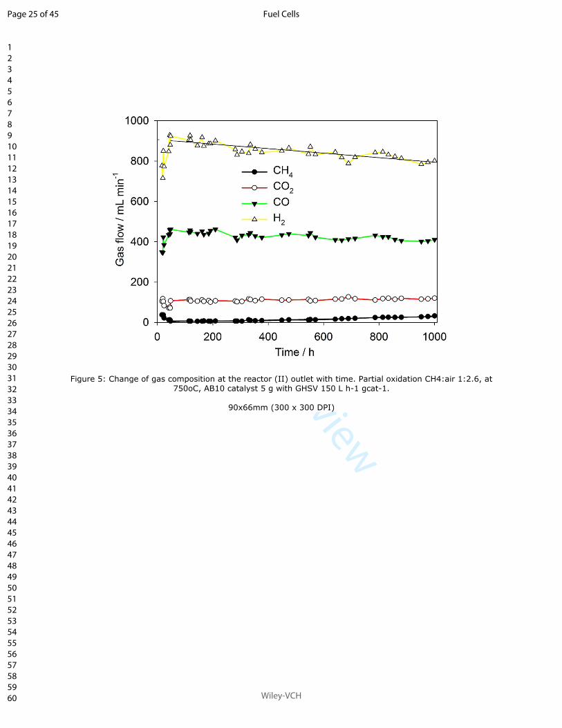
750oC. The profile of the composition of the reformate gas is presented in Figure 5. The
syngas produced was diluted by N2 (and Ar), with around 1.6 L min-1 of N2 at the reactor
exhaust. However, for some systems, dilution by N2 can increase cell performance by
improving the temperature distribution along the cell [5, 14]
. Degradation in hydrogen yield was
around 10% after 1,000 h of partial oxidation under steady state operation, from 900 to 795
mL min-1. CO yield decreased from 450 to 405 mL min
-1 after 1,000 h of reaction. The
production of CO2 slowly increased during the 1,000 h testing. The CH4 concentration at the
reactor exhaust also increased from around 3 to more than 20 mL min-1. The total increase in
CO2 and CH4 flow rate was the same as the decrease in CO flow. The decrease in the
hydrogen flow rate was related to the CO decrease (2.5:1) and to the CO2 and CH4 increase
(also 2.5:1). That was close to the stoichiometry of the steam reforming reaction. This
suggests that steam reforming is the major reaction in the reforming zone of the reactor.
Deactivation of the tested catalyst affected the reforming activity of steam and dry reforming
reactions. The possible reason for deactivation of the noble metal catalyst tested was coke
deposition. However, even after 1,000 h, the CH4 concentration was below 1%, as shown in
Figure 5. CH4 conversion decreased from 99 to 94% after 1,000 h operation (Figure 6). With
this rate of degradation in catalyst activity, the reactor should operate with high efficiency for
a minimum of 5,000 h. No oxygen was observed at the reactor exhaust for all tested cases. In
Page 11 of 45
Wiley-VCH
Fuel Cells
123456789101112131415161718192021222324252627282930313233343536373839404142434445464748495051525354555657585960

For Peer Review
partial oxidation, oxygen is consumed in the first few millimeters of the catalyst bed by
surface reactions [18]
.
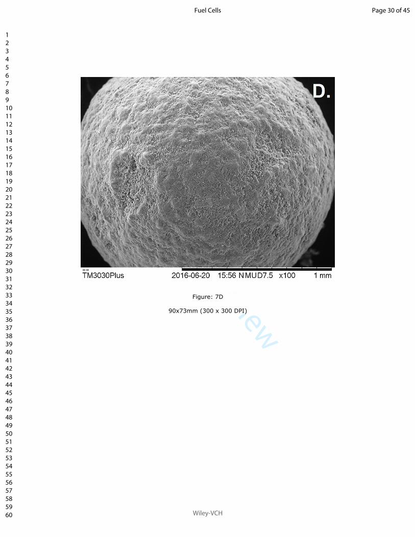
Figure 7 shows SEM images of the AB10 catalyst after the 1,000 h reaction experiment. The
surface of the catalyst particles becomes smoother after 1,000 h caused by sintering, except at
the reactor inlet where particles were covered by coke flakes (Figure 7a-b). Debris of Fe from
oxidation of the stainless-steel reactor were visible on the surface of the catalyst particles after
the reaction, caused by the size of the reactor (10 mm ID). The structure of deposited coke at
the reactor inlet differed from the rest of the reactor. At the inlet, coke had a structure of
flakes (Figure 7b-c) agglomerated in big particles. The catalyst in the middle of the reactor
and at the exhaust was coated with small coke particles equally distributed on the catalyst
surface Figure 7e-f).
The deposited coke is a significant component of catalyst deactivation. Deposited carbon
along the catalyst bed was analyzed by TGA. The coke deposition was much lower than
expected. Early results [5]
for the AB10 catalyst suggested that lack of oxygen leads to coke
formation on the CPOX catalyst. The used CH4:air molar ratio of 1:2.6 presenter in this report
is close to stoichiometric and could result in high coke deposition on the CPOX catalyst.
However, a lower GHSV with higher reaction temperature and a different catalyst form
(spheres) improved resistance to coke deposition. The amount of deposited coke decreased
with the catalyst length (Table 2). The inlet is the most active part of the catalyst bed. Beretta
et al. [19]
reported that 93% of methane can be converted within the first 5 mm from the
catalyst inlet during partial oxidation. Higher coke deposition in the inlet zone was detected
despite the fact that presence of oxygen should prevent this. This might be explained by
different type of deposited coke with the inlet displaying the graphitic type, while the
amorphous type prevailed further downstream the reactor. The characteristic of deposited
coke changed along the catalyst bed. For samples of the catalyst from the reactor inlet, the
change of mass at 680oC was caused by coke oxidation. The high oxidation temperature
Page 12 of 45
Wiley-VCH
Fuel Cells
123456789101112131415161718192021222324252627282930313233343536373839404142434445464748495051525354555657585960

For Peer Review
suggests graphite-like carbon. However, samples from the middle had a change of mass at
100÷150oC caused by moisture removal and a slow steady linear reduction of mass between
300 and 1,000oC. Samples of the catalyst from the reactor outlet (after moisture removal at
100-150oC) had a slow linear change of mass between 300 and 600
oC, after that temperature
the mass was stable. This suggests, that at the bed exhaust soft carbon was deposited
(probably on the metal sites) and mixed graphite and soft coke deposited in the middle of the
reactor. Shamsi et al. [20]
suggested that coke formed on the support is less reactive than coke
deposited on metal sites. This may suggest that oxygen present in the reactant gas mixture at
the catalyst bed inlet oxidizes hydrogen from the deposited coke making it more graphitic.
The slow deactivation of the catalyst with time can be related to the detected coke deposition.
Coke deposition decreased with the catalyst length. The color of the catalyst changed after the
reaction. Fresh catalyst was brown. After 1,000 h of partial oxidation at 750oC, all particles of
the catalyst at the reactor inlet (up to 2 cm from inlet) turned white, and particles in the middle
and at the outlet black.
The catalyst deactivation was caused by coke deposition combined with sintering. During
partial oxidation, there is always a hot-spot formation at the reactor inlet. The hot-spot
formation has been reported [17, 19]
to result in progressive loss of the catalyst activity that
might result in a faster deactivation of the catalyst. Such loss strongly influences the rate of
methane reforming reactions. According to literature [17]
, increase in the particle size of noble
metal is the most probable reason for the decrease in partial oxidation performance during
long time tests. Noble metal sintering affects reforming reactions Eqs. (4) and (5) but has a
lesser effect on oxidation Eqs. (1) and (2) [17]
. The AB10 is a noble metal catalyst and it can
be regenerated by coke oxidation. The procedure for cyclic oxidation to guarantee the long-
term operation is still under investigation. The regeneration temperature and time is limited by
the portable application of the tested system. TPO analyses of the catalyst used suggest that
the regeneration temperature should be above 600oC; however, it should be below system
Page 13 of 45
Wiley-VCH
Fuel Cells
123456789101112131415161718192021222324252627282930313233343536373839404142434445464748495051525354555657585960

For Peer Review
operation temperature. To prevent coke accumulation in long-term operation, Lee et al. [8]
suggested the cyclic operation of several hours of partial oxidation with few minutes of air
oxidation. The cyclic operation can reduce the rate of catalyst deactivation. However, for a
system where reformate is connected directly to an SOFC, that solution is not practical.
The presented results are based on simulation of LNG. In the final system, the low fuel
temperature (down to -160oC) will reduce the catalyst activity at the reformer inlet and will
lead to a smoother temperature profile. Fuel unconverted on the catalyst will be afterward
converted on the anode. That can lead to a cooling effect on the SOFC fuel inlet and is
currently being studied. The investigation of fuel dilution by N2 from partial oxidation is also
still ongoing. The obtained results suggest that the final system control needs a mechanism
that will stop the flow of air in case of problems with fuel supply to prevent anode oxidation.
4 Conclusions
The performance of a small reforming system for a 100 W SOFC system was evaluated. The
catalyst AB10 was analyzed under various reaction temperatures and CH4:air molar ratios.
Although the amount of deposited coke was small, after 1,000 hours of operation the catalyst
slowly deactivated with the decrease in CH4 conversion from 99 to 94% after 1,000 hours of
operation. The demonstrated performance of the CPOX reformer confirmed the potential for
application of the proposed reformer in an auxiliary power system. It is expected, that the
reformer tested in this study will be integrated with a 100 W SOFC system, targeting a market
for auxiliary power systems for LNG-powered trucks.
Acknowledgements
The results are part of the SAFARI project funded under Europe’s Fuel Cell and Hydrogen
Joint Undertaking (FCH JU), Grant Agreement No.325323. The Consortium gratefully
acknowledges the support of the FCH JU.
Page 14 of 45
Wiley-VCH
Fuel Cells
123456789101112131415161718192021222324252627282930313233343536373839404142434445464748495051525354555657585960

For Peer Review
References
[1] T. Wilberforce, A. Alaswad, A. Palumbo, M. Dassisti, A. G. Olabi, Int. J. Hydrogen
Energy 2016, 41, 16509-16522.
[2] J. M. Ogden, can be fund under http://www.afdc.energy.gov/pdfs/31948.pdf, 2002, pp.
1-52.
[3] P. Aguiar, D. Chadwick, L. Kershenbaum, Chem. Eng. Sci. 2002, 57, 1665-1677.
[4] Q. Fang, L. Blum, P. Batfalsky, N. H. Menzler, U. Packbier, D. Stolten, Int. J
Hydrogen Energy 2013, 38, 16344-16353.
[5] A. J. Majewski, A. Dhir, J. Electrochem. Soc. 2016, 163, F272-F277.
[6] H.-S. Wang, K.-Y. Huang, Y.-J. Huang, Y.-C. Su, F.-G. Tseng, Appl. Energy 2015,
138, 21-30.
[7] T. Aicher, J. Full, A. Schaadt, Int. J. Hydrogen Energy 2009, 34, 8006-8015.
[8] S. Lee, G. Keskar, C. Liu, W. R. Schwartz, C. S. McEnally, J.-Y. Kim, L. D. Pfefferle,
G. L. Haller, Appl. Catal. B 2012, 111–112, 157-164.
[9] aA. A.-S. Saleh, Open Catal. J. 2013, 6, 17-28; bQ. Zhu, X. Zhao, Y. Deng, J. Nat.
Gas Chem. 2004, 13, 191-203; cB. C. Enger, R. Lødeng, A. Holmen, Appl. Catal. A:
2008, 346, 1-27.
[10] aE. Stefana, F. Marciano, M. Alberti, J. Loss Prev. Process Ind. 2016, 39, 39-58; bQ.
Tang, J. Fu, J. Liu, F. Zhou, Z. Yuan, Z. Xu, Appl. Therm. Eng. 2016, 103, 1351-1361;
cO. Schinas, M. Butler, Ocean Eng. 2016, 122, 84-96.
[11] E. Graham, A. Kenbar, Flow Meas. Instrum. 2015, 44, 79-88.
[12] ALMUS AG, can be fund under http://www.almus-ag.ch/, 2016.
[13] aU. Bossel, ECS Trans. 2015, 68, 193-199; bU. Bossel, in 12th European SOFC and
SOE forum, Lucerne, 2016.
[14] A. J. Majewski, A. Dhir, ECS Trans. 2015, 68, 2189-2198.
Page 15 of 45
Wiley-VCH
Fuel Cells
123456789101112131415161718192021222324252627282930313233343536373839404142434445464748495051525354555657585960

For Peer Review
[15] aP. D. F. Vernon, M. L. H. Green, A. K. Cheetham, A. T. Ashcroft, Catal. Lett. 1990,
6, 181-186; bV. Dal Santo, C. Mondelli, V. De Grandi, A. Gallo, S. Recchia, L.
Sordelli, R. Psaro, Appl. Catal. A 2008, 346, 126-133.
[16] aS. Kumar, S. Kumar, J. K. Prajapati, Int. J. Hydrogen Energy 2009, 34, 6655-6668;
bJ. E. P. Navalho, I. Frenzel, A. Loukou, J. M. C. Pereira, D. Trimis, J. C. F. Pereira,
Int. J. Hydrogen Energy 2013, 38, 6989-7006.
[17] E. Verlato, S. Barison, S. Cimino, F. Dergal, L. Lisi, G. Mancino, M. Musiani, L.
Vázquez-Gómez, Int. J. Hydrogen Energy 2014, 39, 11473-11485.
[18] A. Raoufi, S. Kapadia, J. C. Newman Iii, Comput. Chem. Eng. 2016, 93, 266-283.
[19] A. Beretta, A. Donazzi, D. Livio, M. Maestri, G. Groppi, E. Tronconi, P. Forzatti,
Catal. Today 2011, 171, 79-83.
[20] A. Shamsi, J. P. Baltrus, J. J. Spivey, Appl. Catal. A 2005, 293, 145-152.
Page 16 of 45
Wiley-VCH
Fuel Cells
123456789101112131415161718192021222324252627282930313233343536373839404142434445464748495051525354555657585960

For Peer Review
Figure Captions
Figure 1: A - catalyst HiFUEL AB10 - pellets. B - External reformer (I) for planar cells
(designed and manufactured by ALMUS AG).
Figure 2: CH4 conversion and products yields from different reactors (average from 24 h
reaction): (I) - ALMUS reactor; (II) - tubular reactor with ceramic support. Reaction at 700oC,
CH4:air 1:2.4, AB10 catalyst 5 g, CH4 724 mL min-1.
Figure 3: Reactor (II) performance at the different reaction temperature (average from 24 h).
CH4:air 1:2.4, 5 g AB10 catalyst, CH4 gas-in flow 724 mL min-1.
Figure 4: Reactor (II) performance for different CH4:air ratio 1:x (average from 24 h).
Reaction temperature 700oC, 5 g AB10 catalyst CH4 if flow 724 mL min
-1.
Figure 5: Change of gas composition at the reactor (II) outlet with time. Partial oxidation
CH4:air 1:2.6, at 750oC, AB10 catalyst 5 g with GHSV 150 L h
-1 gcat
-1.
Figure 6: Change in methane conversion with time. Partial oxidation CH4:air 1:2.6, at 750oC,
AB10 catalyst 5 g with GHSV 150 L h-1
gcat-1, reactor (II).
Figure 7: SEM scans of the AB10 spent catalyst after 1,000 h at 750oC with GHSV 150 L h
-1
gcat-1, CH4:air 1:2.6, reactor (I), A-C reactor inlet, D-F reactor exhaust. C and F - EDX carbon
mapping of scans B and E respectively.
Page 17 of 45
Wiley-VCH
Fuel Cells
123456789101112131415161718192021222324252627282930313233343536373839404142434445464748495051525354555657585960

For Peer Review
Table Captions
Table 1. Overall reactions in the methane partial oxidation system
∆����� Reaction Name
Equation Number
(as referred in manuscript
-36 kJ mol-1 2�� + �� → 2�� + 4�� CH4 partial oxidation (1)
-802 kJ mol-1 �� + 2�� → ��� + 2��� CH4 combustion (2)
-41 kJ mol-1 �� + ��� ↔ ��� + �� water gas shift (3)
+206 kJ mol-1 �� + ��� ↔ �� + 3�� CH4 steam reforming (4)
+247 kJ mol-1 �� + ��� ↔ 2�� + 2�� CH4 dry reforming (5)
-131 kJ mol-1 �� + �� ↔ � + ��� CO hydrogenation (6)
+75 kJ mol-1 �� ↔ � + 2�� CH4 cracking (7)
-173 kJ mol-1 2�� ↔ ��� + � Boudouard (8)
-282 kJ mol-1 2�� + �� → 2��� CO oxidation (9)
-241 kJ mol-1 2�� + �� → 2��� H2 oxidation (10)
Page 18 of 45
Wiley-VCH
Fuel Cells
123456789101112131415161718192021222324252627282930313233343536373839404142434445464748495051525354555657585960

For Peer Review
Table 2. Coke deposition on AB10 catalyst - TGA. Catalyst after 1,000 h at 750oC with
GHSV 150 L h-1
gcat-1, CH4:air 1:2.6
Position in reactor Coke / mg gcat-1
Inlet 14.8
Middle 12.8
Outlet 6.0
Page 19 of 45
Wiley-VCH
Fuel Cells
123456789101112131415161718192021222324252627282930313233343536373839404142434445464748495051525354555657585960

For Peer Review
Figure 1: A - catalyst HiFUEL AB10 - pellets. B - External reformer (I) for planar cells (designed and manufactured by ALMUS AG).
60x39mm (300 x 300 DPI)
Page 20 of 45
Wiley-VCH
Fuel Cells
123456789101112131415161718192021222324252627282930313233343536373839404142434445464748495051525354555657585960

For Peer Review
Figure 1: B
85x39mm (300 x 300 DPI)
Page 21 of 45
Wiley-VCH
Fuel Cells
123456789101112131415161718192021222324252627282930313233343536373839404142434445464748495051525354555657585960
For Peer Review
Figure 2: CH4 conversion and products yields from different reactors (average from 24 h reaction): (I) - ALMUS reactor; (II) - tubular reactor with ceramic support. Reaction at 700oC, CH4:air 1:2.4, AB10 catalyst
5 g, CH4 724 mL min-1.
90x57mm (300 x 300 DPI)
Page 22 of 45
Wiley-VCH
Fuel Cells
123456789101112131415161718192021222324252627282930313233343536373839404142434445464748495051525354555657585960

For Peer Review
Figure 3: Reactor (II) performance at the different reaction temperature (average from 24 h). CH4:air 1:2.4, 5 g AB10 catalyst, CH4 gas-in flow 724 mL min-1.
90x82mm (300 x 300 DPI)
Page 23 of 45
Wiley-VCH
Fuel Cells
123456789101112131415161718192021222324252627282930313233343536373839404142434445464748495051525354555657585960

For Peer Review
Figure 4: Reactor (II) performance for different CH4:air ratio 1:x (average from 24 h). Reaction temperature 700oC, 5 g AB10 catalyst CH4 if flow 724 mL min-1.
90x83mm (300 x 300 DPI)
Page 24 of 45
Wiley-VCH
Fuel Cells
123456789101112131415161718192021222324252627282930313233343536373839404142434445464748495051525354555657585960
For Peer Review
Figure 5: Change of gas composition at the reactor (II) outlet with time. Partial oxidation CH4:air 1:2.6, at 750oC, AB10 catalyst 5 g with GHSV 150 L h-1 gcat-1.
90x66mm (300 x 300 DPI)
Page 25 of 45
Wiley-VCH
Fuel Cells
123456789101112131415161718192021222324252627282930313233343536373839404142434445464748495051525354555657585960

For Peer Review
Figure 6: Change in methane conversion with time. Partial oxidation CH4:air 1:2.6, at 750oC, AB10 catalyst
5 g with GHSV 150 L h-1 gcat-1, reactor (II).
90x65mm (300 x 300 DPI)
Page 26 of 45
Wiley-VCH
Fuel Cells
123456789101112131415161718192021222324252627282930313233343536373839404142434445464748495051525354555657585960

For Peer Review
Figure 7: SEM scans of the AB10 spent catalyst after 1,000 h at 750oC with GHSV 150 L h-1 gcat-1, CH4:air 1:2.6, reactor (I), A-C reactor inlet, D-F reactor exhaust. C and F - EDX carbon mapping of scans B and E
respectively.
90x73mm (300 x 300 DPI)
Page 27 of 45
Wiley-VCH
Fuel Cells
123456789101112131415161718192021222324252627282930313233343536373839404142434445464748495051525354555657585960

For Peer Review
Figure 7: B
90x73mm (300 x 300 DPI)
Page 28 of 45
Wiley-VCH
Fuel Cells
123456789101112131415161718192021222324252627282930313233343536373839404142434445464748495051525354555657585960

For Peer Review
Figure: 7C
90x67mm (300 x 300 DPI)
Page 29 of 45
Wiley-VCH
Fuel Cells
123456789101112131415161718192021222324252627282930313233343536373839404142434445464748495051525354555657585960
For Peer Review
Figure: 7D
90x73mm (300 x 300 DPI)
Page 30 of 45
Wiley-VCH
Fuel Cells
123456789101112131415161718192021222324252627282930313233343536373839404142434445464748495051525354555657585960

For Peer Review
Figure: 7E
90x73mm (300 x 300 DPI)
Page 31 of 45
Wiley-VCH
Fuel Cells
123456789101112131415161718192021222324252627282930313233343536373839404142434445464748495051525354555657585960

For Peer Review
Figure: 7F
90x67mm (300 x 300 DPI)
Page 32 of 45
Wiley-VCH
Fuel Cells
123456789101112131415161718192021222324252627282930313233343536373839404142434445464748495051525354555657585960

For Peer Review
Catalytic Reforming System Suitable for Transportation Applications
A.J. Majewski1*, U. Bossel
2, R. Steinberger-Wilckens
1
1 School of Chemical Engineering; University of Birmingham, Birmingham, B15 2TT, UK,
2ALMUS AG, Morgenacherstrasse 2F, CH-5452, Oberrohrdorf, Switzerland
*Corresponding author: [email protected]
Abstract
The paper describes operation and optimization of an onboard reforming system for an auxiliary
power unit solid oxide fuel cell (SOFC APU) system for trucks that use liquid natural gas as fuel. The
reformer system is based on partial oxidation and produces a reformate gas flow sufficient for a 100
W fuel cell. The ALMUS concept and configuration of the SOFC APU unit is described. The paper
presents analyses of the efficiency of the partial oxidation reformer. The selected catalyst AB10 is
analyzed under various reaction temperatures and molar ratios of CH4:air. Two reforming reactor
configurations are tested; both with 5 g of the catalyst. The optimal operating conditions for the
reactor are proposed. The reformer is currently operated in an electric furnace that simulates the
actual system and condition in a combustion chamber. The main focus is to obtain stable operation
with high hydrogen yield and low coke deposition. The paper presents analyses of a 1,000 h partial
oxidation stability test. The demonstration of the performance of the CPOX reformer confirms the
system applicability. The observed slow catalyst deactivation is attributed to the detected coke
deposition. The change to the structure of deposited coke along the reactor is explained.
Keywords: Solid Oxide Fuel Cells (SOFC), Liquefied Natural Gas (LNG), Partial Oxidation, Auxiliary
Power Unit (APU), Fuel Cell System
1 Introduction
Hydrogen as a fuel combined with fuel cells offers large potential benefits in reducing greenhouse
gas and other emissions. The cost of hydrogen distribution and the lack of infrastructure are the
main barriers to short-term large-scale implementation of hydrogen-based technologies. The current
solution to this is distributed hydrogen production in small-scale portable (onboard) and stationary
systems. Additional challenges are the fuel cell durability and reliability [1]
. Economic analyses
suggest that In early stages, distributed hydrogen production will be more cost-effective than a large
scale centralized system [2]
. Distributed reforming technology combined with fuel cells will promote
decentralized energy production. Fuel cells have been undergoing rapid development in the last two
decades and are becoming a practical choice that competes with batteries and combustion engines
for domestic heat and power units, for grid backup power, or portable systems. To achieve long
periods of operation, it is preferred to combine portable fuel cell applications directly with a
reformer. Distributed reforming will deliver hydrogen where it would be needed. Such systems
combine high-energy density of fuel with fuel cell high-power density. Reforming technologies are
already available. However, to promote widespread introduction of distributed reforming, it is
necessary to reduce cost by reducing reaction temperature, pressure, and materials cost (catalysts).
Portable fuel cell applications include auxiliary power units (APU) (camping, caravans, etc.), light
commercial applications (power for emergency, etc.), portable personal electronics (battery
chargers, etc.), and support systems for transmission towers or telecommunication nodes [1]
.
For solid oxide fuel cells (SOFC), conversion of primary fuel to syngas can be achieved in an external
reformer, directly in the fuel cell, or in indirect internal reforming. Internal reforming occurs directly
on the anode or on the reformer that is separate, but upstream the anode [3]
. However, to extend
the cell life, external reforming of a minimum of 10% of hydrocarbons is required [4]
. The risk for
direct internal reforming is that coke deposition deactivates the anode. An additional problem is
temperature gradient formation caused by endothermic reactions especially with higher
Page 33 of 45
Wiley-VCH
Fuel Cells
123456789101112131415161718192021222324252627282930313233343536373839404142434445464748495051525354555657585960

For Peer Review
hydrocarbons [5]
. An alternative solution for a simple reforming system is indirect internal reforming.
In that system, the reforming catalyst is located inside the fuel cell [5]
.
The fuel processor in which primary fuel is converted to hydrogen becomes integral to the fuel cell
stack. If the downstream fuel cell is sensitive to CO, additional fuel treatment and purification is
necessary. Usually, hydrogen production consists of several steps including high temperature
reforming on a catalyst followed by gas shift reaction to convert CO to CO2 and at the same time
increase H2 output. The next step is the purification that depends on the H2 application. The growing
interest in fuel cell technology has led to the development of a variety of solutions for small-scale
reforming systems and hydrogen production. Most portable reforming systems combined with fuel
cells concentrate on: methanol [6]
, ethanol [7]
, and on propane [8]
reforming. That is due to the high
energy density and because fuel supply is readily available and widely used for portable applications.
Reforming systems for portable applications require high efficiency, durability and rapid start-up
time [8]
. From available reforming technologies for small scale reforming, steam reforming, partial
oxidation, and autothermal reforming are considered. The reforming system has to be carefully
selected from the available options for the specific application. Catalytic partial oxidation (CPOX) is
less energy efficient than is steam reforming or autothermal reforming [6]
. However, a heat
exchanger is not required by this exothermic process and the system is more compact. A partial
oxidation reactor for portable reformers can be less expensive than steam reforming [2]
for systems
feeding an SOFC. However, the amount of added N2 can increase the cost of purification for high
purity hydrogen applications. The advantage of partial oxidation is rapid start-up and system
simplicity compared to steam reforming. The disadvantage is the required high-pressure air pump.
The start-up procedure for a CPOX reactor consists of two steps: igniting/preheating and stabilizing
time. There are mMany studies have been published about catalysts for partial oxidation of methane [9]
. The reforming catalyst usually has the structure of a packed bed or a monolith. The main CPOX
reaction produces carbon monoxide and hydrogen Eq. (1) but various other mechanisms are also
possible as detailed in Table 1.
The increasing number of liquefied natural gas (LNG) applications as a fuel for transportation [10]
opens the possibility for an onboard fuel cell application combined with methane reforming. A major
problem for trucks that use LNG is methane emissions related to boil-off from the LNG tanks. LNG is
composed primarily of methane (around 95%), but may also contain some ethane, propane,
nitrogen, and small quantities of higher hydrocarbons [11]
.
The purpose of the present paper is to examine the efficiency of partial oxidation reformers for a
100 W portable SOFC system. In this work, the performance of the reforming system is analyzed. The
successful completion of this project will increase the potential for application of portable (or
onboard) fuel cell systems and will reduce methane emissions from LNG tanks by utilization of boil-
off gas.
2 Experimental details
2.1 APU system
The tested reforming system is designed for a truck cab Auxiliary Power Unit designed by ALMUS AG [12]
. But it can also be adapted for any small-scale natural gas/CH4 reforming unit. When the truck
engine is shut down, the truck’s battery is fully charged, but will start to discharge as the cab loads
are operated, including lights, TV, computer, fridge, cab-heater fan, etc. These loads will activate the
fuel cell start-up sequence. It will take about 20 minutes to warm up and will extract about 30 W of
battery power to drive the fans and the electronics. During fuel cell operation, the battery voltage
reading will drive the fuel cell output. Before the electricity generation from the fuel cell starts, some
power is required to start the reforming reaction and to heat-up the fuel cell stack, which comes
from the truck battery. The system will primarily use the boil-off LNG from the truck’s tank. While
the truck is in motion, the LNG regasification takes placeoccurs in a heat exchanger coupled to the
engine exhaust. During parking, if the inherent LNG boil-off in the tank is not sufficient to feed the
SOFC stack, an additional heat exchanger at the stack exhaust can be installed to obtain the required
Page 34 of 45
Wiley-VCH
Fuel Cells
123456789101112131415161718192021222324252627282930313233343536373839404142434445464748495051525354555657585960

For Peer Review
NG feed. In the proposed system, the fuel processor reaches the required operating temperature by
combusting NG and air on a catalytic combustor. Once the device is hot, the output from the
reformer is fed to the fuel cell. The reforming reaction is self-sustained without the addition of
external fuel to the catalytic combustor. Two air pumps are needed for the actual system: one for
the CPOX reactor and the second for the cathode air. The exhaust from the reformer is connected to
the fuel cell (a planar fuel cell stack with 16 cells). The fuel cell stack is equipped with an electric
heater for the heat-up phase. ALMUS AG has shown more recently, that special heating
arrangements can provide a rapid starting planar stack, which could be adapted for a truck cab APU,
which needs to start in a few minutes [13]
. These parts (16-cells stack, CPOX reformer, air preheater,
air pump, air and fuel supply system, air and fuel exhaust, valves, etc.) are closely packed, connected
by pipes and valves and surrounded by electric leads, thermocouples etc. to improve temperature
distribution and reduce the size of the APU unit. The SOFC-APU unit requires a DC-DC converter to
reach the 29 V charging level of the truck batteries.
2.2 Reformer
A small-scale reforming system has to be compact, simple and low cost. Partial oxidation was chosen
due owing to the simple design and fast start-up, which makes it suitable for portable power
generation systems. A small CPOX reformer measuring 14.5 cm3 capable of producing enough
hydrogen for a 100 W size fuel cell was fabricated by ALMUS AG. On the CPOX catalyst, NG is
converted to hydrogen and carbon monoxide for the anode. The fuel processing of the methane to
produce hydrogen and carbon monoxide for the anode has been proven in many tests. A range of
catalysts was tested for partial oxidation of NG under conditions typical for SOFC operation [5, 14]
. For
the experiments presented in this paper, the AB10 catalyst was selected due owing to its high
activity and resistance to coke deposition; also the CO yield was favorable for this catalyst.
Characterization of the freshly prepared catalyst was previously described [5, 14]
. The exact
composition of the catalyst and analyses of metal particles sintering after the reaction cannot be
disclosed due to proprietary reasons.
The partial oxidation reforming reaction was carried out in two fixed bed stainless-steel reactors,
both each with 5 g of the catalyst: reactor (I) ALMUS AG 20 mm ID (with 6 mm gas collection tube
inside), and a tubular reactor (II) with a bed supported by porous ceramic, 10 mm ID. A tubular
reactor with a bed supported by quartz wool was also tested. However, the pressure in the reactor
increased to 1.5 bar due caused byto the compaction of the wool as observed after the experiment.
Mass flow controllers controlled the reactant flow rate (CH4, air). The gas composition was measured
by a gas chromatograph after removing water from the reformate gas. The flow rate of reformate
was measured by a wet gas meter. The activity of the catalyst was studied by temperature
programmed reaction with a heating rate of 5oC min
-1 with highest temperature 650, 700 and 750
oC
under constant CH4:air ratio (1:2.2, 1:2.4, 1:2.6 or 1:2.8) (CH4 724 mL min-1
) and reaction pressure (1
atm). Small-scale portable units usually operate at close to atmospheric pressure, small stand-alone
reformers at a lower pressure of 2-3 atm, compared to industrial-scale systems that operate at 15-25
atm [2]
.
2.3 Experimental details
The catalyst surface was characterised using a tabletop SEM Hitachi TM3030Plus.
The reactor external temperature was maintained at the constant temperature of 650, 700 or 750oC
in a tubular furnace and monitored by thermocouples. The selected temperature range represented
the expected temperature of the afterburner zone of the ALMUS system [13]
where the reforming
reactor is located.
The gas composition after the CPOX catalyst was analyzed using a mass spectrometer, MKS Mini-Lab
and gas chromatograph (Agilent Technologies 7890A) after cooling by passing throughusing an ice
trap. The gas chromatograph was equipped with seven columns, five valves and three detectors: a
flame ionization detector (FID) and two thermal conductivity detectors (TCD). The combination of
Page 35 of 45
Wiley-VCH
Fuel Cells
123456789101112131415161718192021222324252627282930313233343536373839404142434445464748495051525354555657585960

For Peer Review
three packed columns (2x HayeSep Q and 1x Molsieve 5A) and two valves were used for separation
of CH4, CO2 and CO; a molecular sieve column was used for H2 separation.
The coke deposition was analyzed using temperature-dependent mass change profiles (TGA) by a
thermogravimetric analyzer Netzsch 209F1. The heating rate was 10oC min
-1, carried out between
room temperature and 1,000°C. Samples (10-20 mg) of the spent catalyst were examined by the
temperature programmed oxidation (TPO) method in air 50 mL min-1
. The recorded mass reduction
was attributed to carbon removal by oxidation.
The test equipment, all connections and gases were chosen to simulate the condition of the SOFC
APU system. The catalytic activity of the catalyst was evaluated by testing in methane partial
oxidation reforming in a continuous flow fixed bed reactor. Before reaction, the catalyst was purged
with nitrogen (1,000 mL min-1
) and heated to required temperature with a rate of 5oC min
-1. Then a
gas mixture of CH4 and air was switched into the reactor. The partial oxidation reforming reaction
was carried out at a constant temperature of 650, 700 or 750oC. Gas flow rates during all
experiments were constant (CH4 724 mL min-1
) with CH4:air molar ratio of feed gases, respectively,
1:2.2 1:2.4 1:2.6 or 1:2.8. The experiment was conducted for 24 h (1,000 h for durability test). During
the experiment, the exhaust gas composition was continuously analyzed by the mass spectrometer
and by GC in 30 min intervals.
3 Results and discussion
The tested reformer is presented in Figure 1b. For the final design, the reformer is located inside a
catalytic combustor with an ignition system. The catalyst HiFUEL AB10 from Johnson Matthey was
tested for the system. The catalyst was deposited on alumina spheres of 2 mm diameter (Figure 1a).
The catalyst (5 g) was located into the fix bed reactor; a stainless- steel container (Figure 1b). The
start-up procedure is still under investigation to optimize the required gas mixture proportions for
the rapid start-up. In the actual system, the start-up procedure consists of two steps. The first is
ignition and preheating of the reformer until it reaches around 450oC (above auto ignition or light-off
temperature for the CH4:air mixture over a Pt/Ru catalyst). The second is preheating of the fuel cell.
In the presented report, start-up was simulated in the electric furnace. AB10 is a noble metal
catalyst. Application of such catalyst makes sense for small-scale portable units where a small
amount of catalyst is needed. The gas hourly space velocity (GHSV) was 30 L h-1
gcat-1
and was lower
than for indirect internal reforming tested in previous work [5]
. According to literature [15]
, methane
conversion is expected to be around 85-95%, at a temperature of 700-750oC, 1 bar, proportion
CH4:air in gas 1:2.4 and GHSV 30 L h-1
gcat-1
. Also partial oxidation thermodynamics predict high
methane conversion for those reaction conditions [9a, 9c, 16]
.
Operating conditions of the tested reactor were optimized to generate syngas directly fed to the
100 W SOFC stack. When oxygen and methane are mixed a range of possible reactions can occur,
which depend on the CH4:air ratio, temperature, pressure and other conditions. A balance is
required to produce the highest possible conversion to H2 without C formation (coking). The reaction
could be a combination of all the reactions listed in Table 1. The presence of ethane makes the NG
partial oxidation more complex than partial oxidation of pure methane. A range of reactions is
possible with ethylene and acetic acid as intermediate or final products. The goal of the optimization
of the reactor design was to improve H2 production and at the same time avoid carbon build-up.
The two reactor configurations (I and II) were tested for the partial oxidation reaction at identical
conditions and with 5 g of the catalyst (Figure 2). Results obtained for the reformer (II) were similar
to results for the reactor (I) developed by ALMUS. Therefore, this configuration was used to test the
system at various reaction conditions since the reactor (I) for ALMUS was welded with no option to
change the catalyst. The CH4 conversion was (I) - 94.6% for the reactor (I) and (II) - 93.1% for the
reactor (II) (average from 24 h reaction) respectively. There was aA small difference in catalyst
selectivity to partial oxidation products was observed. For reactor (I), H2 and CO2 yields were slightly
lower but CO yield was improved compared to reactor (II). This suggests that dry reforming was
more efficient in reactor (I). CO was formed with high selectivity around 80%. H2 selectivity was
Page 36 of 45
Wiley-VCH
Fuel Cells
123456789101112131415161718192021222324252627282930313233343536373839404142434445464748495051525354555657585960

For Peer Review
slightly lower, around 75% (Figure 2). Catalytic activity for both reactors was stable during up to 24 h
on stream. Verlato et al. [17]
observed that the dry reforming reaction Eq. (5) usually does not occur
at a significant rate for noble metal catalysts under partial oxidation conditions. It is possible that the
gas collection tube located inside the ALMUS reactor improved temperature distribution along the
catalyst bed. The temperature of the catalyst bed was not monitored. However, initial early results [5]
confirmed the formation of a hotspot around 5 mm from the reactor inlet with a temperature 50-
70oC above the external reactor temperature.
The AB10 catalyst was tested for partial oxidation of CH4 under various reaction conditions to
optimize reforming. As shown in Figure 3, increasing reaction temperature improved syngas
production and methane conversion. H2 and CO concentration increased with the increase in
reaction temperature. As expected, CH4 conversion increased from 88% at 650oC to 98% at 750
oC.
That was caused by the increase in efficiency of steam Eq. (4) and dry Eq. (5) reforming reactions at
the higher reaction temperature. H2 yield increased from 52 to 82% by increasing the reaction
temperature from 650 to 750oC. However, increasing reaction temperature above 650
oC improved
CH4 conversion only slightly. The CO yield increased with reaction temperature from 75% at 650oC to
82% at 750oC. The results received are consistent with thermodynamic calculations
[9a, 9c, 16]. The H2
yield increased slightly for a reaction temperature above 700oC. The fact that CO2 flow increased
from 16 to 21% at 700oC and decreased to 14% when the temperature reached 750
oC was caused
bydue to intensified increased water gas shift reaction (3) and improved dry reforming (5). The high
CO concentration at 750oC resulted from endothermic steam and dry reforming and water gas shift
reaction that shifts to the left side of Eq. (3) at elevated temperature. Early results [5]
suggested that
the highest operation temperature for the AB10 catalyst should be below 800oC. Coke deposition
increased above that temperature caused by CH4 cracking.
Oxygen partial pressure affected the H2 yield (Figure 4). Increasing the air partial pressure improved
CH4 conversion and H2 yield. According to modeling [18]
, for a ratio of CH4:O2 below 1 the primary
products of the chemistry are products other than hydrogen, mostly CO, CO2 and H2O. The molar
ratio of CH4:air 1:2.4 is close to the stoichiometric for the partial oxidation reaction Eq. (1).
Increasing or reducing that molar ratio obviously influenced CH4 conversion Eq. (4). With a ratio of
CH4:O2 above stoichiometric Eq. (1), there was not enough oxygen to convert all methane. For lower
CH4:O2 ratios, the active methane conversion region in the catalyst bed increases in size [18]
.
However, increased amount of air mixed with methane dilutes the fuel and increased GHSV. Also
higher oxygen partial pressure results in CO and H2 combustion. The enhanced effect of the CH4:air
ratio could be also explained in terms of different temperature profiles. The higher amount of
oxygen is related to higher temperature in the oxidation zone and, thus, faster reforming kinetics,
despite the lower contact time (higher GHSV).
In previous work [5]
the same AB10 catalyst was tested for indirect internal reforming for a 100 W
tubular SOFC system. However, in such design, there was a limitation to the catalyst volume (GHSV
120 L h-1
gcat-1
). For the external reforming reactor (for planar cells) presented in this work, it was
possible to operate at much lower GHSV of 30 L h-1
gcat-1
. Fuel had much longer contact time with
the catalyst than for the system described previously [5]
. The slower reactions of steam and dry
reforming that follow the methane oxidation had enough time to complete. That increased CH4
conversion, reduced CO2 production, and improved CO and H2 yield. For the CH4:air ratio of 1:2.8 and
750oC, and the methane was almost completely consumed.
For the tested reactor (fix bed, 5 g AB10 catalyst, CH4 flow 724 mL min-1
), of all tested conditions,
CH4:air 1:2.6 at 750oC was optimal for partial oxidation. At the optimum conditions for CPOX, the
catalytic durability of the catalyst was tested. The initial concentration of CH4, N2 and O2 at the
reactor inlet was 27.8, 56.4 and 15.1%, respectively. The catalytic activity of the AB10 catalyst under
steady state conditions was evaluated at 750oC. The profile of the composition of the reformate gas
is presented in Figure 5. The syngas produced was diluted by N2 (and Ar), with around 1.6 L min-1
of
N2 at the reactor exhaust. However, for some systems, dilution by N2 can increase cell performance
by improving the temperature distribution along the cell [5, 14]
. Degradation in hydrogen yield was
Page 37 of 45
Wiley-VCH
Fuel Cells
123456789101112131415161718192021222324252627282930313233343536373839404142434445464748495051525354555657585960

For Peer Review
around 10% after 1,000 h of partial oxidation under steady state operation, from 900 to 795 mL min-
1. CO yield decreased from 450 to 405 mL min
-1 after 1,000 h of reaction. The production of CO2
slowly increased during the 1,000 h testing. The CH4 concentration at the reactor exhaust also
increased from around 3 to over more than 20 mL min-1
. The total increase in CO2 and CH4 flow rate
was the same as the decrease in CO flow. The decrease in the hydrogen flow rate was related to the
CO decrease (2.5:1) and to the CO2 and CH4 increase (also 2.5:1). That was close to the stoichiometry
of the steam reforming reaction. This suggests that steam reforming is the major reaction in the
reforming zone of the reactor. Deactivation of the tested catalyst affected the reforming activity of
steam and dry reforming reactions. The possible reason for deactivation of the noble metal catalyst
tested was coke deposition. However, even after 1,000 h, the CH4 concentration was below 1%, as
shown in Figure 5. CH4 conversion decreased from 99 to 94% after 1,000 h operation (Figure 6). With
this rate of degradation in catalyst activity, the reactor should operate with high efficiency for a
minimum of 5,000 h. No oxygen was observed at the reactor exhaust for all tested cases. In partial
oxidation, oxygen is consumed in the first few millimeters of the catalyst bed by surface reactions [18]
.
Figure 7 shows SEM images of the AB10 catalyst after the 1,000 h reaction experiment. The surface
of the catalyst particles becomes smoother after 1,000 h caused by sintering, except at the reactor
inlet where particles were covered by coke flakes (Figure 7a-b). On the surface of the catalyst
particles after the reaction dDebris of Fe from oxidation of the stainless-steel reactor was were
visible, on the surface of the catalyst particles after the reaction, due caused byto the size of the
reactor (10 mm ID). The structure of deposited coke at the reactor inlet differed from the rest of the
reactor. At the inlet, coke had a structure of flakes (Figure 7b-c) agglomerated in big particles. The
catalyst in the middle of the reactor and at the exhaust was coated with small coke particles equally
distributed on the catalyst surface Figure 7e-f).
The deposited coke is a significant component of catalyst deactivation. Deposited carbon along the
catalyst bed was analyzed by TGA. The coke deposition was much lower than expected. Initial Early
results [5]
for the AB10 catalyst suggested that lack of oxygen leads to coke formation on the CPOX
catalyst. The used CH4:air molar ratio of 1:2.6 presenter in this report is close to stoichiometric and
could result in high coke deposition on the CPOX catalyst. However, a lower GHSV with higher
reaction temperature and a different catalyst form (spheres) improved resistance to coke
deposition. The amount of deposited coke decreased with the catalyst length (Table 2). The inlet is
the most active part of the catalyst bed. Beretta et al. [19]
reported that 93% of methane can be
converted within the first 5 mm from the catalyst inlet during partial oxidation. Higher coke
deposition in the inlet zone was detected despite the fact that presence of oxygen should prevent
this. This might be explained by different type of deposited coke with the inlet displaying the
graphitic type, whereas while the amorphous type prevailed further downstream the reactor. The
characteristic of deposited coke changed along the catalyst bed. For samples of the catalyst from the
reactor inlet, the change of mass at 680oC was caused by coke oxidation. The high oxidation
temperature suggests graphite-like carbon. However, samples from the middle had a change of mass
at 100÷-150oC caused by moisture removal and a slow steady linear reduction of mass between 300
and 1,000oC. Samples of the catalyst from the reactor outlet (after moisture removal at 100-150
oC)
had a slow linear change of mass between 300 and 600oC, after that temperature the mass was
stable. This suggests, that at the bed exhaust soft carbon was deposited (probably on the metal
sites) and mixed graphite and soft coke deposited in the middle of the reactor. Shamsi et al. [20]
suggested that coke formed on the support is less reactive than coke deposited on metal sites. This
may suggest that oxygen present in the reactant gas mixture at the catalyst bed inlet oxidizes
hydrogen from the deposited coke making it more graphitic. The slow deactivation of the catalyst
with time can be related to the detected coke deposition. Coke deposition decreased with the
catalyst length. The color of the catalyst changed after the reaction. Fresh catalyst was brown. After
1,000 h of partial oxidation at 750oC, all particles of the catalyst at the reactor inlet (up to 2 cm from
inlet) turned white, and particles in the middle and at the outlet black.
Page 38 of 45
Wiley-VCH
Fuel Cells
123456789101112131415161718192021222324252627282930313233343536373839404142434445464748495051525354555657585960

For Peer Review
The catalyst deactivation was caused by coke deposition combined with sintering. During partial
oxidation, there is always a hot-spot formation at the reactor inlet. The hot-spot formation has been
reported [17, 19]
to result in progressive loss of the catalyst activity that might result in a faster
deactivation of the catalyst. Such loss strongly influences the rate of methane reforming reactions.
According to literature [17]
, increase in the particle size of noble metal is the most probable reason
for the decrease in partial oxidation performance during long time tests. Noble metal sintering
affects reforming reactions Eqs. (4)- and (5) but has a lesser effect on oxidation Eqs. (1) -and (2) [17]
.
The AB10 is a noble metal catalyst and it can be regenerated by coke oxidation. The procedure for
cyclic oxidation to guarantee the long-term operation is still under investigation. The regeneration
temperature and time is limited by the portable application of the tested system. TPO analyses of
the catalyst used suggests that the regeneration temperature should be above 600oC;, however, it
should be below system operation temperature. To prevent coke accumulation in long-term
operation, Lee et al. [8]
suggested the cyclic operation of several hours of partial oxidation with few
minutes of air oxidation. The cyclic operation can reduce the rate of catalyst deactivation. However,
for a system where reformate is connected directly to an SOFC, that solution is not practical.
The presented results are based on simulation of LNG. In the final system, the low fuel temperature
(down to -160oC) will reduce the catalyst activity at the reformer inlet and will lead to a smoother
temperature profile. Fuel unconverted on the catalyst will be afterward converted on the anode.
That can lead to a cooling effect on the SOFC fuel inlet and is currently being studied. The
investigation of fuel dilution by N2 from partial oxidation is also still ongoing. The obtained results
suggest, that the final system control needs a mechanism that will stop the flow of air in case of
problems with fuel supply to prevent anode oxidation.
4 Conclusion
The performance of a small reforming system for a 100 W SOFC system was evaluated. The catalyst
AB10 was analyzed under various reaction temperatures and CH4:air molar ratios. Although the
amount of deposited coke was small, after 1,000 hours of operation the catalyst slowly deactivated
with the decrease in CH4 conversion from 99 to 94% after 1,000 hours of operation. The
demonstrated performance of the CPOX reformer confirmed the potential for application of the
proposed reformer in an auxiliary power system. It is expected, that the reformer tested in this study
will be integrated with a 100 W SOFC system, targeting a market for auxiliary power systems for
LNG-powered trucks.
Acknowledgments
The results are part of the SAFARI project funded under Europe’s Fuel Cell and Hydrogen Joint
Undertaking (FCH JU), Grant Agreement No.325323. The Consortium gratefully acknowledges the
support of the FCH JU.
References
[1] T. Wilberforce, A. Alaswad, A. Palumbo, M. Dassisti, A. G. Olabi, Int. J. Hydrogen Energy
2016, 41, 16509-16522.
[2] J. M. Ogden, can be fund under http://www.afdc.energy.gov/pdfs/31948.pdf, 2002, pp. 1-
52.
[3] P. Aguiar, D. Chadwick, L. Kershenbaum, Chem. Eng. Sci. 2002, 57, 1665-1677.
[4] Q. Fang, L. Blum, P. Batfalsky, N. H. Menzler, U. Packbier, D. Stolten, Int. J Hydrogen Energy
2013, 38, 16344-16353.
[5] A. J. Majewski, A. Dhir, J. Electrochem. Soc. 2016, 163, F272-F277.
[6] H.-S. Wang, K.-Y. Huang, Y.-J. Huang, Y.-C. Su, F.-G. Tseng, Appl. Energy 2015, 138, 21-30.
[7] T. Aicher, J. Full, A. Schaadt, Int. J. Hydrogen Energy 2009, 34, 8006-8015.
Page 39 of 45
Wiley-VCH
Fuel Cells
123456789101112131415161718192021222324252627282930313233343536373839404142434445464748495051525354555657585960

For Peer Review
[8] S. Lee, G. Keskar, C. Liu, W. R. Schwartz, C. S. McEnally, J.-Y. Kim, L. D. Pfefferle, G. L. Haller,
Appl. Catal. B 2012, 111–112, 157-164.
[9] aA. A.-S. Saleh, Open Catal. J. 2013, 6, 17-28; bQ. Zhu, X. Zhao, Y. Deng, J. Nat. Gas Chem.
2004, 13, 191-203; cB. C. Enger, R. Lødeng, A. Holmen, Appl. Catal. A: 2008, 346, 1-27.
[10] aE. Stefana, F. Marciano, M. Alberti, J. Loss Prev. Process Ind. 2016, 39, 39-58; bQ. Tang, J.
Fu, J. Liu, F. Zhou, Z. Yuan, Z. Xu, Appl. Therm. Eng. 2016, 103, 1351-1361; cO. Schinas, M.
Butler, Ocean Eng. 2016, 122, 84-96.
[11] E. Graham, A. Kenbar, Flow Meas. Instrum. 2015, 44, 79-88.
[12] ALMUS AG, can be fund under http://www.almus-ag.ch/, 2016.
[13] aU. Bossel, ECS Trans. 2015, 68, 193-199; bU. Bossel, in 12th European SOFC and SOE forum,
Lucerne, 2016.
[14] A. J. Majewski, A. Dhir, ECS Trans. 2015, 68, 2189-2198.
[15] aP. D. F. Vernon, M. L. H. Green, A. K. Cheetham, A. T. Ashcroft, Catal. Lett. 1990, 6, 181-186;
bV. Dal Santo, C. Mondelli, V. De Grandi, A. Gallo, S. Recchia, L. Sordelli, R. Psaro, Appl. Catal.
A 2008, 346, 126-133.
[16] aS. Kumar, S. Kumar, J. K. Prajapati, Int. J. Hydrogen Energy 2009, 34, 6655-6668; bJ. E. P.
Navalho, I. Frenzel, A. Loukou, J. M. C. Pereira, D. Trimis, J. C. F. Pereira, Int. J. Hydrogen
Energy 2013, 38, 6989-7006.
[17] E. Verlato, S. Barison, S. Cimino, F. Dergal, L. Lisi, G. Mancino, M. Musiani, L. Vázquez-Gómez,
Int. J. Hydrogen Energy 2014, 39, 11473-11485.
[18] A. Raoufi, S. Kapadia, J. C. Newman Iii, Comput. Chem. Eng. 2016, 93, 266-283.
[19] A. Beretta, A. Donazzi, D. Livio, M. Maestri, G. Groppi, E. Tronconi, P. Forzatti, Catal. Today
2011, 171, 79-83.
[20] A. Shamsi, J. P. Baltrus, J. J. Spivey, Appl. Catal. A 2005, 293, 145-152.
Reference List
[1] T. Wilberforce, A. Alaswad, A. Palumbo, M. Dassisti, A. G. Olabi, International Journal of
Hydrogen Energy 2016, 41, 16509-16522.
[2] J. M. Ogden, Princeton University http://www.afdc.energy.gov/pdfs/31948.pdf, 2002, pp. 1-
52.
[3] P. Aguiar, D. Chadwick, L. Kershenbaum, Chemical Engineering Science 2002, 57, 1665-1677.
[4] Q. Fang, L. Blum, P. Batfalsky, N. H. Menzler, U. Packbier, D. Stolten, International Journal of
Hydrogen Energy 2013, 38, 16344-16353.
[5] A. J. Majewski, A. Dhir, Journal of The Electrochemical Society 2016, 163, F272-F277.
[6] H.-S. Wang, K.-Y. Huang, Y.-J. Huang, Y.-C. Su, F.-G. Tseng, Applied Energy 2015, 138, 21-30.
[7] T. Aicher, J. Full, A. Schaadt, International Journal of Hydrogen Energy 2009, 34, 8006-8015.
[8] S. Lee, G. Keskar, C. Liu, W. R. Schwartz, C. S. McEnally, J.-Y. Kim, L. D. Pfefferle, G. L. Haller,
Applied Catalysis B: Environmental 2012, 111–112, 157-164.
[9] aA. A.-S. Saleh, The Open Catalysis Journal 2013, 6, 17-28; bQ. Zhu, X. Zhao, Y. Deng, Journal
of Natural Gas Chemistry 2004, 13, 191-203; cB. C. Enger, R. Lødeng, A. Holmen, Applied
Catalysis A: General 2008, 346, 1-27.
[10] aE. Stefana, F. Marciano, M. Alberti, Journal of Loss Prevention in the Process Industries
2016, 39, 39-58; bQ. Tang, J. Fu, J. Liu, F. Zhou, Z. Yuan, Z. Xu, Applied Thermal Engineering
2016, 103, 1351-1361; cO. Schinas, M. Butler, Ocean Engineering 2016, 122, 84-96.
[11] E. Graham, A. Kenbar, Flow Measurement and Instrumentation 2015, 44, 79-88.
[12] Vol. 2016, http://www.almus-ag.ch/, 2016.
[13] aU. Bossel, ECS Transactions 2015, 68, 193-199; bU. Bossel, in 12th European SOFC and SOE
forum, Lucerne, 2016.
[14] A. J. Majewski, A. Dhir, ECS Transactions 2015, 68, 2189-2198.
Page 40 of 45
Wiley-VCH
Fuel Cells
123456789101112131415161718192021222324252627282930313233343536373839404142434445464748495051525354555657585960

For Peer Review
[15] aP. D. F. Vernon, M. L. H. Green, A. K. Cheetham, A. T. Ashcroft, Catal Lett 1990, 6, 181-186;
bV. Dal Santo, C. Mondelli, V. De Grandi, A. Gallo, S. Recchia, L. Sordelli, R. Psaro, Applied
Catalysis A: General 2008, 346, 126-133.
[16] aS. Kumar, S. Kumar, J. K. Prajapati, International Journal of Hydrogen Energy 2009, 34,
6655-6668; bJ. E. P. Navalho, I. Frenzel, A. Loukou, J. M. C. Pereira, D. Trimis, J. C. F. Pereira,
International Journal of Hydrogen Energy 2013, 38, 6989-7006.
[17] E. Verlato, S. Barison, S. Cimino, F. Dergal, L. Lisi, G. Mancino, M. Musiani, L. Vázquez-Gómez,
International Journal of Hydrogen Energy 2014, 39, 11473-11485.
[18] A. Raoufi, S. Kapadia, J. C. Newman Iii, Computers & Chemical Engineering 2016, 93, 266-
283.
[19] A. Beretta, A. Donazzi, D. Livio, M. Maestri, G. Groppi, E. Tronconi, P. Forzatti, Catalysis
Today 2011, 171, 79-83.
[20] A. Shamsi, J. P. Baltrus, J. J. Spivey, Applied Catalysis A: General 2005, 293, 145-152.
Page 41 of 45
Wiley-VCH
Fuel Cells
123456789101112131415161718192021222324252627282930313233343536373839404142434445464748495051525354555657585960

For Peer Review
Table 1. Overall reactions in the methane partial oxidation system.
∆����� Reaction Name
Equation Number
(as referred in
manuscript
-36 kJ mol-1
2�� + �� → 2�� + 4�� CH4 partial oxidation (1)
-802 kJ mol-1
�� + 2�� → ��� + 2��� CH4 combustion (2)
-41 kJ mol-1
�� + ��� ↔ ��� + �� water gas shift (3)
+206 kJ mol-1
�� + ��� ↔ �� + 3�� CH4 steam reforming (4)
+247 kJ mol-1
�� + ��� ↔ 2�� + 2�� CH4 dry reforming (5)
-131 kJ mol-1
�� + �� ↔ � + ��� CO hydrogenation (6)
+75 kJ mol-1
�� ↔ � + 2�� CH4 cracking (7)
-173 kJ mol-1
2�� ↔ ��� + � Boudouard (8)
-282 kJ mol-1
2�� + �� → 2��� CO oxidation (9)
-241 kJ mol-1
2�� + �� → 2��� H2 oxidation (10)
Page 42 of 45
Wiley-VCH
Fuel Cells
123456789101112131415161718192021222324252627282930313233343536373839404142434445464748495051525354555657585960

For Peer Review
Table 2. Coke deposition on AB10 catalyst - TGA. Catalyst after 1,000 h at 750oC with GHSV 150 L h
-1
gcat-1
, CH4:air 1:2.6.
Position in reactor Coke / mg gcat-1
Inlet 14.8
Middle 12.8
Outlet 6.0
Page 43 of 45
Wiley-VCH
Fuel Cells
123456789101112131415161718192021222324252627282930313233343536373839404142434445464748495051525354555657585960
For Peer Review
Figures captions
Figure 1: A - catalyst HiFUEL AB10 - pellets. B - External reformer (I) for planar cells (designed and
manufactured by ALMUS AG).
Figure 2: CH4 conversion and products yields from different reactors (average from 24 h reaction): (I)
- ALMUS reactor; (II) - tubular reactor with ceramic support. Reaction at 700oC, CH4:air 1:2.4, AB10
catalyst 5 g, CH4 724 mL min-1
.
Figure 3: Reactor (II) performance at the different reaction temperature (average from 24 h). CH4:air
1:2.4, 5 g AB10 catalyst, CH4 gas-in flow 724 mL min-1
.
Figure 4: Reactor (II) performance for different CH4:air ratio 1:x (average from 24 h). Reaction
temperature 700oC, 5 g AB10 catalyst CH4 if flow 724 mL min
-1.
Figure 5: Change of gas composition at the reactor (II) outlet with time. Partial oxidation CH4:air
1:2.6, at 750oC, AB10 catalyst 5 g with GHSV 150 L h
-1 gcat
-1.
Figure 6: Change in methane conversion with time. Partial oxidation CH4:air 1:2.6, at 750oC, AB10
catalyst 5 g with GHSV 150 L h-1
gcat-1
, reactor (II).
Figure 7: SEM scans of the AB10 spent catalyst after 1,000 h at 750oC with GHSV 150 L h
-1 gcat
-1,
CH4:air 1:2.6, reactor (I), A-C reactor inlet, D-F reactor exhaust. C and F - EDX carbon mapping of
scans B and E respectively.
Page 44 of 45
Wiley-VCH
Fuel Cells
123456789101112131415161718192021222324252627282930313233343536373839404142434445464748495051525354555657585960

For Peer Review
Page 45 of 45
Wiley-VCH
Fuel Cells
123456789101112131415161718192021222324252627282930313233343536373839404142434445464748495051525354555657585960