university at buffalo's nees equipment site geotechnical laminar
TRANSCRIPT

UB Users WorkshopUB Users WorkshopSeptember 18September 18--19, 200619, 2006
University at Buffalo's University at Buffalo's NEES Equipment Site NEES Equipment Site
Geotechnical Laminar Box Geotechnical Laminar Box Shaking FacilityShaking Facility
S. ThevanayagamS. ThevanayagamNurhanNurhan EcemisEcemis, , PhD CandidatePhD Candidate
Department of Civil, Structural and Environmental Department of Civil, Structural and Environmental EngineeringEngineering

UB Users WorkshopUB Users WorkshopSeptember 18September 18--19, 200619, 2006
5.0 m
2.75
m
6 .2 m
Shak ing Fram e on Strong F loor
G roup Pile
α=2 or 3 deg.
Sand
3.35
m
5 .6 m
B all B earings
•• Modular MultilayerModular Multilayer--LaminateLaminate--Bearing Design; Bearing Design; 5.0x2.75x6.2m (85 cubic meter maximum 5.0x2.75x6.2m (85 cubic meter maximum capacity)capacity)
•• Simulate 2Simulate 2--D Ground ResponseD Ground Response–– For SoilFor Soil--FoundationFoundation--Structure Structure
Interaction Studies at or Near Full ScaleInteraction Studies at or Near Full Scale–– For Liquefaction StudiesFor Liquefaction Studies–– For OthersFor Others
•• 11--g Geotechnical Studies to Compliment g Geotechnical Studies to Compliment CentrifugeCentrifuge
Geotechnical Laminar Box Geotechnical Laminar Box -- DetailsDetails

UB Users WorkshopUB Users WorkshopSeptember 18September 18--19, 200619, 2006
22--D Large Scale D Large Scale Geotechnical Laminar BoxGeotechnical Laminar Box
5 . 0 m
2.75
m
6 . 2 m
S h a k i n g F r a m e o n S t r o n g F l o o r
G r o u p P i l e
α = 2 o r 3 d e g .
S a n d
3.35
m
5 . 6 m
B a l l B e a r i n g s

UB Users WorkshopUB Users WorkshopSeptember 18September 18--19, 200619, 2006
Shaking Base & 240 Ball BearingsShaking Base & 240 Ball Bearings

UB Users WorkshopUB Users WorkshopSeptember 18September 18--19, 200619, 2006
Shaking Base & Laminar BoxShaking Base & Laminar Box

UB Users WorkshopUB Users WorkshopSeptember 18September 18--19, 200619, 2006
(Half) Box & Shaking Base(Half) Box & Shaking Base

UB Users WorkshopUB Users WorkshopSeptember 18September 18--19, 200619, 2006
Modular BoxModular BoxModule A1
– On Strong Floor
- 6.2m High
- 2.75 x 5 m Base
- 185 Tons
Module A2
– On Shaking Tables
- 3.1 m High; <100 Tons
Module B1
– 6.2m High
- 2.75 x 2. 5 m Base
Module B2
– 3.1 m High
- 2.75 x 2. 5 m Base

UB Users WorkshopUB Users WorkshopSeptember 18September 18--19, 200619, 2006
Laminar Box DetailsLaminar Box DetailsModule A2 B1 and B2 A1
Box-Internal Base Size (mxm) 2.75x5 2.75x2.5 2.75x5 Box-Height (m) 3.1 6.2 or 3.1 6.2 Box-Metal Weight (empty) (tons) 8.5 11.2 or 5.6 17.0 Box-Max Soil Vol. (m3) 38.6 34.6 or 17.3 77.2 Support Steel-bridge-
spanning two tables Steel-bridge-spanning
two tables (6.2m) or on a single table (3.1m)
Strong Floor
Number of Laminates 12 24 (or 12) 24 Laminate Thickness (m) 0.26 0.26 0.26 Interlaminate Bearings Ball Units Ball Units Ball Units Spanning-Base Steel Bridge (tons) 7.5 7.5 7.5 Payload Capacity 40g-ton 40 g-ton (6.2m) or 20 g-
ton (3.1m) 0.3g max
Maximum Weight (incl box & soil) 100 tons 100 tons (6.2m) or 50 tons (3.1m)
185 tons
Shaking Dir. Horiz: X, Y Horiz: X, Y Horiz: X or Y Inter-laminate displ. (nominal) limit (mm)
36 36 36
Inter-laminate displ. (for special tests) limit (mm) (may increase this limit for 1-D tests)
74 74 74
Permanent Displacement between Laminate
To be decided on a case-by-case-basis
To be decided on a case-by-case-basis
To be decided on a case-by-case-basis

UB Users WorkshopUB Users WorkshopSeptember 18September 18--19, 200619, 2006
Internal Bearing & IInternal Bearing & I--Beam Beam AssemblyAssembly

UB Users WorkshopUB Users WorkshopSeptember 18September 18--19, 200619, 2006
Interlaminate BearingsInterlaminate Bearings
UB Users WorkshopUB Users WorkshopSeptember 18September 18--19, 200619, 2006
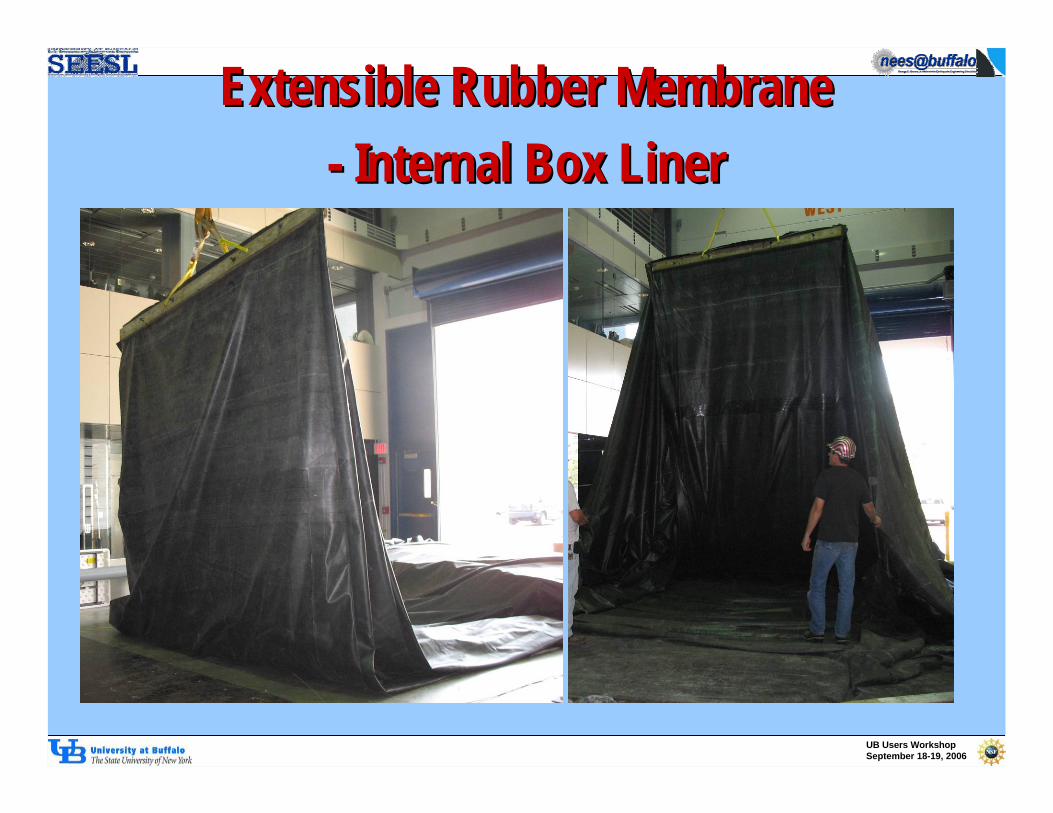
Extensible Rubber MembraneExtensible Rubber Membrane-- Internal Box LinerInternal Box Liner

UB Users WorkshopUB Users WorkshopSeptember 18September 18--19, 200619, 2006
Ottawa F55 Sand; 145 Tons Ottawa F55 Sand; 145 Tons availableavailable
Soils Data Report Soils Data Report –– Grain Size, Grain Size, UndrainedUndrained Cyclic Triaxial Data & Cyclic Triaxial Data & Monotonic Triaxial Data Available Monotonic Triaxial Data Available (Thevanayagam et al. 2003)(Thevanayagam et al. 2003)
User is responsible for new material, User is responsible for new material, removal, and handlingremoval, and handling
SoilSoil

UB Users WorkshopUB Users WorkshopSeptember 18September 18--19, 200619, 2006
Sand Construction MethodSand Construction Method--Hydraulic FillingHydraulic Filling
Hydraulic Pumps (5hp; 1hp) & 3” Dia Hoses Available – Useable from March to November
UB Users WorkshopUB Users WorkshopSeptember 18September 18--19, 200619, 2006
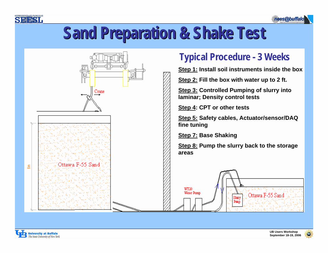
Sand Preparation & Shake TestSand Preparation & Shake Test
Step 1: Install soil instruments inside the box
Step 2: Fill the box with water up to 2 ft.
Step 3: Controlled Pumping of slurry into laminar; Density control tests
Step 4: CPT or other tests
Step 5: Safety cables, Actuator/sensor/DAQ fine tuning
Step 7: Base Shaking
Step 8: Pump the slurry back to the storage areas
Typical Procedure - 3 Weeks

UB Users WorkshopUB Users WorkshopSeptember 18September 18--19, 200619, 2006
Hydraulic Filling TrialHydraulic Filling Trial
• Water depth= 1 – 3 ft
• Discharge Pipe horizontally moving
• Diffuser & Nozzle vertical

UB Users WorkshopUB Users WorkshopSeptember 18September 18--19, 200619, 2006
Soil Placement DensitySoil Placement Density
Depending on discharge velocity and discharge configurations relative density can be controlled within a narrow range.
Density limits - About 30% to 70%.
Users must develop/decide on hydraulic placement methods and controls.

UB Users WorkshopUB Users WorkshopSeptember 18September 18--19, 200619, 2006
Typical InstrumentationTypical Instrumentation
UB Users WorkshopUB Users WorkshopSeptember 18September 18--19, 200619, 2006
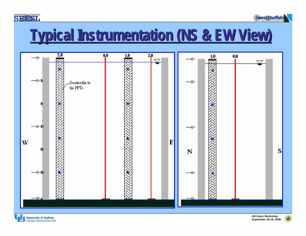
Typical Instrumentation (NS & EW View)Typical Instrumentation (NS & EW View)

UB Users WorkshopUB Users WorkshopSeptember 18September 18--19, 200619, 2006
Shape Acceleration ArrayShape Acceleration ArrayFeaturesFeatures¾”¾” Diameter Cable Diameter Cable enclosing 3 MEMS enclosing 3 MEMS Accelerometers Accelerometers (X,Y,Z) at 1(X,Y,Z) at 1--ft ft intervalinterval
Total Length = 24 ftTotal Length = 24 ft
Total Arrays = 4Total Arrays = 4
Used to measure Used to measure acceleration profile acceleration profile with depth, and with depth, and displacement profile displacement profile with depthwith depth
RealReal--time time acceleration and acceleration and shape displayshape display

UB Users WorkshopUB Users WorkshopSeptember 18September 18--19, 200619, 2006
Typical Instrumentation TableTypical Instrumentation Table

UB Users WorkshopUB Users WorkshopSeptember 18September 18--19, 200619, 2006
Typical Ground MotionTypical Ground Motion
-1.0
-0.5
0.0
0.5
1.0
0 5 10 15 20 25 30 35
Time(s)
Dis
plac
emen
t (in
)
-0.4-0.3-0.2-0.10.00.10.20.30.4
0 5 10 15 20 25 30 35Time (s)
Acc
eler
atio
n (g
)
Any Earthquake or Synthetic Motion Possible subject to umax= ±6’’ & Overturning Safety considerations.
Horizontal actuator Capacity = Two 100 ton displacement controlled dynamic actuators
-0.006-0.004-0.0020.0000.0020.0040.006
0 1 2 3 4 5Time (s)
Acce
lera
tion
(g)

UB Users WorkshopUB Users WorkshopSeptember 18September 18--19, 200619, 2006
Typical Schedule for Shake Tests Typical Schedule for Shake Tests Task Name Duration Start Finish
Preparatory Shake Tests 28 days Mon 9/18/0 Wed 10/25/03m Box Test 14 days Mon 9/18/0 Thu 10/5/0
Fill the box with water for leak tes 2 days Mon 9/18/0 Tue 9/19/0Reduce water level to 2ft 1 day Wed 9/20/0 Wed 9/20/0Pump the slurry to theLB up to 3m 3 days Thu 9/21/0 Mon 9/25/0Cone & Bucket Density Tests 3 days Thu 9/21/0 Mon 9/25/0CPT 1 day Tue 9/26/0 Tue 9/26/0Remove top 3m rings 1 day Wed 9/27/0 Wed 9/27/0Install accelerometers top of the 1 day Wed 9/27/0 Wed 9/27/0Safety Cables; Shaking/Actuator 3 days Wed 9/27/0 Fri 9/29/0NDS & DS Shaking 1 day Mon 10/2/0 Mon 10/2/0Pump the slurry back to the stora 3 days Tue 10/3/0 Thu 10/5/0
Test LG-O 14 days Fri 10/6/0 Wed 10/25/0Put soil instruments inside the bo 2 days Fri 10/6/0 Mon 10/9/0Fill the box with water up to 2ft 0.5 day Tue 10/10/0 Tue 10/10/0Pump the slurry to theLB 3.5 day Tue 10/10/0 Fri 10/13/0Cone & Bucket Density Tests 4 days Tue 10/10/0 Fri 10/13/0CPT 1 day Mon 10/16/ Mon 10/16/Safety cables, Actuator/sensor/D 1 day Tue 10/17/0 Tue 10/17/0NDS & DS Shaking 1 day Wed 10/18/ Wed 10/18/CPT 1 day Thu 10/19/0 Thu 10/19/0Pump the slurry back to the stora 4 days Fri 10/20/0 Wed 10/25/
17 24 1 8 15 22Sep 17, '06 Sep 24, '06 Oct 1, '06 Oct 8, '06 Oct 15, '06 Oct 22, '0
Allow a LOT of time for Detailed Planning

UB Users WorkshopUB Users WorkshopSeptember 18September 18--19, 200619, 2006
Safety, Safety, Safety Safety, Safety, Safety
Overturning
Excessive sliding
Water leakage
Overloading
Quicksand/sand boils
Dust exposure
Etc.
Etc.
Etc.

UB Users WorkshopUB Users WorkshopSeptember 18September 18--19, 200619, 2006
Thank YouThank You
Questions?Questions?

UB Users WorkshopUB Users WorkshopSeptember 18September 18--19, 200619, 2006
Ongoing Research Ongoing Research ……....““Experimental and Micromechanical Computational Study of Pile Experimental and Micromechanical Computational Study of Pile Foundations Subjected to LiquefactionFoundations Subjected to Liquefaction--Induced Lateral SpreadingInduced Lateral Spreading””
•• A NEESRA NEESR--SG Grant involving: Rensselaer Polytechnic Institute, UniversitySG Grant involving: Rensselaer Polytechnic Institute, University at at Buffalo, University of CaliforniaBuffalo, University of California--San Diego, Tulane, NIED, and Tokyo Institute of San Diego, Tulane, NIED, and Tokyo Institute of TechnologyTechnology
•• Leveraging off of the facility infrastructure at the UBLeveraging off of the facility infrastructure at the UB--NEES Site; Reaction Wall, NEES Site; Reaction Wall, Strong Floor, Dynamic ActuatorsStrong Floor, Dynamic Actuators--High Performance Hydraulic System, 2High Performance Hydraulic System, 2--D D Geotechnical Laminar Box and DAQ and Image processing, tests wilGeotechnical Laminar Box and DAQ and Image processing, tests will be l be performed in years 1performed in years 1--4 (20054 (2005--2008)2008)
Pile Group. Single Piles
5 .0 m
2.75
m
6 .2 m
S E C T IO N A L V I E W
P L A N
S h a k i n g F ra m e o n S tro n g F lo o r
P ile
α = 2 o r 3 d eg .
N e v a d a S a n d , D r~ 4 5 %
3.35
m
5 .6 m
2 -D L a m in a r B o x (2 4 L a m in a te s )
B a ll B e a r in g s
(E I) 1
(E I)2> > (E I)1
S e e n o te s b e lo w
5 .0 m
2.75
m
6 .2 m
S E C T I O N A L V I E W
P L A N
S h a k in g F ra m e o n S tro n g F lo o r
G ro u p P i le
α = 2 o r 3 d eg .
N e va d a S a n d , D r~ 4 5 %
3.35
m
5 .6 m
2 -D L a m in ar B o x (2 4 L a m in a te s)
B a ll B e a rin g s
S e e n o te s b e lo w

UB Users WorkshopUB Users WorkshopSeptember 18September 18--19, 200619, 2006
Ongoing Research Ongoing Research …… ((ConCon’’tt))•• The 2The 2--D Geotechnical Laminar Box is deployed on a 12D Geotechnical Laminar Box is deployed on a 12’’x26x26’’ steel plate steel plate
leveled and secured to the strong floor upon which 240 ball bearleveled and secured to the strong floor upon which 240 ball bearings ings integrated into the base assembly will allow 2integrated into the base assembly will allow 2--D motions.D motions.
•• Two dynamic actuators deployed against the Two dynamic actuators deployed against the reaction wall will be used to reaction wall will be used to ““shakeshake”” the the 170 ton assembly containing 80170 ton assembly containing 80--cubic meters cubic meters of sand.of sand.

UB Users WorkshopUB Users WorkshopSeptember 18September 18--19, 200619, 2006
•• Understand Understand the phenomenon of sand the phenomenon of sand liquefaction during lateral spreading near pile liquefaction during lateral spreading near pile foundations; foundations;
•• Solve Solve the engineering questions on how to the engineering questions on how to design pile foundations against lateral design pile foundations against lateral spreading both in simplified terms as well as in spreading both in simplified terms as well as in terms of providing a basic understanding for terms of providing a basic understanding for appropriate analytical platforms; and appropriate analytical platforms; and
•• Clarify Clarify the correct way to use centrifuge the correct way to use centrifuge modeling in future research and engineering modeling in future research and engineering applications. applications.
•• Research plan also involvesResearch plan also involves–– UB NEES 1g 2D shaking, 6mUB NEES 1g 2D shaking, 6m--tall laminar boxtall laminar box–– RPI NEES centrifuge facility, and ERPI NEES centrifuge facility, and E--Defense Miki Defense Miki
CityCity–– Advanced sensors and DEM & FEM AnalysesAdvanced sensors and DEM & FEM Analyses
Research ObjectivesResearch Objectives

UB Users WorkshopUB Users WorkshopSeptember 18September 18--19, 200619, 2006
UB Site UB Site –– Test ScheduleTest Schedule
Equipment Modification & Calibrations (9/05-8/06)
Free-Field Liquefaction Tests – (9/06-10/06)Single Pile – Lateral Spreading – (10/06-5/07)Group Pile – Lateral Spreading – (5/07-8/07)Group Pile – Lateral Spreading (orthogonal
shaking) –(9/07-11/07)

UB Users WorkshopUB Users WorkshopSeptember 18September 18--19, 200619, 2006
5.0 m
2.75 m
6.2 m
SECTIONAL VIEW
PLAN
Shaking Frame on Strong Floor
Pile(Test 1A: High EI pile,Test 1B: Low EI pile)
α=2 or 3 deg.
F#55Sand, Dr~45%
3.35 m
5.6 m
2-D Laminar Box (24 Laminates)
Ball Bearings
Single Pile (Tests 1 & 2)Single Pile (Tests 1 & 2)(shaking in perpendicular directions)(shaking in perpendicular directions)

UB Users WorkshopUB Users WorkshopSeptember 18September 18--19, 200619, 2006
Group Pile (Tests 3 and 4)Group Pile (Tests 3 and 4)(shaking in perpendicular directions)(shaking in perpendicular directions)
5.0 m
2.75 m
6.2 m
SECTIONAL VIEW
PLAN
Shaking Frame on Strong Floor
Pile
α=2 or 3 deg.
F#55Sand, Dr~45%
3.35 m
5.6 m
2-D Laminar Box (24 Laminates)
Ball Bearings
Pile Cap

UB Users WorkshopUB Users WorkshopSeptember 18September 18--19, 200619, 2006
SoilSoil--Pile InstrumentationPile Instrumentation
Schematic Diagram- Sectional ViewsStrain Gauge Piezometer Accelerometer Potentiometer
MEMS ShapeCable

UB Users WorkshopUB Users WorkshopSeptember 18September 18--19, 200619, 2006
SoilSoil--Pile InstrumentationPile Instrumentation
Schematic Diagram – Plan View
Strain Gauge Piezometer Accelerometer Potentiometer MEMS Shape Cable
Reaction Wall
Actuator

UB Users WorkshopUB Users WorkshopSeptember 18September 18--19, 200619, 2006
Instrumentation SummaryInstrumentation SummarySoil SensorsSoil Sensors•• 34 Accelerometers34 Accelerometers•• 54 Piezometers54 Piezometers•• 40 Potentiometers 40 Potentiometers •• 4 MEMS Shape Cables & Accelerometers4 MEMS Shape Cables & Accelerometers•• Krypton Imager Krypton Imager –– Field of ViewField of View•• Digital VideoDigital Video
Pile SensorsPile Sensors•• Many Strain gaugesMany Strain gauges•• 2 MEMS Shape Cables2 MEMS Shape Cables•• Krypton Imager Krypton Imager -- Field of View: Pile CapField of View: Pile Cap

UB Users WorkshopUB Users WorkshopSeptember 18September 18--19, 200619, 2006
•• Laminar Box Shaking System Development & Laminar Box Shaking System Development & Shaking ControlsShaking Controls
•• Hydraulic Fill Sand Construction & Density Hydraulic Fill Sand Construction & Density ControlsControls
•• Instrumentation Procurement & CalibrationsInstrumentation Procurement & Calibrations•• Project Test Plans & Instrumentation PlansProject Test Plans & Instrumentation Plans•• Laminar Box Laminar Box -- Free Field Liquefaction Testing Free Field Liquefaction Testing
–– (in progress) (in progress) •• Data Archival PlansData Archival Plans
YearYear--1 Progress 1 Progress SummarySummary

UB Users WorkshopUB Users WorkshopSeptember 18September 18--19, 200619, 2006
Ground MotionGround Motion
-1.0
-0.5
0.0
0.5
1.0
0 5 10 15 20 25 30 35
Time(s)
Dis
plac
emen
t (in
)
-0.4-0.3-0.2-0.10.00.10.20.30.4
0 5 10 15 20 25 30 35Time (s)
Acc
eler
atio
n (g
)
umax= ±0.74’’
umin= ±0.01’’
f = 2 Hz
-0.006-0.004-0.0020.0000.0020.0040.006
0 1 2 3 4 5Time (s)
Acce
lera
tion
(g)

UB Users WorkshopUB Users WorkshopSeptember 18September 18--19, 200619, 2006
Thank You !Thank You !
Questions ?Questions ?