universiti teknikal malaysia melaka - eprints.utem.edu.myeprints.utem.edu.my/19499/1/five-axis tool...
TRANSCRIPT

UNIVERSITI TEKNIKAL MALAYSIA MELAKA
FIVE-AXIS TOOL PATH PROGRAMMING UTILIZING CATIA V5
FOR TURBINE BLADE: ALUMINIUM 6063
This report submitted in accordance with requirement of the Universiti Teknikal
Malaysia Melaka (UTeM) for the Bachelor’s Degree in Manufacturing Engineering
Technology (Process and Technology) (Hons.)
by
LIM RU PEI
B071310514
930722-07-5356
FACULTY OF ENGINEERING TECHNOLOGY
2016
i
DECLARATION
I hereby, declared this report entitled “FIVE-AXIS TOOL PATH PROGRAMMING
UTILIZING CATIA V5 FOR TURBINE BLADE: ALUMINIUM 6063” is the results of
my own research except as cited in references.
Signature : ………………………
Name : LIM RU PEI
Date : ………………………

ii
APPROVAL
This report is submitted to the Faculty of Engineering Technology of UTeM as a
partial fulfilment of the requirements for the degree of Bachelor of Manufacturing
Engineering Technology (Process and Technology) with Honours. The member of
the supervisory is as follow:
……………………………….
(SYAHRUL AZWAN BIN SUNDI @ SUANDI)

iii
ABSTRAK
Melalui kajian ini, semua maklumat, jurnal, artikel yang berkaitan dengan CAD/CAM,
turbine blade dan five-axis machining pergerakan mata alat bagi peningkatan
pengetahuan tentang projek ini. Pada masa kini, sesetengah masalah telah dihadapi
berdasarkan turbine blade seperti kecacatan atas sebab manufacturing process. Objektive
bagi projek ini ialah mengeluarkan give-axis machining pergerakan mata alat yang
sesuai serta ketepatan bagi machined part. CAD model telah didapati dari GrabCAD.
Perubahan telah dijalankan berdasarkan peralatan dan bahan mentah yang sedia ada.
Aluminium 6063 telah digunakan sebagai bahan mentah bagi turbine blade. Five-axis
machine yang code DMU 60 monoBLOCK telah digunakan bagi menghasilkan turbine
blade serta strategi pemesinan telah disediakan melalui CATIA V5. Dalam CADCAM
software, ,beberapa strategi telah digunakan seperti roughing process, multi-axis flank
contouring, multi-axis sweeping dan isoparametric. Selepas proses pemesinan fizikal,
penilaian telah dijalankan 3D Scanner serta its methodology. Keputusan yang didapati
dari 3D Scanner telah dinyatakan perbezaan CAD model dengan bahagian dimesin
fizikal melalui warna yang berbeza. Warna biru mewakili kelebihan pemotongan serta
warna hijau mewakili kelebihan bahan.
Kata Kunci: Turbine Blade; Five-axis Pergerakan Tool; Mesin CNC; CATIA V5;
Ketepatan
iv
ABSTRACT
In this research, information’s, journals and articles regarding CAD/CAM turbine blade
and five-axis machining tool path have been searched for better acknowledgement and
understanding. Currently, some problem has been occurred in turbine blade such as
premature failure of blade caused by serious manufacturing defects. Objectives of this
research are producing suitable machining cutting tool path utilizing CATIA V5 and
accuracy is investigated. Turbine Blade CAD model has been selected from GrabCAD.
Modification has been done based on limitation of equipment and raw material.
Aluminium 6063 is used as raw material to machine turbine blade. DMU 60
monoBLOCK is used in machining turbine blade and machining program has been done
by CATIA V5. In CADCAM software, machining strategies have been used to machine
turbine blade are roughing process, multi-axis flank contouring, multi-axis sweeping and
isoparametric. After physical machining process, analysis has been done through 3D
Scanner and its methodology. Result from 3D Scanner show comparison between CAD
model and physical machined part by different type of colour. Blue colour shows overcut
while green colour shows undercut. Some recommendations such as smaller and tapered
cutting tool has been suggested in part of future work.
Keywords: Turbine Blade; Five-axis Tool Path; CNC machine; CATIA V5; Accuracy

v
DEDICATIONS
To my beloved family

vi
ACKNOWLEDGMENTS
Firstly, I would like to thanks to my beloved university, Universiti Teknikal
Malaysia Melaka (UTeM) giving me this opportunity to explore myself in new thing. I
would like to thanks God for blessings to allow me complete my Final Year Project
smoothly although there are some problems faced in Final Year Project.
I wish to express my fully thanks to my Supervisor, Mr. SYAHRUL AZWAN
BIN SUNDI @ SUANDI and co-supervisor Mr. MUHAMMAD SYAFIK BIN JUMALI
for the motivation, enormous amount of knowledge and patience. Both of supervisor
have guide me and give useful information in all the time of research study.
Besides, I like to take this opportunity to express my gratitude to all assistance
engineers in UTeM which given fully assistance to me for this research study.
Last but not the least; I here to thank my family and friends for the continuously
encouragement, care and support me toward this project.

vii
TABLE OF CONTENT
DECLARATION ................................................................................................................ i
APPROVAL ....................................................................................................................... ii
ABSTRAK ........................................................................................................................iii
ABSTRACT ...................................................................................................................... iv
DEDICATIONS ................................................................................................................. v
ACKNOWLEDGMENTS ................................................................................................ vi
TABLE OF CONTENT ………………………………………………………………...vii
LIST OF FIGURE ………………………………………………………………………ix
LIST OF TABLE ………………………………………………………………………xiii
LIST OF ABBREVIATIONS, SYMBOLS AND NOMENCLATURE ……………….xiv
CHAPTER 1 INTRODUCTION 1
1.1 Background ........................................................................................................... 1
1.2 Problem statement ................................................................................................. 4
1.3 Objectives .............................................................................................................. 5
1.4 Scope ..................................................................................................................... 5
CHAPTER 2 LITERATURE REVIEW ............................................................................. 6
2.1 Five-Axis Machining ............................................................................................ 6
2.2 Ball-end Milling process ..................................................................................... 17
2.3 Five-axis Flank Milling ....................................................................................... 21
2.4 Turbine blade ....................................................................................................... 26
2.5 Accuracy of Five-axis machining........................................................................ 27
2.6 Aluminum ............................................................................................................ 28
CHAPTER 3METHODOLOGY ..................................................................................... 32
3.1 Project planning .................................................................................................. 32
3.2 Phase I ................................................................................................................. 35
3.2.1 Problem Simulation……………………………………………………...35
3.2.2 Literature Review to Understand Better The Topic……………………...35
3.2.3 Searching Suitable CAD Model Verification……………………………36
3.2.4 Assembly Process of CAD Part………………………………………….38

viii
3.3 Phase II ................................................................................................................ 39
3.3.1 Material and Suitable Cutting Tool………………………………………39
3.3.2 Preparation of CAM Program……………………………………………42
3.3.2.1 Process Roughing………………………………………………..45
3.3.2.2 Process Multi-axis Sweeping…………………………………….47
3.3.2.3 Process Isoparametric……………………………………………51
3.3.2.4 Process Multi-axis Flank Contouring……………………………55
3.3.3 Jig and Fixture Preparation………………………………………………58
3.3.4 Post Processing…………………………………………………………..60
3.3.5 Physical Machining……………………………………………………...61
3.3.6 Dimensional Analysis…………………………………………………....63
CHAPTER 4 RESULT AND DISCUSSION ................................................................... 67
4.1 Result .................................................................................................................. 67
4.2 Comparison between Finished Part and CAD Model in CAM Program ............ 70
4.3 Problem Preparation of Jig .................................................................................. 72
4.4 Machined Part Problem ....................................................................................... 75
4.5 Accuracy of Turbine Blade.................................................................................. 76
CHAPTER 5 CONCLUSION AND FUTURE WORK ................................................... 80
5.1 Conclusion .......................................................................................................... 80
5.2 Future Work ......................................................................................................... 81
REFERENCES………………………………………………………………………….82
ix
LIST OF FIGURE
Figure 2.1: The Pressure Surface after Removing Tool Marks. 8
Figure 2.2: Impeller that been machined. 8
Figure 2.3: Types of general ball end mills. 11
Figure 2.4: Comparison of machining strategies. 11
Figure 2.5: A View of Model Gampad machined is zoom in by ISFC
(Improved Space Filling Curve) and traditional SFC (Space Filling Curve). 12
Figure 2.6: The surface partitioning and model for a blade of a blisk. 14
Figure 2.7: Tool Paths have been shown for two sub surfaces. 15
Figure 2.8: Flank Milling Operation in Case Study. 16
Figure 2.9: Resulting Surfaces after The Tests 18
Figure 2.10: In Test 1, Tool Tip Mark has been Observed while Test Two does
not Exist Tool Tip Mark on the surface. 19
Figure 2.11: Lead and Tilt Angles Will Affected on Case 1 -Maximum Fxy
Force, Figure B Represents Case 2 while Figure C which Related with Tool
Deflection for case3.
19
Figure 2.12: The Geometry Applied for Purpose of Simulation and Validation. 20
Figure 2.13: Geometry Output of Five-axis Machining of An Impeller has
been Shown by Developed through Developed Model 20
Fig. 2.14: Process of End Milling, Flank Milling and Sweeping.
Red colour shows contact locations of cutter with surface. 22
Figure 2.15: References of Main Generation of Flank Milling Toolpath. 23
x
Fig. 2.16: Fig. 2.16: Surface A Error-measuring Result. 25
Figure 2.17: Finished Part 26
Figure 2.18: (a)Cone defining the boundary of meshed blade1; (b)generated
toolpath. 27
Figure 2.19: (a) Cones defining the machining region for meshed blade2;
(b)the generated toolpath for the given region 27
Figure 2.20: Figure 2.20: Designation System of Wrought Aluminium Alloy 31
Figure 2.21: Different Advantage of Aluminium With Different Combination
of Material. 31
Figure 3.1: Flow Chart of Methodology 33
Figure 3.2: Selected CAD Model -Turbine Blade 36
Figure 3.3: CAD Model (Turbine Blade) with Stock and Plane System 38
Figure 3.4: Plane System 38
Figure 3.5: Assembly Part (CAD Model with Plane System) 39
Figure 3.6: Detail Regarding Cutting Tool 41
Figure 3.7: List of Cutting Tool Used 42
Figure 3.8: Setting of Part Operation 42
Figure 3.9: Flow Chart of CAM Machining Process 44
Figure 3.10: First Roughing 46
Figure 3.11: Second Roughing 47
Figure 3.12: Labelling Number on Space between Blades based on Labelling
of Multi-axis sweeping
51

xi
Figure 3.13: Tool Path for Front of Blade 58
Figure 3.14: Tool Path for Back of Blade 58
Figure 3.15: Drawing of Jig 59
Figure 3.16: Jig for CNC Five-axis Machining 60
Figure 3.17: Example of G-Code and M-Code in H. file Format 61
Figure 3.18: Technical Data of DMU 60 monoBLOCK Machine 62
Figure 3.19: DMU 60 monoBLOCK Machine 62
Figure 3.20: Program Simulation for Validation Test Cut 63
Figure 3.21: Physical Machining of First Blade 63
Figure 3.22: Function of 3D Scanner 64
Figure 3.23: Example Flow Chart of 3D Scanner 65
Figure 3.24: 3D Scanner Model 65
Figure 3.25: a) Before Applying Spraying Substances on Turbine Blade.
b) After Appling Spraying Substances on Turbine Blade
66
Figure 4.1: Result of CAM Program Simulation 68
Figure 4.2: Result of Physical Machining 68
Figure 4.3: Result of 3D Scanner 69
Figure 4.4: Comparison of Physical Part and CAD Model 69
Figure 4.5: Comparison between Finished Part in CAM Program and Model 72
Figure 4.6: Fillet Welding 73

xii
Figure 4.7: Problem during Welding Jig 74
Figure 4.8: Welded Jig 74
Figure 4.9: Problem of Machined Part 75
Figure 4.10: Offset of Tool Path 76
Figure 4.11: Cutting Tool Path 76
Figure 4.12: Overall Result of 3D Scanner 77
Figure 4.13: Side View of 3D Scanner Result 78

xiii
LIST OF TABLE
Table 3.1: Scale Ratio of CAD Model 37
Table 3.2: Detail
Dimension of Selected Cutting Tool
41
Table 3.3: Setting of Roughing Process 46
Table 3.4: Setting of Multi-axis Sweeping 48
Table 3.5: List of Lead and Tilt Angle for Each Multi-Axis Sweeping 50
Table 3.6: Tool Path of Isoparametric on Different Machining Surface 52
Table 3.7: Setting of Isoparametric 53
Table 3.8: Setting of Multi-axis Flank Contouring 55
Table 4.1: Comparison with and without Setting of Offset Value and Check 70
Table 4.2: Comparison between Tanto Fan and Combin Parelm 71

xiv
LIST OF ABBREVIATIONS, SYMBOLS AND
NOMENCLATURE
CAM = Computer Aided Manufacturing
CAD = Computer Aided Design
CATIA = Computer aided three-dimensional interactive application
NC = Numerical Control
CNC = Computer Numerical Control
Ksi = Kilopound per square inch
IGES = Initial Graphic Exchange Specification
STEP = Standard Exchange of the Product Model
STL = Standard Triangle Language
UTeM = Universiti Teknikal Malaysia Melaka

1
CHAPTER 1
INTRODUCTION
1.1 Background
In current condition, there is a great importance in productive activity which is
machining process for both indirectly for the manufacture of auxiliary elements and
directly in the manufacture of components. Multiple fields related to the machining
technology has evolved much in recent years such as the means of production,
machining technology, tools for cutting, CAD/CAM or the sensors. Technique that
applied in five-axis machining have been evolved rapidly with many CAD/CAM
software developers. CAD/CAM software have addition function such as
collision-avoidance capabilities and advanced simulation for five-axis program.
CAD/CAM software is designed to cut the complex parts used in many areas such as
die-mold, aerospace and medical machining applications. (Patrick Waurzyniak, 2007).
CNC machining means the physical machining process which is controlled under a
NC program. A programmer must specify machine activity in NC program and cutting
tool movement based on the sequence of the machining process. NC program execute
instructions and interpret it through the machine control unit (MCU) of the NC machine.
There are three types of NC programming which are manual programming, CAD- assisted
programming and computer-assisted programming which based on the level of
automation.
CAD systems is used to define, edit and verify the actual cutter motion and also to
define the part geometry. This system can help in achieved high performance levels of
automation. Nowadays, there are several CAD/CAM systems support the capability to

2
generate instructions of NC machining which based on the definition of geometry for a
cutter and workpiece, such as CADCAM, CATIA and Computer vision.
Delcam plc (Birmingham, UK) has been develop CAM software and also made
moves on the acquisition front, purchasing IMCS Inc. PartMaker (Fort Washington, PA)
after their company buys Engineering Geometry Systems (Salt Lake City), developers of
FeatureCAM. (Patrick Waurzyniak, 2007)
Recently, five-axis and multi-axis machining methods have been looked by CAM
software suppliers to solidify their offerings for users trying to stay competitive by using
more complex manufacturing techniques. In getting keen interest in multi-axis and
five-axis machining, there are manufacturers who play important role such as Eastern
European and Asian manufacturers. Aim of those manufacturers are getting lower cost
for tools used in five-axis machine tools and intense competition from low-cost. To
reduce setups on machining complex parts, new five-axis offerings add the ability.
Infinite probability things such as to shapes and the part sizes which can
manufactured effectively by five-axis machining. The cutting tool on a center of
five-axis machining moves across the linear axes which are X, Y and Z axes together
with rotates on the B and A axes to machine the workpiece/ part from any direction. On
the other hand, five-axis machining can manufacture five sides of a single part in single
settings. (Mazak) Based on explanation of Gibbs (Rolls-Royce), Five-axis technology
provides the user with the ultimate amount of control when applying tooling to a part.
Because of this, collision avoidance, improved surface finish, and reduced tool wear are
some of the benefits realized. (Stuart Nathan, 2015)
One of the leading solutions for product success is CATIA V5. CATIA V5 is a
software that addresses all organizations related with manufacturing field which from
minor independent manufacturer until their supply chains. CATIA software is suitable to
a wide variety of industries such as industrial machinery and automotive, aerospace,
electronics, building of ship, consumer goods and plant design. Nowadays, one of
function using CATIA is designing anything in the world which from a clothing and
3
jewelry to an airplane. Product engineering in a fully-integrated manner with functional
range and power is provided by CATIA to obtain the complete product development
process. CATIA helps to increase response of enterprises to market needs shorten
development cycles and facilitates reuse of product design knowledge.
An old method to create turbine blade was metalworking. To create turbine blades
used for jet engines, the most basic and ancient methods of metalworking are casting
process. If a fire can be heated until temperature which can melt a metal, a crucible is
created to melt metal together with a mold (can withstand the heat) and cast complex
forms of metal. “The blades operate in an environment several hundreds of degrees
hotter than the melting point of the nickel alloy, but because of the cooling mechanisms,
the metal is never above its melting point, even though the environment is.” (Neil Glover,
Rolls-Royce). Not all material in making turbine blades is nickel alloy; family of alloys
and ceramic materials also used in making turbine blades. A significant differentiation
between temperature of external flow and surface temperature. Material with a high
melting point is used in solving the problem and reduces the effective temperature over
the surface of the used metal. (Stuart Nathan, 2015)
In the periodic table, the 13th element is aluminium which is a silvery-white metal.
Aluminium is the metal that widely disseminated on Earth. This statement can be proved
as more than 8% of the Earth's core mass is aluminium. After oxygen and silicon, the
third most common chemical element on earth is aluminium. (Ivan Aivazovsky) There
are increasing requirements for those projects which involved aluminium have become
more familiar as aluminium has become an excellent alternative method of steel. In
welding fabrication industry, many applications are applied together with the growth of
aluminum. The advisable way to understand aluminium clearly is starting by become
familiar with the aluminum designation system/ identification. Currently, many types of
aluminum alloys are available and have their characteristics. Nowadays aluminum alloys
make up a wide and multifunctional range of manufacturing materials which together
with their various tempers. The difference between many available alloys and their
various properties is very important step for optimum product design. (ESAB knowledge
4
center). One of aluminium alloys is 6xxx series are combination aluminium with silicon
and magnesium. 6xxx series aluminium alloys are moderate in strength which is 200 to
350 MPa. Though the heat treatment processing or forming process, the strength of
aluminium 6xxx series are achieved. (sapa:)
1.2 Problem statement
At present, one of causes failure of blade is manufacturing defects. Defects often
occur as design specification of blades which based on CAD models or drawings are not
follow during manufacturing process. One of the common defects is premature failure of
blade as it is weakening the point that normal loads by serious manufacturing defects.
Turbine blades are designed for mass center location and optimum aerodynamics,
resist extreme temperature, and avoid corrosion, and constitute of advanced metal alloy
castings and composites to increase strength. Tight tolerances apply to both the
geometry and alignment of turbine blades to guarantee optimum blade position and
aerodynamic operation. (Nikon)
Currently, process of manufacturing turbine blades are castings, forgings, solid
billets of titanium and stainless steel or bar stock. (Mark Albert ,2012) Many factors are
important such as total cut time, depth of cut, spindle speed, an investment in the
machine itself and tool life in determining material of manufacturing process. These
factors contribute to cost of manufacturing and in turn the ability to efficiently and
profitably machine selected material.
By machining, manufacturing defects of turbine blade may be reduced. Five-axis
CNC machining is suitable to machine complex part. Five-axis CNC machining provides
a high quality of product or part and given good positional accuracy. Simulation done in
software such as CATIA V5 helps in determining defect occur before physical
machining. This step helps in preventing wasted material.

5
1.3 Objectives
The objectives of this project are stated as below:
a) To determine the suitable machining tool path in preparing the CAM program for a
turbine blade utilizing CATIA V5 by validating the tool path in the real machining
which is 5-axis machine.
b) To investigate the effect of dimensional accuracy of a machined part in transferring
the CADCAM data to the actual machined part.
1.4 Scope
In this research, things included and limitations of this project are discussed. There
are limitations in this project as it is impossible to include everything in the project. This
project is concerned on getting the suitable machining tool path generations in producing
one turbine blade utilizing CATIA V5 as the main CAD/CAM software. Material used in
validating the tool path for the physical machining is Aluminum 6063. CAD model of
turbine blade is searched and verified by adviser. This step is very important in ensuring
that the chosen CAD model fulfil the project requirement. Various five axis tool paths/
processes designed to obtain desired turbine blade. Processes that been selected in this
research are roughing multi-axis sweeping, multi-axis flank contouring and
isoparametric. Five-axis machine DMU 60 monoBLOCK is used to perform the
machining. Accuracy of machined part has been analysis after physical machining. 3D
Scanner which located in Rapid Prototyping Lab is used. 3D Scanner can provide fast
and good accuracy result which shows comparison machined part with the original CAD
model and define them based on different type of colour. Dimensional accuracy is
important factor in machining turbine blade.

6
CHAPTER 2
LITERATURE REVIEW
2.1 Five-Axis Machining
A study which related with a new method for five-axis tool path optimization has
conducted by Pascal Ray (2008) found that there is remaining some kinematic
performance issues that have been introduced by tool path computation which can
generate slowdown although scientific community has been study the main problems of
five-axis. The goal of this study is to improve machine tool behavior without
deterioration of milled part quality. The kinematic behaviour of the machine tool and the
five-axis machining geometric method is necessary be confronted. There are a lot of
researched in five-axis machining are focusing on methods to figure out tool axis
orientation in order to improve or optimize such as:
The control of interference between part and tool
The quality of the milled surfaces is evaluated.
The interpolation format of the tool path
Free collision positioning of the tool under its environment
As mentioned in chapter one which is introduction, one of purpose of free-form surface
machining is to minimize machining time while machining complex shapes that respect
to the level of quality. Machine tool behavior and milling strategies are leading to
achieve those aims of productivity and quality. The study proposed by Pascal Ray (2008)
was dealing with the relation between productivity and quality. The method presented in
this study is minimization the angular difference between curvature and two successfully
tool axis orientations. After that, this method is applied to the rotation axis coordinates.
The optimization of this study is a minimization of the movement which created by each

7
rotation axis.
The findings of the study written by Hsin-Pao Chen et al. (2009) can help in
removing tool marks of blade surfaces through smoothing five-axis point milling cutter
paths. Machining controlled by five-axis is certain manufacturing strategy to get a
centrifugal compressor impeller efficiently which have characteristic that overlapping,
surface texture and complex geometry with a specified dimensional tolerance. There are
two challenge tasks needed during planning five-axis tool paths to mill impeller. Those
tasks are required as they play role as part in the manufacturing process. Planning of tool
paths in milling impellers by five-axis has faced one challenge part is making decision or
linearization problems by suitable CL data without causing local gouge and global
interference due to the curvature limitation between the impeller surfaces and cutter size.
Another challenging that has been mention is CL data need to be further convert into NC
data which depend on the setting of a selected five-axis machining tool. This study had
focus on the reverse moving movements on axes along five-axis tool paths. Besides, the
step of eliminating a gouge phenomenon on impeller surfaces is presented through
five-axis CNC machine. During finishing process of milling centrifugal compressor
impeller, tool path of linearization problems and reverse movements of moving axes
along a five-axis without interference may causes tool marks leaved by cutter on the
surfaces of impeller. Its three linear axes are used to machine an impeller by a common
five-axis machine tool as guidance for its tool to specified CC (cutter contact) points
which are to be milled on impeller surfaces. Besides, to adjust its axis of cutter to
prevent collision, the two rotational which are rotating axes and tilt angle of the five-axis
machine tool are utilize. In this study, to machine centrifugal compressor impellers is
generated without any tool marks leaved on machined blade surfaces, a useful and
reliable procedure which can be utilized has been established. There is a simple way
which is the procedure can be used conveniently in determining initial five-axis
accessible tool paths for roughing and semi finishing process in condition of considering
a ball end mill and an end mill. Five-axis finish milling of an impeller consider
successful as it does not leave tool marks on impeller surfaces, the effectiveness of this
procedure has been experimentally confirmed. Demonstration by an experimental
machining test which referred to a popular configuration of five-axis machines have
8
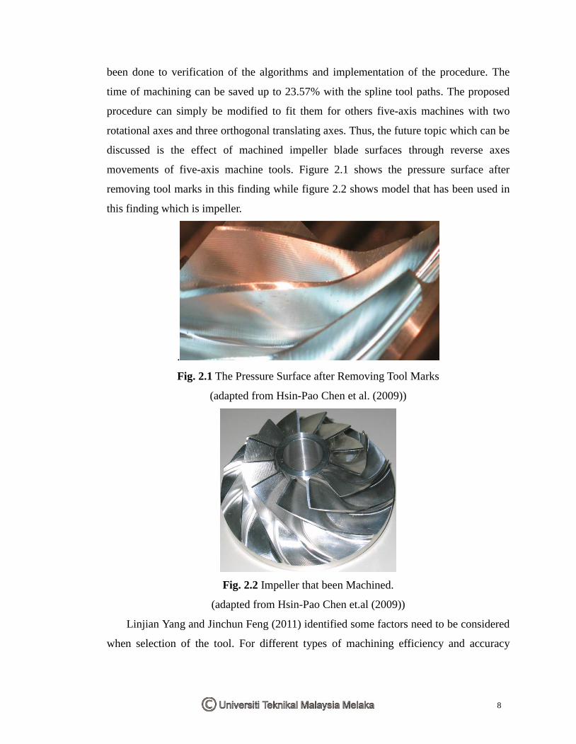
been done to verification of the algorithms and implementation of the procedure. The
time of machining can be saved up to 23.57% with the spline tool paths. The proposed
procedure can simply be modified to fit them for others five-axis machines with two
rotational axes and three orthogonal translating axes. Thus, the future topic which can be
discussed is the effect of machined impeller blade surfaces through reverse axes
movements of five-axis machine tools. Figure 2.1 shows the pressure surface after
removing tool marks in this finding while figure 2.2 shows model that has been used in
this finding which is impeller.
.
Fig. 2.1 The Pressure Surface after Removing Tool Marks
(adapted from Hsin-Pao Chen et al. (2009))
Fig. 2.2 Impeller that been Machined.
(adapted from Hsin-Pao Chen et.al (2009))
Linjian Yang and Jinchun Feng (2011) identified some factors need to be considered
when selection of the tool. For different types of machining efficiency and accuracy

9
requirements in the certain environments, different machine tools are chosen. In
selection of tool, some parameters such as cutting parameter that related to blade and
tool, machine power, the speed of milling material of blade and head are needed to be
calculated. In addition, arbor, blade, cutter head and milling head need to be simulated
and have interference checking depending on posterior simulation processing.
Processing method and Cutter scheme needed modification while cutter interference
exists. Finally, it must be ascertained that cutter has no problem in interference
examination and simulation. In a follow-up study, Linjian Yang and Jinchun Feng (2011)
also found that, in the machine power, machine tool stiffness and speed range of milling
head must be sufficient during simulation. Different diameter cutters are utilized with
these conditions to improve the efficiency of machining by calculating suitable diameter.
At the same time protection of machine tool is paid attention.
Besides, selection of the parametric curve of tool trajectories as the machining direction
of milling when machining blade profile is one of study done by Linjian Yang and
Jinchun Feng (2011). This step helps to improve capability of cutting technology.
Different knife-axial controlling methods and cutters are applied in different areas to
improve efficiency of as possible. Based on simulating machining techniques, key
techniques are proceeded with the development of computers. On the other hand, there
are more preface needed to be consider regarding automatic programming when
five-axis CNC machine is used to machine large blade. Verification of the simulation on
computer is important step before machining. This step can be repeated modification and
optimize processing scheme by machining simulation. Assembling precision in making
uniform welding amount can be greatly improved through the CNC processing way of
groove.
In process a machine tool or CAD/CAM technology is purchased, an important
investment is required and it cannot be done without attentive consideration. Precision,
flexibility and productivity will be limit as technology selected incorrectly. (Arslan
etal.,2004), so companies usually pay attention on technical capabilities and
performance than cost. Comparision between three-axis and five-axis CNC centers in
free-form machining has been done. (WojciechZębala and MalgorzataPlaza ,2014) This
information are useful although although hard material is not used in this project. This