universiti putra malaysia subsonic aeroelastic...
TRANSCRIPT

UNIVERSITI PUTRA MALAYSIA
SUBSONIC AEROELASTIC ANALYSIS OF A THIN FLAT PLATE
DAYANG LAlLA BT. ABANG HAJI ABDUL MAJID
ITMA 2001 6

SUBSONIC AEROELASTIC ANALYSIS OF A THIN FLAT PLATE
By
DAY ANG LAlLA BT. ABANG H AJI ABDUL MAJID
Thesis Submitted in Fulfilment of the Requirement for the Degree of Master of Science in the Institute of Advanced Technology
Universiti Putra Malaysia
March 2001

ii
DEDICATION
Alhamdulillah, thanks to Allah s.w.t. upon the completion of this thesis. This thesis is
specially dedicated to my beloved father, Abang Haji Abdul Majid bin Abang Taha,
who during his lifetime, had continuously stressed on his children to strive for a better
education. I only hope that I have inherited his great wisdom to pass on to my own
. children.
iii
Abstract of thesis presented to the Senate ofUniversiti Putra Malaysia in fulfilment of the requirement for the degree of Master of Science.
SUBSONIC AERO ELASTIC ANALYSIS OF A TIDN FLAT PLATE
By
DAYANG LAlLA BT. ABANG HAJI ABDUL MAJID
March 2001
Chairman: Associate Professor ShahNor Basri, Ph.D., PEngo
Institute of Advanced Technology
The interaction between an aircraft structure and the airflow surrounding it has been
known to severely affect the stability, performance and manoeuvrability of the aircraft.
These interactions form the heart of aero elasticity, a field that comprises all types of
aeroelastic phenomena. In this work, a parametric aeroelastic analysis of a thin flat plate
clamped at the leading edge and exposed to subsonic airflow was conducted. The
aeroelastic effects predicted to occur was flutter, a type of self-excited oscillation.
The analysis was simulated using ZAERO, a panel code aeroelastic program, which
requires free vibration input, obtained using MSC-NASTRAN, a finite element code.
The flutter equation was obtained using Newton's Law of Motion to model the plate
while the airflow was modeled using the Small Disturbance Unsteady Aerodynamic
Theory. Free vibration results and flutter results obtained were validated against
published works found in reference [8, 60 and 61].

iv
The important parameters studied were the aspect ratio and the mass -ratio of the plate.
The effect of the number of free vibration modes employed in the analysis was also
tested. From the results, it was shown that the flutter velocity decreased as the mass
ratio and aspect ratio were increased. The flutter frequency also decreased with higher
mass ratio and at large aspect ratio. The use of a higher number of modes in the flutter
analysis was found to increase the accuracy of the flutter.
Abstrak tesis dikemukakan kepada Senat Universiti Putra Malaysia sebagai memenuhi keperluan untuk Ijazah Master Sains.
v
ANALISIS AEROELASTIK SUBSONIK UNTUK SEBUAH PLAT YANG NIPIS DAN RATA
Oleh
DAYANG LAlLA BT. ABANG HAJI ABDUL MAJID
Mac 2001
Pengerusi: Profesor Madya ShahNor Basri, Ph.D., PEngo
Institut Teknologi Maju
Interaksi antara struktur pesawat dan udara sekelilingnya telah diketahui boleh
mempengaruhi kestabilan, prestasi dan olahgerak pesawat tersebut. Interaksi inilah
yang merupakan nadi keaeroelastikan, suatu bidang yang merangkumi kesemua j enis
fenomena aeroelastik. Dalam kerja ini, analisis parametrik aeroelastik untuk suatu plat
nipis dan rata yang diikat pada hujung mendahulu dan terdedah kepada aliran subsonik
telah dijalankan. Kesan aeroelastik yang dijangka berlaku adalah 'flutter', iaitu sejenis
getaran teruja sendiri.
Simulasi ini telah dijalankan menggunakan ZAERO, perisian aeroelastik berasaskan
kod panel, yang memerlukan input getaran bebas diperolehi menggunakan MSC-
NASTRAN, sebuah kod elemen terhingga. Persamaan untuk 'flutter' diperolehi dengan
menggunakan teori Gerakan Newton untuk model plat dan aliran udara dimodel dengan
menggunakan teori Aerodinamik Gangguan Kecil dan Tak Mantap. Keputusan getaran

vi
bebas dan 'flutter' diperolehi dan disahkan oleh hasil-hasil kerja yang telah diterbitkan
dalam rujukan [8, 60 dan 6 1 ] .
Parameter-parameter penting yang dikaji adalah nisbah aspek dan nisbah jisim plat
tersebut. Kesan daripada bilangan mod getaran bebas yang digunakan dalam analisis
juga dikaji. Daripada keputusan, didapati halaju 'flutter' berkurang apabila nisbah aspek
dan nisbah jisim bertambah. Frekuensi 'flutter' juga didapati menurun dengan
pertambahan nisbah aspek dan nisbah jisim. Penggunaan bilangan mod yang tinggi
dalam analisis 'flutter' didapati telah memperbaiki ketepatan 'flutter'.

vii
ACKNOWLEDGEMENTS
Alhamdulillah, thanks to Allah S.W.t. for the completion of this thesis. I would like to
acknowledge the complete support and advice given by Associate Prof. ShahNor Basri,
my thesis supervisor, throughout the course of my master degree. In spite of all the
'headaches' I put him through, he has consistently put the interest of his students first
and always kept an open door policy.
I am also grateful to Dr. Waqar, Faizal, Aznijar and the rest of the staff in Aerospace
Engineering for their continuous support and kind words. To my wonderful friends, Kak
Ina, Kak Rin, Ila and Kak Milah, thank you for your help and valuable advice. One of
the best things of doing this work was in acquiring friends like you that do not hesitate
to provide shoulders for me to cry on when the going gets too tough.
And lastly, to my wonderful family, your unfailing support and love have encouraged
me at every tum. I will always cherish their constant encouragement during my study
and in my life.

viii
I certify that an Examination Committee met on 22nd March, 2001 to 'conduct the final examination of Dayang Laila bt. Abang Haji Abdul Majid on her Master of Science thesis entitled "Subsonic Aeroelastic Analysis of a Thin Flat Plate" in accordance with Universiti Pertanian Malaysia (Higher Degree) Act 1980 and Universiti Pertanian Malaysia (Higher Degree) Regulation 1981. The Committee recommends that the candidate be awarded the relevant degree. Members of the Examination Committee are as follows:
CHONG FAI KAIT, Ph.D Institute of Advanced Technology Universiti Putra Malaysia (Chairman)
SHAHNOR BASRI, Ph.D Associate Professor, Institute of Advanced Technology Universiti Putra Malaysia (Member)
WAQAR ASRAR, Ph.D Associate Professor, Faculty of Engineering Universiti Putra Malaysia (Member)
FAIZAL MUSTAPHA Faculty of Engineering Universiti Putra Malaysia (Member)
AZAd:11\:10HAYIDIN, Ph.D eputy Dean of Graduate School,
Universiti Putra Malaysia
Date: 0 4 APR 2001

This thesis submitted to the Senate of Universiti Putra Malaysia has been accepted as fulfilment of the requirement for the degree of Master of Science.
M��HAYIDIN' Ph.D ProfessorlDeputy Dean of Graduate School, Universiti Putra Malaysia.
Date:
ix

x
DECLARATION
I hereby declare that the thesis is based on my original work except for quotations and citations which have been duly acknowledged. I also declare that it has not been previously or concurrently submitted for any other degree at UPM or other institutions.
(DA YANG LAlLA BT. ABANG HAJI ABDUL MAJID)
Date: rJ..t A-p"; \ I ::2-00 (

xi
TABLE OF CONTENTS
Page
DEDICATION ABSTRACT
ii 111 v ABSTRAK
ACKNOWLEDGEMENTS APPROVAL SHEETS DECLARATION FORM LIST OF TABLES
vii viii
x xiv xv
xix LIST OF FIGURES LIST OF ABBREVIATIONS
CHAPTER
1. INTRODUCTION
2.
3.
4.
1.1 Introduction 1.2 Panel Flutter 1.3 Scope and Objective of Research
REVIEW OF PREVIOUS WORK
2.1 Engineering Background 2.2 Experimental Aeroelasticity 2.3 Computational Aeroelasticity
2.3.1 Static Aeroelasticity 2.3.2 Dynamic Aeroelasticity
2.4 Closure
THEORY
1 3 5
6
6 8
10 11 15 25
27
3.1 Governing Equation of Motion 27 3.2 Aerodynamic Equation 30
3.2.1 Model of the Fluid Element 31 3.2.2 Integral Solutions to Linearised Small Disturbance Equation 34 3.2.3 Unsteady Boundary Condition and Pressure Coefficients 37
3.3 Flutter Equation of Motion 40 3.4 Closure 42
MODELLING & NUMERICAL METHOD
4.1 Solution Technique 4.1.1 MSC-NASTRAN's Finite Element Method 4.1.2 ZAERO'S Panel Method
43
43 43 45

5.
6.
7 .
4 . 1 .3 Data Transformation Between Finite Element Model and Panel Model
4.2 Solution Algorithm 4.3 Closure
NUMERICAL VALIDATION
5. 1 Validation of Natural Frequencies 5.2 Validation of Flutter 5.3 Closure
RESULTS AND DISCUSSION
6 . 1 General Understanding of ZAERO Results 6.2 Comparison of g- and K-Method 6.3 Flutter Accuracy 6.4 Flutter Comparison of Different Materials 6.5 Parametric Studies
6.5.1 Effects of Small Aspect Ratio 6.5.2 Effects of Large Aspect Ratio 6.5.3 Effects of Mass Ratio 6.5.4 Unsteady Pressure Distribution 6.5.5 Structural Mode Shapes 6.5.6 Flutter Mode Shapes
6.6 Closure
CONCLUSION AND RECOMMENDATION FOR FUTURE WORK
7. 1 Validation of Codes 7.2 Computed Results 7.3 Theoretical Aspects 7.4 Recommendation for Future Work
xii
46
48 53
61
6 1 65 68
7 1
7 1 74 77 80 82 83 85 86 88 89 90 9 1
1 26
1 26 1 27 1 29 1 30
REFERENCES 1 3 1
APPENDICES
Appendix Al Derivation of the Continuity Equation 1 36 Appendix A2 Derivation of the Momentum Equation 13 7 Appendix A3 Derivation of the Unsteady Bernoulli Equation 1 3 8 Appendix A4 Derivation of Linearised Small-Disturbance Velocity 1 40
Potential Equation Appendix A5 Derivation of the Flutter Equation 1 42 Appendix B 1 Finite Element Formulation 1 44 Appendix B2 An Example of MSC-NASTRAN's Output File 1 45 Appendix B3 Description of ZAERO' s Input File 1 68
VITA
Appendix B4 ZAERO's Engineering Application Modules Appendix B5 An Example of Zaero's Flutter Results Using
The g-Method and K-Method Appendix C1 Analytical Calculation of First and Second Natural
Frequency For A Flat Plate
xiii
169 170
184
186

xiv
LIST OF TABLES
Table Page
5.1 Material Properties of Aluminum Plate 69
5.2 Arrangement of Nodes in the x- and y-direction 70
5.3 Comparison of Natural Frequencies 71
5.4 Comparison of Flutter Frequency and Velocity 73
6.1 Flutter Velocity and Frequency at a) AR = 1; b) AR = 5; c) AR = 10; 86
and d) AR =20
6.2 Material Properties of Aluminum 88
6.3 Natural Frequencies for Different Types of Aluminum 88
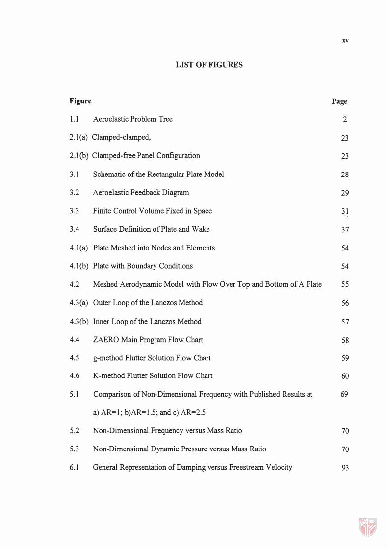
Figure
1.1 Aeroelastic Problem Tree
LIST OF FIGURES
xv
Page
2
2.l(a) Clamped-clamped, 23
2.1 (b) Clamped-free Panel Configuration 23
3.1 Schematic of the Rectangular Plate Model 28
3.2 Aeroelastic Feedback Diagram 29
3.3 Finite Control Volume Fixed in Space 31
3. 4 Surface Definition of Plate and Wake 37
4.l(a) Plate Meshed into Nodes and Elements 54
4.l(b) Plate with Boundary Conditions 54
4.2 Meshed Aerodynamic Model with Flow Over Top and Bottom of A Plate 55
4.3 (a) Outer Loop of the Lanczos Method 56
4.3(b) Inner Loop of the Lanczos Method 57
4.4 ZAERO Main Program Flow Chart 58
4.5 g-method Flutter Solution Flow Chart 59
4.6 K-method Flutter Solution Flow Chart 60
5.1 Comparison of Non-Dimensional Frequency with Published Results at 69
a) AR=l; b)AR=1.5; and c) AR=2. 5
5.2 Non-Dimensional Frequency versus Mass Ratio
5. 3 Non-Dimensional Dynamic Pressure versus Mass Ratio
6.1 General Representation of Damping versus Freestream Velocity
70
70
93

xvi
6.2 General Representation of Frequency versus Freestream Velocity 94
6.3 Damping versus Freestream Velocity: Comparison of g- and K- Method 95
6. 4 Frequency versus Freestream Velocity: Comparison of g- and K-Method 95
6.5 Flutter Frequency versus No.of Modes at a) AR=I; b) AR=5; c) AR=lO; 96
and d) AR=20
6.6 Flutter Frequency versus No. of Modes at a) AR=I; b) AR=5; c) AR=lO; 97
and d) AR=20
6.7 Damping versus Freestream Velocity: Comparison of Different Aluminums 98
6.8 Frequency versus Freestream Velocity: Comparison of Different Aluminums 98
6.9 Damping versus Freestream Velocity at Small Aspect Ratio 99
6.1 0 Frequency versus Freestream Velocity at Small Aspect Ratio 1 00
6.1 1 Flutter Velocity versus Small Aspect Ratio 1 01
6.1 2 Flutter Frequency versus Small Aspect Ratio 101
6.1 3 Damping versus Freestream Velocity at Large Aspect Ratio(AR > 4) 102
6.14 Frequency versus Freestream Velocity at Large Aspect Ratio CAR> 4) 1 03
6.1 5 Flutter Velocity versus Large Aspect Ratio (AR > 4) 1 04
6.1 6 Flutter Frequency versus Large Aspect Ratio CAR> 4) 1 04
6.1 7 Damping versus Freestream Velocity at Different Mass Ratio 1 05
6.1 8 Frequency versus Freestream Velocity at Different Mass Ratio 106
6.1 9 Flutter Velocity versus Mass Ratio at Different Aspect Ratio 1 07
6.20 Flutter Frequency versus Mass Ratio at Different Aspect Ratio 1 07
6.21 Unsteady Pressure Distribution at Various Reduced Frequencies 1 08
for A Plate with AR = 1

xvii
6.22 Unsteady Pressure Distribution at Various Reduced Frequencies 109
for A Plate with AR = 5
6.23 Unsteady Pressure Distribution at Various Reduced Frequencies 110
for A Plate with AR = 20
6.24 Unsteady Pressure Distribution at Various Reduced Frequencies 111
for A Plate with Mass Ratio = 0.1
6.25 Unsteady Pressure Distribution at Various Reduced Frequencies 112
for A Plate with Mass Ratio = 0 .3
6.26 Unsteady Pressure Distribution at Various Reduced Frequencies 113
for A Plate with Mass Ratio = 0.5
6.27 Structural Mode Shapes from Mode 1 to 6 for A Plate with AR = 1 114
6.28 Structural Mode Shapes from Mode 1 to 6 for A Plate with AR = 5 115
6.29 Structural Mode Shapes from Mode 1 to 6 for A Plate with AR = 20 116
6.30 Structural Mode Shapes from Mode 1 to 6 for A Plate with Mass 117
Ratio = 0.1
6.31 Structural Mode Shapes from Mode 1 to 6 for A Plate with Mass 118
Ratio = 0.3
6.32 Structural Mode Shapes from Mode 1 to 6 for A Plate with Mass 119
Ratio = 0.5
6.33 Flutter Mode Shapes at Different Time Interval for A Plate with AR = 1 120
6.34 Flutter Mode Shapes at Different Time Interval for A Plate with AR = 5 121
6.35 Flutter Mode Shapes at Different Time Interval for A Plate with AR = 20 122
6.36 Flutter Mode Shapes at Different Time Interval for A Plate with Mass 123

xviii
Ratio = 0.1
6.37 Flutter Mode Shapes at Different Time Interval for A Plate with Mass 124
Ratio = 0.3
6.38 Flutter Mode Shapes at Different Time Interval for A Plate with Mass 125
Ratio = 0.5

xix
LIST OF ABBREVIATIONS
speed of sOW1d
b width of plate
g aerodynamic damping
structural damping
interpolated defonnation at aerodynamic boxes in x,y,z direction
plate's thickness
k reduced frequency
I length of plate
m mass
n unit surface nonnal
components of ii in the x, y and z direction
p pressure
dummy integration variable
pre! reference pressure
freestream dynamic pressure
q Lanczos vector
t time
u, v, w velocity component in the x, y and z direction
u,v,w perturbation velocity in the x, y and z direction
steady perturbation velocity in the x, y and z direction
x,Y,Z global coordinates
xx
\l gradient operator
a,� scalar coefficient of [1] matrix
E elementary source solution
'Y specific heat ratio
� velocity potential
"
� perturbation velocity potential
� modified potential
Pa air density
PaJ dummy integration variable
Pm mass density
cr source singularity
<l> doublet singularity
n complex eigen-value
compressible reduced frequency
ill natural frequency
ill! flutter frequency
ill non-dimensional frequency
A eigenvalue
f.L eigenvalue of [1] matrix
�1],( local coordinates
[rpJ modal matrix
A fluid element's surface

xxi
dA surface elemental area
Cp pressure coefficient
D flexural rigidity
E Young's modulus
[c] damping matrix
{F(t)} total aerodynamic force
{FaCX)} aerodynamic force induced by structural deformation
{Fe(t)} external aerodynamic force
{Fb} downwash function on arbitrary bodies
{Fw} downwash function on flat plate type of lifting surface
[G] spline matrix
{h} interpolated deformation at aerodynamic boxes
[Ir] strain-displacement matrix
Ksub Subsonic Kernel
Ksuper Supersonic Kernel
[K] generalized stiffness matrix
[K] stiffness matrix
L reference length of plate, b/2
[M] generalized mass matrix
[M] mass matrix
Moo freestream Mach number
[N} shape function
Nx"Ny number of nodes in x and y direction

R;x,Ry.Rz
Q(ik)
{q}
{z}
s
Ua;
v
w
z
{x{t)}
{i{t)}
{i}
[Ale}
B = �Il-MOl 2 I
A=(�:)M
rotational degree-of-freedom at x,y,z direction
generalized aerodynamic force
generalized coordinates
eigen-vector of [1] matrix
surface of plate
translational degree-of-freedom at x,y,z direction
fluid velocity vector
flutter velocity
freestream velocity
fluid element's volume
wake surface
modal structural damping
displacement vector
acceleration vector
displacement amplitude vector
aerodynamic influence coefficient matrix
mass ratio
xxii

xxiii
where Z is a a modal structural damping matrix and Q'(ik) = ��) .

1.1 Introduction
CHAPTER 1
INTRODUCTION
Modem aircraft structures are extremely flexible and therefore tend to deform when
exposed to airflow [ 1 ] . This usually involves the interaction of inertial, elastic and
aerodynamic forces, which consequently may result in static and dynamic deformations
and instabilities. Aeroelasticity deals with the behaviour of an elastic body or vehicle in
an air stream, whereby there is significant reciprocal interaction or feedback between
deformation and flow [2] . These aero elastically-induced deformations may have severe
consequences on the stability, performance and manoeuvrability of an aircraft.
However, dynamic instabilities often provide more cause for concern than static
instabilities, whereby the final consequence usually leads to failure.
Because of this practical consequence, understanding of the aero elastic behaviour is
critical, which necessitates the need for reliable prediction tools that can model all the
important characteristics of the interaction. As an interdisciplinary field, aero elasticity
requires the coupling of the aerodynamic and structural responses. Computationally,
this will involve coupling of computational disciplines such as Computational Fluid
Dynamics (CFD) and Computational Structural Dynamics (CSD), which are generally
referred to as Computational Aeroelasticity (CA) [3J. From an engineering viewpoint,
the major aim in computational aero elasticity is therefore to describe the influence of
structural deformations on the aerodynamic load and vice versa.