universiti putra malaysia development of ultrasonic ... · universiti putra malaysia development of...
TRANSCRIPT
UNIVERSITI PUTRA MALAYSIA
DEVELOPMENT OF ULTRASONIC TECHNIQUE FOR DETECTION OF DECAY IN WOODEN CROSS-ARMS
LAI SOOK KEAN
FSAS 2002 44
DEVELOPMENT OF ULTRASONIC TECHNIQUE FOR DETECTIOl\" OF DECAY IN WOODEN CROSS-ARMS
By LAI SOOK KEAN
Thesis Submitted to the School of Graduate Studies, Universiti Putra Malaysia, in Fulfillment of the Requirement for the Degree of Master of Science
May 2002
Dedicated to My Parent and Family Members ..... .
\I

Abstract of thesis presented to Senate of Universiti Putra Malaysia in fulfillment of the requirements for the degree of Master of Science.
DEVELOPMENT OF ULTRASONIC TECHNIQUE FOR DETECTIOl\" Of DECA Y IN WOODEN CROSS-ARMS
By
LAI SOOK KEAN
May 2002 Chairman : Professor Dr. Kaida bin Khalid
Faculty : Science and Environmental Studies
A simple, economIC, and accurate nondestructive measurement method has been
developed to determine the quality of in-service wooden cross-arms. A wooden cross-
arm is part of the pylon normally used to support high-power transmission line. The
measurement system uses an ultrasonic pulse, 45kHz, to propagate from transmitt�r to
receiver. The transit time of the pulse is the basic parameter. Investigations show that the
transit time is dependent on the distance between two transducers and needs a continuum
medium. Other factors such as density, moisture content, fiber direction, continui1y of
the medium. and sample thickness also influence the propagation of ultrasound An
investigation has been done to find out the optimum condition for detection methods.
The optimum condition was determined through various experimental methods suth as
C-Method, Upper Method, Direct Method, Indirect Method, and Semi-Direct Method.
The investigation found that C-method is the best method to be used for wooden cross-
arms decay detection. This method is able to detect the decay of the wood under the
metal block. which is impossible by using microwave method. The transit times for
I I I

sound wood, old wood, and cracked wood fall under the ranges of 1 00Jls to 200Jls,
200Jls to 500Jls, and above 500Jls respectively. Most of the measured results for cra-:ked
wood are above detection time limit of the device and the signal is normally very weak.
The experimental results also showed that for moisture content ranging from about 1 0%
to 30% in the wood, there is not much effect in the transit time. This range of moisture
content corresponds to the moisture that can be absorbed by Chengal wood during rainy
day. Most of the measurement of transit time is done in the L·L direction. It was found
out that the velocity along the L-T direction is about 500ms-l . The propagation along this
direction, which is parallel to the fiber direction, is 3 times higher then the T-R or R-R
directions.
To complete the study. a prototype has been developed, which can be used for field
testing or maintenance work. This prototype is light, portable, easy to use, safe. and
reliable.
lV
Abstrak tesis yang dikemukakan kepada Senat Universiti Putra Malaysia sebaga' memenuhi keperluan untuk ijazah Master Sains.
PERBINAAN UL TRASONIK TEKNIK UNTUK PENGESANAN PEREPUT,\.N PADA PALANG LENGAN KAYU
Oleh
LAI SOOK KEAN
Mei 2002 Pengerusi : Profesor Dr. Kaida bin Khalid
Fakulti : Sa ins dan Pengajian Alam Sekitar
Satu kaedah pengukuran tanpa musnah yang ringkas, ekonomi, tepat dan mudah 1 elah
dibinakan untuk menentukan kualiti palang lengan kayu. Palang lengan kayu ini adalah
sebahagian dari pylon yang digunakan untuk menyokong talian penghantaran k uasa
tinggi. Sistem pengukuran menggunakan pemancaran denyut ultrasonik berfrekuensi
45kHz dari penghantar ke penerima, dengan masa penghantaran dianggap sehagai
parameter asas. Kajian telah menunjukkan bahawa masa penghantaran adalah
bergantung kepada jarak di antara kedua-dua transduser dan memerlukan satu medium
kontinu. Faktor-faktor lain juga mempengaruhi pemancaran ultrasonik ini seperti
ketumpatan. kelengasan. arab serabut. keselanjaran medium dan ketebalan SL1l11pel .
Kaj ian telah dibllat llntllk mendapatkan syarat optimum bagi kaedah pengesanan p,Jiang
lengan kayu seperti Kaedah-C. Kaedah-Atas, Kaedah Langsung, Kaedah Tak Lang·mng
dan Kaedah Semi-Langsung.
Kajian mendapati bahawa Kaedah-C adalah kaedah yang terbaik untuk pengesdnan
kereputan palang lengan kayu. Kaedah ini dapat digunakan untuk mengesan ker�r\utan
v
kayu dibawah blok logam yang tidak mungkin dapat dikesan menerusi gelomhang
mikro. Masa penghantaran bagi kayu sempuma, kayu lama dan kayu retak ma�ing
masing adalah dalam lingkungan dari 1 00j.1s hingga 200j.1s, dari 200j.1s hingga 5001-l� dan
melebihi 500j.1s. Kebanyakan hasil pengukuran bagi kayu retak adalah melebihi had
masa pegesanan peralatan dan isyaratnya sangat lemah. Keputusan kajian ini juga
menunjukkan bahawa kandungan kelengasan dalam lingkungan dari 1 0% hingga 30%
dalam kayu, kurang mempengaruhi masa penghantaran. Julat kelengasan ini aclalah
kelengasan yang diselang oleh kayu Chengal semasa hari hujan. Kebanyakan kajian bagi
masa penghantaran adalah dalam arah L-L. Didapati bahawa sepanjang arah L-T j.llaju
ultrasonik adalah dalam lingkungan 500ms·'. Pemancaran sepanjang arah ini yang selari
dengan arah serabut adalah 3 kali ganda lebih tinggi daripada arah T-T dan R-R.
Bagi melengkapkan kajian satu prototaip dibina untuk digunakan bagi pengujian di
lapangan (field testing) atau kerja penyelengaraan . . Prototaip ini adalah ringan, ll1udah
alih, mudah digunakan. selamat dan boleh dipercayai .
Vl

ACKNOWLEDGEMENTS
First of all, I would like to express my heartfelt gratitude and appreciatil)11 to
Prof. Dr. Haj i Kaida Khalid, the chairman of the supervisory committee, and to other
members of the committee, Associate Prof. Dr. Mohd. Hamami bin Sahri, and Associate
Prof. Dr S idek bin Hj . Ab. Aziz for the contribution of their knowledge and valuable
advise for my project. I would also like to thank Mr. Roslim Mohd, Lab Assistant of
Physics Department, for his talents and time in teaching me the practical knO\\ ledge
related to my project.
I would also like to take this opportunity to thank my friend, Mr. Sim Lim Hai,
my sister Lai Poh Yean. my family and friends, who gave their support� and
encouragement while I was doing my project.
VII
I certify that an Examination Committee met on 7tl! May 2002 to conduct the final examination of Lai Sook Kean on her Master of Science thesis entitled "Detection of Decay in Wooden Cross-Arm using Ultrasonic Sensor" in accordance with Universiti Pertanian Malaysia (Higher Degree) Act 1980 and Universiti Pertanian Malaysia (Higher Degree) Regulations 1981. The Committee recommends that the candidate be awarded the relevant degree. Members of the Examination Committee are as follows:
Abdul Rahman Ramli, Ph.D. Faculty of Engineering, Universiti Putra Malaysia (Chainnan)
Kaida Khalid, Ph.D. Professor, Faculty of Science and Environmental Studies Universiti Putra Malaysia (Member)
Sidek Abdullah Aziz, Ph.D. Associate Professor, Faculty of Science and Environmental Studies Universiti Putra Malaysia (Member)
Hamami Sahrl, Ph.D. Associate Professor, Faculty of Forestry Universiti Putra Malaysia. (Member)
............ nu. .... SHER MOHAMAD RAMADILI, Ph.D. Professor/ Deputy Dean School of Graduate Studies, Universiti Putra Malaysia.
Date: 1 6 ,JU� 2002
x
Thi s the si s submi tted to the Sena te of Unive rsi ti Pu tra Ma lay sia ha s been accep ted a s f ul fillmen t of the req ui remen ts f or the deg ree of Ma ste r of Science.
IX
A INI ID ERIS, Ph.D , Profe sso r / Dean Scho ol of G radua te S tudie s, Unive rsi ti Pu tra Malay sia
Date:
DECLARATION
I hereby decl are th at the the si s i s b ased on my origin al work except for qu otati ons an d ci tati on s, which h ave been duly ac kn owledged. I al so decl are th at i t h as n ot been p revi ou sly or c oncu rren tly submitted f or any othe r deg ree at UPM or other in sti tu tion s.
( LA I S OOK KEAN)
D ate:
x
TABLE OF CONTENTS
Page
DEDICATION .......... . . . . . . . . . . ..... . . . . . '" ... .................................... ... ... II ABSTRACT.................................................................................. III ABSTRAK ..... . ...... . . ... . . . . . . . ........ . ..... . . . . . . .............................. . ......... v ACKNOWLEDGEMENTS............................................................... Vll APPROVAL SHEETS.......................................... ........................... Vill DECLARATION FORM.................................................................. x LIST OF FIGURES.... . . . . .. .. . ... ... ... ... . . . ... ...... ... ...... .. . ... ............... ...... XIV LIST OF PLATES.......................................................................... XVll LIST OF SYMBOLS AND ABBREVIATIONS...................................... XIX
I GENERAL INTRODUCTION ................................................... . Introduction . . . . . . . . . . . . . . . . . . . . . . . . . . . . . . . . . . . . . . . . . . . . . . . . . . . . . . . . . . . . . . . . . . . . . . . . . . . ..
Current NDE Methods of Decay Detection. . . . . . . . . . . . . . . . . . . . . . . . . . . . . . . . . . . . . . . . :) The Stress Wave Method . . . . . . . . . . . . . . . . . . . . . . . . . . . . . . . . . . . . . . . . . . . . . . . . . . . . . . 6 Radiography . . . . . . . . . . . . . . . . . . . . . . . . . . . . . . . . . . . . . . . . . . . . . . . . . . . . . . . . . . . ........... 6 Microwave Technique . . . . ... . .. . , ... ... ....... ........... ............ ... .... ... 7
Ultrasonic Inspection .... . , .... , .. , . .. . ... ... ........ . ........................... g Drill Resistance .. . ..... . . . . . . . . ... . . . ....................... . . . ............... '" g
Important Factors for Wood Detection. . . . . . . . . . . . . . . . . . . . . . . . . . . . . . . . . . . . . . . . . . . . . () Objectives . . . . . . . . . . . . . . . . . . . . . . . . . . . . . . . . . . . . . . . . . . . . . . . . . . . . . . . . . . . . . . . . . . . . . . . . . . . . . . . 10 Summary. . . . . . . . . . . . . . . . . . . . . . . . . . . . . . . . . . . . . . . . . . . . . . . . . . . . . . . . . . . . . . . . . . . . . . . . . . . . . . . . 11
II DETECTION OF DECA Y USING NONDESTRUCTIVE EVALUATION WITH ULTRASONIC TECHNIQUE....................... 12 Introduction ....... . ... . . . . . ... . .... . . ...... . '" ... ... ... ..... . ... ............ . . . ........ 12 Chengal . . . . . . . . . . . . ...... ......... ....................................................... 12
Anatomy of Chengal . . . . . . . . . . 0 0 . . . . . . . . . . . . . 0 0 . . . . . . . . . . . . . 0 0 . 0 0 . . . 0 0 . . . . . . 0 0 . . 16 Application of Chengal in Heavy Construction. . . . . . ......... .. . .. . ... .. .. 18
The Relationship between the Moisture Content and Wood Problems . . . . . . . . . 19 Fiber direction and MC . . .. .. . . . . . . . . . . . .. . ... 0 0 .. , ... . ...... . . . . ... . .. .. . . . . 0 0 . :� 1
Types of Decay . . . . . . . . . . . . . . . . . . . . . . . . , . ... . . ... ... . . . .. . .. . ... . .. . . . .. . . . . . . .. , . . , . . . 22 Internal Decay . . . . . . . . . . . . ............ ........................................... 22 External Decay . . . . . ..... . .... . ................. . .. '" ...... ......... ...... ...... 23
Nondestructive Evaluation (NDE) .... . .. . . . ............. . .. ,. ...... ... ...... .. ...... 24 Ultrasonic ..... . . . , ....... ,. ...... ....................................................... 25 History and application of Ultrasonic Technique . . . . . . . . . . . . . . . . . . . . . . . . . . . . . . . . . :�5 Particle Motion and Sound Wave . . .. . . . . . . . . .... . .... 0 0 .. 0 0 . . . . . . . . 0 0 . . . . . 0 0' .. 00 .. 00 :28 Attenuation and Scattering .. . .. . . . . . . . . . . . . . . .. . ............................ . .. . . ... ,. ;0 Piezoelectric Transducer . . .. . . . . ... . ...... . .. . .. ' " . . . . . . . . . ' " . . . . . . . . . . . . . . . . . . . . 0 0 ' ; 1
Ultrasonic Through Transmission Method. . . . . . . . . . . . . . . . . . . . . . . . . . . . . . . . . . . . . . . . . .15 Orthotropic Nature of Wood . . . . . . . . . .. . . . ..... . . . . . 0 0 . 0 0 . . . . . . . . . . . . . . . . . . . . . . . . . . . . 36
Xl

Envi ronment al E ffect. . . . . . . . . . . . . . . . . . . . . . . . . . . . . . . . . . . . . . . . . . . . . . . . . . . . . . . . . . . . . . . ... J 7
B asic Definiti on ......... .............................. ... ..... ........ .. ........... . ... }'7
Tran sit ti me.. .... ...... .................................................. ........ .;7
Den sity of Wood . . . . . . . . . . . . . . . . . . . . . . . . . . . . . . . . . . . . . . . . . . . . . . . . . . . . . . . . . . . . . . . . 38 Moi stu re C ontent of Wood....... .... ............. .................. ... . . . . . . . 38 Fibe r Di re cti on.............................................. .................... 38 Pul se Vel ocity ... ............... ........ ... , . . . . . . . . . .. . . . . . . . . . . . . . . . . . . . . . . . . . . 40 Deg rad ati on Rati o. . . .. . . . . . . .. .. .. . .. . . .. .. . . .. . .. . .. . .. .. . .. . . . .. . . .. .. . . . . .... 40
Wave Prop ag ati on in Ani sotr op ic Me dia..... ... . ............ ...... ................ 41 U lt rason ic Bul k Wave Prop agat ion in Orth otr op ic Me dia...... ............. ... . . 44 Summ ary. . . . . . . . . . . . . . . . . . . . . . . . . . . . . . . . . . . . . . . . . . . . . . . . . . . . . . . . . . . . . . . . . . . . . . . . . . . . . . . . 50
III EXPERIMENTAL METHODOLOGy...................................... .... :) 1 Int roducti on.. . . . . . . . . . . . . . . . . . . . . . . . . . . . . . . . . . . . . . . . . . . . . . . . . . . . . . . . . . . . . . . . . . . . . . . . . . . . 5 1 The Me asu rement Meth od ........ , . . . . . . . . . . . . . . . . . . . . . . . . . . . . . . . . . . . . . . . . . . . . . . . . . . . 5 1 The Me asu ring Sy stem De sc ripti on................ .. ......... . . . . . . . . . . . . . .. . . . . . . . 52 Calib rati on of Ult rasonic In st rument-B PV............... .. .............. .. . . . . . . . . 55
Me asu ring Range and Accu racy... ... . . . . . . . . . . . . . . . . . . . . . . . . . . . . . . . . . . . . . . . . 56 Expe riment al Set -Up...... ... ... . . . . . . . . . . . . . . . . . . . . . . . . . . . . . . . . . . . . . . . . . . . . . . . . . . . . . . 56
Tran sduce r..... .. .. ..... ................... ....................... ...... ......... 57 Field Te st Settin g.................. .......................... ......................... . 58 Me asu rement Meth od s ............................. ... , ...... .... ........ ... ...... .... 60 Uppe r Meth od ..... ...... , ................... ,. .................. ....................... 61 C-Meth od............. .. .... ......................... ....... ........................... . 6 1 Me asu rement De sc ripti on... ... . . . . . . . . . . . . . . . . . . . . . . . . . . . . . . . . . . . . . . . . . . . . . . . . . . . . . . 6 1
Calib rati on.. . . . . . . . . . . . . . . . . . . . . . . . . . . . . . . . . . . . . . . . . . . . . . . . . . . . . . . . . . . . . . . . . . . . . . 62 Me asurement. . . . . . . . . . . . . . . . . . . . . . . . . . . . . . . . . . . . . . . . . . . . . . . . . . . . . . . . . . . . . . ... . . . 62
Di rect Meth od....................... ............... ........ ............ . . . 62 Semi-Di rect Meth od...... ... . . . . . . . . . . . . . . . . . . . . . . . . . . . . . . . . . . . . . . . . . . 62 Indi re ct Meth od....... . ................................................. 63
S ample s Prep arati on and De sc ription ....... ............... ................ .... . .. 63 Wood Prope rtie s Study..... . . . . . . . . . . . . . . . . . . . . . . . . . . . . . . . . . . . . . . . . . . . . . . . . . . . . . . . . . . 63
Di ffe rent Moi stu re Content Pe rcent age (MC%)... .. ....................... 64 Dec ay Le vel Dete rmin ati on ........... ..... . .. ..... . ......... .............. ... 65 Meth od of Me asu rement . . . . . . . . . . . . . . . . . . . . . . . . . . . . . . . . . . . . . . . . . . . . . . . . . . . . . . . 66
Dete rmin ati on of End-J oint De fe ct. . . . . . . . . . . . . . . . . . . . . . . . . . . . . . . . . . . . . . . . . . . . . . . . .. 66 The si s Org ani zati on .. , . . . . . . . . . . . , . . . . , . . , . . . . . . . '" . . . . . . . . . . . . . . . '" . . . . . . . . . . . . . . '" () 7
IV RESULTS AND DISCUSSION ...... ... '" . . . . . . . . . . . . . . . . . , . . . . . . .. . . . . . . . . . . . . . . 68 Int roducti on ... ... '" . . . . . . . . . . . . . . . . . . . . . . . . . . . . . . . . . . . . . . . . . . . . . . . . '" '" . . . . . . . . . . . . . . . 68 Gene ral Re sult.. . . . . . . . . . . . . . . . . . . . . . . . . . . . . . . . . . . . . . . . . . . . . . . . . . . . . . . . . . . . . . . . . . . . . . . 68
Vel ocitie s Detected for V ari ou s Specie s of Wood at Longitudin aL Tangenti al and R adi al Di recti on. .............. ...................... ..... 68 The Effect of Moi stu re Content for Cheng al and Kemp as Wood... 70
Dete rmin ati on of the Dec ay Level for Cheng al Wood Bl oc k.... ..... 73
Detemlin ati on the Parti ally Dec ayed Wood by Using Tran sit Time... .... ....... . . ... .. .. .. . .. ... ... . . . .. ...... .................. ..... . .. 73
Xli
Determination the Severely Decayed Wood by Using Transit Time . . . . . . . . . . . . . . . . . . . . . . . . . . . . . . . . . . . . . . . . . . . . . . . . . . . . . . . . . . . . . . . . . . . . . . 73 Determination the Partially Decayed Wood by Using Degradation Percentage . . . . . . . . . . . . . . . . . . . . . . . . . . . . . . . . . . . . . . . . . . . . . . 74 Determination the Severely Decayed Wood by Using Degradation Percentage. . . . . . . . . . . . . . . . . . . . . . . ................... ...... 75
Chengal Sound Wood Without Metal Plate . . . . . . . . . . . . . . . ......... ......... ....... 76 Direct Method. . . . . . . .... ..... ..... ... ...... ...... ...... ...... ............ ... ..... 76 Indirect Method . . . . . . . . . . . . . . . . . . . . . . . . . . . . . . . . . . . . . . . . . . . . . . . . . . . . . .......... ... 77 Semi-Direct Method. . . . . . . . . . . . . . . . . . . . . . . . . . . . . . . . . . . . . . . . . . . . . . . . . . . . . . . . . . . . 78 Direct Method with Aluminum Plate . . . . . . . . . . . . . . . . . . . . . . . . . . . . . . . . . . . . . . .. , XO
Detection for the Whole End-Joint with Direct Method. . . . . . . . . . . . . . . . . . . . . . . . . X I Detected AB Area. . . . . . . . . . . . . . . . . . . . . . . . . . . . . . . . . . . . . . . . . . . . . . . . . . ... . . . . . . . . .. Xl Detected C D Area. . . . . . ......... ...... ...... ............ ...... ................. X2 Detected EF Area. . . .. . . . . . . . . . . . . . . . . . . . . . . . . . . . . . . . .......................... . X2
Detection for the Whole End-Joint with Semi-Direct Method . . . . . . . . . . . . . . . ... X8 Upper Method . . . . .. . . . . . . . . . . . . '" ...... '" ........................... " . . .. . ... X8 C-Method . . . . . . . . . . . . . . . . . . . . . . . . . . . . . . . . . . . . . . . . . . . . . . . . . . . . .. . . . . . . . . . . . . . . . . . . X9
Summary . . . . . . . . . . . . . . . . . . . . . . . . . . . . . . . . . . . . . . . . . . . . . . . . . . . . . . . . . . . . . . . . . . . . . . . . . . . . . . . . 93
V CONCLUSION........................................................................ 1)4
Introduction. . . . . . . . . . . . . . . . . . . . . . . . . . . . . . . . . . . . . . . . . . . . . . . . . . . . . . . . . . . . . . . . . . . . . . . . . . . .. ')4 Development of Portable Type Sensor Holder. . . . . . . . . . . . . . . . . . . . . . . . . . . . . . . . . . . . . 1)4
The Advantages of C-Method. . . . . . . . . . . . . . . . . . . . . . . . . . . . . . . . . . . . . . . . . . . . . . . . . ')5 General Conclusion. .. . . . . . . . . . . . . . . . . . . . . . . . . . . . . . . . . . . . . . . . . . . . . . . . . . . . . . . . . . . . . . . . . . ')6 Recommendation and Future Work. . . . . . . . . . ........... ........... .................. ()8
REFERENCES...... ... . ........... ...................................................... ... 100
APPENDICES...... . . . ..................................................................... 104 Appendix 1. . .. . .. . . . .. . .. . . , ..... , .. , .......................... .......... , ........ ...... 105 Appendix II.. .. . . . . . . . . . . . . . . . . . . . . . . . . . . . . . . . . . . . . . . . . . . . . . . . . . . . . . . . . . . . . . . . . . . . . . . . . . 1 1 4
VITA.......................................................................................... 117
Xlll
LIST OF FIGURES
Figure
1 . 1 The Structure of the Power Tower for SOOkV, 237kV and 132kV . . . . . . . . . .
2 . 1 The Structure of a Hardwood in 3-Dimensional Perspective . . . .. . . . . . . . . . . .
2 .2 Variation in the Moisture Content of Wood with Changes in
Page
2
1 7
Atmospheric Relative Humidity. . . . . . . . . . . . . . . . . . . . . . . . . . . . . . . . . . . . . . . . . . . . . . . . . 20
2 .3 Acoustic Frequency Scale (Cracknell, 1 980). . . . . . . . . . . . . . . . . . . . . . . . . . . . . . . . . . . 26
2.4 Particle Motion During the Passage of a Plane Longitudinal Wave. . . . . . . . . 29
2 . S Particle Motion During the Passage of a P lane Transverse o r Shear Wave. . . . . . . . . . . . . . . . . . . . . . . . . . . . . . . . . . . . . . . . . . . . . . . . . . . . . . . . . . . . . . . . . . . . . . . . . . . . . . . . 29
2.6 The Phenomena for the Pulse Penetrated into a Medium with Defect or Crack from Transmitter to Receiver. . . . . . . . . . . . . . . . . . . . . . . . . . . . . . . . . . . . . . . . . . . . 3 1
2 .7 The Inner Structure of a Transducer and Consist Eight Pieces of PZT Thin Disk. . . . . . . . . . . . . . . . . . . . . . . . . . . . . . . . . . . . . . . . . . . . . . . . . . . . . . . . . . . . . . . . . . . . . . . . . . . 32
2.8 The Pulse Emitted with Sound Pressure, P ( l -dimensinal) by a Circular Element of Diameter, d. . . . . . . . . . . . . . . . . . . . . . . . . . . . . . . . . . . . . . . . . . . . . . . . . . . . . . . . . . . . 33
2.9 The Sound Pressure in Piston Pattern Propagating in Z-Direction (3-Dimensional View) . . . . . . . . . . . . . . . . . . . . . . . . . . . . . . . . . . . . . . . . . . . . . . . . . . . . . . . . . . . . . . . . 33
2. 1 0 Loading, Emission and Reception Time, of the Piezoelectric Transducers for Ultrasonic Wood Applications. . . . . . . . . . . . . . . . . . . . . . . . . . . . . . . . . . . . . . . . . . . . . . 34
2 . 1 1 Reference for Fiber Direction of Wood with Symbol L, T and R is Longitudinal. Tangential and Radial Respectively . . . . . . . . . . . . . . . . . . . . . . . . . . . . 36
2 . 1 2 I llustration from Wood Fiber Direction. . . . . . . . . . . . . . . . . . . . . . . . . . . . . . . . . . . . . . . . . 39
2 . 1 3 Ultrasonic Velocities in an Orthotropic Solid. Longitudinal Waves: V II = VLL, V22 =VRR. V33 = Vn Transverse Waves: V44=VRT, Deduced from V23 and V32; V5� =Vu, Deduced from VI3 and V3 1; V66 = VLR, Deduced from V12 and V21 . . . . . . . . . . . . . . . . . . . . . . . . . . . . . . . . . . . . . . . . . . . . . . . . . . . . . . . . . . , . . . . . . . . 43
3 . 1 Block Diagram for the BPY. . . . . . . . . . . . . . . . . . . . . . . . . . . . . . . . . . . . . . . . . . . . . . . . . . . . . . . 52
3 .2 Adjustment with the Conical Probes on the Calibration B lock 1 Ol-1s. . . . . . . . 55
XIV
3.2 Adjustm ent w ith th e Con ical Prob es on th e Cal ib rat ion Bloc k lOJ..l.s . .. . ... . 55
3.3 Exp erim enta l S et-Up fo r Wood Measu rem ent Us ing th e Th rough T ransm iss ion Method.................. ........... .......... .... .. . .. . . ......... ... 57
3.4 Measu rem ent Methods : a ) D irect Method , b) S em i-D irect Method , and c) Ind irect Method. .. .. .. . . . .. . .. . . . . .. . . . . . . . . .. . . . . . . . . . . . .. . . . . . . . . . . . . . . . . . . . . . . 60
4. 1 D et ected V eloc ity is Measur ed fo r 15 Sp ec ies Us ing Th ic k Sampl es ( Mo re Than 3cm Th ic kn ess) at V ar ious D ens it ies a nd for Thr ee D irect ion, Long itud inal , L, Rad ial , R and Tang ent ial , T........ .. . .. ... . . .. . 69
4.2 D et ect ed V eloc ity is Measu red fo r 58 Sp ec ies Us ing Th in Sampl es ( l cm Th ic kn ess) at Various D ens it ies and fo r Thr ee D irect ion , Long itud inaL L, Rad ial , R and Tang ent ial , T...... ......... .......... ... . ...... .. . .. . ......... . 69
4.3 T rans it T im e Aga inst Var ious Mo istu re Cont ent fo r Ch engal Wood. .. .. . . 7 1
4.4 T rans it T im e Aga inst Va rious Mo istu re Content fo r K empas Wood. . ... .. 71
4.5 Compa rison of T rans it T im e Aga inst Length of Sound Wood and Part ially D ecay ed Wood . ............ ..... .......... ... ..... .... ... . .. ....... . . . . . 72
4.6 Compa rison of T rans it T im e Aga inst Length of Sound Wood and S everely D ecay ed Wood ....... . .... . .. . .. . . . . . . . . . . . . . . . . . . . . . . . . . . . . . . . . . . . . . . . . 72
4.7 Part ially D ecay ed Wood D et ect ed in Rad ial D irect ion by Us ing D irect Method... ... ...... ............................ ..... ... . ......... . .. . ... .. ............ 74
4.8 S everely D ecay ed Wood D et ected in Rad ial D irect ion by Us ing D irect Method .... ... . .................................... .. .... ............. .. . ...... ....... 75
4.9 Ch enga l Sound Wood was D et ect ed w ith D irect Method .............. ....... 76
4. 10 Ch engal Sound Wood w as Det ect ed w ith Ind irect Method.. .......... .. . ... 78
4. 1 1 Ch engal Sound Wood was Det ect ed w ith S em i-D irect Method . ..... ....... 79
4.l2 Ch engal Sound Wood was D et ect ed , a Hol e Cov ered w ith Alum inum Plat e by Us ing D irect Method.. .......... .... .................... ... ...... ... .... 80
4. 13 D et ect ed End- Jo int w ith Meta l- Wood- Meta l ( AB ) A rea b y Us ing D irect Method as Shown in Fig ure 4. 1 5 ........... ........................ .... :......... 81
4. 14 End -Jo int S imu lat ed f rom Plat e 1 . 1 . Th e Lab el AB is M eta l- Wood- Meta l. CD is Meta l-A ir-Metal, and Who le End -Jo int w il ls D et ect Along th e EF. [ is th e C- Method Detect ed Area............................ .................... 83
xv
4. 1 5 D et ect ed E nd- Jo int w ith Metal- A ir-Metal ( CD) A rea by Us ing D irect Method. ... ........ .. ... ...... .. . . . ... ... . . . . . .... .... . .. . . ... . . .. .. . .. . .. ... . .. . . .. .. 84
4. 1 6 D et ect ed Th e Whol e E nd-lo int (E F) A rea by Us ing D irect Method... .. ... 84
4. 1 7 S et- Up fo r Upp er Method Measu rem ent (S id e V iew )...... .... .... . . . . . . . . . . 85
4.1 8 S et- Up fo r Upp er Method Measu rem ent ( Top V iew) ........... .............. 86
4.1 9 T ra ns it T im e D et ect ed fo r Sou nd Wood, S, Old Wood, 0, a nd Crac k ed Wood, C by Us ing Upp er Method. G raph A , B , C, D , a nd E Co rrespo nd 87 to th e Measu rem ent Lines in Figu re 4 . 1 8 ....................... ............ . . . .
4.20 S et -Up fo r C-Method Measu rem ent................ .... ........... ..... .. ... . . . . . 89
4.2 1 E nd- Jo int With Crac k..................... ............................ ............. 90
4.22 T ra ns it T im e D et ect ed fo r Sou nd Wood, S, Old Wood, 0, a nd Crac k ed Wood, C by Us ing C - Method. G raph A, B , C, D, a nd E Co rrespo nd to 9 1 th e C -Shap e in Figu re 4 .20 . . . . . . . . . . . . . . . . . . . . . . . . . . . . . . . . . . . . . . . . . . . . . . . . . . . . . .
XVl

LIST OF PLATES
Plate
1 . 1 The End·Joint of the Power Tower. The Worker is Doing Inspection for
Page
the Wooden Pole Quality Situation . . . . . . . . . . . . . . . . . , . . . . . . . . . . . . . . . . . . . . . . . . . . . 4
1 .2 A Worker Doing Inspection for the End-Joint of the Power Tower (Maintenance Work) . . . . . . . . . . . . . . . . . . . . . . . . . . . . . . . . . . . . . . . . . . . . . . . . . . . . . . . . . . . . . . 5
2 . 1 Chengal Tree . . . . . . . . . . . . . . . . . . . . .. . . . . . . . . . . . . . . . . . . . . . . . . . . . . . . . . . . . . . . . . . . . . . . . . 1 3
2 .2 The Structure of Wood from a Hardwood Species, Robinia pseudoacacia . . . . . . . . . '" . . . . . . . . . . , . . , . . . , .. , . . . . . . . . . . . . . . . . . . . . . . , . . . . . . . . . . . . . . . . . . . . . . 1 5
2 . 3 Leaves and Seeds of Chen gal . . . . . . . . . . . . . . . . . . . . . . . . . . . . . . . . . . .. . .. . . . . . . . . . . . . 1 5
2 .4 Planes of Wood. Longitudinal Direction, Tangential Direction and Radial Direction Identified with L, T and R Respectively . . . . . . . . . . .. . . . . . . 1 7
2 .5 Cross-Section of Chengal . . . . . . . . . . . . . . . . . . . . . . . . . . . . . . .. . . . . . . . . . . . . . . . . . . . . . . 18
2 .6 Power Tower with 1 32kV . . . . . . . . . . . . . . . . . . . . . . . . . . . . . . . . . . . . . . . . . . . . . . . . . . . . . . . 1 9
2 . 7 This Piece of Chengal Woodblock from an End-Joint of Cross-Arm has been Used for More then 1 5 years . . . . . . . . . . . . . . . . . . . . . .. . . . . . . . . . . . . . . . . . . . . . . . . 22
2 . 8 The Decay of a Wooden Cross-Arm . . . . . , . . . . . . . . . . . . . . . . . . . . . . . . . . . . . . . . . . . . . 24
3 . 1 Ultrasonic Tester BPY, Frequency 45kHz. . . . . . . . . . . . . . . . . . . . . . . . . . . . . . . . . . . . 56
3 .2 (a) Prototype . . . . . . . . . . . . . . . . . . . . . . . . . . . . . . . . . . . . . . . . . . . . . . . . . . . . . . . . . . . . . . . . . . . . . . . . . . . 58
3 .2 (b) Field Test Setting. . . . . . . . . . . . . . . . . . . . . . . . . . . . . . . . . . . . . . . . . . . . . . . . . . . . . . . . .. . . . . . . . . 58
.., .., .) . .) Sensor Holder and Ultrasonic Tester (BPV) . . . . . . . . . . . . . . . . . . . . . . . . . . . . . . . . . . 59
3 .4 Sensor Holder is able to Bend into Half (Side View) . . . . . . . . . . . . . . . . . ' . . . . . . . 59
3 . 5 Various Species of Wood, a) Thin Wood ( l cm in Thickness), and b) Thick Wood (3-5cm in Thickness) . . . . . . . . . . . . . . . . . . . . . . . . . . . . . . . . . . . . . . . . . . , . 64
XVll

3.6 Chengal Woodblock of Size Measuring about 1 2.5cm x 1 2 .5cm x 3.0cm, a) Sound Wood, b) Partially Decayed Wood, and c) Severely 65 Decayed Wood . . . . . . . . . . . . . . . . . . . . . . . . . . . . . . . . . . . . . . . . . . . . . . . . . . . . . . . . . . . . . . . . . . . . .
3.7 Chengal Sound Wood Bar with Size 1 2.5cm x 1 2.5cm x 60.0cm. . . . . . .... 66
3.8 Sample End-Joint with Metal Plate, a) Old Wood End-Joint, and b) End-Joint with Crack. ............... ............................................... .... 67
XVlll
LIST OF SYMBOLS AND ABBREVIATIONS
BaTi Barium Titanate
fik Chirstoffel Tensor
C Crack Wood
D% Degradation Percentage
Density, kgm -3 p
Cijkl Elastic Constants
CLL Elasticity for Longitudinal
CRR Elasticity for Radial
Crr Elasticity for Tangential
EMC Equilibrium Moisture Content
FSP Fiber Saturation Point
B,� Kronecker Delta
PMN Lead Metaniobate
PZT Lead Zirconate Titanate
MOE Modulus of Elasticity
MOR Modulus of Rapture
MC Moisture Content
MC% Moisture Content Percentage
NDE Nondestructive Evaluation
0 Old Wood (Serviced Wood)
XIX
"'- Poisson's Ratio
Pm Polarization Vector
V Pulse Velocity, ms-1
S Sound Wood
[Ek1] Strains Tensor
lcr IJ J Stress Tensor
TNB Tenaga Nasional Berhad
t Transit Time, IlS
x Length, cm
tiJ Displacement
Ao Amplitude of the Wave
PI Unit Displacement Polarization Vector
km Wave Vector Component Along the Xm
Xm Position Vector
n k Direction Cosines
ill Angular Frequency
xx
CHAPTER I
GENERAL INTRODUCTION
Introduction
Wood can be considered as a biological substance, which is widely used in many
industries due to its complex structure and durability. In a microscopic overview. the
wood composite is formed in a discrete scale level to assure its high performance agdinst
different environmental conditions such as strong wind and heavy rain.
In Malaysia, wood poles and wooden cross-arms are used as line supports for
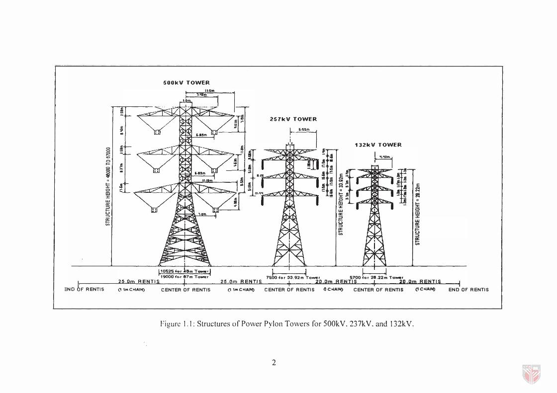
power pylon towers. The design, the construction of transmission lines and wood poles
for power line supports are done by Tenaga Nasional Berhad (TNB). The transmi�sion
lines are divided into three major categories : 500kV, 257kV, and 132kV, as shown in
Figure 1 . 1 . The End-Joint of a tower is constructed with a wooden cross-arm. For
commercial plantations (the private sector), wood poles are used as power line supports,
instead of the costly concrete or galvanized iron line supports now in use (Hus;;ein,
1 998).
The most popular uses of heavy hardwoods in this country are for J1.�avy
constructions such as wooden houses, railway sleepers, timber bridges, and power line
poles based on the woods' natural durability. By far Chengal is the most popular
hardwood fit for the above purposes.
� � ..
gl � r-oc 0
81 � .. a � "
�I ! :: w �
W Q: :::J I-U :::J Q: l-V>
25.0 :NO OF RENTIS (I 1 .... C 'lAI'!)
500kV TOWER
CENTER OF RENTIS (I 1 .... COlA!,!)
257kV TOWER
� I� I iii �
nl� 132kV TOWER
.. I �·�Im I .. .. I!
.. �
£t � .. .Ii � .Ii !! � �� � ....
M ... :!: .I � ! II !i:� . .... !!! � �
om � iIi
..- ---, 7500 40r 33.92m To_,
::J: w a:: � (.) :::J a: l-en
CENTER OF RENTIS 0 ColA!"'.)
.. - ...... 5700 40r 21J.22m To_.
CENTER OF RENTIS
Figure 1 . 1 : Structures of Power Pylon Towers for SOOkV. 237kV. and 132kV.
2
E .... <'"! � II
I-:J: C) iIi :J: W a:: :J I-U :J a:: t;
(I COlA!"'.) END OF RENTIS
The hot and humid climate in tropical countries like Malaysia facilitate� the
growth of fungi and other destructive microorganisms in wooden structures. Thereby,
deterioration of wooden structures occurs. It takes the forms of splits, cracks, and other
defects that permit the entry of fungi into the cores of the poles, rendering 1 hem
unsuitable for use as line supports. For wooden structures, this nature of degradation or
deterioration can inhibit the performance of the entire structure.
Hence. wooden cross-arms inspection and maintenance are essential f(lI the
following reasons:
i) Safety to life and property: wooden cross-arms should be maintained
above definite minimum strength requirements. The strength value of
each species of wood is different from others. The minimum strength
requirements according to species of wood have been choser, for
intelligent applications of woods.
ii) efficient service within the system: outages or service interruption due
to pole failures should be kept to a minimum. For examples,
mechanical damage may lead to a reduction in the useful lift· of a
wooden cross-arm, and maintenance works that leave some holes
after testing (quasi nondestructive method) the wooden quality
condition may also lead to degradation of wood.
i i i) economical operation: the number of wooden cross-arm replacements
should not be excessive and the maximum useful life shou ld be obtained from every wooden cross-arm.
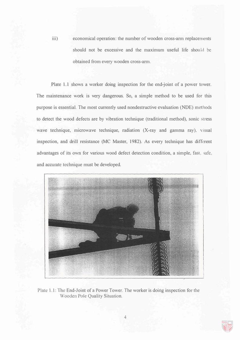
Plate 1 . 1 shows a worker doing inspection for the end-joint of a power tower.
The maintenance work is very dangerous. So, a simple method to be used for this
purpose is essential. The most currently used nondestructive evaluation (NDE) metl10ds
to detect the wood defects are by vibration technique (traditional method), sonic stress
wave technique, microwave technique, radiation (X-ray and gamma ray). visual
inspection, and dril l resistance (Me Master, 1 982). As every technique has different
advantages of its own for various wood defect detection condition, a simple, fast. safe, and accurate technique must be developed.
Plate 1 . 1 : The End-Joint of a Power Tower. The worker is doing inspection for the Wooden Po le Quality Situation.
4