universiti putra malaysia development …psasir.upm.edu.my/10737/1/fk_2001_3_a.pdfyang baik. walau...
TRANSCRIPT
UNIVERSITI PUTRA MALAYSIA
DEVELOPMENT OF LOW POWER CONVERTER SOLAR-BASE SYSTEM
MOHAMED AGRIBI FARHAT
FK 2001 3
DEVEL OPMENT OF L OW POWER CONVERTER SOL AR-B ASE SYSTEM
B y
MOHAMED AGRIB I FARHAT
Thesis Submitted in Fulfilment of Requirement for the Degree of Master of Science in the Faculty of Engineering
U niversiti Putra Malaysia
November 2001
Dedicated to
My
Parents, Brothers, Sisters, Wife and Daughter
11
Abstract of thesis presented to the Senate of Universiti Putra Malaysia in fulfilment of the requirement for the degree of Master of Science
DEVELOPMENT OF L OW POWER CONVERTER SOLAR-BASED SYSTEM
By
MOHAMED AGRmI FARHAT
November 2001
Chairman: Dr. Ishak B in Aris
Faculty: Engineering
With the recurrent oil crises and the new environmental boundary conditions for
energy production and use, the photovoltaic, PV, system development can be a very
promising strategic solution, which releases together with the photovoltaic energy cost
effectiveness goal, an actual clean, renewable, and alternative energy option. However,
the continues decline in photovoltaic module prices in the international market gives
more attention to design the supplementary equipment with low cost and high
reliability, such as battery charger and DC-to-AC inverter.
The objective of this project is study the effect of irradiation and temperature on
the output of solar module and to design, construct, and test battery charger and DC-to-
AC inverter for stand alone system. The proposed stand-alone system consists of 5
111
solar panels, a battery charger, a sealed lead acid battery, a DC-to-AC inverter, and AC
loads.
The solar energy has been converted to an electric energy usmg a panel of
photovoltaic cells. The electric energy stored in a sealed lead acid battery 30Ah, 12V.
The storage process was controlled by an electronic charger, which has been designed
and developed for this purpose.
A low cost, PWM inverter has been designed and constructed using power BJT
switches and electronic components that are common and cheap to convert the stored
DC energy to an AC one, and to provide the AC voltage for a small and medium AC
loads. Both charging and discharging of the stored energies have been examined, and
good results have been obtained.
Results of the experimental and simulation work showed that there was a good
agreement between the hardware and software. This indicated that the proposed stand
alone system was successfully developed.
IV
Abstrak tesis yang dikemukakan kepada senat Universiti Putra Malaysia sebagai memenuhi syarat keperluan untuk ijazah Master Sains
PEMBANGUNAN PENUKAR KUASA RENDAH BAGI PENGGUNAAN SISTEM BERASASKAN SOLAR
Oleh
MOHAMED AGRIBI FARHAT
November 2001
Pengerusi: Dr. Ishak Bin Aris
Fakulti: Kejuruteraan
Dengan berlakunya kekurangan minyak dan kondisi pembaharuan kuasa yang
terbatas, pengeluaran dan pembangunan untuk menggunakan photovoltaic sistem ialah
satu penyelesaian yang paling baik, yang mana boleh melepaskan secara bersama-
sarna dengan kuasa photo voltaic yang efektif, bersih, diperbaharni dan kuasa alternatif
yang baik. Walau bagaimanapun, kejatuhan harga modul fotovolta dalam pasaran
antarabangsa akan memberikan perhatian yang lebih untuk merekabentuk alatan
tambahan dengan kos yang rendah dan ketahanan yang tinggi, seperti pengecas bateri
dan penukar arus terns ke arus ulang alik.
Objektif penyelidikan ini ialah untuk mempelaj ari kesan penyinaran dan suhu
pada keluaran solar modul dan untuk merancang, membina pengecas bateri dan
penukar arus terns ke arus ulang alik untuk sistem yang berdiri sendiri. Sistem berdiri
v
sendiri ini terdiri dari 5 solar panel, pengecas bateri, bateri asid plumbum terkedap,
penukar. arus terus ke arus ulang alik, dan beban arus ulang-alik.
Kuasa solar telah diubah kepada kuasa elektrik dengan menguna panel sel fotovolta.
Kuasa elektrik disimpan di dalam , bateri asid plumbum terkedap 30 Ah, 12 V. Proses
penyimpanan ini dikawal dengan sebuah pengecas elektronik, yang sudah dirancang
dan dibina untuk tujuan ini.
PWM penukar telah dirancang dan dibina dengan menggunakan kuasa suis BJT dan
komponen-komponen elektronik yang dasar dan dengan kos rendah untuk merubah
penyimpan kuasa aruS terus kepada yang arus ulang alik, dan meyediakan voltan arus
ulang alik untuk beban-beban arus ulang alik yang kecil dan menengah.
Keputusan-keputusan dari hasil kajian dan kerja simulasi memperlihatkan hasil yang
bagus antara perkakasan dan perisian. Ini menunjukan sistem berdiri sendiri telah
berjaya dibina.
vi
ACKNOWLEDGEMENTS
I thank Allah (SWT), the most gracious and merciful, for giving me the
ability to finish this project successfully.
I would like at this juncture to express my deepest appreciation and gratitude
to my supervisor, Dr. Ishak bin Aris, for his encouragement and effective guidance
throughout the research period.
Special thanks and appreciation are extended to the members of my
supervisory committee, Dr. Sinan Mohamed Al-Bashi and Associate Professor Ir.
Dr. Norman Mariun, for their kind help and assistance.
Great thanks are also to my family for their unfailing support and
encouragement in this endeavour, especially my parents who never stopped praying
to Allah (SWT) for His guidance all the time.
Appreciation is also extended to the Faculty of Engineering for providing
the facilities and equipment necessary for undertaking this project.
Finally, I would like to thank all those who have in any way given me their
help, comments and suggestions.
VI
I certify that an Examination committee met on 5th November 200 1 to conduct the final examination of Mohamed Agribi Farhat on his Master of Science thesis entitled ''Development of Low Power Converter Solar-Base System" in accordance with Universiti Pertanian Malaysia (Higher Degree) Act 1 980 and Universiti Pertanian Malaysia (Higher Degree) Regulation 1 98 1 . The Committee recommends that the candidate be awarded the relevant degree. Members of the Examination Committee are as follows:
NASRULLAH KHAN, Ph.D. Lecturer Faculty of Engineering Universiti Putra Malaysia (Chairman)
ISHAK BIN ARIS, Ph.D. Lecturer Faculty of Engineering Universiti Putra Malaysia (Member)
NORMAN BIN MARIUN, ASSOC. PROF. Ph.D. Lecturer Faculty of Engineering Universiti Putra Malaysia (Member)
SINAN MAHMUD BASHI, Ph.D. Lecturer Faculty of Engineering Universiti Putra Malaysia (Member)
AINI IDERIS, Ph.D. Professor/ Dean of Graduate School Universiti Putra Malaysia
Date: � JAN 2002
VIll
This thesis submitted to the Senate of Universiti Putra Malaysia has been accepted as fulfilment of the requirements for the degree of master of Science.
AINI IDERIS, Ph.D. Professor/ Dean of Graduate School Universiti Putra Malaysia
Date: 1 4 MAR 2uU2
Vlll
DECLARA TION
I hereby declare that the thesis is based on my original work except for quotations and citations, which have been dully acknowledged. I declare that this thesis has not been previously or concurrently submitted for any other degree at UPM or any other institutions.
(MOHAMED AGRIBI FARHAT)
Date: December 1 1 , 200 1
x
TABLE OF CONTENTS
DEDICATION ABSTRACT ABSTRAK ACKNOW ALDMENTS APPROVAL DECLARATION LIST OF TABLES LIST OF FIGURES LIST OF PLATES LIST OF ABBREVIATIONS
CHAPTER I INTRODUCTION
n
Prologue Importance of the Project Objective of the Project Thesis Layout
LITERATURE REVIEW History of Photovoltaic Fossil Fuels Challenge of C02 Pollution Environmental Benefits of Renewable Energy Renewable Energy in Malaysia Why PV? Solar Energy Applications General Construction of the Photovoltaic System Solar Cells Factors Affecting the Electrical Characteristics Battery Battery Charger Basic Inverter Inverter Types Inverter Circuit Topologies BJTs Power Diode Summary
Xl
Page
11 111 V Vll Vlll X X111 XIV XVl XV11
1 1 2 3 4
5 5 6 7 8 9 1 0 10 1 2
24 26 26 27 28 30 35 39 41
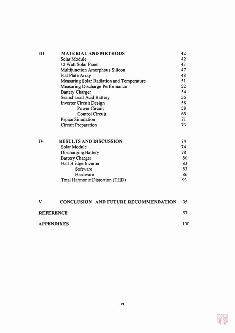
m MA TERIAL AND METHODS 42 Solar Module 42 12 Watt Solar Panel 43 Multijunction Amorphous Silicon 47 Flat Plate Array 48 Measuring Solar Radiation and Temperature 51 Measuring Discharge Performance 52 Battery Charger 54 Sealed Lead Acid Battery 56 Inverter Circuit Design 58
Power Circuit 58 Control Circuit 65
Pspice Simulation 71 Circuit Preparation 73
IV RESULTS AND DISCUSSION 74 Solar Module 74 Discharging Battery 78 Battery Charger 80 Half Bridge Inverter 83
Software 83 Hardware 86
Total Harmonic Distortion (THD) 93
V CONCLUSION AND FUTURE RECOMMENDA nON 95
REFERENCE 97
APPENDIXES 1 00
Xl
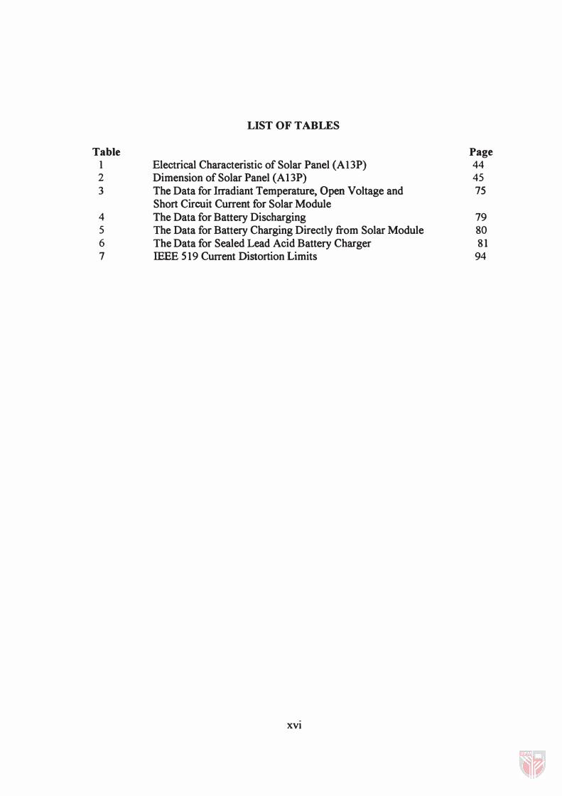
Table 1 2 3
4 5 6 7
LIST OF TABLES
Electrical Characteristic of Solar Panel (A13P) Dimension of Solar Panel (A13P) The Data for Irradiant Temperature, Open Voltage and Short Circuit Current for Solar Module The Data for Battery Discharging The Data for Battery Charging Directly from Solar Module The Data for Sealed Lead Acid Battery Charger IEEE 519 Current Distortion Limits
XVI
Page 44 45 75
79 80 81
94
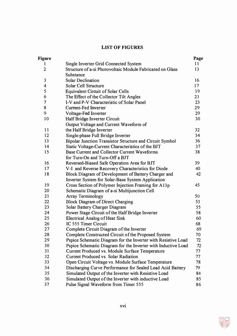
LIST OF FIGURES
Figure Page 1 Single Inverter Grid Connected System 1 1 2 Structure of a-si Photovoltaic Module Fabricated on Glass 1 3
Substance 3 Solar Declination 1 6 4 Solar Cell Structure 1 7 5 Equivalent Circuit of Solar Cells 1 9 6 The Effect of the Collector Tilt Angles 2 1 7 I-V and P-V Characteristic of Solar Panel 23 8 Current-Fed Inverter 29 9 Voltage-Fed Inverter 29 1 0 Half Bridge Inverter Circuit 30
Output Voltage and Current Waveform of 1 1 the Half Bridge Inverter 32 1 2 Single-phase Full Bridge Inverter 3 4 1 3 Bipolar Junction Transistor Structure and Circuit Symbol 36 1 4 Static Voltage-Current Characteristics of the BJT 37 1 5 Base Current and Collector Current Waveforms 38
for Tum-On and Tum-Off a .J3IT 1 6 Reversed-Biased Safe Operation Area for BJT 39 1 7 V -I and Reverse Recovery Characteristics for Diode 40 1 8 Block Diagram of Development of Battery Charger and 42
Inverter System for Solar-Base System Application 1 9 Cross Section of Polymer Injection Framing for A13p 45 20 Schematic Diagram of a-si Multijunction Cell 2 1 Array Terminology 50 22 Block Diagram of Direct Charging 53 23 Solar Battery Charger Diagram 55 24 Power Stage Circuit of the Half Bridge Inverter 58 25 Electrical Analog of Heat Sink 60 26 IC 555 Timer Circuit 68 27 Complete Circuit Diagram of the Inverter 69 28 Complete Constructed Circuit of the Proposed System 70 29 Pspice Schematic Diagram for the Inverter with Resistive Load 72 30 Pspice Schematic Diagram for the Inverter with Inductive Load 72 3 1 Current Produced vs. Module Surface Temperature 77 32 Current Produced vs. Solar Radiation 77 33 Open Circuit Voltage vs. Module Surface Temperature 78 34 Discharging Curve Performance for Sealed Lead Acid Battery 79 35 Simulated Output of the Inverter with Resistive Load 84 36 Simulated Output of the Inverter with inductive Load 85 37 Pulse Signal Waveform from Timer 555 86
XVi

38 39 40 4 1 42 43 44
Output Signal Waveform from Counter 1 Output Signal Waveform from Counter 2 Output Signal Waveform from Flip-Flop The Output of the Transformer without Load The Output of the Transformer with Lamp 7 .5 watt The Output of the Transformer with Lamp 1 5 watt The Output of the Transformer with Lamp 40 watt
XV)
87 87 88 89 90 9 1 92
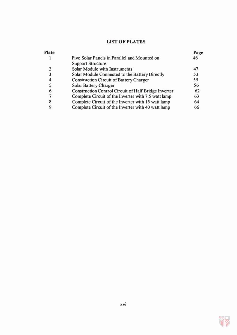
Plate 1
2 3 4 5 6 7 8 9
LIST OF PLATES
Five Solar Panels in Parallel and Mounted on Support Structure Solar Module with Instruments Solar Module Connected to the Battery Directly Construction Circuit of Battery Charger Solar Battery Charger Construction Control Circuit of Half Bridge Inverter Complete Circuit of the Inverter with 7 .5 watt lamp Complete Circuit of the Inverter with 1 5 watt lamp Complete Circuit of the Inverter with 40 watt lamp
XVI
Page 46
47 53 55 56 62 63 64 66
LIST OF ABBREVIATIONS
AC Alternate Current
Ah Ampere hour
ARC Anti-reflection Coating
a-Si Amorphous Silicon
BJT Bipolar Junction Transistor
C Capacitor
CSI Current Source Inverter
D Diode
DI Light Emitting Diode
f Frequency
FF Fill-Form
HZ Hertz
he Short Circuit Current
DC Direct Current
eV Electron Volt
KTOE Kilo Ton Oil Equivalent
L Inductance
Pc Power Loss
Ppm Parts per million
PV Photovoltaic
XVllI
PWM Pulse Width Modulation
Q Transistor
R Resistance
S Switch
S 1 Switch 1
S2 Switch 2
SOA Safe Operation Area
T Temperature
TIT Reverse Recovery Time
VIS Voltage Source Inverter
Voc Open Voltage Circuit
e Thermal Resistance
0 Solar Declination
XVlll
CHAPTER I
INTRODUCTION
Prologue
This thesis is in three parts. The first is a study of the photovoltaic (PV) system
and related topics, such as solar radiation and the solar cell. The photovoltaic effect is the
direct conversion of light energy into electricity by solar cells. Electricity is a high quality
energy, suitable for almost every type of application.
The second and main part is the design and construction of a charger for sealed
lead acid batteries. The charger comprises of two units - a power processor and battery
control. The power-processor is based on step-down DC-to-DC converter topology, while
the battery control is based on constant voltage mode control.
The third part is the design and construction of a DC-to-AC half bridge inverter -
a circuit to convert DC, or direct current, from a battery to AC, or alternating current, for
home applications, such as lighting and radio.
2
Importance of the Project
A PV system is a very attractive primary energy producer as its source of power -
the sun - is virtually inexhaustible, universally available and not subject to any business
or political monopoly. PV modules are solid-state devices that passively convert sunlight
to electricity. By adding modules, a PV system can be built to any size, and it is highly
reliable and requires little maintenance. Of all the energy sources, photoelectricity poses
the lowest environmental and safety risk.
Photoelectricity is more important in developing countries where much of the
population live in dispersed rural communities. Electrification of the areas is difficult
and costly and generally not economic for the small power loads required.
Malaysia lies in the centre of the tropics, just above the equator between latitudes
1 "20 N to 6°40/ N and longitudes 99°35/E to 1 0Y20 E. It possess the requisite
sunshine with which to exploit photoelectricity.
Another attraction about photoelectricity is that amorphous silicon absorbs
sunlight extremely well, so that only a very thin layer is required (about 1 Ilm as
compared with 1 00 Ilm or so for the crystalline cell), allowing considerable savings in the
silicon wafer used for the solar cell.

3
The battery charger provides constant voltage charging as the most efficient and
fastest way of charging sealed lead acid batteries. The charger must be simple in design
to minimize maintenance in the rural areas where it is likely to be used.
As the bulk of electricity used today is AC, the inverter is a very important
requisite in a PV system to convert DC from the storage battery to AC for use.
Objectives of the Project
This project has four objectives.
1 . Study of the PV module - the effect of sunlight intensity and cell temperature on
conversion efficiency. The study will encompass factors such as geographical
location, collector orientation throughout the day and atmospheric transparency.
2. Designing a battery charger for sealed lead acid batteries using solar energy.
3. Designing a DC-to-AC single phase half bridge inverter to convert DC to AC for
home use.
4. Simulating a DC-to-AC single phase inverter using Pspice software.
4
Thesis Layout
The thesis is divided into five chapters. Chapter 1 introduces the work and states
the objectives.
Chapter 2 reviews the literature on the environmental benefits of renewable
energy, solar radiation and the solar cell, battery charger and the general structure of a
DC-to-AC converter.
The work done, including designing, construction and testing separately each
component of the battery charger and inverter, and simulation of the DC-to-AC inverter,
is presented in Chapter 3.
The performance of the battery charger, inverter and simulation are discussed in
Chapter 4. Finally, Chapter 5 gives the conclusion and suggestions for future work.
CHAPTER II
LITERA TURE REVIEW
History of PV
The physical effect underlying photovoltaics (PV s) was first observed by
Becquerel (1839) when he produced a current by exposing silver electrodes to
radiation in an electrolyte. Adams and Day (1877) described the effect in more detail
later when they exposed selenium electrodes to radiation and produced a current.
In the 20th century, work by Lange (1930), Grondall (1933) and Schottky
(1930) on selenium and cuprous oxide cells led to the photographic exposure meter
and many other photo cell applications.
In 1954, Chapin and co-workers at Bell laboratories, USA developed the first
solar cell based on crystalline silicon with an efficiency of 6%. This efficiency was
increased to 10010 within a few years. The first viable use for solar cells was in
satellite power supply, and PV convincingly proved its worth in this application.
The main driving force for the widespread use of PV for terrestrial power
supply came in 1973 with the first oil crisis, and PV conversion has since become a
significant element in most renewable energy programmes.
6
Fossil Fuels and the Challenge of Carbon Dioxide Pollution
The combustion of fossil fuels releases CO2 to the atmosphere and this is
increasingly seen as one of the major causes of global warming. A 1000 MW coal
fired power plant emits 270 kg/second of C02. In pre-industrial times, the
atmospheric CO2 concentration was <290 parts per million (ppm) but by 2000 it was
377 ppm and by 2050 is expected to be double or triple the pre-industrial level. The
C02 concentration is expected to peak towards the end of the 21st century, by which
time most of the world's fossil fuels would have been consumed. Such a dramatic
increase in atmospheric CO2 concentration will almost certainly result in significant
warming of the earth (Danial et a!., 1983).
It is estimated that in 2025 the global CO2 emission will be 2.4 times that of
the present, but to stabilize the atmospheric concentration at the current level would
require a more than 60% reduction from the present emission. The developed
countries are the main villains with their 20 per cent of the world's population
emitting more than half the CO2 (Shuzo, 1993).
The earth receives an enormous amount of solar radiation daily. To maintain
its temperature, the planet must radiate off the equivalent energy. But radiation has a
wavelength inversely proportional to the fourth power of the temperature of its
source. Thus the very hot sun emits shortwave radiation, and the very much cooler
earth longwave radiation. C02 is transparent to shortwave radiation but absorbs the
long wavelengths, including that emitted by the earth, thus trapping the heat. The