universal panels & accessories · this manual was designed to improve your erection time and...
TRANSCRIPT

UniversalUniversalPanels &Panels &AccessoriesAccessoriesErection ProceduresErection Procedures
UniversalPanels &Accessories

Introduction . . . . . . . . . . . . . . . . . . . . . . . . . . . . . . . . . . . . . . . . . . . . . . . . . . . . .1
Definitions of Competent & Qualified Person . . . . . . . . . . . . . . . . . . . . . . . . . . .2
General Notes . . . . . . . . . . . . . . . . . . . . . . . . . . . . . . . . . . . . . . . . . . . . . . . . . . .3
Universal Stationary Scaffold . . . . . . . . . . . . . . . . . . . . . . . . . . . . . . . . . . . . . .4, 5
Typical Rolling Tower . . . . . . . . . . . . . . . . . . . . . . . . . . . . . . . . . . . . . . . . . . . . .6
High Rolling Tower . . . . . . . . . . . . . . . . . . . . . . . . . . . . . . . . . . . . . . . . . . . . . . .7
Putlogs & Proper Installation . . . . . . . . . . . . . . . . . . . . . . . . . . . . . . . . . . . . .8, 9
Scaffold Access Unit . . . . . . . . . . . . . . . . . . . . . . . . . . . . . . . . . . . . . . . . . . . . . .10
Scaffold Access-Alternate Construction . . . . . . . . . . . . . . . . . . . . . . . . . . . . . . .11
Typical Tank Layout . . . . . . . . . . . . . . . . . . . . . . . . . . . . . . . . . . . . . . . . . . . . . .12
Universal Scaffold “Ezebilt” . . . . . . . . . . . . . . . . . . . . . . . . . . . . . . . . . . . . . . . .13
Universal Scaffold “Unibilt” . . . . . . . . . . . . . . . . . . . . . . . . . . . . . . . . . . . . . . . .14
Scaffold Inspection Procedures . . . . . . . . . . . . . . . . . . . . . . . . . . . . . . . . . . . . . .15
Scaffold Industry Association (Code of Safe Practices) . . . . . . . . . . . . . . . . .16, 17
INTRODUCTIONUse common sense when working with Scaffold
Your Safety is our #1 Concern
Universal Scaffolds are designed with your safety in mind every step of the way. They are theproducts of input from you, the actual end user, and Universal Manufacturing Corp., a leaderin safe access equipment for over 70 years. It is in the best interest of the ConstructionIndustry as a whole to maintain SAFE and therefore, productive job sites.
This Manual was designed to improve your erection time and performance of your worksiteby providing information on general erection and maintenance guidelines. Consult your scaf-fold supplier or Universal if you are unsure of anything or if you require additional informa-tion. Universal Manufacturing Corp. offers Engineering Services to their customers, whichincludes load information, AutoCAD Drawings, special product design and information onall OSHA requirements.
CONTENTS
1

2
A QUALIFIED PERSON
Means one who, by possession of a recognized degree, certificate, or professional
standing, or who by extensive knowledge, training, and experience, has successfully
demonstrated his/her ability to solve or resolve problems related to the subject mat-
ter, the work, or the project.
COMPETENT PERSON
Must have had specific training in and be knowledgeable about the structural integri-
ty of scaffolds and the degree of maintenance needed to maintain them. The compe-
tent person must also be able to evaluate the effects of occurrences such as a dropped
load, or a truck backing into a support leg that could damage a scaffold. In addition,
the competent person must be knowledgeable about the requirements of this stan-
dard. A competent person must have training or knowledge in these areas in order to
identify and correct hazards encountered in scaffold work.
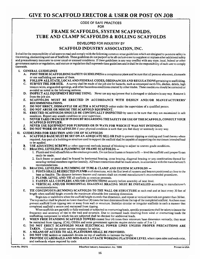
GENERAL NOTES
1) Please remember it is DANGEROUS AND ILLEGAL to erect any Scaffold System without proper Guardrail, Midrailand Toeboard Components.
2) Mixing components of other Scaffold such as Frames, Braces, Guardrail, etc. is considered improper use of Scaffoldwhich creates a dangerous work site.
3) Since field conditions vary and are beyond the control of Universal Scaffolds, safe and proper erection and use of scaf-folding is the sole responsibility of the user.
4) Metal tubular frame scaffold including all accessories such as Braces, Brackets, Putlogs. Adjustable Bases, Ladders,etc...are designed per Universal Manufacturing Corp. and OSHA requirements.
5) Periodic inspections shall be made on all welded frames and associated components. The manufacturer shall authorizeany modifications or repairs.
6) No scaffold shall be erected, moved, dismantled or altered except under the supervision of competent personnel.(OSHA Code of Federal Regulations 1995 (a) (3) p. 356).
7) The footing or anchorage for Scaffolds shall be sound, rigid and capable of carrying the maximum intended load with-out settling or displacement. Unstable objects such as barrels, boxes, loose brick or concrete blocks shall not be used tosupport scaffolds or plank.
8) Clamp-on Ladders will extend at least 3 feet beyond the designated platform for safe access and egress.
9) All plank will be Scaffold Grade, or equivalent, as recognized by approved grading rules for the species of wood used.The maximum permissible spans for 2x10 inch or wider planks shall be as shown in the following:
Full thickness Nominal thicknessUndressed LumberLumber
Working load (p.s.f.) 25 50 75 25 50Permissible span (ft.) 10 8 6 8 6(OSHA Code of Federal Regulations 1995, (a) (10) p. 357)
10) Sill plates (typically 2x10 scaffold plank) are required at the base of all stationary scaffolds to aid in uniform weight dis-tribution and protect ground level surfaces.
11) OSHA requires a registered Professional Engineer to design all scaffolds over 125 feet in height.
Please remember it is DANGEROUS and ILLEGAL to erect any scaffold System without proper Guardrails, Midrailsand toeboard. The system will conform to all government regulations now and in the future when properly erected withsafety guidelines posted. Mixing components of other Scaffold such as Frames, Braces, Guardrail, etc. is consideredimproper use of scaffold which creates a dangerous work site. The OSHA requirements found in this manual will helpyou to provide a safe working condition for everybody.
3
UNIVERSAL STATIONARY SCAFFOLDING
4
Guardrail, entrance gates and toeboards shall beinstalled on all open sides and ends of platformsmore than 10 feet above the ground or floor. Entrancegates should be erected so that they swing inwardtoward deck to open.
Guardrails should be 2” x 4” or theequivalent strength, installed no lessthan 38” or not more than 45” high,with a Midrail, when required, or 1” x 4”lumber or equivalent strength. AllGuardrail shall be capable of supportinga 200 Lb. Load. Supports should be atintervals not to exceed 10 feet.Toeboards shall be a minimum of 4” inheight above deck.
Scaffold planking shall extend overtheir end supports not less than 6”nor more than 18”.
To prevent movement, the scaffold shallbe secured to the building or structureat intervals not exceeding 30 feethorizontally nor 26 feet vertically.
Scaffold shall be secured to permanentstructure through use of anchor bolts orother equivalent means.
Scaffold legs shall be set on Adjustable Bases orPlain Bases placed on mud sills or otherfoundations that are adequate to support themaximum intended load.
SR-77’ Side Guardrail
SP-3XGuard Post
EGA-EAXEnd GateAssembly
IGAIntermediate
Gate Assembly
U-SAU Clamp-OnType Ladder
U-SAUBLadderBracket
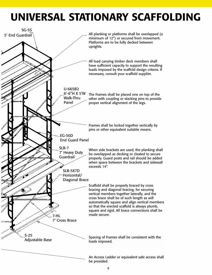
5
All planking or platforms shall be overlapped (aminimum of 12”) or secured from movement.Platforms are to be fully decked betweenuprights.
SG-5S5’ End Guardrail
EG-50DEnd Guard Panel
SLB-77’ Heavy DutyGuardrail
SLB-5X7DHorizontal/Diagonal Brace
7-HL7’ Cross Brace
All load carrying timber deck members shallhave sufficient capacity to support the resultingloads imposed by the scaffold design criteria. Ifnecessary, consult your scaffold supplier.
The Frames shall be placed one on top of theother with coupling or stacking pins to provideproper vertical alignment of the legs.
Frames shall be locked together vertically bypins or other equivalent suitable means.
When side brackets are used, the planking shallbe overlapped as decking or cleated to secureproperly. Guard posts and rail should be addedwhen space between the brackets and sidewallexceeds 14”.
Scaffold shall be properly braced by crossbracing and diagonal bracing, for securingvertical members together laterally, and thecross brace shall be of such length as willautomatically square and align vertical membersso that the erected scaffold is always plumb,square and rigid. All brace connections shall bemade secure.
Spacing of Frames shall be consistent with theloads imposed.
An Access Ladder or equivalent safe access shallbe provided.
U-665B26’-6”H X 5’WWalk-ThruPanel
S-25Adjustable Base
UNIVERSAL STATIONARY SCAFFOLDING
6
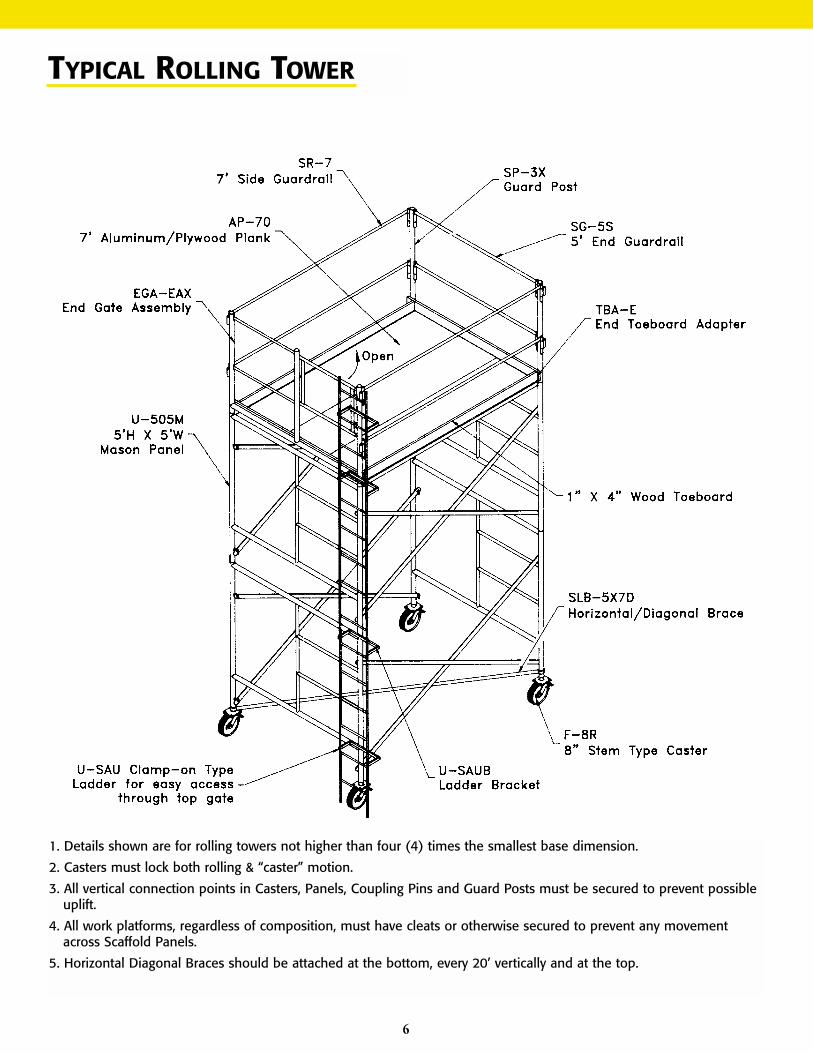
TYPICAL ROLLING TOWER
1. Details shown are for rolling towers not higher than four (4) times the smallest base dimension.
2. Casters must lock both rolling & “caster” motion.
3. All vertical connection points in Casters, Panels, Coupling Pins and Guard Posts must be secured to prevent possibleuplift.
4. All work platforms, regardless of composition, must have cleats or otherwise secured to prevent any movementacross Scaffold Panels.
5. Horizontal Diagonal Braces should be attached at the bottom, every 20’ vertically and at the top.
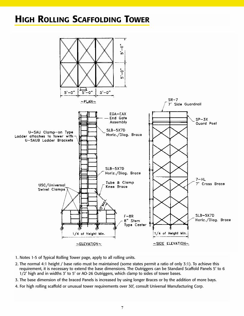
HIGH ROLLING SCAFFOLDING TOWER
1. Notes 1-5 of Typical Rolling Tower page, apply to all rolling units.
2. The normal 4:1 height / base ratio must be maintained (some states permit a ratio of only 3:1). To achieve thisrequirement, it is necessary to extend the base dimensions. The Outriggers can be Standard Scaffold Panels 5’ to 61/2’ high and in widths 3’ to 5’ or AO-26 Outriggers, which clamp to sides of tower bases.
3. The base dimension of the braced Panels is increased by using longer Braces or by the addition of more bays.
4. For high rolling scaffold or unusual tower requirements over 30’, consult Universal Manufacturing Corp.
7
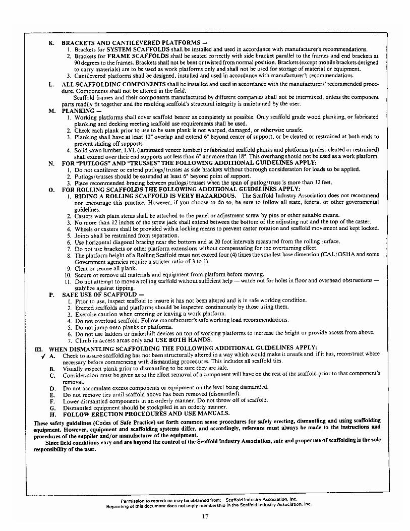
8
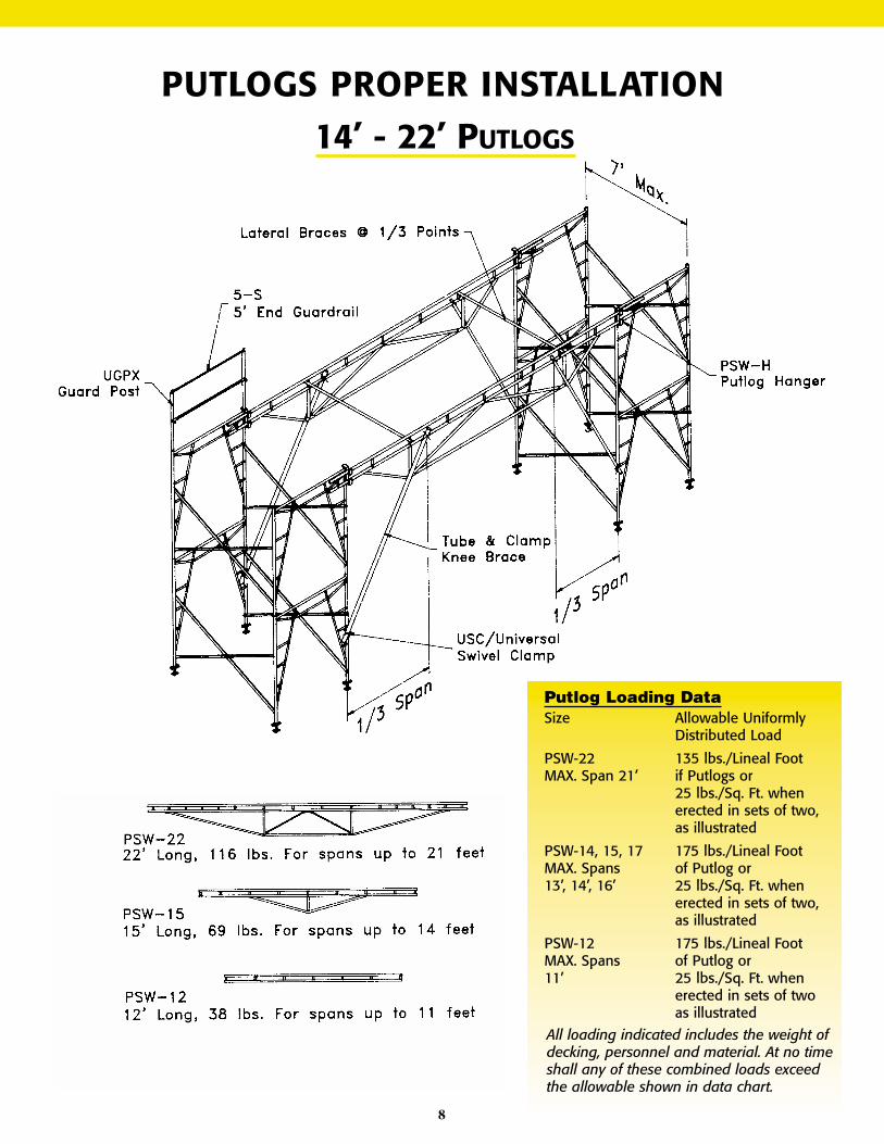
14’ - 22’ PUTLOGS
Putlog Loading DataSize Allowable Uniformly
Distributed Load
PSW-22 135 lbs./Lineal FootMAX. Span 21’ if Putlogs or
25 lbs./Sq. Ft. whenerected in sets of two,as illustrated
PSW-14, 15, 17 175 lbs./Lineal FootMAX. Spans of Putlog or13’, 14’, 16’ 25 lbs./Sq. Ft. when
erected in sets of two,as illustrated
PSW-12 175 lbs./Lineal FootMAX. Spans of Putlog or11’ 25 lbs./Sq. Ft. when
erected in sets of twoas illustrated
All loading indicated includes the weight ofdecking, personnel and material. At no timeshall any of these combined loads exceedthe allowable shown in data chart.
PUTLOGS PROPER INSTALLATION
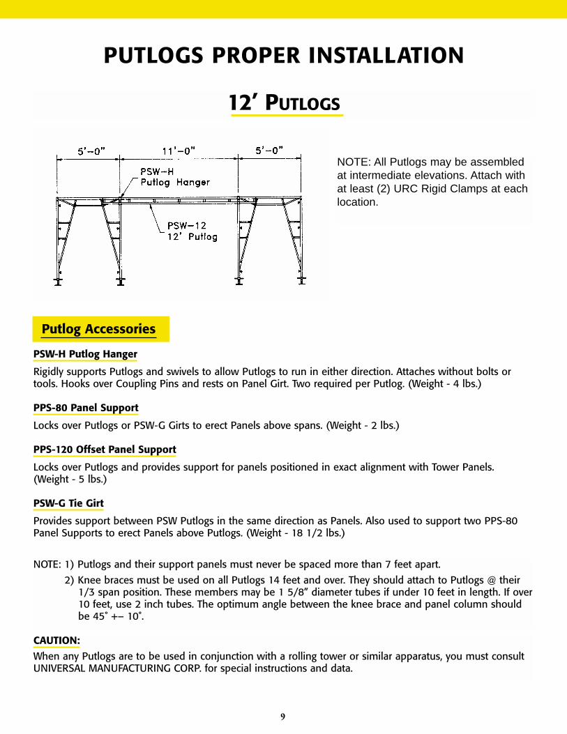
12’ PUTLOGS
NOTE: All Putlogs may be assembledat intermediate elevations. Attach withat least (2) URC Rigid Clamps at eachlocation.
Putlog Accessories
PSW-H Putlog Hanger
Rigidly supports Putlogs and swivels to allow Putlogs to run in either direction. Attaches without bolts ortools. Hooks over Coupling Pins and rests on Panel Girt. Two required per Putlog. (Weight - 4 lbs.)
PPS-80 Panel Support
Locks over Putlogs or PSW-G Girts to erect Panels above spans. (Weight - 2 lbs.)
PPS-120 Offset Panel Support
Locks over Putlogs and provides support for panels positioned in exact alignment with Tower Panels.(Weight - 5 lbs.)
PSW-G Tie Girt
Provides support between PSW Putlogs in the same direction as Panels. Also used to support two PPS-80Panel Supports to erect Panels above Putlogs. (Weight - 18 1/2 lbs.)
NOTE: 1) Putlogs and their support panels must never be spaced more than 7 feet apart.
2) Knee braces must be used on all Putlogs 14 feet and over. They should attach to Putlogs @ their1/3 span position. These members may be 1 5/8” diameter tubes if under 10 feet in length. If over10 feet, use 2 inch tubes. The optimum angle between the knee brace and panel column shouldbe 45˚ +– 10˚.
CAUTION:
When any Putlogs are to be used in conjunction with a rolling tower or similar apparatus, you must consultUNIVERSAL MANUFACTURING CORP. for special instructions and data.
9
PUTLOGS PROPER INSTALLATION
10
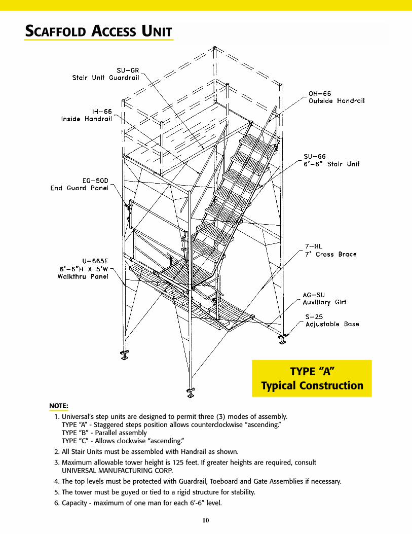
SCAFFOLD ACCESS UNIT
NOTE:
1. Universal’s step units are designed to permit three (3) modes of assembly.TYPE “A” - Staggered steps position allows counterclockwise “ascending.”TYPE “B” - Parallel assemblyTYPE “C” - Allows clockwise “ascending.”
2. All Stair Units must be assembled with Handrail as shown.
3. Maximum allowable tower height is 125 feet. If greater heights are required, consultUNIVERSAL MANUFACTURING CORP.
4. The top levels must be protected with Guardrail, Toeboard and Gate Assemblies if necessary.
5. The tower must be guyed or tied to a rigid structure for stability.
6. Capacity - maximum of one man for each 6’-6” level.
TYPE “A”Typical Construction
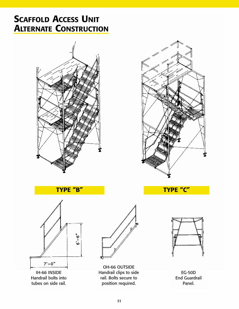
SCAFFOLD ACCESS UNITALTERNATE CONSTRUCTION
TYPE “B” TYPE “C”
IH-66 INSIDEHandrail bolts intotubes on side rail.
OH-66 OUTSIDEHandrail clips to siderail. Bolts secure toposition required.
EG-50DEnd Guardrail
Panel.
11
12
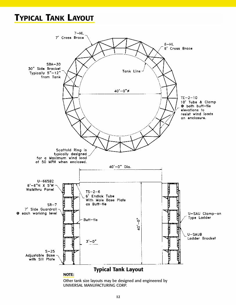
TYPICAL TANK LAYOUT
Typical Tank LayoutNOTE:
Other tank size layouts may be designed and engineered byUNIVERSAL MANUFACTURING CORP.
UNIVERSAL SCAFFOLD
The scaffold erection, safety instruction and illustration outlined within thismanual apply totally to both of UNIVERSAL’S standard types of Scaffold. All ofthe associated equipment and accessories can be used with either EZEBILT orUNIBILT Scaffold. The major difference between this equipment is the type ofside braces and locking systems.
Details as follows:
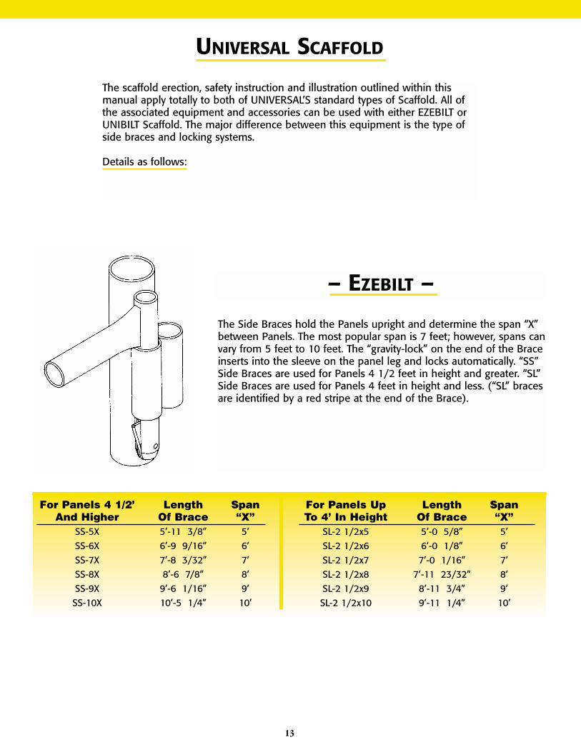
– EZEBILT –
The Side Braces hold the Panels upright and determine the span “X”between Panels. The most popular span is 7 feet; however, spans canvary from 5 feet to 10 feet. The “gravity-lock” on the end of the Braceinserts into the sleeve on the panel leg and locks automatically. “SS”Side Braces are used for Panels 4 1/2 feet in height and greater. “SL”Side Braces are used for Panels 4 feet in height and less. (“SL” bracesare identified by a red stripe at the end of the Brace).
For Panels 4 1/2’ Length SpanAnd Higher Of Brace “X”
SS-5X 5’-11 3/8” 5’SS-6X 6’-9 9/16” 6’SS-7X 7’-8 3/32” 7’SS-8X 8’-6 7/8” 8’SS-9X 9’-6 1/16” 9’SS-10X 10’-5 1/4” 10’
For Panels Up Length SpanTo 4’ In Height Of Brace “X”
SL-2 1/2x5 5’-0 5/8” 5’SL-2 1/2x6 6’-0 1/8” 6’SL-2 1/2x7 7’-0 1/16” 7’SL-2 1/2x8 7’-11 23/32” 8’SL-2 1/2x9 8’-11 3/4” 9’SL-2 1/2x10 9’-11 1/4” 10’
13

14
UNIBILT
Braces for UNIBILT are fastened securely to thePanel by the use of UNIVERSAL’S exclusive “BRACELOCK” which allows fast, easy assembly of scaffoldunits.
With lock bar in the horizontal position, the Bracesslip easily on the “BRACE LOCK”, and with fingerpressure, the lock bar moves into the vertical posi-tion which locks the Braces to the Panel untilreleased manually.
The Cross Braces for UNIBILT are structural steelangles. The Braces have 9/16” diameter holes inthe ends to slip over the brace locks on the Panelsand are riveted together at the center with 3/8”rivets to form a complete “X”. The “HL” - type CrossBrace is used with 305, 405, 465, 505 and 665Panels and are available in the following sizes:
NOTE:These Angle-Type Braces are also available inpre-galvanized tubular steel up to the 8-HL size.
Cat. No. “A” “B” Weight4-HL 4’-0” 5’-5” 11.35-HL 5’-0” 6’-3” 13.16-HL 6’-0” 7’-1” 14.67-HL 7’-0” 7’-11” 16.48-HL 8’-0” 8’-10” 18.39-HL 9’-0” 9’-9” 20.1
10-HL 10’-0” 10’-9” 22.0
SCAFFOLD INSPECTION PROCEDURES
Universal Manufacturing Corp. recommends the following inspection procedure as a general guideline for the assessment ofconstructed scaffolds. This procedure is not to be used as a substitute for training, experience and knowledge. All scaffolds, bylaw must be constructed under the supervision of a competent person, a person who can identify hazards and has the author-ity to eliminate the hazards.
• Familiarize yourself with all applicable codes, standards and regulations, including company rules.
• Inspect the overall jobsite for organization, housekeeping, coordination of workers, safety equipment and safetyprocedures.
• Observe the erection crew for procedure, fall protection, coordination and organization.
• Observe the overall scaffold. Does it appear to be constructed properly?
• Is the scaffold plumb?
• Is the scaffold level?
• Are Guardrail Systems installed on all open platforms?
• Is the top guardrail between 38-45 inches from the work surface?
• If there is no Guardrail System, are occupants wearing proper fall arrest equipment?
• Is falling object protection provided where required?
• Is the scaffold tied to the structure, and is the spacing per this manual’s requirements?
• Inspect the foundation. Are there sills?
• If Screw Jacks are used, are the handles tight?
• Are there Base Plates?
• Is there full contact between the Base Plates and the sills and/or foundations?
• Is there any evidence of settlement?
• Is there any evidence of wet soil or erosion?
• Is there access?
• How high is the first step? (It should be less than 24 inches)
• If a ladder is used, is there a rest platform at 35 feet or less?
• Does the ladder extend above the top platform or is there a handhold?
• Is there proper access between the ladder and the platform?
• If a stairway is used, are the handrails and guardrails installed?
• How do the platforms look?
• Are all platforms at least 18 inches wide?
• Is the space between the platform and the work surface less than 14 inches?
• What is the maximum spacing between plank? (It should be less 1 inch)
• Is there proper support for the plank?
• Are cantilevers minimized and within the regulations?
• If side brackets or outriggers are used, are they properly installed?
• Are all scaffold components in good condition?
• Are the materials loaded on the scaffold safely supported?
15
16
17