universal flow monitors - gilson eng manuals/universal flow...genman-200.5 2/03 2 a c b d e the...
TRANSCRIPT

1 GENMAN-200.5 2/03
UNIVERSAL FLOW MONITORS INC.1755 E. Nine Mile Road
Hazel Park, MI 48030-0249Ph. 248-542-9635 / Fax 248-398-4274
Email: [email protected]
Flow Monitor Installation and
Maintenance Instructions
for Vane and Piston Style
Variable Area Flow Monitors
U N I V E R S A L
FLOW MONITORSFLOW MONITORS
R
See our Website for a copy of the Warranty Statement at www.universalflow.com
or give us a call at 248/542-9635 to have one sent.

2GENMAN-200.5 2/03
ABC D
E
The following manual includes the installation and maintenance instructions for flow meters manufactured by Universal FlowMonitors Inc. All flow monitors are individually calibrated for use with a specific fluid requested in the order entry process.Different fluids should not be used without first consulting the factory to verify compatibility of materials and flow parameters,such as viscosity and specific gravity for liquids, or operating pressure, temperature and specific gravity for gases, of the newapplication. Meter designs are of the variable-area type and operate with a relatively low, pressure drop. The flow elementsare either a swinging vane or a repositioning piston.
B
C
D
F
E
A
Installation and Instruction Manual for Universal Flow Monitors, Inc. Flow Monitors
How the swinging-vane design works
Fluid enters at A, passes around the semi-circular vaneB, exits at outlet C. The vane resists the flow becauseof the spring D. The further the vane is pushed thelarger the passageway E becomes. This minimizes theincrease in pressure drop. The vane shaft turns tooperate the pointer F and remote signal devices such asthe switch G. The shaft can also turn switch cams andtransducers to actuate any remote readout devicespresent.
How the piston design works
Fluid flow causes a spring-loaded piston A having acircular opening at its center B to move along the axis ofa precision-tapered shaft C. This creates a variableorifice in direct proportion to the flow rate. The equilib-rium position of the piston is mechanically linked to thereadout pointer D, and the strong force developed asfluid pressure acts on a large piston area that easilyactuates the readout device E. Pressure drop increasesover rated flow range, averaging 3 PSI.
INDEXHow Vane and Piston Flow Meters work............2
Special Use Meters.............................................3
Construction Materials and Engineering Data.....4
Readout Specifications........................................5-8
Periodic Maintenance........................................10
Calibration Notes...............................................11
Dimension Information.....................................12-16
Replacement Parts Kits...................................17-33
Return Authorization Information..................34-37

3 GENMAN-200.5 2/03
Universal Flow Monitors has several special use flow meters for specific applications such as air, lube and water. Thesemeters are constructed of materials that are known to be compatible with the particular service intended. To select a seal,gasket, cover, readout, or dial assembly kit for any of these models requires conversion of the model prefix to that of astandard line meter. Additionally, accurate conversion of your specific use meter requires identification of size and sealmaterials. Use the following tables to select your correct standard model prefix, housing size and seal material:
Special Use Meters
MODEL PREFIX:
AS (svh) -use- SN-ESF
AM (mvh) -use- MN-ESF
AL (lvh) -use- LN-ESF
O (svh) -use- SN-ASB
O (mvh) -use- MN-ASB
OK (svh) -use- SN-BSF
OK (mvh) -use- MN-BSF
OO (ph) -use- LL-ABPSB
WB (svh) -use- SN-BSE
WB (mvh) -use- MN-BSE
WB (lvh) -use- LN-FSE
WP (ph) -use- LL-BBPSE
WVS (svh) -use- SN-BSE
WVM (mvh) -use- MN-BSE
WVL (lvh) -use- LN-FSE
WW (ph) -use- LL-BBPSE
WW (svh) -use- SN-BSE
WW (mvh) -use- MN-BSE
WW (lvh) -use- LN-FSE
Others consult factory
(ph=piston housing, svh=small vane housing,mvh=medium vane housing, lvh=large vane housing).
Note: Other manuals are available for Vortex,Sensor Manifold, FlowStream, Mensah, Octopus,
Insite and Transmitter

4GENMAN-200.5 2/03
HOUSINGS SN SM SH SX MN MM MH MX ML LN LE XHF LL** LP** LH**
HOUSING MATERIAL and WEIGHT (lb) †
Aluminum 4 4 9 9 654-in 706-in 78
8-in 1004 4
Aluminum/Nylon Bowl 3 7 7
Aluminum/Hard Coat 4 4 9 9
Brass 6 6 16 16 135 10
Aluminum Bronze4-in 2006-in 2208-in 260
Brass/Nylon Bowl 5 13 13
Cast Iron 6 6 7 19 19 30 120 10 10
Cast Iron/Nylon Bowl 5 13
Cast Iron/Nickel Plated/Teflon Impregnated
6 6 7 19 19 30 120 10 10
Carbon Steel 6 6 7 21 21 30 120 1204-in 2006-in 2208-in 260
12 12 14
Carbon Steel/Nickel Plated 7 30 120
Naval Bronze 6 6 16 16 135
Naval Bronze/Nylon Bowl 5 13
Polypropylene 12
Polysulphone 1.75 6
PVC 1.75 6 12
Teflon 12
Tefzel 1.75 6
316 Stainless Steel 6 6 7 21 21 30 120 1204-in 2006-in 2208-in 260
12 12 14
MAXIMUM FLUID TEMPERATURE (°F)
200 (Optional 300 & 400 °F) • • • • • • • • • • • •
100 for PVC and PP, 200 for Others • • •
MAXIMUM OPERATING PRESSURE LIQUIDS/GASES (PSIG)
300/125 (PSIG) • • • •
500/125 •
500/200 • •
1000/167 •
1500/375 •
2000/500 Iron & Steel • •
2000/500, 1200/450 Stainless Steel • •
*100 PVC, 150 Tefzel, 200 Polysulphone •
*100 PVC, 200 Tefzel & Polysulphone •
*100, 50 Teflon •
150 Plastic, 300 Metal Cap/125 Metal Cap •
Prior to installation always double check the system pressure, temperature, wetted parts’ compatibility, electricalratings, and all other requirements to verify that the flow meter supplied is appropriate for the application.
Construction Materials and Engineering Data
* Liquids only†Add 2 pounds for control boxes other than A.**Piston and cap material. Polysulfone plastic cap can be used in LL units up to 150 PSI (liquid), metal cap (same as housing) is used for all other units.
InstallationThese are in-line devices that can be mounted in any position without affecting performance. First, attach the meter at theport marked “in” by the appropriate means (threaded or flanged) ensuring the flow goes into that port. When threadingpipe into a cast iron meter, do not use teflon tape to seal the pipe threads . Then connect the meter at the “out” port.The installation diagrams on pages 10-13 give the critical mounting dimensions. To insure maximum accuracy, installcontrol valves downstream of the flow meter. If this is a gas application, back pressure must be maintained on the meterequal to the calibrated pressure. Units may have visual indication of flow only, or use a variety of switches,potentiometers, transmitters, or pneumatic switches.
*

5 GENMAN-200.5 2/03
Switch Specifications
Option(SYMBOL)
1,2 3,4 61,62 53,54 7, 7C*, 18 17, 17C*, 19 30,31
Rated By
Rating
Use
Deadband(Not to exceed)
UL/CSA/CE
15A-125,250, or480 VAC
2A-600 VAC1/2A-125 VDC,1/4A-250 VDC
1/8 HP-125 VAC,1/4 HP-250 VAC6A Resistive &5A Inductive-24 or 48 VDC
15A-125,250, or480 VAC
2A-600 VAC,1/2A-125 VDC1/4A-250 VDC,
1/8 HP-125 VAC1/4 HP-250 VAC,
6A Res. & 5A Ind.-24 or 48 VAC VDC
5A res., 3A ind.,115 VAC,
400 Hz28 VDC
11A, 1/4 hp,125/250 VAC;
5A res., 28 VDC;0.5A res.,125 VDC
11A, 1/4 hp,125/250 VAC;
5A res., 28 VDC;0.5A res.,125 VDC
0.5A,20-250
VAC/VDC
15A-125,250, or480 VAC
1A-125 VDC,1/2A-250 VDC
1/4 HP-125 VAC,1/2 HP-250 VAC3A Resistive &2.5A Inductive-
48 VDC24 VDC=
6A Res. & 5A Ind.
7% 1
7% 27% 1
7% 27% 1
7% 27% 1
7% 215% 1
25% 215% 1
25% 210% 1
15% 2
UL/CSA(CE Pending)
UL/CSA(CE Pending) MIL-S-8805
UL/CSA/*CENELEC
UL/CSA/*CENELEC UL/CSA
Switch TypeSPDT3-Wire
SPDT4-Wire
GeneralPurpose
1B,2B
UL/CSA/CE
15A-125,250, or480 VAC
2A-600 VAC1/2A-125 VDC,1/4A-250 VDC
1/8 HP-125 VAC,1/4 HP-250 VAC6A Resistive &5A Inductive-24 or 48 VDC
7% 1
7% 2
High-VibrationSPDT3-Wire
GeneralPurpose
GeneralPurpose
GeneralPurpose
High-Temperature
General and Corrosive Use
HazardousLocation
HazardousLocation
HazardousLocation
SPDT3-Wire
DPDT3-Wire
SPSTProximity
High-TempSPDT3-Wire
71,72
15A-125,250, or480 VAC
2A-600 VAC,1/2A-125 VDC1/4A-250 VDC,
1/8 HP-125 VAC1/4 HP-250 VAC,
6A Res. & 5A Ind.-24 or 48 VAC VDC
7% 1
7% 2
UL/CSA(CE Pending)
Gold-ContactSPDT3-Wire
Hermetically-Sealed SPDT
3-Wire
1Flow rates ≥15 GPM/56 LPM with exception of piston style. 2Flow rates ≤14 GPM/52 LPM including piston style.
The above chart shows each switch pictorially, details it by option number and switch type,and describes its rating and the rating agency, its use and deadband.
3-POSITION CONNECTOR (PC3)For 4-20 mA loopGRN/1-GRDRED/2-NEGRED/3-POS
5-POSITION CONNECTOR (PC-5)For a 3-wire For a 4-wireswitch switch (DC)RED/1-COM BLU/1-NC1RED/2-N.C. BLU/2-NO1GRN/3-GRD GRN/3-GRDRED/4-N.O. BLU/4-NO2RED/5-N/U BLU/5-NC2
For a 4-wire switch (AC)RED/1-NC1 GRN/3-GRDRED/2-NO1 RED/4-NO2GRN/3-GRD RED/5-NC2
6-POSITION CONNECTOR (PC6)For a two 3-wire switchesORN/1-NO1 WHT/4-NO2BLU/2-NC1 RED/5-NC2BLK/3-COM1 GRN/6-COM2
8-POSITION CONNECTOR (PC8)For a two 4-wire switchesORN/1-NC1 (1) WHT/5-NC1 (2)BLU/2-NC2 (1) RED/6-NC2 (2)WHT-BLK/3NO1 (1) GRN/7-NO1 (2)BLK/4-NO2 (1) RED-BLK/8-NO2 (2)
4-POSITION CONNECTOR (PC4)For a 3-wire switchBLK/1-N.O.WHT/2-N.C.RED/3-COMGRN/4-GRD
PIN IDENTIFICATION FOR B-H TYPE CONNECTORS

Setting Single Electrical Switches
Usually the switches are set at the factory as indicated in the model code on the nameplate, or as indicated on anattached paper tag. To reset the switch point for common switch options 1, 1B, 3, 11, 53, 61, and 71, proceed as follows.
Warning: Shut off the electric power to the control box before opening it.
1. Remove the nameplate, window, and gasket from the control box.
2. The cam that actuates the switch is located just under the pointer. The position of the cam dictates the flow rate atwhich the cam will trip the switch.
3. Turn the pointer so that it points at the desired flow rate on the scale. Against low spring forces you can do this bygrasping the pointer itself (and holding it in position while you adjust the cam).
NOTE: Some flow meters with higher spring forces (medium, large, and extra large vane style) have an extended shaftwhich provides a means of manually moving the vane and simulating flow. A wrench (supplied with those units) is used toturn an extension of the shaft located at the back of the unit, opposite from the control box.
Flow meters with very high spring force and no extended shaft (typically MN, MM, MH, series) can be handled by *remov-ing the bowl (under the housing).
WARNING: Isolate meter from process and be sure to bleed off any remaining pressure, as well as purge the lineof any hazardous chemical prior to removing the bowl.
To maintain factory calibration accuracy, mark the bowl mounting orientation and replace the bowl in the same positionafter the cam is properly adjusted. The vane is then grasped and turned. To get the edge of the vane out of its recessedseat, use a socket head screw wrench as a lever, inserting it into one of the vane set screws to rotate the vane. Toproperly set the cam, the set point must be approached from the normal flow condition. I.E., a low flow contact is set fordecreasing flow by moving the indicator above the low flow set point and adjusting the cam to activate or deactivate theswitch just as it arrives at the low flow setting. To set the cam for an increasing set point, the cam is adjusted to activate/deactivate the switch as it approaches the set point from zero.
4. While holding the pointer/shaft/vane in the desired position, depress the cam ring fully (approx. 1/16 inch) and rotate ituntil the switch actuates (clicks). Release your downward pressure and the cam ring will lock at that position.
5. If you can’t hear the switch click, you can determine contact closure with an ohmmeter connected across the switchterminals. Connect to the common and normally open or normally close on the switch.
6. To check the setting, direct the pointer again to the desired flow rate, noting where the switch actuates. Make adjust-ments as necessary. If the bowl was removed please place on guide roll pins and firmly tighten, in a X motion.
7. It’s much easier to set the switch point if you can do it with actual flow present. Adjust the flow to the desired pointwhere you want a signal to occur and turn the cam to actuate the switch as outlined above.
8. Replace window, nameplate, and gasket before turning on electric power.
U N I V E R S A L
FLOW MONITORSFLOW MONITORS
Exploded ViewSingle switch assembly
6
Switch
Dial Allen Screws
Cam Ring
Pointer
Cam Retainer
DO NOT LOOSEN DIAL
SCREW!!
Name Plate
Window
Gasket
Scale
Control Box
Spring
Pointer Screw
O Ring
* NOTE: It is recommended that allTeflon bowl seals be replaced whenbowl is removed. This is symbol “T”
found in model code.(ex. MN-IIT-ect.)
GENMAN-200.5 2/03

Setting Dual Electrical Switches
Cam Set Screw Adjustment
For switch options 2, 2B, 4, 7, 7C, 17, 17C, 18, 18C, 19, 19C, 30, 31, 54, 62, and 72, cams are supplied with set screwsfor adjustment. Dual switch units have two independent cams, stacked one on top of the other.
WARNING: Shut off electric power to control box before removing control box cover.
1. Remove the nameplate, window, and gasket from the control box.
2. With a 5/16 nut driver remove upper switch from control box.
3. Using a 1/8" hex wrench*, loosen lower cam screw just enough to rotate cam.
4. Turn the pointer so that it points at the desired flow rate on the scale. Against low spring forces you can do this byusing a screwdriver and turning the pointer screw (and holding it in position while you adjust the cam).
NOTE: Some flow meters with higher spring forces (medium, large, and extra large vane style) have an opening on theopposite side of the meter from the control box. A wrench (supplied with those units) can be used to turn an extension ofthe shaft. Flow meters with very high spring force and no extended shaft (medium) can be changed by removing the bowl(under the housing).
WARNING: Isolate meter from process and be sure to bleed off any remaining pressure, as well as purge the lineof any hazardous chemical prior to removing the bowl.
To maintain factory calibration accuracy, mark the bowl mounting orientation and replace the bowl in the same positionafter the cams are properly adjusted. The vane is then grasped and turned. To get the edge of the vane out of itsrecessed seat, use a socket head screw wrench as a lever, inserting it into one of the vane set screws to rotate the vane.To properly set the cam, the set point must be approached from the normal flow condition. I.E., a low flow contact is setfor decreasing flow by moving the indicator above the low flow set point and adjusting the cam to activate or deactivatethe switch just as it arrives at the low flow setting. To set the cam for an increasing set point, the cam is adjusted toactivate/deactivate the switch as it approaches the set point from zero.
5. While holding the pointer, shaft and vane in the desired position, rotate the bottom cam until it actuates the bottomswitch (switch will click). Still holding the pointer, shaft and vane in the desired position, tighten the cam screw with ahex wrench.NOTE: If you cannot hear the switch click, you can determine contact closure with an ohmmeter connected across theswitch terminals. The lower switch is now set.
6. To check the setting, move the pointer again to the desired flow rate, noting where the switch actuates. Make adjust-ments as necessary.
7. It’s much easier to set the switch point if you can do it with actual flow present. Adjust the flow to the desired pointwhere you want a signal to occur and turn the cam to actuate the switch as outlined above.
8. Place upper switch back into position in control box.
9. Again using a 1/8" hex wrench loosen upper cam just enough to rotate on dial.
10. Repeat steps 4 through 6.
11. Replace the gasket, window and nameplate before turning electrical power on.
*Due to control box space constraints, the supplied 1/8 inch hex wrench has been modified by grinding down theshort end of the wrench. Additional modified wrenches can be obtained through UNIVERSAL FLOW MONITORS,consult factory.
UpperSwitch
LowerSwitch
Dial
Lower Cam
Upper Cam
Pointer
Cam Screw
DO NOT LOOSEN DIAL
SCREW!!
Name Plate
Window
Gasket
Scale
Control Box Cam Screw
Pointer Screw
U N I V E R S A L
FLOW MONITORSFLOW MONITORS
Exploded ViewDual switch assembly
7 GENMAN-200.5 2/03

8GENMAN-200.5 2/03
WARNING: Instrument to AC power lines constitute apotential electric shock to users. Make certain that thebranch circuit is disconnected from the power supplybefore touching anything inside the control box.
Electric Switch Wiring DiagramsMake connections according to the appropriate diagrambelow. (Switches may be removed to facilitate wiringthem.)
Switch options 11
LOADVs
ALTERNATE LOADLOCATION
BLK
RED
EXPLOSION-PROOF PROXIMITY
Switch options 30,31
Switch options 7, 7C, 17, 17C, 18, 18C, 19, 19C, 30 and31 are all CSA and UL rated for use in hazardouslocations DIV. 1, Class 1, Groups A, B, C & D, Class 2,Groups E, F & G (switches with a suffix of "C" areCENELEC rated).The explosion-proof switches come with color coded leadsas follows:
NC
C
NO
F
INCREASING3-Wire SPDT
NO 1
NO 2
NC 1
NC 2
4-Wire SPDT
Switch options 1, 1B, 2, 2B, 53, 54, 61, 62, 71, 72
Switch options 3,4
Pneumatic Switch OptionUniversal’s pneumatic switch option gives you reliableair-operated remote signalling. The switch is availableon all Universal flow monitors. The unit is actually acam-operated 5-port multi-purpose 4-way valve withflow paths that can be optionally connected, to supplyON-OFF signals.The valve has a hardened stainless steel packless spoolsliding in an electronics nickel plated body. The unit isbest used with instrument air. In any case, the air mustbe clean and dry.Connection is simplified with its push-on type barb tubeconnectors. No tubing inserts, ferrules, collars, seals, orthreads are required. (Tubing should be 1/8" I.D.)The unit comes mounted in the standard flow monitorcontrol box.
OperationThe operation of this switch is the same as directionalvalves commonly used to direct flow to air cylinders,motors, and similar devices. The function of the switchis to provide air control signals to activate a remote and/or pilot-operated signalling device, or as part of a logiccircuit.
ON-OFF SignallingFor simple ON-OFF operation of the valve, to signal alow-flow condition, just three ports are utilized. (Seesimplified fluid power symbol.) Port 3 is the “IN” port,port 4 is the “OUT” port, and port 5 is the “Exhaust” port.The unit is cam operated with a spring return. When thecam is not actuating it, the spring controls the valvespool. In the spring controlled position, port 3 is con-nected to port 4. In the cam-controlled position, port 3 isconnected to port 5 the exhaust port.When flow is above the minimum level required (abovethe switch point), the valve is held in the cam-controlledposition, routing the air to exhaust . So the control boxis purged with instrument air during normal operation.When flow falls below the switch point, the valve shiftsto the spring-controlled position. Port 3 to 4 is thenconnected, completing the circuit to the signallingdevice.
Cam-controlled position shown at left, spring-controlledposition at right.
2 4 2 4
1CAM SPRING
3 5 1 3 5
RED
BLUE
BROWN
GREEN
SPDT
RED
BLUE
BROWN
GREEN
PURPLE
YELLOW
BLACK
DPDT
Switch options 7,7C, 18, 18C
Switch options 17,17C, 19, 19C

9 GENMAN-200.5 2/03
Engineering DataPressure Rating: vacuum to 125 PSIG. Fully balanced.Cv=0.12, when tubed with 1/8" I.D. polyurethane tubing.Leakage: no greater than .002 SCFM when suppliedwith 50 PSIG pressure. Fittings: 10-32 to 1/8" I.D. push-on barbs.
Air Logic CircuitsThis multi-purpose valve offers a number of circuitingpossibilities. Operation is illustrated in the symbolsshown here. When the cam is not actuating it, the springcontrols the valve spool. The air logic symbols for thevalves spring-controlled position are shown. Careshould be taken that unused ports are not blocked, asthese act as exhaust ports. When flow is above theswitch point, the valve is held in the cam-controlledposition. When flow falls below the switch point, thevalve shifts to the spring-controlled position, changingthe condition of the flow paths.
Wiring a transmitter (in control boxes RT, TT andTTL)RT, TT and TTL boxes contain a transmitter (and drivingpotentiometer) that provide a two wire 4-20 mA DClinear output signal proportional to flow.The transmitter comes factory calibrated for the fluidand application specified in the ordering process.Recalibration is only necessary if the transmitter isreplaced or installed in a different flow meter. Connect ashielded twisted pair of wires (not provided) to theterminals marked + and - in the left hand junction box ofthe control box. The wire must be between AWG size 22and 12. (see chart below).
Wire Length ChartWire Gauge Maximum Signal Wire Length*
22 AWG 1000 Feet20 AWG 1500 Feet18 AWG 2500 Feet16 AWG 3000 Feet14 AWG 3500 Feet12 AWG 4000 Feet
* Based on using instrument grade twisted shielded signal cableand adhering to wire separation guide line.
An electrical ground connection must be made to theground screw provided in the box. The twisted wire pairconnects the transmitter and all receiving equipment ina loop. Supply power (typical 24 VDC at 30mA) must besupplied by one of the receiving units or by a separatepower supply. Several receivers (such as recorders orcontrollers) may be connected in series, but only onepower supply source should be used. NOTE: The loopshould be grounded, at only one point in the loop.Refer to: RT, TT, TTL manuals for additional informationon transmitters.
CalibrationAll flow meters are individually calibrated (for a specificfluid) before leaving the factory. Scales are therefore notinterchangeable. Be sure any scale removed is put backin the same meter.(For additional information see separate transmittermanual RT, TT, TTL)
Wiring a Potentiometer (options RP and TP)RP and TP boxes contain a potentiometer that will givea varying voltage with flow. Our standard pot is 10kohms with an output of less Than 2k ohms. Powerrating is 1 watt. These may be ordered with or withoutthe switches described previously. They should bewired as shown below. Note: resistance of wiringshould not exceed 2 ohms. When ordering a remotetransmitter for the purposes of keeping the transmitterout of a hazardous location, there must be a barrier oneach of the three branches. (Consult factory foradditional instructions).
3
2
1
1 3
2 WIPER
C.W.C.C.W.
CLOCKWISE
10kΩ POTENTIOMETER
321
➂ ②
➃
➂ ②
➃➄➂
➂ ➃
➃
2 connections3-4
3 connections1-2-4
4 connections1-2-4-5
(UFM STD.) OPTIONAL

10GENMAN-200.5 2/03
Periodic maintenance (Vane type meters)Check the meter function by varying flow though it andobserving if the flow indications are tracking. If not, theremay be an obstruction around the flow sensing element.
CAUTION: Shut off flow to the meter and bleed offpressure prior to disassembly. The meter may alsohave to be purged if it is metering hazardousmaterials.
Mark position of bowl on both the body and bowl to ensurereassembly in the proper position. Open the flow chamberas show in the diagram. Check for obstructions andremove any. If the vane is in good condition (not pitted orcorroded), and the spring is intact, it is likely the originalcalibration is still good. Reassemble the meter, matchingthe marks previously made on the bowl and meter body,and continue the operation, Actual verification of flowaccuracy requires a flow prover or calibration flow teststand.
VANE STYLE
Periodic Maintenance (Piston type meters)In the piston design, individual springs cannot bechanged. All internal parts are contained in areplaceable capsule, including a piston, piston seal, andstainless steel spring. The capsule is easily removed tocorrect a malfunction or to change the flow range, asfollows:
CAUTION: Shut off flow to the meter and bleed offpressure prior to disassembly. The meter may alsohave to be purged if it is metering hazardousmaterials.
Loosen the four cap screws from the lower end cap, andpull the end cap and attached flow sensing capsule outof the housing. The capsule may be cleaned by flushingin a liquid, or by a blast of compressed air. However, wedo not recommend disassembly of the capsule.Before installing a cleaned or replacement capsule,clean the interior of the housing with a rag or brush. Thetell-tale arm that controls the motion of the pointer mustbe held out of the way while the capsule is installed.This is done by removing the name plate from thecontrol box, and moving the pointer, by hand, in thedirection of maximum scale reading while slipping thecapsule and end cap into position. The pointer may thenbe released, the end cap tightened, and the face platereinstalled.If your model number contains a “Z,” followed by digits,you have a non-standard option. Please contact thefactory for an explanation of your complete modelnumber.
PISTON STYLE
Remove piston by taking out 4 screwsand sliding it out. Check sealcondition, look for debris or coatinginner bore for LL, LP, or LH housing.* See: “Caution” above.
Periodic Maintenance
Remove bowl and look for obstruction on “S” or “M” housingtypes. * See: “Caution” above.
If there is no sign of corrosion or blockage and the flowelement is still frozen in place, it is likely that the O-ringshave been chemically attacked. If the attack is not likely tobe repeated, then replacement O-rings can be ordered asa seal kit. If the chemical attack is due to a permanentchange in fluid conditions, then the meter must be rebuiltusing new O-rings of a different material. Please consultthe factory when making this selection. It is also possiblethat gaskets, switches, control box mechanical movingparts and O-rings may become damaged and needreplacement. Select these parts kits from page 12-28according to the flow meter model number.
HOUSING
BOWL

11 GENMAN-200.5 2/03
Calibration Notes
PSIG 10 20 30 40 50 60 70 80 90 100 110 120Factor .49 .58 .65 .72 .79 .84 .90 .95 1.0 1.05 1.09 1.13
If the flowmeter will be used to measure flows at varying pressures (as in applications forportable meters) a standard unit calibrated for 90 psig @ 70oF is supplied, and correctionfactors from Table 1 are applied against the readings to get actual SCFM.
If the flowmeter is to measure air at a constant and repeatable pressure, it will be factorycalibrated to read directly in actual SCFM, with air temperature assumed to be 70oF.Readings taken with air at other than 70oF can be corrected by using the correction factorsin Table 2.
Table 1 Pressure
Table 2 TempratureTemp oF 30 50 70 90 120 150 200 250 300 350Factor 1.04 1.02 1.00 0.98 0.96 0.93 0.90 0.86 0.84 0.81
14.714.7 + 90.0
14.714.7 + X..
X = System Pressure

12GENMAN-200.5 2/03
Dimensional information
“M” Style Control Box
“R” Style Control Box
“T” Style Control Box
“X” Style Control Box
“A” Style Control Box
NOTE: Dimensional information on these drawings are for general reference only. Please request certified drawings with your or der when installation dimensions are critical.
2.12
4.25
5.38
6
3/4 NPTELECTRICALCONNECTION
2.88
1.44
CENTERLINE OFFLOW
3.31
7.62
3.81
1.31
CENTERLINEOF FLOW
3/4 NPTFTO GAGE
3.813R
3.887.75
5.38 2.62
4.253.25
FLOWCENTERLINE
.12
.65
.719 .005 CORE THRU*2° DRAFT PER SIDE2PLACES AS SHOWN
1/2-14 NPTF TAP2 PLACES TO GAGE
1/2 NPTELECTRICALCONNECTION
1.68
4.25
1.75
1.38.75
2.75
2.94 7.506.50
9.62
7.75
6.00
3.44
2.50
5.12
FLOW CENTER
LINE
2.44
PRIMARYSWITCH
SECONDARY
SWITCH
4.75
3/4 NPTELECTRICALCONNECTION(2 PLACES)

13 GENMAN-200.5 2/03
Piston Body
Small Body
CONTROL BOX STYLE“A”
BOX
5.62
5.06
“R”BOX
7.25
6.68
“T”BOX
7.00
6.50
“X”BOX
8.38
6.75
DIM “R1”
DIM “R2”SWING RADIUS(TO CONTROL BOX)
2.62
DIM “R1”SWING RADIUS(TO CONTROL BOX)
5.50
3.75
DIM “R2”
5.75LH
5.25
.25
1.31
“M”BOX
5.06
5.68
CONTROL BOX STYLE“A”
BOX
5.00
“R”BOX
8.62
“T”BOX
7.00
“X”BOX
7.12DIM “R”
3.50 PORT TO PORT
4.38 (HIGH PRESSURE)
3.88
2.25
.75
2.44
3.00
DIM “R”SWING RADIUS(TO CONTROL BOX)
“M”BOX
5.62
Shown with A/Box
Shown with A/Box

14GENMAN-200.5 2/03
Shown with A/Box
DIM “A”DIM “B”DIM “C”
2"1/2" TO1-1/2"
5.25 PORT TO PORT
DIM “C”
DIM “B”
DIM “A”
2.88
6.69
7.44 (DUAL SPRING)
8.06 (MANUAL OVERRIDE)
8.31 (DUAL SPRING & MANUAL OVERRIDE)
1.444.383.75
1.754.754.00
DIM “R”SWING RADIUS(TO CONTROL BOX)
CONTROL BOX STYLE“A”
BOX
5.75
“R”BOX
9.50
“T”BOX
7.81
“X”BOX
8.12DIM “R”
“M”BOX
6.44
Medium Body
4.25
2.20
.75
2.38
DIM “B”SWING RADIUS(TO CONTROL)
3.50 PORT TO PORT
DIM. “A”
CONTROL BOX STYLE“A”
BOX
5.00
“R”BOX
8.62
“T”BOX
7.00
“X”BOX
7.12DIM “B”
STYLE
1/4
1/2
3/4
1
ALL
6.00
6.25
6.50
6.50
5.50FEMALE
FITTINGSIZE (NPTF) DIM “A”
MALE“M”
BOX
5.56
Shown with A/Box
SX Body

15 GENMAN-200.5 2/03
MX Body
5.752.98
6.38
1.75
DIM “C”SWING RADIUS(TO CONTROL BOX)
5.25
6.25 WITH ADAPTOR
CONTROL BOX STYLE“A”
BOX
6.00
“R”BOX
9.50
“T”BOX
8.00
“X”BOX
7.62DIM “C”
6
14.5
“M”BOX
6.75
MH BodyShown with A/Box
1.88
5.69 MANUAL OVERRIDE
5.56 DUAL SPRING & MANUAL OVERRIDE
4.75
3.06
7.25
3.06
CONTROL BOX STYLE“A”
BOX
6.12
“R”BOX
9.62
“T”BOX
8.25
“X”BOX
8.25DIM “B”
DIM “B”SWING RADIUS(TO CONTROL BOX)
4.00 5.25
“M”BOX
7.56
Shown with A/Box

16GENMAN-200.5 2/03
CONTROL BOX STYLE“R”
BOX
3.38
“T”BOX
3.88
“X”BOX
3.00DIM “C”
WRENCH PORTTO JOGSWINGING VANE
17.55 (DUAL SPRING)
15.19
5.88
DIM “C”
10.25
6.00
10.81
10.25
2.15CONTROL
BOX
10.81
DIM “C”WRENCH PORT(TO JOG SWINGING VANE)
CONTROLBOX
CONTROL BOX STYLE“R”
BOX
10.69
“T”BOX
10.31
“X”BOX
11.25DIM “C”
15.25
9.48
6.62
13.25
22.25
Large Body
XHF Body
Shown with R/Box
Shown with R/Box

17 GENMAN-200.5 2/03
Replacement Parts
How to order a Dial Assembly Kit: Pg. 18-22
How to order a Readout Kit: Pg. 23-25
How to order a Cover Assembly Kit: Pg. 26-28
How to order a Gasket Kit: Pg. 29-30
How to order a Seal Kit: Pg. 31-33
Select replacement part kits from the following charts using the model code stamped on the name plate of the flow meter. Modelcode descriptions can be found on all UFM specification sheets. The first two digits will define the correct flow monitor series. (NOTE:See page 2 for special use meters, if you do not find your particular series listed.)

18GENMAN-200.5 2/03
DAK-MN-A-1
MN-BSB30GM-8-32V1.0-A1NR
HOW TO ORDER A DIAL ASSEMBLY KIT: (DAK)
EX. DAK - MN - A - 1
Single Switch Assy.
GENERAL SERIES BOX READOUTDESIGNATOR TYPE
DAK MN A 1, 1BMM R 3MH T 61MX M 53ML 11
71
The following kit diagrams are subsets of the main parts assembly. The accompanying diagrams will clarify whichparts are included for each meter series.
GENERAL SERIES BOX READOUT FLOWDESIGNATOR TYPE DIRECTION
DAK LL A 1, 1B L LP R 3 R LH T 61 U SN M 53 D SM 11 SH 71 SX
EX. DAK - LL - A - 1 - R
Single Switch Assy.
The meters in this manual are all mechanical in nature. The flow elements are connected to the control boxes via a shaft thatrotates with changing flow rates. The parts that are attached to this shaft and that reside inside the control box are referred toas the “Dial Assembly”. If any of these parts are damaged, the replacement parts are sold as a kit. All “Dial Assembly” kitpart numbers begin with “DAK”. The remainder of the part number is derived from the model code of the meter. The kitnumbers correlate to the model codes as follows:
EX. DAK - MN - A - 1GENERAL SERIES BOX READOUT FLOW
DESIGNATOR TYPE DIRECTION
DAK LL* A 0 LLP* M 1, 1B RLH* R 2, 2B USH* T 3 DSN* X 4SM* 61SX* 62ML 53MN 54MX 71MM 72MH 7, 7CLN 18, 18CLE 17, 17C
XHF 19, 19C303111
Flow direction required forthese models only.
*

19 GENMAN-200.5 2/03
HOW TO ORDER A DIAL ASSEMBLY KIT: (DAK)
GENERAL SERIES BOX READOUTDESIGNATOR TYPE
DAK LN R 1, 1BLE T 3
XHF 61531171
EX. DAK - LN - R - 1
Single Switch Assy. Double Switch Assy.
GENERAL SERIES BOX READOUTDESIGNATOR TYPE
DAK MN A 2, 2BMM R 4MH 62MX 54ML 72
EX. DAK - MN - R - 2
Double Switch Assy.
GENERAL SERIES BOX READOUTDESIGNATOR TYPE
DAK LN R 2, 2BLE 4
XHF 625472
EX. DAK - LN - R - 2
Double Switch Assy.
GENERAL SERIES BOX READOUT FLOWDESIGNATOR TYPE DIRECTION
DAK LL A 2, 2B L LP R 4 R LH 62 U SN 54 D SM 72 SH SX
EX. DAK - LL - A - 2 - R

20GENMAN-200.5 2/03
HOW TO ORDER A DIAL ASSEMBLY KIT: (DAK)
GENERAL SERIES BOX READOUTDESIGNATOR TYPE
DAK MN X 7, 7CMM 17, 17CMHMXML
EX. DAK - MN - X - 7
Single Switch Assy.
Single Switch Assy.
Single Switch Assy.
GENERAL SERIES BOX READOUTDESIGNATOR TYPE
DAK LN X 7, 7CXHF 17, 17C
EX. DAK - LN - X - 7
Single Switch Assy.
GENERAL SERIES BOX READOUT FLOWDESIGNATOR TYPE DIRECTION
DAK LL X 7, 7C L LP 17, 17C R LH U SN D SH SX
EX. DAK - LL - X - 7 - R
GENERAL SERIES BOX READOUT FLOWDESIGNATOR TYPE DIRECTION
DAK LL X 30 L LP R LH U SN D SH SX
EX. DAK - LL - X - 30 - R

21 GENMAN-200.5 2/03
GENERAL SERIES BOX READOUT FLOWDESIGNATOR TYPE DIRECTION
DAK LL X 31 L LP R LH U SM D SN SH SX
HOW TO ORDER A DIAL ASSEMBLY KIT: (DAK)
GENERAL SERIES BOX READOUTDESIGNATOR TYPE
DAK MN X 7, 7CMM 17, 17CMH 30MXML
EX. DAK - MN - X - 30
Single Switch Assy.
GENERAL SERIES BOX READOUTDESIGNATOR TYPE
DAK LN X 7, 7CXHF 17, 17C
30
EX. DAK - LN - X - 30
Single Switch Assy.
Double Switch Assy.
GENERAL SERIES BOX READOUTDESIGNATOR TYPE
DAK MN X 18, 18CMM 19, 19CMH 31MXML
EX. DAK - MN - X - 18
Double Switch Assy.
EX. DAK - LL - X - 31 - R
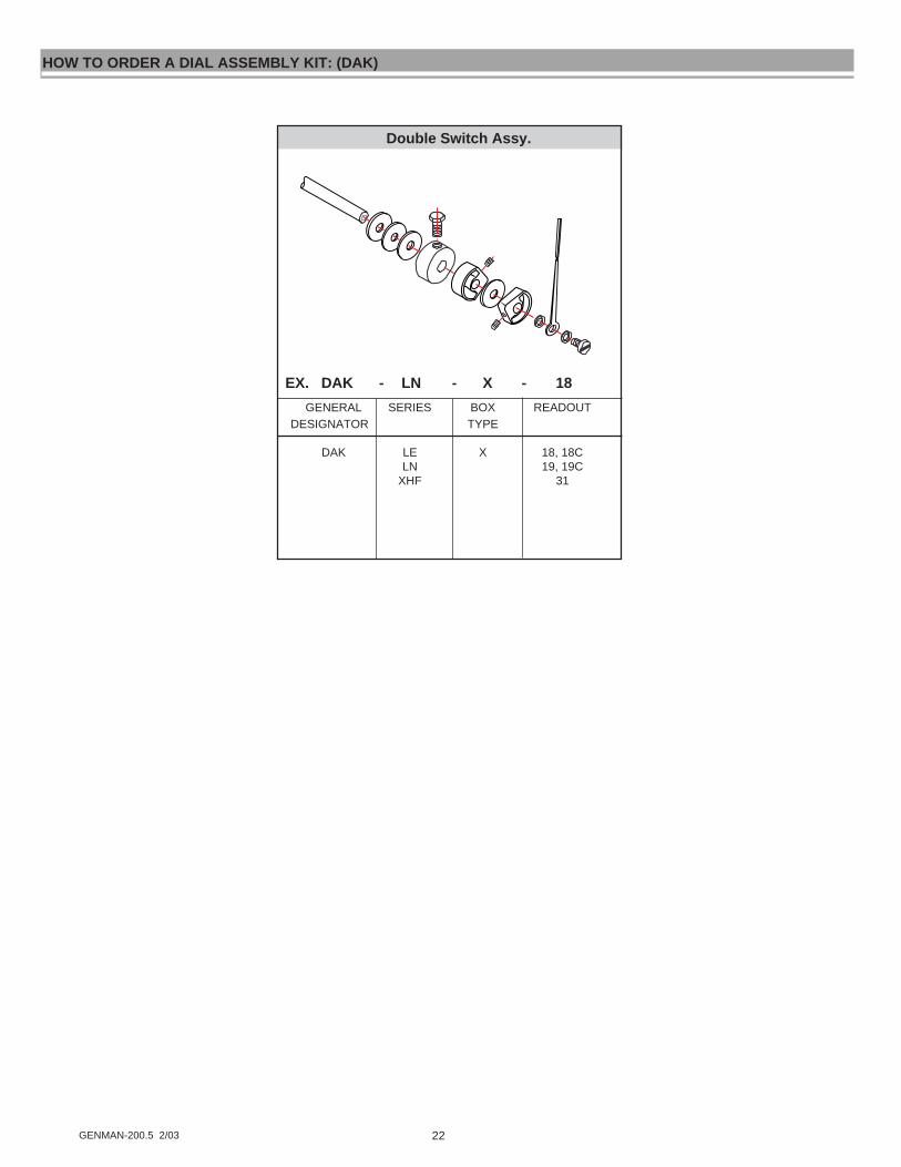
22GENMAN-200.5 2/03
GENERAL SERIES BOX READOUTDESIGNATOR TYPE
DAK LE X 18, 18CLN 19, 19C
XHF 31
EX. DAK - LN - X - 18
HOW TO ORDER A DIAL ASSEMBLY KIT: (DAK)
Double Switch Assy.

23 GENMAN-200.5 2/03
GENERAL SERIES BOX READOUT OPTIONSDESIGNATOR TYPE
ROK LL A 0LP M 1, 1BLH R 2, 2BSN T 3 CESM X 4SH 61 HTMN 62MM 53MH 54LN 71LE 72
XHF 7, 7CSX 18, 18CMX 17, 17CML 19, 19C
303111
EX. ROK - MN - A - 1 - HT
The meters in this manual are all mechanical in nature. The flow elements are connected to the control boxes via a shaftthat rotates with changing flow rates. The parts that are actuated by this mechanical action that reside inside of the controlbox are called the “Readout”. If any of these parts are damaged, the replacement parts are sold as a kit. All “ReadoutAssembly” kit part numbers begin with “ROK”. The remainder of the part number is derived from the model code of themeter. The part numbers correlate to the model codes as follows:
MN-BSB30GM-8-32V1.0 -A1NR
ROK-MN-A-1
The following kit diagrams are subsets of the main parts assembly. The accompanying diagrams will clarify which parts areincluded for each flow meter series.
HOW TO ORDER A READOUT KIT: (ROK)
Double Switch Assy.
Insulator usedwith R box.
GENERAL SERIES BOX READOUT OPTIONSDESIGNATOR TYPE
ROK ALL A 1, 1B CER 3 HTT 61M 53
71
EX. ROK - LL - A - 1B - CE
Single Switch Assy.
Insulator usedwith R box &T Box.
GENERAL SERIES BOX READOUT OPTIONSDESIGNATOR TYPE
ROK ALL A 2, 2B CER 4 HT
546272
EX. ROK - LL - A - 2B - CE
24GENMAN-200.5 2/03
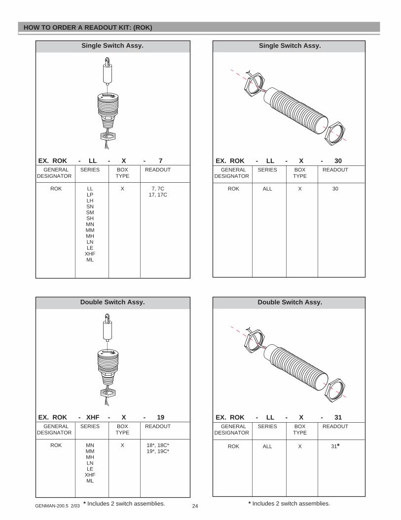
GENERAL SERIES BOX READOUTDESIGNATOR TYPE
ROK LL X 7, 7CLP 17, 17CLHSNSMSHMNMMMHLNLE
XHFML
HOW TO ORDER A READOUT KIT: (ROK)
EX. ROK - LL - X - 7
Single Switch Assy.
GENERAL SERIES BOX READOUTDESIGNATOR TYPE
ROK ALL X 30
EX. ROK - LL - X - 30
Single Switch Assy.
GENERAL SERIES BOX READOUTDESIGNATOR TYPE
ROK MN X 18*, 18C*MM 19*, 19C*MHLNLE
XHFML
EX. ROK - XHF - X - 19
Double Switch Assy.
GENERAL SERIES BOX READOUTDESIGNATOR TYPE
ROK ALL X 31*
EX. ROK - LL - X - 31
Double Switch Assy.
* Includes 2 switch assemblies.* Includes 2 switch assemblies.
25 GENMAN-200.5 2/03
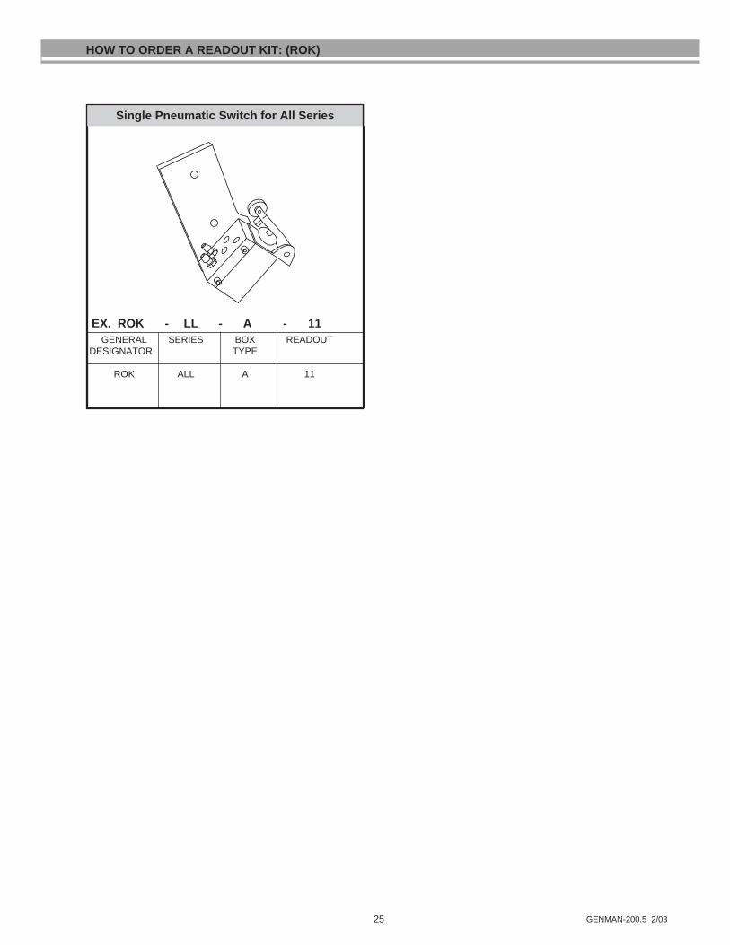
GENERAL SERIES BOX READOUTDESIGNATOR TYPE
ROK ALL A 11
EX. ROK - LL - A - 11
Single switch assy.
HOW TO ORDER A READOUT KIT: (ROK)
Single Pneumatic Switch for All Series

26GENMAN-200.5 2/03
HOW TO ORDER A COVER ASSEMBLY KIT: (CAK)
MN-BSB30GM-8-32V1.0-A1WR-HT
How to order a Cover Assembly Kit:
EX. CAK - LL - A - W - HT
GENERAL SERIES BOX ENCLOSURE OPTIONSDESIGNATOR TYPE TYPE
CAK LL LN A N,W,X HTLP LE M W or X CLH XHF R W or X TGSN SX T W or X CESM MX X W or XSH ML RTZ W or XMN TTZ W or XMM
*CAK-MN-A-H
GENERAL SERIES BOX ENCLOSURE OPTIONSDESIGNATOR TYPE TYPE
CAK SN A N CSM W HTSH X TGMN CEMMMHSXMXML
EX. CAK - SN - A - W - HT
A Box (Vane Style) A Box (Piston Style)
EX. CAK - LL - A - N - HT
GENERAL SERIES BOX ENCLOSURE OPTIONSDESIGNATOR TYPE TYPE
CAK LL A N CLP W HTLH X TG
CE
®UNIVERSAL FLOW M
ONITORS, INC.
1755 E. Nine M
ile Road, Hazel P
ark, MI 4
8030
313-524-9635
MODEL NUMBER
UNIVERSAL NO.
ITEM NO.
TYPE
UNIVERSAL FLOW RATE IN
DICATOR
®
43
21
0
13
5
®UNIVERSAL FLOW M
ONITORS, INC.
1755 E. Nine M
ile Road, Hazel P
ark, MI 4
8030
313-524-9635
MODEL NUMBER
UNIVERSAL NO.
ITEM NO.
TYPE
UNIVERSAL FLOW RATE IN
DICATOR
®4
32
10
13
5
*“ ” HT Option at the end of the model code requires an “HT” designator in the kit part number for high temperatureapplications (not available with “N” type control boxes, SX, MX, or ML meters).NOTE: Model number and UFM # must be supplied with order to stamp new name plate.The following kit diagrams are subsets of the main assembly. The accompanying diagrams will clarify which parts are included.
The meters in this manual are all mechanical in nature. The flow elements are connected to the control boxes via a shaftthat changes angle with changing flow rates. If any of these parts are damaged, the replacement parts are sold as a kit.All “Cover Assembly Kits” part numbers begin with “CAK”. The remainder of the part number is derived from the modelcode of the meter. The part numbers correlate to the model codes as follows:
Flow Any Direction Flow Any Direction
27 GENMAN-200.5 2/03
HOW TO ORDER A COVER ASSEMBLY KIT: (CAK)
®
UNIVERSAL FLOW MONITORS, IN
C.
1755 E. Nine M
ile Road, Hazel P
ark, MI 4
8030
313-524-9635
43
21
0
13
5
MODEL NUMBER
UNIVERSAL NO.
ITEM NO.
TYPE
UNIV
ERSAL
FLOWRATE INDICATOR
R Box (Flow to Left)
®
UNIVERSAL FLOW MONITORS, IN
C.
1755 E. Nine M
ile Road, Haze
l Park,
MI 4
8030
313-524-9635
43
21
0
13
5
MODEL NUMBER
UNIVERSAL NO.
ITEM NO.
TYPE
UNIVERSAL FLOWRATE
INDIC
ATOR
®
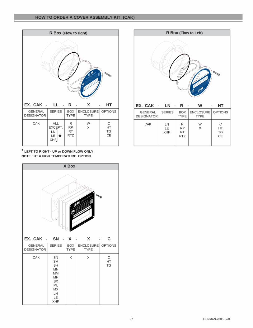
R Box (Flow to right)
X Box
EX. CAK - LL - R - X - HT
GENERAL SERIES BOX ENCLOSURE OPTIONSDESIGNATOR TYPE TYPE
CAK ALL R W CEXCEPT: RP X HT
RT TGRTZ CE
LNLE
XHF *
* LEFT TO RIGHT - UP or DOWN FLOW ONLYNOTE : HT = HIGH TEMPERATURE OPTION.
EX. CAK - LN - R - W - HT
GENERAL SERIES BOX ENCLOSURE OPTIONSDESIGNATOR TYPE TYPE
CAK R W CRP X HTRT TG
RTZ CE
EX. CAK - SN - X - X - C
GENERAL SERIES BOX ENCLOSURE OPTIONSDESIGNATOR TYPE TYPE
CAK SN X X CSM HTSH TGMNMMMHSXMLMXLNLE
XHF
LNLE
XHF
® UNIVERSAL FLOW MONITORS, INC.
1755 E. Nine Mile Road, H
azel Park, M
I 48030
313-524-9635
MODEL NUMBER
UNIVERSAL NO.
ITEM NO.
UNIVERSAL FLOW RATE IN
DICATOR
®
43
21
0
13
5

28GENMAN-200.5 2/03
HOW TO ORDER A COVER ASSEMBLY KIT: (CAK)
T Box (Flow to right)
EX. CAK - LL - T - X - HT
GENERAL SERIES BOX ENCLOSURE OPTIONSDESIGNATOR TYPE TYPE
CAK ALL T X CEXCEPT: HT
TG
LNLE
XHF*
* LEFT TO RIGHT, UP OR DOWN FLOW ONLY
®
UNIVERSAL FLOW MONITORS, INC.
1755 E. Nine Mile Road, H
azel Park, M
I 48030
313-524-9635
MODEL NUMBER
UNIVERSAL NO.
ITEM NO.
TYPE
UNIVERSAL FLOW RATE IN
DICATOR
®
43
21
0
13
5
M Box
EX. CAK - LL - M - W - C
GENERAL SERIES BOX ENCLOSURE OPTIONSDESIGNATOR TYPE TYPE
CAK LL M W CLP HTLHSNSMSHSXMXMNMHMM
Any Direction
T Box (Flow to left)
EX. CAK - LN - T - X - HT
GENERAL SERIES BOX ENCLOSURE OPTIONSDESIGNATOR TYPE TYPE
CAK LN T X CLE HT
XHF TG
FLOW RIGHT TO LEFT ONLY
®
UNIVERSAL FLOW MONITORS, INC.
1755 E. Nine Mile Road, H
azel Park, M
I 48030
313-524-9635
MODEL NUMBER
UNIVERSAL NO.
ITEM NO.
TYPE
UNIVERSAL FLOW RATE IN
DICATOR
®
43
21
0
13
5
®
MODEL NUMBER
UNIVERSAL NO. ITEM NO.
TYPE
UNIVERSAL FLOW RATE INDICATOR
PATENT PENDING
UNIVERSAL
FLOW MONITORS, INC.
1755 E. Nine Mile Road
Hazel Park, MI 48030
313-524-9635
WARNING: ELECTRICAL HAZARD
DISCONNECT POWER BEFORE SERVICING

29 GENMAN-200.5 2/03
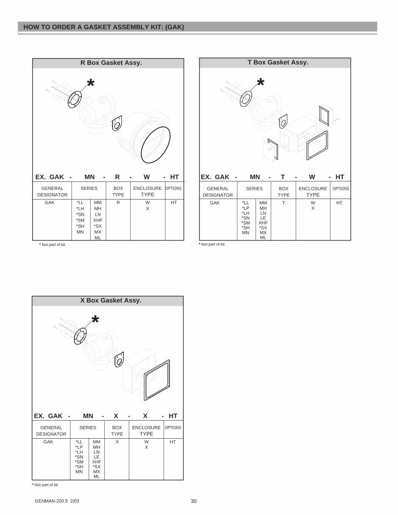
The meters in this manual are all mechanical in nature. The flow elements are connected to the control boxes via a shaftthat changes angle with changing flow rates. The various parts of the meters are sealed from the atmosphere by gaskets.If any of these gaskets are damaged, the replacement parts are sold as a kit. All “Gasket Assembly” kit part numbersbegin with “GAK”. The remainder of the part number is derived from the model code of the meter. The part numberscorrelate to the model codes as follows:
MN-BSB30GM-8-32V1.0-A1WR-HT
GAK-MN-A-W-H
How to order a Gasket Kit:
EX. GAK - LL - T - W - HT
GENERAL SERIES BOX ENCLOSURE OPTIONSDESIGNATOR PRESSURE TYPE TYPE
GAK LL A N HTLP M WLH R XSN TSMSHMNMMMHLNLE
XHFSXMXML
HOW TO ORDER A GASKET ASSEMBLY KIT: (GAK)
*
*“ ”HT option at the end of the model code requires an “HT” designator in the kit part number for high temperature applica-tions (not available with “N” type control boxes, SX, MX, or ML meters).The following kit diagrams are subsets of the main assembly.The accompanying diagrams will clarify which parts are included.
EX. GAK - MN - A - W - HT
A Box Gasket Assy.
GENERAL SERIES BOX ENCLOSURE OPTIONSDESIGNATOR TYPE TYPE
GAK *LL MN A N HT*LP MM W*LH MH X*SN *SX*SM MX*SH ML
*
* Not part of kit
EX. GAK - MN - M - W - HT
M Box Gasket Assy.
GENERAL SERIES BOX ENCLOSURE OPTIONSDESIGNATOR TYPE TYPE
GAK *LL MN M N HT*LP MM W*LH MH*SN *SX*SM MX*SH ML
*
30GENMAN-200.5 2/03
HOW TO ORDER A GASKET ASSEMBLY KIT: (GAK)
X Box Gasket Assy.
EX. GAK - MN - X - X - HT
GENERAL SERIES BOX ENCLOSURE OPTIONSDESIGNATOR TYPE TYPE
GAK *LL MM X W HT*LP MH X*LH LN*SN LE*SM XHF*SH *SXMN MX
ML
*
* Not part of kit
T Box Gasket Assy.
EX. GAK - MN - T - W - HT
GENERAL SERIES BOX ENCLOSURE OPTIONSDESIGNATOR TYPE TYPE
GAK *LL MM T W HT*LP MH X*LH LN*SN LE*SM XHF*SH *SXMN MX
ML
*
* Not part of kit
R Box Gasket Assy.
EX. GAK - MN - R - W - HT
GENERAL SERIES BOX ENCLOSURE OPTIONSDESIGNATOR TYPE TYPE
GAK *LL MM R W HT*LH MH X*SN LN*SM XHF*SH *SXMN MX
ML
*
* Not part of kit

31 GENMAN-200.5 2/03
The meters in this manual are all mechanical in nature. The flow elements are connected to the control boxes via a shaft thatrotates with changing flow rates. The fluid is prevented from leaking out of the flow meter body by O-rings acting as “seals”. Ifany of these seals are damaged, the replacement parts are sold as a kit. All “Seal Assembly” kits part numbers begin with“SAK”. The remainder of the part number is derived from the model code of the meter. The part numbers correlate to themodel codes as follows:
MN-BSB30GM-8-32V1.0-A1NR
SAK-MN-B-A
GENERAL SERIES SEAL BOX AIR ORDESIGNATOR MATERIAL TYPE GAS UNIT
SAK LL B A GLP E M (NoLH F R SymbolSN J T forSM T X Liquids)SH KMN HMM AMHLNLE
XHFSXMXML
EX. SAK - MN - B - A - G
The following kit diagrams are subsets of the main parts assembly kit. The accompanying diagrams will clarify which parts areincluded for each flow meter series.
HOW TO ORDER A SEAL ASSEMBLY KIT: (SAK)
EX. SAK - SN - B - S - R - GGENERAL SERIES SEAL INTERNALS BOX AIR OR
DESIGNATOR MATERIAL TYPE GAS UNIT
SAK SN B S A GSM E I M (NoSH F T R Symbol*SX J H RT for
T L RP Liquids)K C TH R XA P
NOTE: SHAFT IS INCLUDED IN SMALL SERIES (SN,SM,SH,SX) ONLY.* SX Series requires additional static seals for port adaptors.
Small Vane Style
yyy
yyyy
yyyy
yyyy
yyyy
yyyy
This seal included in SAK with SHhousings only.Thrust Bearing for SH housing
only.
*
*
The glydring isadded to this partslist for transmittingand air or gas units.It is standard on SM& SH Seriesmonitors

32GENMAN-200.5 2/03
yy
yyyy
yyyyy
yyy
yy
yyyy
yyyy
yyy
HOW TO ORDER A SEAL ASSEMBLY KIT: (SAK)
GENERAL SERIES SEAL BOX AIR ORDESIGNATOR MATERIAL TYPE GAS CAL.
SAK LL B A GLP E M (NoLH F R Symbol
J RT forT RP Liquids)K TH X
EX. SAK - LL - F - T - G
GENERAL SERIES SEAL BOX AIR ORDESIGNATOR MATERIAL TYPE GAS CAL.
SAK MN B A GMM E M (NoMH F R SymbolML J RP forMX T RT Liquids)
K TH XA
EX. SAK - MN - B - R - G
yyy
yyyy
yyyy
yy
yyyy
yyyyy
yyyy
yy
*
*EPR O-Rings swell when in contact with oil, grease or petroleumbased fluids. The shaft seals will have one Buna-N sealsubstituted for the EP o-ring for use in the "spring pocket".** MX Series with port adaptors require static seals.(See drawing to right)
Medium Vane Style
Piston Style
**
**The glydring isadded to this partslist for transmittingand air or gas units.It is standard onMM ,MH, & MLSeries monitors
The glydring isstandard on all pistonstyle monitors.

33 GENMAN-200.5 2/03
HOW TO ORDER A SEAL ASSEMBLY KIT: (SAK)
GENERAL SERIES SEAL BOX AIR ORDESIGNATOR MATERIAL TYPE GAS CAL.
SAK XHF B M GE R (NoF RT SymbolJ RP forT T Liquids)K XHA
EX. SAK - XHF - B - R - G
yyyyy
yyyy
yy
yy
yyyy
yyyy
yy
The glydrings are astandard part, andis used for bothliquids and gases.
GENERAL SERIES SEAL BOX AIR ORDESIGNATOR MATERIAL TYPE GAS CAL.
SAK LN B M GLE E R (No
F RP SymbolJ RT forT T Liquids)K XHA
EX. SAK - LN - B - R - G
yyyy
yyyy
yyyy
yy
yyyy
yyyy
yyy
The glydrings are astandard part, andis used for bothliquids and gases.
Large Vane Style
XHF Vane Style

34GENMAN-200.5 2/03
NOTICERETURN MATERIAL AUTHORIZATION
Please read the following UFM policy information carefully. By following the guidelines outlinedbelow you will assist in providing a timely evaluation and response regarding the status of your flowmeter. UFM evaluates all AUTHORIZED RETURNED MATERIALS in a timely manner and will promptlyprovide notification regarding the status of the related materials and/or a written quotation indicatingthe total charges and description of the necessary repairs.
1. All returns must have a RMA form completed by the customer.2. Any meter returned that was previously in service must have the OSHA requirements completed and
a MSDS included where applicable.3. An RMA number will only be issued when UFM has received a copy of the completed RMA form and
any applicable MSDS.4. A "Return Goods" shipping label (located in the back of the Instruction Manual) must be used for
returning materials to UFM.5. A purchase order must accompany all returns to cover the cost of the repair evaluations.6. Returned goods must be shipped prepaid or they will be rejected.
REPAIRABLE MA TERIALWritten authorization to proceed with the repair under the assigned Purchase Order, must be received within30 days of repair quotation. If the unit(s) are repaired, the $90.00 evaluation charge will be applied to thequoted repair costs. If no repairs are authorized within this 30 day period, the customer will be billed $90.00plus shipping charges and the materials will be returned to the customer.
NON-REPAIRABLE MA TERIALA written notice that the material is not repairable will be provided to the customer by UFM. If no dispositionto scrap or return the material is received from the customer within 30 days, unrepairable material will bescrapped and the customer will be billed the $90.00 evaluation charge. If a UFM replacement unit is pur-chased within 30 days of non-repairable condition notice, the $90.00 evaluation fee will be waived. The returnof non-repairable materials may be ordered by customer Purchase Order providing for shipping and handlingcharges.
RETURN FOR RESTOCKAll goods returned for restock adjustment must be:A. New and unused.B. Returned to the factory within ONE YEAR of date of original shipment.C. Returned through the distributor where the goods were originally purchased.This material will also be subject to an evaluation charge of $90.00 and must be accompanied by a PurchaseOrder.
The customer will be advised of the restocking adjustment for all restockable goods. Upon acceptance of therestocking adjustment, by the customer, the $90.00 evaluation fee will be waived and a credit issued by UFMagainst the assigned Purchase Order. The customer will be advised of any non-restockable goods and willbe charged the $90.00 evaluation fee plus any shipping charges if returned to the customer.
If no disposition is received by UFM within 30 days, the goods will be scrapped and the $90.00 evaluation feewill be billed.
WARRANTY RETURNSWarranty returns must be accompanied by a Purchase Order and must be shipped prepaid to UFM. UFM willreview the goods and advise the customer of the evaluation and validity of the warranty claim. Valid warrantyclaims will be repaired or replaced at no charge. No evaluation fee will be charged to repairs made undervalid warranty. Return shipping costs will be prepaid by UFM. Should UFM determine the returned materialis not defective under the provisions of UFM's standard warranty, the customer will be advised of neededrepairs and associated costs. All materials returned without a valid warranty will be subject to the "Repair-able Material " policy outlined above.
Form RMAP-100

35 GENMAN-200.5 2/03
Customer:Ship To:
Contact Name:Return P.O.#Phone#FAX#
Product Information Qty:Model Code:Universal #:Operating Temp: Max Temp:Operating Pressure: Max Pressure:Viscosity Specific GravityDate Purchased: Date Installed:
IMPORTANT: This form must be filled out completely and faxed to UFM Repair Department prior to UFM issuing a RMA #
U N I V E R S A L
FLOW MONITORSFLOW MONITORS
RETURN MATERIAL AUTHORIZATION(RMA) REQUEST FORM
FAX TO: UFM Repair Department (810) 398-4274
ElectronicsNo signalInaccurate signalRemote Readout(MENSAH ) Digital DisplaySignal at no flowOther (describe below)
Reason for return: (Please be detailed as possible. Lack of Information may increase labor charges. )MechanicalMeter leaksPointer sticksPointer is not accurate (calibration off)Alarm switch does not workOther (describe below)
Details:
Note: There will be a minimum evaluation charge of $90.00 for all units returned (excluding units covered under warranty).Units WILL NOT be accepted without a valid UFM Return Material Authorization Number (RMA#). A Material Safety DataSheet on the process fluid must be received by UFM when applicable, prior to the RMA# being issued.
* OSHA Requirements: (to be filled out by customer) NO EXCEPTIONS!!
Process Fluid:Meter must be flushed to remove all process fluids.
I hereby certify that the material being returned has been properly flushed and cleaned of all hazardousmaterials and does not require any special handling.
Print or Type Name Signature:
Title Date:
Distributor Information INTERNAL USE ONLYCompany NameContact NameP.O. #Phone# FAX#
RMA#Authorized byDate
Document #: 1400.8 Revision #: 2 Revision Date: 1/18/95 Approved By: Approval Date:Distribution: GENMAN, VORTEX, INSITE, OCTOPUS, MENSAH 140, MENSAH 145, TRANSMITTER, GDN, GDNL

36GENMAN-200.5 2/03
DO NOT REMOVE THIS PAGE.
PLEASE COPY RMA FORM.

37 GENMAN-200.5M 3/97
FROM:
REMINDER: PLEASE INCLUDE MSDS INFORMATION
TO:
UNIVERSAL FLOW MONITORS, INC.ATTN: RETURNS/REPAIRS DEPT.1755 EAST NINE MILE ROADHAZEL PARK, MI 48030-0249U.S.A.
CUSTOMER:RMA#:RUSH DELIVERY REQUIRED: (CIRCLE ONE) YES NO
FROM:
REMINDER: PLEASE INCLUDE MSDS INFORMATION
TO:
UNIVERSAL FLOW MONITORS, INC.ATTN: RETURNS/REPAIRS DEPT.1755 EAST NINE MILE ROADHAZEL PARK, MI 48030-0249U.S.A.
CUSTOMER:RMA#:RUSH DELIVERY REQUIRED: (CIRCLE ONE) YES NO
FROM:
REMINDER: PLEASE INCLUDE MSDS INFORMATION
TO:
UNIVERSAL FLOW MONITORS, INC.ATTN: RETURNS/REPAIRS DEPT.1755 EAST NINE MILE ROADHAZEL PARK, MI 48030-0249U.S.A.
CUSTOMER:RMA#:RUSH DELIVERY REQUIRED: (CIRCLE ONE) YES NO

38GENMAN-200.5 2/03

39 GENMAN-200.5 2/03
U N I V E R S A L
FLOW MONITORSFLOW MONITORS
UNIVERSAL FLOW MONITORS, INC.1755 East Nine Mile RoadP.O. Box 249, Hazel Park, MI 48030-0249(248)542-9635 / FAX (248) 398-4274
Notes

40GENMAN-200.5 2/03Litho in USA
U N I V E R S A L
FLOW MONITORSFLOW MONITORS
R
UNIVERSAL FLOW MONITORS INC.1755 E. Nine Mile Road
Hazel Park, MI 48030-0249Ph. 248-542-9635 / Fax 248-398-4274
www.universalflow.com