univac minuteman weapon system computer plated wire
TRANSCRIPT

A Legacy Project Paper
©2010, VIP Club Page 1 of 5
UNIVAC Minuteman Weapon System Computer Plated Wire Memory Usage
Addendum By Larry D. Bolton and Clinton D. Crosby
Since the original Minuteman Plated Wire article was written in 2008, the VIP Club Legacy Committee has been in the process of reviewing several thousand archived photos and negatives. During that review, we have uncovered additional photos of the plated wire process that may be of interest in continuing the documentation of this technology. This addendum adds this information. The original paper can be found at http://vipclubmn.org/Documents/PlatedWire.pdf Figure A1 shows the machine used to draw down the beryllium copper substrate from the purchased 20 mil diameter wire to the desired 5 mil diameter wire. The photo shows four cones with a die retaining box between each of two cone pairs. Each die retaining box contains a series of successively smaller dies (10 dies in each box) through which the wire is fed. Twenty dies (total) are used to draw the wire down to the finished 5 mil diameter wire. Above each cone is a copper tube with holes which supplies a constant stream of lubricating oil to the wire. As the size of the wire becomes smaller, its length increases proportionally. The wire is fed at the rear, thru the first die, around the small end of the cone, back thru the next smaller die, around the next larger step in the cone, and so forth to the last front step where it is wound on another reel or spool. Motors in the rear of the machine rotate the cones and take-up reels to pull the wire through. This machine completes the reduction from a 20 mil to the 5 mil diameter in one pass.
Figure A1: Beryllium Copper Wire Drawing Machine (photo 5646-4)

A Legacy Project Paper
©2010, VIP Club Page 2 of 5
Figures A2 and A3 show the actual wire plating machine. The larger spoke wheel on the left is the supply reel for the 5 mil bare beryllium copper wire. The beryllium copper wire passes through a series of plastic cells containing various solutions to clean, copper plate, nickel iron plate, and rinse the wire in a continuous plating process. Magnetizing coils (yellow coils) align the magnetic material during the plating process. An annealing oven is located just prior to the wire being coated with a corrosion inhibitor. The magnetic material is tested. Wire passing several on-line tests is cut into 18 inch lengths.
Figure A2: Wire Plating Machine (photo 5646-1)

A Legacy Project Paper
©2010, VIP Club Page 3 of 5
Figure A3: Wire Plating Machine (alternate view, photo 5646-3)
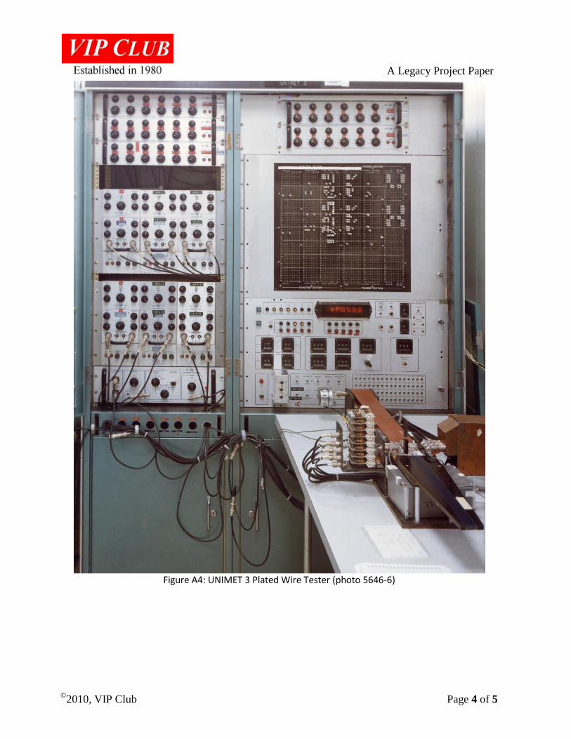
Figure A4 shows the automated Universal Magnetic Element Tester (UNIMET) serial number 3 Plated Wire Tester. Individual tests are programmed via the front panel plugboard. This tester tests the electromagnetic properties of single plated wires for the entire length of the wire. The holder is on the lower right of the picture. A support tray is at the front and a moving conveyor belt is at the rear. The test head is between them.
A Legacy Project Paper
©2010, VIP Club Page 4 of 5
Figure A4: UNIMET 3 Plated Wire Tester (photo 5646-6)
A Legacy Project Paper
©2010, VIP Club Page 5 of 5
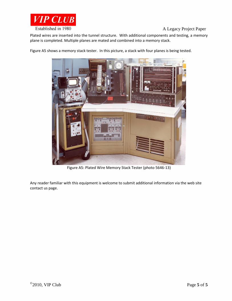
Plated wires are inserted into the tunnel structure. With additional components and testing, a memory plane is completed. Multiple planes are mated and combined into a memory stack. Figure A5 shows a memory stack tester. In this picture, a stack with four planes is being tested.
Figure A5: Plated Wire Memory Stack Tester (photo 5646-13)
Any reader familiar with this equipment is welcome to submit additional information via the web site contact us page.