univ. of tehrancomputer network1 special topics on wireless ad-hoc networks university of tehran...
TRANSCRIPT

Univ. of Tehran Computer Network 1
Special TopicsSpecial Topics on on
Wireless Ad-hoc Wireless Ad-hoc NetworksNetworks
University of TehranDept. of EE and Computer Engineering
By:Dr. Nasser Yazdani
Lecture 12: TCP on Wireless TCP on Wireless NetworkNetwork

Univ. of Tehran Computer Network 2
Covered topicsCovered topics How to run applications on wireless
network? Transport layer
References Chapter 5 of the book Hari Balakrishnan, Venkata N. Padmanabhan,
Srinivasan Seshan and Randy H. Katz, “A Comparison of Mechanisms for Improving TCP Performance over Wireless Links”
Univ. of Tehran Computer Network 3
OutlineOutline TCP basics Layer 4 consideration:
Impact of transmission errors on TCP performance
Timeout Approaches to improve TCP
performance Approaches to improve application
performance

Univ. of Tehran Computer Network 4
TCP BasicsTCP Basics Reliable ordered delivery
End-to-end semantics Acknowledgements sent to TCP sender confirm
delivery of data received by TCP receiver Ack for data sent only after data has reached receiver
TCP window flow control is “self-clocking” New data sent when old data is ack’d Helps maintain “equilibrium”
Implements congestion avoidance and control
Univ. of Tehran Computer Network 5
Window Based Flow Control
TCP sender sets retransmission timer for only one packet. If ack for the timed packet is not received the packet is assumed to be lost
RTO dynamically calculated Congestion window size bounds the
amount of data that can be sent per round-trip time
Throughput <= W / RTT

Univ. of Tehran Computer Network 6
Retransmission Timeout (RTO)
RTO = mean + 4 mean deviation Standard deviation average of
(sample – mean) Mean deviation average of |sample – mean| Mean deviation easier to calculate than standard
deviation Mean deviation is more conservative
Large variations in the RTT increase the deviation, leading to larger RTO
2
2

Univ. of Tehran Computer Network 7
Timeout Granularity RTT is measured as a discrete variable,
in multiples of a “tick” 1 tick = 500 ms in many
implementations smaller tick sizes in more recent
implementations (e.g., Solaris) RTO is at least 2 clock ticks Double RTO on each timeout
(Exponential backoff)

Univ. of Tehran Computer Network 8
Congestion Collapse and Efficiency
knee – point after which throughput increases slowly delay increases quickly
cliff – point after which throughput decreases
quickly to zero (congestion collapse)
delay goes to infinity Congestion avoidance
stay at knee Congestion control
stay left of (but usually close to) cliff
Note (in an M/M/1 queue) delay = 1/(1 – utilization)
Load
Load
Th
rou
ghp
ut
De
lay
knee cliff
over utilization
under utilization
saturation
congestion collapse

Univ. of Tehran Computer Network 9
Goals Operate near the knee point Remain in equilibrium How to maintain equilibrium?
Don’t put a packet into network until another packet leaves. How do you do it?
Use ACK: send a new packet only after you receive and ACK. Why?
Maintain number of packets in network “constant”
Univ. of Tehran Computer Network 10
Congestion Control TCP assume packet loss is due to
congestion On packet loss, reduces the
congestion window and consequently amount of data sent per RTT throughput may decrease

Univ. of Tehran Computer Network 11
Congestion Avoidance and Control
Slow Start initially, congestion window size cwnd = 1
MSS (maximum segment size) increment window size by 1 MSS on each
new ack slow start phase ends when window size
reaches the slow-start threshold cwnd grows exponentially with time during
slow start
Univ. of Tehran Computer Network 12
Fast Retransmit Mechanism
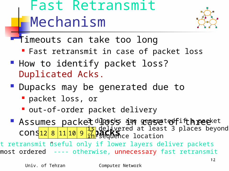
Timeouts can take too long Fast retransmit in case of packet loss
How to identify packet loss? Duplicated Acks. Dupacks may be generated due to
packet loss, or out-of-order packet delivery
Assumes packet loss in case of three consecutive dupacks
12 8 791011
3 dupacks are generated if a packetis delivered at least 3 places beyond itsin-sequence location
Fast retransmit useful only if lower layers deliver packets“almost ordered” ---- otherwise, unnecessary fast retransmit

Univ. of Tehran Computer Network 13
Congestion Avoidance On each new
ack, increase cwnd by 1/cwnd packets
cwnd increases linearly with time during congestion avoidance
0
2
4
6
8
10
12
14
0 1 2 3 4 5 6 7 8
Time (round trips)
Con
gest
ion
Win
dow
size
(s
egm
ents
)Slow start
Congestionavoidance
Slow start threshold
Example assumes that acks are not delayed

Univ. of Tehran Computer Network 14
Congestion Control -- Timeout
On a timeout, the congestion window is reduced to the initial value of 1 MSS
The slow start threshold is set to half the window size before packet loss more precisely,
ssthresh = maximum of min(cwnd,receiver’s advertised window)/2 and 2 MSS
Slow start is initiated

Univ. of Tehran Computer Network 15
0
5
10
15
20
25
Time (round trips)
Con
gest
ion
win
dow
(se
gmen
ts)
ssthresh = 8 ssthresh = 10
cwnd = 20
After timeout
Univ. of Tehran Computer Network 16
Fast recovery Fast retransmit occurs when multiple (>= 3)
dupacks come back Fast recovery follows fast retransmit Different from timeout : slow start follows
timeout timeout occurs when no more packets are getting
across fast retransmit occurs when a packet is lost, but
latter packets get through ack clock is still there when fast retransmit occurs no need to slow start
Univ. of Tehran Computer Network 17
Fast Recovery ssthresh = min(cwnd, receiver’s advertised
window)/2 (at least 2 MSS) retransmit the missing segment (fast
retransmit) cwnd = ssthresh + number of dupacks when a new ack comes: cwnd = ssthreh
enter congestion avoidance
Congestion window cut into half
Univ. of Tehran Computer Network 18
0
2
4
6
8
10
Time (round trips)
Win
dow
size
(seg
men
ts)
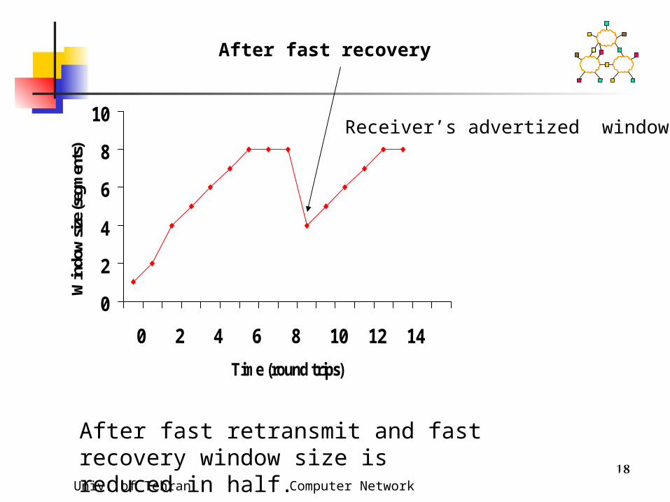
After fast retransmit and fast recovery window size isreduced in half.
Receiver’s advertized window
After fast recovery

Univ. of Tehran Computer Network 19
Outline
TCP basics Impact of transmission errors on TCP
performance Approaches to improve TCP
performance Classification Discussion of selected approaches

Univ. of Tehran Computer Network 20
Random Errors If number of errors is small, they may be
corrected by an error correcting code Excessive bit errors result in a packet being
discarded, and Dup Acks. Dups Acks cause Fast retransmit which
results in retransmission of lost packet reduction in congestion window
Reducing congestion window in response to errors is unnecessary and reduces the throughput
Univ. of Tehran Computer Network 21
Congestion Response to Errors
On a CDMA channel, errors occur due to interference from other user, and noise Interference due to other users is an indication of
congestion. If such interference causes transmission errors, it is appropriate to reduce congestion window
If noise causes errors, it is not appropriate to reduce window
When a channel is in a bad state for a long duration, it might be better to let TCP backoff, so that it does not unnecessarily attempt retransmissions while the channel remains in the bad state.

Univ. of Tehran Computer Network 22
Burst Errors May Cause Timeouts
If a wireless link remains unavailable for extended duration, a window worth of data may be lost Timeout might occur
Timeout results in slow start and reduces congestion window to 1 MSS, which reduces throughput
Unfortunately, TCP cannot distinguish between packet losses due to congestion and transmission errors

Univ. of Tehran Computer Network 23
Improving TCPHow to improve performance? Hide error losses from the sender TCP
Not reduce congestion window Let sender determine cause of packet loss
if it is due to errors, it will not reduce congestion window.
where modifications are needed? At the sender node At the receiver node At intermediate node(s) Combinations of the above
Univ. of Tehran Computer Network 24
Ideal Behavior Ideal TCP behavior: TCP sender should retransmit
a packet lost due to transmission errors, without taking any congestion control actions Ideal TCP typically not realizable
Ideal network behavior: Transmission errors should be hidden from the sender -- the errors should be recovered transparently and efficiently
Proposed schemes attempt to approximate one of the above two ideals
Univ. of Tehran Computer Network 25
Various Schemes Link level mechanisms Split connection approach TCP-Aware link layer TCP-Unaware approximation of TCP-
aware link layer Explicit notification
Receiver-based discrimination Sender-based discrimination

Univ. of Tehran Computer Network 26
Link Layer MechanismsLink Layer Mechanisms Forward Error Correction (FEC)
FEC incurs overhead even when errors do not occur
Adaptive FEC schemes can reduce the overhead by choosing appropriate FEC dynamically
Link level retransmission in case of error in the link layer.
FEC to correct a small number of errors link level retransmission when FEC
capability is exceeded

Univ. of Tehran Computer Network 27
Link Level Retransmissions
wireless
physical
link
network
transport
application
physical
link
network
transport
application
physical
link
network
transport
application
rxmt
TCP connection
Link layer state

Univ. of Tehran Computer Network 28
Link Level RetransmissionsIssues
How many times to retransmit at the link level before giving up? Finite bound -- semi-reliable link layer No bound -- reliable link layer
What triggers link level retransmissions? Link layer timeout mechanism Link level acks (negative acks, dupacks, …) Other mechanisms (e.g., Snoop, as discussed
later) How much time is required for a link layer
retransmission? Small fraction of end-to-end TCP RTT Large fraction/multiple of end-to-end TCP RTT
Univ. of Tehran Computer Network 29
Link Level RetransmissionsIssues
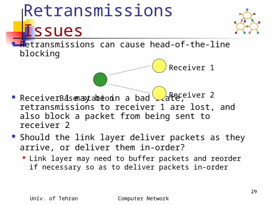
Retransmissions can cause head-of-the-line blocking
Receiver 1 may be in a bad state, retransmissions to receiver 1 are lost, and also block a packet from being sent to receiver 2
Should the link layer deliver packets as they arrive, or deliver them in-order? Link layer may need to buffer packets and reorder if
necessary so as to deliver packets in-order
Base station
Receiver 1
Receiver 2

Univ. of Tehran Computer Network 30
Link Level Retransmissions
The sender’s Retransmission Timeout (RTO) is a function of measured RTT (round-trip times) Link level retransmits increase RTT, therefore,
RTO If errors not frequent, RTO will not account for
RTT variations due to link level retransmissions When errors occur, the sender may timeout &
retransmit before link level retransmission is successful
Sender and link layer both retransmit Duplicate retransmissions (interference) waste
wireless bandwidth Timeouts also result in reduced congestion window

Univ. of Tehran Computer Network 31
A More Accurate Picture With large RTO granularity, interference is
unlikely, if time required for link-level retransmission is small compared to TCP RTO Standard TCP RTO granularity is often large Minimum RTO (2*granularity) is large enough to
allow a small number of link level retransmissions, if link level RTT is relatively small
Interference due to timeout not a significant issue when wireless RTT small, and RTO granularity large.
Univ. of Tehran Computer Network 32
A More Accurate Picture
Frequent errors increase RTO significantly on slow wireless links RTT on slow links is large, retransmissions
result in large variance, pushing RTO up Likelihood of interference between link
layer and TCP retransmissions smaller But congestion response will be delayed
due to larger RTO When wireless losses do cause timeout,
much time wasted

Univ. of Tehran Computer Network 33
A More Accurate Picture Timeout interval may actually be larger than
RTO Retransmission timer reset on an ack If the ack’d packet and next packet were
transmitted in a burst, next packet gets an additional RTT before the timer will go off
1 2
data ack
Timeout = RTO
Effectively, Timeout = RTT of packet 1 + RTO
Reset, Timeout = RTO

Univ. of Tehran Computer Network 34
Large TCP Retransmission Timeout Intervals
Good for reducing interference with link level retransmits
Bad for recovery from congestion losses
Need a timeout mechanism that responds appropriately for both types of losses Open problem

Univ. of Tehran Computer Network 35
Link Level Retransmissions
Selective repeat protocols can deliver packets out of order
Significantly out-of-order delivery can trigger TCP fast retransmit Redundant retransmission from TCP
sender Reduction in congestion window
Example: Receipt of packets3,4,5 triggers dupacks
6 2 5 234 1
Lost packet
Retransmitted packet

Univ. of Tehran Computer Network 36
Link Level RetransmissionsIn-order delivery
To avoid unnecessary fast retransmit, link layer using retransmission should attempt to deliver packets “almost in-order”
6 5 4 223
6 5 2 234
1
1

Univ. of Tehran Computer Network 37
Link Level RetransmissionsIn-order delivery
Not all connections benefit from retransmissions or ordered delivery audio
Need to be able to specify requirements on a per-packet basis Should the packet be retransmitted? How many times? Enforce in-order delivery?
Need a standard mechanism to specify the requirements open issue (IETF PILC working group)
Univ. of Tehran Computer Network 38
Adaptive Link Layer Strategies
Adaptive protocols attempt to dynamically choose:
FEC code retransmission limit frame size

Univ. of Tehran Computer Network 39
Link Layer Retransmissions
2 Mbps wireless duplex link with 1 ms delayExponential error modelNo congestion losses
20 ms 1 ms
10 Mbps 2 Mbps

Univ. of Tehran Computer Network 40
Link Layer Schemes:Summary
When is a reliable link layer beneficial to TCP performance?
if it provides almost in-order delivery TCP retransmission timeout large enough
to tolerate additional delays due to link level retransmits
Also Hide wireless losses from TCP sender Link layer modifications needed at both
ends of wireless link TCP need not be modified

Univ. of Tehran Computer Network 41
Split Connection Approach TCP connection is broken into two
connections: the wired and wireless parts if wireless link is not last on route, then
more than two TCP connections may be needed
FH - BS connection : standard TCP BS - MH connection : selective repeat selective repeat
protocol on top of UDPprotocol on top of UDP FH-MH = FH-BS + BS-MH
FH MHBS
Base Station Mobile HostFixed Host
Univ. of Tehran Computer Network 42
Split Connection Approach
wireless
physical
link
network
transport
application
physical
link
network
transport
application
physical
link
network
transport
application rxmt
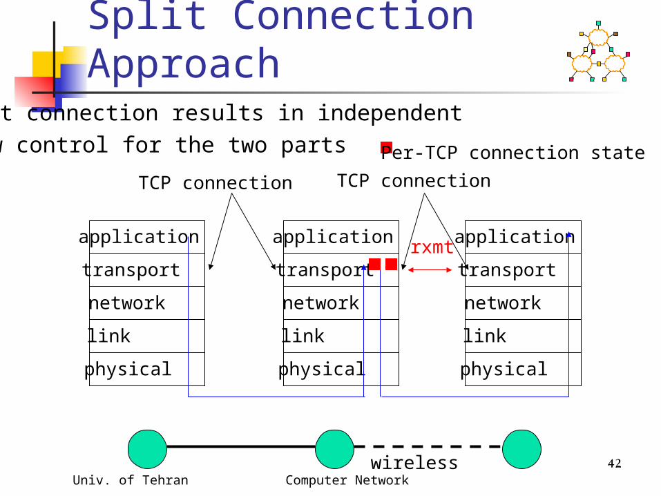
Per-TCP connection state
TCP connection TCP connection
Split connection results in independent flow control for the two parts

Univ. of Tehran Computer Network 43
Split Connection Approach : Other Variations
Asymmetric transport protocol (Mobile-TCP)Low overhead protocol at wireless hosts, and higher overhead protocol at wired hosts smaller headers used on wireless hop (header
compression) simpler flow control - on/off for MH to BS
transfer MH only does error detection, BS does error
correction too No congestion control over wireless hop
Univ. of Tehran Computer Network 44
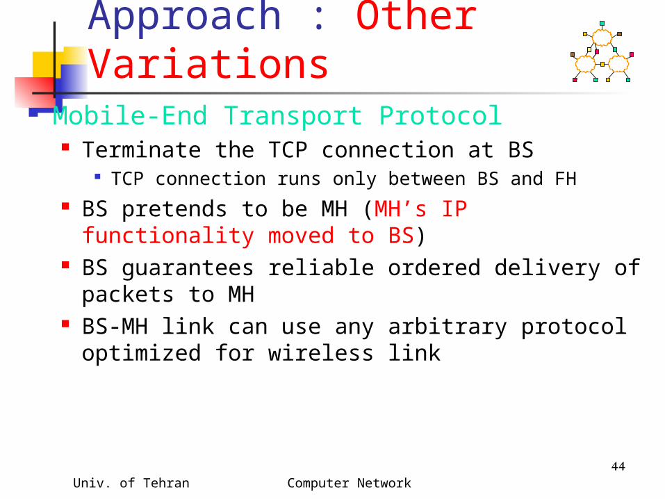
Split Connection Approach : Other Variations
Mobile-End Transport Protocol Terminate the TCP connection at BS
TCP connection runs only between BS and FH BS pretends to be MH (MH’s IP functionality
moved to BS) BS guarantees reliable ordered delivery of
packets to MH BS-MH link can use any arbitrary protocol
optimized for wireless link
Univ. of Tehran Computer Network 45
Split Connection Approach :
Hides transmission errors from sender
Primary responsibility at base station
If specialized transport protocol used on wireless, then wireless host also needs modification
In case of Mobile host, the state of BS can be transferred.
Univ. of Tehran Computer Network 46
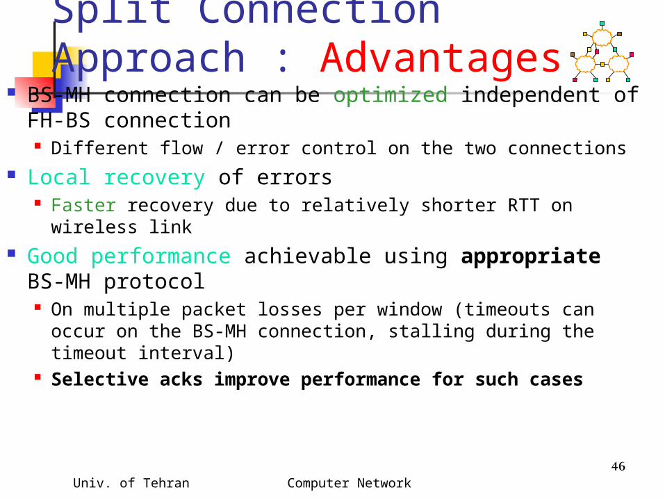
Split Connection Approach : Advantages
BS-MH connection can be optimized independent of FH-BS connection Different flow / error control on the two connections
Local recovery of errors Faster recovery due to relatively shorter RTT on wireless
link Good performance achievable using appropriate
BS-MH protocol On multiple packet losses per window (timeouts can occur
on the BS-MH connection, stalling during the timeout interval)
Selective acks improve performance for such cases

Univ. of Tehran Computer Network 47
Split Connection Approach : Disadvantages
End-to-end semantics violated ack may be delivered to sender, before
data delivered to the receiver May not be a problem for applications
that do not rely on TCP for the end-to-end semantics
FH MHBS
40
39
3738
3640

Univ. of Tehran Computer Network 48
Split Connection Approach : Disadvantages
BS retains hard stateBS failure can result in loss of data (unreliability) If BS fails, packet 40 will be lost Because it is ack’d to sender, the sender does not
buffer 40
FH MHBS
40
39
3738
3640
Univ. of Tehran Computer Network 49
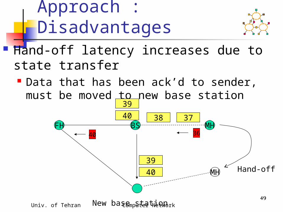
Split Connection Approach : Disadvantages
Hand-off latency increases due to state transfer Data that has been ack’d to sender, must be
moved to new base station
FH MHBS
40
39
3738
3640
MH
New base station
Hand-off
40
39

Univ. of Tehran Computer Network 50
Split Connection Approach : Disadvantages
Buffer space needed at BS for each TCP connection BS buffers tend to get full, when wireless
link slower. Window on BS-MH connection reduced
in response to errors may not be an issue for wireless links with
small delay-bw product

Univ. of Tehran Computer Network 51
Split Connection Approach : Disadvantages
Extra copying of data at BS One for FH-BS socket buffer and one for
BS-MH. increases end-to-end latency May not be useful if data and acks traverse
different paths (both do not go through the base station)
Example: data on a satellite wireless hop, acks on a dial-up channel
FH MH
data
ack

Univ. of Tehran Computer Network 52
Various Schemes Link layer mechanisms Split connection approach TCP-Aware link layer TCP-Unaware approximation of TCP-
aware link layer Explicit notification
Receiver-based discrimination Sender-based discrimination

Univ. of Tehran Computer Network 53
Snoop Protocol Buffers data packets at the base station BS
to allow link layer retransmission soft state at base station, instead of hard state
When dupacks received by BS from MH, retransmit on wireless link, if packet present in buffer
Prevents fast retransmit at TCP sender FH by dropping the dupacks at BS
Hides wireless losses from the sender Requires modification to only BS (network-
centric approach)

Univ. of Tehran Computer Network 54
Snoop Protocol
FH MHBSwireless
physical
link
network
transport
application
physical
link
network
transport
application
physical
link
network
transport
application
rxmt
Per TCP-connection state
TCP connection

Univ. of Tehran Computer Network 55
Snoop : Example
FH MHBS
40 39 3738
3634
Example assumes delayed ack - every other packet ack’d
36
37
38
35 TCP statemaintained at
link layer

Univ. of Tehran Computer Network 56
Snoop : Example
41 40 3839
3634
36
37
38
35 39

Univ. of Tehran Computer Network 57
Snoop : Example
42 41 3940
36
Duplicate acks are not delayed
36
dupack
37
38
39
40

Univ. of Tehran Computer Network 58
Snoop : Example
40
363636
Duplicate acks
4143 42
37
38
39
40
41
Univ. of Tehran Computer Network 59
Snoop : Example
FH MHBS
41
3636
3744 43
36
37
38
39
40
41
42
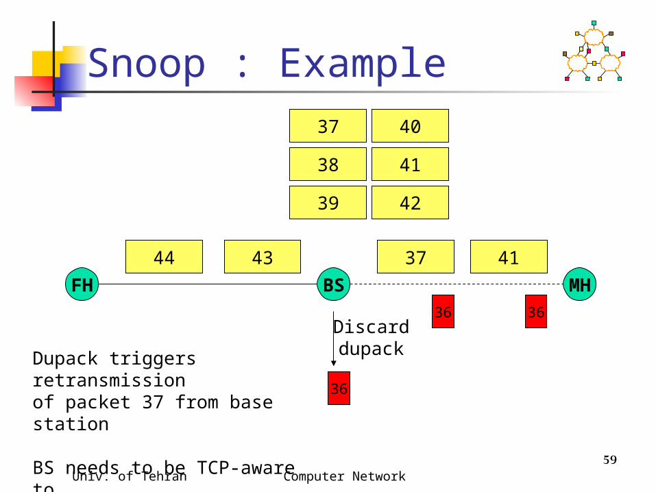
DiscarddupackDupack triggers retransmission
of packet 37 from base station BS needs to be TCP-aware tobe able to interpret TCP headers

Univ. of Tehran Computer Network 60
Snoop : Example
37
36
36
4245 44
36
37
38
39
40
41
42
43
36

Univ. of Tehran Computer Network 61
Snoop : Example
42
36
36
4346 45
36
37
38
39
40
41
42
43
41
36
44
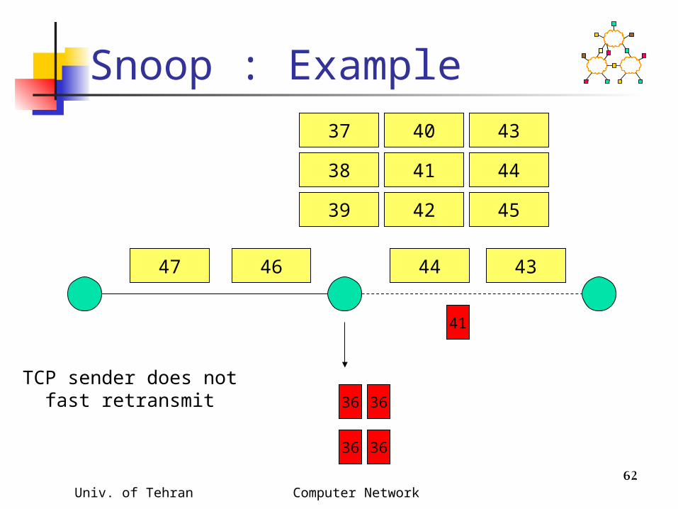
TCP sender does notfast retransmit
Univ. of Tehran Computer Network 62
Snoop : Example
43
3636
4447 46
36
37
38
39
40
41
42
43
41
36
44
TCP sender does notfast retransmit
45

Univ. of Tehran Computer Network 63
Snoop : Example
FH MHBS
44
3636
4548 47
36
42
43
41
36
44
45
43
46
Univ. of Tehran Computer Network 64
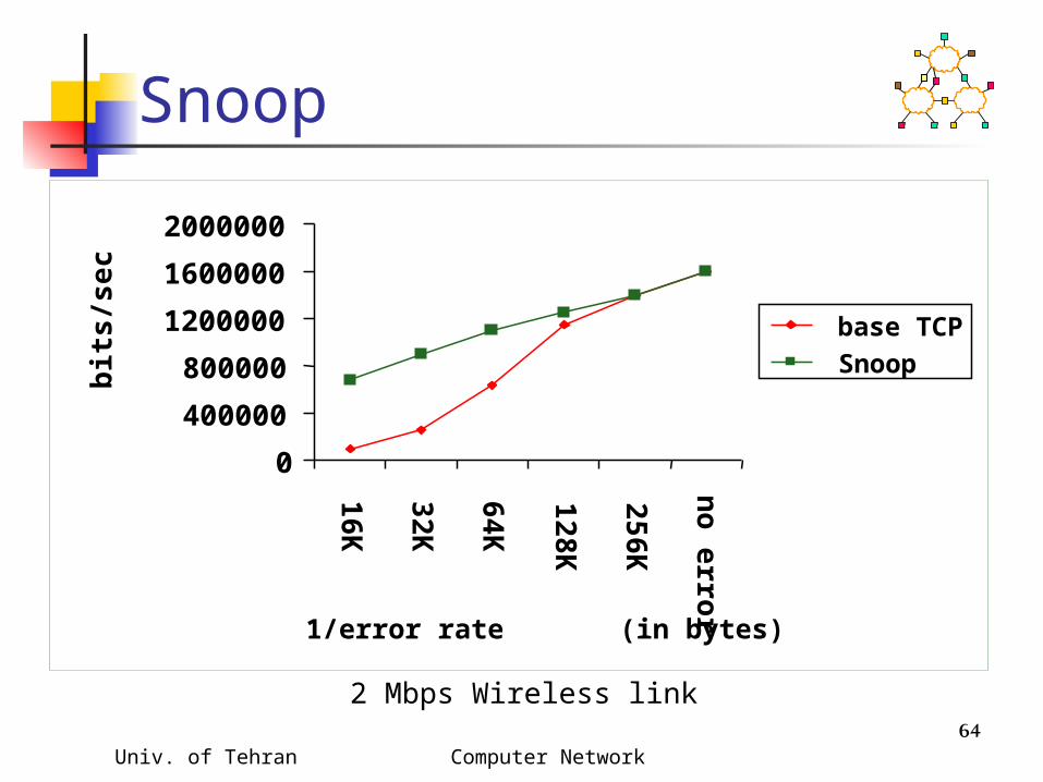
Snoop
2 Mbps Wireless link
0
400000
800000
1200000
1600000
2000000
16K
32K
64K
128
K
256
K
no
erro
r
1/error rate (in bytes)
bit
s/s
ec
base TCP
Snoop

Univ. of Tehran Computer Network 65
Snoop: When Beneficial? Snoop prevents fast retransmit
despite transmission errors, and out-of-order delivery on the wireless link
If wireless link level delay-bandwidth product is less than 4 packets, a simple (TCP-unaware) link level retransmission scheme can suffice Since delay-bandwidth product is small,
the retransmission scheme can deliver the lost packet without resulting in 3 dupacks from the TCP receiver
Univ. of Tehran Computer Network 66
Snoop: Advantages High throughput can be achieved
performance further improved using selective acks
Local recovery from wireless losses Fast retransmit not triggered at sender
despite out-of-order link layer delivery End-to-end semantics retained Soft state at base station
loss of the soft state affects performance, but not correctness
Univ. of Tehran Computer Network 67
Snoop: Disadvantages Link layer at base station needs to be TCP-
aware Not useful if TCP headers are encrypted (IPsec)
Cannot be used if TCP data and TCP acks traverse different paths (both do not go through the base station)
Snoop hides wireless losses from the sender But sender’s RTT estimates may be larger in
presence of errors Larger RTO results in slower response for
congestion losses

Univ. of Tehran Computer Network 68
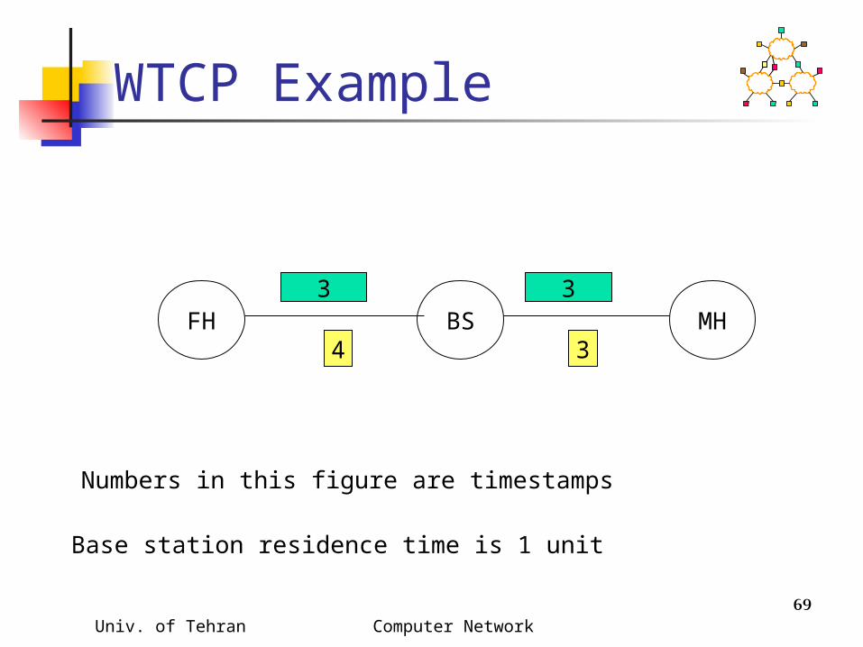
WTCP Protocol WTCP performs local recovery, similar to
Snoop In addition, WTCP uses the timestamp
option to estimate RTT The base station adds base station
residence time to the timestamp when processing an ack received from the wireless host
Sender’s RTT estimate not affected by retransmissions on wireless link
Univ. of Tehran Computer Network 69
WTCP Example
FH BS MH3 3
34
Numbers in this figure are timestamps
Base station residence time is 1 unit

Univ. of Tehran Computer Network 70
WTCP : Disadvantages Requires use of the timestamp option May be useful only if retransmission times are large
link stays in bad state for a long time link frequently enters a bad state link delay large
WTCP does not account for congestion on wireless hop assumes that all delay at base station is due to queuing
and retransmissions will not work for shared wireless LAN, where delays also
incurred due to contention with other transmitters

Univ. of Tehran Computer Network 71
Various Schemes Link layer mechanisms Split connection approach TCP-Aware link layer TCP-Unaware approximation of TCP-
aware link layer Explicit notification
Receiver-based discrimination Sender-based discrimination

Univ. of Tehran Computer Network 72
Delayed Dupacks Protocol Attempts to imitate Snoop, without making the
base station TCP-aware Snoop implements two features at the base
station link layer retransmission reducing interference between TCP and link layer
retransmissions (by dropping dupacks) Delayed Dupacks implements the same two
features at BS : link layer retransmission at MH : reducing interference between TCP and link
layer retransmissions (by delaying dupacks)

Univ. of Tehran Computer Network 73
Delayed Dupacks Protocol
wireless
physical
link
network
transport
application
physical
link
network
transport
application
physical
link
network
transport
application
rxmt
TCP connection
Link layer state
Univ. of Tehran Computer Network 74
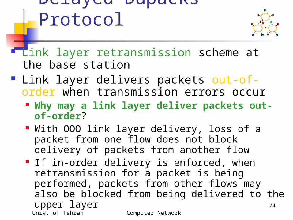
Delayed Dupacks Protocol
Link layer retransmission scheme at the base station
Link layer delivers packets out-of-order when transmission errors occur Why may a link layer deliver packets out-of-
order? With OOO link layer delivery, loss of a packet from
one flow does not block delivery of packets from another flow
If in-order delivery is enforced, when retransmission for a packet is being performed, packets from other flows may also be blocked from being delivered to the upper layer

Univ. of Tehran Computer Network 75
Delayed Dupacks Protocol TCP receiver delays dupacks (third and
subsequent) for interval D, when out-of-order packets received
Dupack delay intended to give link level retransmit time to succeed
Benefit: Delayed dupacks can result in recovery from a transmission loss without triggering a response from the TCP sender
Disadvantage: Recovery from congestion losses delayed

Univ. of Tehran Computer Network 76
Delayed Dupacks : Example
40 39 3738
3634
Example assumes delayed ack - every other packet ack’d
Link layer acks are not shown
36
37
38
35
Link layer state
Univ. of Tehran Computer Network 77
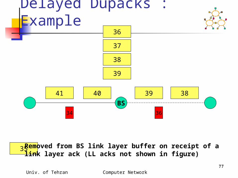
Delayed Dupacks : Example
BS
41 40 3839
3634
36
37
38
39
35 Removed from BS link layer buffer on receipt of alink layer ack (LL acks not shown in figure)

Univ. of Tehran Computer Network 78
Delayed Dupacks : Example
42 41 3940
36
Duplicate acks are not delayed
36
dupack
37
38
39
40

Univ. of Tehran Computer Network 79
Delayed Dupacks : Example
40
363636
Duplicate acks
4143 42
37
38
39
40
41
Original ack

Univ. of Tehran Computer Network 80
Delayed Dupacks : Example
41
3636
3744 43
36
37
39
40
41
42
Base station forwards dupacks
dupack dupacksDelayeddupack

Univ. of Tehran Computer Network 81
Delayed Dupacks : Example
37
3636
4245 44
36
37
40
41
42
36dupacks
Delayed dupacks
43

Univ. of Tehran Computer Network 82
Delayed Dupacks : Example
424346 45
36
37
41
42
43
41
TCP sender does notfast retransmit
44
Delayed dupacks arediscarded if lost
packet received beforedelay D expires
Univ. of Tehran Computer Network 83
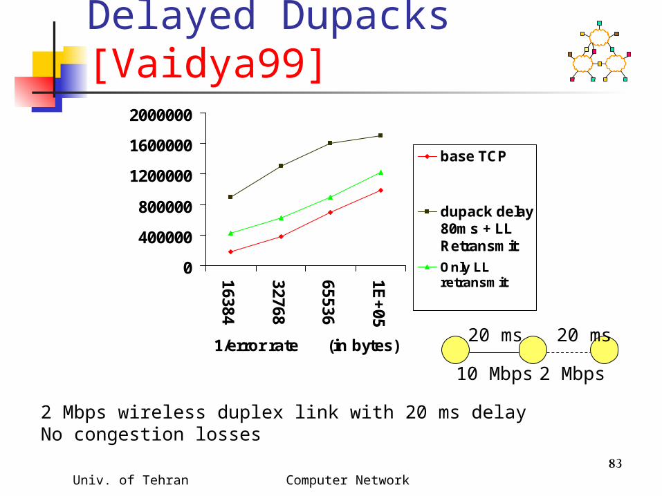
Delayed Dupacks [Vaidya99]
0
400000
800000
1200000
1600000
2000000
16384
32768
65536
1E+
05
1/error rate (in bytes)
base TCP
dupack delay80ms + LLRetransmit
Only LLretransmit
2 Mbps wireless duplex link with 20 ms delayNo congestion losses
20 ms 20 ms
10 Mbps 2 Mbps

Univ. of Tehran Computer Network 84
Delayed Dupacks [Vaidya99]
020000400006000080000
100000120000140000160000
16
38
4
32
76
8
65
53
6
1E
+0
5
1/error rate (in bytes)
base TCP
dupack delay80ms + LLRetransmit
Only LLretransmit
5% packet loss due to congestion
20 ms 20 ms
10 Mbps 2 Mbps

Univ. of Tehran Computer Network 85
Delayed Dupacks Scheme : Advantages
Link layer need not be TCP-aware Can be used even if TCP headers are
encrypted Works well for relatively small
wireless RTT (compared to end-to-end RTT)
relatively small delay D sufficient in such cases

Univ. of Tehran Computer Network 86
Delayed Dupacks Scheme : Disadvantages
Right value of dupack delay D dependent on the wireless link properties
Mechanisms to automatically choose D needed
Delays dupacks for congestion losses too, delaying congestion loss recovery

Univ. of Tehran Computer Network 87
Various Schemes Link-layer retransmissions Split connection approach TCP-Aware link layer TCP-Unaware approximation of TCP-
aware link layer Explicit notification
Receiver-based discrimination Sender-based discrimination
Univ. of Tehran Computer Network 88
Explicit Notification Schemes
Approximate Ideal TCP behavior: Ideally, the TCP sender should simply retransmit a packet lost due to transmission errors, without taking any congestion control actions
A wireless node somehow determines that packets are lost due to errors and informs the sender using an explicit notification
Sender, on receiving the notification, does not reduce congestion window, but retransmits lost packet

Univ. of Tehran Computer Network 89
Explicit Notification Schemes
Motivated by the Explicit Congestion Notification (ECN) proposals [Floyd94]
Variations proposed in literature differ in who sends explicit notification how they know to send the explicit
notification what the sender does on receiving the
notification

Univ. of Tehran Computer Network 90
Space Communication Protocol Standards-Transport Protocol (SCPS-TP)
Satellite
Ground station
wireless
TCP destinations
Univ. of Tehran Computer Network 91
SCPS-TP Protocol The receiving ground station keeps track of how many
packets with errors are received (their checksums failed)
When the error rate exceeds a threshold, the ground station sends corruption experienced messages to destinations of recent error-free TCP packets
destinations are cached The TCP destinations tag acks with corruption-
experienced bit TCP sender, after receiving an ack with corruption-
experienced bit, does not back off until it receives an ack without that bit (even if timeout or fast retransmit occurs)
Univ. of Tehran Computer Network 92
Explicit Loss Notification when MH is the TCP sender
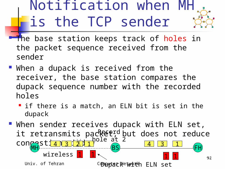
The base station keeps track of holes in the packet sequence received from the sender
When a dupack is received from the receiver, the base station compares the dupack sequence number with the recorded holes if there is a match, an ELN bit is set in the dupack
When sender receives dupack with ELN set, it retransmits packet, but does not reduce congestion window
MH FHBS4 3 2 1 134
wireless
Recordhole at 2
111 1
Dupack with ELN set

Univ. of Tehran Computer Network 93
Explicit Bad State Notification when MH is TCP receiver
Base station attempts to deliver packets to the MH using a link layer retransmission scheme
If packet cannot be delivered using a small number of retransmissions, BS sends a Explicit Bad State Notification (EBSN) message to TCP sender
When TCP sender receives EBSN, it resets its timer timeout delayed, when wireless channel in bad
state

Univ. of Tehran Computer Network 94
Partial Ack Protocols Send two types of
acknowledgements A partial acknowledgement informs
the sender that a packet was received by an intermediate host (typically, base station)
Normal TCP cumulative ack needed by the sender for reliability purposes

Univ. of Tehran Computer Network 95
Partial Ack Protocols When a packet for which a partial ack is
received is detected to be lost, the sender does not reduce its congestion window loss assumed to be due to wireless errors37
36
Partial ack
37
Cumulative ack
Univ. of Tehran Computer Network 96
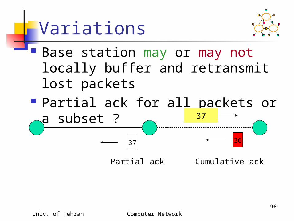
Variations Base station may or may not locally
buffer and retransmit lost packets Partial ack for all packets or a subset
?37
36
Partial ack
37
Cumulative ack

Univ. of Tehran Computer Network 97
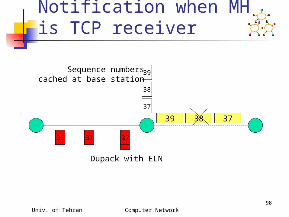
Explicit Loss Notification when MH is TCP receiver
Attempts to approximate hypothetical ELN proposed in [Balakrishnan96] for the case when MH is receiver
Caches TCP sequence numbers at base station, similar to Snoop. But does not cache data packets, unlike Snoop.
Duplicate acks are tagged with ELN bit before being forwarded to sender if sequence number for the lost packet is cached at the base station
Sender takes appropriate action on receiving ELN
Univ. of Tehran Computer Network 98
Explicit Loss Notification when MH is TCP receiver
37
36
37
3839
39
38
Sequence numberscached at base station
37 37
Dupack with ELN
Univ. of Tehran Computer Network 99
Various Schemes Link-layer retransmissions Split connection approach TCP-Aware link layer TCP-Unaware approximation of TCP-
aware link layer Explicit notification
Receiver-based discrimination Sender-based discrimination

Univ. of Tehran Computer Network 100
Receiver-Based Scheme MH is TCP receiver which uses a
heuristic to guess cause of packet loss When receiver believes that packet
loss is due to errors, it sends a notification to the TCP sender
TCP sender, on receiving the notification, retransmits the lost packet, but does not reduce congestion window

Univ. of Tehran Computer Network 101
Receiver-Based Scheme Packet loss due to congestion
FH MHBS
1012 11
FH MHBS
11
1012
T
Congestion loss

Univ. of Tehran Computer Network 102
Receiver-Based Scheme Packet loss due to transmission
error
FH MHBS
1012 11
FH MHBS
101112Error loss
2 T
Univ. of Tehran Computer Network 103
Receiver-Based Scheme
Receiver uses the inter-arrival time between consecutively received packets to guess the cause of a packet loss
On determining a packet loss as being due to errors, the receiver may tag corresponding dupacks with an ELN
bit, or send an explicit notification to sender
Univ. of Tehran Computer Network 104
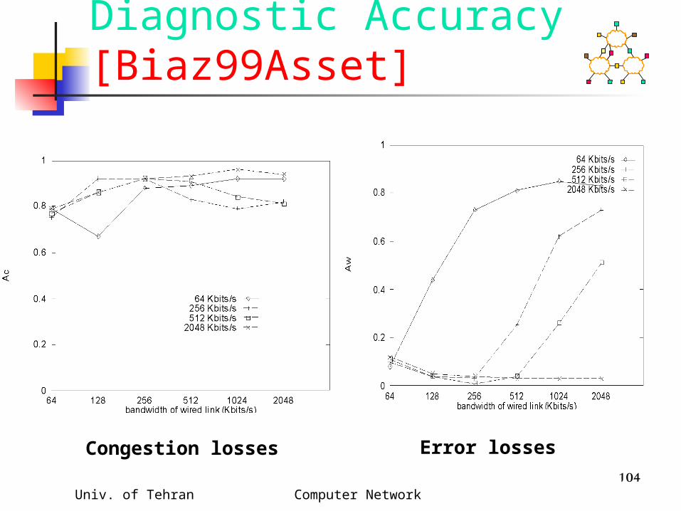
Diagnostic Accuracy [Biaz99Asset]
Congestion losses Error losses

Univ. of Tehran Computer Network 105
Receiver-Based Scheme : Disadvantages
Disadvantages: Limited applicability
Advantages: Can be implemented without modifying
the base station (an “end-to-end” scheme)
May be used despite encryption, or if data & acks traverse different paths multiple connections on the link will make inter-packet delays variable

Univ. of Tehran Computer Network 106
Various Schemes Link-layer retransmissions Split connection approach TCP-Aware link layer TCP-Unaware approximation of TCP-
aware link layer Explicit notification
Receiver-based discrimination Sender-based discrimination
Univ. of Tehran Computer Network 107
Sender-Based Discrimination Scheme
Sender can attempt to determine cause of a packet loss
If packet loss determined to be due to errors, do not reduce congestion window
Sender can only use statistics based on round-trip times, window sizes, and loss pattern unless network provides more information
(example: explicit loss notification)

Univ. of Tehran Computer Network 108
Heuristics for Congestion Avoidance
load
RTT
throughput
knee
cliff
load

Univ. of Tehran Computer Network 109
Heuristics for Congestion Avoidance
Define condition C as a function of congestion window size and observed RTTs
Condition C evaluated when a new RTT is calculated condition C typically evaluates to 2 or 3
possible values for now assume 2 values: TRUE or FALSE
If (C == True) reduce congestion window Several proposals for condition C

Univ. of Tehran Computer Network 110
Heuristics for Congestion Avoidance
Normalized Delay Gradient [jain89]
r = [RTT(i)-RTT(i-1)] / [RTT(i)+RTT(i-1)]
w = [W(i)-W(i-1)] / [W(i)+W(i-1)]
Condition C = (r/w > 0)

Univ. of Tehran Computer Network 111
Heuristics for Congestion Avoidance
Normalized Throughput Gradient [Wang91]Throughput gradient
TG(i) = [T(i) - T(i-1) ] / [ W(i)-W(i-1)]
Normalized Throughout GradientNTG = TG(i) / TG(1)
Condition C = (NTG < 0.5)
Univ. of Tehran Computer Network 112
Heuristics for Congestion Avoidance
TCP Vegas [Brakmo94]expected throughput ET = W(i) / RTTminactual throughput AT = W(i) / RTT(i)Condition C = ( ET-AT > beta)

Univ. of Tehran Computer Network 113
Sender-Based Heuristics Record latest value evaluated for
condition C When a packet loss is detected
if last evaluation of C is TRUE, assume packet loss is due to congestion
else assume that packet loss is due to transmission errors
If packet loss determined to be due to errors, do not reduce congestion window

Univ. of Tehran Computer Network 114
Sender-Based Heuristics : Disadvantage
Does not work quite well enough as yet !!
Reasons Statistics collected by the sender
garbled by other traffic on the network Not much correlation between observed
short-term statistics, and onset of congestion
Univ. of Tehran Computer Network 115
Sender-Based Heuristics : Advantages
Only sender needs to be modified Needs further investigation to
develop better heuristics investigate longer-term heuristics
Univ. of Tehran Computer Network 116
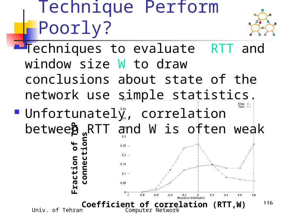
Why do Statistical Technique Perform Poorly?
Techniques to evaluate RTT and window size W to draw conclusions about state of the network use simple statistics.
Unfortunately, correlation between RTT and W is often weak
Fra
ctio
n o
f T
CP
c
on
ne
cti
on
s
Coefficient of correlation (RTT,W)

Univ. of Tehran Computer Network 117
Statistical TechniquesFuture Work Other statistical measures ? Mechanisms that achieve good TCP
throughput despite not-too-good diagnostic accuracy

Univ. of Tehran Computer Network 118
Transmission ErrorsSummary
Many techniques have been proposed, and several approaches perform well in many environments
Recommendation: Prefer end-to-end techniques End-to-end techniques are those which
do not require TCP-Specific help from lower layers Lower layers may help improve TCP performance
without taking TCP-specific actions. Examples: Semi-reliable link level retransmission schemes Explicit notification

Univ. of Tehran Computer Network 119
TCP over Satellite Geostationary Earth Orbit (GEO) Satellite
long latency transmission errors or channel unavailability
Low Earth Orbit (LEO) Satellite relatively smaller delays delays more variable
Problems? Long delay Large delay-bandwidth products Transmission errors

Univ. of Tehran Computer Network 120
Improving TCP-over-Satellite
Larger congestion window (window scale option) maximum window size up to 230
Acknowledge every packet (do not delay acks)
Selective acks fast recovery can only recover one
packet loss per RTT SACKS allow multiple packet recovery per
RTT
Univ. of Tehran Computer Network 121
Larger Initial Window Allows initial window size of cwnd to
be up to approximately 4 Kbyte Larger initial window results in faster
window growth during slow start avoids wait for delayed ack timers
(which will occur with cwnd = 1 MSS) larger initial window requires fewer
RTTs to reach ssthresh

Univ. of Tehran Computer Network 122
Byte Counting Increase window by number of new
bytes ack’d in an acknowledgement, instead of 1 MSS per ack
Speeds up window growth despite delayed or lost acks
Need to reduce bursts from sender limiting size of window growth per ack rate control
Univ. of Tehran Computer Network 123
Space Communications Protocol Standard-Transport Protocol (SCPS-TP) [Durst96]
Sender makes default assumption about source of packet loss default assumption can be set by
network manager on a per-route basis default assumption can be changed due
to explicit feedback from the network Congestion control algorithm derived
from TCP-Vegas, to bound window growth, to reduce congestion-induced losses
Univ. of Tehran Computer Network 124
Protocol (SCPS-TP) During link outage, TCP sender freezes itself, and
resumes when link is restored outage assumed to occur in both directions
simultaneously ground station can detect outage of incoming link (for
instance, by low signal levels), and infers outage of outgoing link
ground stations provide link outage information to any sender that attempts to send packets on the outgoing link
sender does not unnecessarily timeout or retransmit until it is informed that link has recovered
Selective acknowledgement protocol to recover losses quickly
Univ. of Tehran Computer Network 125
Satellite Transport Protocol (STP)
Uses split connection approach Protocol on satellite channel different
from TCP selective negative acks when receiver
detects losses no retransmission timer transmitter periodically requests
receiver to ack received data reduces reverse channel bandwidth
usage when losses are rare

Univ. of Tehran Computer Network 126
Early Acks Spoofing
Ground station acks packets Should take responsibility for delivering packets Early acks from ground station result in faster
congestion window growth ACKprime approach [Scott98]
Acks from ground station only used to grow congestion window
Reliable delivery assumed only on reception of an ack from the receiver
this is similar to the partial ack approach [Biaz97]
Univ. of Tehran Computer Network 127
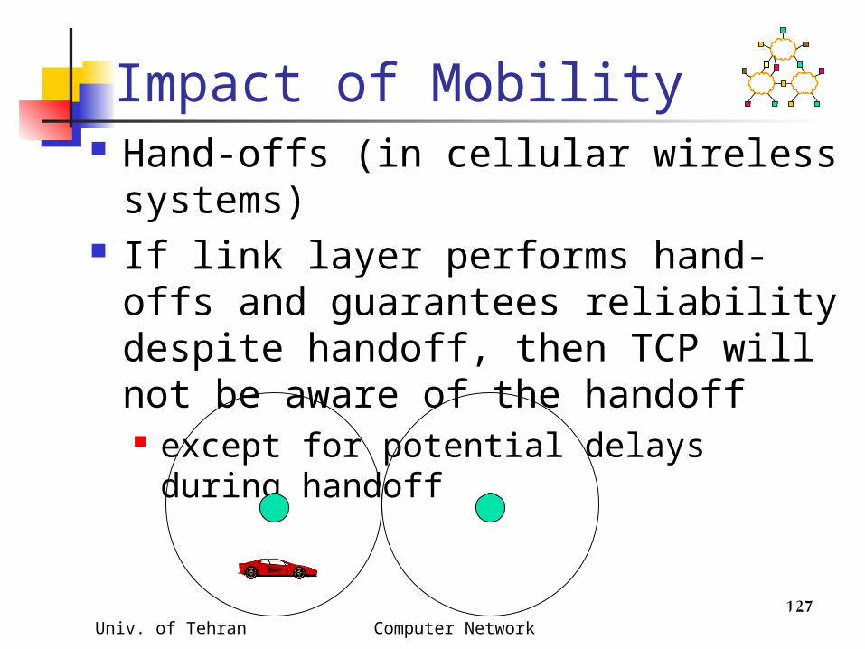
Impact of Mobility Hand-offs (in cellular wireless
systems) If link layer performs hand-offs and
guarantees reliability despite handoff, then TCP will not be aware of the handoff except for potential delays during
handoff
Univ. of Tehran Computer Network 128
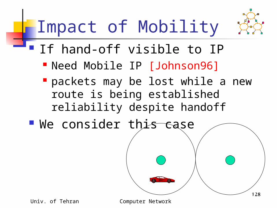
Impact of Mobility If hand-off visible to IP
Need Mobile IP [Johnson96] packets may be lost while a new route
is being established reliability despite handoff
We consider this case

Univ. of Tehran Computer Network 129
Improving TCP in Presence of Mobility
Hide mobility from the TCP sender Mobile IP
Make TCP adaptive to mobility

Univ. of Tehran Computer Network 130
Example Hand-Off Procedure
1. Each base station periodically transmits beacon2. Mobile host, on hearing stronger beacon from a new
BS, sends it a greeting changes routing tables to make new BS its default gateway sends new BS identity of the old BS
OldBS
NewBS
MH
2
1
3
4
5,6
7
Univ. of Tehran Computer Network 131
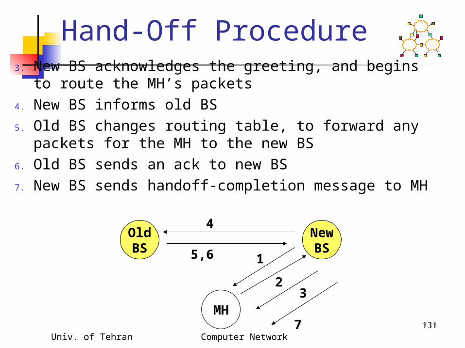
Hand-Off Procedure3. New BS acknowledges the greeting, and begins to
route the MH’s packets4. New BS informs old BS5. Old BS changes routing table, to forward any
packets for the MH to the new BS6. Old BS sends an ack to new BS7. New BS sends handoff-completion message to MH
OldBS
NewBS
MH
2
1
3
4
5,6
7

Univ. of Tehran Computer Network 132
Hand-off Hand-offs may result in temporary
loss of route to MH with non-overlapping cells, it may be a
while before the mobile host receives a beacon from the new BS
While routes are being reestablished during handoff, MH and old BS may attempt to send packets to each other, resulting in loss of packets

Univ. of Tehran Computer Network 133
Using Fast Retransmits to Recover from Timeouts during Handoff [Caceres95]
During the long delay for a handoff to complete, a whole window worth of data may be lost
After handoff is complete, acks are not received by the TCP sender
Sender eventually times out, and retransmits If handoff still not complete, another timeout
will occur Performance penalty
Time wasted until timeout occurs Window shrunk after timeout

Univ. of Tehran Computer Network 134
0-second Rendezvous Delay : Beacon arrives as soon as cell boundary crossed
Lasttimedtransmit
Cell crossing+ beaconarrives
Handoff completeRoutes updated
Retransmissiontimeout
0 0.15 0.8 sec
1.0
Packet loss Idle sender

Univ. of Tehran Computer Network 135
1-second Rendezvous Delay : Beacon arrives 1 second after cell boundary crossed
Lasttimedtransmit
0 0.8
2.0
Timeout 1
Cell crossing
Packet loss
Retransmissiontimeout 2
Handoffcomplete
Beacon arrives
1.0
1.0 1.15
Idle sender
2.8 sec
Univ. of Tehran Computer Network 136
Performance [Caceres95]Four environments1. No moves2. Moves (once per 8 sec) between overlapping
cells3. Moves between non-overlapping cells, 0 sec
delay4. Moves between non-overlapping cells, 1 sec
delay
Experiments using 2 Mbps WaveLan

Univ. of Tehran Computer Network 137
TCP Performance
1600 1510 14001100
0200400600800
10001200140016001800
No move
s
overla
pping
cells
non-o
verla
p/0 d
elay
non-o
verla
p/1 s
ec.
Kbit/sec
Univ. of Tehran Computer Network 138
TCP Performance Degradation in case 2 (overlapping
cells) is due to encapsulation and forwarding delay during handoff
Additional degradation in cases 3 and 4 due to packet loss and idle time at sender

Univ. of Tehran Computer Network 139
Mitigation Using Fast Retransmit
When MH is the TCP receiver: after handoff is complete, it sends 3 dupacks to the sender this triggers fast retransmit at the
sender instead of dupacks, a special notification
could also be sent When MH is the TCP sender: invoke
fast retransmit after completion of handoff
Univ. of Tehran Computer Network 140
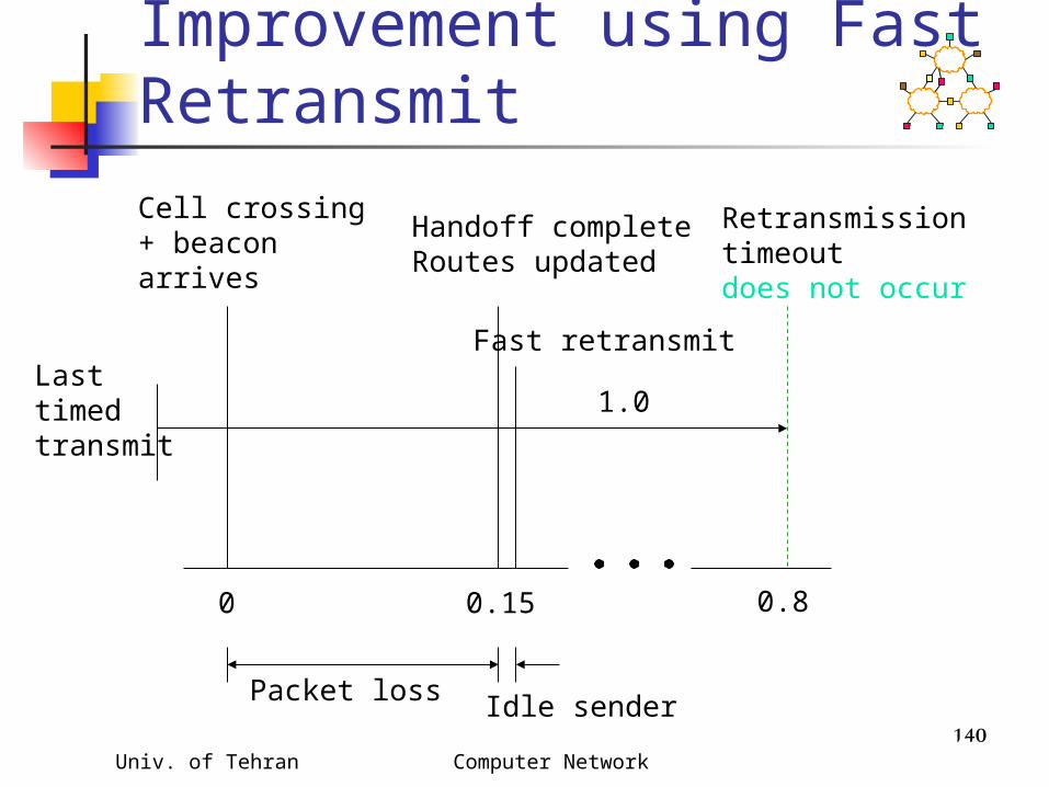
0-second Rendezvous DelayImprovement using Fast Retransmit
Lasttimedtransmit
Cell crossing+ beaconarrives
Handoff completeRoutes updated
Retransmissiontimeoutdoes not occur
0 0.15 0.8
1.0
Packet loss
Fast retransmit
Idle sender
Univ. of Tehran Computer Network 141
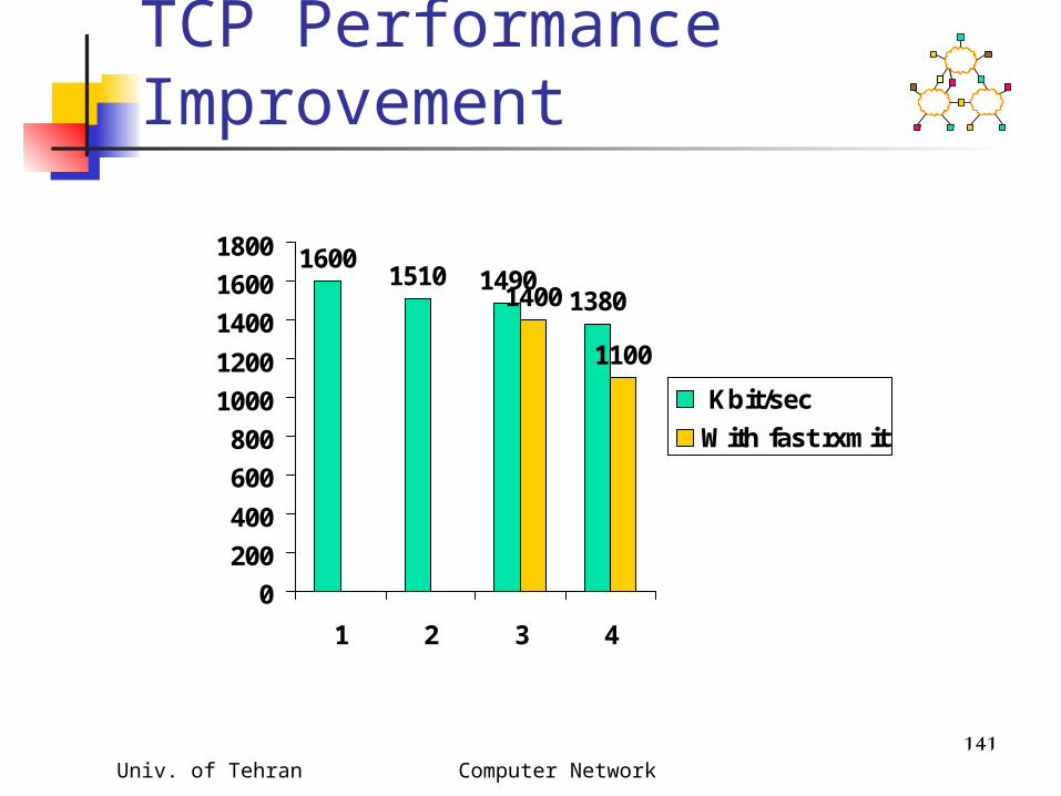
TCP Performance Improvement
16001510 1490
13801400
1100
0
200
400
600
800
1000
1200
1400
1600
1800
1 2 3 4
Kbit/sec
With fast rxmit

Univ. of Tehran Computer Network 142
TCP Performance Improvement
No change in cases 1 and 2, as expected
Improvement for non-overlapping cells
Some degradation remains in case 3 and 4 fast retransmit reduces congestion window
Univ. of Tehran Computer Network 143
Improving Performance by Smooth Handoffs [Caceres95]
Provide sufficient overlap between cells to avoid packet loss
Buffer packets at BS Discard the packets after a short
interval If handoff occurs before the interval
expires, forward the packets to the new base station
Prevents packet loss on handoff
Univ. of Tehran Computer Network 144
M-TCP [Brown97] In the fast retransmit scheme
[Caceres95] sender starts transmitting soon after
handoff BUT congestion window shrinks
M-TCP attempts to avoid shrinkage in the congestion window

Univ. of Tehran Computer Network 145
M-TCP UsesTCP Persist Mode
When a new ack is received with receiver’s advertised window = 0, the sender enters persist mode
Sender does not send any data in persist mode except when persist timer goes off
When a positive window advertisement is received, sender exits persist mode
On exiting persist mode, RTO and cwnd are same as before the persist mode

Univ. of Tehran Computer Network 146
M-TCP Similar to the split connection approach,
M-TCP splits one TCP connection into two logical parts the two parts have independent flow
control as in I-TCP The BS does not send an ack to MH,
unless BS has received an ack from MH maintains end-to-end semantics
BS withholds ack for the last byte ack’d by MH
FH MHBS
Ack 1000Ack 999

Univ. of Tehran Computer Network 147
M-TCP Withheld ack sent with window
advertisement = 0, if MH moves away (handoff in progress)
Sender FH put into persist mode during handoff
Sender exits persist mode after handoff, and starts sending packets using same cwnd as before handoff
FH MHBS
Univ. of Tehran Computer Network 148
M-TCP The last ack is not withheld, if BS
does not expect any other ack from the MH this happens when the BS has no other
unack’d data buffered locally this is required to prevent a sender
timeout at the end of a transfer (or end of a burst of data)
Univ. of Tehran Computer Network 149
M-TCP Avoids reduction of congestion window due
to handoff, unlike the fast retransmit scheme simulation-based performance results look good
Important Question unanswered : Is not reducing the window a good idea?When host moves, route changes, and new route may be more congested than before.It is not obvious that starting full speed after handoff is right.

Univ. of Tehran Computer Network 150
FreezeTCP [Goff99] M-TCP needs help from base station
Base station withholds ack for one byte The base station uses this ack to send a
zero window advertisement when a mobile host moves to another cell
FreezeTCP requires the receiver to send zero window advertisement (ZWA)FH MHBS
MobileTCP receiver

Univ. of Tehran Computer Network 151
FreezeTCP [Goff99] TCP receiver determines if a handoff is
about to happen determination may be based on signal strength
Ideally, receiver should attempt to send ZWA 1 RTT before handoff
Receiver sends 3 dupacks when route is reestablished
No help needed from the base station an end-to-end enhancement
FH MHBS
MobileTCP receiver

Univ. of Tehran Computer Network 152
Using Multicast to Improve Handoffs [Ghai94,Seshan96]
Define a group of base stations including current cell of a mobile host cells that the mobile host is likely to visit
next Address packets destined to the mobile
host to the group Only one base station transmits the
packets to the mobile host if rest of them buffer the packets, then
packet loss minimized on handoff

Univ. of Tehran Computer Network 153
Using Multicast to Improve Handoffs
Static group definition [Ghai94] groups can be defined taking physical
topology into account static definition may not take individual
user mobility pattern into account Dynamic group definition [Seshan96]
implemented using IP multicast groups each user’s group can be different overhead of updating the multicast groups
is a concern with a large scale deployment
Univ. of Tehran Computer Network 154
Using Multicast to Improve Handoffs
Buffering at multiple base stations incurs memory overhead
Trade-off between buffering overhead and packet loss
Buffer requirement can be reduced by starting buffering only when a mobile host is likely to leave current cell soon
Univ. of Tehran Computer Network 155
Issues for Further Investigation
Univ. of Tehran Computer Network 156
Link Layer Protocols “Pure” link layer designs that support
higher transport performance some recent work in this area as noted
earlier Identifying scenarios where link layer
solutions are inadequate If TCP-awareness is absolutely
needed, provide an interface that can be used by other transport protocols too

Univ. of Tehran Computer Network 157
End-to-End Techniques Existing techniques typically require
cooperation from intermediate nodes. Such techniques often not applicable
encrypted TCP headers TCP data and acks do not go through same
base station End-to-end techniques would rely on
information available only at end nodes Harder to design due to lack of complete
information about errors Explicit Notifications may make that easier

Univ. of Tehran Computer Network 158
Impact of Congestion Losses
Past work typically evaluates performance in absence of congestion
Relative performance improvement may change substantially when congestion occurs performance improvement may reduce
if congestion is dominant, or if RTO becomes larger due to wireless errors
Univ. of Tehran Computer Network 159
Multiple TCP Transfers Past work typically measures a single TCP
connection over wireless TCP throughput is the metric of choice
When multiple connections share a wireless link, other performance metrics may make sense fairness aggregate throughput
Relative performance improvements of various schemes may change when multiple connections are considered

Univ. of Tehran Computer Network 160
TCP Window & RTO Settings After a Move
Congestion window & RTO size at connection open are chosen to be conservative
When a route change occurs due to mobility, which values to use? Same as before route change ---- may be too
aggressive Same as at connection open ---- may be too
conservative Answer unclear
some proposals attempt to use same values as before route change, but not clear if that is the best alternative