united states standard for required … · required navigation performance (rnp) approach...
TRANSCRIPT

8260.52 ORDER
UNITED STATES STANDARD FOR REQUIRED NAVIGATION PERFORMANCE
(RNP) APPROACH PROCEDURES WITH SPECIAL AIRCRAFT AND AIRCREW
AUTHORIZATION REQUIRED (SAAAR)
June 3, 2005
U. S. DEPARTMENT OF TRANSPORTATION
FEDERAL AVIATION ADMINISTRATION
Distribution: A-W(AS/ND/AT/AF/FS)-3; AVN-100 (200 Cys); AMA-200 (80 Cys) Initiated By: AFS-420 A-X(FS/AF/AT/AS)-3; ZVS-827; Special Military and Public Addressees

SUPPLEMENTS SUPPLEMENTS CHANGE
TO BASIC OPTIONAL USE CHANGE
TO BASIC OP
FAA Form 1320-5 SUPERSEDES PREVIOUS EDITION
8260.52
TIONAL USE

6/3/05 8260.52
FOREWORD
The increased utilization of Area Navigation (RNAV) has improved the flexibility and capability of the National Airspace System (NAS). However, current RNAV applications do not exploit the full spectrum of aircraft/navigation performance capabilities provided by the equipment of some operators. Where the use of these advanced capabilities allow for more efficient routings, a reduction to Decision Altitude (DA) of at least 50 feet, a decrease in visibility by at least ¼ mile, or lateral/vertical paths that would otherwise be unavailable, instrument approach procedures (IAP) may be constructed under the Required Navigation Performance (RNP) Special Aircraft and Aircrew Authorization Required (SAAAR) criteria contained in this document. This directive is written for the use of IAP developers. It provides the tools to construct the Obstacle Evaluation Areas (OEAs) and evaluate the Obstacle Clearance Surfaces (OCSs) associated with an RNP SAAAR approach procedure. This document does not discuss the rationale or philosophical basis of the criteria.
James J. Ballough Director, Flight Standards Service
Page i (and ii)


6/3/05 8260.52
TABLE OF CONTENTS
CHAPTER 1 – General................................................................................................................ 1-1
1.0 Pupose. ......................................................................................................................... 1-1 1.1 Distribution. ................................................................................................................. 1-1 1.2 Effective Date.. ............................................................................................................ 1-1 1.3 Background. ................................................................................................................. 1-1 1.4 Definitions.................................................................................................................... 1-1 1.4.1 3-Dimensional (3-D)................................................................................................ 1-1 1.4.2 Approach Surface Baseline (ASBL)........................................................................ 1-2 1.4.3 Course Change. ........................................................................................................ 1-2 1.4.4 Decision Altitude (DA)............................................................................................ 1-2 1.4.5 Distance Of Turn Anticipation (DTA)..................................................................... 1-2 1.4.6 Final Approach Fix (PFAF). .................................................................................... 1-3 1.4.7 Final Approach Segment (FAS)............................................................................... 1-3 1.4.8 Flight Path Control Point (FPCP). ........................................................................... 1-3 1.4.9 Final Roll-Out Point (FROP). .................................................................................. 1-4 1.4.10 Geographic Positioning Navigation (GPN). ............................................................ 1-4 1.4.11 Glidepath Angle (GPA). .......................................................................................... 1-4 1.4.12 Ground Point of Intercept (GPI). ............................................................................. 1-4 1.4.13 Height Above Touchdown (HAT). .......................................................................... 1-4 1.4.14 Landing Threshold Point (LTP)............................................................................... 1-5 1.4.15 Obstacle Clearance Surface (OCS).......................................................................... 1-5 1.4.16 Obstacle Evaluation Area (OEA)............................................................................. 1-5 1.4.17 Obstacle Identification Surface (OIS)...................................................................... 1-5 1.4.18 Radius to Fix (RF) Leg. ........................................................................................... 1-5 1.4.19 Required Navigation Performance (RNP). .............................................................. 1-5 1.4.20 Required Obstruction Clearance (ROC). ................................................................. 1-6 1.4.21 Runway Threshold (RWT). ..................................................................................... 1-6 1.4.22 Special Aircraft and Aircrew Authorization Required (SAAAR). .......................... 1-6 1.4.23 Track to Fix (TF) Leg. ............................................................................................. 1-6 1.4.24 Visual Glide Slope Indicator (VGSI)....................................................................... 1-6 1.4.25 Visual Segment. ....................................................................................................... 1-6 1.4.26 Vertical Error Budget (VEB). .................................................................................. 1-6 1.5. Data Resolution............................................................................................................ 1-7 1.5.1 Documentation Accuracy......................................................................................... 1-7 1.6 Calculation. .................................................................................................................. 1-7 1.6.1 Mathematics Convention. ........................................................................................ 1-7 1.6.1 a. Definition of Mathematical Functions. ................................................................ 1-7 1.6.1 b. Operation Precedence (Order of Operations). ..................................................... 1-8 1.6.2 Geodetic Calculation................................................................................................ 1-8 1.7 Design Concept............................................................................................................ 1-8 1.8 Applicability. ............................................................................................................... 1-9 1.9 Procedure Identification............................................................................................... 1-9 1.10 Published Minimums. .............................................................................................. 1-9
Page iii

8260.52 6/3/05
1.10.1 Minimum Safe Altitudes (MAS). .......................................................................... 1-10 1.11 Calculating True Airspeed, Turn Radius, And Bank Angle. ................................. 1-10 1.11.1 Calculating True Airspeed. .................................................................................... 1-10 1.11.2 Calculating Turn Radius For Fly-By Turns. .......................................................... 1-11 1.11.2 a. Turn Radii Based On Nonstandard Bank Angles.. ............................................ 1-13 1.11.3 Calculating Bank Angle Associated with a Given RF Leg Flight Track Radius... 1-13 1.12 Calculation Of Radio Altimeter (RA) Height............................................................ 1-14 1.13 DTA Application. ...................................................................................................... 1-15 1.14 Calculation of Visibility Minimums. ......................................................................... 1-15 1.15 Evaluation of Actual and Assumed Obstacles (AAO)............................................... 1-16 1.15.1 Accuracy Uncertainty Standards............................................................................ 1-16 1.15.2 Application of Vertical and Horizontal Accuracy Uncertainty. ............................ 1-17 1.16 Information Update.................................................................................................... 1-17
CHAPTER 2. Feeder, Initial, and Intermediate Segments ......................................................... 2-1
2.0 General......................................................................................................................... 2-1 2.1 Configuration. .............................................................................................................. 2-1 2.2 RNP Segment Width.................................................................................................... 2-1 2.3 RNP Segment Length. ................................................................................................. 2-2 2.4 RNP Segment Descent Gradient.................................................................................. 2-2 2.4.1 Descent Gradient Calculation. ................................................................................. 2-3 2.4.1 a. TF Segments......................................................................................................... 2-3 2.4.2 RF Segment.............................................................................................................. 2-4 2.5 RNP Segment ROC...................................................................................................... 2-4 2.6 TF LEG Segment. ........................................................................................................ 2-5 2.6.1 OEA Construction of Turns at Fly-By Waypoints that Join Two TF Legs. ............ 2-5 2.7 RF LEG SEGMENT. ................................................................................................... 2-7 2.8 Changing Segment Width (RNP Values). ................................................................... 2-8 2.9 Effects of Cold Temperature in the Intermediate Segment. ...................................... 2-11
CHAPTER 3. Final Approach Segment (FAS) .......................................................................... 3-1
3.0 General......................................................................................................................... 3-1 3.1 Final Segment RNP Values. ........................................................................................ 3-1 3.2 Glidepath Angle and TCH Requirements. ................................................................... 3-1 3.2.1 Controlling the Effects of Temperature on the Glidepath Angle............................. 3-3 3.3 Turns in the FAS.......................................................................................................... 3-6 3.4 Determining PFAF Location........................................................................................ 3-7 3.4.1 PFAF Located on TF LEG....................................................................................... 3-8 3.4.2 PFAF Located on RF Leg. ....................................................................................... 3-9 3.4.2 a. Determining RF PFAF Location Relative to LTP.. ........................................... 3-10 3.5 Final Segment OEA. .................................................................................................. 3-11 3.5.1 Obstacle Evaluation. .............................................................................................. 3-13 3.5.2 Applying VEB OCS to RF Final Segments........................................................... 3-14 3.6 Visual Segment Evaluation........................................................................................ 3-14
Page iv

6/3/05 8260.52
CHAPTER 4. Missed Approach Segment (MAS)...................................................................... 4-1
4.0 General......................................................................................................................... 4-1 4.1 MAS Segment LEG Types. ......................................................................................... 4-1 4.2 MA Segment RNP Level. ............................................................................................ 4-1 4.2.1 RNP Values < 1. ...................................................................................................... 4-2 4.3 MA Segment OCS Evaluation. .................................................................................... 4-3 4.3.1 OCS Penetrations. .................................................................................................... 4-5 4.3.1 a. DA Adjustment. ................................................................................................... 4-5 4.3.1 b. Calculating MA climb gradient.. ......................................................................... 4-7 4.3.1 b. (1) Calculating CG termination altitude. ............................................................. 4-8
APPENDIX 1. Vertical Error Budget (VEB) Required Obstacle Clearance (ROC) Equation Explanation (4 pages)
Page v


6/3/05 8260.52
CHAPTER 1 – GENERAL
1.0 PURPOSE.
This order contains criteria based on the mandatory avionics features for RNP certification (such as track-to-fix capability) under RTCA DO-236 (latest version). It is written for the use of approach procedure designers to develop public RNP SAAAR instrument approach procedures; describing how to construct the Obstacle Evaluation Areas (OEAs) and evaluate the Obstacle Clearance Surfaces (OCSs) associated with an RNP SAAAR approach procedure. It does not discuss the rationale or philosophical basis of these criteria.
1.1 DISTRIBUTION.
This order is distributed in Washington headquarters to the branch level in the Offices of Airport Safety and Standards and Communications, Navigation, and Surveillance Systems; to Air Traffic, Airway Facilities, and Flight Standards Services; to the National Flight Procedures Office and the Regulatory Standards Division at the Mike Monroney Aeronautical Center; to branch level in the regional Flight Standards, Airway Facilities, Air Traffic, and Airports Divisions; special mailing list ZVS-827, and to special military and public addressees.
1.2 EFFECTIVE DATE. June 3, 2005.
1.3 BACKGROUND.
The concept of RNP is a significant enhancement to navigable airspace design, use, and management. It was developed by the International Civil Aviation Organization (ICAO) Special Committee on Future Air Navigation Systems (FANS) and is an integral part of the communication, navigation, surveillance, and air traffic management (CNS/ATM) plan envisioned by the Special Committee. For the purposes of this order, RNP levels address obstacle protection associated with RNP accuracy values. The RNP level (RNP x, where x=0.3, 1, 2, etc.) is a variable used to determine the OEA half-width value (in NM) of a segment of an instrument approach procedure.
1.4 DEFINITIONS.
In addition to the definitions common to procedure development contained in various 8260 series orders, the following definitions apply.
1.4.1 3-Dimensional (3-D).
Approach procedures that provide longitudinal, lateral, and vertical path deviation information are 3-D procedures. Instrument landing system (ILS), microwave landing system (MLS), precision approach radar (PAR), lateral navigation/vertical navigation (LNAV/VNAV), LPV, and required navigation performance (RNP) are examples of 3-D procedures.
Par 1.0 Page 1-1

8260.52 6/3/05
1.4.2 Approach Surface Baseline (ASBL).
The ASBL is a line aligned to the runway centerline (RCL) that lies in a plane parallel to a tangent to the WGS-Ellipsoid at the landing threshold point. It is used as a baseline reference for vertical measurement of the height of glidepath and OCS (see figure 1-1).
1.4.3 Course Change.
A course change is the mathematical difference between the inbound and outbound tracks at a single fix.
1.4.4 Decision Altitude (DA).
The DA is a barometric altitude (height above mean sea level) at which a missed approach must be initiated if required visual references are not acquired. The DA value is derived from the achieved height above touchdown (HAT) (see paragraph 1.4.13).
1.4.5 Distance Of Turn Anticipation (DTA).
The distance from (prior to) a fly-by fix that an aircraft is expected to start a turn to intercept the course/track of the next segment (see figure 1-2).
Par 1.4.2 Page 1-2

6/3/05 8260.52
1.4.6 Final Approach Fix (PFAF).
An RNP final approach is 3-D. The final approach fix for all 3-D approach procedures is the point that the glidepath intercepts the intermediate segment minimum altitude (see figure 1-3).
1.4.7 Final Approach Segment (FAS).
The FAS begins at the PFAF and ends at the landing threshold point (LTP). The FAS is typically aligned with the runway centerline extended. The segment OEA is divided into the FAS OCS and the visual segment obstacle identification surface (OIS).
1.4.8 Flight Path Control Point (FPCP).
The FPCP is a 3-D point defined by the LTP geographic position, mean sea level (MSL) elevation, and threshold crossing height (TCH) value. The FPCP is in the vertical plane of the final approach course and is used to relate the glidepath angle of the final approach track to the landing runway. It is sometimes referred to as the TCH point or reference datum point (RDP). See figure 1-1.
Par 1.4.5 Page 1-3
8260.52 6/3/05
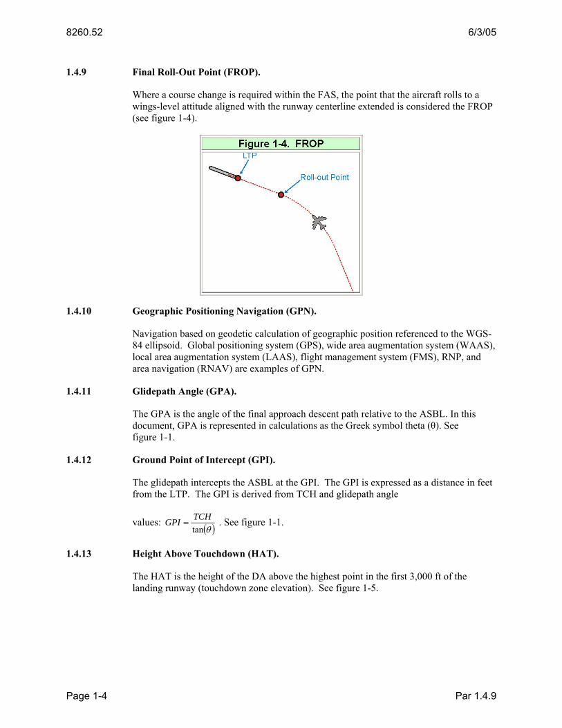
1.4.9 Final Roll-Out Point (FROP).
Where a course change is required within the FAS, the point that the aircraft rolls to a wings-level attitude aligned with the runway centerline extended is considered the FROP (see figure 1-4).
1.4.10 Geographic Positioning Navigation (GPN).
Navigation based on geodetic calculation of geographic position referenced to the WGS-84 ellipsoid. Global positioning system (GPS), wide area augmentation system (WAAS), local area augmentation system (LAAS), flight management system (FMS), RNP, and area navigation (RNAV) are examples of GPN.
1.4.11 Glidepath Angle (GPA).
The GPA is the angle of the final approach descent path relative to the ASBL. In this document, GPA is represented in calculations as the Greek symbol theta (θ). See figure 1-1.
1.4.12 Ground Point of Intercept (GPI).
The glidepath intercepts the ASBL at the GPI. The GPI is expressed as a distance in feet from the LTP. The GPI is derived from TCH and glidepath angle
values: ( )θtanTCHGPI = . See figure 1-1.
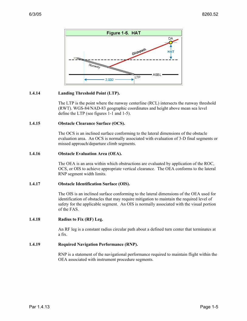
1.4.13 Height Above Touchdown (HAT).
The HAT is the height of the DA above the highest point in the first 3,000 ft of the landing runway (touchdown zone elevation). See figure 1-5.
Par 1.4.9 Page 1-4
6/3/05 8260.52
1.4.14 Landing Threshold Point (LTP).
The LTP is the point where the runway centerline (RCL) intersects the runway threshold (RWT). WGS-84/NAD-83 geographic coordinates and height above mean sea level define the LTP (see figures 1-1 and 1-5).
1.4.15 Obstacle Clearance Surface (OCS).
The OCS is an inclined surface conforming to the lateral dimensions of the obstacle evaluation area. An OCS is normally associated with evaluation of 3-D final segments or missed approach/departure climb segments.
1.4.16 Obstacle Evaluation Area (OEA).
The OEA is an area within which obstructions are evaluated by application of the ROC, OCS, or OIS to achieve appropriate vertical clearance. The OEA conforms to the lateral RNP segment width limits.
1.4.17 Obstacle Identification Surface (OIS).
The OIS is an inclined surface conforming to the lateral dimensions of the OEA used for identification of obstacles that may require mitigation to maintain the required level of safety for the applicable segment. An OIS is normally associated with the visual portion of the FAS.
1.4.18 Radius to Fix (RF) Leg.
An RF leg is a constant radius circular path about a defined turn center that terminates at a fix.
1.4.19 Required Navigation Performance (RNP).
RNP is a statement of the navigational performance required to maintain flight within the OEA associated with instrument procedure segments.
Par 1.4.13 Page 1-5

8260.52 6/3/05
1.4.20 Required Obstruction Clearance (ROC).
Sometimes referred to as required obstacle clearance, ROC is the minimum vertical clearance (in feet) that must exist between aircraft and the highest ground obstruction within the OEA of instrument procedure segments.
1.4.21 Runway Threshold (RWT).
The RWT marks the beginning of the portion of the runway usable for landing. It extends the full width of the runway (see figure 1-6).
1.4.22 Special Aircraft and Aircrew Authorization Required (SAAAR).
Aircraft may be equipped beyond the minimum standard for public RNP criteria and aircrews trained to achieve a higher level of instrument approach performance. SAAAR criteria are based on a higher level of equipage and additional aircrew requirements. Procedures that utilize SAAAR design criteria must be appropriately annotated.
1.4.23 Track to Fix (TF) Leg.
A TF leg is a geodesic path between two fixes.
1.4.24 Visual Glide Slope Indicator (VGSI).
The VGSI is an airport lighting aid that provides the pilot with a visual indication of the aircraft position relative to a specified glidepath to a touchdown point on the runway. Precision approach path indicators (PAPI) and visual approach slope indicators (VASI) are examples of VGSI systems.
1.4.25 Visual Segment.
The visual segment is the portion of the FAS OEA between the DA and the LTP.
1.4.26 Vertical Error Budget (VEB).
The VEB is a set of allowable values that contribute to the total error associated with a VNAV system. Application of equations using the VEB values determines the minimum vertical clearance that must exist between an aircraft on the nominal glidepath and ground obstructions within the OEA of instrument procedure segments. When the VEB is used in final segment construction, its application determines the OCS origin and slope ratio.
Par 1.4.20 Page 1-6

6/3/05 8260.52
1.5. DATA RESOLUTION.
Perform calculations using at least 0.01 unit of measure. Use calculation accuracy to at least 8 decimal places where calculation is accomplished by automated means. The following list specifies the minimum accuracy standard for documenting data expressed numerically. This standard applies to the documentation of final results only; e.g., a calculated adjusted glidepath angle of 3.04178° is documented as 3.05°. The standard does not apply to the use of variable values during calculation. Do not round intermediate results. Round the final result of calculations for documentation purposes. Use the most accurate data available for variable values.
1.5.1 Documentation Accuracy.
Document values to the following increments:
• WGS-84/NAD-83 latitudes and longitudes to the nearest one hundredth (0.01) arc second.
• LTP MSL elevation to the nearest foot,
• Glidepath angle to the next higher one hundredth (0.01) degree;
• Courses to the nearest one hundredth (0.01) degree;
• Distances to the nearest hundredth (0.01) unit; and
• Temperatures to the nearest hundredth (0.01) degree.
1.6 CALCULATION.
1.6.1 Mathematics Convention.
1.6.1 a. Definition of Mathematical Functions.
a+b indicates addition
a−b indicates subtraction
axb or ab indicates multiplication
ba or a⁄b or a÷b indicates division
(a−b) indicates the result of the process within the parenthesis
|a−b| indicates absolute value
≈ indicates approximate equality
a indicates the square root of quantity “a”
a2 indicates axa
tan(a) indicates the tangent of “a” degrees
tan-1(a) indicates the arc tangent of “a”
Par 1.5 Page 1-7

8260.52 6/3/05
sin(a) indicates the sine of “a” degrees
sin-1(a) indicates the arc sine of “a”
cos(a)a indicates the cosine of “a” degrees
cos-1(a) indicates the arc cosine of “a”
1.6.1 b. Operation Precedence (Order of Operations).
First: Grouping Symbols: parentheses, brackets, braces, fraction bars, etc. Second: Functions: Tangent, sine, cosine, arcsine and other defined functions Third: Exponentiations: powers and roots Fourth: Multiplication and Division: products and quotients Fifth: Addition and Subtraction: sums and differences
For example:
5−3×2 =−1 because multiplication takes precedence over subtraction
(5−3)×2 =4 because parentheses take precedence over multiplication
362
=12 because exponentiation takes precedence over division
169 + =5 because the square root sign is a grouping symbol
9 + 16 =7 because roots take precedence over addition
0.5)sin(30°
=1 because functions take precedence over division
sin( 5.030° )=0.8660254 because parentheses take precedence over functions
NOTE: Most calculators are programmed with these rules of precedence. When possible, let the calculator maintain all of the available digits of a number in memory rather than re-entering a rounded number. For highest accuracy from a calculator, any rounding that is necessary should be done at the latest opportunity.
1.6.2 Geodetic Calculation.
Geodetic calculations must be based on the WGS-84 ellipsoid model.
1.7 DESIGN CONCEPT.
Use these criteria to develop RNP SAAAR instrument approach procedures. The following basic conditions are considered in the development of obstacle clearance criteria for RNP approach procedures: The aircraft descends and decelerates from the en route environment or a terminal transition route through the initial/intermediate approach segments to the precision final approach fix (PFAF). The aircraft arrives at the DA and continues with visual reference to a landing on the runway or initiates a missed approach. The design of the instrument procedure defines the boundaries of the airspace within which the instrument operation will be conducted. This is the airspace that will “contain” (account for) all of the major factors influencing GPN: System accuracy, flight technical
Par 1.6.1a Page 1-8

6/3/05 8260.52
error, navigation system error, and error values that provide an acceptable level of continuity, availability, and integrity. For obstacle clearance purposes, the boundaries are specified as a nautical mile measurement perpendicular to the designed flight path. This measurement is specified as an RNP value or level. The primary OEA of RNP instrument procedures is defined as ± 2×RNP. Table 1-1 lists RNP values applicable to specific instrument procedure segments.
Table 1-1. RNP Values
RNP VALUES SEGMENT
MAXIMUM STANDARD MINIMUM
Feeder 2 2 1.0 Initial 1 1 0.1
Intermediate 1 1 0.1
Final 0.5 0.3 0.1 Missed Approach 1 1 0.1*
*See paragraph 4.2.1 for limitations of missed approach segment minimum values.
1.8 APPLICABILITY.
Approach procedures developed under these criteria are published under the authority of 14 CFR Part 97.33 and identified as “Special Aircraft and Aircrew Authorization Required.” General criteria contained in the latest editions of Order 8260.3, United States Standard for Terminal Instrument Procedures (TERPS), and RNAV and RNP specific criteria contained in Order 8260.19, Flight Procedures and Airspace, apply unless modified by these criteria.
1.9 PROCEDURE IDENTIFICATION.
Title RNP procedures “RNAV (RNP) RWY XX.” Where more than one RNAV approach with different ground-tracks are developed to the same runway, identify each with an alphabetical suffix beginning at the end of the alphabet. Title the procedure with the lowest minimums with the “Z” suffix, etc.
Examples
RNAV (RNP) Z RWY 13L (lowest HAT: example 250 ft) RNAV (RNP) Y RWY 13L (2
nd
lowest HAT: example 300 ft) RNAV (RNP) X RWY 13L (3
rd lowest HAT: example 350 ft)
1.10 PUBLISHED MINIMUMS.
RNP approach procedures are 3-dimensional approaches, lateral and vertical path deviation guidance is provided. Circling minimums are not developed. Evaluate the final segment for an RNP value of 0.3 and a standard RNP 1.0 missed approach, and publish the resulting minimums. If the resulting HAT value is ≥ 300 or no-lights visibility ≥ 1 SM, evaluate using a FAS RNP value <0.3 but ≥ 0.10 and/or a missed approach climb
Par 1.7 Page 1-9

8260.52 6/3/05
gradient or reduced MAS RNP, as appropriate, to determine lowest possible HAT/no-lights visibility. If at least a 50 ft reduction in HAT or ¼ SM reduction in visibility cannot be achieved, publish only the RNP 0.3 minimums, based on RNP 1 missed approach (standard missed approach). If the required reduction in minimums is possible, in addition to the RNP 0.3 minimums based on a standard missed approach, publish the lowest possible minimums. If the difference in minimums allows interim values that differ by at least 50 ft in HAT value or ¼ SM visibility, these values may also be published if desired (4 minima lines maximum). Note that RNP values lower than 0.3 may be selected to satisfy operational needs other than reduction of minimums; examples are: to achieve track to airspace separation, track to track separation, or to allow the DA to meet criteria of distance from the FROP.
1.10.1 Minimum Safe Altitudes (MAS).
Apply the MSA criteria contained in Order 8260.3, Volume 1, paragraph 221 for RNAV procedures.
1.11 CALCULATING TRUE AIRSPEED, TURN RADIUS, AND BANK ANGLE.
1.11.1 Calculating True Airspeed.
Determine the true airspeed (KTAS) for the turn using formula 1-1 and the airspeed for the highest category minimums published from table 1-2.
Formula 1-1 ( )[ ]00002.01 ×+×= altitudeVV KIASKTAS
Where V = Indicated Airspeed altitude = Maximum segment altitude in thousands of feet
Example Final Segment, CAT B, 1,500 feet
( )[ ]00002.01120 ×+×= altitudeVKTAS
Table 1-2. Indicated Airspeed (Knots) Indicated Airspeed by Aircraft Category Segment
Cat A Cat B Cat C Cat D Cat E**
Initial Intermediate 150 150 240 250 250
Final 90 120 140 165 As Specified
Missed Approach (MA) 110 150 240 265 As Specified
Minimum Airspeed
Restriction* Initial 110 140 210 210 As Specified
Intermediate 110 140 180 180 As Specified
Missed 100 130 165 185 As Specified
Par 1.10 Page 1-10

6/3/05 8260.52
*Minimum speed restriction value for use to reduce turn radius. Only one speed restriction per approach segment is allowed and the fastest airspeed appropriate for the highest speed category of aircraft serviced by the approach procedure must be used to determine the speed. AFS-400 or appropriate military authority approval is required when more than one speed restriction is desired for a particular approach segment (e.g. initial, intermediate, missed approach). AFS-400 or appropriate military authority approval is also required for missed approach airspeed restrictions when used for other than obstacle/terrain avoidance requirements. **Publish a chart note indicating the maximum CAT E airspeed.
1.11.2 Calculating Turn Radius For Fly-By Turns.
The turn radius applied at fly-by fixes is based on a standard bank angle of 18° at a true airspeed plus assumed tailwind. Locate the highest speed aircraft category that will be published on the approach procedure and use the appropriate knots indicated airspeed (VKIAS) in table 1-2, using the highest altitude allowed in the turn, calculate the VKTAS using formula 1-1. Obtain the highest expected altitude for feeder routes from the appropriate air traffic control facility. For initial and intermediate segments, use the minimum altitude for the fix prior to the turn fix. Use the tailwind component from table 1-3 for the highest altitude within the turn. (For turns initiated at an altitude located between values in the table, a new tailwind component may be interpolated for that turn. If an interpolated wind value is ever used below 500 ft, then the 0 ft value for wind begins with 15 kts.)
Par 1.11.1 Page 1-11

8260.52 6/3/05
*Other Tailwind Gradients may be used after a site-specific determination of wind based on that location’s meteorological history (using available information from other sources). Document source and value used on procedure form (FAA uses Form 8260-9).
Determine R using formula 1-2. Select the appropriate tailwind component in table 1-3 for the highest altitude within the turn and add the value to true airspeed.
Formula 1-2 Formula 1-2
R =( VKTAS + VKTW )2
× 0.0000449 where VKTAS
= True Airspeed V
KTW = Tail wind component Example
Intermediate Segment, altitude=1,500, Cat A-C Mins Published
R =(247.2 + 50 )2× 0.0000449 = 3.966
Par 1.11.2 Page 1-12
6/3/05 8260.52
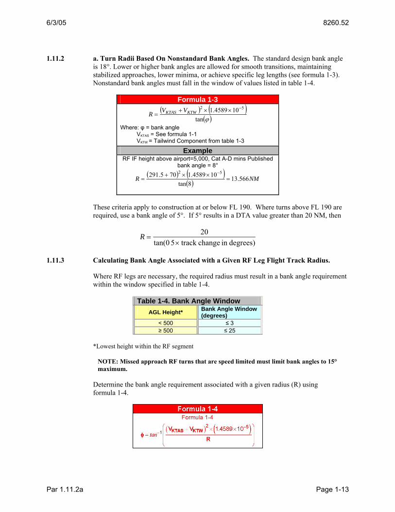
1.11.2 a. Turn Radii Based On Nonstandard Bank Angles. The standard design bank angle is 18°. Lower or higher bank angles are allowed for smooth transitions, maintaining stabilized approaches, lower minima, or achieve specific leg lengths (see formula 1-3). Nonstandard bank angles must fall in the window of values listed in table 1-4.
Formula 1-3 ( ) ( )
( )ϕtan104589.1 52 −××+
= KTWKTAS VVR
Where: φ = bank angle VKTAS = See formula 1-1 VKTW = Tailwind Component from table 1-3
Example RF IF height above airport=5,000, Cat A-D mins Published
bank angle = 8° ( ) ( )
( ) NMR 566.138tan
104589.1705.291 52=
××+=
−
These criteria apply to construction at or below FL 190. Where turns above FL 190 are required, use a bank angle of 5°. If 5° results in a DTA value greater than 20 NM, then
degrees)in changetrack 5 tan(020
×=R
1.11.3 Calculating Bank Angle Associated with a Given RF Leg Flight Track Radius.
Where RF legs are necessary, the required radius must result in a bank angle requirement within the window specified in table 1-4.
Table 1-4. Bank Angle Window AGL Height* Bank Angle Window
(degrees) < 500 ≤ 3 ≥ 500 ≤ 25
*Lowest height within the RF segment
NOTE: Missed approach RF turns that are speed limited must limit bank angles to 15° maximum.
Determine the bank angle requirement associated with a given radius (R) using formula 1-4.
Par 1.11.2a Page 1-13

8260.52 6/3/05
1.12 CALCULATION OF RADIO ALTIMETER (RA) HEIGHT.
Some aircraft bank angles are limited below 400 ft radio altitude (AGL). If any portion of the turn is expected to occur below 400 ft AGL, the Flight Control Computer (FCC – not the FMC) bank angle limitation must be considered for the LNAV mode. In these cases, use the limited bank angle in the turn calculation. Document the limited bank angle on the procedure forms (FAA uses Form 8260-9). AFS-400 (or equivalent DOD agency as appropriate) approval is required for greater bank angles in these cases. To determine RA height at any point on final, determine the distance (d) measured along the final approach course (FAC) from GPI. Obtain the terrain elevation at point (d) feet from GPI on the final course track. Subtract the terrain elevation from the on-glidepath altitude to calculate the RA (see figure 1-7). See formulas 1-5 and 1-6.
Formula 1-5
( )θtanElevation Threshold - AltitudeAircraft
=d
Example
( ) '77028.43tan26-276
==d
Formula 1-6
RA = Aircraft Altitude - Terrain Elev Example
RA = 276 − 38 = 238
Par 1.11.3 Page 1-14

6/3/05 8260.52
1.13 DTA APPLICATION.
DTA is a calculated value for use in determining minimum straight segment length where a turn is required at the beginning or ending fix (see figure 1-8). See paragraph 2.3 for determination of minimum segment length. Use formula 1-7 to determine DTA for any given turn.
Figure 1-8. DTA Formula 1-7
⎟⎠⎞
⎜⎝⎛=
2tan αRDTA
α = degrees of turn R = Turn radius
1.14 CALCULATION OF VISIBILITY MINIMUMS.
Calculate visibility with and without lights. Where approach lights are used to reduce visibility, publish a note containing the no-light visibility. Example note: “Inoperative table does not apply. Visibility without lights is 1 ½ mile.” Calculate the slant distance from DA to the first light of the approach lighting system of runways served by approach lights or to the landing threshold of runways without approach lights using formula 1-8 rounded to the next higher reportable value (see figures 1-9 and 1-10).
Formula 1-8
( ) 221 HdVisibility +−=
where d = distance (ft) along ASBL from LTP to DA l = length of lighting system H = DA height above threshold
Example Example -w lights
( ) 07.1875273240009.4255 =+− { 83 SM}
Example –w/o lights
84.426327309.4255 22 =+ { 87 SM}
Par 1.13 Page 1-15

8260.52 6/3/05
1.15 EVALUATION OF ACTUAL AND ASSUMED OBSTACLES (AAO).
1.15.1 Accuracy Uncertainty Standards.
Apply the vertical and horizontal accuracy standards in Order 8260.19, paragraphs 272, 273, 274, and appendix 2. If specific terrain information (a site inspection, local information, or site survey, etc.) is not available, apply the following:
• The next higher contour line minus one unit of elevation; or if other terrain data formats are used (e.g. DEMs) instead of terrain contour lines, use the DEM data point value, and
• An assumed canopy height consistent with local area vegetation (since canopy height varies throughout the country, verify the height value to use with the FAA regional FPO); or
• An AAO of 199 feet above the next higher gradient line minus one unit of elevation, unless it penetrates the Part 77 surfaces for which a Part 77 survey has been performed.
Par 1.14 Page 1-16

6/3/05 8260.52
1.15.2 Application of Vertical and Horizontal Accuracy Uncertainty.
Apply the obstruction vertical and horizontal accuracy code values to all obstructions. From a 3-dimensional perspective, a point described by latitude, longitude, and elevation can be evaluated as a cylinder when applying both vertical and horizontal accuracy (see figure 1-11).
1.16 INFORMATION UPDATE.
For your convenience, FAA Form 1320-19, Directive Feedback Information, is included at the end of this order to note any deficiencies found, clarifications needed, or suggested improvements regarding the contents of this order. When forwarding your comments to the originating office for consideration, please use the "Other Comments" block to provide a complete explanation of why the suggested change is necessary.
Par 1.15.2 Page 1-17 (and 1-18)


6/3/05 8260.52
CHAPTER 2. FEEDER, INITIAL, AND INTERMEDIATE SEGMENTS
2.0 GENERAL.
Feeder, initial, and intermediate segments provide a smooth transition from the en route environment to the final approach segment. Descent to glidepath intercept and configuring the aircraft for final approach must be accomplished in these segments. Design RNP segments using the most appropriate leg type (TF or RF) to satisfy obstruction and operational requirements in feeder, initial, intermediate, final, and missed approach segments. Generally, TF legs are considered first but RF legs may be used in lieu of TF-TF turns for turn path control, procedure simplification, or improved flyability.
2.1 CONFIGURATION.
RNP navigation enables the geometry of approach procedure design to be very flexible. The “Y” configuration is preferred where obstructions and air traffic flow allow. The approach design should provide the least complex configuration possible to achieve the desired minimums. See figure 2-1 for examples. Fly-by turns at the PFAF are limited to a maximum of 15°.
2.2 RNP SEGMENT WIDTH.
RNP values are specified in increments of a hundredth (0.01) of a NM. Segment width is defined as 4×RNP; segment half-width (semi-width) is defined as 2×RNP (see figure 2-2). Standard RNP values for instrument procedures are listed in table 1-1.
Par 2.0 Page 2-1

8260.52 6/3/05
Apply the standard RNP values listed in table 2-1 unless a lower value is required to achieve the required ground track or lowest minimums. The lowest RNP values are listed in the “MINIMUM” column of table 2-1.
2.3 RNP SEGMENT LENGTH.
Design segments with sufficient length to accommodate the required descent as close to the OPTIMUM gradient as possible and DTA (see paragraph 1.13) where turns are required. Minimum straight segment (any segment) length is 2×RNP (+DTA as appropriate for fly-by turn constructions). Paragraph 2.8 applies where RNP changes occur (RNP value changes 1 RNP prior to fix). The maximum initial segment length (total of all sub segments) is 50 NM.
2.4 RNP SEGMENT DESCENT GRADIENT.
Design instrument approach procedure segments to provide descent at the standard gradient. Where necessary to achieve obstacle clearance, descent gradient may be increased. Table 2-1 lists the standard and maximum allowable descent gradients.
Par 2.2 Page 2-2

6/3/05 8260.52
Table 2-1. Descent Gradient Constraints DESCENT GRADIENT (FT/NM) SEGMENT
STANDARD MAXIMUM Feeder 250 500
Initial 250 **800 500 **1000
Intermediate ≤ 150 Equal to Final Segment Gradient*
Final 318 See Table 3-1
* If a higher than standard gradient is required, a prior segment must provide a gradient to allow the aircraft to configure for final segment descent. ** DoD Only
2.4.1 Descent Gradient Calculation.
2.4.1 a. TF Segments.
See figure 2-3, and calculate the descent gradient using formula 2-1.
Formula 2-1
dbaDG −
=
where a=minimum altitude at beginning fix
b=minimum altitude at ending fix
d=distance (NM) between fixes
Example
Example: a=4,500 b=3,600 d=5.77
98.155577
600,3500,4=
−=DG
Par 2.4 Page 2-3

8260.52 6/3/05
2.4.2 RF Segment.
See figure 2-4, and calculate the descent gradient using formula 2-1 where d is calculated using formula 2-2.
Formula 2-2
180πα ××
=Rd
where α = degrees of arc
R = turn radius
Example
α =55° R=6.0
76.5180
0.655=
××=
πd
2.5 RNP SEGMENT ROC.
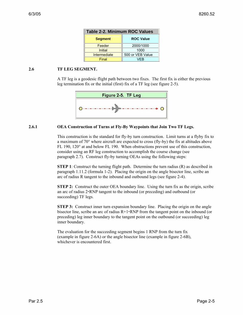
Minimum ROC requirements are listed by segment type in table 2-2.
Par 2.4.2 Page 2-4
6/3/05 8260.52
Table 2-2. Minimum ROC Values Segment ROC Value
Feeder 2000/1000 Initial 1000
Intermediate 500 or VEB Value Final VEB
2.6 TF LEG SEGMENT.
A TF leg is a geodesic flight path between two fixes. The first fix is either the previous leg termination fix or the initial (first) fix of a TF leg (see figure 2-5).
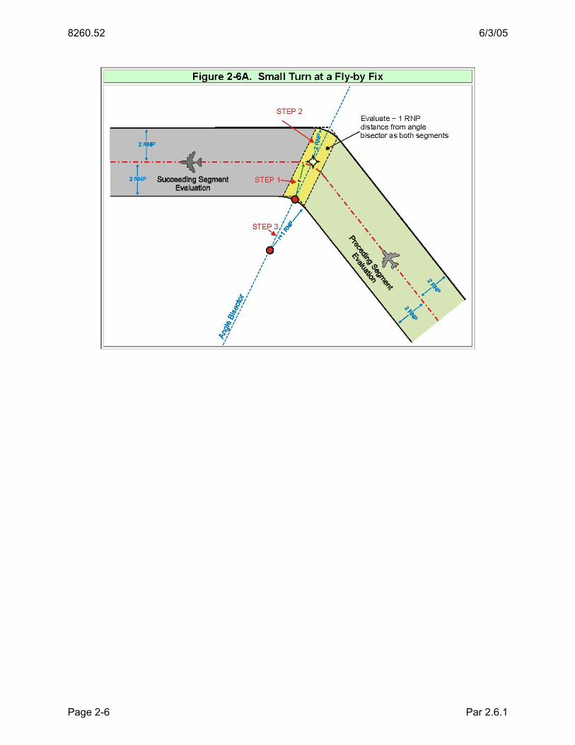
2.6.1 OEA Construction of Turns at Fly-By Waypoints that Join Two TF Legs.
This construction is the standard for fly-by turn construction. Limit turns at a flyby fix to a maximum of 70° where aircraft are expected to cross (fly-by) the fix at altitudes above FL 190, 120° at and below FL 190. When obstructions prevent use of this construction, consider using an RF leg construction to accomplish the course change (see paragraph 2.7). Construct fly-by turning OEAs using the following steps:
STEP 1: Construct the turning flight path. Determine the turn radius (R) as described in paragraph 1.11.2 (formula 1-2). Placing the origin on the angle bisector line, scribe an arc of radius R tangent to the inbound and outbound legs (see figure 2-4).
STEP 2: Construct the outer OEA boundary line. Using the turn fix as the origin, scribe an arc of radius 2 RNP tangent to the inbound (or preceding) and outbound (or succeeding) TF legs.
STEP 3: Construct inner turn expansion boundary line. Placing the origin on the angle bisector line, scribe an arc of radius R+1 RNP from the tangent point on the inbound (or preceding) leg inner boundary to the tangent point on the outbound (or succeeding) leg inner boundary.
The evaluation for the succeeding segment begins 1 RNP from the turn fix (example in figure 2-6A) or the angle bisector line (example in figure 2-6B), whichever is encountered first.
Par 2.5 Page 2-5
8260.52 6/3/05
Par 2.6.1 Page 2-6

6/3/05 8260.52
2.7 RF LEG SEGMENT.
An RF leg may be designed to accommodate a course change where obstructions prevent the design of a fly-by turn at a fix, or to accommodate other operational requirements. RF legs are used to control the ground track of a turn. The curved leg begins tangent to the previous segment course at its terminating fix and ends tangent to the follow-on course at its beginning fix (see figure 2-7). OEA construction limits turn radius to ≥2×RNP. The obstruction evaluation area boundaries are parallel arcs.
STEP 1. Determine the turn radius (R) necessary to avoid obstructions. Apply paragraph 1.11.3 to verify the bank angle associated with R is within the table 1-4 specified values.
STEP 2. Locate the turn center at a perpendicular distance “R” from the preceding and following segments.
STEP 3. Construct flight path. Scribe an arc of radius “R” from the tangent point on the preceding course to the tangent point on the following course.
Par 2.6.1 Page 2-7

8260.52 6/3/05
STEP 4. Construct outer OEA boundary. Scribe an arc of radius R+2 RNP from the tangent point on the preceding segment outer boundary to the tangent point on the following course outer boundary.
STEP 5. Construct inner OEA boundary. Scribe an arc of radius R-2 RNP from the tangent point on the preceding segment inner boundary to the tangent point on the following course inner boundary.
2.8 CHANGING SEGMENT WIDTH (RNP VALUES).
Changes in RNP values must occur at a fix. The aircraft avionics transition to the new RNP value no later than reaching the fix marking the value change. Therefore, the area within ± 1 RNP of the fix must be evaluated for both segments. RNP reduction is illustrated in figure 2-8A, RNP increase is illustrated in figure 2-8B, and RNP changes involving RF legs are illustrated in figure 2-8C.
NOTE: RNP reductions are not allowed on final after passing the PFAF or in segments where the VEB is applied.
Par 2.7 Page 2-8

6/3/05 8260.52
Par 2.8 Page 2-9

8260.52 6/3/05
Par 2.10 Page 2-10

6/3/05 8260.52
2.9 EFFECTS OF COLD TEMPERATURE IN THE INTERMEDIATE SEGMENT.
When establishing the intermediate segment minimum altitude (glidepath intercept altitude), compare the difference between the 500-ft intermediate ROC value and the ROC value provided by the VEB OCS if extended to the controlling obstacle along track distance from LTP. If the VEB ROC value exceeds 500, apply this ROC value in lieu of 500 ft in the intermediate segment (see figure 2-9). Applying VEB ROC will raise the intermediate segment altitude. Where this application yields PFAF to LTP distances greater than 7.5 NM, Flight Technologies and Procedures Division, AFS-400, approval is required.
Par 2.8 Page 2-11

8260.52 6/3/05
Par 2.9 Page 2-12

6/3/05 8260.52
CHAPTER 3. FINAL APPROACH SEGMENT (FAS)
3.0 GENERAL.
RNP approaches are 3-D procedures; the final segment provides the pilot with final segment vertical and lateral path deviation information based on Baro VNAV systems. Therefore, RNP procedures may not be developed for locations with full time remote altimeter or where the final segment overlies precipitous terrain. The glidepath qualification surface (GQS) described in Order 8260.3, Volume 3, paragraph 2.12 must be clear in order to publish a 3-D procedure to the runway (for procedures with an RF turn in the final segment, the GQS terminates at the DA or FROP, whichever is closer to LTP). The final approach segment OCS is based on limiting the vertical error performance of Baro VNAV avionic systems to stated limits. Minimum and maximum temperature limitations are specified on the approach chart for aircraft that do not have temperature-compensating systems. The minimum height above touchdown (HAT) value is 250 ft.
3.1 FINAL SEGMENT RNP VALUES.
Evaluate the final segment for an RNP value of 0.3. If the resulting HAT value is ≥ 300 or no-lights visibility ≥ 1 SM, evaluate using an RNP value <0.3 but ≥ 0.10 to determine the largest RNP value that will yield the lowest possible HAT/no-lights visibility. If at least a 50 ft reduction in HAT or ¼ SM reduction in visibility cannot be achieved, publish only the RNP 0.3 minimums. See related paragraph 1.10.
3.2 GLIDEPATH ANGLE AND TCH REQUIREMENTS.
The OPTIMUM (design standard) glidepath angle is 3°. Lower angles require Flight Standards approval. Glidepath angles higher than 3° are authorized only where obstacles prevent use of 3° or minimum temperature limitations restrict approach availability when the approach is operationally needed. Table 3-1 lists the highest allowable glidepath angle by aircraft category. If the required glidepath angle is greater than the maximum for an aircraft category, do not publish minimums for the category. Table 3-2 lists standard threshold crossing height (TCH) values and recommended ranges of values appropriate for cockpit-to-wheel height groups 1 through 4. Three-dimensional (3-D) procedures serving the same runway should share common TCH and glidepath angle values. If an instrument landing system (ILS) serves the runway, use the ILS TCH and glidepath angle values. If there is no ILS but a visual glide slope indicator (VGSI) system with a suitable TCH and glidepath angle serves the runway, use the VGSI TCH and glidepath angle. Otherwise, select an appropriate TCH value from table 3-2, and 3° glidepath angle.
Par 3.0 Page 3-1

8260.52 6/3/05
Table 3-1. Maximum Glidepath Angle (θ) Gradient Category θ %
A (80 knots or less) 6.4 FT/NM 682 11.22
A (81-90 knots) 5.7 606 9.98 B 4.2 446 7.34 C 3.6 382 6.29
D&E 3.1 329 5.42
Table 3-2. TCH Requirements Representative Aircraft Type Remarks
Approximate Glidepath-to-Wheel Height
Recommended TCH ± 5 Feet
HEIGHT GROUP 1 General aviation, Small commuters, Corporate turbojets, T-37, T-38, C-12, C-20, C-21, T-1, Fighter Jets
10 Feet or less 40 Feet
Many runways less than 6,000 ft long with reduced widths and/or restricted weight bearing which would normally prohibit landings by larger aircraft.
HEIGHT GROUP 2 F-28, CV-340/440/580, B-737, C-9, DC-9, C-130, T-43, B-2, S-3
15 Feet 45 Feet Regional airport with limited air carrier service.
HEIGHT GROUP 3 B-727/707/720/757, B-52, C-135, C-141, C-17, E-3, P-3, E-8 20 Feet 50 Feet
Primary runways not normally used by aircraft with ILS glidepath-to-wheel heights exceeding 20 ft.
HEIGHT GROUP 4 B-747/767/777, L-1011, DC-10, A-300, B-1, KC-10, E-4, C-5, VC-25
25 Feet 55 Feet Most primary runways at major airports.
NOTE 1: To determine the minimum allowable TCH, add 20 ft to the glidepath-to-wheel height.
NOTE 2: To determine the maximum allowable TCH, add 50 ft to the glidepath-to-wheel height.
NOTE 3: Publish a note indicating the VGSI not coincident with the procedure GPA when the VGSI angle is more than 0.2° from the GPA, or when the VGSI TCH is more than 3 ft from the procedure TCH.
The glidepath angle should not result in a descent rate (DR) greater than 1,000 ft-per-minute for aircraft served by the procedure. Use formula 3-1 to calculate the DR for any given 3-D procedure.
Par 3.2 Page 3-2

6/3/05 8260.52
Formula 3-1 DR= VKIAS×(1+0.00002p)×sin(θ)×101.26859
Where: V KIAS=Indicated Airspeed p=PFAF Altitude θ=Glidepath Angle
Example VKIAS=165 p=2,100 θ=3°
DR=165×(1+0.00002×2,100)×sin(3)×101.26859=911.227ft/min
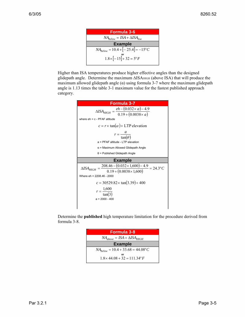
3.2.1 Controlling the Effects of Temperature on the Glidepath Angle.
RNP final segment vertical guidance is provided by barometric VNAV. The effective glidepath angle (actual angle flown) depends on the temperature deviation from standard (ISA) associated with airport elevation. ISA for the airport may be calculated using formula 3-2.
NOTES:
1. The formula for conversion from Celsius to Fahrenheit is also given; however, the use of ISA values in calculation of minimum and maximum angles below will always use Celsius values.
2. Examples 3-2 through 3-8 in this section use PFAF altitude 2000, Airport and LTP elevation 400, Glidepath angle (θ) 3°.
Formula 3-2
500elevationairport 15 −°=°CISA
( ) 328.1 +°×=° CISAFISA
Example
CCISA °=−°=° 14250040015
( ) FFISA °=+×=° 56.573240.108.1
The approach procedure should offer obstacle protection within a temperature range that can reasonably be expected to exist at the airport. Establish the lower temperature limit from the 5-year average lowest temperature for the coldest month of the year (ACT). Determine the difference (∆ISALOW) between this temperature and ISA temperature for the airport using formula 3-3.
Formula 3-3 ∆ISALOW=−(ISA−ACT)
where ACT = Average Cold Temperature
Example ∆ISALOW=−(14.2−[−15.0])=−29.2C°
where ISA = 14.2°C ACT = -15.0°C
Par 3.2 Page 3-3

8260.52 6/3/05
The effective glidepath angle at ∆ISALOW (θ∆ISAlow) must not be less than 0.917θ (0.917 times the published glidepath angle). For example, 0.917× 3.0° = 2.75°. Calculate the θ∆ISAlow using formula 3-4.
Formula 3-4
⎟⎠⎞
⎜⎝⎛ +
= −∆ r
eaISAlow
1tanθ
where a = PFAF altitude - LTP Elevation
[ ]( ) 9.4032.00038.019.0 +×+×+×∆= aaISAe low
( )θtanar =
Θ = Published Glidepath Angle
Example [ ] 76.2
82.3052998.126600,1tan 1 =⎟
⎠⎞
⎜⎝⎛ −+
= −∆ISAlowθ
where a = 2,000 - 400 [ ]( ) 9.4600,1032.0600,10038.019.02.29 +×+×+×−=e
( )3tan600,1
=r
If the effective glidepath angle is less than 0.917θ, calculate the ∆ISAlow to achieve an angle of 0.917θ using formula 3-5.
Formula 3-5 ( )( )a
aelISAlow ×+−×−−
=∆0038.019.0
9.4032.0
where el = PFAF altitude - b ( ) elevation LTP917.0tan +×= θrb
( )θtanar =
a = PFAF altitude - LTP elevation Example ( )( ) 25.30
600,10038.019.09.4600,1032.056.133
−=×+
−×−−=∆ lowISA
where el = 2000 – b ( ) 40075.2tan82.529,30 +×=b
( )3tan600,1
=r
a = 2,000 - 400
Determine the published low temperature limitation for the procedure derived from formula 3-6, using the ∆ISALOW derived from formula 3-3 or 3-5 as appropriate. If the temperature history for the location indicates the low temperature limitation is frequently encountered during established busy recovery times, consider raising the glidepath angle to the lowest angle (within table 3-1 limits) that will make the approach usable more often.
Par 3.2.1 Page 3-4
6/3/05 8260.52
Formula 3-6 lowbelow ISAISANA ∆+=
Example [ ] CNAbelow °−=−+= 154.254.10
or
[ ] F°=+−× 532158.1
Higher than ISA temperatures produce higher effective angles than the designed glidepath angle. Determine the maximum ∆ISAHIGH (above ISA) that will produce the maximum allowed glidepath angle (α) using formula 3-7 where the maximum glidepath angle is 1.13 times the table 3-1 maximum value for the fastest published approach category.
Formula 3-7 ( )
( )aaehISAHIGH ×+−×−
=∆0038.019.0
9.4032.0
where eh = c - PFAF altitude
( ) elevation LTPtan +×= αrc
( )θtanar =
a = PFAF altitude - LTP elevation
α = Maximum Allowed Glidepath Angle
θ = Published Glidepath Angle
Example ( )( ) CISAHIGH °=
×+−×−
=∆ 3.24600,10038.019.0
9.4600,1032.046.208
Where eh = 2208.46 - 2000
( ) 40039.3tan82.30529 +×=c
( )3tan600,1
=r
a = 2000 - 400
Determine the published high temperature limitation for the procedure derived from formula 3-8.
Formula 3-8 HIGHabove ISAISANA ∆+=
Example CNAbelow °=+= 08.4468.334.10
or F°=+× 34.1113208.448.1
Par 3.2.1 Page 3-5

8260.52 6/3/05
3.3 TURNS IN THE FAS.
Fly-by turns are not allowed in the FAS. Where turns are necessary, use an RF leg. Design procedures that incorporate an RF turn in the final segment to establish the aircraft on a straight segment aligned with the runway centerline prior to reaching DA. The Final Rollout Point (FROP) is the initial fix of the straight segment (see figure 3-1). Locate the FROP at the greatest distance resulting from application of formulas 3-9 and 3-10A/B as appropriate.
Apply formula 3-9 to assure rollout occurs at least 500 ft above LTP elevation.
Formula 3-9 (500’ above LTP)
( )θtan500
500TCHD −
= where θ = glidepath angle
Example
( ) '35.85483tan52500
500 =−
=D where θ = 3°
TCH = 52 feet
Apply formula 3-10A where the initial MAS RNP value is standard (RNP 1.0) or the MAS is based on conventional NAVAIDs.
Formula 3-10A (5 sec stabilization)
( ) ( ) 44.815tansec5 ×++−
= TASVTCHHATDθ
where θ = glidepath angle
VTAS = final segment true airspeed
Example Cat D 165 Kts, Altitude 2000, θ=3°, TCH=52, HAT=300
VTAS = 165 ×[1+(2000×0.00002)]=171.60
( ) ( ) 03.630744.81560.1713tan52300
sec5 =×++−
=D
Par 3.3 Page 3-6

6/3/05 8260.52
Apply formula 3-10B where the initial MAS RNP value is restricted to less than 1.0.
Formula 3-10B (15 sec stabilization)
( ) ( ) 32.2515tansec15 ×++−
= TASVTCHHATDθ
where θ = glidepath angle VTAS = final segment true airspeed
Example
Cat D 165 Kts, Altitude 2000, θ=3°, TCH=52, HAT=300 VTAS=165×[1+(2000+0.00002)]=171.60
( ) ( ) 83.945632.251560.1713tan52300
sec15 =×++−
=D
3.4 DETERMINING PFAF LOCATION. (In all cases, the PFAF will be identified as a named fix.)
The OPTIMUM alignment is a TF segment straight in from PFAF to LTP on runway centerline extended. If necessary, the TF course may be offset by up to 3°. Where the course is offset, it must cross runway centerline extended at least 1500 out from LTP. A final segment may be designed using an RF leg segment when obstacles or operational requirements prevent a straight-in approach from PFAF to LTP. Determine the along-track distance from the LTP (FTP if offset) to the point the glidepath intercepts the
Par 3.3 Page 3-7

8260.52 6/3/05
intermediate segment minimum altitude (DPFAF). Calculate DPFAF using formula 3-11. Determine which leg (TF or RF) the PFAF is located on by comparing DPFAF to the leg lengths
Formula 3-11 ( )
( ) ⎥⎦
⎤⎢⎣
⎡⎟⎟⎠
⎞⎜⎜⎝
⎛+−−
+−−= −
537,890,20537,890,2090sinsin90609,364 1
tchbaDPFAF
θθ
Where: a = minimum intermediate altitude
b = LTP elevation in feet
θ = glidepath angle
tch = threshold crossing height
Example a = 2000 b = 400 tch = 52 θ = 3°
( )( ) 454.29147
537,890,20524002000537,890,20390sinsin390609,364 1 =⎥
⎦
⎤⎢⎣
⎡⎟⎟⎠
⎞⎜⎜⎝
⎛+−−
+−−= −
PFAFD
3.4.1 PFAF LOCATED ON TF LEG.
Geodetically calculate the latitude and longitude of the PFAF using the reverse true course of the TF leg (true course – 180°) and DPFAF measured along-track from the LTP (FTP if offset). Where the FAS consists of a single TF leg, a Microsoft Excel spreadsheet (see figure 3-2) is provided on the AFS-420 website to calculate DPFAF and the WGS-84 latitude and longitude of the PFAF. Go to the following Internet link:
http://av-info.faa.gov/terps/ -Then select link: RNP SAAAR VEB.
Par 3.4 Page 3-8

6/3/05 8260.52
3.4.2 PFAF Located on RF Leg.
The PFAF must be located at the initial fix of a TF or RF segment. Where the PFAF must be located within an RF segment, the segment must be broken into two segments, each having the same radius and turn center, with the PFAF coincident with the initial fix of the second segment. The length in feet of the RF leg from the FROP to PFAF can be calculated by formula 3-12.
Formula 3-12 LengthRF = DPFAF − DFROP
Example LengthRF = 29147.45−8548.35 = 20599.10
where DPFAF = 29147.45 (from formula 3-9)
DFROP = 8548.35 (from formula 3-10)
Par 3.4.1 Page 3-9
8260.52 6/3/05
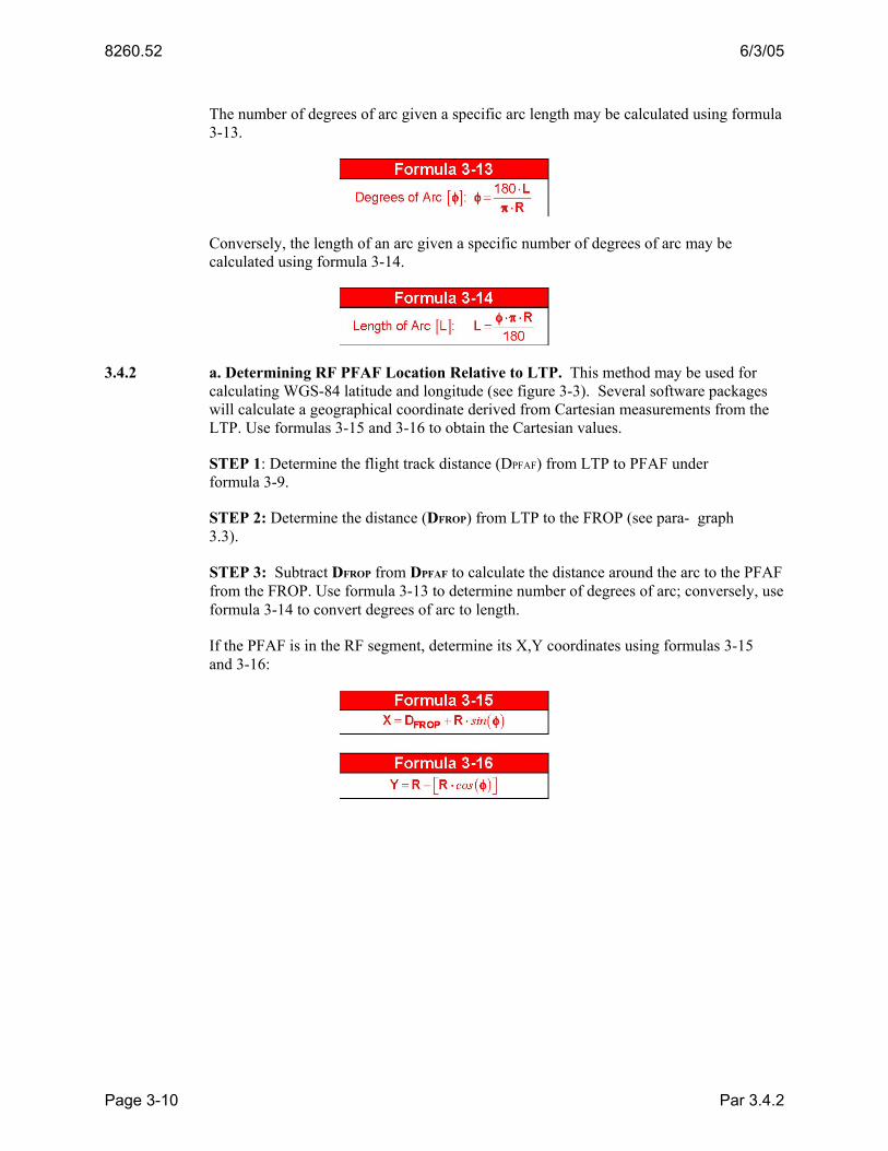
The number of degrees of arc given a specific arc length may be calculated using formula 3-13.
Conversely, the length of an arc given a specific number of degrees of arc may be calculated using formula 3-14.
3.4.2 a. Determining RF PFAF Location Relative to LTP. This method may be used for calculating WGS-84 latitude and longitude (see figure 3-3). Several software packages will calculate a geographical coordinate derived from Cartesian measurements from the LTP. Use formulas 3-15 and 3-16 to obtain the Cartesian values.
STEP 1: Determine the flight track distance (DPFAF) from LTP to PFAF under formula 3-9.
STEP 2: Determine the distance (DFROP) from LTP to the FROP (see para- graph 3.3).
STEP 3: Subtract DFROP from DPFAF to calculate the distance around the arc to the PFAF from the FROP. Use formula 3-13 to determine number of degrees of arc; conversely, use formula 3-14 to convert degrees of arc to length.
If the PFAF is in the RF segment, determine its X,Y coordinates using formulas 3-15 and 3-16:
Par 3.4.2 Page 3-10

6/3/05 8260.52
3.5 FINAL SEGMENT OEA.
The final segment OEA begins 1×RNP prior to the PFAF and extends to the LTP/FTP. The OEA contains a sloping OCS to evaluate obstructions prior to DA, and a visual segment surface from DA to LTP (see figure 3-4).
Par 3.4.2a Page 3-11

8260.52 6/3/05
The OCS origin distance from LTP (DVEB) and its slope are determined through application of the Vertical Error Budget (VEB). The VEB calculations require input of values for two variables: final segment RNP value and temperature (°C) deviation (∆ISALOW) below the airport ISA temperature. A link to a Microsoft Excel spread sheet that performs the VEB calculations is available on the internet at the following address: http://av-info.faa.gov/terps/ under the label “RNP SAAAR VEB”. See figure 3-2.
Calculate the MSL elevation of the OCS at any distance ‘d’ from RWT using formula 3-17.
Formula 3-17
slope
VEBelevMSL OCS
DdLTPVEB −+= VEB slope
where d = distance along course centerline from RWT
DVEB = distance of OCS origin from LTP
OCSslope = OCS slope from VEB calculations
Example
45.42671.20
42.355923.4107400 =−
+=MSLVEB
where d = 4107.23
DVEB = 3559.42
OCSslope = 20.71
LTPelev = 400
Par 3.5 Page 3-12

6/3/05 8260.52
3.5.1 Obstacle Evaluation.
If the FAS OCS is not penetrated, the MINIMUM HAT value of 250 ft applies. Limitation: The distance from LTP to DA must not be less than the distance from LTP to OCS origin (DVEB). Determine the DA using formula 3-18.
Obstacles that penetrate an OCS may be mitigated by one of the following actions: remove or lower obstacle, lower the RNP value for the segment (if appropriate), adjust the lateral path, raise glidepath angle, raise TCH (within table 3-2 limits), or adjust HAT (see figure 3-5 and formula 3-19).
NOTE: DVEB decreases slightly when glidepath angle is increased. Therefore if the angle is increased to accommodate a penetration, the VEB must be recalculated and the OCS re-evaluated.
Formula 3-19 ( ) ( ) ( )TDZELTPTCHOCSpdHAT elevVEBadjusted −++⋅+⋅= θtan
where θ = glidepath angle
d = distance (ft) LTP to obstacle
p = amount of penetration (ft)
OCSVEB = Slope of VEB OCS
Example ( ) ( ) ( ) 82.281405400522017843153tan =−++⋅+⋅=adjustedHAT
where θ = 3° d = 4315 p = 8'
OCS VEB = 20.71 LTPelev = 400
TDZE = 405
Par 3.5.1 Page 3-13
8260.52 6/3/05
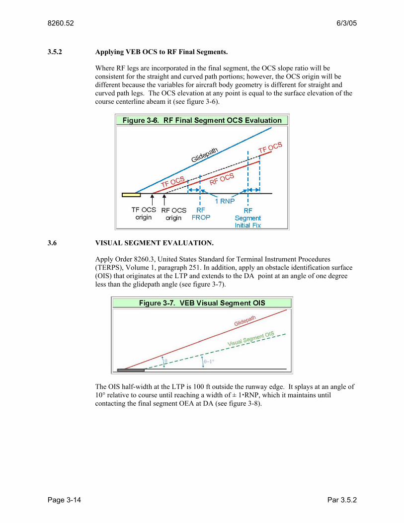
3.5.2 Applying VEB OCS to RF Final Segments.
Where RF legs are incorporated in the final segment, the OCS slope ratio will be consistent for the straight and curved path portions; however, the OCS origin will be different because the variables for aircraft body geometry is different for straight and curved path legs. The OCS elevation at any point is equal to the surface elevation of the course centerline abeam it (see figure 3-6).
3.6 VISUAL SEGMENT EVALUATION.
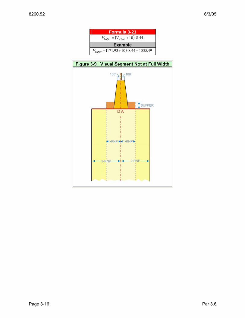
Apply Order 8260.3, United States Standard for Terminal Instrument Procedures (TERPS), Volume 1, paragraph 251. In addition, apply an obstacle identification surface (OIS) that originates at the LTP and extends to the DA point at an angle of one degree less than the glidepath angle (see figure 3-7).
The OIS half-width at the LTP is 100 ft outside the runway edge. It splays at an angle of 10° relative to course until reaching a width of ± 1 RNP, which it maintains until contacting the final segment OEA at DA (see figure 3-8).
Par 3.5.2 Page 3-14

6/3/05 8260.52
Formula 3-20
( )
( )10tan2
Rwy Width10011548.60761 ⎟⎠⎞
⎜⎝⎛ +−⋅⋅
=RNP
Splaylength
Example
( )
( ) 43.417610tan
215010011548.607615.01
=⎟⎠⎞
⎜⎝⎛ +−⋅⋅
=lengthSplay
where RNP = 0.15
Rwy Width = 150
Calculate the segment length (Splaylength) required to reach ±1 RNP using formula 3-20. If Splaylength is greater than the distance from LTP to DA, construct a ±1 RNP buffer area aligned with the runway centerline extended from the DA point toward the LTP for a distance of “Dbuffer” as shown in formula 3-21 and figure 3-9 based on largest category minima published and the PFAF altitude. The buffer OIS is a continuation of the VEB OCS from DA to the OCS origin, or Dbuffer, whichever is less. An obstacle may penetrate the visual/buffer OIS (figures 3-8 and 3-9) provided it is charted and appropriate mitigations are identified and approved by AFS-400.
Par 3.6 Page 3-15
8260.52 6/3/05
Formula 3-21 ( ) 44.810 ⋅+= KTASbuffer VV
Example ( ) 49.153544.81093.171 =⋅+=bufferV
Par 3.6 Page 3-16

6/3/05 8260.52
CHAPTER 4. MISSED APPROACH SEGMENT (MAS)
4.0 GENERAL.
These criteria are based on the following assumptions:
• Aircraft climb at a rate of at least 200 ft/NM (3.29%) in the missed approach segment.
• A non-guided missed approach is not RNP and is treated as dead-reckoning navigation (subject to 15° OEA splay).
• The OEA expansion where FAS RNP levels less than RNP-1 are continued into the MAS is based on IRU drift rates of 8 NM per hour.
• For RNP levels less than 1, turns are not allowed below 500 ft measured AGL
• A 50-ft height loss is inherent in MA initiation.
The standard MA construction is a continuation of the final approach course. The OEA expands at a 15° splay from the FAS RNP value to a value of 1.0, using a 40:1 OCS slope ratio. Missed approach RF turns that are speed limited must limit bank angles to 15° maximum. If necessary, RNP may be discontinued at the MAP or any subsequent fix and a conventional MAS constructed under Order 8260.3, Volume 1, chapter 2.
4.1 MAS SEGMENT LEG TYPES.
The missed approach route is a series of segments. The following leg types are authorized for missed approach procedure design:
• Track-to-Fix TF
• Radius-to-Fix RF
Additionally, if the RF leg RNP value is<1.0, the RF leg length must comply with paragraph 4.2.1.
4.2 MA SEGMENT RNP LEVEL.
The standard MA segment splays from the FAS width at DA, 15° relative to course centerline, to a width of ± 2 NM (RNP 1.0). See figure 4-1A.
Par 4.0 Page 4-1

8260.52 6/3/05
The along-track distance (NM) required to complete the splay may be calculated using formula 4-1.
Formula 4-1
Dsplay = 7.464 (1 − RNPFAS)
Example
Dsplay = 7.464 (1.0 − 0.3)= 5.23 where RNPMAS = 1.0
RNPFAS = 0.3
Turns are not allowed until the splay is complete. If turns are required before Dsplay, consider another construction technique; e.g., applying paragraph 4.2.1 or a conventional TERPS MAS.
4.2.1 RNP Values < 1.
Where turns are necessary, the turn initiation must occur after passing 500 ft AGL and at least DMASturn feet from DA. When possible, the turn should not occur until after DER. Calculate DMASturn using formula 4-2.
Formula 4-2 ( )[ ]( )1000002.0188.16 ++××= aVD KIASMASturn
where VKIAS = Indicated airspeed from table 1-2
a = Decision Altitude Example
[ ]( ) 21.299010650116588.16 =++××=MASturnD where VKIAS = 165 Cat D indicated airspeed from table 1-2
a = 650
Par 4.2 Page 4-2

6/3/05 8260.52
Where the 40:1 OCS is penetrated and the resulting HAT or visibility can be reduced by at least 50 ft or ¼ SM respectively, consider limiting the MAS RNP value until clearing the obstruction. Use the largest RNP value (FAS RNP≤MAS RNP ≤ 1.0) that clears the obstruction. The maximum distance (NM) (DMASRNP) that the < 1.0 RNP value may be extended into the MAS is calculated using formula 4-3 (see figure 4-1B).
NOTE: Use of MAS RNP values < 1.0 requires track guidance (TF or RF leg segments). Paragraph 2.8 applies to RNP increases.
Formula 4-3
031.1625.20 −×= MASMASRNP RNPD
Example
031.1625.20 −×= MASMASRNP RNPD
where RNPMAS = 0.3
4.3 MA SEGMENT OCS EVALUATION.
The MAS is composed of OCS sections 1a and 1b (see figure 4-2). Sections 1a and 1b are separated by the ab line. Section 1a OCS extends from the DA point downward at the VEB OCS slope ratio for a distance of Dheightloss (calculated using formula 4-4) measured along the final course track to the ab line. From the ab line, section 1b OCS rises at a 40:1 slope. Obstacles must not penetrate the OCS.
Formula 4-3
( )θtanHLDheightloss =
Par 4.2.1 Page 4-3

8260.52 6/3/05
Example
( ) 06.954tan
50==
θheightlossD
where HL = 50
Formula 4-4
Calculate the MSL height of the missed approach surface (HMAS) at the ab line (HMASab) using formula 4-5.
Formula 4-5
( )OCSslope
OCSoriginDA
elevab VEB
HLDDLTPHMAS θtan
−−+=
where DDA = Distance from LTP to DA
DOCSorigin = Distance from LTP to OCS origin
VEBOCSslope = Final segment OCS slope
HL = Height loss
Example
( ) 55.45772.20
3tan5064.258512.4732
400 =−−
+=abHMAS
where DDA = 4770.28
DOCSorigin = 2585.64
VEBOCSslope = 20.72
HL = 50
Par 4.3 Page 4-4

6/3/05 8260.52
The MSL height of the section 1b surface (Hsection1b) at any obstruction can be calculated using formula 4-6 after determining distance (Dsection1b) by measuring the along-track centerline distance from the ab line to a point abeam the obstruction.
Formula 4-6
slope
btionabbtion MAOCS
DHMASH 1sec1sec +=
Example
25.79640
1354855.4571sec =+=btionH
where HMASab = 457.55
Dsection1b = 13548
4.3.1 OCS Penetrations.
Where obstructions penetrate the OCS, take one or more of the following actions to achieve the lowest possible DA:
• Remove or lower the obstruction.
• Use RNP level < 1.0 to place obstacle outside the OEA.
• Alter MA track.
• Adjust DA.
• Require MA climb gradient.
4.3.1 a. DA Adjustment. See figure 4-3. To determine the DA required to mitigate a MA OCS penetration, determine the amount of increase required in the HAT value using formula 4-7.
Par 4.3 Page 4-5

8260.52 6/3/05
Formula 4-7
( )OCSslopeOCSslope
OCSslopeOCSslopeadjustment VEBMA
VEBMApHAT
+=
θtan
where p = amount of penetration (ft)
θ = glidepath angle
Example
( ) 88.1272.2040
72.20403tan18=
+×
=adjustmentHAT
where p = 18
θ = 3
VEBOCSslope = 20.72
MAOCSslope = 40
Calculate the distance from LTP to DA using formula 4-8.
Formula 4-8
( )( )θtan
elevadjustmentFASadjustedDA
LTPTDZETCHHATHATD
−+−+=
where = Glidepath angle
TDZA = Touchdown Zone elevation
LTPelev = LTP elevation
Example ( )
( ) 98.50343tan
4004035288.12300=
−+−+=adjustedDAD
where θ = Glidepath angle
TCH = 52
TDZE = 403
LTPelev = 400
HATFAS = 300
HATadjustment = result from formula 4-x
Par 4.3.1a Page 4-6

6/3/05 8260.52
Finally, calculate the adjusted DA value using formula 4-9.
Formula 4-9
( ) ( )TCHLTPDDA elevadjustedDAadjusted ++= θtan
Example ( ) ( ) 88.7125240081.49773tan =++=adjustedDA
where θ = 3 degrees
DadjustedDA = 4977.81
LTPelev = 400
TCH = 52
4.3.1 b. Calculating MA climb gradient. See figure 4-4. Where the section 1b OCS is penetrated and resulting HAT or visibility can be reduced by at least 50 ft or ¼ SM respectively, consider avoiding the obstruction by requiring an MA climb gradient.
Par 4.3.1a Page 4-7

8260.52 6/3/05
To determine the climb gradient required to clear a section 1b obstacle, apply formula 4-10.
Formula 4-10 ( )
abobs
abelevCG D
HMASObsMA −=
8000
where OBSelev = Obstruction MSL elevation
HMASab = MSL height of HMAS at ab line
Dabobs = distance (ft) from ab line to obstacle measured along MA course
Example ( ) 16.283
540955.4576498000
=−
=CGMA
where OBSelev = 649
HMASab = 457.55
Dabobs = 5409 If the climb gradient exceeds 425 ft/NM, evaluate the MAS using the OCS slope appropriate for 425 ft/NM (18.82:1) and adjust DA for the remaining penetration per paragraph 4.3.1a.
4.3.1 b. (1) Calculating CG termination altitude. Calculate the altitude above which the climb gradient is no longer required using formula 4-11. Round the result to the next higher 100 ft increment.
Formula 4-11 ( ) abobsCG DCGDATA ×+−= 50
CG = climb gradient
Dabobs = distance (ft) from ab line to obstacle Example
( ) 82.9156076540928450713 ×+−=CGTA round up to 1000
CG = 284
Dabobs = 5409
DA = 713
Par 4.3.1b Page 4-8

6/3/05 8260.52 Appendix 1
APPENDIX 1. VERTICAL ERROR BUDGET (VEB) REQUIRED OBSTACLE CLEARANCE (ROC) EQUATION EXPLANATION
The required obstacle clearance (ROC) for the VEB is derived by combining known three standard deviation variations by the root-sum of squares method (RSS) and multiplying by four thirds to determine a combined four standard deviation (4σ) value. Bias errors are then added to determine the total ROC.
The sources of variation included in the ROC for the VEB are:
Actual navigation performance error (anpe) Waypoint precision error (wpr) Flight technical error (fte) fixed at 75 ft Altimetry system error (ase) Vertical angle error (vae) Automatic terminal information system (atis) fixed at 20 ft
The bias errors for the ROC are:
Body geometry error (bg) International standard atmosphere temperature deviation (isad)
Semi-span for narrow body fixed at 68 Semi-span for wide body fixed at 131
The ROC equation which combines these is:
222222
34 atisvaeaseftewpranpeisadbgroc ++++++−=
Three Standard Deviation Formulas for Root-Sum of Squares Computations:
The anpe: ( )θtan3048.0
1852225.1 ⋅⋅⋅= rnpanpe
The wpr: wpr = 60 · tanθ
The fte: fte =75
The ase: ase =−8 8 10 −8
·(elev )+6 5 10 −3
·(elev )+50
The vae: vae = ( )( )°−−⎟⎠⎞
⎜⎝⎛ − 01.0tantan
tanθθ
θltpelevelev
The atis: atis =20
Bias Error Computations:
The isad: ( )elevISA
ISAltpelevelevisad⋅⋅−∆+
∆⋅−=
00198.05.0288
Page 1
8260.52 6/3/05 Appendix 1
The bg bias:Straight segments fixed values: narrow body bg =15 wide body 25
RF segments: narrow body bg =semispan ·sinφ wide body bg =semispan ·sinφ
Sample Calculations:
Design Variables
Applicable facility temperature minimum is 20° C below standard: (∆ISA =−20) Required navigational performance (RNP) is .14 NM: (rnp =014 ) Wing semispan of 68 ft: (semispan =68)
Special Aircraft and Aircrew Authorization Required (SAAAR) Fixed Values
Vertical flight technical error (FTE) of two standard deviations is assumed to be 75 ft: (fte =75)
Automatic terminal information service (ATIS) two standard deviation altimeter setting vertical error is assumed to be 20 ft: (atis =20)
The maximum assumed bank angle is 18°: (φ=18°)
Glidepath Variables
Precision Final Approach Fix Altitude (PFAF) is 4,500 ft: (4500 ft)
Landing Threshold Point Elevation (ltpelev): (ltpelev =1200 )
Threshold Crossing Height (tch): (tch =55)
Glide Path Angle ( θ): θ=3
Calculations:
222222
34 atisvaeaseftewpranpeisadbgroc ++++++−=
θtan3048.0
1852225.1 ⋅⋅⋅= rnpanpe
The anpe: °⋅⋅⋅= 3tan3048.0
185214.0225.1anpe
54.6117 wpr =60 ·tanθ
The wpr: =60 ·tan3° =31445
Page 2
6/3/05 8260.52 Appendix 1
The fte: fte =75
The ase: ( ) ( ) 50105.6108.8 328 +⋅⋅+⋅⋅−= −− elevelevase
( ) ( ) 50250105.6250108.8250 328 ++⋅⋅++⋅⋅−= −− ltpelevltpelevASE
= −8.8·10 −8
·(1200 + 250)2
+ 6.5·10 ·(1200 + 250) + 50
= 59.2400
( ) ( ) 50105.6108.8 328 +⋅⋅+⋅⋅−= −− PFAFPFAFASEpfaf
= −8.8·10 −8
·(4500)2
+ 6.5·10 ·(4500) + 50
= 77.4680
The vae: ( )( )°−−⎟⎠⎞
⎜⎝⎛ −
= 01.0tantantan
θθθ
ltpelevelevvae
( )( )°−−⎟⎠⎞
⎜⎝⎛ −
= 01.0tantantan
θθθltpelevPFAFVAEpfaf
( )( )°−°−°⎟⎠⎞
⎜⎝⎛
°−
= 01.03tan3tan3tan12004500
= 11.0200
( )( )°−−⎟⎠⎞
⎜⎝⎛= 01.0tantan
tan250250 θθθ
VAE
( )( )°−°−°⎟⎠⎞
⎜⎝⎛
°= 01.03tan3tan
3tan250
= .8349
The isad: ( )elevISA
ISAltpelevelevisad⋅⋅−∆+
∆⋅−=
00198.05.0288
( )( )PFAFISA
ISAltpelevPFAFISADpfaf ⋅⋅−∆+∆⋅−
=00198.05.0288
( ) ( )( )450000198.05.020288
2012004500⋅⋅−−
−⋅−=
= −174.5432
( )25000198.05.0288250
250 +⋅⋅−∆+∆⋅
=ltpelevISA
ISAISAD
( )( )250120000198.05.020288
20250+⋅⋅−−
−⋅=
= −18.7572
bg =semispan ·sinφ The bg: =68 ·sin18° =21 0132
Page 3

8260.52 6/3/05 Appendix 1
222222250 250250
34250 atisVAEASEftewpranpeISADbgROC ++++++−=
222222 208349.02400.59751445.36117.54347572.180132.21 ++++++−=
= 189.0049
222222
34 atisVAEpfafASEpfafftewpranpeISADpfafbgROCpfaf ++++++−=
222222 20020.114680.77751445.36117.54345432.1740132.21 +++++++=
= 359.6163
Calculating the Obstacle Clearance Surface (OCS) Slope Ratio
The OCS slope is calculated by taking the difference in heights of the OCS surface at ROCpfaf and ROC250:
( ) ( )250250tan
250
ROCROCpfafpfaf
ltpelevpfaf
OCSslope−−−
⎟⎠⎞
⎜⎝⎛ −−
= θ
Calculating the OCS LTP to Origin Distance
The OCS origin is calculated by taking the distance from threshold of the 250 ft point of the designed glidepath and subtracting the distance along the OCS slope from zero to the ROC250 point.
( ) OCSslopeROCtchOCSorigin ⋅−−⎟⎠⎞
⎜⎝⎛ −
= 250250tan
250θ
Page 4

Directive Feedback Information
Please submit any written comments or recommendations for improving this directive, or suggest new items or subjects to be added to it. Also, if you find an error, please tell us about it.
Subject: Order 8260.52, United States Standard for Required Navigation Performance (RNP) Approach Procedures with Special Aircraft and Aircrew Authorization Required (SAAAR)
To: DOT/FAA Flight Procedure Standards Branch, AFS-420 P.O. Box 25082 Oklahoma City, OK 73125
(Please check all appropriate line items)
An error (procedural or typographical) has been noted in paragraph _______ on page ______.
Recommend paragraph ______ on page ______ be changed as follows: (attach separate sheet if necessary)
In a future change to this directive, please include coverage on the following subject: (briefly describe what you want added):
Other comments:
I would like to discuss the above. Please contact me.
Submitted by: _____________________________ Date: __________________
FTS Telephone Number: Routing Symbol: ________