united states patent no. us voges et al. date of patent:...
TRANSCRIPT

IIIIIIIIIIIIIIIIIIIIIIIIIIIIIIIIIIIIIIIIIIIIIIIIIIIIIIIIIIIIIIIIIIIIIIIIIIIUS007967695B2
&12' United States PatentVoges et al.
(Io) Patent No. : US 7,967,695 B2(45) Date of Patent: *Jun. 28, 2011
(54) SYSTEMS AND METHODS FOR FITTINGGOLF EQUIPMENT
(75) Inventors: Mitchell Clark Voges, Simi Valley, CA(US); Daniel Patrick Hollister, SantaClarita, CA (US)
(73) Assignee: Max Out Golf Labs, LLC, Simi Valley,CA (US)
(21) Appl. No. : 11/620, 162
(22) Filed: Jan. 5, 2007
(65) Prior Publication Data
US 2007/0167249 Al JUI. 19, 2007
Related U.S.Application Data
(63) Continuation of application No. 10/722, 579, filed onNov. 26, 2003, now Pat. No. 7,166,035.
(51) Int. Cl.A 638 57/00 (2006.01)
(52) U.S. Cl. ......................... 473/222; 473/223; 473/409
(58) Field of ClassiTication Search .......... 473/151 —152,473/155 —156, 221—223, 409; 73/767, 773,
73/488, 491, 492, 781, 791See application file for complete search history.
(56) References Cited
U.S. PATENT DOCUMENTS
( * ) Notice: Subject to any disclaimer, the term of thispatent is extended or adjusted under 35U.S.C. 154(b) by 0 days.
This patent is subject to a terminal dis-claimer.
3,945,646 A3,963,236 A4,059,270 A4,094,072 A4,214,754 A4,375,887 A4,432,549 A4,804, 184 A4,869,507 A4,885,847 A5,004,241 A5,067,719 A5,078,398 A
3/19766/1976
11/19776/19787/19803/19832/19842/19899/1989
12/19894/1991
11/19911/1992
HammondMannSayersErbZebeleanLynch et al.ZebeleanMaltbySahmKorfantaAntoniousMookReed et al.
. .. 473/409
. .. 473/409
Primary Examiner Stephen L. Blau
(74) Attorney, Agent, or Firm Procopio Cory Hargreaves& Savitch LLP; Noel C. Gillespie
(57) ABSTRACT
A golf equipment fitting system that uses advanced technol-
ogy to not only objectively identify the optimum equipmentfor the golfer, but to also identify and help correct swing flaws
so that the golfer can achieve optimum performance on thegolf course. Thus, in one embodiment, golf fitting includescollecting data related to the golfer's swing and determiningif the golfer's swing technique should be modified based atleast in part on the collected swing data. When it is deter-mined that the golfer's swing technique should be modified,then providing swing instruction to the golfer. When, how-
ever, it is determined that the golfer's swing technique is fine,then collecting data related to how the golfer's swinglaunches a golf ball. Finally, golf equipment, e.g. , golf clubs,can be specified based on the collected swing data and launchdata.
(Continued)
OTHER PUBLICATIONS
Johnny Miller, "Ball-flight trajectory: Why 'medium high' is justright", Jul. 2002, Golf Digest. *
1,167,106 A3,717,857 A
1/1916 Palmer2/1973 Evans 6 Claims, 14 Drawing Sheets
RPRRPY CLUBPARAPEIURR
~ERR

US 7,967,695 B2Page 2
5, 133,5565,244,2105,257,8075,335,9095,429,3655,447,3095,459,7935,478,0735,513,8445,616,8325,755,6245,779,5565,792,0005,800,2875,821,4175,884,4095,916,0415,947,8405,984,8046,001,4956,050,9046,213,8886,224,4936,251,0286,273,8286,290,6076,305,0636,306,048
AAAAAAAAAAAAAAAAAAAAABlBlBl *BlBlBlBl
7/19929/1993
11/1993g/19947/19959/1995
10/199512/19955/19964/19975/19987/1998g/19989/1998
10/19983/19996/19999/1999
11/199912/19994/20004/20015/20016/2001g/20019/2001
10/200110/2001
KarasavasAuBaumann et al.Green, Jr.McKeighenVincentNaoi et al.HackmanAshcraft et al.NauckHelmstetterCervantes et al.Weber et al.Yokota et al. .. ... ...Naruo et al.MuldoonAntoniousRyanBergBri stow et al.KuoKawaguchi et al.Lee et al.JacksonWood et al.Gilbert et al.Ashcraft et al.McCabe et al.
U.S. PATENT DOCUMENTS
. .. 473/288
. .. 473/372
. .. 473/305
6,331,149 Bl6,334,817 Bl6,385,559 B2 *6,390,934 Bl6,398,670 Bl6,425, 832 B26,431,990 Bl6,475,099 Bl *6,482, 101 Bl *6,488,594 Bl6,506, 129 B26,533,674 Bl6,595,128 B26,611,792 B2 *6,692,382 B26,758,759 B26,834, 129 B26,916,251 B2 *6,932,719 B2 *
2002/0032076 Al2002/0077189 Al2002/0173367 Al2003/0008731 Al2003/0176988 Al *2004/0030527 Al2004/0033845 Al *2005/0079932 Al2005/0215336 Al *
* cited by examiner
12/2001I/20025/20025/20026/20027/2002g/2002
11/200211/200212/2002
I/20033/20037/2003g/20032/20047/2004
12/20047/2005g/20053/20026/2002
11/2002I/20039/20032/20042/20044/20059/2005
Mikame et al.Ezawa et al.BoehmWinfield et al.Engelhardt et al.Cackett et al.ManwaringSumitomo et al. . ..PosmaCard et al.ChenGobushParksBoehmAdams et al.Gobush et al.AsakuraShiraishi et al.Yabu .. ... ... ... ... .... ..
Isogawa et al.Tuer et al.Gobush et al.Anderson et al.Boehm et al. .. .... ..
RankinNaruo et al.Voges et alUeda et al. .. ... .... ..
. .. 702/182
. .. 473/290
. .. 473/246
. .. 702/182
. .. 473/289
. .. 473/345
. .. 702/182
. .. 473/330
. .. 473/131

U.S. Patent Jun. 28, 2011 Sheet 1 of 14 US 7,967,695 B2
START
INTERVIEWEVALUATION
CLUB ~ 104
EVAlUATION
~ 106
SWINGEVALUATION
DATA ~ 106
COLLECTION
DERIVE ~ «0MATRIX
PROVDE ~ «4INSTRUCT%
EVALUATELAUNCH
SPECIFY CLUBPARAMETERS
END

U.S. Patent Jun. 28, 2011 Sheet 2 of 14 US 7,967,695 B2
START
g 202
DETERMINELOAD TIME
FIG. 2
DETERMINE 204LOAD
PATTERN
DERIVE SWING i 206
PARAMETERS
DISPLAYSWING y 208
,
CHARACTER-ISTICS
EXAMINE g 210
SWING
PROVIDE y '4INSTRUCTION
SPECIFYSHAFT
TO FIGURE
3
U.S. Patent Jun. 28, 2011 Sheet 3 of 14 US 7,967,695 B2
START FIG. 3
~ 302
COLLECTLAUNCH DATA
306
II II
HIGIG~EGRI
DETERMINEUE ANGLE
i SPECIFY CLUBPARAMETERS
END

U.S. Patent Jun. 28, 2011 Sheet 4 of 14 US 7,967,695 B2
p 400
/ 420
/ 402
414WDEO
SYSTEM/
404
/ 406
/ 408
SWING MODULE LAUNCH MODULE SHAFT MODULE
HIGHSPEEDCAMERASYSTEM / 422
I
FIG. 4

U.S. Patent Jun. 28, 2011 Sheet 5 of 14 US 7,967,695 B2
FIG. 5A
Double Crest~ 502 ~ 504
Flatline
FIG. 58
g 50506
SingleCrest
510
FIG, 5C
Incline
514
FIG. 50

U.S. Patent Jun. 28, 2011 Sheet 6 of 14 US 7,967,695 B2
-.-,;. ~ 808
L ~ 602
': —,~ 600
~ 612
U.S. Patent Jun. 28, 2011 Sheet 7 of 14 US 7,967,695 B2
+zoo
704
SHAFT
LAUNCH
SWING
g 702
CANCEl
U.S. Patent Jun. 28, 2011 Sheet 8 of 14 US 7,967,695 B2
SHAFT ID
g 802
800 i
I—so4, o
(O )
(oi
(i
(IIGMS
i)
& sosI)I)
g) +1 44.8 1.92 1.71 5.22X 43.4 1.86 1.68 4.93 43.6 1.83 1.51 4.84 42.0 1.90 1.51 5.1
806 ~ 5 46.8 2.17 1.94 6.2
IAVG
I44.1
I1.94
I1.67
I5.2
0I John Smith II0
0.00.00.00.00.0
Ioo
I0 0IY816
0 0.0 0.0 0.00 0.0 0.0 0.0o o.o o.o o.o - « 0
0 0.0 0.0 0.00 0.0 0.0 0.00
I0.0
I0.0
I0.0 I
.812
n Oi 8
FIG. 8

U.S. Patent Jun. 28, 2011 Sheet 9 of 14 US 7,967,695 B2
914902
A
(OI
(i
IO OY
816
ir4r
I
Iyt
91o ale liw ra~ rei@% ~ l@Nrrrei Itriirrerri I r Rsil ag~rir NCSTreil I~Ni II ri Ik i itenrraeit ~O ~
SPEED SPIN LAUNCH Carry TOTAL Dev. Deg. Dev. Spin
sTI o.oI
oI
o.oI
o.oI
o.oII
o.oI
o
910 ~U 1 160 2 3234 11.2 253.5 272.2 0.0 0
2 158.2 2934 9.7 253.3 267.3 0.0 0
6 158.4 3142 10.5 254.7 268.4 0.0 0.04 161.4 2942 10.0 259.6 274.2 0.0 0.05 153.4 2742 10.8 285.5 260.1 0.0 0.06 162.2 2242 10.1 285.7 273.6 0.0 0.07 0.0 0 0.0 0.0 0.0 0$ 0.0
AvG 1159.o12415110.4 1265.41286.011
0 0 ko 0I
I I
C31 John smith 0 + 40~ 906
i)
i) ~904
i)
g 912
0
FIG. 9

U.S. Patent Jun. 28, 2011 Sheet 10 of 14 US 7,967,695 B2
SHAFT ID
t tIJ l)
IJ
'1
(ol I ]( I I ) y 900
- 1OOO
SPEED
~I LAsTI
00o.o
2 0.03 004 0.05 006 0.07 0.0
IAVGI
00
OI John smith
SPEED SPIN ANGLE
t6o.oI I
3oooI I
rs.o
CANCEL[ i
LOAD
0.0 0.0 0.0 0.0 0.00.0 0.0 0.0 0.0 0.00.0 0.0 0.0 0,0 0.0
IO O O
0.0
0.00.00.0
Ioo
I~
I
0 0
FIG. 10

U.S. Patent Jun. 28, 2011 Sheet 11 of 14 US 7,967,695 B2
SWING MAX
g 1100
1102~ ~:%;~II'%' ' '
III I(I,'
='-;
~ 1106
1104~C] OOOOO O
C3 C3
Q
g 11080 OOOOO O
O
0I John smith I,0 0 0, e 0Y
816

U.S. Patent Jun. 28, 2011 Sheet 12 of 14 US 7,967,695 B2
1200
HEAD
SHAFT
BALLI
II I
I I I I I
CLEAR
FIG. 12

U.S. Patent Jun. 28, 2011 Sheet 13 of 14 US 7,967,695 B2
~ 1300
IGMS OPTIONS
VIDEO
(ON)BALL I
IMAGE
~ SOUND i
O5 SIGE
l
CLUB )
ANALYSIS
TRIGGERI I
«MsI
GEEI
IGMSI
OFF IGMS/ OFF/
1302 1304 1306
FIG. 13

U.S. Patent Jun. 28, 2011 Sheet 14 of 14 US 7,967,695 B2
1404
1402
1410
MEMORY PROCESSOR
1406 1412
STORAGEDISPLAY
INTERFACE
1406 1414
I/O INTERFACESUSER
INTERFACE

US 7,967,695 B21
SYSTEMS AND METHODS FOR FITTINGGOLF EQUIPMENT
RELATED APPLICATION INFORMATION
The present application claims priority as a continuationunder 35 U.S.C. tt120 to U.S. patent application Ser. No.10/722, 579, entitled "Systems and Methods for Fitting GolfEquipment,
" filed Nov. 26, 2003, which is incorporatedherein by reference in its entirety. 10
viding swing instruction to the golfer. When, however, it isdetermined that the golfer' s swing technique is fine, then datais collected related to how the golfer's swing launches a golfball. Finally, golf equipment, e.g. , golf clubs, can be specifiedbased on the collected swing data and launch data.
These and other features, aspects, and embodiments of theinvention are described below in the section entitled"Detailed Description of the Preferred Embodiments. "
BRIEF DESCRIPTION OF THE DRAWINGS
BACKGROUND
1. Field of the InventionsThe field of the invention relates generally to the fitting of
golf equipment and more particularly to systems and methodsdesigned to improve the golfer's swing and provide moreprecise club fitting.
2. Background InformationSystems and method for fitting golf equipment to a specific
golfer are well known. The goal of such conventional clubfitting techniques is to help improve a particular golfer'sgame by providing him with equipment that is suited for hisparticular swing. Conventional club fitting methods are oftenbased on swing parameters that are poor metrics for definingthe golfer' s overall swing and equipment needs. For example,conventional fitting methods are often based primarily onclub speed as measured by a swing speed gauge. Club speedalone, however, can result in poor club fitting, because clubspeed is not always a good metric for defining a golfer'sequipment needs.
For example, two golfers can have the same club speed of100mph, which will often result in the same club recommen-dation, including club type, shaft length, shaft flex, and clubface loft, when conventional fitting techniques are employed.One of these golfers, however, may launch the golf ball at a 15degree angle relative to the ground, while the other launchesthe golf ball at a 3 degree angle. Further, one golfer's swingcan result in the golf ball rotating at 5000 rotations per minute(rpm's), e.g. , using a driver, while the other generates 2500rpms. The rotations per minute of the golf ball is oftenreferred to as the spin of the golf ball. Using conventionaltechniques, both golfers will often end up with the same shaftand loft recommendation. In fact, however, these golfersrequire very different equipment to achieve optimum results.
Another drawback ofconventional fitting techniques is thatsuch techniques fit the golfer as he currently plays withoutconsideration of swing flaws, e.g. , in the golfer's posture,grip, etc. Thus, existing techniques can condemn a golfer to alifetime of inconsistent play, because the golfer is being toldto use equipment that does not account for, or that masquer-ades, the golfer's swing faults. For effective equipment fittingto occur, there has to be a marriage of talent, technique, andtechnology to help a golfer play to his maximum potential andderive more enjoyment out of the game.
SUMMARY OF THE INVENTION
A golf equipment fitting system uses advanced technologyto not only objectively identify the optimum equipment for agolfer, but to also identify and help correct swing flaws so thatthe golfer can achieve optimum performance on the golfcourse. In one embodiment, golf fitting includes collectingdata related to the golfer's swing and determining if thegolfer's swing technique should be modified based at least inpart on the collected swing data. When it is determined thatthe golfer's swing technique should be modified, then pro-
15
20
25
30
35
40
45
50
55
60
65
Features, aspects, and embodiments of the inventions aredescribed in conjunction with the attached drawings, inwhich:
FIG. 1 is a flow chart illustrating an example method forfitting golf equipment in accordance with one embodiment ofthe invention;
FIG. 2 is a flow chart illustrating an example method forcollecting swing data in accordance with the invention;
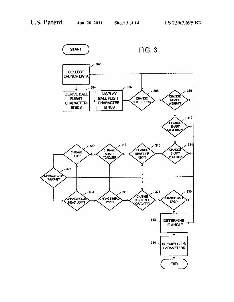
FIG. 3 is a flow chart illustrating an example method forcollecting launch data in accordance with one embodiment ofthe invention;
FIG. 4 is a diagram illustrating example components thatcan comprise a golf equipment fitting system configured inaccordance with one embodiment of the invention;
FIG. 5A is a diagram illustrating a double crest load patternfor a golfer's swing as determined by the process of FIG. 2;
FIG. 5B is a diagram illustrating a flat line load pattern fora golfer's swing as determined by the process of FIG. 2;
FIG. 5C is a diagram illustrating a single crest load patternfor a golfer's swing as determined by the process of FIG. 2;
FIG. 5D is a diagram illustrating an incline load pattern fora golfer's swing as determined by the process of FIG. 2;
FIG. 6 is a diagram illustrating an implementation of thesystem of FIG. 4 and the methods of FIGS. 1, 2, and 3;
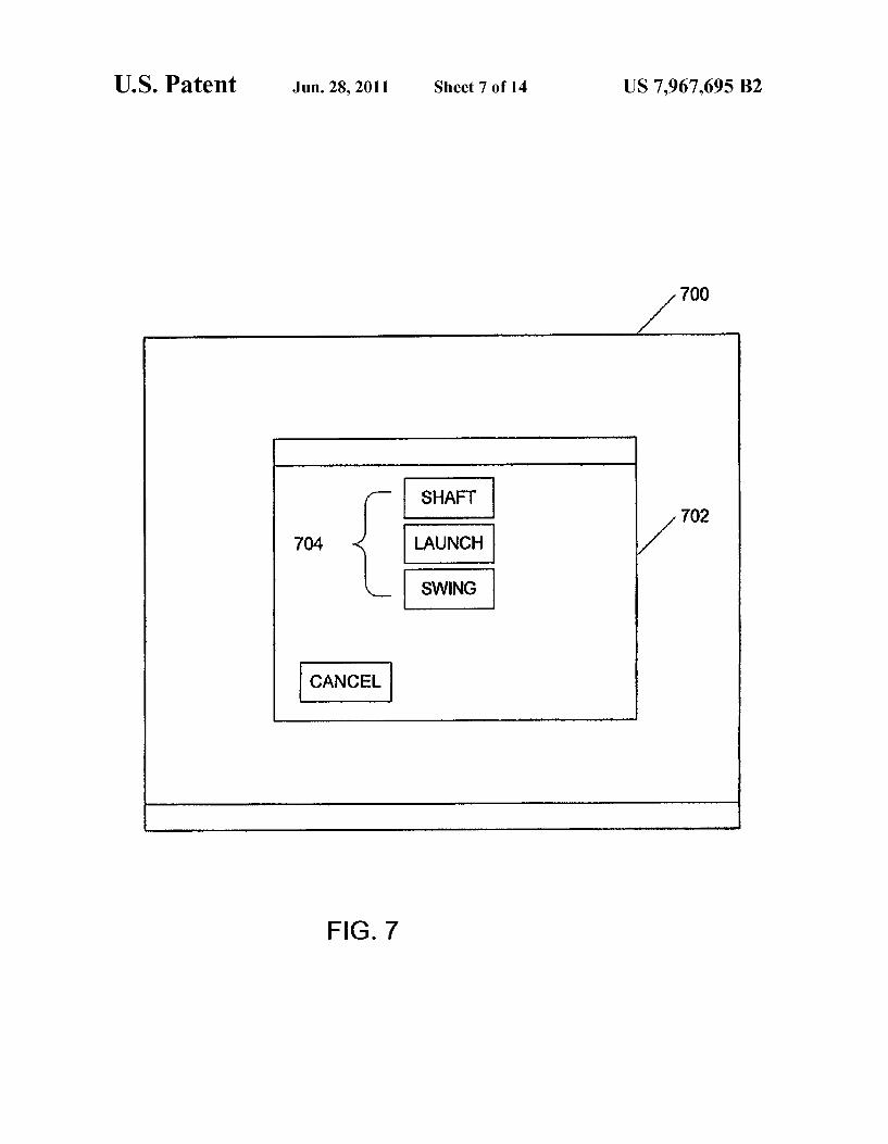
FIG. 7 is a screen shot illustrating an example openingscreen that can be displayed by the system of FIG. 4 to a userpreparing to implement the methods of FIGS. 1, 2, and 3;
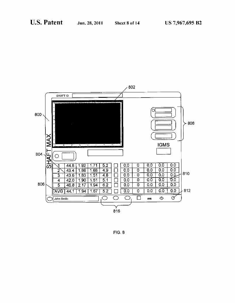
FIG. S is a screen shot illustrating an example shaft modulescreen that can be displayed by the system of FIG. 4 whenimplementing the method of FIG. 2;
FIG. 9 is a screen shot illustrating an example launchmodule screen that can be displayed by the system of FIG. 4when implementing the method of FIG. 3;
FIG. 10 is a screen shot illustrating an example optimiza-tion screen that can be displayed by the system of FIG. 4 tooptimize the data collected during implementation of themethod of FIG. 3;
FIG. 11 is a screen shot illustrating an example swingmodule screen that can be displayed by the system of FIG. 4when implementing the methods of FIGS. 1, 2, and 3;
FIG. 12 is a screen shot illustrating an example launchoptions screen that can be displayed by the system of FIG. 4when implementing the method of FIG. 3;
FIG. 13 is a screen shot illustrating an example systemsoptions screen that can be displayed by the system of FIG. 4when implementing the method of FIG. 1; and
FIG. 14 is a logical block diagram illustrating an exem-plary computer system that can be that can be used to imple-ment the system of FIG. 4.
DETAILED DESCRIPTION OF THE PREFERREDEMBODIMENTS
The golf equipment fitting process described herein can beimplemented as a multi-step evaluation process that can bebroadly divided into two phases. The first phase involves an

US 7,967,695 B2
evaluation of a golfer's current golf equipment and swingtechnique. The steps comprising the first phase require datacollection to give discreet information concerning keyattributes of the golfer's swing. The swing data gatheredduring the first phase can be used to identify major swingflaws so that these flaws can be corrected before fitting thegolfer with golf equipment. This can result in better fitting ofgolf equipment, because ifnot corrected, the swing flaws willlead to inconsistent results regardless of the equipment beingused. Moreover, if the golfer is fit for golf equipment based onhis flawed swing, the equipment he was fitted with may nolonger be appropriate if he later corrects the swing flaws.Thus, correcting swing flaws prior to beginning the clubfitting process can result in a more optimized fitting. To thisend, the systems and methods described herein can be used toaid in the identification and correction of swing flaws, whichcan be an integral part of the fitting process described below.
The second phase can involve collecting launch data and,in certain embodiments, combining it with swing data col-lected in the previous phase in order to fit the player withoptimized equipment including shafts, clubs, and balls.
Thus, FIG. 1 is a flow chart illustrating an example methodfor fitting golf equipment in accordance with one embodi-ment of the systems and methods described herein. Themethod of FIG. 1 begins in step 102 where the golfer isinterviewed in order to evaluate the current status of his golfgame. Step 102 can, for example, include determiningthrough the interview process: what equipment the golfershas been using; what the player considers to be the strengthsand weaknesses of his golf game; the courses and conditionsthe golfer will likely encounter; the level of competition thegolfer encounters; and an evaluation of the swing techniqueof the golfer.
Evaluating the swing technique of the golfer can compriseobserving the golfer hit several golf balls. Often, a videosystem, such as video system 414 described below, is used tohelp evaluate the golfer's swing technique using, forexample, a swing module 412, which is also described inmore detail below.
At this point, certain swing flaws can be readily apparent.These swing flaws can, in certain embodiments, be adjustedprior to proceeding. In this case, identification ofmore subtleswing flaws can occur at a later stage. Alternatively, evalua-tion of swing technique and identification of swing flaws, nomatter how apparent, can wait until swing evaluation, e.g. , asdescribed below in relation to step 106.
In step 104, the golfer's current golf clubs are evaluated.This evaluation can, for example, include measuring the flex,lie angle, and loft of the golfer's golf clubs. The flex can bemeasured using standard flex charts. The lie angle and loft arestandard measurements of the golf club. Briefly, however, ataddress, the club shaft and the ground create an angle calledthe lie angle. In this position, the club is perfectly square to thetarget. Another way to describe the lie angle is the angelbetween the centerline of the golf club shaft and the horizon-tal grooves on the clubface. The same lie angle does not suitall players. Physical differences, e.g. height, arm-length, etc.can require a different lie angle for one golfer compared toanother. Because proper lie angle is essential to achievingconsistently solid, accurate shots, it is important to measurethe lie angle of the golfer's clubs. If the golfer's lie angle is"toe up,
"he will tend to hook the ball, and will benefit from aflatter lie angle; if the golfer's lie angle is "toe down, "he willhave a tendency to slice the ball, and will benefit from a moreupright lie angle.
The loft is the angel that the golf club face makes relative tothe centerline of the shaft. Adjusting the loft of standard club
5
10
15
20
25
30
35
40
45
50
55
60
65
heads is an important method for compensating for the golf-er' s tendencies to hit higher or lower trajectories than normal.
Next, in step 106 the golfer' s swing is evaluated and data iscollected regarding the swing in step 10S.This swing data canthen be combined, in step 110,with the information gatheredin step 102 to generate a baseline performance matrix for the
golfer. The performance matrix can be used to help determineif the golfer's swing technique needs modification in step112.If it is determined that the golfer's technique needs to bemodified, then he can be given instruction in step 114.Theinstruction of step 114 should be designed to achieve specificmodifications in the golfer's swing technique that will helpthe golfer to achieve a more efficient swing. Progress can beclosely monitored, e.g. , by repeating steps 106-114 asrequired.
Because the process of FIG. 1 can involve swing techniqueevaluation and instruction, it can be preferable for steps 102-114 to be carried out by, or with the assistance of, a golfprofessional. In fact, it can be preferable for the entire golfequipment fitting process to be carried out by a golf profes-sional.
The swing evaluation and data collection of steps 106 and10S are described in more detail below in relation to the flowchart of FIG. 2.
Once it is determined, in step 112, that the golfer's tech-nique is sufficient, the data collected can be combined withlaunch data, in step 11S, to fit the golfer with optimizedequipment including shaft, club, and ball. The launch evalu-ation of step 11Sis described in more detail below in relationto the flow chart of FIG. 3.
The launch evaluation of step 11S can be followed byfurther swing evaluation (step 106).Alternatively, all swingevaluation steps can be completed prior to the launch evalu-
ation of step 11S.In either case, once the swing evaluation,step 106, and launch evolution 11S,are completed in step 116,then the resulting information can be used to specify param-eters that describe the optimum golf equipment for the golferin step 120.
FIG. 2 is a flow chart illustrating an example method forcollecting swing data in accordance with the systems andmethods described herein. First, in step 202 data related to theload time for the golfer's swing can be collected. The loadtime is defined as the time the golfer loads the shaft during hisdownswing. The loading starts just prior to, or at the top of,the golfer's back swing and ends at impact with the golf ball.The load time provides an indication of how quickly thegolfer swings a golf club from the top of his back swing toimpact with the golf ball. A load time that is too fast, or tooslow tends to be difficult to repeat and can result in many ofthe typical performance problems that golfers experience. Forexample, a load time that is too long generally results in a lackof power and inconsistent launch conditions. It has beenshown, using the systems and methods described, herein thatload time is generally optimized when it falls between 0.45 to0.50 seconds.
Next, in step 204, data related to the load pattern for thegolfer' s swing can be collected. The load pattern is defined asthe deflection, or load of the golf club shaft as a function oftime during the downswing. Different types of load patternsindicate different swing tendencies. For example, a "singlecrest" load pattern as shown in FIG. 5C indicates a swingwhere the golfer tends to release his wrist too early. Thissituation is often referred to as casting, i.e., the golfer iscasting the golf club much the same way a fishermen casts afishing rod. In FIG. 5C, the y-axis corresponds to the deflec-tion in inches, while the x-axis corresponds to time. The pointof impact with the golf ball corresponds to the point 506

US 7,967,695 B2
where the curve touches, or approaches, the x-axis. Thus, inFIG. 5C it can be seen from curve 510 that the golfer loadedthe club early in the golf swing, creating significant deflectionor load, but then released the load well before impact with thegolf ball.
Accordingly, a "single crest" load pattern is sometimessaid to indicate that the golfer loads the club too quickly at theinitiation of the downswing and then decelerates during therest of the downswing. A situation that is referred to as an"early load".
A "double crest" load pattern is illustrated in FIG. 5A. Adouble crest load pattern can indicate a situation where thegolfer initiates loading at the start of the downswing, as illus-
trated by crest 502, and then reloads the club with his wrist
just prior to impact, as illustrated by crest 504. This is indica-tive ofa golfer whose swing is not smooth and is typically toolong which again makes it di fficult to make consistent contactwith the golf ball.
A "flat line" load pattern is illustrated in FIG. 5B.The flatline load pattern can indicate a situation where the golfer haslittle or no significant load during the downswing as illus-
trated by load pattern curve 50S.A golfer with a flat line loadpattern does not generate enough energy to deflect the shaftand will not create solid or consistent contact with the golfball
The "incline" load pattern illustrated in FIG. 5D, on theother hand, is indicative of an optimum load pattern. Anincline load pattern is a linear loading, as illustrated by linearportion 512, of the shaft, where the crest load 514 occurs justprior to impact. A swing that results in an incline load patternmakes the most use of the stored energy in the shaft and istherefore the most efficient. Thus, it is preferable for thesystems and methods described herein to help modify thegolfer's swing and fit him with golf equipment that will
generate an incline load pattern swing after swing. In otherwords, the incline load pattern can be the model for thesystems and methods describe herein.
In step 206, swing parameters that define the gol fer' s swingcan be derived from the swing data collected in steps 202 and204. For example, in one embodiment, a load time can bederived from the load time data collected in step 202. The loadtime can be an average of the data collected for multipleswings. A peak load, or deflection, can also be derived fromthe load pattern data collected in step 204.Again the peak loadcan be averaged over several swings. A swing ramp can alsobe derived for the golfer. The swing ramp is a measure of thepotential energy of the swing and can be measured in milesper hour. Thus, it is similar to the club speed used in conven-tional techniques.
The data collected in steps 202 and 204, and derived there-from, can also be used to generate a shaft flex measurement.In other words, the load time, peak load, and swing ramp canbe correlated to a standard shaft flex measurement. This mea-surement can simply be a standard numerical indicator thatcorresponds to a certain standard shaft flex, i.e., stiff, regular,etc.
The swing parameters derived in step 206 can then bedisplayed in step 20S, e.g. , by system 400 described below.For example, the parameters derived in step 206 can be dis-played in conjunction with a graph of the load pattern of step204, i.e., the patterns of FIGS. 5A-5D. The displayed infor-mation can then be used to help evaluate the golfer's swing instep 210 and to identify any swing flaws using the informationdisplayed. For example, if the information displayed in step20S indicates that the golfer has a "single crest" load pattern,
6
10
16
20
26
30
36
40
46
60
66
60
66
then this can be identified in step 212 and instruction can begiven to the golfer to correct the early release, or casting, flawin the golfer's swing.
In certain embodiments, a video system, such as videosystem 414 can be used in conjunction with the swing datacollected in steps 202-206 and displayed in step 20S to ana-lyze the golfer's swing. Such a video system can comprisevideo, or high-speed cameras oriented, for example, directlybehind the golfer and pointed down the target line and/orfacing the golfer as he makes his swings. The images of thegolfer's swing generated by the video system can then bedisplayed and can be correlated to the load pattern. Thus,when the load pattern indicates a problem, the swing videocan be consulted to help assess the problem and to allow thegolfer to visualize the swing flaw and begin working to cor-rect it. Various swing flaws, which result in improper loadtime and load pattern, can then be corrected in step 214. Thisprocess, which is useful in modifying the golfer's techniquealso results in increased ball speed, appropriate launch angle,and spin rates.
As the golfer works to correct his swing in step 214, steps202-212 can be repeated until a more optimum swing isachieved. This results in a better swing and a better fitting thanconventional fitting techniques, because the golfer swing isimproved to the point where he can make better more consis-tent contact, rather than fitting the golfer for equipment whenhis swing has flaws that will prevent him from consistentlymaking contact even with his new fitted equipment.
Once the golfer's swing technique is sufficient to proceedwith the fitting process, a shaft stiffness recommendation canbe obtained from the swing parameters derived in step 20S.For example, the swing characteristics derived in step 20S canbe used to recommend shaft stiffness for the golfer.
Once the swing data is collected, the golfer's swing can beexamined to determine how he launches a golf ball. FIG. 3 isa flow chart illustrating an example for collecting launch datain accordance with one embodiment of the systems and meth-ods described herein. First, in step 302, launch data can becollected. In one embodiment, launch data is collected for thegolfer using the golfer's driver. Launch data can be collectedusing a high-speed camera system, such as a system 416,focused closely on the golf ball. The golf ball is then markedwith particular markings to allow launch data to be derivedfrom the high-speed pictures obtained from the high-speedcamera system. Launch data can include, e.g. , the initialvelocity of the golf ball as it is launched, the spin rate of thegolfball as it is launched, and the launch angle of the golfballrelative to the ground.
The spin rate can include components of backspin, side-spin, and rifle spin, each of which can be calculated depend-ing on the embodiment. The launch angle can also includeboth components of left/right deviation with the target lineand the angle with the horizon.
Once the launch data is collected in step 302, ball flightinformation can be derived in step 304 for each swing of thegolf club. For example, based on the images captured by thehigh speed camera system, the ball speed, spin, and launchangle can be derived as well as how far the ball would havecarried, an estimation of how far the ball would travel alltogether, i.e., including roll, and a deviation from the centerline. The deviation can be measured in degrees right or left ofthe centerline.
The information derived in step 304 can then be displayedin step 306, e.g. , by system 400. For example, not only can thevalues for the derived information be displayed, e.g. , in atable, but a graphical illustration of the ball flight can also bedisplayed.

US 7,967,695 B2
The process ofFIG. 3 can be started using the golfer's owndriver, or other equipment. The data collected can then beused to start fine-tuning the golfer' s equipment to achieve theoptimum ball flight, including a fine-tuning of the shaft rec-ommendation of step 216 described above. For example, inorder to maximize driver distance one needs to match thegolfer's ball speed with an optimized combination of launchangle and spin rate. Thus, after the golfer hits golf balls usinghis own club and data is collected and displayed in steps302-306, a club with a shaft flex in the range of that recom-mended in step 216 can be used to obtain and display moredate, i.e., steps 302-306 are repeated. The shaft flex can thenbe fined tuned in step 30S, by continuing to use clubs withvarious shaft flexes until a shaft flex that appears optimal isdetermined. In addition, different clubs, with various shaftmaterials, gram weights, tip sections, lengths, torques and canbe tested in steps 310-31S,and steps 302-306 repeated, untilan optimum ball flight is achieved as depicted, for example,by the data displayed in step 306.Various types of grips and
grip weights can also be tested in steps 320-322.It is well known that two different golf clubs can have the
same frequency, or flex range, but have entirely differentperformance characteristics. For example, a shaft can bestiffer in the tip, or stiffer in the butt, when compared toanother shaft. Torsional stiffness, or torque, can also play animportant part in the overall performance ofa golf club. Thus,although two different clubs can be well fitted to the golfer interms of shaft stiffness, they can produce entirely differentlaunch conditions. By finding the combination of shaft char-acteristics that maximizes, for example, distance off the tee,the golfer can be properly fitted with the best equipment forhis technique. In other words, by continually fine tuningvarious aspects of the golf shaft to achieve an optimal ballflight, the best equipment for the particular golfer can beidentified.
The driver is an important club for every golfer and hassome very specific characteristics that may need to beadjusted to obtain the best driver performance for a particulargolfer's technique. Accordingly, when fitting the golfer for adriver, various driver lofts (step 324), head types (step 326),and club head centers of gravity (step 32S) can be tested toarrive at an optimal driver ball flight characteristic. In addi-
tion, different ball types can be tested in step 330 to optimizedistance when using the driver. Different ball types havedifferent spin rates, which should be matched to the launchangle and the ball speed. For example, a higher spin rate cancause the ball to get higher in the air off the club face, whichcan reduce distance. On the other hand, in certain instances agolfer may need to increase the spin rate in order to gaindistance. Thus, the object of step 330 is to find the optimumspin characteristics for a particular golfer's ball flight trajec-tory and other characteristics. Often, the objective in driverfitting is to maximize distance, control, and consistency. Fit-ting the golfer to the appropriate shaft flex, driver lofts, shaftweights, ball type, club head type, center of gravity of clubhead, and shaft bend profiles can be intended to achieve ashigh a ball velocity as possible coupled with the appropriatelaunch angle and spin rate.
It should be noted that the process ofFIG. 3 can be repeatedfor all of the golfer's clubs including the driver, fairwaywoods, irons, wedges, and putters. Each type of golf clubresults in a unique set of issues that have to be addressed, oroptimized during the club fitting process. For the fairwaywoods and irons, for example, the target often is to have eachclub hit a certain distance with a high degree of repeatability.For the irons, each consecutive club in the set should have adistance gap between it and the next club so the golfer can
5
10
15
20
25
30
35
40
45
50
55
60
65
easily achieve hitting the ball from any distance to the target.Thus, the goal is more directed toward tight dispersion anddistance control rather than just distance. Therefore, the loftsof each club need to be set at the appropriate amount.
For wedges, the objective is to be able to achieve various
types of short game shots. Some types of shots require maxi-mum spin while others require higher launch angles. Thefitting process of FIG. 3 can be tailored to achieve perfor-mance evaluation for various wedge types that will optimizelofts, flanges, bounce angles, and other features necessary tomaster various shots that can be encountered by the golfer.
Several techniques can be used to further optimize the clubfitting process. For example, an optimum launch angle andspin rate can result in a ball flight that is too high, resulting ina loss of control. Thus, a maximum ball height can be used asa ceiling for the ball flight characteristics when testing variousequipment in steps 30S-330.For example, a good maximumceiling height for the ball to fly during a drive is 125 feet. Sothe goal can be to get as high a launch angle and as low abackspin as possible as long as the ball flight is less than 125ft. A trajectory model can then be used to predict the peakheight a ball flies for a given launch condition, as determinedin steps 302-306. A relationship that limits the launch angleand backspin for a given ball velocity so that the peak is lessthan 125 feet is then used when fitting the golfer with equip-ment. It should be noted that the maximum ceiling mightchange from golfer to golfer depending on the altitude andstandard weather conditions of the golf course that the golfertypically plays.
Further, the process of constantly changing aspects, i.e.,
shaft, ball, club head. etc. , and deriving new information eachtime can be very time consuming. To reduce the timerequired, a special type of club head can be used. Forexample, a driver head that can be manufactured to have thesame dimensions but different centers of gravity can be con-figured so that the driver head can be quickly assembled ontoa driver shaft. Different shafts, i.e., shafts of different mate-rials, lengths, gram weights, torques, etc. , and with differenttypes of grips and grip weights can then be maintained andconfigured to quickly assemble onto the driver head.
For example, in one embodiment, the driver head can beconfigured to quickly snap, or twists onto the end of a shaft.The driver head can be further configured to work in conjunc-tion with a fastener to ensure that the driver head stays on theshaft during testing. In one implementation, for example, ascrew, such as an Alan Head screw, can be inserted through ahole in the driver head and down into the shaft. The screw canthen be tightened to ensure the driver head remains secured tothe shaft.
Thus, a stable ofdifferent shafts comprising different char-acteristics, and of different driver club heads, comprisingdifferent loft angles and centers of gravity, can be maintainedso that they can be quickly assemble to create drivers withvarious characteristics for use, for example, during the fittingprocess of FIG. 3. It should be apparent that similar tech-niques can be extended to other clubs as well.
In step 332, the lie angle of the golfer's clubs can bemeasured using, e.g. , impact tape on the bottom of each club.This is often done for the irons and wedges. Thus, in step 332,the golfer can take equipment comprising characteristicsderived at steps 302-330 and hit balls using the tape. Theimpact tape can help determine if the club head is in a "toe-up" or "toe-down" position at impact. Adjustments in the lieangle can then be made until the golfer is striking the ballconstantly with the "sweet-spot" of the club face.
At this point, all of the information needed to fit the golferwith equipment that will result in optimum performance

US 7,967,695 B210
should be known and parameters associated with, or identi-
fying, the optimum equipment can be derived in step 334.In certain embodiments, the parameters of step 332 can be
used to identify specific clubs, and manufacturers, that shouldwork well for the golfer. The parameters can then be for-warded directly to the manufacturer as part of an order forcustomized clubs. Then, when the customized clubs arrive,they can be checked using the parameters to make sure theyare right and adjusted or returned as required.
FIG. 4 is a diagram of a golf equipment fitting systemconfigured in accordance with one embodiment of the sys-tems and methods described herein. In the example of FIG. 4,system 400 comprises three main components: a shaft-fittingcomponent 420; a launch fitting component 422 and a swingassessment component 424. In one embodiment, shaft-fittingcomponent 420 comprises a shaft module 40S and a wirelessreceiver 404. Wireless receiver 404 can be configured toreceive swing data from a wireless transmitter 402, which canbe interfaced with strain gauges coupled to a golf club shaftbeing swung by the golfer.
In conventional shaft fitting systems, strain gauges areoften wired to a system that collects swing data from the straingauges. The wires, however, can get in the way and impedethe golfer' s natural swing and thereby compromise the swingdata being collected. Using a wireless interface can helpeliminate this problem. In certain embodiments, wirelesstransmitter 402 can be interfaced with several strain gaugesdisposed along the shaft of the golf club. Often, the straingauges are disposed inside the shaft itself. Wireless transmit-ter 402 can, for example, be coupled with a strap configuredto strap the transmitter to the golfer's wrist. In such an imple-mentation, there can be wires coming from the end ofthe shaftto the wireless transmitter, which is strapped to the golfer'swrist. Thus, it is important to use enough wire so that wirelesstransmitter 402 does not interfere with the golfer's swing.
In an alternative embodiment, each strain gauge can becomprise its own wireless transmitter 402. For example, astrain gauge and wireless transmitter 402 can be included in asingle device installed inside the shaft. Alternatively, one ormore wireless transmitter can be inserted into the shaft, orotherwise disposed on the shaft and interfaced with one ormore strain gauges.
Swing data collected from the strain-gauged clubs, e.g. , viawireless receiver 404, can be used to help approximate theproper shaft flex and tip section recommendations as describeabove. The strain-gauged clubs not only measure how theshaft is loaded but also the deflection of the shaft during theswing. The collected swing data is then sent to shaft module40S for processing in accordance with the system sand meth-ods described herein. The processed data can then be turnedinto shaft recommendations. For example, the peak deflectionduring the downswing can indicate the proper shaft flex forthe golfer. The higher the peak load or deflection, the morestiff a shaft the golfer may need, e.g. , a golfer with a peakdeflection of greater than 4.5" can need a shaft that is S or Xflex. A golfer with a peak deflection of(3",on the other hand,canneeda L, A, orR fle shaft. AII others canneedan Ror Sflex shaft. Also, the thrust velocity of the shaft through impactcan be determined by shaft module 40S and used to determinean approximate shaft tip recommendation. A golfer with arelatively high thrust velocity of greater than 5 mph, forexample, can be biased toward a stiffer shaft.
Additional information such as a lead or lag deflection or atoe up or tow down deflection can be derived from the straingauges. Such information can indicate flaws in the golfer'sswing and therefore may be addressed earlier in the process,or they can indicate golf equipment recommendations. Ulti-
5
10
15
20
25
30
35
40
45
50
55
60
65
mately, an appropriate ratio of butt flex to tip flex, gramweight, and length can be determined by shaft module 40Susing the swing data collected via wireless receiver 404.
Launch fitting component 422 can, in one embodiment,comprise a high-speed camera system 416 and a launch mod-ule 410. High-speed camera system 416 can, for example,comprise a color CCD camera combined with a strobe unit.Conventional launch fitting systems often employ black andwhite cameras; however, this can limit the effectiveness of theclub fitting process, because the spin information obtained forthe golf ball after club impact can be less accurate thanrequired. This is because the software
configure
t process theblack and white images cannot always obtain the requisiteinformation with the accuracy required due to the nature ofthe black and white images.
By using a color high-speed camera, more accurate, ormore reliable launch data can be obtained. For example,because a color high-speed camera is used, markings com-prising two or more different colors, e.g. , blue and red, can beplaced on the golf ball and used to derive spin information.Images can, for example, be acquired by firing the strobe asthe golf ball is impacted and is launched from the clubface.High-speed camera system 416 can then be configured toacquire two images during this period. The two different colormarkings will be in a certain position in the first image, butwill have changed positions in the second image according tothe spin of the golf ball as well as the trajectory of the golfball.
Using digital signal processing techniques, for example,launch module 410 can be configured to derive the spin andlaunch information from the images capture by high-speedcamera system 416. It should be apparent that in a black andwhite system, the markings may not be easily discernable,thus rendering the information gathered in conventional sys-tems less accurate.
Swing assessment component 424 can comprise a videosystem 414 and a swing module 412. Video system 414 cancomprise one or more video cameras, or one or more high-speed cameras, depending on the implementation. Forexample, one video camera can be placed in front ofthe golferand one can be positioned down the target line of the golfer' s
swing. Images captured by the cameras are sent to swingmodule 412, which can process them and save them into astorage medium. The images can then be pulled up and dis-played. The images can be allowed to run, i.e., like a videostream so that the golfer can view his swing. The images canthen be used to assess the golfer's swing in association withthe information being gathered and displayed by shaft mod-ule 40S and launch module 410. To help in the assessment, itcan be preferable to allow the images to be paused, rewound,fast forwarded, etc.
It will be understood that shaft module 40S, launch module410, and swing module 412 can comprise the requisite hard-ware, so ftware, or combination thereof required to implementthe functions described above. Thus, each module can com-prise a standalone system. In alternative embodiments, how-ever, each module can comprise part of a larger system 406.For example, each module can comprise part of a softwareprogram loaded onto a single computer system. An exem-
plary computer system is described in more detail below. Butit should be noted that such a computer system can comprisecustomized hardware or software components or interfaces asrequired by a particular module.
For example, as illustrated in FIG. 6, system 400 can beadapted so that it can be included in a kiosk 600 with a display602 for displaying the information as described above. Thus,kiosk 600 can comprise a computer system configured to

US 7,967,695 B212
implement the functionality of shaft module 40S, launchmodule 410, and swing module 412.As can be seen, a golfer606 can stand on a mat 612 and make several swings. Thecomputer system included in kiosk 600 can then receiveswing data from strain gauges disposed on shaft 60S. Launchdata can be obtained from high-speed camera 604. The com-puter system can process the received data and generate infor-mation to be displayed on display 602.
Thus, for the first time launch information can be easily andreadily combined with other information, such as that pro-vided by shaft module 40S to more effectively fit the golferwith equipment. Moreover, images of the golfer's swing canbe acquired by swing module during the fitting process andused evaluate the golfer's swing. In this manner, flaws in thegolfer's swing, e.g. , as indicated by the launch or swing datacollected by launch module 410 and shaft module 40S respec-tively, can be viewed and hopefully corrected using theimages captured and displayed by swing analysis component424. Having all three components 420, 422, and 424 availablein the same system 400 makes fitting easier and more effec-tive. Further, as explained below, system 400 can be config-ured to allow a user to access information form each compo-nent 420, 422, and 424 as required during the fitting process.This makes fitting even more efficient and effective.
FIGS. 7-13are screen shots illustrating various screens thatcan be displayed on display 602. Thus, in FIG. 7 a screen shotof an opening screen 700 that can be displayed when a user,i.e., a golf pro preparing to fit a golfer with golf equipment,can see when they first run the software loaded onto thecomputer system included in kiosk 600. In screen 700, aselection window 702 is displayed that allows the user toaccess one of several functions, e.g. , via radio buttons 704.
The user can, for example, proceed past opening screen700 by electing to start a new fitting process using radiobuttons 704. This can cause a shaft module screen S00, suchas the one illustrated by the screen shot of FIG. S, to bedisplayed to the user. Shaft module screen S00 can be used todisplay the information generated by shaft module 40S.Thus,screen S00 can include a graphical display area S02 config-ured to display information related to the loading of a shaftbeing swung by a golfer being fitted for golf equipment using,e.g. , kiosk 600. The information displayed in area S02 cancomprise curves, such as those depicted in FIGS. 5A through5D, for each swing. The curves being displayed in area S02can be used to assess the golfer's swing in order to help thegolfer make needed swing improvements to optimize thefitting process.
Additionally, screen S00 can include a table S04 in whichswing parameters, e.g. , time, peak flex, ramp potential, andcorresponding flex, derived for each swing can be displayed.In the example of FIG. S, data can be displayed for theprevious 5 swings. The bottom row S06 of table S04 can beused to display averages for the values displayed in the table.The average values can be used, for example, to make shaftrecommendations for use in the rest of the fitting process asdescribed above and as further illustrated below.
Screen S00 can also include a table S10 that can be used todisplay information obtained during launch analysisdescribed below. Thus, the user can have launch analysisinformation available in order to help the user recommend ashaft or analyze the golfer's swing. As can be seen, in theexample of FIG. S, the launch data for the previous 5 swingscan be displayed in table S10.Further, screen S00 can includea toolbar S12, with radio buttons S16 that allow the user toquickly jump from shaft module screen S00 to the launchmodule screen 900 and to swing module screen 1100.Screens900 and 1100 are described below, but the ability to quickly
6
10
16
20
26
30
36
40
46
60
66
60
66
access these screens allow the user to more effectively use allthe tools available to analyze the golfer's swing in order toarrive at an optimal equipment fitting recommendation.
Screen 900, illustrated in the screen shot of FIG. 9, canactually be displayed by launch module 410 while launchdata is being gathered. Thus, screen 900 can comprise a table910 for displaying the launch informationbeing derived, e g. ,ball speed, spin, launch angle, carry distance, and total dis-tance. Additionally, table 910 can comprise columns 906 fordata related to the deviation of the ball flight from the center,or target line. Thus, columns 906 can be used to display adeviation from the centerline in degrees as well as side spininformation.
Table 910 can also include a row 91S in which averages forthe values displayed in table 910 can be displayed. Forexample, in the embodiment ofFIG. 9, column 91S is used todisplay averages for the previous 7 swings. The informationfrom table 910 can then be propagated to screen S00 in tableS10.Thus, depending on the number of columns in table 910,some or all of the launch data from screen 900 can also bedisplayed in screen S00, with the ability to quickly jump fromone screen to the other using radio buttons S16.
Screen 900 can also include a graphic data area 914 fordisplaying graphical information related to ball flight asderived, e.g. , by launch module 410.Thus, a graph of the ballfight illustrating height, e.g. , in feet, and distance, e.g. , inyards, can be displayed in area 914. Additionally, anothergraphical area 912 can be included to graphically illustratethe deviation from the centerline. Thus, area 912 can beconfigured to graphically illustrate a distance, e.g. , in yards,and a deviation, e.g. , in degrees. Radio control buttons 904can be included to allow the user to graphically display, inareas 914 and 912, data for each swing, a particular swingsuch as the last swing, the average of all swings, etc. Similarcontrol buttons SOS can be included in screen S00.
Screen 900 can also include a tool bar 902 in which infor-mation related to the equipment currently being used can bedisplayed. Thus, the golfer can make a few swings and launchdata can be gathered and displayed on screen 900. Based onthe information, the user can suggest equipment changes, i.e.,a lower spinning ball, a stiffer shaft, etc. and new data can beacquired and displayed. Each time equipment, or aspects ofthe equipment, is changed, the information in toolbar 902 canbe updated. This way, neither the user, nor the golfer, isrequired to remember what equipment they are currentlyusing. This is helpful, because the golfer can make severalequipment changes, based on the launch information beingcollected and displayed, until an optimum ball flight isachieved.
A launch optimization screen 1000, as illustrated in FIG.10, can even be invoked to help optimize the launch databeing collected. Thus, for example, launch optimizationscreen can be used to quickly assess the optimum launchconditions for a certain golfer based on information collectedby launch module 410.
Swing module screen 1100, an example of which is illus-trated by the screen shot of FIG. 1, can be included to allowthe user and the golfer to view the images captured by videosystem 414 and processed by swing module 412.Screen 1100can, as illustrated in the example of FIG. 11, comprise twohalves, with each half comprising a video display area 1102and 1106 and control areas 1104 and 110S respectively. InFIG. 11, the controls comprising control area 1104 can beused to play, freeze, rewind, fast forward, etc. the imagesbeing displayed in video display area 1102 in much the sameway VCR controls work. Video display area 1106can displayreal time images. The images being displayed can, in certain

13US 7,967,695 B2
14embodiments, be switched from one camera making up videosystem 414 to the next. Further, in certain embodiments, onehalf of screen 1000 can be used to display images from onecamera, while the other half is use to display images fromanother camera.
Launch options screen 1200, illustrated by the examplescreen shot ofFIG. 12, can be used to enter information aboutthe equipment presently being used in conjunction with gath-ering launch data to be displayed in screen 900.
Options screen 1300 can be included to display informa-tion related to each of screen S00, 900, and 1100 simulta-neously. Thus, screen 1300 can comprise a shaft area 1302 inwhich controls for the operation of shaft module 40S can bemanipulated. Similarly, screen 1300 can comprise launcharea 1304 and swing area 1306 in which controls for theoperation of launch module 410 and swing module 412,respectively, can be manipulated.
Thus, the fitting processes and techniques described abovecan be implemented via a kiosk, such as kiosk 600, usingscreens such as those just described. As mentioned, modules40S, 410, and 412 can be implemented as software modules,possibly with associated specialized hardware interfaces,within a computer system in kiosk 600. In other words, kiosk600 can comprise a computer system loaded with softwaremodules 40S, 410, and 412.FIG. 14 is a logical block diagramillustrating an example embodiment of a computer system1400 that can be used to implement the system of FIG. 4.
As will be understood, some type of processing system isalways at the heart of any computer system, whether theprocessing system includes one or several processorsincluded in one or several devices. Thus, computer system1400 of FIG. 14 is presented as a simple example of a pro-cessing system. In the example of FIG. 14, computer system1400 comprises a processor 1410 configured to control theoperation of computer system 1400, memory 1404, storage1406, a Input/Output (I/O) interfaces 140S, a display output1412, a user interface 1414, and a bus 1402 configured tointerface the various components comprising computer sys-tem 1400.
Processor 1410, in one embodiment, comprises a pluralityof processing circuits, such as math coprocessor, networkprocessors, digital signal processors, audio processors, etc.These various circuits can, depending on the embodiment, beincluded in a single device or multiple devices. Processor1410also comprise an execution area into which instructionsstored in memory 1404 are loaded and executed by processor1410 in order to control the operation of computer system1400. Thus, for example, by executing instructions stored inmemory 1404, processor 1410 can be configured to imple-ment the functionality of modules 40S, 410, and 412.
Memory 1404 can comprise a main memory configured tostore the instructions just referred to. In one embodiment,memory 1404 can also comprise a secondary memory used totemporarily store instructions or to store information inputinto computer system 1400, i.e., memory 1404 can act asscratch memory also. Memory 1404 can comprise, dependingon the embodiment, a plurality ofmemory circuits, which canbe included as a single device, or as a plurality of devices.
Storage 1406 can include, in certain embodiments, a plu-rality ofdrives configured to receive various electronic media.For example, in one embodiment, storage 1406 includes a
floppy drive configured to receive a floppy disk, a compactdisk drive configured to receive a compact disk, and/or adigital video disk drive configured to receive a digital video-disk. In another embodiment, storage 1406 can also includedisk drives, which can include removable disk drives. Thedrives included in storage 1406 can be used, for example, to
5
10
15
20
25
30
35
40
45
50
55
60
65
receive electronic media that has stored thereon instructionsto be loaded into memory 1404 and used by processor 1410tocontrol the operation of computer system 1400.
I/O interfaces 140S can be configured to allow computersystem 1400 to interface with devices such as video system414, high-speed camera system 416, and receiver 404. Thus,I/O interface 140S can comprise the interface hardwarerequired to receive signals from the various components usedto collect the data used by modules 40S, 410, and 412.
Display interface 1412 can be configured to allow com-puter system 1400 to interface with a display. Thus, computersystem 1400 can display the information, described in rela-tion to the example screen shots described above, to a user viadisplay interface 1412.
User interface 1414 can be configured to allow a user tointerface with computer system 1400.Thus, depending on theembodiment, user interface 1414 can include a mouse inter-
face, a keyboard interface, an audio interface, etc.It should be clear that the general description ofa computer
system provided above is by way ofexample only and shouldnot be seen to limit implementation of system 400 to anyparticular computer architecture or implementation. Ratherany architecture or implementation capable of implementingthe processes and functionality described above can be usedto implement the systems and methods described herein.
While certain embodiments of the inventions have beendescribed above, it will be understood that the embodimentsdescribed are by way of example only. Accordingly, theinventions should not be limited based on the describedembodiments. Rather, the scope of the inventions describedherein should only be limited in light of the claims that followwhen taken in conjunction with the above description andaccompanying drawings.
The invention claimed is:1.A method for fitting a golfer with golf equipment, com-
prising:in a launch module, receiving launch data from a launch
monitor related to how a golfer strikes a golf ball usinga golf club;
in the launch module, using the received launch data tooptimize a launch angle, velocity and spin rate relative toeach other, wherein optimizing the launch angle, veloc-ity, and spin rate comprises matching the velocity with acombination of launch angle and spin rate to achievemaximum distance and control when hitting a golf ball,and transforming the data for display on a display; and
selecting a maximum ceiling height for golf ball trajectorythat is not based on how the specific golfer hits the golfball, and wherein matching the velocity with a combi-nation of launch angle and spin rate comprises matchingvelocity with a combination of launch angle and spinrate determined based at least in part on the maximumceiling height, wherein said optimizing the launch angle,velocity, and spin rate and said matching velocity and acombination of launch angle and spin rate determinedbased at least in part on the maximum ceiling height areperformed in computer having a processor.
2. The method of claim 1, further comprising displayinginformation related to the received launch data.
3. The method of claim 2, wherein the information is dis-played in a graphical format.
4. A method for fitting a golfer with golf equipment, com-prising:
in a launch module, receiving launch data obtained when agolfer swings a first shaft and club head combination;
in the launch module, optimizing a launch angle, velocityand spin rate relative to each other based on the launch

15US 7,967,695 B2
16data, wherein optimizing the launch angle, velocity, andspin rate comprises matching the velocity with a com-bination of launch angle and spin rate to achieve maxi-mum distance and control when hitting a golf ball;
iteratively changing a combination of characteristics of at s
least one of the shaft and the club head until the opti-mized launch angle, velocity and spin rate are achieved;and
selecting a maximum ceiling height for golf ball trajectorythat is not based on how the specific golfer hits the golf to
ball, and wherein matching the velocity with a combi-nation of launch angle and spin rate comprises matchingvelocity with a combination of launch angle and spinrate determined based at least in part on the maximumceiling height, wherein said optimizing the launch angle, tsvelocity, and spin rate and said matching velocity and acombination of launch angle and spin rate determinedbased at least in part on the maximum ceiling height areperformed in computer having a processor.
5. The method ofclaim 4, wherein the launch data includeslaunch monitor data obtained from a launch monitor.
6. The method of claim 4, further comprising:receiving launch data obtained when a golfer swings a
second shaft and club head combination formed afterchanging a combination ofcharacteristics ofat least oneof the shaft and the club head;
optimizing a launch angle, velocity and spin rate relative toeach other based on the launch data, wherein optimizingthe launch angle, velocity, and spin rate comprisesmatching the velocity with a combination of launchangle and spin rate to achieve maximum distance andcontrol when hitting a golf ball; and
further changing a combination ofcharacteristics ofat leastone of the shaft and the club head to achieve the opti-mized launch angle, velocity and spin rate thereby form-
ing a third club head and shaft combination.