united states district court district of...
TRANSCRIPT

UNITED STATES DISTRICT COURT DISTRICT OF SOUTH DAKOTA
CENTRAL DIVISION
Verizon Wireless (VAW) LLC, et al.,
Plaintiff,
vs.
Bob Sahr, et al.,
Defendants and Intervenors.
Civil Number 04-3 0 14
AFFIDAVIT OF JEFF HARMON
STATE OF CALIFORNIA 1 ) ss.
COUNTY OF CONTRA COSTA )
1. My name is Jeff Harmon. I am a member of Technical Staff in the Network
Planning Department for Verizon Wireless. My job responsibilities include monitoring usage on
portions of the Verizon Wireless SS7 network and planning growth in network capacity. I
interact with vendors to design and implement software changes to provide required features and
capabilities in the Verizon Wireless SS7 network.
2. I. make this Affidavit in support of Verizon Wireless' motion for summary
judgment. These matters are within my personal knowledge based on my job responsibilities
with Verizon Wireless, or are based on my review of company business records maintained in
the ordinary course of business.
3. I worked for Bell System companies beginning in February 1965. Between 1989
and 1997 I worked for Pacific Bell in its signaling engineering group in San Ramon CA., and
was responsible for SS7 interconnection testing with other carriers, and developed test scripts
designed to determine compliance with standards of interconnecting signaling systems. In 1997

I began working for AirTouch Cellular in the SS7 planning group, and then became an SS7
network planner for Verizon Wireless starting in 2000.
4. In my positions, beginning in 1989, I have been responsible for becoming familiar
with the structure, architecture, purpose, and formatting of SS7 signaling. I have been
responsible for understanding and implementing standards for signaling at Pacific Bell,
AirTouch Cellular, and Verizon Wireless.
5. I have attended industry seminars and classes addressing SS7 and other signaling
issues, and have participated in industry sub-committees addressing the development of SS7
signaling standards. In my position with Verizon Wireless I have been responsible for the
deployment of the Jurisdiction Information Parameter in all Verizon Wireless mobile switching
centers.
6. A commonly accepted industry standard protocol for delivering signaling
information between telecommunications service providers is referred to as Signaling System 7
or "SS7." SS7 is the most common signaling protocol used in the industry. Verizon Wireless
utilizes SS7 throughout its South Dakota network.
7. SS7 provides carriers the ability to exchange information necessary to establish
the voice path so that a call can be completed. SS7 messages are delivered on a physically
separate network from the calls themselves.
8. To deliver signaling information using SS7 protocol, a carrier must: a) obtain the
information to be transmitted, b) categorize the information in a way that will be understood by
carriers receiving the information, and c) deliver the information.
9. Because Verizon Wireless operates some cell towers that serve across MTA
and/or state boundaries, Verizon Wireless could identify the MTA or state in which the call
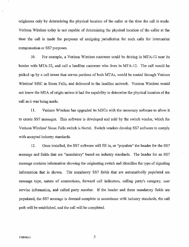
originates only by determining the physical location of the caller at the time the call is made.
Verizon Wireless today is not capable of determining the physical location of the caller at the
time the call is made for purposes of assigning jurisdiction for such calls for intercanier
compensation or SS7 purposes.
10. For example, a Verizon Wireless customer could be driving in MTA-12 near its
border with MTA-32, and call a landline customer who lives in MTA-12. The call would be
picked up by a cell tower that serves portions of both MTAs, would be routed through Verizon
Wireless' MSC in Sioux Falls, and delivered to the landline network. Verizon Wireless would
not know the MTA of origin unless it had the capability to determine the physical location of the
call as it was being made.
11. Verizon Wireless has upgraded its MSCs with the necessary software to allow it
to create SS7 messages. This software is developed and sold by the switch vendor, which for
Verizon Wireless' Sioux Falls switch is Nortel. Switch vendors develop SS7 software to comply
with accepted industry standards.
12. Once installed, the SS7 software will fill in, or "populate" the header for the SS7
message and fields that are "mandatory" based on industry standards. The header for an SS7
message contains information showing the originating switch and identifies the type of signaling
information that is shown. The mandatory SS7 fields that are automatically populated are
message type, nature of connections, forward call indicators, calling party's category, user
service information, and called party number. If the header and these mandatory fields are
populated, the SS7 message is deemed complete in accordance with industry standards, the call
path will be established, and the call will be completed.

13. Neither the information in the header nor the information in the mandatory SS7
fields will tell the terminating carrier whether a wireless call is intraMTA, interMTA and
intrastate, or interMTA and interstate.
14. There are also a number of SS7 fields that are considered to be "optional" in
accordance with industry standards. This means that they can be populated, but they are not
required to establish a voice path and complete a call. Optional fields are not automatically
populated, but the SS7 software can be manually programmed to populate optional fields.
15. One optional field in the SS7 message is the calling party's number. Verizon
Wireless populates this field, but that will not tell a terminating carrier whether the wireless call
is intraMTA, interMTA and intrastate, or interMTA and interstate.
16. A second optional field is the Jurisdictional Information Parameter or ("JIP")
field, which is populated with a six-digit number.
17. Verizon Wireless populates the JIP field in a manner that is consistent with
industry standards developed through the Alliance for Telecommunications Industry Solutions
("ATIS") Network Interconnection Interoperability Forum ("NIIF"). ATIS is a technical
planning and standards development organization, and its membership includes large and small
LECs, long distance carriers, wireless carriers, and equipment vendors. Approved ATIS
standards are considered to be industry standards.
18. On December 15, 2004, the NIIF released a standards document that includes,
among other things, rules on how wireless carriers are to populate the JIP field. ATIS-0300011,
Network Interconnection Interoperability (NIIF) Refirence Document, Part III, Installation and
Maintenance Responsibilities for SS7 Linh and Trunks, p. 21 (attached as Exhibit JH-1). These
rules provide that the JIP should be populated "where technically feasible" with an NPA-NXX

that is assigned in the LERG to the originating switch or MSC." An NPA-NXX is industry
shorthand for the area code and prefix for a block of 10,000 phone numbers. The LERG is the
Local Exchange Routing Guide, which carriers use to determine how to route calls. When
Verizon Wireless is assigned a block of 10,000 phone numbers, it associates that NPA-NXX
with its MSC in the LERG.
19. Verizon Wireless populates the JIP field with a six-digit code associated with its
Sioux Falls MSC. As a result, all calls originated under control of the Sioux Falls MSC will
have the same JIP. This will tell the terminating carrier that Verizon Wireless originated the call,
and that it was originated on the Sioux Falls MSC, but will not provide the terminating carrier
with information that will show the call to be intraMTA, interMTA and intrastate, or interMTA
and interstate.
20. There is no industry-standard SS7 field that Verizon Wireless could use to
identify whether a call is intraMTA, interMTA and intrastate, or interMTA and interstate. As a
result, even if Verizon Wireless could identify the originating MTA or state of a call, there would
be no way to format that information within an SS7 message in a way that would communicate
this to other telecommunications providers in accordance with industry standards.
AFFIANT SAYS NOTHING FURTHER.
STATE OF CALIFORNIA 1 ) ss.
COUNTY OF
On ~ D V W b V 1 1 ! ,&ms , 2005, before me, ,>& 0 -q M - GG v l ~ , personally appeared Jeff Harmon,
personally known to me
I$ provided to me on the basis of satisfactory evidence
to be the person whose name is subscribed to the within instrument and acknowledged to me that he executed the same in his authorized capacity, and that by his signature on the instrument the person, or entity upon behalf of which the person acted, executed the instrument.
WITNESS my name and official seal.
~ i z a t u r e of Notary Public

Network Interconnection lnteroperability (NII F) Reference Document
Part Ill, Installation and Maintenance Responsibilities for SS7 Links and Trunks
(formerly NllF 501 8)
EXHIBIT JH-1

ATIS is a technical planning and standards development organization that is committed to rapidly developing and promoting technical and operations standards for the communications and related information technologies industry worldwide using a pragmatic, flexible and open approach. Over 1,100 participants £rom more than 350 communications companies are active in ATIS' 21 industry committees, and its Incubator Solutions Program. < http:llwww.atis.or~l >
Notice This document was developed by the Alliance for Telecommunications lndustry Solutions' (ATIS) sponsored Network Interconnection lnteroperability Forum (NIIF). The NllF provides an open forum to encourage the discussion and resolution, on a voluntary basis, of industry- wide issues associated with telecommunications network interconnection and interoperability which involve network architecture, management, testing and operations and facilitates the exchange of information concerning these topics. The NllF is responsible for identifying and incorporating the necessary changes into this document. All changes to this document shall be made through the NllF issue resolution process as set forth in the NllF Principles and Procedures. This document is maintained and exclusively distributed by ATlS on behalf of the NIIF.
Note Regarding Previous Versions The NllF Reference Document was formerly known as the Network Operations Forum (NOF) Reference Document. The NOF Reference Document was published and maintained by Bellcore. The last version of the NOF Reference Document is Issue 13.
Disclaimer and Limitation of Liability The information provided in this document is directed solely to professionals who have the appropriate degree of experience to understand and interpret its contents in accordance with generally accepted engineering or other professional standards and applicable regulations. No recommendation as to products or vendors is made or should be implied. NO REPRESENTATION OR WARRANTY IS MADE THAT THE INFORMATION IS TECHNICALLY ACCURATE OR SUFFICIENT OR CONFORMS TO ANY STATUTE, GOVERNMENTAL RULE OR REGULATION, AND FURTHER NO REPRESENTATION OR WARRANTY IS MADE OF MERCHANTABILITY OR FITNESS FOR ANY PARTICULAR PURPOSE OR AGAINST INFRINGEMENT OF INTELLECTUAL PROPERTY RIGHTS. ATlS SHALL NOT BE LIABLE, BEYOND THE AMOUNT OF ANY SUM RECEIVED IN PAYMENT BY ATlS FORTHIS DOCUMENT, WITH RESPECT TO ANY CLAIM, AND IN NO EVENT SHALL ATlS BE LIABLE FOR LOST PROFITS OR OTHER INCIDENTAL OR CONSEQUENTIAL DAMAGES. ATlS EXPRESSLY ADVISES THAT ANY AND ALL USE OF OR RELIANCE UPON THE INFORMATION PROVIDED IN THIS DOCUMENT IS AT THE RISK OF THE USER.
ATIS-030001 I , NllF Reference Document, Part 111, Installation and Maintenance Responsibilities for SS7 Links and Trunks
The NIIF Reference Document, Part 111, Installation and Maintenance Responsibilities for SS7 Links and Trunlrs is an ATIS standard developed by the NIIF under the ATIS OAM& P Functional Group.
Published by Alliance for Telecommunications Industry Solutions 1200 G Street, NW, Suite 500 Washington, DC 20005
Copyright O 2004 by Alliance for Telecommunications Industry Solutions All rights reserved.
No part of this publication may be reproduced in any form, in an electronic retrieval system or otherwise, without the prior written permission of the publisher. For information contact ATlS at 202.628.6380. ATlS is online at < http:llwww.atis.org >.
Printed in the United States of America.

INSTALLATION. TESTING & MAINTENANCE RESPONSIBILITIES FOR SS7 LINKS AND TRUNKS
Table of Contents
GENERAL ................................................................................................................................................... 4
LINK RESPONSIBILITIES ............................................................................................................................ 5 A . SS7 Link Control .............................................................................................................................. 5
..................................................................................................... B . Access Service Customer (ASC) 5 ....................................................................................................... C . Access Service Provider (ASP) 6
......................................................................................................................... D . LINK DEFINITIONS 7 E . Link Augmentation ........................................................................................................................... 7 F . Diversity ......................................................................................................................................... 7 G . Catastrophic SS7 Network Failures ............................................................................................... 10
LINK INSTALLATION ........................................................................................................................... 10 ..................................................................................... A . Signaling Point of Interconnection (SPOI) 10
B . Pre-service Testing ........................................................................................................................ 10 ....................................................................................... C . Acceptance Tests For SS7 Link Circuits 10
D . ASP Prove In Period ...................................................................................................................... 10 E . Synchronization ............................................................................................................................. 10
...................................................................................................................... F . Compatibility Testing 11 ................................................................ G . Test Severity Analysis Criteria - Part Ill (Attachment D) 11
H . Completions ............................................................................................................................... 12 I . Rearrangements ............................................................................................................................ 12 J . Timer Values ............................................................................................................................... 12
LINK MAINTENANCE ................................................................................................................................. 12 A . Trouble Reporting .......................................................................................................................... 12
........................................................................................................... B . Sectionalization and Repair 13 .............................................................. C . Maintenance of SS7 Links Within a Higher Rate Facility 13
D . Trouble Clearance ................................................................................................................... 13 ....................................................... E . ASP Node To ASC Node Interconnect Testing And Analysis 14
...................................................................................................................... TRUNK RESPONSIBILITIES 14 ............................................................................................. A . Access Service Customer ASCIASP 14
............................................................................... B . Conversion of Multi-frequency Trunks to SS7 14 C . Trunk Circuit Identification Code (TCIC) ........................................................................................ 18
............................................................. D . Trunk Circuit Identification Code (TCIC) Numbering Plan 18 E . Tones and Announcements ......................................................................................................... 18
............................................................................................................ F . Trouble Report Disposition 19
TRUNK INSTALLATION ........................................................................................................................... 19 ..................................................................... A . Point of Presence (POP) Serving Multiple Switches 19
.............................................................................. TRUNK TROUBLE DETECTION RESPONSIBILITIES 19
......................................................................................................... SCREENING AND TRANSLATIONS 19 .......................................................................................... A . Final Global Title Translations (FGTT) 19
B . Translation Types .......................................................................................................................... 20 C . TCAP Transaction Looping ............................................................................................................ 20
Rules for Populating JIP ............................................................................................................................. 21
SS7 NETWORK SECURITY BASE GUIDELINES .................................................................................... 21
SS7 SOFTWARE VALIDATION ................................................................................................................. 22

............................................................................... 12 . DUAL STP FAILURE PREVENTION PROCEDURES 22
13 . COMBINED NODE . MINIMUM SET OF GUIDELINES ......................................................................... 22 .................................................................................................................................... A . Architecture 22
............................................................................................................. B . Routing And Configuration 23 C . Network Management .................................................................................................................... 23 D . Diversity ......................................................................................................................................... 23 E . Testing ........................................................................................................................................... 23

I. GENERAL
This document outlines Access Service Customer (ASC) and Access Service Provider (ASP) responsibilities for the Signaling System 7 (SS7) interface between carriers. It deals with the physical interconnecting trunks and link(s) as well as the software necessary to support the use of the link(s) to transport SS7 messages between carriers. It is intended to be a living document to aid operations work forces. It does not replace or supersede Tariffs, Contracts or any other legally binding documents. It is limited to procedures relating to the installation and maintenance of the SS7 trunks and link(s) and associated software used to interconnect and provide services between lnterexchange and Access Service Providers. All networks which connect to ASCs and ASPS via SS7, should be expected to recognize these operational guidelines, as providers of public switched services regardless of whether or not they provide Public Switched Telephone Network services. For the purpose of this document, the terms, SS7 and CCS are interchangeable.
The ASC, for the purposes of this document, is defined as the lnterexchange Customer engaged for hire between two or more exchanges, including interstate or foreign communication by wire or radio.
The ASP, for purposes of this document, denotes a company engaged in the business of furnishing access service in a franchised territory.
The Wireless Service Provider (WSP), for the purposes of this document, is defined as those carriers engaged in lntrallnterstate communication via radio frequency.
Local Service Provider (LSP) is defined as the Local Exchange Carrier (LEC) selling local interconnection service arrangement trunk(s) to another LEC.
Local Service Customer (LSC) is defined as the LEC purchasing local interconnection service arrangement trunk(s) from another LEC.
Where ASPIASC interconnection statements are made or identified, specific to their purpose, WSPILSPILSC may be substituted as appropriate.
In addition to other operational and technical agreements made at the Network Interconnection lnteroperability Forum, this document is being reissued to incorporate the following changes:
Standardization of the Issue Number and publication date to agree with other sections of the NllF Reference Document. Addition of a new Part Ill Attachment G - titled SS7 Diversity Validation Guidelines Addition of new document Part Ill Attachment H - titled "SS7 Cause Codes & Tones and Announcements."
The SS7 link(s) may be considered as a network enhancement for certain existing services between lnterexchange and Access Service Providers as well as providing a transport to new services.
The term node is used in this document to mean any SS7 capable network element without regard to its specific function i.e. Signal Transfer Point (STP), Signal Point (SP), Service Switching Point (SSP), Service Control Point (SCP).
The software resident programs, in both ASP and ASC interconnecting nodes for the purpose of providing services transported on SS7 link(s), will be referred to as applications.
The NllF has developed the following guidelines outlining the medium by which internetwork affecting maintenance activity notification will be provided to the interconnected company and the time frame prior to the planned activity:
Notification when possible should be made at least 5 working days prior to the planned change activity. Notification should be made in the form of:
- E-Mail (recommended where available), - FAX or,

- Telephone call. Notification should be provided to the affected company's appropriate notification center. Contact information is included in the NllF Company Specific Contact Directory. An example of a notification form is located in the NM Section, Part VI, of the NllF Reference Document.
When network modifications are planned to any SS7 network element that has the potential of affecting traffic, the ASPIASC must notify the interconnecting carrier(s) of the planned change. Sufficient information should be exchanged to ensure that all parties understand:
Affected Network Element Date and time of change Expected duration Traffic effect during change Potential hazards
Compatibility test requirements and procedures should be considered.
The need exists to install and maintain time of day clock settings to coordinated universal time standards for SS7 network elements. In the absence of automated clock update standards and systems, it will be necessary to manually install and maintain time of day clock settings, as follows:
Internal Network Element (NE) clocks set to + or - 15 seconds from the Coordinated Universal Time (UTC) minute register would degrade service.
Daily routine to check NE clock (e.g., 8 am) to UTC.
Weekly routine to check clock source to National Institute of Science and Technology (NIST), e.g., WWV, Naval Observatory. etc., to nearest second + or - 1 seconds.
Upon initialization of NE (boot) there is a need to load time of day, otherwise NE sets to 0000 hours 1/1/00 - (operationally sensitive.)
LINK RESPONSIBILITIES
SS7 Link Control
The ASC will have overall responsibility for the installation and maintenance of the SS7 link(s). The designation of an ASC as having overall responsibility does not relieve the ASP of the responsibility for taking prompt appropriate actions needed to correct an identified failure condition. The ASPS and ASCs are responsible for the portion of an SS7 link, which they maintain.
The ASP is responsible for ensuring that its portion of the SS7 link(s) provided to the ASC are installed and functioning properly. In addition, the ASP should work cooperatively with the ASC to perform SS7 protocol tests to ensure the ability of the interfaces to correctly transmit and respond to SS7 messages being passed between carriers.
B. Access Service Customer (ASC)
The following are the responsibilities of the ASC:
Provides trained personnel
Designates a Control office(s) for the overall responsibility for SS7 link(s).
Cooperates with the ASP to ensure that the SS7 link(s) are installed in accordance with the ASCs service request.

Notifies the appropriate ASP Interexchange Customer Service Center (ICSC or equivalent) when the service due date is to be changed.
Sectionalizes troubles to determine if the trouble is located in its facility, interface, or application or if the trouble is in the ASP facility, interface, or application.
Ensures that any manually initiated tests performed on the SS7 link(s) or applications will not negatively affect the ASPs SS7 network.
Coordinates any changes to its translations which may require changes to the ASPs translations.
Cooperatively participate with the ASP to further identify, isolate and clear troubles which cannot be sectionalized into the ASP or ASC portion of the link or application software.
Provides a trouble reporting number(s) that is readily accessible 24 hours, 7 days a week.
Accepts and refer trouble reports from the ASP relating to SS7 and the services being provided over the link(s).
Provides the ASP Notification of Maintenance Releases
Overall coordination of control responsibilities - Tracking of orders - Coordination of testing - Coordination of link specific maintenance releases - Referral to appropriate groups for repair - Establishing of interface agreements - Responsibility for trouble agreements - Link(s) surveillance
Maintains complete and accurate installation and repair records
Access Service Provider (ASP)
The following are the responsibilities of the ASP:
Provides trained personnel
Designates Control Office for the ASP portion of the SS7 link(s) provided for the ASC interconnection.
Cooperates with the ASC to ensure that the SS7 interconnection is installed and functioning properly.
Notifies the ASC of due date jeopardy in a timely manner.
Sectionalizes troubles to determine if the trouble is located in its facility, interface, or application or if the trouble is in the ASC facility, interface, or application.
Ensures that any manually initiated tests performed on the SS7 link(s) or applications will not negatively affect the ASC's SS7 network.
Coordinates any changes to its translations which may require changes to the ASC's translations.
Cooperatively participates with the ASC to further identify, isolate and clear troubles which cannot be sectionalized into the ASP or ASC portion of the link or application software.
Provides a trouble reporting number that is readily accessible 24 hours, 7 days a week.

Accepts and refers trouble reports from the ASC relating to SS7 and the services being provided over the link(s).
Provides the ASC with notification of maintenance releases.
0 Maintains complete and accurate installation and repair records.
D. LINK DEFINITIONS
A-Link - Access Links connecting a switching point or a database to its home Signal Transfer Point (STP).
B-Link - Bridge Links interconnecting STP pairs of the same hierarchical level within the same network.
C-Links - Cross Links connecting mates of an STP pair in the same network
D-Links - Diagonal Links I) connecting STP pairs between different networks or 2) connecting STP pairs of different hierarchical levels within the same network.
E-Links - Extension Links connecting a Signaling Point (SP) to an STP pair other than its home STP pair.
F-Links - Fully associated Links directly connecting two switching points to one another or a switching point to a database node.
E. Link Augmentation
The following thresholds are recommended for augmentation of existing SS7 linksets between interconnected companies:
Warning Threshold
Linkset augmentation investigationlinitiation should take place no later than when the linkset utilization reaches 25%.
Critical Threshold
Linkset augmentation of the linkset should be completed before the linkset utilization reaches 32%.
F. Diversity
Documentation pertaining to the Link Diversity Validation guidelines is covered in Part Ill Attachment G.
The following describes recommended criteria for Interconnecting Link diversity;
0 The architecture with ASP STPs connected to ASC STPs (Figure 1) requires three-way physical diversity of CCS link facilities.
0 The architecture with ASP STPs connected to ASC SPs (Figure 2) requires two-way physical diversity of CCS link facilities.
Three-way physical diversity between ASP STPs and ASC STPs means that no two failures should simultaneously disable all three physical diverse link sets' between ASP STPs and ASC STPs (see Ex. Figure 1).
A (signaling) link set is a set of signaling links directly connecting two signaling nodes.
7

Two-way physical diversity between ASP STPs and ASC SPs means that no single failure should simultaneously disable both two physically diverse link sets between ASP STPs and ASC SPs (see Ex. Figure 2).
Figure I - STP to STP Interface (Example)
STP LINK CONFIGULATION
B LINKS C LINKS D LINKS
Figure 2 - STP to SP Interface (Example)
In general, n-way diversity between two portions of a network connected by multiple link sets means that no instance of (n-I) or less simultaneous failures will cause there to be no available link set between the two portions.
To avoid common cause failures (i.e., single failures that disable more than one link set), ideally link sets should not share common resources (e.g., electronic equipment), and wherever possible, should be physically separated.
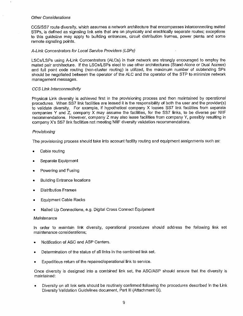
Other Considerations
CCSISS7 route diversity, which assumes a network architecture that encompasses interconnecting mated STPs, is defined as signaling link sets that are on physically and electrically separate routes; exceptions to this guideline may apply to building entrances, circuit distribution frames, power plants and some remote signaling points.
A-Link Concentrators for Local Service Providers (LSPs)
LSCslLSPs using A-Link Concentrators (ALCs) in their network are strongly encouraged to employ the mated pair architecture. If the LSCslLSPs elect to use other architectures (Stand-Alone or Dual Access) and full point code routing (non-cluster routing) is utilized, the maximum number of subtending SPs should be negotiated between the operator of the ALC and the operator of the STP to minimize network management messages.
CCS Link Interconnectivity
Physical Link diversity is achieved first in the provisioning process and then maintained by operational procedures. When SS7 link facilities are leased it is the responsibility of both the user and the provider(s) to validate diversity. For example, if hypothetical company X leases SS7 link facilities from separate companies Y and Z, company X may assume the facilities, for the SS7 links, to be diverse per NllF recommendations. However, company Z may also lease facilities from company Y, possibly resulting in company X's SS7 link facilities not meeting NllF diversity validation recommendations.
Pro visioning
The provisioning process should take into account facility routing and equipment assignments such as:
Cable routing
Separate Equipment
Powering and Fusing
Building Entrance locations
Distribution Frames
Equipment Cable Racks
Nailed Up Connections, e.g. Digital Cross Connect Equipment
Maintenance
In order to maintain link diversity, operational procedures should address the following link set maintenance considerations;
Notification of ASC and ASP Centers.
Determination of the status of all links in the combined link set.
Expeditious return of the repairedloperational link to service.
Once diversity is designed into a combined link set, the ASCIASP should ensure that the diversity is maintained:
Diversity on all link sets should be routinely confirmed following the procedures described in the Link Diversity Validation Guidelines document, Part Ill (Attachment G).

Whenever maintenance or circuit order activity occurs on a link, or a failed link is restored, diversity on the combined link set should be confirmed following the procedures described in the Link Diversity Validation Guidelines document, Part Ill (Attachment G).
At a minimum, validation of diversity on all interconnected links in all link sets should be performed at least once every six (6) months following the procedures described in the Link Diversity Validation Guidelines document, Part 111 (Attachment G).
G. Catastrophic SS7 Network Failures
Each ASPIASC is responsible for providing a point of contact. Contact numbers should be non toll free numbers and associated with the organization responsible for handling SS7 Catastrophic Network Failure reports. A contact list for SS7 Catastrophic failures is available in the NllF Company Specific Contact Directory.
3. LINK INSTALLATION
During the installation period, all inquiries will be referenced by the ASP Service Order number and circuit identification.
A. Signaling Point of lnterconnection (SPOI)
Signaling Point of lnterconnection is a physical location on 557 links, where the ASP and ASC exchange SS7 messages. The SPOI location may be provisioned at the POT for testing of links with a theoretical point of physical demarcation, be co-located with a POT, or remotely located from present POT locations. Diversity requirements for Signaling Links should be considered in developing SPOl locations.
6. Pre-service Testing
Each company is responsible for that portion of the overall SS7 link(s) circuit they are providing.
Each company must ensure that their link segments have been installed correctly, prior to cooperative acceptance testing.
C. Acceptance Tests For SS7 Link Circuits
Link circuits that are being installed, as a facility should first be tested at Level 1. The recommended tests for DS-1 acceptance testing is documented in, PART IX, Section 5F; Acceptance of DS-1.
When such testing meets the parameters for acceptance of the DS-1 facility, the recommended tests to ensure compatibility of the DS-1 to pass MTP Levels 2 & 3, is documented in, PART Ill, Attachment A; MTP Compatibility Tests, (Levels 2 $ 3)
D. ASP Prove In Period
A prove in period, not to exceed seven (7) days is recommended, subject to the bilateral agreement of the Service Providers. The 24 hour SP to SP Acceptance limits should not be exceeded in any 24 hour interval during the prove in period.
E. Synchronization
Improper synchronization can result in circuit impairments which should be investigated and synchronization problems corrected. Problems that cannot be resolved, should be referred to your Synchronization Coordinator. Companies' Synchronization Coordinators are listed in the NllF Company Specific Contact Directory, which is available from the NIIF.

If the ASCIASP has its own primary frequency standard that meets the CCITT standard for national networks (G.811, G.822), synchronization of the digital SS7 link(s) will be by the plesiochronous method of operation. If either network does not conform to the CCITT standard, the non-conforming company will use loop timing to accept SS7 link(s) timing from the conforming company. When the link interface is a DSOA interface, the interface must be plesiochronous or timed to the same source as the facility.
F. Compatibility Testing
SS7 Inter-Network Testing
SS7 Inter-Network trunk signalling testing is a pre-cutover requirement.
The following tests, MTP, ISUP and SCCP compatibility tests, are recommended to verify the compatibility of networks during interconnection. These tests are intended to be used as a recommended set of minimum tests of the SS7 protocol.
It is assumed that the two (2) interconnecting networks may have some additional tests they may wish to perform during interconnection. In this case, these tests should be part of the bilateral agreements developed for SS7 network interconnections.
Network compatibility testing verifies the correct interworking of two SS7 implementations. The tests are written for the interconnection of two given implementations.
The full test suite of all recommended tests should be run between the two interconnecting companies for any interconnection configuration that was not previously tested. Both the manufacturer model and software load of the interconnecting signaling network elements defines the interconnection configuration. Subsequent interconnections, using configurations previously tested by the two interconnecting companies, may be tested at their discretion.
The tests in this document have been divided into Intrusive Tests and Non-Intrusive Tests and defined as follows:
Intrusive Tests - The interconnecting circuit shall be interrupted, with the testing unit inserted into the circuit and acting as an emulator to the signaling point under test.
Non-Intrusive Tests - The test shall be able to observe traffic traversing the link(s) between the two (2) signaling points, in a monitor mode.
Message Transfer Part (MTP) Compatibility Tests - Part 111 (Attachment A)
The minimum set of MTP level 1,2, and 3, protocol compatibility tests are required for switches between interconnecting (ASPIASC) networks in support of SS7 link interconnection.
ISDN User Part (ISUP) Compatibility Tests - Part 111 (Attachment B)
The minimum set of ISUP protocol compatibility tests are required for switches between interconnecting (ASPIASC) networks implementing ISUP trunk interconnection.
Signaling Connection Control Part (SCCP) Compatibility Tests-Part Ill (Attachment C)
The minimum set of SCCP tests are required for switches between interconnecting (ASPIASC) networks implementing Toll Free Database and LlDB interconnecting services. Prior to the initiation of any testing, bilateral agreements will need to be reached defining entries to the Gateway screening, routing and global title tables required to support the testing.
G. Test Severity Analysis Criteria - Part Ill (Attachment D)

The Test Severity Analysis Criteria describes the potential impact of performing these compatibility tests on the network.
H. Completions
After performance of the link(s) circuit acceptance tests and alignment of the link(s) by the SS7 protocol, the control office should report the order as completed. The acceptance of Level 1, 2, 3 tests would constitute a link in service.
1. Rearrangements
The ASP or ASC will coordinate rearrangements not resulting in a change of operation or design. Removal from service, rearrangement timing and completion testing will be negotiated on an individual basis. Upon completion of the rearrangement, sufficient cooperative testing should be performed to ensure the proper operation of the service.
J. Timer Values
ASC and ASPS need to exchange T2 timer settings prior to interconnection.
4. LINK MAINTENANCE
The ASC is responsible for performing the necessary tests and performance monitoring to determine the nature of the SS7 link (s) trouble. Cooperative testing and Performance Monitoring may be required to identify troubles that are not associated with the physical circuit transport. If the trouble is found to be in the ASPIASC provided portion of the link (s), the ASPIASC will report the trouble to the appropriate ASPIASC control office or the designated trouble reporting office. These links are to be treated as Order Wires for restoration priority purposes. Restoration of these links is to be pre-planned, through bilateral agreements.
Routine Maintenance Activities
It is the recommendation of the NllF that all routine maintenance and scheduled work activities be performed during hours of minimum traffic (e.g., during an 11:OO pm to 500 am "maintenance window") so that any inadvertent failure impacts the least number of customers.
At a minimum, high risk, potentially service affecting maintenance and growth procedures should be scheduled during weekend and off-hours. The overall methods, procedures and scheduling of these work activities should be reviewed by a second tier maintenance organization.
The activities that may affect other network service providers must be coordinated, which includes both intra- and inter-carrier networks.
Non Scheduled Work Activity
If customer service is being impacted, the minimum work activity will occur to restore the system to a stable performance state. Complete system recovery activity will be scheduled for the next maintenance window period.
A. Trouble Reporting
The following types of information should be exchanged at the time of the trouble referral.
Circuit identification number [ASP circuit identification 41 Character Common Language (CLCI)] for circuit specific troubles.
Date and Time of referral

Nature of the trouble and any other information that may be of assistance in resolving the trouble.
The name or initials and telephone number of the person referring the trouble.
Trouble ticket number(s) or equivalent and the name or initials of the person accepting the trouble. Identify trouble report as a link. SS7 Link "Circuit Specific" troubles will be reported to the control office.
The ASCslASPs will provide specific contact numbers for the control offices or other designated report centers. This information is conveyed through the Ordering process.
SS7 Link "Non Circuit Specific" troubles (e-g. Data Base, Point Code) will be reported to the appropriate Network Service Center (NSC) or equivalent center.
The ASCsIASPs will provide a contact NSC or equivalent center number.
Sectionalization and Repair
While link facility sectionalization is the responsibility of the ASC, it could involve cooperative testing with the participation of both ASC and ASP.
The ASPIASC employees will limit their repair activities to their respective facilities andlor equipment.
C. Maintenance of SS7 Links Within a Higher Rate Facility
When a SS7 link fails because of a failure in higher rate facility e.g. DSI, DS3, etc., the ASP or ASC receiving the alarm should notify the other party of the expected impact on the SS7 interconnection. Maintenance of the higher rate facility will be in accordance with existing procedures.
D. Trouble Clearance
After a link trouble has been cleared the ASPIASC shall contact the other to advise that the trouble has been cleared, the nature of the trouble found and the action taken.
Trouble Repott Status
The Access Service CustomerIAccess Service Provider receiving the initial trouble referral shall provide a status on the disposition of that referral based on local agreements negotiated at the time of referral or requested on an individual case basis.
. Subsequent to the initial status report on the disposition of the trouble report periodic status's shall occur based on the following criteria: - When the trouble has been isolated - When there is a significant change in the status of the trouble. - The negotiated status interval has expired.
Where mechanized trouble notification is utilized the receiving company shall status their appropriate systems based on paragraphs A and B, in addition it shall be the responsibility of the company issuing the trouble report to poll the mechanized status system for the status of the trouble report.
Escalations if necessary shall be in accordance with identified procedures.
When a SS7 link(s) trouble has been cleared, the link(s) may or may not be automatically restored to service. If manual intervention is necessary on the part of the ASPIASC or both, it should be coordinated by both parties. Each party will verify that the affected link(s) have been restored and are carrying traffic. If the link(s) fail to align or to carry traffic, the parties will continue the maintenance effort until the problem is resolved.

When trouble reports are being closed out between an Access Service ProviderIAccess Service Customer, whether they are using a mechanized system or a verbal notification, the disposition should be furnished by the company clearing the trouble, and the following information shall be provided:
The ASC andlor ASP should agree to provide the following information when closing a mutual trouble report: Circuit IDItelephone number Trouble Report Number (ASCIASP number) Trouble Disposition (e.g., bad cable) Resolution details (e.g., cut to new cable) ASC will inform ASP if this trouble is measured. Referral time, returned time, No Access Time. If trouble report results in a service charge, the ASP will provide this info to the ASC
When there is a disagreement on the disposition, the parties engaged in the dispute shall document their respective positions, and the names of the individuals engaged in the dispute for audit purposes. Escalations if necessary shall be in accordance with identified procedures.
If after a trouble has been cleared and either the ASP or ASC wishes to change the Disposition, such changes shall be negotiated.
E. ASP Node To ASC Node Interconnect Testing And Analysis
The SS7 link(s) between an ASP and ASC are network to network interconnections. Trouble conditions may be experienced that cannot be resolved by each carrier testing and maintaining its own portion of the link(s). Some conditions may only be apparent to either the ASP or the ASC and require cooperative analysis of each others trouble indications or other data to sectionalize troubles. While it is the responsibility of the ASC to coordinate such activity, the ASP has the responsibility to notify the ASC of problems which may not be apparent to the ASC.
5. TRUNK RESPONSIBILITIES
A. Access Service Customer ASClASP
(See NllF Reference Document, Part 11, Installation and Maintenance Responsibilities Switched Access Services Feature Groups B, C, and D).
B. Conversion of Multi-frequency Trunks to SS7
Conversion from in-band signaling to SS7 cannot be accomplished without a thoroughly planned process. The ASPIASC implementation team should meet to discuss and identify all of the steps necessary for a successful trunk conversion. Each ASPIASC should establish a Cutover Committee consisting of permanent members from the Ordering, Provisioning, Engineering, Operations, SS7 Control Center and Billing disciplines. Account Representation for the ASC desiring interconnect may also be present when appropriate. The responsibility of the committee is to ensure a smooth conversion through scheduling and addressing, at a minimum, the concerns listed below. The following guidelines are offered as a starting point for discussion between an ASC and the ASP. They are not all inclusive.
TIME OF THE CONVERSION On what day will the actual conversion start? What time during the day will it take place? If it is out of hours, there may be expense related concerns of work force adjustments. Times may have to be correlated with traffic volumes dependent upon trunk capacity.
TRUNK OPERATIONS TEST Is this the first time a specific configuration (End Office Switch-Access Tandem-ASC Switch) has been tested? If so, a comprehensive test plan is suggested. If not, a substantially abbreviated test procedure may be appropriate. Will transmission test be performed?

TRANSITION TRUNK REQUIREMENTS Will a transition trunk group need to be built? It should also be determined how the trunks will be converted with minimal service interruption. One method is to create a new trunk group for the SS7 trunks and overflow the MF trunk group to the SS7 group (or vice versa). Converting in this manner allows all trunks to be in service with the exception of those which are actively in the conversion process.
MAXIMUM NUMBER OF TRUNKS FOR CONVERSION During that time that the trunks are actually being converted, they will be out of service. It must be determined how many trunks can be removed from service without adversely affecting traffic. Dependencies are the size of the trunk group, spare capacity and the time of conversion. Specific identification of trunks must be coordinate between the companies to ensure that both companies are converting the same trunks at the same time.
MANUAL VS AUTOMATIC Will the ASPIASC be using a mechanized procedure for converting the trunks? This information may be useful in scheduling the work.
FACILITIES CHANGES It is not anticipated that there will be facility changes associated with the conversion of trunks. If they are required, the information should be conveyed at the preconversion meeting.
EQUIPMENT CHANGES Most trunk equipment used for in band signaling should also work with SS7. However, some manufacturers may have designed iheir trunk equipment to work properly in the off-hook state only. This equipment, when used for SS7, would provide degraded transmission since, in relation to E&M signaling, the circuit will always be on-hook.
SWITCH TYPES The switch types involved in the conversion should be identified to address special needs of specific switches. For example, a switch may require that the Trunk Circuit ldentification Code (TCIC) and the trunk number be of the same value. Identification of the switches will also allow the companies to determine the extent of testing that will take place (see TRUNK OPERATIONS TEST above).
NMC NOTIFICATION The NMC should be notified of the conversion to enable the center to monitor the trunk group, especially during the time of conversionlreduced capacity. The NMC may also be able to inform the Conversion Team of any special calling events (mass calling) which may be occurring at the time of the conversion.
SCHEDULE As offices become equipped for Common Control Switching Access Capability (CCSAC), it is likely that more than one ASC will want to interconnect with a specific end office. The scheduling of conversions must be coordinated by the ASP, with individual ASCs, and agreed to by the involved companies.
TIMER VALUES The ASC and ASP switches and STPs have many timers associated with link operation and call setup. Since only parameters and not the actual values are stated in technical references, it is likely that the ASC and the ASP will have different time settings for the same timer. Although there is no requirement that the value of specific timers be the same (see note) in both companies, the sharing of the values will provide each company with additional information for trouble resolution.
Note: The T2 Link Timer is the only known exception and must have different values at each end.
To ensure network integrity and reliability, SS7 Timer settings (MTP Level 2 and Level 3, ISUP and SCCP) should be exchanged at time of interconnection negotiation.
POINT CODES If an ASCIASP is contemplating interconnecting, it is essential that point code range information be known well in advance to enable the control center to update the STP during the scheduled split mode operation. Point codes include those of the STP, the interconnecting switches and any alias point codes.

RCT (Route-Set-Congestion Test) METHODOLOGIES It is recommended by the NllF that interconnected networks adopt the practice of responding to TFC (Transfer Controlled) messages by assigning RCT (Route-Set-Congestion test) messages using SLS (Signaling Link Selection) codes that ensure an equal distribution on all the links in the linkset (combined). Prior to CCS interconnection the interconnecting companies should exchange RCT methodologies.
TRUNK CONFIGURATION Using In Band signaling, it is possible for an ASC to have one large trunk group from the ASP to the POP and then split the facilities to several different switches on their side of the POP. In this arrangement, the ASP routes all traffic to the single trunk group and the ASC splits it according to their needs. This same configuration will not work using SS7 unless the trunk group is split on the ASP side of the POP as well. It is necessary to split the trunk group because in the SS7 environment, traffic is routed between switches and not between a POP and a switch. One method of accommodating an ASC with this situation, would be to split the trunk groups between switches and then first route all traffic to one of the groups. That trunk group could then route advance to another. The ASC would be able to balance loads between switches through proper sizing of the trunk groups. At the conversion meeting it should be determined if this situation exists and if it does, how it will be handled. How will traffic be routed to the separate trunk groups? What are the switched nomenclature? Will the trunk groups have to be resizedlrearranged? Will the trunk groups be rearranged, prior to SS7 conversion?
As a result of technological changes in the network due to the implementation of SS7 there has been an increase in short duration calling patterns (Abandoned Calls) in an lnterworking environment. Therefore it is the recommendation ofthe NllF that the following actions take place where interworking is encountered between interconnected carriers. Where appropriate to reconcile the situation:
All Service Providers having switches with:
TCRA Timer should be in compliance with ANSI (TI .I 13 Issue 3) which recommends a setting of twenty (20) seconds.
Inter Stage Timer (IST)* should be set at fifteen (1 5) seconds.
Partial Signal Partial Dial (PSPD) Timer should be set at a minimum of twenty (20) seconds and at a maximum of thirty (30) seconds.
FREQUENCY OF CONTINUITY TESTS When In Band signaling is used, continuity of the trunk selected is assured by call setup. Continuity testing is also available on SS7 trunks. The switch will automatically send, receive and measure tones placed on the trunk prior to setting up a call. The switch will perform continuity on a circuit at a variable rate of 1 out of n times where n has a value of 1 to 16. It is this information (the value of n) which should be exchanged with the ASC. The NllF has agreed to perform continuity operation tests, at a minimum rate of ( I ) one out of (8) eight.
NOTE: Where technology does not exist to facilitate meeting the above criteria, local negotiations should take place.
2-WIRE CONTINUITY CHECK EMULATION ON A 4-WIRE SWITCH An exchange terminating a 4-wire circuit is recommended to provide an additional procedure using two tone continuity check procedures. Optionally, by agreement between connecting 4-wire exchanges, either:
Both exchanges emulate 2-wire exchanges in the continuity check procedure of Section 8.2 (Continuity-check for 2-wire speech circuits) of T1 .1 13.4. Note, this requires an equipment upgrade of both exchanges to detect 1780 Hz tone. One of the exchanges terminating a 4-wire circuit may emulate operation of a 2-wire exchange in the continuity check procedure in Section B.3 (continuity-check between a 2-wire and 4-wire exchange) of T1 .I 13.4, while the far end exchange must furnish 4-wire to 2-wire procedure. Note, in this case, only one exchange requires an equipment upgrade, however, there is increased administration requirement to ensure correct 4-wirel2-wire configuration.

The use of two tone continuity check procedures will allow detection of inadvertent loops in the trunk facility between exchanges that terminate 4-wire circuits because different frequencies are transmitted and received.
DIVERSITY ARRANGEMENTS The ASPIASC should exchange link diversity arrangements (Planned and Current).
NEW PARAMETERS Companies who have completed SS7 interconnection and acquire customers with ISDN capabilities have a need and responsibility to communicate to their interconnected network providers the passage of such parameters.
3.1 KHz audio and speech should be passed by all interconnecting SS7 partners. Where known non- conformance~ exist, dialogue needs to take place.
Per local negotiations, all interconnecting companies utilizing ACC should acknowledge and respond when an ACC message is received.
Interconnecting parties should exchange the initial value of the Hop Counter at the time of negotiation for interconnection and as changes are anticipatedlmade in signaling between the two networks. The recommended initial value of the Hop Counter as determined by the NllF is 17.
EMERGENCY COMMUNICATIONS In the remote event that a total SS7 failure is experienced, some means of communication between personnel in interconnecting networks, may be required. The ASPIASC should determine what emergency communications are already available andlor what alternative methods, if any, will be provided.
It is recommended that all interconnecting networks (ICNs) and manufacturers interconnect via Public Packet Switched Network (PPSN), non PSN Access, as part of a Closed User Group, in support of and to provide backup of the voice emergency communications network. The PPSN is to be utilized as a backup to the PSN as part of the Emergency Communications System (ECS). Information to be communicated between entities should be identified and shared for ECS information. The following information was developed by the NllF and should be utilized, where possible: - Security Password: (Exchangeable) - Station Handshake: (ASCII Text) - To: (Addressee) - From: (Company who sent message) - Date: (Current Date) - Time: (Current Time) - Outage Date: (Outage Date) - Outage Time: (Outage Time) - Node Type: (STP,SCP,Etc.) - Location: (Office where incident occurred) - Point Code: (Point Code of Office) - Severity: (Isolation, Critical, Major, Minor, etc.) - Vendor: - Comments (if any) - End of Comments - END: (Identifies End of Message)
LINK RESTORAL OBJECTIVE
AVAILABLE OPTIONAL AUTOMATIC TESTING
Signaling Link Test Message (SLTM). Automatically run during link alignment. Not necessary for trunk conversion.
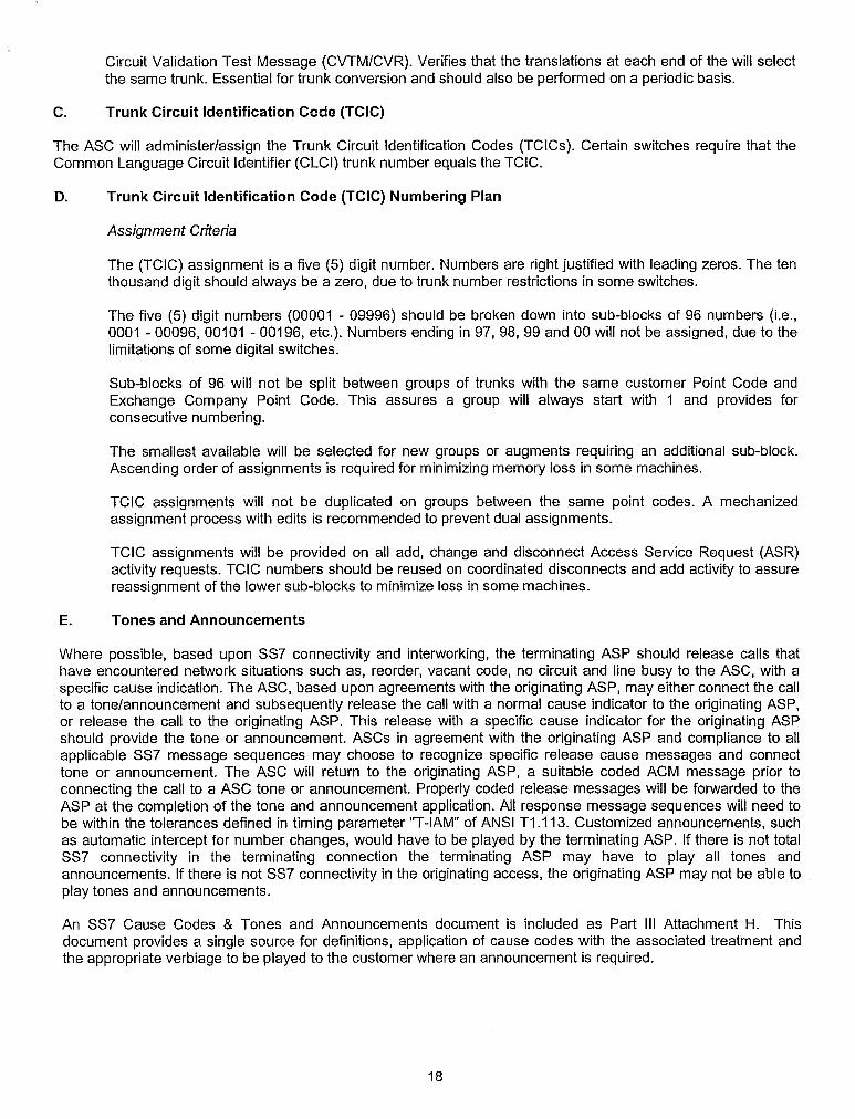
Circuit Validation Test Message (CVTMICVR). Verifies that the translations at each end of the will select the same trunk. Essential for trunk conversion and should also be performed on a periodic basis.
C. Trunk Circuit ldentification Code (TCIC)
The ASC will administerlassign the Trunk Circuit ldentification Codes (TCICs). Certain switches require that the Common Language Circuit Identifier (CLCI) trunk number equals the TCIC.
D. Trunk Circuit ldentification Code (TCIC) Numbering Plan
Assignment Criteria
The (TCIC) assignment is a five (5) digit number. Numbers are right justified with leading zeros. The ten thousand digit should always be a zero, due to trunk number restrictions in some switches.
The five (5) digit numbers (00001 - 09996) should be broken down into sub-blocks of 96 numbers (i.e., 0001 - 00096, 00101 - 001 96, etc.). Numbers ending in 97, 98, 99 and 00 will not be assigned, due to the limitations of some digital switches.
Sub-blocks of 96 will not be split between groups of trunks with the same customer Point Code and Exchange Company Point Code. This assures a group will always start with 1 and provides for consecutive numbering.
The smallest available will be selected for new groups or augments requiring an additional sub-block. Ascending order of assignments is required for minimizing memory loss in some machines.
TCIC assignments will not be duplicated on groups between the same point codes. A mechanized assignment process with edits is recommended to prevent dual assignments.
TCIC assignments will be provided on all add, change and disconnect Access Service Request (ASR) activity requests. TCIC numbers should be reused on coordinated disconnects and add activity to assure reassignment of the lower sub-blocks to minimize loss in some machines.
E. Tones and Announcements
Where possible, based upon SS7 connectivity and interworking, the terminating ASP should release calls that have encountered network situations such as, reorder, vacant code, no circuit and line busy to the ASC, with a specific cause indication. The ASC, based upon agreements with the originating ASP, may either connect the call to a tonelannouncement and subsequently release the call with a normal cause indicator to the originating ASP, or release the call to the originating ASP. This release with a specific cause indicator for the originating ASP should provide the tone or announcement. ASCs in agreement with the originating ASP and compliance to all applicable SS7 message sequences may choose to recognize specific release cause messages and connect tone or announcement. The ASC will return to the originating ASP, a suitable coded ACM message prior to connecting the call to a ASC tone or announcement. Properly coded release messages will be forwarded to the ASP at the completion of the tone and announcement application. All response message sequences will need to be within the tolerances defined in timing parameter "T-IAM" of ANSI T I .I 13. Customized announcements, such as automatic intercept for number changes, would have to be played by the terminating ASP. If there is not total SS7 connectivity in the terminating connection the terminating ASP may have to play all tones and announcements. If there is not SS7 connectivity in the originating access, the originating ASP may not be able to play tones and announcements.
An SS7 Cause Codes & Tones and Announcements document is included as Part Ill Attachment H. This document provides a single source for definitions, application of cause codes with the associated treatment and the appropriate verbiage to be played to the customer where an announcement is required.

F. Trouble Report Disposition
When trouble reports are being closed out between an Access Service ProviderlAccess Service Customer, whether they are using a mechanized system or a verbal notification, the disposition should be furnished by the company clearing the trouble, and the following information shall be provided:
The ASClASP should agree to provide the following information when closing a mutual trouble report: Circuit IDItelephone number Trouble Ticket Number (ASCIASP number) Trouble Disposition (e.g., bad cable) Resolution details (e.g., cut to new cable) ASC will inform ASP if this trouble is measured. Referral time, returned time, No Access Time. If trouble ticket results in a service charge, the ASP will provide this info to the ASC
When there is a disagreement on the disposition, the parties engaged in the dispute shall document their respective positions, and the names of the individuals engaged in the dispute for audit purposes. Escalations if necessary shall be in accordance with identified procedures.
If after a trouble has been cleared and either the ASP or ASC wishes to change the disposition, such changes shall be negotiated.
6. TRUNK INSTALLATION
A. Point of Presence (POP) Serving Multiple Switches
Where an Access Service Customer (ASC) has multiple switches served by one POP, a separate trunk group for each switch must be established from the ASP switch to the POP to accommodate SS7 trunk traffic. Each trunk group will require the unique Signaling Point Code (SPC) for each ASC switch and ASP switch. When an ASC has multiple switches connecting through a single POP or a single switch connecting to multiple POPS, separate trunk groups must be established using the unique Signaling Point Code of each ASC switch and ASP switch.
7. TRUNK TROUBLE DETECTION RESPONSIBILITIES
It is recommended that continuity checks (COT) be performed by ASPS and ASCs on a one (1) out of eight (8) statistical basis. Because of different manufactures implementation of COT capabilities, this may have to be pelformed at either the trunk group level, or at the office level. If the COT must be performed at the trunk group level, then the one (1) out of eight (8) COT will only be performed on all access trunk groups. If the COT is designated at the office level, then the one (1) out of eight (8) requirement is performed on the entire office base. Between 4-wire switching offices, COT is performed on a loop basis, however, when one or both offices involved are 2-wire switches, each transmission direction is checked independently. As long as the continuity check is performed at recommended levels, a "killer" trunk condition should only occur if the trunk is looped.
NOTE: Where technology does not exist to facilitate meeting the above criteria, local negotiations should take place.
8. SCREENING AND TRANSLATIONS
A. Final Global Title Translations (FGTT)
Final Global Title Translations (FGTT) should be performed in the terminating network. Interconnecting parties should discuss their routing and Gateway Screening of Network Management Messages between interconnected STPs to ensure that all appropriate messages can be routed in the presence of route failures.

In order to interconnect to a network which utilizes cluster routing, the NllF recommends that each network demonstrate that network management features are being provided to the other network, and conform to the following interworking rules:
o The interconnecting network should not ignore TFP, TFR, TFA,TCP, TCR, TCA, and signaling route set test messages, and shall respond, andlor send the appropriate RSxIRCx message if the above TFPITFR, TCPITCR messages received are in conformance with ANSl Standards.
Network elements performing cluster routing in receipt of a network management message should create and maintain a status listing of all members within the defined cluster to which it performs routing until appropriate allow messages have been associated with all such members.
When the TFC message is sent, the message shall contain the full Point Code (PC) of the message Point Code of the Message Destination (DPC) and the affected Point Code (the route to which is in congestion).
In the event of routing methodology changes the interconnected network should be notified by the company initiating the change, before implementing cluster routing.
Member 000 should never be assigned for a cluster used for an End Officerrandem ISCP point code, i.e. point codes of a signaling end point. The cluster member code 000 is reserved for addressing signaling points that serve as a signaling transfer point.
When performing any live network testing, a non working cluster should be used to avoid network incidents due to misinterpretations of signaling protocols.
NOTE: Where technology does not exist to facilitate meeting the above criteria, local negotiations should take place.
B. Translation Types
A uniform applicationlutilization of a numbering scheme will prolong the life of the resource.
The ANSl Standard (TI .I 12.3-1996, Annex A) specifies standard Translation Types (TTs) which should be used. The standard also specifies multiple translation types (TTs ) for two applications (CLASS and LIDB) TTs 251 or 6; 253 or 2 should be used in accordance with the standard. The following recommendations be considered when interconnecting TTs 251 or 6; 253 or 2 with another Service Provider:
a Translation Types being utilized by the ILEC should be considered for adoption by the newly established CLECs during local negotiations.
In the event that translation types are already being used by the interconnecting CLEC that differ from the ILEC then the parties involved should engage in local negotiations to determine their numbering convention.
In the event that a CLEC is interconnecting with multiple ILECs then the involved parties shall engage in local negotiations.
a Existing service ProvidersICustomers already utilizing specific Translation Types shall engage in local negotiations to determine what Translation Types should be utilized.
Where existing service providerslservice companies are already interconnected and are now proposing to provide services new to the area, then local negotiations should take place to determine the Translation Type (TT) to be used.
C. TCAP Transaction Looping
TCAP transaction looping can congest B links very quickly. Several mechanisms are available (TlS1.6) to prevent such looping and should be implemented through bi-lateral agreements. Two mechanisms, Gateway

Screening and Translation-Type mapping loop-prevention, were proven through industry (NTC Phase 10) testing to prevent looping caused by incoming messages.
The NllF recommends the following:
For TCAP transactions, interconnected companies should utilize loop detectionlprevention mechanisms bi-laterally.
Reference: TISI .6 - Technical Requirements for Number Portability - Database and Global Title Translations. (TlS1198- 1 74)
9. Rules for Populating JIP
1. JIP should be populated in the lAMs of all wireline and wireless originating calls where technically feasible.
2. JIP should be populated with an NPA-NXX that is assigned in the LERG to the originating switch or MSC.
3. The NllF does not recommend proposing that the JIP parameter be mandatory since calls missing any mandatory parameter will be aborted. However, the NllF strongly recommends that the JIP be populated on all calls where technologically possible.
4. Where technically feasible if the originating switch or MSC serves multiple stateslLATAs, then the switch should support multiple JlPs such that the JIP used for a given call can be populated with an NPA-NXX that is specific to both the switch as well as the state and LATA of the caller.
If the JIP cannot be populated at the state and LATA level, the JIP should be populated with an NPA- NXX specific to the originating switch or MSC where it is technically feasible.
5. Where the originating switch cannot signal JIP it is desirable that the subsequent switch in the call path populate the JIP using a data fill default associated with the incoming route. The value of the data fill item is an NPA-NXX associated with the originating switch or MSC and reflects its location.
6. When call forwarding occurs, the forwarded from DN (Directory Number) field will be populated, the JIP will be changed to a JIP associated with the forwarded from DN and the new called DN will be inserted in the IAM.
7. As per T I .TRQ2, the JIP should be reset when a new billable call leg is created.
10. SS7 NETWORK SECURITY BASE GUIDELINES
This section specifies the minimum set of security features to be adopted by Access Service Providers and the Access Service Customers and is documented in Part Ill Attachment I.
SS7 network providers are responsible for ensuring the reliability and security of their own SS7 networks with respect to defending against the propagation of abnormal SS7 signaling messages when interconnected with other networks. This responsibility should ensure protection against unexpected SS7 messages, SS7 messages with protocol errors, attempts at sabotage, or any other harmful conditions that may be propagated across interconnected SS7 networks.
It should be noted that SS7 network intermediate nodes generally examine those parts of incoming messages with respect to routing of the message. The SS7 destination node examines additional information for the proper processing of the message, and this may include additional security considerations. Examination of the content of every message routinely is not done, and may not be practical. Various methods of protocol analyzation that

further examine message content are available to detect and resolve troubles, but are generally utilized only on an exception basis.
A variety of processes and responsibilities intended to ensure reliability, network security, and risk minimization associated with SS7 network interconnection are outlined elsewhere in the document.
I 1. SS7 SOFTWARE VALIDATION
Service providers and vendor/manufacturers have an obligation to their customers to provide the highest standard of error free software possible. In light of this obligation the industry has developed a set of recommendations for the validation of software and is documented in Part Ill Attachment J.
12. DUAL STP FAILURE PREVENTION PROCEDURES
The NllF recommends that each STP OwnerIOperator have in place a written procedure to assist in the prevention of dual STP failure. Part Ill Attachment K provides a minimum set of recommended guidelines to prevent dual STP failures.
13. COMBINED NODE - MINIMUM SET OF GUIDELINES
A. Architecture
Typical Combined Node Architectures are identified in the following two network diagrams:
Network "C"
Switch
Combined Node Interconnection Architecture #1
Voice Trunks Network "D"
Switch
Voice Trunks
Figure 3 - Combined Node Interconnection Architecture #I

Network "C"
Switch
Combined Node Interconnectii
Voice Trunks Network “D"
Combined Node Interconnection Architecture #2
Voice Trunks Network “D"
C Combined Node STPISwitch
Voice Trunks
Figure 4 - Combined Node Interconnection Architecture #2
B. Routing And Configuration
Load Balancing of the interconnecting Links (A, BID) is required as specified in Load Balance Tests in the NllF SS7 Reference Document -Part Ill (Attachment A - Test 1.27).
It is the responsibility of each network operator to send balanced traffic. In situations where special translations and screening are required to achieve load balancing on traffic originating from the combined node, those translations are the responsibility of the combined node ownerloperator.
C. Network Management
Where Combined Nodes are utilized in an interconnected environment, the interconnected parties need to identify and resolve operational concerns (e.g., Load Balance)
It is preferred that a single point code be established for the switch portion of the combined node, and a different point code be established for the STP portion of that switch.
Functionality of the combined node must send and respond to Network Management Messages (TFPiTFCRFRIetc.) in accordance with established NllF Procedures as found in the NIIF Reference Document (Part 111 - Section 8. Screening and Translations)
D. Diversity
The node should meet the established NllF Link Diversity guidelines. (Part Ill - Section 2 - Subsection E - Diversity)
E. Testing
When interconnecting with a Combined Node, all applicable tests are referenced in the NllF Reference Document - Part Ill -Attachments A, B, C, D, E, and F should be performed.

AFFIDAVIT OF SERVICE BY MAIL
STATE OF MINNESOTA ) ss.
COUNTY OF HENNEPIN Court File No. 04-3014
OWJA q?hg7i , being s t duly sworn, deposes and states that on the 5% day o /do/e/n,& ,2005, she served the attached AFFIDAVIT OF JEFF HARMON upon:
Dada Pollrnan Rogers Rolayne Ailts Wiest Ritter, Rogers, Wattier & Brown, LLP South Dakota Public Utilities Commission 3 19 South Coteau Street 500 East Capitol P.O. Box 280 Pierre, South Dakota 57504-5070 Pierre, South Dakota 57501-0280
(which is the last !mown address of said attorney) by depositing a true and correct copy thereof in the United States mail, postage prepaid.
Subscribed and sworn to before me this \ s w a y of -,* + ,2005.
Notary Public