united states army aviation planning manual84).pdf · * fm 101-20 field manual no. 6101-20;...
TRANSCRIPT

/ ¿^y /] y -, i 2
í--opy §
& Psr DA PM101-20
\ «
FIELD MANUAL
UNITED STATES ARMY
AVIATION PLANNING
MANUAL
y -.m l^iynV. 20310-°°^
\ivíj^^ino
\ \
»I HEADQUARTERS, DEPARTMENT OF THE ARMY
6 JANUARY 1984 Jm lASlsf'peÍJ^! ^ashihgion, D.C. 203^0
\

I
I
t
AUTHOR
f/VJ Uöl'Ztj !2fiS>c-jr9 %í ■"“ C^/o?
K1MRMK X;
\M
u
y

*e*CWDED par
m DA /
\ FM 101-20
FOREWORD
This manual is published in accordance with the provisions of AR OS-TO^and contains official U.S. Army aviation factors datàxin a single-source docu- ment to be used as a planning guide ONLY. The. factors, when used with otlrer Army prográm documents (e.g., Army Materiel Plan and Materiel Annex Part II to 5 Year Force! Structure), will assist commanders, planners, and programmers in estasblishing a basis for operational,^logistical, materiel, personnel, estimates, and thevcost re- quirements for combat readiness of all types and ^ models of Army aircraft. In the event such Army program documents, as mentioned above, indicate later revision, such revisions will take precedence.^ The data may be used in the preparation ofJ-A\ estimates by major commands (theater, field army, or equivalent) but will not be used as a basis of reporting cost or other data.
These planning factors were developed from diversified operational and logistical statistical data and were obtained from various Department of the Army staff offices and other Army agencies;
having primary responsibilities for the specific mission activities or related functions.
This manual is published in looseleaf form to facilitate insertion of revisions, changes, and/or additions. Each set of published planning factors will be revised on an 18-month cycle to ensure cur- rent and accurate data, as well as provide addi- tional factors of interest. TSARCOM is responsi-
ble for coordinating pertinent planning factors with the appropriate Army staff agency.
Users of this manual are encouraged to submit recommended changes or comments to improve the manual. Comments must be submitted on DA Form 2028, Recommended Changes to Publica- tions and Blank Forms. Reasons should be provid- ed for each comment to ensure understanding and full evaluation. Comments should be forwarded directly to Commander, U.S. Army Troop Support and Aviation Materiel Readiness Command, Directorate for Plans and Systems Analysis, ATTN: DRSTS-B, 4300 Goodfellow Boulevard, St. Louis, MO 63120.
Distribution of this Department of the Army publication to Active Army, National Guard, and United States Army Reserve units is by formula distribution and pinpoint distribution methods. Other DOD agencies should request copies re- quired from the Adjutant General, Washington, D.C. Under provisions of Army Regulation 310-1, Military Publications, normal publications supply channels should.be followed:
\
Requests from agencies outside of DOD will be forwarded to The Adjutant General, Washington, D.C.20315. <
Abbreviations used in this manual are listed in AR 310-50 (Standard abbreviations) or Military Standard 12C (Non standard abbreviations).
iJantar,on Library (ANR-PL) am Milit’-ï Documents Section 'Room l«18'Pr
snS-6O50 Washington. DC zQoiU
i/(ii blank)

F
L.

* FM 101-20
FIELD MANUAL
NO. 101-20
;
HEADQUARTERS DEPARTMENT OF THE ARMY
WASHINGTON, D. CM 6 January 1984
UNITED STATES ARMY “
AVIATION PLANNING MANUAL
Table of Contents
Forward Designation of Army Aircraft. Aircraft Type Classification....
Chapter 1. Section I.
II. III.
IV
OPERATIONS Aircraft authorization Flying hour program Replacement/Crash Damage Factors (Attrition) Standard aircraft characteristics
I
Chater 2. Section I.
II. III. IV. V.
VI. VII.
VIII. IX.
LOGISTICS AND MATERIEL Maximum allowable operating time (MAOT) (major components) Aircraft equipment Ferrying and shipping Tools Inspections Fuel and oil Maintenance man-hours Maintenance categories Survival Equipment
Chapter 3. PERSONNEL REQUIREMENTS Section I. Officer/warrant officer aviation personnel requirements
II. Enlisted aviation maintenance personnel requirements...
Chapter 4. Section I.
II. III. IV.
COSTS Army aircraft unit prices Aircraft unit flying hour costs Avionics cost Armament cost
Chapter 5. RESEARCH AND DEVELOPMENT OF MATERIEL
Page i iv viii
1-1 1-12 1-14 1-15
2-1 2-1 2-230 2-237 2-244 2-246 2-250 2-258 2-259
3-1 3-2
4-1 4-3 4-3 4- 3
5- 1
APPENDIX A REFERENCES
INDEX
This manual supersedes FM 101-20,15 August 1981. Library (ANR-PL)
ATTN: Military Documents Section Room 1A518, Pentagon Washington, DC 20310-6050
A-l
Index-1
L m

r
à

DESIGNATION OF ARMY AIRCRAFT (ROTARY WING) =
PRE-^ . •' • FERREO
POPULAR NAME AND TYPE
COMBAT ACCEPT SUBST
FOLLOW-ON -, AIRCRAFT v
COBRA
AH-lG TH-1G
ATTACK HELICOPTER
UH IB UH 1C UH-1M
AH-64A
CHINOOK
CH-47A/B/C
o>
CARGO TRANSPORT HELICOPTER -
YCH-47D
TARHE
CH-54A/B
CARGO TRANSPORT HELICOPTER
CAYUSE
OH-6A
OH-58A/C
KIOWA
ao
LIGHT OBSERVATION HELICOPTER
OH-58D
IROQUOIS
UH-1H
UH-1V
UTILITY HELICOPTER
OSAGE
TH 55A
TRAINER HELICOPTER
UH-60A LHX "
OFF THE SHELF
AV 010094

í

FM 101-20
DESIGNATION OF ARMY ARICRAFT (ROTARY WING) CONT’D.
PRE- FERRED
POPULAR NAME ANDTYPE
‘ ' COMBAT' ACCEPT
- SUBST .
FOLLOW-ON AIRCRAFT
BLACK HAWK
UH-60A
53 UH-1H
UTILITY HELICOPTER
APACHE
AH-64A ^-uig-a
ATTACK HELICOPTER
IROQUOIS
UH-1C/M oo UH-60A
UTILITY HELICOPTER
COBRA
AH-1S T
UH-1B UH-1C UH-1M
AH-64A
ATTACK HELICOPTER
IROQUOIS
EH-1
SPECIAL MISSION
HELICOPTER
EH-60A
v

1

FM 101-20
DESIGNATION OF ARMY AIRCRAFT (FIXED WING) (Cont.)
PRE POPULAR NAME FERREO AND TYPE
COMBAT ACCEPT SUBST.
FOLLOW-ON AIRCRAFT
U-8F
ÜÍMINOI L
oca
UTIl ITY AIRPl ANC
COURIER
U 10A
UTILITY AIRPLANE
U-21A/G RU-21A D/H
UTE
UTILITY AIRPLANE
MOHAWK
OV-1B/C/D RV-1D
OBSERVATION/SURVEIL- LANCE AIRPLANE
MESCALERO
T41B OFF THE SHELF
TRAINER AIRPLANE
COCHISE
T42A OFF-THE-SHELF
TRAINER AIRPLANE
AV 010095

'1
4P
%

V
FM 101-20
DESIGNATION OF ARMY AIRCRAFT (FIXED WING) CONT’D.
PRE- FERRED
POPULAR NAME ANDTYPE
COMBAT ACCEPT SUBST
FOLLOW-ON AIRCRAFT
AERO COMMANDER
U-9C =4 U-21A
UTILITY AIRCRAFT
C-12A/C RU-21J
HURON UTE
C-12D
CARGO AIRCRAFT
UV-18A
TWIN OTTER YVM'l i I L_n r—.
^-4 UTILITY STOL AIRCRAFT
U-1A
OTTER
UTILITY AIRCRAFT
U-21A
U-21F RU-21B.C
UTE
UTILITY AIRCRAFT
Source: TSARCOM-DRSTS-MT
vii

1
FM 101-20
Army Aircraft Type Claseifícation/Reclaasiftcatíon (TC/R) Schedule (Rotary Wing)
Type, Model Series (TMS)
Current Type
TCC-LCC Proposed TCC-LCC
FY-QTR of Actual/
Proposed TCC-LCC Replacement
System
Rotary Wing AH-1G (TH-lG) AH-1S AH-64A CH-47A CH-47B CH-47C CH-47D CH-54A CH-54B EH-1H EH-1X EH-60A OH-6A OH-58A OH-58C OH-58D TH-lG TH-55A UH-1B UH-lC UH-1H UH-1M UH-1V UH-60A
S-A S-A S-A S-B S-B S-A S-A S-B S-B L-(U) S-A S-A S-A S-A S-A
D S-A S-A S-B S-B S-A S-B S-A S-A
C-S
C-S C-S C-S
C-S C-S S-B
C-S C-S
S-A
C-S C-S
C-S C-S
88-1 77- 1 82-1 81-3 83- 1 84- 3 80- 4 88-4 90-4 79-3 78- 1 79- 2 86-4 86-4 81- 4 85- 3 72-1 84-4 80- 4 69-3 82- 4 83- 4 78-2 77-2
AH-lS AH-64A
CH-47D CH-47D CH-47D
OH-58C OH-58D
UH-60A UH-60A
UH-60A UH-60A
viii

V
FM 101-20
Army Aircraft Type Ciassifícation/Reclassifícation (TC/R) Schedule (Fixed Wing)
Type, Model Series (TMS)
Current TCC-LCC
Proposed TCC-LCC
FY-QTR of Actual/
Proposed TCC-LCC Replacement
System
Fixed Wing C-12A C-12C C-12D OV-1B OV-1C OV-1D RC-12D RU-21A RU-21B RU-21C RU-21D RU-21H RU-21J RV-1D
T-41B T-42A U-1A U-3A/B U8F U-9C U-10A U-21A U-21F
U-21G UV-18A
S-A S-A S-A S-B S-A S-A
D S-B S-B S-B S-B S-A
D S-A S-B S-A C-F
EXEMPT SB C-S S-B S-A S-A S-A S-A
C-S C-S C-S
0-0
C-S C-S 0-0
0-0 0-0 C-S C-S C-S C-S
76- 4 81-4 81-4 81-4 81-4 90- 4
77- 1 77-1 77- 1 80- 4 81- 1
78- 4 86-2 85-1 78-4 73-2 80-4 78-4 83-4 88-3 92-1 91- 4 77-1
OV-1D OV-1D
U-21A
U-21A
Source: AVRADCOM-DRDAV-ERT
IX
1
FM 101-20
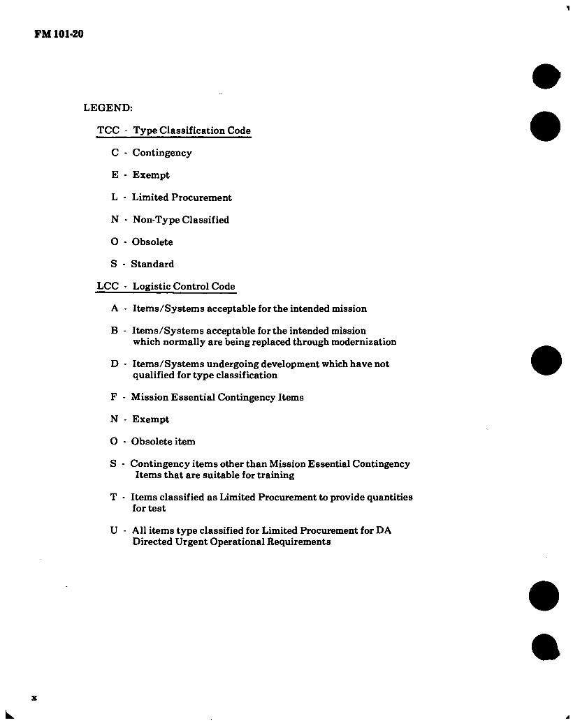
LEGEND:
TCC - Type Classification Code
C - Contingency
E - Exempt
L • Limited Procurement
N - Non-Type Classified
O - Obsolete
S - Standard
LCC - Logistic Control Code
A - Items/Systems acceptable for the intended mission
B - Items/Systems acceptable for the intended mission which normally are being replaced through modernization
D - Items/Systems undergoing development which have not qualified for type classification
F - Mission Essential Contingency Items
N - Exempt
O - Obsolete item
S - Contingency items other than Mission Essential Contingency Items that are suitable for training
T • Items classified as Limited Procurement to provide quantities for test
U - All items type classified for Limited Procurement for DA Directed Urgent Operational Requirements
x
L

FM 101-20
CHAPTER 1
OPERATIONS
Section I AIRCRAFT AUTHORIZATIONS
Aircraft authorizations are listed by TOE unit authorizations. The current Major Item Analysis (Data Sheets) contains details concerning
authorizations for specific areas or commands. The Basis of Issue (BOI) authorizations are up- dated to comply with the ARCSAIII evaluation.
1-1
Â

r
i
to 1-1. Basis of Issue — Aircraft Authorization Per Unit.
UNIT TOE TOTAL ACFT LOH AH-1 UH-1 UH-60 CH-47 CH-54 OV-1 U-21 NOTE
ARMORED DIV CBT AVN BN ATK HEL CO (2) CBT SPT AVN CO AVN CO
TRANS ACFT MAINT CO ARMD CAV SQDN
AIR CAV TRP CEWI BN HQ/HQ & OP CO
RECAP RECAP
RECAP
RECAP
17 17-85 17-387 57-57 17-87 55-427
17-105 17-108 34-165 34-166
164
135 72
15 46
2 26 26 3 3
66 56 24
32
10 10
51 42 42
9 9
22 22 6
14 2
25 15
15
3 3
C C
INFANTRY DIV (MECH) CBT AVN BN
ATK HEL CO (2) CBT SPT AVN CO AVN CO TRANS ACFT MAINT CO
ARMD CAV SQDN AIR CAV TRP
CEWI BN HQ/HQ & OP CO
RECAP RECAP
RECAP
RECAP
37 17-85
17-387 57-57 17-87 55-427 17-105 17-108 34-165 34-166
164 135 72 15 46
2 26 26 3 3
66 56
24
32
10 10
51 42
42
9 9
22 22
14 2
25 15
15
3 3
C C
INFANTRY DIV CBT AVN BN CBT SPT AVN CO (2) AVN GEN SPT CO ATK HEL CO TRANS ACFT MAINT CO
RECAP RECAP
7 57-55 57-57 57-58 17-387 55-427
199 114 30 46 36
2
74 44
32 12
48 21
21
44 19
14 3 2
33 30 30
FM
101-20

1-1. Basis of Issue — Aircraft Authorization Per Unit (Con’t).
UNIT
TOTAL
TOE ACFT LOH AH-1 UH-1 UH-60 CH-47 CH-54 OV-1 U-21 NOTE
AIR CAV SQDN CAV SQDN AIR CAV TRP (3)
CEWI BN HQ/HQ & OP CO
RECAP
RECAP
17-205 17-206 17-208 34-165 34-166
82 4
78 3 3
30
30
27
27
25 4
21 3 3
AIRBORNE DIVISION CBT AVN BN
CBT SPT AVN CO (2) AVN GEN SPT CO ATK HEL CO TRANS ACFT MAINT CO
AIR CAV SQDN HHT AIR CAV SQDN AIR CAV TRP (3)
RECAP RECAP
RECAP
57 57-55 57-57 57-58 17-387 55-427 17-275 17-276 17-27.8
196 114 30 46 36
2 82 4
78
74 44
32 12
30
30
48 21
21
27
27
19 19
14 3 2
55
30
25 4
21
HEAVY DIVISION CAVALRY BDE AIR ATK
CBT SPT AVN BN GEN SPT AVN CO TRANS ACFT MAINT CO
CAV SQDN HQ & HQ TROOP AIR CAV TROOP (2)
ATK HEL BN (2) HQ & SVC CO (2) ATK HEL CO (6)
RECAP RECAP RECAP
RECAP
RECAP
87 17-201
1-285 1-287 55-427 17-205 17-206 17-208 17-185 17-186 17-187
122 122 27 25
2 21 1
20 74 8
66
54 54 16 16
12
12 26
2 24
50 50
8
8 42
42
6 6 6 6
12 12 5 3 2 1 1
6 6
C C
F
C
co
FM
101-20

M
l-l. Basis of Issue — Aircraft Authorization Per Unit (Con’t). T0TAL !
UNIT TOE ACFT .LOH AH-1 UH-1 UH-60 CH-47 CH-54 OV-1 U-21 NOTE
HEAVY DIVISION
ATK HEL BN (2)
HQ & SVC CO (2)
ATK HEL CO (6)
CAV SQDN, CBAA
HQ & HQ TROOP
AIR CAV TROOP (2)
CBT SPT AVN BN
GEN SPT AVN CO
TRANS ACFT MAINT CO
CBT SPT AVN CO (UH-60)
CBT SPT AVN CO (UH-1)
RECAP
RECAP
RECAP
RECAP
87
17-185
17-186
17-187
17-205
17-206
17-208
1-285
1-287
55-427
7-257
7-257
160
74
8 66 21 1
20 27
25 2
15
23
54
26
2 24
12
12 16
16
50
42
42
8
8
29
23
27
6 6
1 1
5
3
2 15
AIR ASSAULT DIVISION RECAP
AVIATION GROUP RECAP
GS AVIATION CO
COMBAT SPT AVN BN (2) RECAP
COMBAT SPT AVN CO (6) ATK HEL BN RECAP
HHC ATK HEL BN
ATK HEL CO (4)
TRANS MED HEL BN RECAP
TRANS MED HEL CO (2)
AIR CAV SQDN RECAP
HHT AIR CAV SQDN
AIR CAV TRP (3)
HHC, AMBL DIV BDE (3)
SPT COMMAND RECAP
MED BN RECAP
67
7-200
7-202
7-255
7- 269 17-285
17-286
17-287
55-165
55-167
17-95
17-96
17-98
67-42
29-41
8- 25
460
20 90
90
148
4
144
50
50
82
4
78
30
16
12
124
58
10
48
48
30
30
18
111 84
84
84
27
27
47
28
10
16
4
12 2 2
12 4
130
90
90
90
48
48
48
48
25
4
21
12 12
FM
101-20

• • • • • 1-1. Basis of Issue — Aircraft Authorization Per Unit (Con’t).
UNIT TOE TOTAL ACFT LOH AH-1 Ull-1 UH-60 CH-47 CH-54 OV-1 U-21 NOTE
MED CO AIR AMB TRANS ACFT MAINT BN RECAP
TRANS ACFT MAINT CO (2) AMBL DIV ARTY
AVN/TGT QCQ BTRY CEWI BN RECAP HQ/HQ & DP CO, CEWI BN
8-28 55-405 55-407 6-700
6-797 34-275 34-276
12 4 4
21 21 3 3
18 18
4 4 3
3
12
3 3
C C
AIR CAV CBT BDE RECAP
HQ & HQ TROOP, ACCB ATTACK HELICOPTER BN (2) RECAP
HHC, ATK HEL BN (2) ATTACK HELICOPTER CO (6)
AIR CAVALRY SQDN RECAP HHT, AIR CAV SQDN
AIR CAVALRY TROOP (3) SUPPORT BATTALION RECAP TRANS ACFT MAINT CO MEDIUM HELICOPTER CO (MEDICAL CO, ACCB)
17-200 17-202 17-385 17-386 17-387 17-205 17-206 17-208 29-155 55-417 55-167 8-157
334 9
224 8
216 82 4
78 27
2 25
(4)
106 4
72
72
30
30
153
126
126
27
27
26 5
26 8
18
3 2 1
25 24
25 4
21
(4)
24
24
■ «71
FM
101-20

1-1. Basis of Issue — Aircraft Authorization Per Unit (Con't).
UNIT
*Tom TOE ACFT LOH
CMD AIRPLANE CO
CORPS AVN CO
AVN CO
HHD AIR TRAFFIC CONTROL GP
HHD AIR TRAFFIC CONTROL BN
AVIATION SUPPORT CO
AVIATION TEAMS
HHC, ENGR GP ASSAULT HEL CO
CBT SPT AVN CO MED-AIR AMB CO
HEL AMB TM R & A
HHC, SIGNAL BN HHC CORPS CMD OPNS BN HHC, CORPS SIGNAL BDE
COMBAT SPT TROOP
HHC ATK HEL BN ATK HEL CO HHC MP GROUP
INF ORG
1-117
1-127
1-137 1-222 1-226
1-277
I- 500 5-52 7-25ÍB 7- 357
8- 137 8-660
II- 226 11-406 11-412
17-59 17-386 17-387 19- 272
20- 500
21 39
51 2 3
16
8 7
20 23
25 6 3
15
15
29 4
24 5
1
20 15
7
7
16
X
AH-1 UH-1 UH-60 CH-47 CH-54 OV-1 U-21 NOTE
21
17
14
3
16
4
23
3 5
5
13 4 3
15
25
6
21 2
12 2
3 3
• •

1*1. Basis of Issue — Aircraft Authorization Per Unit (Con’t).
UNIT
TOTAL
TOE ACFT LOH
MIL INTELLIGENCE CO AERIAL
SURVEILLANCE SVC CO ABN SF GP
ASA AVN CO
HQ/HQ & OP CO
TRANS MED HEL CO
HVY HEL CO
TRANS ACFT MAINT CO
HHC, TRANS ACFT DEP MAINT BN
DIVISION (TNG) TM II
DIVISION (TNG) TM IJ
30- 088
31- 127
32- 093
32-166
55-167
55-259
55-459
55-466
97-500
97-500 (2) (2)
NOTES :
A/ 12 EA OV-1B & 6 EA OV-1C
B/ 4 EA RU-21A, 3 EA RU-21B & 2 EA RU-21C
C/ EH-60 ACFT
D/ AUGMENTATION
E/ ACFT STRENGTH AUGMENTED, REPLACES ARMD/MECH DIV
F/ REPLACES ARMD/MECH DIV
Source: TSARCOM-DRSTS-SPME
AH-1 UH-1 UH-60 CH-47 CH-54 OV-1 U-21 NOTE
1 1 2 2
24
18 A
B
C
D
D
FM
101-20

FM 101-2(01
1-2. Tssft Midi Test SmppoFt Añffcs’offt.
Requirements for test and test support aircraft are established as follows:
a. All plans of test or research/development pro- grams which require the use of aircraft for any phase will identify the specific type of aircraft required and the purpose (e.g., competitive evaluation of navigation aids in utility helicopter, air transportability of missile in cargo helicopter).
b. The agency providing test service to customers normally requires one aircraft to support two plans of test, with the following exceptions:
(1) An aircraft which is on bailment for an extended period cannot be considered as an available asset to fill additional requirements.
(2) An- aircraft which has been modified to à special configuration (flying lab, armament test bed) in support of a particular specialized long range R & D program may not be considered as a suitable available asset to apply against normal test and test support aircraft requirements during a given fiscal year. (How- ever, this aircraft may become available for use in other programs in subsequent years.) Nonstandard air- craft assets shall not be considered as suitable sub- stitutes for Army aircraft when computing test and test support aircraft requirements. Requirements should be based on use of Army-type aircraft to support Army programs. Use of nonstandard aircraft (C-47, T-28) for Army test programs will be authoiizèd only if an Army-type aircraft cannot be made available or is not suitable for the intended purpose.
Example: A USAF jet aircraft may be neces- sary for missile chase at firing sites.
c. In addition to aircraft originally assigned to support research, development, test, and evaluation, additional aircraft may be allocated, if required, in accordance with revised development/test programs.
1-3. AnntUhoiriised Aifcmiftt Desigmuailioinis.
a. All Department of Army Aircraft have been assigned designations in accordance with provisions of AR 70-50. Explanation of terms are as follows:
(1) Status prefix symbol. The status symbol (letter), will indicate an aircraft being used for experimentation and special or service test and will be placed at the immediate left of the modified mission symbol, or the mission/type symbol if no modified mission symbol is applicable.
(2) Modified mission symbol. A letter used to indicate the current capability of an aircraft when it is so modified that its original intended capability is no longer applicable, or when it has an added or restricted capability. The modified mission symbol will consist of a prefix letter placed at the immediate left of the basic mission or type symbol. Only one modified mission symbol will be used in any one designation.
(3) Basic mission symbol. A letter used to indicate the basic intended function or capability of the aircraft, such as observation, utility, etc.
(4) Type symbol. An additional letter which designates helicopter and V/STOL aircraft. An aircraft identified by a type symbol, such as “H” for heli- copter, will be further identified by only one mission symbol whether it be basic mission or a modified mission symbol. (A basic mission or type symbol, once officially assigned, will not be changed without the approval of the Assistant Secretary of Defense (Instal- lation and Logistics).
(5) Design number. The sequence number of each new design of the same basic mission or type aircraft. A number will be assigned consecutively for each basic mission or type. New design numbers will be assigned when an existing aircraft is redesigned to an extent that it no longer reflects the original con- figuration or capability.
(6) Series letter. A letter used to denote dif- ferences affecting the relation of the vehicle to its ground environment, and major modifications to the aircraft which result in significant changes to its logistic support. A letter will be assigned to each series change of a specific basic design. In designing new aircraft, the series letter will be in consecutive order
1-8

FM 101-20
starting with the letter “A.” To avoid confusion, the letters “I” and “0” will not be used as series symbols. (Examples of series symbol change would be installa- tion of different engines, propellers, extra fuel tank, etc.)
(7) Complete designation. The complete designation shall consist of items (1) through (6) as applicable, in the order shown. A dash (—) will be inserted between the basic mission/type symbol and the design number.
EXAMPLE: Y U H - 1H
Status Prefix Symbol (Prototype) Basic Mission Symbol (Utility Mission)- Type Symbol (Helicopter Type) - Design Number (No. Type Helicopter)- Series Letter (1st Series) «
b. Status prefix symbols (classification letters) are as follows:
LETTER TITLE DESCRIPTION
G
J
N
X
Permanently Grounded
Special Test, Temporary
Special Test, Permanent
Experimental
An aircraft permanently grounded, used for ground instruction and training. .
Aircraft on special test programs by authorized organizations or on bailment contract having a special test configuration or whose installed property has been temporarily removed to accommodate the test. At completion of the test, the vehicle will be returned either to its original configuration or to standard operational confíguration.
Aircraft on special test programs by authorized activities or on bail- ment contract, whose configuration is so drastically changed that return of aircraft to its original configuration or conversion to standard operational configuration is beyond practicable or economical limits.
Aircraft in a developmental, experimental stage where basic mission symbol and de- sign number have been designated but not established as a standard vehicle.
1-9

FM 101-20
LETTER TITLE DESCRIPTION
Prototype
Planning
Aircraft procured in limited quantities to develop the potentialities of the design.
Designations used for identifícation purpose during the planning or pre- development stage.
c. Modified missions symbols (prefix letters) are as follows:
LETTER TITLE DESCRIPTION
Attack
C
E
Cargo/ Transport
Special Electronic Installation
Drone
Reconnaissance
Aircraft modified to search out, attack, and destroy enemy land or sea targets, using conventional or special weapons. Also used for interdiction and close air support mission.
Aircraft modified for carrying cargo and/or passengers.
Aircraft equipped with electronic devices for employment in one or more of the following missions.
( 1 ) Electronic countermeasures ( 2) Airborne early warning radar (3) Airborne command control including
communications relay (4) Tactical data communications link for
all nonautonomous modes of flight.
Aircraft modified to be controlled from a point outside the aircraft.
Aircraft modified and permanently equipped for photographic and/or electronic reconnaissance missions.
U
Trainer
Utility
Staff
Aircraft modified and equipped for training purposes.
Aircraft having small payload, modified to perform miscellaneous missions such as carrying cargo or passengers, and towing targets.
Aircraft modified to provide accommo- dations such as chairs, tables, lounge, and berths for the transportation of staff personnel.
d. Basic mission and type symbols are as follows:
LETTER TITLE DESCRIPTION
Attack Aircraft designed to search out, attack, and destroy enemy land or sea targets, using conventional or special weapons. Also used for interdiction and close air support missions.
1-10

FM 101-20
LETTER TITLE DESCRIPTION
H
Cargo/ Transport
Helicopter
0 Observation
Reconnaissance
Trainer
U Utility
VTOL and STOL
Research
Aircraft designed for carrying cargo and/or passengers.
A rotary-wing aircraft designed with the capability of flight in any plane; e.g., horizontal, vertical, or diagonal.
Aircraft designed to observe (through visual or other means) and report tactical information concerning composition and disposition of enemy forces, troops, and supplies in an active combat area.
Aircraft designed to perform reconnaissance missions.
Aircraft designed for training personnel in the operation of aircraft and/or related equipment, and having provisions for instructor personnel.
Aircraft used for miscellaneous missions such as carrying cargo and/or passengers, towing targets, etc. These aircraft include those having a small payload.
Aircraft designed for vertical takeoff or landing with no takeoff or landing roll, or aircraft capable of takeoff and landing in a minimum prescribed distance.
Aircraft designed for testing config- urations of radical nature. These aircraft are not normally intended for use as tactical aircraft.
e. Application for an aircraft designation or cancellation of a previously authorized designa- tion may be accomplished by addressing the re- quest CDR, US Army Aviation Research and Development Command, ATTN: DRDAV-ERT, 4300 Goodfellow Blvd., St. Louis, MO 63120. Ap- plication for status prefix symbol. “J” (Special Test, Temporary) will be forwarded to CDR,
USATSARCOM, ATTN: DRSTS-X(2), St. Louis, MO 63120, providing complete identification, pur- pose/justification and length of time required.
f. A complete listing of model designations assigned to military aircraft is contained in DOD 4120.15-L.
1-11

FM 101-20
Section II. FLYING HOUR PROGRAM
The flying hour program can be calculated by taking the average inventory for the command and multiplying it by the annual flying hour rate for the particular aircraft.
Example :
FORSCOM OV-1 - Fiscal Year 1979
Average number of aircraft 21 Annual flying hour rate 240 21 X 240 * 5040 hours
Source: DCSOPS—DAMO
1-4. Basic Annual Flying Hour Planning Fac- tors.
a. A Worldwide Hying Hour Program is developed annually by the Department of the Army for use in budget preparation and in planning for logistical sup- port of aircraft. It is used as a basis for management of the entire aircraft inventory and is not applicable to the operation of a single aircraft or to the aircraft of any specific aviation unit or activity.
b. The flying hour program for each major com- mand is published annually in Chapter V, Section 4 of the Department of the Army Program and Budget Guidance Document. This document lists flying hour guidance in bulk flying hours for each type of aircraft assigned to the major commands. Factors considered in development of command flying hour programs include: the projected aircraft inventory, mission requirements of the command, aviator availability,
budgetary limitations, logistical considerations and other variables which may affect aircraft utilization within the commands. The DA Hying Hour Program is not expressed in flying hour rates. An additional factor to be considered in development of command flying hour programs is the aviator training requirement of the new aircrew training manuals (TCl-134 series) as prescribed by AR 95-1.
c. The basic flying hour planning factors con- tained below are suitable for use in intermediate and long range planning at any level of command. Two points of rationale used in the development of these factors should be considered in planning applications; these are:
(1) Aircraft assigned to TOE units are intended to meet combat requirements. In a peacetime situation or noncombat environment, utilization of these aircraft should be restricted to only that flying time necessary to provide adequate training for aviation units and other units which are supported by aviation units.
(2) Indirect support aircraft are assigned to TDA units and must meet specific administrative, training, or RDTE requirements. Utilization of indirect support aircraft, except training and training support aircraft assigned to the aviation training base and RDTE aircraft, must meet or exceed the planning factors shown, tt> justify retention in the aircraft inventory at every level of command. Utilization of training base aircraft is determined by the student training rate approved or programmed for the year under consideration. Utilization of RDTE aircraft is basically determined by the requirements of the RDTE programs supported.
1-12

FM 101-20
1-5, Table of Flying Hour Planning Factors 1/.
TYPE AIRCRAFT
TOE PEACETIME
(WORLDWIDE) ENVIRONMENT
lAVG MON AVG YR U-21 A, F, G OV-1 B, C, D/RV-1D
OH-6 A OH-58A,C UH-1 B/M UH-lH AH-1 G, S, CH-47 A, B, C CH-54 A, B C12 U-8F RU-21 A.B.C.D, H,J EH-1H/EH-1X/EH-60 UH-60A
35 20
20 20 20 25 20 20 15 50 35 35
25 25
420 240
240 240 240 300 240 240 180 600 420 420
300 300
TOE ACTIVE
COMBAT ENVIRONMENT
AVG MON AVG YR
74 58
68 68 55 79 65 58 43 74 74 74
79 76
888 696
816 816 660 948 780 696 516 888 888 888
948 912
INDIRECT SUPPORT
AIRCRAFT (WORLDWIDE) ALL ENVIRONMENT^/
AVG MON AVG YR
35 25
25 25 25 25 25 25 25 50 35 35
25 35
420 300
300 300 300 300 300 300 300 600 420 420
300 420
1/Aí1 factors include operational readiness float aircraft.
-2/Does not include training and training support aircraft assigned to the training base, RDTE (test and test support) aircraft, or aircraft type classified contingency.
Source: DCSOPS-DAMO-RQD
* 1-13
FM 101-20
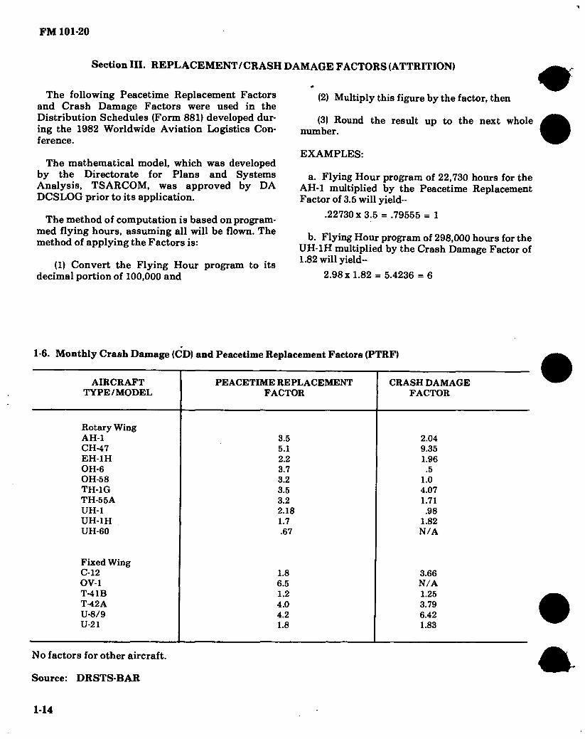
Section III. REPLACEMENT/CRASH DAMAGE FACTORS (ATTRITION)
The following Peacetime Replacement Factors and Crash Damage Factors were used in the Distribution Schedules (Form 881) developed dur- ing the 1982 Worldwide Aviation Logistics Con- ference.
The mathematical model, which was developed by the Directorate for Plans and Systems Analysis, TSARCOM, was approved by DA DCSLOG prior to its application.
The method of computation is based on program- med flying hours, assuming all will be flown. The method of applying the Factors is:
(1) Convert the Flying Hour program to its decimal portion of 100,000 and
(2) Multiply this figure by the factor, then
(3) Round the result up to the next whole number.
EXAMPLES:
a. Flying Hour program of 22,730 hours for the AH-1 multiplied by the Peacetime Replacement Factor of 3.5 will yield--
.22730x3.5 = .79555 = 1
b. Flying Hour program of 298,000 hours for the UH-1H multiplied by the Crash Damage Factor of 1.82 will yield-
2.98 x 1.82 = 5.4236 = 6
1-6. Monthly Crash Damage (CD) and Peacetime Replacement Factors (PTRF)
AIRCRAFT TYPE/MODEL
PEACETIME REPLACEMENT FACTOR
CRASH DAMAGE FACTOR
Rotary Wing AH-1 CH-47 EH-1H OH-6 OH-58 TH-1G TH-55A UH-1 UH-1H UH-60
Fixed Wing C-12 OV-1 T-41B T-42A U-8/9 U-21
3.5 5.1 2.2 3.7 3.2 3.5 3.2 2.18 1.7 .67
1.8 6.5 1.2 4.0 4.2 1.8
2.04 9.35 1.96
.5 1.0 4.07 1.71 .98
1.82 N/A
3.66 N/A 1.25 3.79 6.42 1.83
No factors for other aircraft.
Source: DRSTS-BAR
1-14

FM 101-20
Section IV STANDARD AIRC
b P HARACTERISTICS/PERFORMANCE
Standard aircraft characteristic data contained herein will change as modifications or additions
and deletions of aircraft components or equipment are made.
S3
oc, m
o
Figure 1-1. AH-64A (Apache)
1-15

FM 101-20
OI?]4S6789 IO
SCALE M FHT
DIMENSIONS
Rotor dia 48 Ft. Length:
Rotors operating 58.25 Ft.
Fuselage 49.12 Ft. Span (max
lateral) 17.17 Ft. Height 15.20 Ft. Tread 6.66 Ft. Rotor gnd clear-
ance (static) 10.00 Ft.
15.50 FT
- OUTBOARD PYLONS -
P— 9.05 FT -
n 7.12 FT I 17.17 FT
1X83 FT
4.50 FT
1 I ~lX6.66 FT
* -r 1 OJO FT
vamcAi RffstajcE LINE (WL SO.OO)
17.17 FT
48.00 DIA
4^1 11.145 FT
3.96 FT Li 6J0
2.96 FT
L 0.50 FT MIN CLEARANCE /
BLADE ROTATION
- OJO FT MM
CRITICAL
CLEARANCE
HORIZONTAL
KEF UNE —
(FS 6.00) —“
STA 198.606 FUS 9.166 FT DIA
16.55 FT 29.67 FT
T-r
Wl 215.939 STA 20.00 t 3
H, 6.00 FT STATIC
1.50 FT MIN CRITICAL
* •
g - 9.416 FT
a> Ci- oo STATIC
15.20 FT 3r/l 19^41 FULLY 1. Wl
CONE 1Z59 n 8.10 129JO zato “y STATIC GROUND UNE _L i
34.75 FT
CONE STA 232.40 13J5FT
O
U_J_ 48 45 4.91 FT 2.49 FT
L H L 3.125 1363 FT VERTICAL REFERENCE UNE (WL 50.00)
45.04 FT MAX 066 FT I FT
49.12 FT MAX
57.04 FT
Figure 1-2. Principal Dimensions, AH-64A (Apache)
1-16

1-17
• • • • • 1-7. AH-64A Characteristics
ENGINE MISSION AND DESCRIPTION WEIGHTS
AH-64A
No. and Model Mfr Engine Spec. No
Type Reduction Gear Ratio Tail Pipe Augmentation
.... (2)T700-GE-701
... General Electric DARCOM-CP-
2222-02-701 Free Power Turbine 72.42:1 Fixed Area None
ENGINE RATINGS
Intermediate 1694 SL/STD Max Continuous 1510 SL/STD Contingency 1723 SL/STD
The AH-64A is being developed primarily for destruction of armored vehicles, but is capable of defeating a wide range of other targets. It will provide direct aerial fires as an integral element of the ground units and will be responsive around the clock and under adverse weather conditions. It will contribute highly mobile, effective and accurate anti-armor firepower with the hellfire laser guided anti-armor missile, 30mm chain gun and 2.75 inch rockets. The AH-64A is equipped with an in- tegrated Target Acquisition and Designation Sight (TADS) and a Pilot’s Night Vision Sensor (PNVS). The aircraft is designed to survive against current and future enemy threats on the bat- tlefield.
DEVELOPMENT
LOADING LB.
Empty 11,015 Basic 14,660 Design 14,694 Combat (Primary) 14,694
(Max Alt) 17,650 (Ferry) 20,533
FUEL AND OIL
Fuel: Grade JP-4/5/8 Spec MIL-T-5624J
MIL-T-83133 TECHNICAL PUBLICATIONS
AIRFRAME: (Draft) TM 55-1520-238-10 & CL TM 55-1520-238-23 TM 55-1520-238-23P TM 55-1520-238-PM TM 55-1520-238- MTF TM 55-1520-238- PMD TM 55-1520-238-S TM 55-1520-238-(T)
ENGINE: (Draft) TM 55-2840-248-23
WEAPONS: TM 9-1090-208-23
TM 9-1427-475-23 TM 9-476-23
OPTICAL: TM 9-1270-221-234P
TM 9-1425-476- 23&P
AREA WPN & RKTSYS HFMSL EQUIP FIRE CONTROL SYS
INT HELMET & DISPLAY SIGHT SYS TADS
TM 11-5855-265-23&P PNVS
Date of contract Jun 1973 First flight (similar aircraft) Mar 1975 First acft delivered (Production) Feb 1984
FEATURES PERSONNEL
Not Available Pilot 1 Co-Pilot/Gunner 1
No tanks 4(Extemal) Location Wings Qty .'812 Gal
Oil: Spec MIL-L-7808G/
MIL-L-23699B No. tanks 2 Location Integral w/
Engine Qty 3.65 Gal
AVIONICS/ARMAMENT
Refer to Chapter 2.
FLYAWAY COSTS/NSN
NSN 1520-01-106-9519 Lin Z33149 Costs — Not Available
FM
101-20

1-18 /
1-8. Loading and Performance — Typical Mission AH-64A
Conditions Primary Mission
Mission I
Mission II
Mission III
Mission IV
Ferry Mission
Mission Gross Weight (Take Off) Payload (Expendable Ordnance)
HELLFIRE 2.75' ' Rockets 30MM
Fuel (Usable) Vertical Rate of Climb OGE © 4000 ft,
95°F, 95% IRP Rate of Climb © 80 kts, 4000 ft, 95 °F,
IRP Cruise Speed 0 4000 ft, 95°F, MCP Endurance 0 4000 ft, 95° F Hover Ceiling OGE 95° F, 95% IRP Hover Ceiling IGE 95 °F, 95% IRP Service Ceiling Standard Day, IRP Service Ceiling Single Engine,
Standard Day, IRP Service Ceiling Single Engine,
95 °F, IRP Ferry Range
(lbs) (Ibs/no) (Ibs/no) (lbs/no) (Ibs/no) (lbs)
(FPM)
(FPM) (KTAS) (Hrs) (Ft) (Ft) (Ft)
(Ft)
(Ft) (NM)
14694
788/7
247/320 1624
800
2510 145
1.83 5600
10900 20000
10100
5600
15084
788/8
616/800 1644
440
2375 144
1.83 5300
10200 20000
9200
4600
16242
1576/16
618/802 1624
1942 138
1.69 3100 8500
20000
7000
2850
16242
788/8 1030/38 474/616
1624
1942 139
1.70 3100 8500
20000
7000
2850
16242
2060/76 331/429
1624
1942 140
1.71 3100 6500
20000
7000
2850
20533
77093
800
Conditions Primary Mission Payload
w/Full Fuel
Alternate Mission
IA
Alternate Mission
IIA
Alternate Mission HIA
Alternate Mission IVA
Alternate Mission
VA
Mission Gross Weight (Take Off) Payload (Expendable Ordnance)
Hellfire 2.75' ' Rockets 30MM
Fuel Endurance © Sea Level, Std. Day
(lbs)
(lbs/no) (lbs/no) (lbs/no) (lbs) (hrs)
15512 Same as above
2442 2.59
15882 Same as above
2442 2.57
17060 Same as above
2442 2.50
17060 Same as above
2442 2.51
17060 Same as above
2442 2.52
17650
0 2060/76
824/1200 2442 2.49
J,/ Engine Operating Limit — 8000 ft, 95°F 2/ With External Fuel Tanks .3/ With 20 Knot Headwind 4/ At the Above Mission Gross Weights
• • t • •
FM
101-20

FM 101-20
1-9. Performance Notes — AH-64A.
Formula: Primary Mission — Entire mission performed at 4000 ft, 95°F as follows:
1.
2.
3.
4.
5.
6.
8 minutes at maximum continuous power.
30 minutes at 0-40 KTAS ® PMGW *.
12 minutes at 80-100 KT AS ® PMGW *.
5 minutes at 150 KTAS or at speed limited by IRP ® PMGW.
25 minutes HOGE ® PMGW *.
30 minutes reserve at maximum range speed ® PMGW minus expendable ordnance minus fuel burned off in 1 through 5.
•Compute 1/2 at PMGW (primary mission gross weight) and 1/2 at PMGW less 1/2 the expen- dable ordnance payload and less fuel for items 1 through 5.
Formula: Alternate Mission I — Same as Primary Mission.
Formula: Alternate Mission II — Same as Primary Mission, except time at 800-100 KTAS at 3.6 minutes.
Formula: Alternate Mission III — Same as Primary Mission, except time at 80-100 KTAS is 4.0 minutes.
Formula: Alternate Mission IV — Same as Primary Mission, except time at 80-100 KTAS is 4.4 minutes.
Formula: Ferry Mission — Auxiliary fuel tanks utilized. Twenty knot headwind. A 45 minute fuel reserve at max range speed shall be provided for flights up to 3 hrs in length. For flights over 3 hrs, reserve shall be increased by 10% of the additional fuel at the airspeed and headwind re- quired above. Two minutes at MCP shall be allowed for warm-up and take-off. The mission shall be performed at standard day conditions with takeoff at sea level.
Formula: Mission with Primary Mission Payload and Full Fuel.Entire mission performed at sea level standard day conditions as follows:
1. 8 minutes at maximum continuous power.
2. 25 minutes HOGE ® TOGW *.
3. 3Ó minutes at 0-40 KTAS ® TOGW *.
4. 20.1 minutes @150 KTAS ©TOGW*.
5. 30 minutes at maximum endurance airspeed ® TOGW *.
6. 12 minutes at 80-100 KTAS ® TOGW *.
7. 30 minutes reserve at maximum range airspeed ® TOGW * minus expendable ordnance minus fuel burned off in 1 through 6.
•Compute 1/2 at TOGW (Takeoff gross weight) and 1/2 at TOGW less 1/2 the expendable ord- nance payload and less fuel for items 1 through 6.
Formula: Alternate Mission IA — Same as Mission at Basic Structural Design Gross Weight, except time at 150 KTAS is 19.2 minutes.
Formula: Alternate Mission IIA — Same as Mission at Basic Structural Design Gross Weight, except time at 150 KTAS is 15.2 minutes.
1-19

FM 101-20
1-9. Performance Notes — AH-64A(Con’t)
Formula: Alternate Mission IIIA — Same as Mission at Basic Structural Design Gross Weight, except time at 150 KTAS is 15.5 minutes.
Formula: Alternate Mission IVA — Same as Mission at Basic Structural Design Gross Weight, except time at 150 KTAS is 16.0 minutes.
Formula: Alternate Mission VA — Same as Mission at Basic Structural Design Gross Weight, except time at 150 KTAS is 14.1 minutes.
Performance Reference: System Specification DRC-S-410000B AH-64A
Source: AVRADCOM DRCPM-AAH-SE
1-20
FM 101-20
<7
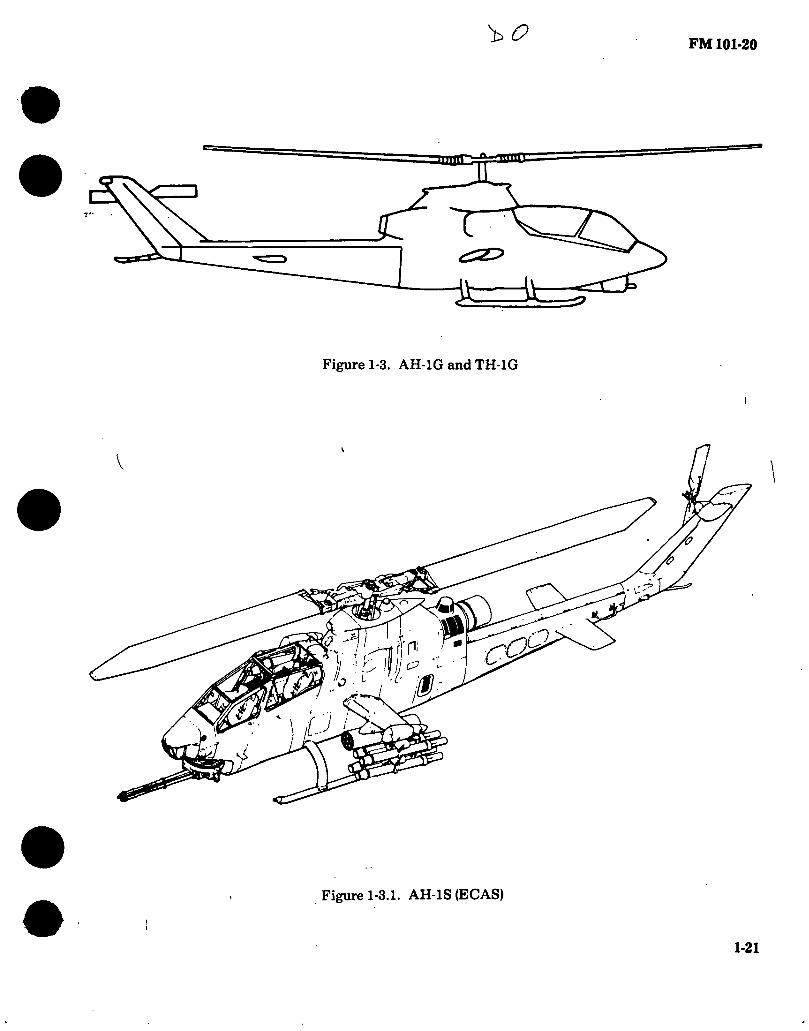
Figure 1-3. AH-1G and TH-1G
I
1
(P
m N
Figure 1-3.1. AH-1S (EGAS)
1-21

FM 101-20
DIMENSIONS-
10FT4IN
3FT6IN
Rotor día 44 Ft. Length:
Rotors operating 52 Ft. 11 In.
Fuselage 45 Ft. 2-1/4 In. Span (max
lateral) 10 Ft. 4 In. I leighl 11 Ft. 7 In.
Tread 7 Ft. 4 In. Rotor gnd clear -
anee (static) 7 Ft. 10 In.
10 FT 2 IN
/°\J3 4FT 10 IN
3FT
h—7FT4IN—1
A 27IN
a u. t
44FT 6FT 2IN
70 P/?
MAXIMUM LENGTH
3.75 IN
7FT 10IN
13FT 61N 52 FT 11 IN
ROTORS TURNING 8FT6IN 14FT4IN
10FT4IN
7
11 FT 7IN
Ü 2FT4.25IN
St
9 FT 2 IN 45 FT 2.25 IN
1FT 1.25IN
Figure 1-4. Principal Dimensions, AH-1G and TH-1G
+ 1-22

1-23 • •
1-10. AH-1G/TH-1G* (Hueycobra) Characteristics.
ENGINE MISSION AND DESCRIPTION WEIGHTS
No. and Model (1)T53-L-13B
Mfr Lycoming Engine Spec. No :.... 104.33 Type Free Power Turbine
Reduction Gear Ratio 0.31 IS
Tail Pipe Fixed Area
Augmentation None
ENGINE RATING
SEA LEVEL
STD SHP
Military 1400
Normal
RPM MIN
6600 30
1250 6600 Cont.
TECHNICAL PUBLICATIONS
AIRFRAME:
TM55-1500-339-S TM55-1520-22 .PM TM55-1520-221-10 & CL TM55-1520-221-23 TM55-1520-221-23P TM55-1520-221-PM TM55-1520-221-MTF TM55-1500-220-PMD
ENGINE: TM55-2840-229-24 TM55-2840-229-23P
Mfr’s Model: BeU 209
The primary missions of this aircraft arethoseof an armed tactical helicopter capable of delivering weapons fire, low altitude high speed flight, search and target acquisition, reconnaissance by fire, multiple weapons fire support, and troop helicopter support The aircraft is capable of performing these missions from prepared or unprepared areas, under day and night VFR conditions within a temperature range of — 25°F to + 125°F.
The gas turbine powered “Hueycobra” is of compact design featuring tandem seating to give both pilot and gunner nearly unlimited visibility. Both crew stations have flight control and fire control systems permitting flexibility in division of functions under all normal and emergency situations.
A mission designed fuselage coupled with the 540 rotor system gives a low vibration level plus increased maneuverability and speed. Four wing stores stations and an integral chin turret provide a high degree of armament versatility with the capa- bility of quickly changing a wide combination of weapons to match the desired mission. Reliability and maintainability are ensured through the use of many UH-1 parts which have been combat proven.
Other features include a crashworthy fuel system with closed circuit refueling capability, and a tractor tailrotor system.
LOADING
Empty
LB.
5809 (C)
Combat Clean Light Scout Heavy Scout Hog
Max. Takeoff Max. Landing
(C) Calculated
8521 (C) 9500 (C) 9500 (C) 9500 (C) 9500 9500
FUEL AND OIL
DEVELOPMENT
Date of contract 4 April 1966 First flight (Similar aircraft) 7 September 1965 First acft delivered 18 September 1966
Fuel: Grade JP-4/5 Spec MIL-T-5624 No. tanks 2 Location Fuselage Q‘y 26 2 gal
OU: Spec MIL-L-7808/
MIL-L-23699 No. tanks 1 Location Fuselage Qty 2.9 gal
FEATURES
Advanced flexible gun turret Armor protection for crew and
critical components. Hardpoints for rockets, and
external stores on wings. Stability Control Augmentation
System (SAS) eliminates stabi- lizer bar and provides a stable gun platform.
PERSONNEL AVIONICS / ARMAMENT
Light Scout, Heavy Scout or Hog Mission
Pilot 1 Gunner 1
Refer to Chapter 2.
UNIT PRICE/NSN Ferry Mission
Pilot Copilot...
AH-1G, NSN 1520-00-999-5821 LINE K29660, UNIT PRICE: Refer to Table 4-1.
*TH-1G. Addition of Instructor Flight Controls and Instrument Panel converts the AH-1G to the TH-1G.
FM
10
1-2
0

1-24
1-11. Loading and Performance — Typical Mission AH-1G and TH-1G.
CONDITIONS MISSION I LIGHT SCOUT
MISSION II HEAVY SCOUT
MISSION III HOG
MISSION IV
FERRY (CLEAN)
TAKEOFF WEIGHT (lb)
Fuel at 6.5 Ibs/gal (Grade JP-4) (lb)
Payload (lb)
Takeoff Power Loading (lb SHP)
Disk Loading (lb sq ft)
Autorotation Speed (Min R/D) (kn)
Takeoff Ground Run at SL (ft)
Takeoff to Clear 50 ft (ft)
Vertical Rate of Climb at SL .(fpm)
Maximum Rate of Climb at SL (fpm)
Speed for Max R/C at SL (kn)
Time: SL to 5000 ft (min)
Time: SL to 10,000 ft (min)
Service Ceiling (100 fpm) (ft)
Absolute Hovering Ceiling (ft)
COMBAT RANGE (nmi)
Average Cruise Speed (kn) Cruising Altitude (Initial) (ft)
Cruising Altitude (Final) (ft)
Total Mission Time .(hr)
COMBAT RADIUS (nmi)
Average Cruise Speed 4 (kn)
Cruising Altitude (Outbound)(Min/Max) .(ft)
Cruising Altitude (Inbound) (ft) Total Mission Time .(hr)
9171 1572 1792
8.34 6.04
65 105 267
1330 64
3.7 8.3
12450
141.1 133
6350/9800 10000
2.4
9500 1277
2416 8.64 6.25
65 127 344
1230 65 4.0 9.2
11420
95.3 125
5350/7250 10000
1.8
9500 1025
2668 8.64 6.25
65 127 344
1230 65 4.0 9.2
11420
70.1 125
5600/7200 10000
1.4
7671 1672
192
6.97 5.05
65 0 0
1210 1860
60 2.7 5.6
18200 10650
371.1 141
10000 10000
2.7
• •
FM
101-20

1-25 • • • • •
1-11. Loading and Performance — Typical Mission AH-1G and TH-1G (Con’t).
CONDITIONS MISSION I
LIGHT SCOUT
MISSION II
HEAVY SCOUT
MISSION III
HOG
MISSION IV
FERRY (CLEAN)
COMBAT WEIGHT (lb) Combat Altitude (ft) Combat Speed (kn) Combat Climb (fpm) Combat Ceiling (500 ft/min) (ft) Service Ceiling (100 ft/min) (ft) Absolute Hovering Ceiling (ft) Takeoff Ground Run at SL (ft) Takeoff to Clear 50 ft (ft) Maximum Rate of Climb at SL (fpm) Speed for Max R/C at SL (kn) Max Speed at SL (kn) Basic Speed at 5000 ft (kn)
LANDING WEIGHT (lb) Ground Roll at SL (ft) Total from 50 ft (ft)
8148 Sea Level
140 1665
15350 16300 8500
0 0
1665 62
140 142
7413 0 0
7937 Sea Level
137 1745
16250 17100 9450
0 0
1745 61
137 139
7383 0 0
7020 Sea Level
132 2140
20200 21000 13750
0 0
2140 58
132 135
6578 0 0
6231 10000
155 2170
23800 24550 17700
0 0
2490 54
149 154
6231 0 0
FM
101-20
FM 101-20
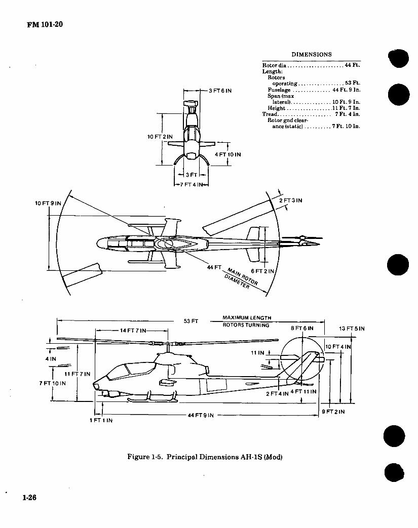
DIMENSIONS
10FT9IN
3 FT 6 IN
Rotor dia 44 Ft. Length:
Rotors operating 53 Ft.
Fuselage 44 Ft. 9 In. Span (max
lateral) 10 Ft. 9 In. Height 11 Ft. 7 In.
Tread 7 Ft. 4 In. Rotor gnd clear-
ance (static) 7 Ft. 10 In.
10 FT 2 IN
10 N
3 FT
I—7 FT 4 N—
> 2 FT 3 IN
a V n
44 FT FT N
*0 0/?
MAXIMUM LENGTH
7 FT 10 IN
13 FT 5 IN
53 FT ROTORS TURNING
8 FT 6 IN 14 FT 7 IN
189 10FT4 N
11 IN J
Z 4 IN
11 FT7IN
2FT4IN4Frri1IN
1 Ü Ss
9 FT 2 IN 44 FT 9 IN
1 FT 1 IN
Figure 1-5. Principal Dimensions AH-1S (Mod)
»
1-26
ill
• • • • •
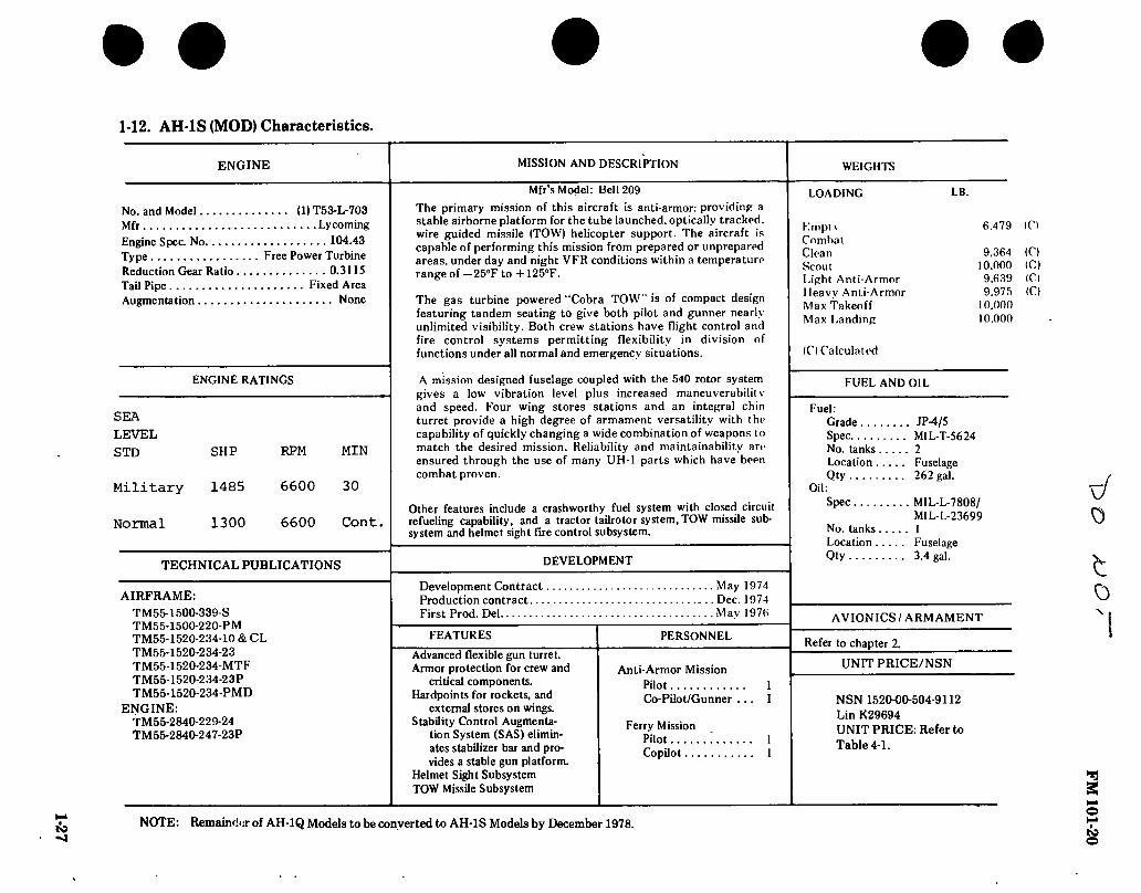
1-12. AH-1S (MOD) Characteristics.
ENGINE MISSION AND DESCRIPTION
Mfr’s Model: Bell 209
No. and Model Mfr Engine Spec. No Type Reduction Gear Ratio Tail Pipe - Augmentation
(1) T53-L-703 Lycoming 104.43 Free Power Turbine 0.3115 Fixed Area None
The primary mission of this aircraft is anti-armor: providing a stable airborne platform for the tube launched, optically tracked, wire guided missile (TOW) hehcopter support. The aircraft is capable of performing this mission from prepared or unprepared areas, under day and night VFR conditions within a temperature range of — 25°F to + 125”F.
The gas turbine powered “Cobra TOW” is of compact design featuring tandem seating to give both pilot and gunner nearly unlimited visibility. Both crew stations have flight control and fire control systems permitting flexibility in division of functions under all normal and emergency situations.
ENGINE RATINGS
SEA
LEVEL
STD
Military
Normal
SHP RPM MIN
1485 6600 30
1300 6600 Cont.
TECHNICAL PUBLICATIONS
AIRFRAME:
TM55-1500-339-S TM55-1500-220-PM TM55-1520-234-10 & CL TM55-1520-234-23 TM55-1520-234-MTF TM55-1520-234-23P TM55-1520-234-PMD
ENGINE: TM55-2840-229-24 TM55-2840-247-23P
A mission designed fuselage coupled with the 540 rotor system gives a low vibration level plus increased maneuverabilil v and speed. Four wing stores stations and an integral chin turret provide a high degree of armament versatility with the capability of quickly changing a wide combination of weapons to match the desired mission. Reliability and maintainability are ensured through the use of many UH-1 parts which have been combat proven.
Other features include a crashworthy fuel system with closed circuit refueling capability, and a tractor tailrotor system, TOW missile sub- system and helmet sight fire control subsystem.
DEVELOPMENT
Development Contract Production contract First Prod. Del
FEATURES
Advanced flexible gun turret. Armor protection for crew and
critical components. Hardpoints for rockets, and
external stores on wings. Stability Control Augmenta-
tion System (SAS) elimin- ates stabilizer bar and pro- vides a stable gun platform.
Helmet Sight Subsystem TOW Missile Subsystem
... May 1974
... Dec. 1974 . . . May 1976
PERSONNEL
Anti-Armor Mission Pilot 1 Co-Pilot/Gunner ... 1
Ferry Mission Pilot ! 1 Copilot 1
WEIGHTS
LOADING LB.
Empt \ Combat Clean Scout Light Anti-Armor Heavy Anti-Armor Max Takeoff Max Landing
6.479 (Cl
9.364 10.000 9,639 9.975
10.000 10.000
(C) (Cl (Cl (C)
(C) Calculated
FUEL AND OIL
Fuel: Grade JP-4/5 Spec MIL-T-5624 No. tanks 2 Location Fuselage Qty 262 gal.
Oil: Spec MIL-L-7808/
MIL-L-23699 No. tanks 1 Location Fuselage Qty 3.4 gal.
AVIONICS/ARMAMENT
Refer to chapter 2.
UNIT PRICE/NSN
NSN 1520-00-504-9112 Lin K29694 UNIT PRICE: Refer to Table 4-1.
sJ 0
o
2
NOTE: Remainder of AH-1Q Models to be converted to AH-1S Models by December 1978. Is9

FM 101-20 1) O
DIMENSIONS
10 FT 8 IN
3 FT 6 IN.
Rotor dia 44 Ft. Length:
Rotors operating 53 Ft.
Fuselage 44 FT 7 In. Span (max
lateral) 10 Ft. 8 In. Height 11 Ft. 7 In. Tread 7 Ft. 4 In. Rotor gnd clear-
ance (static) 7 Ft. 10 In. 9FT11 IN □
4 FT 10 IN
3FT
7FT4IN
> 2 FT 3 IN
5 a j
u_ i 44FT
FT N 2'* O, 70
9» *4
MAXIMUM LENGTH
11FT7IN
7 FT 10 IN.
13 FT 6 IN.
53 FT ROTORS TURNING 8 FT 6 IN
14 FT 7 N.
11 N 10'6
7 4 IN.
5 FT 2 FT 4 IN
&
9 FT 3 IN. 44 FT 7 IN.
1 FT 1 IN.
Figure 1-6. Principal Dimensions AH-1S (Prod)
1-28

1-29
! I
1-13. AH-1S (Prod) Characteristics.
ENGINE
No. and Model (1) T53—L-703 Mfr Lycoming Engine Spec. No 104.43 Type Eree Power Turbine Reduction Gear Ratio 0.31 IS Tail Pipe Fixed Area Augmentation None
ENGINE RATINGS
SEA LEVEL STD SHP
Military 1485
Normal 1290
RPM MIN
6600 30
6600 Cont.
TECHNICAL PUBLICATIONS
AIRFRAME: TM55-1520-236-10 and CL TM55-1520-236-23 TMSS-l500-339-S TM55-1500-220-PM TM55-1520-236-MTF TM55-1520-236-23P 11155-1520-236-PMD
ENGINE: TM55-2840-229-24 1M55-2840-247-23P
MISSION AND DESCRIPTION
Mfr’s Model: Bell 209
The primary mission of this aircraft is anti-tank, providing a stable airborne platform for the tube launched, optically tracked, wire guided missile (TOW) helicopter support. The aircraft is capable of performing this mission from prepared or unprepared areas, under day and night VFR conditions within a temperature range of -25°F to +12ö,F. The gas turbine powered “Cobra-TOW" is of compact design featuring tandem seating to give both pilot and gunner nearly unlimited visibility. Both crew stations have flight control and fire control systems permitting flexibility in division of functions under all normal and emergency situations.
A mission designed fuselage coupled with the 540 rotor system gives a low vibration level plus increased maneuverability and speed. Four wing stores stations and an integral chin turret provide a high degree of armament versatility with the capability of quickly changing a wide combination of weapons to match the desired mission. Reliability and maintainability ire ensured through the use of many UH-1 parts which have been combat proven.
Other features include a crashworthy fuel system with closed circuit refueling capability, and a tractor tailrotor system, TOW missile sub- system and helmet sight fire control subsystem.
DEVELOPMENT
Development Contract. Production contract ... First Prod. Del
. Jan 1975 .Dec 1975
. Mar 1977
FEATURES
Advanced flexible gun turret. Armor protection for crew and
critical components. Hardpoints for rockets, and
external stores on wings. Stability Control Augmenta-
tion System (SAS) elimin- ates stabilizer bar and pro- vides a stable gun platform.
Helmet Sight Subsystem TOW Missile Subsystem
PERSONNEL
Anti-Armor Mission Pilot : i
Co-PUot/Gunner 1
Ferry Mission Pilot 1 Co-Pilot 1
WEIGHTS
LOADING
Empty Combat Clean Scout Light Anti-Armor Heavy Anti-Armor Max Takeoff Max Landing
(c) Calculated
LB.
6,479 <C>
9,364 (C)
9.639 9,975
10,000 10.000
(C) (C)
FUEL AND OIL
Fuel: Grade JP-4/5 Spec M1L-T-5624 No. tanks 2 Location Fuselage Qty 262 gal.
Oil: Spec MIL-L-7808/
MIL-L-23699 No. tanks 1 Location Fuselage Qty 2.9 gal.
b/ Ö
AVIONICS/ ARMAMENT
Refer to chapter 2.
UNIT PRICE/NSN
NSN 1520-00-504-9112 Lin K29694. UNIT PRICE: Refer to Table 4-1.
«
FM
101-20

1-30 S
1-14. Loading and Performance — Typical Mission AH-1S (MOD) and (PROD).
CONDITIONS MISSION I
SCOUT
MISSION II LIGHT
ANTI-ARMOR
MISSION III HEAVY
ANTI-ARMOR
MISSION IV FERRY
(CLEAN)
TAKEOFF WEIGHT (lb) Fuel at 6.5 Ibs/gal (Grade JP-4) (lb) Payload (lb) Takeoff Power Loading (lb SHP) Disk Loading (Ibsqft) Autorotation Speed (Min R/D) (kn) Takeoff Ground Run at SL (ft) Takeoff to Clear 50 ft (ft) Vertical Rate of Climb at SL (fpm) Maximum Rate of Climb at SL (fpm) Speed for Max R/C at SL (kn) Time: SL to 5000 ft (min) Time: SL to 10,000 ft (min) Service Geling (100 fpm) (ft) Absolute Hovering Ceiling (ft)
COMBAT RANGE (nmi) Average Cruise Speed (kn) Cruising Altitude (Initial) (ft) Cruising Altitude (Final) (ft) Total Mission Time (hr)
COMBAT RADIUS (nmi) Average Cruise Speed (kn) Cruising Altitude (Outbound) (Min/Max)..(ft) Cruising Altitude (Inbound) (ft) Total Mission Time (hr)
10,000 1,287 3961 7.75 6.58
65 0 0
320 1,620
64 3.1 8.6
12,200 11,600
9,639 1,684 3216 7.47 6.34
65 0 0
610 1,740
65 2.8 5.7
14,800 8,000
9,975 1,684 3432 7.73 6.56
65 0 0
335 1,640
65 3.0 6.1
12,300 3,800
9,364 1,684 2875 7.25 6.16
65 0 0
850 1,850
60 2.7 5.4
15.000 10,200
320 130
10.000 10,000
2.6
1.4 2.1 2.0 2.4
to o
• •

FM 101-20
—10 FT 8.2 IN.—I
h “t— 3 FT 6.0 IN.
9 FT 11.7 IN.
'if 0
1 ti-û—I □ —o-0 1 )
4 FT 10.4 IN.
l 3 FT 0.0 IN.
1*7 FT0.0 INrl
6 FT 11.14 IN - 30 IN FT 68 IN r
“1 2 FT 58 IN
it 2.81 IN
□ — □ IN FT
44 FT DIA «-¿i -A FT 9.38 IN.
53 FT 0.5 IN 11.5 IN
14 FT 7.6 IN.
a s-, 8 FT 6 IN.
2 FT 4.2 IN t
O I- z
& c s M H
FT 1.9 IN. GROUND LINE AT MAX GROSS WEIGHT
44 FT 7.0 IN.
3 FT 8.37 IN.
L 5 FT 0.3 IN -
-45 FT 8.0 IN.
Figure 1-7. Principal Dimensions AH-lS (EGAS)
1-31
Nl £
9 Id
£ L
I—
Nl
19 Id
01

1—
12 F
T 1
.1
IN.
i 7
FT 1
0.1
IN
rn
FM 101-20
9 FT 11.7 IN.
— 10 FT 8.2 IN ■n 3 FT 6.0 IN.
¥
4 FT 10.4 IN
“-O—1 □!—(H 3 FT 0.0 IN.
1*7 FT 0.0 INrl
6 FT 11.14 IN 30 IN —1 FT 68 IN
2 FT
2.81 IN. H —
58 IN L
Q FT N
44 FT DIA «i; FT 9.38 IN
53 FT 0.5 IN.
11.5 IN. 14 FT 7.6 IN
Oi
8 FT 6 IN
3 2 FT 4.2 IN
3 FT 8.37 IN.
1 FT 1.9 GROUND LINE AT MAX GROSS WEIGHT
44 FT 7.0 IN. 5 FT 0.3 IN -
-45 FT 8.0 IN.
Figure 1-8. Principal Dimensions AH-1S (Modernized)
1-32
10 F
T 6
.1
IN —
I
13 F
T 6
.3 I
N
1-33
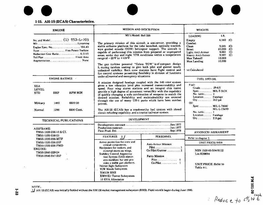
1-15. AH-1S (EGAS) Characteristics.
ENGINE
No. and Model (1) T53—L—703 Mfr Lycoming Engine Spec. No 104.43 Type Eree Power Turbine Reduction Gear Ratio 0.3115 Tail Pipe Kixed Area Augmentation None
ENGINE RATINGS
SEA LEVEL STD SHP RPM MIN
Military 1485 6600 30
Normal 1290 6600 Cont.
TECHNICAL PUBLICATIONS
AIRFRAME: TM55-1520-236-10 & CL TM55-1520-236-23 TM55-1520-236-MTF TM55-1520-236-23P TM55-1520-236-PMD
ENGINE: TM55-2840-229-24 TM55-2840-247-23P
MISSION AND DESCRIPTION
Mfr’s Model: Bell 209
The primary mission of this aircraft is anti-armor, providing a stable airborne platform for the tube launched, optically tracked, wire guided missile ITOW) helicopter support. The aircraft is capable of performing this mission from prepared or unprepared areas, under day and night VFR conditions within a temperature range of — 25°F to +125“F.
The gas turbine powered “Cobra TOW” is of compact design ft. ituring tandem seating to give both pilot and gunner nearly unlimited visibility. Both crew stations have flight control and fire control systems permitting flexibility in division of functions under all normal and emergency situations.
A mission designed fuselage coupled with the 540 rotor system gives a low vibration level plus increased maneuverability and speed. Four wing stores stations and an integral chin turret provide a high degree of armament versatility with the capability of quickly changing a wide combination of weapons to match the desired mission. Reliability and maintainability are ensured through the use of many UH-1 parts which have been combat proven.
The AH-IS (EGAS) has a crashworthy fuel system with closed circuit refueling capability, and a tractor tailrotor system.
DEVELOPMENT
Development contract Production contract .., First Prod. Del
.Jan 1977
.Jun 1977 . Sep 1978
FEATURES u Armor protection for crew and
critical components. Hardpoints for rockets, and
external stores on wings. Stability Control Augmenta-
tion System (SAS) elimin- ates stabilizer bar and pro- vides a stable gun platform.
Helmet Sight Subsystem TOW Missile Subsystem XM138 RMS XM97E1 Turret Subsystem 10 KVA Alternator
PERSONNEL
Anti-Armor Mission Pilot 1
Co-Pilot/Gunner 1
Ferry Mission Pilot Co-Pilot ..
WEIGHTS
LOADING
Empty Combat Clean Scout Light Anti-Armor Heavy Anti-Armor Max Takeoff Max Landing
(c) Calculated
LB.
6,580 (C)
9,541 10,000 9.661 9,987
10,000 10,000
1C) (C) (C) (C)
FUEL AND OIL
Fuel : Grade JP-4/5 Spec MIL-T-5624 No. tanks 2 Location Fuselage Oty 262 gal.
Oil: Spec MIL-L-7808/
M1L-L-23699 No. tanks 1 Location Fuselage Oty 2.9 gal.
AVIONICS/ ARMAMENT
Refer to chapter 2.
UNIT PRICE/NSN
NSN 1520-00-504-9112 Lin K29694
UNIT PRICE: Refer to Table 4-1.
NOTE:
-U AH-lS (EGAS) was initially fielded without the XM138 rocket management subsystem (RMS). Field retrofit began during June 1980.
UC Ç_ ~fû ¿'2
lucí.
FM
101-20

1-34
1-16. AH-1S (Modernized) Characteristics.
ENGINE MISSION AND DESCRIPTION WEIGHTS
No. and Model (1) T53-L—703 Mfr Lycoming Engine Spec. No 104.43 Type Eree Power Turbine Reduction Gear Ratio 0.31 IS Tail Pipe l ixed Area Augmentation None
ENGINE RATINGS
SEA LEVEL STD SHP RPM MIN
Military 1485 6600 30
Normal 1290 6600 Cont.
TECHNICAL PUBLICATIONS
AIRFRAME: TM55-1520 TM55-1520 TM55-1520 TM55-1520 TM55-1520 TM55-1520' TM55-1520- TM55-1500 TM55-1500-
ENGINE: TM55-2840- TM55-2840-
-236-10 & 10CL -239-10 &10CL -236-23 -239-23 236-23P -239-23P -236-MTF 220-PM 220-PMD
229-24 247-23P
Mfr’s Model: Bell 209
The primary mission of this aircraft is anti-armor, providing a stable airborne platform for the tube launched, optically tracked, wire guided missile (TOW) helicopter support. The aircraft is capable of performing this mission from prepared or unprepared areas, under day and night VFR conditions within a temperature range of — 250F to +125nF.
The gas turbine powered “Cobra TOW” is of compact design featur- ing tandem seating to give both pilot and gunner nearly unlimited visibility. Both crew stations have flight control and fire control systems permitting flexibility in division of functions under all nor- mal and emergency situations. The Modernized Cobra has an im- proved fire control system and doppler navigation system.
A mission designed fuselage coupled with the 540 rotor system gives a low vibration level plus increased maneuverability and speed. Four wing stores stations and an integral chin turret provide a high degree of armament versatility with the capability of quickly changing a wide combination of weapons to match the desired mission. Reliability and maintainability are ensured through the use of many UH-1 parts which have been combat proven.
The AH-1S (Modernized) has a crashworthy fuel system with closed circuit refueling capability, and a tractor tailrotor system.
DEVELOPMENT
Development contract Production contract ... First Prod. Del
.Jan 1977 . Jun 1977 . Sep 1978
FEATURES _L/ Armor protection for crew and
critical components. Hardpoints for rockets, and
external stores on wings. Stability Control Augmenta-
tion System (SAS) elimin- ates stabilizer bar and pro- vides a stable gun platform.
Helmet Sight Subsystem TOW Missile Subsystem XM138 RMS XM97E1 Turret Subsystem 10 KVA Alternator
PERSONNEL
Anti-Armor Mission Pilot 1
Co-Pilot/Gunner 1
Ferry Mission Pilot Co-Pilot • •
LOADING
Empty Combat Clean Scout Light Anti-Armor Heavy Anti-Armor Max Takeoff Max Landing
(c) Calculated
LB.
6,598 (C)
9,541 10,000 9,661 9.987
10.000 10.000
(C) (C) (C) (C)
FUEL AND OIL
l-ucl. Grade JP-4/5 Spec MIL-T-5624 No. tanks 2 Location Fuselage Oty 262 gal.
Oil: Spec MIL-L-7808/
MIL-L-23699 No. tanks I Location Fuselage Oty 2.9 gal
AVIONICS/ARMAMENT
Refer to chapter 2.
UNIT PRICE/NSN
NSN 1520-00-504-9112 Lin K29694
UNIT PRICE: Refer to Table 4-1.
FM
101-20

1-35 • • • • •
1-17. Loading and Performance — Typical Mission AH-1S (EGAS and MODERNIZED).
CONDITIONS MISSION I
SCOUT
MISSION II LIGHT
ANTI-ARMOR
MISSION III HEAVY
ANTI-ARMOR
MISSION IV FERRY
(CLEAN)
TAKEOFF WEIGHT (lb) Fuel at 6.5 Ibs/gal (Grade JP-4) (lb) Payload (lb) Takeoff Power Loading (lb SHP) Disk Loading (Ibsqft) Autorotation Speed (Min R/D) (kn) Takeoff Ground Run at SL (ft) Takeoff to Clear 50 ft (ft) Vertical Rate of Climb at SL (fpm) Maximum Rate of Climb at SL (fpm) Speed for Max R/C at SL (kn) lime: SL to 5000 ft (min) Time: SL to 10,000 ft (min) Service Geling (100 fpm) (ft) Absolute Hovering Ceiling (ft)
COMBAT RANGE (nmi) Average Cruise Speed (kn) Cruising Altitude (Initial) (ft) Cruising Altitude (Final) (ft) Total Mission Time (hr)
COMBAT RADIUS (nmi) Average Cruise Speed (kn) Cruising Altitude (Outbound) (Min/Max)..(ft) Cruising Altitude (Inbound) (ft) Total Mission Time (hr)
10,000 1,101 3,461 7.75 6.58
65 0 0
320 1,620
64 3.1 8.6
12,200 11,600
9,661 1,684 3,081
7.47 6.34
65 0 0
610 1,740
65 2.8 5.7
14,800 8,000
9,987 1,532 3,407
7.73 6.56
65 0 0
335 1,640
65 3.0 6.1
12,300 3,800
9,541 1,684 2,961 7.25 6.16
65 0 0
850 1,850
60 2.7
15.000 10,200
320 130
10.000 10,000
2.6
1.4 2.1 2.0 2.4
FM
101-20

1-18. Loading and Performance — Typical Mission AH-1S (MOD) (PROD) (EGAS and MODERNIZED).
CONDITIONS MISSION I SCOUT
MISSION II LIGHT
ANTI-ARMOR
MISSION III HEAVY
ANTI-ARMOR
MISSION IV FERRY
(CLEAN)
COMBAT WEIGHT (lb) Combat Altitude (ft) Combat Speed (kn) Combat Climb (fpm) Combat Ceiling (500 ft/min) (ft) Service Ceiling (100 ft/min) (ft) Absolute Hovering Ceiling (ft) Takeoff Ground Run at SL (ft) Takeoff to Clear 50 ft (ft) Maximum Rate of Climb at SL (fpm) Speed for Max R/C at SL (kn) Max Speed at SL (kn) Basic Speed at 5000 ft (kn)
LANDING WEIGHT. Ground Roll at SL... Total from 50 ft
(lb) .(ft) .(ft)
9,500 Sea Level
Oto 130 1,800
14,800
0 0
1,800 64
140 140
8,513 0 0
9,140 Sea Level
Oto 130 1,800
16,000
0 0
1,800 64
140 140
7,923 0 0
9,400 Sea Level
Oto 130 1,800
14,800
0 0
1,800 64
140 140
8,043 0 0
8,600 10,000
140 2,000
19,000
0 0
2,000 64
140 140
7,864 0 0
101-20

FM 101-20
1-19. Performance Notes, AH-1G (Cobra - TOW).
LIGHT SCOUT MISSION - Armed Tactical Helicopter — Radius Start engine; warm-up, takeoff, and climb on course at normal power to 6350 feet initial cruise altitude. Maintain 55-feet-per-minute rate of climb at cruise speed to an altitude of 9800 feet. Descend to sea level and fire rockets during a period of ten (10) minutes combat at normal power. Climb on course to 10,000 feet at normal power and return to home base at cruise speed. Range free allowances are two (2) minutes of normal power for warm-up and takeoff, ten (10) minutes of combat time at normal power, plus ten percent of initial fuel for landing and reserve.
HEAVY SCOUT MISSION - Armed Tactical Helicopter — Radius Start engine, warmup, takeoff, and climb on course at normal power to 5350 feet initial cruise altitude. Maintain 41.6 feet-per-minute rate of climb at cruise speed to an altitude of 7250 feet. Descend to sea level and fire rockets during a period of ten (10) minutes combat at normal power. Climb on course to 10,000 feet at normal power and return to home base at cruise speed. Range free allowances are two (2) minutes of normal power for warm-up and takeoff, ten (10) minutes of combat time at normal power, plus ten percent of initial fuel for landing and reserve.
HOG MISSION — Armed Tactical Helicopter — Radius Start engine, warm-up, takeoff, and climb on course at normal power to 5600 feet initial cruise altitude. Maintain 50-feet-per-minute rate of climb at cruise speed to an altitude of 7200 feet. Descend to sea level
and fire rockets during a period of ten (10) minutes combat at normal power. Climb on course to 10,000 feet at normal power and return to home base at cruise speed. Range free allowances are two (2) minutes of normal power for warm-up and takeoff, ten (10) minutes of combat time at normal power, plus ten percent of initial fuel for landing and reserve.
FERRY MISSION - Clean (Without Auxiliary Tanks) - Range Start engine, warm-up, takeoff, and climb on course at normal power to 10,000 feet initial cruise altitude. Fly out at cruise speeds until ninety percent of initial fuel is consumed and land at remote base. Range free allowance include two (2) minutes at normal rated power for warm-up and takeoff, and ten percent of initial fuel for landing and reserve.
GENERAL NOTES: a. Cruise speed as used above denotes airspeed
for long-range operation and is the greater of the two speeds at which ninety-nine percent of the maximum miles per pound of fuel are attainable at the momentary weight and altitude.
b. Data do not include ground effect.
PERFORMANCE BASIS: a. Power required is based upon “Engineering
Phase B Flight-Test Data”.
b. Power available and fuel flow are based on Lycoming Model Specification No. 104.33, and includes particle separators and filters.
NOTE: Performance Notes Not Available for AH-1S Models.
Source: TSARCOM-DRCPM-CO
1-37

FM 101-20
Figure 1-9. CH-47A, B, C and D (Chinook), typical (minor differences apparent between A, B, C and D models)
1-38

FM 101-20
— 12 FT 5 IN —
w >1
11 FT. 11 IN
DIMENSIONS
Rotor dia 59 Ft. 1-1/4 In. Length:
Rotor operating 97 Ft. 6-1/2 In.
Rotors folded 51 Ft. Fuselage 51 Ft.
Height 18 Ft. 6-1/2 In. Tread H Ft. 11 In. Main rotor gnd clearance:
Idling (fwd) 10 Ft. 11 In. (aft) 18 Ft. 9 In.
Static (fwd) 7 Ft. 8 In. (aft) 17 Ft. 1 In.
2 Î-
97 FT 6 1/2 IN
*17 FT 1 IN STATIC
19.2 IN. MIN GND CLEARANCE
* CONTROLS NEUTRAL
Figure 1-10. Principal Dimensions, CH-47A (Chinook)
1-39

OM
1-20. CH-47A (Chinook) Characteristics.
ENGINE MISSION AND DESCRIPTION WEIGHTS
No. & model .. (2) T55-L-7B Mfr Lycoming Engine spec No .. T55-L-7/7B 124.20-A T55-L-7C 124.31
ENGINE RATINGS
SHP RPM ALT MIN T55-L-7 Military 2650 15,150 SL 30 Normal 2250 15,000 SL Cont.
T55-L-7B Military 265015,800 SL 30 Normal 225015,000 SL Cont.
T55-L-7C Max 285016,000 SL 10 Military 285015,750 SL 30 Normal 250015,350 SL Cont.
TECHNICAL PUBLICATIONS
Mfr’s Model: Vertol The principal mission of the CH-47A helicopter is the transport of
cargo, troops, and equipment within the combat area. In addition, this helicopter is suitable for special support functions. It is suitable for operations during day, night, visual, and instrument conditions.
The CH-47A helicopter is a twin-turbine-engine, tandem rotary-wing aircraft. It is powered by two Lycoming T55-L-7 shaft turbine engines mounted on the aft fuselage. The engines simultaneously drive two tandem three-bladed rotary wings through a combining transmission, drive shafting, and reduction transmission. The forward transmis- sion is mounted in the pylon above the cockpit. The aft transmis- sion, the combining transmission, and drive shafting are located in the aft pylon section. A gas-turbined auxiliary power unit, used for starting the engines, is mounted in the aft pylon section. Pods on the sides of the fuselage contain fuel tanks. The helicopter is equipped with nonretractable quadricycle landing gear. The aft wheels are full-swivel type. The entrance door is located at the forward right side of the cabin fuselage section. At the rear of the cabin fuselage section is a hydraulically powered loading ramp. A 16,000 pound capacity cargo hook assembly is provided for transporting external loads. Cargo compartment capacity same for all models (1450 cubic ft.).
DEVELOPMENT
27 June 1960 6 September 1961 Completed May 1967
PERSONNEL
Date of contract . First flight . . . . Production status
CAPACITIES
AIRFRAME: TM 55-1500-210-MTF TM 55-1500-210-L TM 55-1520-209-CL TM 55-1520-209-PMS TM 55-1520-209-10 TM 55-1520-209-23 TM 55-1520-209-23P TM 55-1520-241-S DMWR 55-1500-210
Cargo compartment: Floor 228-3/4 sq ft Length 30 ft, 6 in. Width 7 ft, 6 in. Height 6 ft, 6 in. Volume 1487 cu ft
Crew (normal) 4 Troops 33 Litters 24
ENGINE: TM 55-2840-234-24/1 TM 55-2840-234-23P TM 55-2840-249-23 DMWR 55-2840-106
Forward door: Height Width
Cargo ramp door: Length Width
5 ft, 6 in. 3 ft
6 ft, 6 in. 7 ft, 6 in.
Empty (SPFG) . Design gross wt. Max alt gross wt
Max takeoff . . Max landing . .
LB 18,084 28,550 33.000 33.000 33.000
L.F.
2.67 2.00 2.00 2.00
FUEL AND OIL
Fuel: Grade JP-4 Spec MIL-T-5624 No. tanks:
Nacelle .... (2) 620 gal (50 percent self-sealing)
630 gal (non- self-sealing)
566 gal (crash Oil: resistant)
Spec Temps above
25'" F MILL-23699 Temps below
25 r .... No. tanks. . . . Location ....
Qty
MIL-L-7808 2 Integral with
engine 7 gal
AVIONICS /ARMAMENT
Refer to chapter 2.
UNIT PRICE/NSN
CH-47A, NSN 1520-00-633-6836, LIN K30378, UNIT PRICE: Refer to Table 4-1.
o
• • • • •
FM
101-2
0

FM 101-20
1-21. Loading and Performance — Typical Mission, CH-47A (Chinook).
CONDITIONS MISSION MISSION MISSION
FERRY
I II HI
Gross weight (lb)
Weight empty (lb)
Payload (lb)
Radius of action (nmi)
Ferry range (nmi)
Cruise altitude (ft)
Cruise speed (kn)
^Max @ SL military power (kn)
^Max @ SL normal power (kn)
^Max @ 5000 ft, normal power (kn)
Hover ceiling OGE 95°F, military power, std atmosphere (ft)
Hover ceiling IGE military power, std atmosphere . . (ft)
Service ceiling
Normal power (ft)
Military power 1 eng out (ft)
R/C Max - military power - SL (ft/min)
28,262
17,932
6000
100
SL
130
130
130
114
6000
11.900
11.900
6000
2750
33,000
18,112
13,400
20
SL
110
110
110
94
7900
9200
9200
1400
2160
33,000
17,552
866
6000
110
110
110
94
7900
9200
9200
1400
2166
1. All performance based on NASA standard atmosphere unless otherwise noted. 2. ^Max reflects airspeed limitations specified in TM55-1520-209-10. 3. CH-47A model specifications 114-X-601.
1-22. Performance Notes, CH-47A (Chinook).
FORMULA: MISSION I
Deliver 6000-pound internal payload to any point 100 nautical miles and return with 3000-pound inter- nal payload. Cruise at sea level. Land with 10 percent of initial fuel reserve.
FORMULA: MISSION II
Deliver 13,400-pound external payload to any point 20 nautical miles and return. Equivalent flat
Source: TSARCOM-DRSTS-WC
plate of external cargo = 26 sq ft. Cruise at sea level. Return with fuel reserve for 10-minute cruise at return gross weight.
FORMULA: MISSION III
Ferry Range of 866 nautical miles. Land with 10 percent of initial fuel reserve. Climb to 6000 feet, 256 nautical miles. Cruise 6000 feet for 610 nautical miles. Total ferry time: 7 hours, 50 minutes.
141

FM 101-20
DIMENSIONS
-12 FT 5 IN.*l
■h 10 FT 6 IN
Rotor dia 60 Ft. Length:
Rotors operating 97 Ft. 6-1/2 In.
Rotors folded 50 Ft. 9 In. Fuselage 50 Ft. 9 In.
Height (overall 18 Ft. 6-1/2 In. Tread 11 Ft. 11 In. Rotor ground clearance:
Static fwd 7 Ft. 4-3/4 In. Idling fwd 10 Ft. 11 In.
2 t
iP
97 FT 6-1/2 IN.
18 FT 6-1/2 IN.
LQ), Q O O O 10 FT 11 IN.
1 °56
50 FT 9 IN.
L—18IN. MINGND CLEARANCE
Figure 1-11. Principal Dimensions, CH-47B and C (Chinook)
1-42

1-43
1-23. CH-47B (Chinook) Characteristics.
ENGINE MISSION AND DESCRIPTION
No. & Model .... Mfr Engine spec No.
T55-L-7C Engine /rotor gear
ratio
(2) T55-L-7C Lycoming
124.31
65.93:1
ENGINE RATINGS
SHP RPM ALT MIN Maximum 2850 16000 SL 10 MUitary 2850 15750 SL 30 Normal 2500 15350 SL Cont
TECHNICAL PUBLICATION
AIRFRAME: TM 55-1500-210-MTF TM 55-1500-210-L TM 55-1520-227-CL-l TM 55-1520-227-PM TM 55-1520-227-PMD TM 55-1520-22 7-PMS TM 55-1520-227-10-1 TM 55-1520-227-23 TM 55-15k20-209-23P TM 55-1520-241-S DMWR 55-1500-210
ENGINE: TM 55-2840-234-24/1 TM 55-2840-234-23P TM 55-2840-249-23 DMWR 55-2840-106
Mfr’s Model: Vertol The principal mission of the CH-47B helicopter is to provide air
transportation for troops and cargo. The aircraft can also be utilized for rescue of personnel.
The CH-47B is a large tandem rotor helicopter with built-in accomodations for 24 litter patients and 2 attendants or 33 troops and troop commander. The helicopter is equipped with an unobstructed 30-foot long cargo compartment with straight-in rear loading and has a capacity of over 1450 cubic feet. Other features include an external cargo hook of 10-ton capacity and a winch system for loading an auxiliary power unit which powers the utility hydraulic system, thus eliminating the requirement for external ground power sources; stability system provided through Vertol SAS; and provisions for utilizing collapsible fuel tanks to increase the fuel capacity by 2000 gallons. The complete helicopter is designed for operations in temperatures ranging from - 25° F to -t-125°F.
DEVELOPMENT Date of contract First flight Production status
CAPACITIES
Cargo compartment: Floor 228-3/4 sq ft Length 30 ft, 6 in. Width 7 ft, 6 in. Height 6 ft, 6 in. Volume 1487 cu ft Forward door: Height 5 ft, 6 in. Width 3 ft
Cargo ramp door: Height 6 ft, 6 in. Width 7 ft, 6 in.
June 1966 October 1966 Completed February 1968
PERSONNEL
Crew 4 Litters 24
or Troops 33
WEIGHTS
LB L.F.
Empty *19,153 Basic *19,194 Design 33,000 3.00 Combat *21,734 Max alternate
gross weight ... 40,000 2.54 Normal takeoff .. 33,000 3.00 Alternate takeoff. 40,000 2.54 Max landing 40,000 2.54
*For basic mission.
FUEL AND OIL
Fuel: Grade JP-4 Spec ..: MIL-T-5624 No. tanks:
Fuselage (2) 620 gal 566 gal
(crash resistant) Oil:
Engine contained oil supply Spec
Temps above 25° F MIL-L-23699
Temps below 25°F MIL-L-7808
Qty 7 gal AVIONICS / ARMAMENT
Refer to chapter 2.
UNIT PRICE/NSN
CH-47B, NSN 1520-00-990-2941 LINE K30383, UNIT PRICE: Refer to Table 4-1.
FM
101-20

N*
i
1-24. Loading and Performance — Typical Mission, CH-47B (Chinook).
CONDITIONS
Estimated gross weight Payload guaranteed (outbound) Payload guaranteed (inbound) Payload estimated (outbound) Payload estimated (inbound)
Vmax at SL/STD, military power Max cruise speed at SL/STD,
normal power, Guaranteed Estimated
V-Cmise (best range) at SL/STD V-Cruise (best range) at 5000 F Max rate-of-climb at SL/STD military
power Vertical rate-of-climb at SL/STD,
maximum power Service ceiling at normal power Service ceiling, single engine at military
power Guaranteed Estimated
Hover ceiling, OGE at STD temperature maximum power
Hover ceiling, IGE at STD temperature maximum power, 10 ft wheel height .
Radius of action Guaranteed Estimated
Ferry range
(lb) (lb) Ob) (lb) (lb)
(kn)
.. (kn)...
.. (kn)...
.. (kn)...
.. (kn)...
(ft/min)...
(ft/min)...
. (ft)...
. (ft)...
. (ft)...
. (ft)...
(nmi)... (nmi)... (nmi)...
BASIC MISSION
I
30,900 6,000 3.000 7.000 3,500
1682/
166 145 138
2,440^
2,300.2' 18,000
6,000 6,050
12,850
16,300
100 100
BASIC MISSION
(DESIGN GW) II
33,000
9,000 4,500
1652/
150 163 144 134
2,200 2/
1,800^ 16,200
3,650
10,650
14,200
100
PRIMARY MISSION
III
40,000
15,900 7,935
145^
142 134 114
1,520-2/
60 9,550
700-2/
7,400
95
EXTERNAL PAYLOAD MISSION
IV
132-1/ 100-2/
100
1,440
60 8,950
700-2/
7,400
20
MAXIMUM FERRY
MISSION V
40,000
1,075
145-2/
142 134 114
1,520
60 9,550
700-2/
7,400
1,090
40,000
18,800 0 138-!/>2/
• • • • • FM
101-20
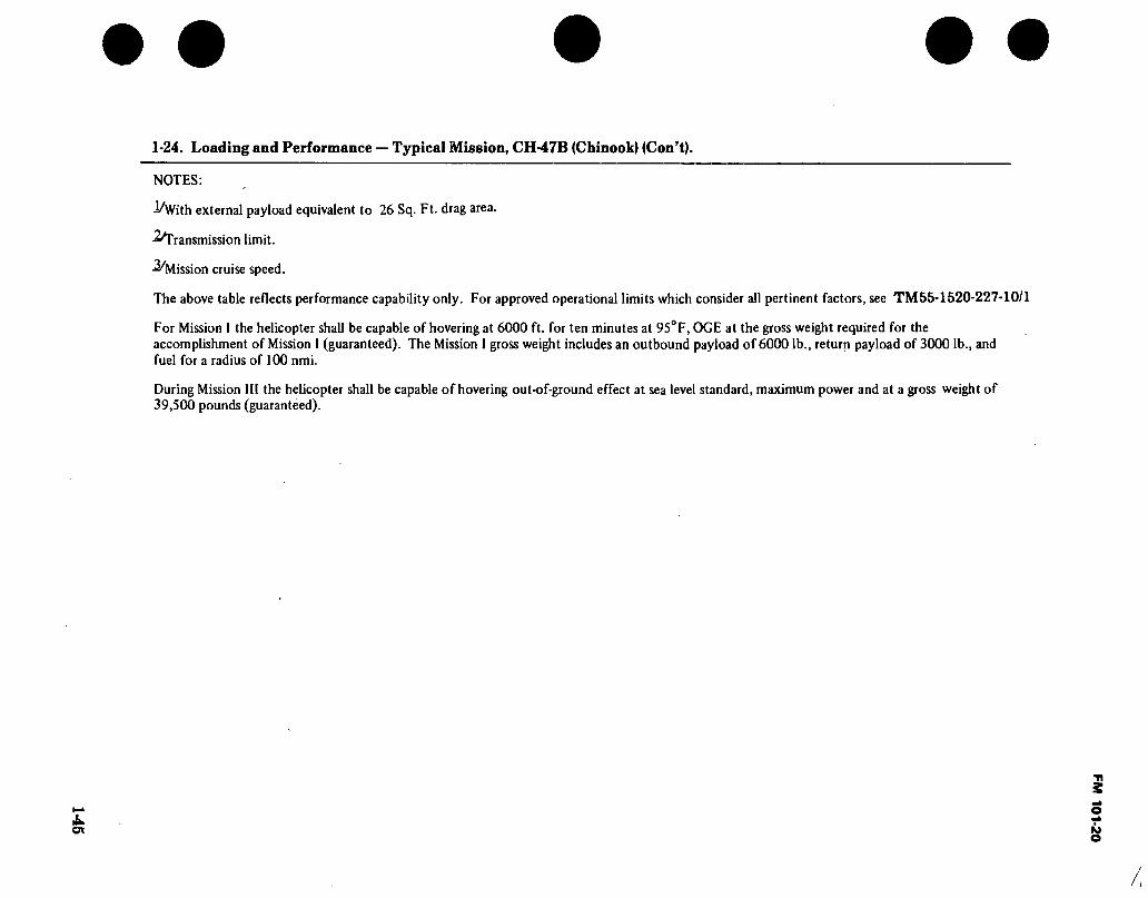
SM
• • • • •
1-24. Loading and Performance — Typical Mission, CH-47B (Chinook) (Con’t).
NOTES:
JAVith external payload equivalent to 26 Sq. Ft. drag area.
■^Transmission limit.
■Scission cruise speed.
The above table reflects performance capability only. For approved operational limits which consider all pertinent factors, see TM55-1520-227-10/1
For Mission I the helicopter shall be capable of hovering at 6000 ft. for ten minutes at 95° F, OGE at the gross weight required for the accomplishment of Mission 1 (guaranteed). The Mission I gross weight includes an outbound payload of 6000 lb., return payload of 3000 lb., and fuel for a radius of 100 nmi.
During Mission III the helicopter shall be capable of hovering out-of-ground effect at sea level standard, maximum power and at a gross weight of 39,500 pounds (guaranteed).
FM 101-20

FM 101-20
1-25. Performance Notes, CH-47B (Chinook).
FORMULA: RADIUS MISSIONS I & II
Warm up, take off, climb on course to 5000 feet at normal power, cruise out at long range speeds to remote base, land, and unload cargo. Without refueling, warm up, take off, climb on course to 5000 feet at normal power, and return at long range speeds. Range- free allowances are 2 minutes of normal power for each warmup and takeoff, plus 10 percent of initial fuel for reserve.
FORMULA: RADIUS MISSION III
Warm up, take off, cruise out at long range speeds at sea level to remote base, land, and unload outbound cargo, load inbound cargo. Without refueling, warm up, take off, return at long range speeds at sea level, land, and unload cargo. Range-free allowances are 2 minutes of normal power for each warmup and takeoff, plus 10 percent of initial fuel for reserve.
FORMULA: RADIUS MISSION IV
Warm up, take off, cruise out at 100 knots at sea level with external cargo to remote base, detach cargo, and land. Without refueling, warm up, take off, and return at long range speeds at sea level. Range-free allowances are 2 minutes of normal power for each warmup and takeoff, plus 10 minutes of cruise fuel for reserve.
FORMULA: RANGE MISSIONS I & II
Warm up, take off, climb on course to 5000 feet at normal power, cruise out at long range speeds until 90 percent of initial fuel is consumed, land, and unload cargo. Range-free allowances are 2 minutes of normal power for warmup and takeoff, plus 10 percent of initial fuel for reserve.
FORMULA: RANGE MISSION III
Warm up, take off, cruise out at long range speeds at sea level until 90 percent of initial fuel is consumed, land, and unload cargo. Range-free allowances are 2 minutes of normal power for warmup and takeoff, plus 10 percent of initial fuel for reserve.
FORMULA: RANGE MISSION IV
Warm up, take off, cruise out at 100 knots at sea level with external cargo until 10 minutes of cruise fuel remains, detach cargo, and land. Range-free allowances are 2 minutes of normal power for warmup and takeoff, plus 10 minutes of cruise fuel for reserve.
FORMULA: RANGE MISSION V
Warm up, take off, climb on course to optimum cruise altitude at cruise speed, cruise out at long range speeds until 90 percent of initial fuel is consumed. Range-free allowances are 2 minutes of normal power for warmup and takeoff, plus 10 percent of initial fuel for reserve.
PERFORMANCE REFERENCES
Vertol Report 114-P-J-602. Detail Specifícations for the Model CH-47B Helicopter.
Boeing-Vertol Report 114-AD-601. Estimated Performance Capability of CH-47B and CH-47C Heli- copters.
Lycoming Model Specification 124.31, T55-L-7C Shaft Turbine Engine.
Source: TSARCOM-DRSTS-WC
1-46

1-47
1-26. CH-47C (Chinook) Characteristics.
ENGINE MISSION AND DESCRIPTION
Mfr’s Model: Vertol The principal mission of the CH47C is to provide air transportation
for troops and cargo. The aircraft can also be utilized for rescue of personnel.
The CH47C is a large tandem rotor helicopter with built-in accommodations for 24 litter patients and 2 attendants or 33 troops and troop commander. The helicopter is equipped with an unobstructed 30-foot long cargo compartment with straight-in rear loading and has a capacity of over 1450 cubic feet. Other features include an external cargo hook of 10-ton capacity and a winch system for loading an auxiliary power unit which powers the utility hydraulic system, thus eliminating the requirements for external ground power sources: stability system provided through Vertol SAS; and provisions for utilizing collapsible fuel tanks to increase the fuel capacity by 2000 gallons. The complete helicopter is designed for operations in temperatures ranging from —25°F to +125°F.
DEVELOPMENT
Date of contract June 1966 Aircraft in production January 1969
CAPACITIES PERSONNEL
No. & model .... (2)T55-L-11D Mfr Lycoming Engine spec No .. 124.54 Engine/Rotor gear
ratio 64.05:1
ENGINE RATINGS
SHP RPM ALT MIN Max ... 3750 16000 SL 10 Mil.... 3750 16000 SL 30 Nor ... 3300 15400 SL Cont
TECHNICAL PUBLICATIONS
AIRFRAME: TM 55-1500-210-MTF TM 55-1500-210-L TM 55-1520-22 7-CL-2 TM 55-1520-227-PM TM 55-1520-227-PMD TM 55-1520-227-PMS TM 55-1520-227-10-2 TM 55-1520-227-23 TM 55-1520-209-23P TM 55-1520-241-S DMWR 55-1500-210
ENGINE: TM 55-2840-234-24/2 TM 55-2840-234-23P TM 55-2840-249-23 DMWR 55-2840-118
Cargo compartment: Floor 228-3/4 sq ft Length 30 ft, 6 in. Width 7 ft, 6.in. Height 6 ft, 6 in. Volume 1487 cu ft Forward door: Height 5 ft, 6 in. Width 3 ft
Crew 4 Troops 33
or
Litters 24
Cargo ramp door: Height 6 ft, 6 in. Width 7 ft, 6 in.
WEIGHTS
LB L.F. Empty M 9,723 Basic M 9,772 Design 33,000 3.00 Combat 323,886 Max alternate
gross wt 46,000 2.15 Normal
takeoff 33,000 Alternate
takeoff 46,000 Max landing 46,000
F or basic mission.
FUEL AND OIL
Fuel: Grade JP4 or JP-5 Spec MIL-T-5624 No. tanks:
Fuselage main. .(2) 620 gal 566 gal (crash resistant)
Fuselage aux... (4) 520 gal 480 gal (crash resistant)
Qty 1141 gal Oil:
Engine contained oil supply Spec
Temps above 25° F MIL-L-23699
Temps below 25° F MIL-L-7808
Qty 7 gal
AVIONICS/ARMAMENT
Refer to chapter 2.
UNIT PRICE/NSN
NSN 1520-00-871-7308 Lin/K30499
UNIT PRICE: Refer to Table 4-1, Page 4-1.
FM101-20

1-48
1-27. Loading and Performance — Typical Mission, CH-47C (Chinook).
CONDITIONS
Gross weight Payload guaranteed (outbound) Payload guaranteed (inbound) Payload estimated (outbound) Payload estimated (inbound)
Vmax at SL/STD, military power .... Max cruise speed at SL/STD normal power
Guaranteed Estimated
V-Cruise (best range) at SL/STD V-Cruise (best range) at 5000 ft/STD . . Rate-of-climb at SL/STD military
power Vertical rate-of-climb at SL/STD maximum
power Service ceiling at normal power Service ceiling, STD temp, single engine
at military power Guaranteed Estimated
Hover ceiling, OGE at STD temperature, max power
Hover ceiling IGE at STD temperature, maximum power, 10 ft. wheel heighf
Radius of action, Guaranteed Estimated
Ferry range
• •
BASIC MISSION
I
BASIC MISSION
(DESIGN GW) II
PRIMARY MISSION
III
EXTERNAL PAYLOAD MISSION
IW
MAXIMUM FERRY
MISSION V
. . .(lb)
. . .(lb)
. . .(lb)
. . .(lb)
. . .(lb)
. . (kn)
. . (kn)
. . (kn)
. . (kn)
. . (kn)
(ft/min)
(ft/min)
• • -(ft)
.(ft)
.(ft)
.(ft)
.(nmi)
.(nmi)
.(nmi)
39,2002/
12,000 6,000
13,300 6,650
1564-/
156*/ 141 136
2,045^
1,2202/ 10,200*/
4,000 4,5002*' 2/
9,600
12,750
100 100
33,000
7,350 3,675
1642/
155 1642/ 140 138
2,8802/
2,5852' 15,000^
9,5502/
14,750
15,000
100
46,000
19,750 9,875
123*/
123*/ 123*/ 111*/
1,3802/
8,000*/
7,600
100
46,000
23,300 0 1005/
100s/ 1005/ loo5/
1,2602/
8,000*/
7,600
20
46,000
123*/
123*/ 123*/ 111*/
1,3802/
8,000*/
7,600
1,226
FM
101-2
0

6M • • • • •
1-27. Loading and Performance — Typical Mission, CH-47C (Chinook) (Con’t).
NOTES:
if With External Payload Equivalent to 26 FT* Drag Area (Troop Seats Incl.) y Hover Gross Weight at 6000 ft/95°F at 245 RPM. y Transmission Limit. y Structural Envelope. y Mission Cruise Speed (Outbound). y Current Hydraulic System Limit. y At 230 RPM. y With 12000 LB Payload.
For Mission I the helicopter shall be capable of hovering at 6000 ft for 10 minutes at 95°F, OGE at gross weight required for accomplishment of Mission I (guaranteed). The Mission I gross weight includes an outbound payload of 12,000 lb., return payload of 6000 lb., and fuel for a radius of 100 nmi.
During Mission III the helicopter shall be capable of hovering out-of-ground effect at SL/STD, maximum power, and a gross weight of 43,000 pounds (guaranteed).
FM 101-20

FM 101-20
1-28. Performance Notes, CH-47C (Chinook).
FORMULA: RADIUS MISSIONS I & II
Warm up, take off, climb on course to 5000 feet at normal power, cruise out at long range speeds to remote base, land, and unload cargo. Without refueling, warm up, take off, climb on course to 5000 feet at normal power, and return at long range speeds. Range- free allowances are 2 minutes of normal power for each warmup and takeoff, plus 10 percent of initial fuel for reserve.
FORMULA: RADIUS MISSION III
Warm up, take off, cruise out at long range speeds at sea level to remote base, land, and unload outbound cargo, load inbound cargo. Without refueling, warm up, take off, return at long range speeds at sea level, land and unload cargo. Range-free allowances are 2 minutes of norma) power for each warmup and takeoff, plus 10 percent of initial fuel for reserve.
FORMULA: RADIUS MISSION IV
Warm up, take off, cruise out at 100 knots at sea level with external cargo to remote base, detach cargo, and land. Without refueling, warm up, take off, and return at long range speeds at sea level. Range-free allowances are 2 minutes of normal power for each warmup and takeoff, plus 10 minutes of cruise fuel for reserve.
FORMULA: RANGE MISSIONS I & II
Warm up, take off, climb on course to 5000 feet at normal power, cruise out at long range speeds until 90 percent of initial fuel is consumed, land, and
unload cargo. Range-free allowances are 2 minutes of normal power for warmup and takeoff, plus 10 percent of initial fuel for reserve.
FORMULA: RANGE MISSION III
Warm up, take off, cruise out at long range speeds at sea level until 90 percent of initial fuel is consumed, land, and unload cargo. Range-free allowances are 2 minutes of normal power for warmup and takeoff, plus 10 percent of initial fuel for reserve.
FORMULA: RANGE MISSION IV
Warm up, take off, cruise out at 100 knots at sea level with external cargo until 10 minutes of cruise fuel remains, detach cargo, and land. Range-free allowances are 2 minutes of normal power for warmup and takeoff, plus 10 minutes of cruise fuel for reserve.
FORMULA: RANGE MISSION V
. Warm up, take off, climb on course to optimum cruise altitude at cruise speed, and cruise out at long range speeds until 90 percent of initial fuel is con- sumed. Range-free allowances are 2 minutes of normal power for warmup and takeoff, plus 10 percent of initial fuel for reserve.
PERFORMANCE REFERENCES
Vertol Report 114-PJ-7003, Detail Specification for The CH-47C Helicopter.
Lycoming Report 124.38,T55-L-11A Engine Speci- fication.
Boeing-Vertol Report 114-AD-601, Estimated Performance Capabilities of CH-47B and CH-47C Heli- copters.
Source: TSARCOM-DRSTS-WC
1-50

FM 101-20
-12 FT. SIN.-
IS FT. 7.6 IN.
|«ll FT. 11 IN.-|
DIMENSIONS
Rotor dia Length:
Rotors operating
Rotors folded Fuselage
Might (overall) Tread Rotor ground clearance:
Static fwd Idling fwd
60 Ft.
98 Ft. 10.7 In. ... 50 Ft. 9 In. ... 50 Ft. 9 In. .. 18 Ft 7.8 In. ..11 Ft. 11 In.
..7 Ft. 6 In. 10 Ft. 10 In.
96 FT. 10.7 IN.
51 FT. 11.4 IN.
60 FT
27 FT. 6 IN.
ROTATION
ROTATION
63 FT. 10 IN.
. 11 1H 38
"*hT IS FT. 11 M. cTZU TURNING it FT. 1 IN
I STATIC O O O O * 10 FT. 11 M. 7 FT. 6 IN. ruKNiMç
STATIC i
(SEE NOTE 2) I 22 FT. 6 m
19.2 IN. MINIMUM OROUND OEARANCE SO FT. 9 IN.
NOTE:
1. THE ABOVE DIMENSIONS ARE BASED ON THE CYCLIC STICK AND DIRECTIONAL PEDALS BEING CENTERED AND THE THRUST CONTROL IN GROUND DETENT.
2. WITH THE FLIGHT CONTROLS OUT OF NEUTRAL, IT IS POSSIBLE FOR THE GROUND TO FORWARD ROTOR BLADE CLEARANCE TO BE 4 FEET 4 INCHES.
3. ALL DIMENSIONS ARE APPROXIMATE. 4. BLADE CHORD IS 32 INCHES.
Figure 1-12. Principal Dimensions, CH-47D (Chinook)
1-51

1-52 1-29. CH-47D (Chinook) Characteristics.
ENGINE MISSION AND DESCRIPTION WEIGHTS
No. and Model (2)T55-L-712 Mfg Lycoming Engine Spec. No 124.53 Type Turboshaft Reduction Great Ratio 66.96 Tail Pipe Augmentation
ENGINE RATINGS
SHP
SEA LEVEL STD Emergency 4500 Maximum 3750 Interme- diate Maximum Continuous 3000 15066 —
RPM
MIN 15066 30 15066 10
The principal mission of the CH-47D is to provide air transportation for troops and cargo. The helicopter can lift 15,000 lbs. of external cargo at 4,000; 95°F, Hoge with a 200 Fpm VROC and transport the load 30 NM.
The CH-47 is a medium lift tandem rotor helicopter powered by 2 turbo shaft engines. The helicopter has a 30 ft long cargo compartment with straight-in rear loading with accomodations for 24 litters and 2 attendants or 33 combat equipped troops and troop commander. The helicopter is designed for operations in temperatures rang- ing from -65° to + 125°F. The YCH-47D has 3 cargo hooks for transportation of loads externally. The center hook has a capacity of 26,000 lbs., 17,000 lbs. for each forward or aft hook and 25,000 lbs. for a single load suspended from the forward and aft hooks. The multi-point (tandem) rigg- ing of external loads improves load stability and increases the allowable cruise speed.
3750 15066 30 DEVELOPMENT
Date of Contact 4 Jun 76 First acft delivered 31 Mar 82
TECHNICAL PUBLICATIONS FEATURES
AIRFRAME: TM 55-1520-240-10 and CL TM 55-1520-240-23 TM55-1520-240-23P TM 55-1520-240-MTF TM 55-1520-240-PM TM 55-1520-240-PMS DMWR 55-1520-241
ENGINE: TM 55-2840-234-23 TM 55-2840-234-23P DMWR 55-2840-254
APU: TM 55-2835-205-23 TM 55-2835-205-23P
Cargo Compartment: Length 30 ft 2 in Width 7 ft 6 in Height 6 ft 6 in
Forward Door: Height 5 ft 6 in Width 3 ft 0 in
Cargo Ramp Door: Height 6 ft 6 in Width 7 ft 7 in
APU: Solar T-62T-2B
Operations: Day, night, VMC, IMC
PERSONNEL
Crew 3 Litters 24 (Plus 2 attendants)
or Troops 33 (Plus troop commander)
LOADING LB. Empty 23,093 Basic — Design 33000 Combat
Clean — Light Scout — Heavy Scout — Hog —
Max. Takeoff 50000 Max. Landing 50000
FUEL AND OIL
Fuel: Grade JP-4 Spec MIL-T-5624 No. tanks 6 Location Fuselage Qty 1034 Gal
Oil: (Engine) Spec ... MIL-L-23699/7808 No. tanks... 1/Eng Location Internal Qty 3.75 Galea
AVIONICS/ARMAMENT
Refer to Chapter 2.
UNIT PRICE/NSN
NSN 1520-01-088-3669 UNIT PRICE: Refer to Table 4-1.
FM
101-20

1-53
1-30. Loading and Performance — Typical Missions, CH-47D (Chinook).
CONDITIONS MISSION
I (ROC)
MISSION 112/
MISSION 1112/
MISSION IV4/
FERRY MISSION
\hJ MISSION
Vlfi/ DES GW
(33000 LB
Estimated Mission Maximum gross weight (GW) (lb) Payload guaranteed (outbound external) (lb) Payload guaranteed (inbound external) (lb) Payload estimated (outbound) (lb) Payload estimated (inbound) (lb) V max at SL/STD, Intermediate power (kn) Max cruise speed at SL/STD, Maximum continuous power,
Guaranteed (kn) Actual (kn)
Ave V-Cruise (outbound) (kn) Ave V-Cruise (inbound) (kn) Max rate-of-climb at Mission Max GW (Intermediate
power) (ft/min) Vertical rate-of-climb at Mission Max GW,
Take off horsepower (ft/min) Service ceiling at maximum continuous power (ft) Service ceiling, single engine at emergency power
Guaranteed (ft) Actual (ft)
Hover ceiling, OGE at STD temperature Take off horsepower (ft)
Hover ceiling, IGE at STD temperature Take off horsepower, 10 ft wheel height (ft)
Radius of action Guaranteed (nmi) Estimates (nmi)
Ferry range (nmi)
42900 15000
15800
101 140 798
200
30 30
50000
22630
44000 13000
14300 7150
126 135
1487
890
121 140 668
30 100
42440
15300
50000 49991
23854
97 140 843
200
138
1470
970
136 122
1431
1065
30 1090 20
167
155 158
3750 (SL)
4200 (SL)
15000 10000 13100
15000
15000
FM
101-20

FM 101-20
1-30. Loading and Performance — Typical Missions, CH-47D (Chinook) (Con’t).
NOTES:
jy Ambient Conditions: 4000 ft/95°F. External load provides a drag area of 50 sq ft and download of 0.8% GW. This is a Required Operational Capability (ROC) Mission.
2/ Ambient Conditions: SL/STD. External load provides a drag area of 50 sq ft and download of 0.8% GW.
ZJ Ambient Conditions: 4000 ft/95°F.
¿J Ambient Conditions: 4000 ft/95°F. External load provides a drag area of 75 sq ft and download of 1.87% GW.
sy Ambient Conditions: Standard atmosphere. Additional ferry fuel is carried in 5 internally mounted aux- iliary 600 gal tanks.
.6/ Self Retrieval. Ambient Conditions: SL/STD. Retrieval weight is 23,854 lbs. External load provides a drag area of 700 sq ft and download of 5.0% GW.
Reference: Boeing Vertol Report 145-PJ-8103-1, Prime Item Development Specifications for the Model CH-47D Helicopter.
1-54

FM 101-20
1-31. Performance Notes, YCH-47D (Chinook).
Formula Radius Mission I, II and IV — Warm up, take-off, hover, acquire external load, climb vertically at maximum power and cruise outbound at long range speed to drop zone. Hover at drop zone to unload cargo and cruise inbound at long range speed. Range free allowances are 2 minutes of maximum continuous power for warm up and take-off, 2 minutes total hover-out-of- ground-effect, 1 minute vertical climb (200 fpm) and 30 minutes reserve at long range cruise speed. This is the Required Operational Capability (ROC) mission profile.
Formula: Radius Mission III — Load cargo internally, warm up, take-off, hover-out-of-ground-effect and cruise outbound to landing zone at long range speed. Land and exchange cargo (inbound load equals 1/2 outbound load), warm up, take-off, hover-out-of-ground effect and cruise inbound at long range speed. Range free allowances are 2 minutes of maximum continuous power for each warm up, take-off and hover plus 30 minutes reserve at long range cruise speed.
Formula: Ferry Mission V — Warm up and take-off at sea level and cruise climb to 8000 ft. Cruise at 8000 ft at long range speed to landing zone. Range free allowances are warm up and take-off, 2 minutes at maximum continuous power and a reserve of 10% of initial fuel.
Formula: Self Retrieval Mission VI — Warm up, take-off, climb vertically for 1 minute and cruise outbound with no load. Hover OGE for 1 minute at pickup zone, pickup load, climb vertically for 1 minute at 200 fpm, cruise inbound with load, hover OGE for 1 minute, deposit load and land with 15 minutes fuel reserve at 99% best range airspeed. Sortie radius is 20 NM.
Source: AVRADCOM-DRCPM-CH47M-T
1-55

FM 101-20 "b D
f
Figure 1-13. CH-54A and B (Tarhe), Typical (minor differences apparent between A and B models)
1-56

/U 0 s~~ FM 101-20
25 FT 5 IN. ©H®
□ 19 FT 9 IN
DIMENSIONS
Main rotor dia ’’S Ft. Length (rotors
operating) 88 Ft. 5 In. Length (fuselage) 70 Ft. 3 In. Height (static) 26 Ft. 5 In. Width (cockpit) 7 Ft. 1 In. Tread 19 Ft. 9 In. Gnd clearance:
Main rotor (idling) 16 Ft. 8 In. Tail rotor 9’4”
3 FT 10» IN.
88 FT 6 IN.
72 FT
O
16 FT 8 IN (IDLING)
16 FT
9 FT 4 IN
1
70 FT 3 IN.
Figure 1-14. Principal Dimensions, CH-54A (Tarhe)
1-57

1-58
1-32. CH-54A (Tarhe) Characteristics.
ENGINE
No. & model... .(2) T73-P-1 Mfr Pratt & Whitney Spec 2453 Type Axial Weight 9251b
ENGINE RATINGS
T73-P-1 SHP RPM MIN
MUitary ...4500 9000 30 Normal
rated 4000 9000 Cont.
TECHNICAL PUBLICATION
AIRFRAME: TM 55-1520-217-MTF-l TM 55-1520-217-L TM 55-1520-217-S TM 55-1520-217-CL-l TM 55-1520-217-10-1 TM 55-520-217-23-1 TM 55-1520-217-23P TM 55-1520-217-PMS TM 55-1520-217-PMS-l
ENGINE: TM 55-2840-230-23 TM 55-2840-230-23P TM 55-2840-230-24
AUXILIARY POWER UNIT: TM 55-2835-203-24 TM 55-2835-203-23P DMWR 55-2835-100
MISSION AND DESCRIPTION
Mfr’s Model: Sikorsky S-64E Missions that may be accomplished with the CH-54A helicopter
include: movement of heavy outsized loads, towing of surface vehicles, recovery of downed aircraft, and by use of detachable pods, transporta- tion of personnel, vehicles, and equipment (including Paratroop lOperations). | Since cargo is canied externally byanoist, the ground icrew may load or unload cargo while the helicopter hovers overhead, thereby extending the operational capability into areas unsuitable for landing. Flattopped fuselage serves as a work platform for servicing engines, rotor systems, and main components.
This helicopter is of the all-metal, single main rotor type with one anti-torque tail rotor. The two gas turbine engines are located above the fuselage. The wheel-type alighting gear consists of two fixed main gear assemblies and a fixed nose gear assembly. The enclosed cockpit forming the nose of the helicopter carries basic accommodations for pilot, copilot, and an aft facing pilot. Conventional helicopter flight controls are provided for forward facing pilot seats. Automatic stabilization equipment is also provided. The aft facing pilot seat has cyclic and directional trim controls and a conventional collective pitch stick. Cargo handling provisions include a hydraulic powered hoist. Space and structural provisions are also made for a cargo sling or towing assembly.
DEVELOPMENT
First production acft delivered Nov 66 Production status out of production
FEATURES
Six-blade main rotor. Rear facing seat for aft pilot/hoist operator
A four-point 20,000 lb capacity load suspension system and a 20,000 lb capacity single point cargo hoist.
Four-blade, anti-torque tail rotor.
PERSONNEL
Crew (normal) 3 Pilot 1 Copilot 1 Aft pilot 1 Observers 2
Passengers (with Pod Attached) Troops 45
or Utters 24 and Attendants 3
WEIGHTS
LB L.F. Empty 19,219 Basic 21,361 Gross
(design)... 38,000 2.50 (alternate).. 42,000 2.26
FUEL AND OIL
Fuel: Grade JP4 0r -5 Spec MIL-T-5624
Q‘y 1342 (8723 lb. JP-4)
Oil: Spec MIL-L-23699 Qty 1.73 gal
AVIONICS/ARMAMENT
t/ 0
Refer to chapter 2.
UNIT PRICE/NSN
CH-54A, NSN 1520-00-964-9601 Line K30515,
UNIT PRICE: Refer to Table 4-1
FM
101-20
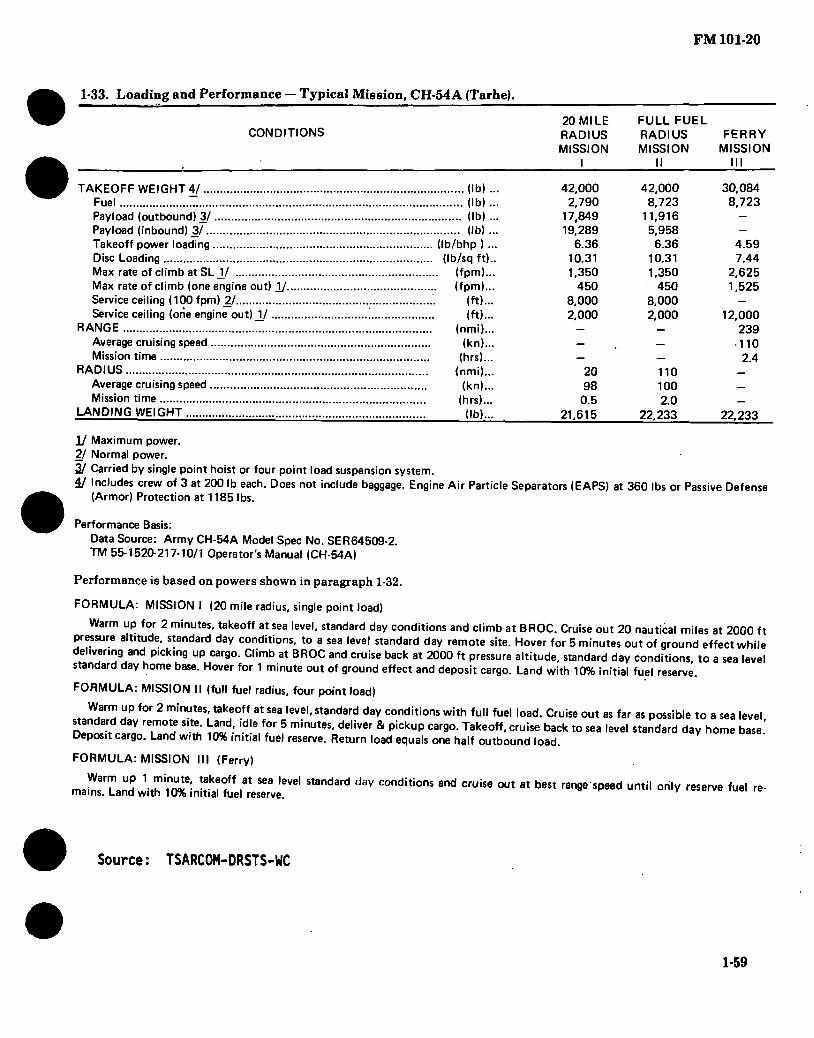
FM 101-20
1-33. Loading and Performance — Typical Mission, CH-54A (Tarhe).
CONDITIONS 20 MILE RADIUS MISSION
I
FULL FUEL RADIUS MISSION
FERRY MISSION
III
TAKEOFF WEIGHT 4/ (lb) ... Fuel (lb) ... Payload (outbound) 3/ (lb) ... Payload (inbound) 3/ (lb) ... Takeoff power loading (Ib/bhp ) ... Disc Loading (Ib/sq ft).. Max rate of climb at SLJ/ (fpm)... Max rate of climb (one engine out) 1/ (fpm)... Service ceiling (100 fpm) 2/ Service ceiling (one engine out) J/ .
RANGE Average cruising speed Mission time
RADIUS Average cruising speed Mission time
LANDING WEIGHT
(ft)... (ft)...
(nmi)... (kn)...
(hrs)... (nmi)...
(kn)... (hrs)...
(lb).,.
42,000 2,790
17,849 19,289
6.36 10.31 1,350
450 8,000 2,000
20 98 0.5
21,615
42,000 8,723
11,916 5,958 6.36
10.31 1,350
450 8,000 2,000
110 100 2.0
22,233
30,084 8,723
4.59 7.44
2,625 1,525
12,000 239 110 2.4
22,233
1/ Maximum power. 2/ Normal power. 3/ Carried by single point hoist or four point load suspension system. 4/ Includes crew of 3 at 200 lb each. Does not include baggage. Engine Air Particle Separators (EAPS) at 360 lbs or Passive Defense
(Armor) Protection at 1185 lbs.
Performance Basis: Data Source: Army CH-54A Model Spec No. SER64509-2. TM 55-1520-217-10/1 Operator's Manual (CH-54A)
Performance is based on powers shown in paragraph 1-32.
FORMULA: MISSION I (20 mile radius, single point load)
Warm up for 2 minutes, takeoff at sea level, standard day conditions and climb at BROC. Cruise out 20 nautical miles at 2000 ft pressure altitude, standard day conditions, to a sea level standard day remote site. Hover for 5 minutes out of ground effect while delivering and poking up cargo. Climb at BROC and cruise back at 2000 ft pressure altitude, standard day conditions, to a sea level standard day home base. Hover for 1 minute out of ground effect and deposit cargo. Land with 10% initial fuel reserve.
FORMULA: MISSION II (full fuel radius, four point load)
Warm up for 2 minutes, takeoff at sea level, standard day conditions with full fuel load. Cruise out as far as possible to a sea level
. v T0!fSlt!; ^d' ldle,f?r 5 minutes' deliver & P¡ckuP car9°- Takeoff, cruise back to sea level standard day home base.' Deposit cargo. Land with 10% initial fuel reserve. Return load equals one half outbound load.
FORMULA: MISSION III (Ferry)
ma"TanUdP Jith imlmaîte.^s“rvéeVe, ** C°"dÍtÍOnS ^ CrUiS6 °Ut “ ^ ^ Unti' °ri,V reServe fuel re'
Source: TSARCOM-DRSTS-WC
1-59

FM 101-20
DIMENSIONS
-21 FT 10 IN
© ©
X_D □ > <
—-17 FT 7 INK-
-19 FT 9 IN.—
Main rotor dia 72 Ft. 3 In. Length:
Rotors operating 88 Ft. 6 In.
Fuselage 70 Ft. 3 In. Height (static) 25 Ft. 4 In. Width (cockpit) 7 Ft. 1 In. Tread .'. 21 Ft. 10 In. Gnd clearance:
Main rotor (idling) 15 Ft. 8 In. Tail rotor ■ 9 Ft. 4 In.
3 FT 10-1/2 IN
o
88 FT 6 IN.
72 FT 2 IN.
FT IN
FT IN
STATIC DROP
CLEARANCE AT GROSS WEIGHT 9 FT 3 IN. t
/ 6 FT 6 IN 2 FT 6 IN
13FT6IN
<<^ 25 FT 4 IN. y/
RETRACTED
9 FT 4 IN.
IN. I EXTENDED | 9FT4[I
Figure 1-15. Principal Dimensions, CH-54B (Tarhe)
1-60

19*1
1-34. CH-54B (Tarhe) Characteristics.
ENGINE MISSION AND DESCRIPTION WEIGHTS
No. & model (2)T73-P-700 Mfr Pratt & Whitney Spec 2456 Type Axial Weight 935 lbs
ENGINE RATINGS
SHP Military 4800 Normal
rated 4430
RPM MIN 9000 30
9000 Cont,
TECHNICAL PUBLICATION
AIRFRAME: TM 55-1520-217-MTF TM 55-1520-217-MTF-2 TM 55-1520-217-L TM 55-1520-217-S TM 55-1520-217-CL-2 TM 55-1520-217-10-2 TM 55-520-217-23-2 TM 55-1520-217-23P TM 55-1520-217-PMS TM 55-1520-217-PMS-2
Mfr’s Model: Sikorsky S-64F
Missions that may be accomplished with the CH-54B helicopter include: movement of heavy outside loads, towing of surface vehicles, recovery of downed aircraft, and by use of detachable pods, transportation of personnel, ve- hicles, and equipment (including para troop operations). Since cargo is carried externally by a hoist, the ground crew may load or unload cargo while the heli- copter hovers overhead, thereby extending operational capability into areas un- suitable for landing. The flat top of the fuselage serves as a work platform for maintenance and servicing of the engines, rotor systems and other components of the power train system.
The CH-54B is an all-metal single, main rotor type helicopter with one anti- torque tail rotor. It is powered by two gas turbine engines located above the fu- selage. The wheel type landing gear consists of two fixed main gear assemblies and single fixed, fully swiveling nose gear assembly. The fuselage and landing gear are constructed and assembled in a crane configuration. The enclosed cockpit forming the nose of the aircraft has basic accommodations for pilot, co- pilot, aft-facing pilot and two observers. Conventional helicopter flight controls are provided for the pilot and co-pilot. The aft-facing pilot has electrically oper- ated cyclic and directional trim controls and a conventional collective pitch control. An automatic flight control system (AFCS) is also provided. Cargo han- dling capabilities consist of a removable single point hydraulic powered four point load suspension system. Provisions are also made for installation of a tow- ing kit.
LB L.F. Empty 19,864 Basic 22,386 Gross (Design).. 47,000 2.0
FUEL AND OIL (USABLE)
Fuel: Grade JP-4 or -5 Spec MIL-T-5624 Q‘y 1342
(8723 lb. JP-4)
Oil: Spec MIL-L-23699 Qty 1.73 gal
AVIONICS/ARMAMENT
DEVELOPMENT
First flight First production aircraft delivered Production status
June 1969 Dec 1969 Out of production
Refer to chapter 2.
UNIT PRICE/NSN
ENGINE: TM 55-2840-230-23 TM 55-2840-230-23P TM 55-2840-230-24
AUXILIARY POWER UNIT: TM 55-2835-203-24 TM 55-2835-203-23P DMWR 55-2835-100
FEATURES
Six-blade main rotor. Aft-facing pilot/hoist operator. 25.000 lb. capacity four point
load suspension system. 25.000 lb. capacity single
point hoist. Four-blade anti-torque tail rotor.
PERSONNEL
Crew (normal) 3 Pilot 1 Co-pilot 1 Aft-pilot 1
Observers 2 Passengers (with pod attached)
Troops 45 Litters 24 Attendants 3
CH-54B, NSN 1520-00-113-5776 Line K30515, UNIT PRICE: Refer to Table 4-1.
Xf e)
FM
101-20

FM 101-20 /U &, 'bD
1-35. Loading and Performance — Typical Mission, CH-54B (Tarhe).
20 MILE RADIUS MISSION
I
FULL FUEL RADIUS MISSION
II
TAKEOFF WEIGHT 5/ (Ib) ... Fuel (Ib) ... Payload (outbound) J/ (Ib) ... Payload (inbound) 3/ (lb) ... Takeoff power loading (lb/bhp)... Disc Loading (Ib/sq ft) ... Max rate of climb at SL 1/ (fpm) ... Max rate of climb (one engine out) 1/ (fpm) ... Service ceiling (100 fpm) 2/ (ft) ... Service ceiling (one eninge out) 1/ (ft) ;..
RANGE 4/ (nmi) ... Average cruising speed (kn) ... Mission time (hrs)
RADIUS 4/ Z”‘(nmi) . Average cruising speed (kn)... Mission time (hrs) ...
LANDING WEIGHT (lb) ...
47.000 2,906
21,708 23,220
5.95 11.50 1,350
490 10.000 2,000
20 103 0.5
22,650
47.000 8,723
15,891 7,946
5.95 11.50 1,350
490 10.000 2,000
101 100 2.0
21,514
FERRY MISSION
III
31,109 8,723
3.79 7.36
2,915 1,890
12,000 226 100 2.3
23,258
1/ Maximum power. 2/ Normal power. 3/ Carried by single point hoist or four point load suspension system. 4/ Detailed descriptions of missions are given in paragraph 1-33. 5/ Includes crew of 3 at 200 lb each. Does not include baggage, Engine Air Particle Separators (EAPS) at 360
lbs or Passive Defense (Armor) Protection at 1285 lbs.
Performance Basis: Data Source: Army CH-54B Model Spec No. SER64279.
TM 55-1520-217-10/2 Operator's Manual (CH-54B)
Performance is based on powers shown in paragraph 1-34.
Source: TSARCOM-DRSTS-WC
1-62

FM 101-20
T)V
Figure 1-16. CH-54A and B (Tarhe), Typical, with Universal Military Pod
&
8»
0 O
((%
(J o (&J
DIMENSIONS
Length 28 Ft. 1 In. Width 9 Ft. 6 In. Height (Wheels up) 7 Ft. 8 In. Weight:
Empty 3020 pounds Max Load 20,000 pounds
Figure 1-17. Universal Military Pod
1-63

FM W¡1-2<D)
1-36. Universal Military Pod, CH-54A and B (Tarlbe).
The universal military pod is a semimonocoque structure with a rear loading split door-ramp extending the full width and height of the pod. The split-door construction permits both sides to be opened independently, and reduces the proba- bility of jamming. This arrangement permits easier exit in case of an emergency. Two forward doors, one on each side of the pod, are jettisonable and can be opened from both inside and outside. Each door has a secure locking device to prevent inadvertent opening in flight. Four windows, two on each side, are installed using a rubber push-out type seal and can be removed from both the inside and outside of the pod. A nonstructural panel with a push-out type window is in the forward bulk-head. The window is removable from inside the pod. Additional design features follow:
&• Floor loading is 334 pounds per square foot at any location. In the vehicular tread area the maximum allowable floor loading is 1500 Ibs/sq. ft. The floor is reinforced to accommodate equip- ment as heavy as a 155 Howitzer. Cargo fittings are flush with the floor and have a load capacity of 5000 pounds each. The spacing of the fittings is a standard 20-inch grid pattern.
b. Pod is attached to helicopter load leveler sys- tem. Two rubber strips are attached to the top of the pod, running full width, to prevent chafing be- tween the top of the pod and the bottom of the helicopter. When the pod carries troops (passen- gers) or litter patients, safety provisions require the insertion of screw actuated pins in the pri- mary adapter fittings. This will prevent jettison- ing of the load. The primary missions for the pod are to carry a maximum of 45 troops (passengers) or 24 litter patients and to transport general cargo such as missiles, vehicles, weapons, and general supplies.
c. Pod has a conventional four wheel system with pneumatic tires and may be towed at speeds up to 5 miles per hour on level ground at the maximum gross weight of 20,000 pounds. Each of the four wheels has an independent retraction and extension system manually-operated by the mechanical jacks or alternate hydraulic pumps attached to each wheel gear. These permit the pod to be raised or lowered when fully loaded. This action aids unloading the pod by allowing the use of a fork lift and other cargo moving equipment. To obtain the maximum pod wheel ground clear-
ance of 18 inches, when the pod is attached to the helicopter, full retraction of the pod wheels is possible. Detachment from the helicopter without using winches is made by extending the wheel mechanism.
d. Electrical power is supplied to pod by the helicopter’s electrical system. When the pod is attached to the helicopter, two cables on the front exterior bulk-head of the pod are attached to the ac and dc recentacles on the left side external skin of the helicopter, marked POD PWR AC, DC, ICS. When the pod is not attached to the helicopter, electrical power is supplied from a ground source through cables to the ac and dc receptacles marked EXT POWER 115 VOLTS AC and EXT POWER 28 VOLTS DC, on the left side of the pod.
e. Lighting for the interior of the pod consists of twelve light assemblies, arranged in parallel lines of six lights each on the ceiling. The forward two lights near the entrance doors are white or red controlled by a switch marked ENTRANCE LIGHTS WHITE AND RED. The eight interior lights are controlled by a switch marked INTER- IOR.LIGHTS, ON-OFF. Both switches are on the master switch panel on the left forward wall of the pod. The last two lights at the ramp end of the pod are controlled by a switch at the rear on the left wall marked CARGO LOADING LIGHTS, ON-OFF. Communication between the pod and the helicopter is through a third cable, in the same area as the electrical power cables. The cable is attached to the ICS outlet on the helicopter and is routed to the interphone control panel for the pod, which is on the forward ceiling. Also in this area is a stowage rack for the 30-foot cable.
f. Electrically-operated ventilating blower with a capacity of 500 cfm is installed on the forward bulk head of the pod and is controlled by a switch marked VENT BLOWER, ON-OFF on the master switch panel. Two exhaust openings are on the right and left sides of the pod in the rear area.
Source: TSARCOM-DRSTS-WC
1-64

FM 101-20
biiiiii r
4 FT 6 13/16 IN.-
8 FT 6 IN
8 FT 1 1/2 IN. P
O
DIMENSIONS
Rotor dia 26 Ft. 4 In. Length:
Rotor operating 30 Ft. 3-3/4 In.
Rotor folded 22 Ft. 9-1/2 In. Height 8 Ft. 6 In. Tread 6 Ft. 9-1/4 In.
6 FT 9 1/4 IN. <-4
£3
¿1 TL
-J4FT31N.I— DIAMETER
-26 FT 4 IN. DIAMETER
30 FT 3 3/34 IN
œ
Q
t
m Figure 1-18. Principal Dimensions, OH-6A (Cayuse)
1-65

1-66 1-37. 0H-6A (Cayuse) Characteristics.
ENGINE No. & model .. (1) T63-A-5A/700 Mfr Detroit Diesel
Allison Div of CMC
Engine spec No. T63-A-5A 58ÖJ, dtd
30 Sept 1970 T63-A-700 803F, dtd
30 Sept 1970 Amend 1.
MISSION AND DESCRIPTION WEIGHTS
ENGINE RATINGS
Output Ratings SHP
Takeoff &mU *317 Normal **270
Output speed SFC lb/
SHP- rpm HR
Takeoff & mil .... 6000 0.697 Normal 6000 0.706
Above ratings developed on standard sea level static conditions. ♦Derated to 252.5 for 5 min
♦♦Derated to 214.5
TECHNICAL PUBLICATIONS
AIRFRAME: TM 55-1520-214-10 TM 55-1520-214-CL TM 55-1520-214-MTF TM 55-1520-214-PMS TM 55-1520-214-ESC TM 55-1520-214-23 TM 55-1520-214-23P TM 55-1520-214-S DMWR 55-1520-214
ENGINE: TM 55-2840-231-24 TM 55-2840-231-23 TM 55-2840-231-23P
MFR’s Model: Hughes 500
The principal missions of the OH-6A light obeservation helicopter are visual observation and target acquisition, NOE flight, reconnaissance, and command control. This helicopter is employed in support of combat companies, and will operate for extended periods of time with only such support as provided by one mechanic with handtools. Normal operation is limited to day or night visual flight conditions.
The light observation helicopter is a single-lifting, 4-blade rotor, 4-place helicopter with a gross weight of 2550 lb or less. It is powered by a T63-A-5A/700 free turbine engine with 317 SHP, derated to 252.5 SHP. It incorporates dual flight controls with the secondary cyclic control element easily removable. The flight in- struments are limited to those required for day and night marginal visual conditions. The cargo area contains troop-type seats which are easily stowable when not in use.
DEVELOPMENT
Design competition initiated . Flight evaluation completed Production contract First production acft deliveries
October 1960 June 1964 May 1965 September 1966
FEATURES
Dual controls. Stowable troop seats.
PERSONNEL
Crew (normal) Observer Copilot
Empty Useful load Pilot Observers (2),
Copilot (1) Cargo Fuel Gross (FAA certified) Max structure
.1158
.1242
. 200
. 600
. 42
. 400
.2550
.2700
FUEL AND OIL
Fuel: Grade JP-4 Spec MIL-T-5624 Alternate ... JP-5, MIL-T-5624 Qty 61.3 gal(non-crash
resistant) 54.4 gal (crash resistant)
OU: Spec MIL-L-23699 Alternate ... MIL-L-7808 No. tanks .. 1 Location ... Engine section Qty 3 qt
Main Transmission: Spec MILL-23699 Alternate ... MILL7808 Qty 8.0 pt
Tail Rotor Transmission: Spec MILL-23699 Alternate ... MILL-7808 Qty 0.5 pt
AVIONICS/ARMAMENT
Refer to chapter 2.
UNIT PRICE/NSN
NSN 1520-00-918-1523 Lin K30645
UNIT PRICE: Refer to Table 4-1.
\f
• • • • • F
M 101-20

1-67
y
1-38.
• • • • Loading and Performance — Typical Mission, OH-6A (Cyuse).
BASIC MISSION
I
ALTERNATE 1A (CLEAN)
II
ALTERNATE 1A (ARMED)
III
FERRY RANGE
IV
HIGH SPEED SEA LEVEL MISSION
V TAKEOFF WEIGHT (Ib)
Fuel (lb) Payload (not including pilot) (lb) Takeoff power loading (lb/bhp) Disk loading (Ib/sq ft) Speed for Min. R/D (knots) Max rate of climb at sea level 1/ (fpm) Speed for max R/C, sea level U (knots) Time: Sea level to 5000 ft (minutes). Time: Sea level to 10,000 ft-1/ (minutes). Service ceiling (100 fpm)-^ (ft).. Absolute hover ceiling -V (ft).. COMBAT RANGE (nmi) ..
Average craising speed Jl fjj (knots) .. Cruising altitude (ft).. Total mission time (hr)..
COMBAT RADIUS (nmi).. Average cruising speed J/ñ/ (knots) .. Cruising altitude (ft) .. Mission time (hr) ..
COMBAT WEIGHT ^ (lb) .. COMBAT ALTITUDE (ft)..
Combat speed (knots).. Combat climb (fpm) .. Service ceiling-2/ (ft).. Absolute hover ceiling -1/ .• (ft) .. Max rate of climb @ sea level ^ (fpm).. Speed for max R¿C, sea level (knots) .. Maximum speed 1/è/ (knots) .. Basic speed at 5000 ft (knots) ..
LIMIT FLIGHT LOAD FACTORS Maneuver Positive (g) • ■ Maneuver Negative (g) • •
2159 400 400
8.55 3.96 54.0 1925 56.0
2.5 5.3
18.400 11,200
370 104
12,200 3.6 185 104
12,200 3.6
1961 12,200
116 1860
20,950 14.400
2250 55
104 117
,2.82 0.50
2550 400 637 4/
9.50 4.41 54.0 1560 58.0
3.3 7.0
15.850 6,500
330 102
9600 3.3 165 102
9600 3.3
2207 9600
112 1680
17.850 10,500
1860 56
102 113
2.54 0.50
2550 400 400 9.50 4.41 54.0 1560 58.0
3.3 7.0
15.850 6,500
316 100
9500 3.2 158 100
9500 3.2
2208 9500
112 1680
17.850 10, 500
1860 56 100 110
2.54 0.50
5/ 2159 400 400
8.55 3.96 54.0 1925 56.0
2.5 5.3
18,400 11,200
294 130 SL 2.3 147 130 SL 2.3
1977 SL
130 2220
20,750 14,100
2220 55
130
2.82 0.50
-^Takeoff power up to 5 minutes. ^Normal power. ^For RADIUS mission, includes copilot at 200 lbs.
FM
101-20

1-68
1-38. Loading and Performance — Typical Mission, OH-6A (Cayuse) (CONT).
SJ See Para 1-35.
^/includes. M-27 or M-27E-1 Armament Kit. ULimited by Vne. J/At combat altitude and combat weight.
Performance Basis:
a. Army flight test YOH-6A.
b. All performance is out of ground effect and for standard atmospheric conditions. Speeds given are true airspeed.
• • • • •
FM
101-20

FM 101-20 'T>°
1-39. Performance Notes, OH-6A (Cayuse).
FORMULA: RADIUS MISSION I, II, & III
Warm up, take off, climb on course at military power to altitude for best range at average cruise weight. Cruise to remote base at speed for best range. Do not land. Return to home base. Range-free allow- ances are 2 minutes of normal power for warmup and 10 percent of initial fuel for reserves.
FORMULA: RANGE MISSION I, II, & III
Warm up, take off, and climb on course at mili- tary power to altitude for best range at average cruise weight. Cruise to remote base at speed for best range. Range-free allowances are 2 minutes of normal power for warmup and 10 percent of initial fuel for reserve.
FORMULA: FERRY RANGE MISSION IV
Warm up, take off, and climb on course at mili- tary power to 5,000 feet. At steady cruise, climb to stay at optimum altitude as weight decreases. Range- free allowance is 2 minutes of normal power for warmup. No reserve fuel allowance.
FORMULA: RADIUS MISSION V
Warm up, take off, and accelerate to maximum speed. Cruise at sea level at maximum speed, as limited by normal power or Vne to remote base. Do not land. Return to home base. Range-free allowances are 2 minutes of normal power for warmup and 10 percent of initial fuel for reserve.
FORMULA: RANGE MISSION V
Warm up, take off, and accelerate, to maximum speed. Cruise at sea level at maximum speed, as limited by normal rated power Vne to remote base. Range-free allowances are 2 minutes of normal power for warmup and 10 percent of initial fuel for reserve.
GENERAL DATA
For detailed planning refer to applicable technical manual.
PERFORMANCE REFERENCE
Hughes Tool Company-Standard Aircraft Char- acteristics (OH-6A).
*
s. wm
Figure 1-19. OH-6A (Cayuse)
Source: TSARCOM-DRSTS-WO
1-69

Figure 1-20. OH-58A and C Light Observation Helicopter (Kiowa), Typical
1-70

FM 101-20
DIMENSIONS
Rotor dia 35 Ft .4 In. Length:
Rotors operating 40 Ft. 11.8 In.
Blades removed 32 Ft. 2.0 In.
Height: To top of
rotor 9 Ft. 7.0 In. Tread of skids 6 Ft. 5.4 In. Main rotor:
Disk area 979.8 Sq. Ft. Blade area 38.26 Sq. Ft.
Tail rotor: Disk area 20.97 Sq. Ft. Blade area 2.26 Sq. Ft.
(5)
© ax
Ü//I3 © ¡c_y (3/ ü
I® Sa
® ^ ©-1
©
9
Figure 1-21. Principal Dimensions, OH-58A (Kiowa) (Sheet 1 of 2)
1-71

FM 101-20
HEIGHT
1. Forward Tip of Main Rotor (Static Position) to Ground with Droop
2. Forward Tip of Main Rotor to Ground (Tie-down)
3. Forward Tip of Main Rotor to Ground (Forward Down)
4. Ground to Top of Main Rotor Reservoirs
5. Bottom of Cabin* 6. Top of Vertical Stabilizer 7. Tail Skid to Ground
WIDTH
8.
9.
10.
11.
12.
13.
14.
15. 16.
17.
18.
Skid Gear Horizontal Stabilizer.
DIAMETERS
Main Rotor Tail Rotor
LENGTH
Overall (Main Rotor Fore and Aft) to Aft End of Tail Skid Nose of Cabin to Aft End of Tail Skid Nose of Cabin to Center Line of Main Rotor Skid Gear Nose of Cabin to Center Line of Forward Cross Tube Nose of Cabin to Center Line of Aft Cross Tube Pitot Tube
STANDARD SKID GEAR
9 Ft. 6.0 In.
12 Ft. 0.0 In.
6 Ft. 8.0 In.
9 Ft. 7.0 In. 13.0 In.
8 Ft. 1.5 In. 1 Ft. 4.4 In.
6 Ft. 5.4 In. 6 Ft. 3.2 In.
35 Ft. 4.0 In. 5 Ft. 2.0 In.
40 Ft. 11.8 In.
32 Ft. 2.0 In.
8 Ft. 10.1 In. 8 Ft. 1.3 In.
6 Ft. 0.0 In.
10 Ft. 9.0 In. 6.8 In.
HIGH SKID GEAR
10 Ft. 0.0 In.
12 Ft. 6.0 In.
7 Ft. 2.0 In.
10 Ft. 9.0 In. 27.0 In.
10 Ft. 1.5 In. 3 Ft. 4.4 In.
7 Ft. 3.0 In. No Change
No Change No Change
No Change
No Change
No Change 10 Ft. 4.2 In.
5 Ft. 9.4 In.
10 Ft. 6.3 In. No Change
*Check antennas that may protrude lower.
Figure 1-21. Principal Dimensions (Sheet 2 of 2)
FLOAT GEAR
9 Ft. 7.9 In.
12 Ft. 1.9 In.
6 Ft. 10 In.
10 Ft. 5.4 In. 28 In.
11 Ft. 1.0 In. 4 Ft. 4.0 In.
11 Ft. 6.1 In. No Change
No Change No Change
No Change
No Change
No Change 19 Ft. 5.0 In.
5 Ft. 11.7 In.
10 Ft. 8.7 In. No Change
1-72

1-73 • • • • •
1-40. OH-58A (Kiowa) Characteristics
ENGINE MISSION AND DESCRIPTION
No. & model .. Mfr Engine spec. no.
Type
Length .... Width Height Weight .... Helicopter rotor
gear ratio 17.44:1
(1) T63-A-700 Allison Corp. 803-F Amend-
ment 1 Axial-centrifugal
compressor, free turbine
41 in. 15.5 in. 18 in. 135 lbs.
ENGINE RATINGS
Standard Sea Level Static Conditions
Takeoff Normal
SHP RPM 317 6000 270 6000
DUR 5 min. Cont.*
•Derated for Transmission
TECHNICAL PUBLICATION
AIRFRAME: TM 55-1500-338-S TM 55-1520-228-10 TM 55-1520-228-23 TM 55-1520-228-23P TM 55-1520-228-CL TM 55-1520-228-L TM 55-1520-228-MTF TM 55-1520-228-PMD TM 55-1520-228-PM DMWR 55-1520-228
ENGINE: TM 55-2840-231-23 TM 55-2840-231-23&P DMWR 55-2840-231 DMWR 55-2840-109
Mfg’s Model: Bell 206A (MOD)
The missions for which the OH-58A Helicopter are employed are: visual observation, target acquisition, reconnaissance, and command control. The helicopter is readily adaptable to utility tasks at the combat company level without use of special kits or special attach- ments. The helicopter is organic to division, brigade, battalion, or equivalent level, and capable of continuous daily operation in the forward area, with maximum availability to the tactical commander. Normal operation is limited to day and night visual and marginal visual flight conditions.
The OH-58A can perform an unarmed observation mission with a 260-mile range or 3.0-hour endurance at a takeoff gross weight of 2760 pounds. It can perform a scout mission, armed with the M-27E-1 weapon system and 2000 rounds of ammunition, with a range at 230 miles at a takeoff gross weight of 2967 pounds.
This helicopter is the single engine, single main rotor type. The fuselage is divided into three main sections; the forward section which provides the cabin and fuel cell enclosures as well as the pylon support, the intermediate section which supports the engine provides the equip- ment and electronics compartments, and the tail boom which supports the horizontal stabilizer, the vertical stabilizer, and the tail rotor. The free turbine engine is mounted aft of the main rotor horizontally on top of the fuselage. The landing gear is the shock-absorbing skid type.
DEVELOPMENT
First production aircraft delivered May 1969 Last production aircraft November 1973
FEATURES
Dual controls Rear seat palletized Cargo platform Two bladed seesaw rotor system
PERSONNEL
Crew (normal) Observer .... Copilot
1 2 1
WEIGHTS
LOADING LB LF.
Empty 1671.1 Empty (with armor) 1813 Basic 1766.2 3.50 Design 3000 250 Combat
Unarmed mission .... 2842.7 2.64
Armed mission . 3000 2.50 Max structural . . 3000 2.50
FUEL AND OIL
Fuel: Grade JP-4 Spec MIL-T-5624 Alternate JP-5, MIL-T-5624 Emergency MIL-G-5572
w/oTCP No. Tanks 1 Location Fuselage Qty 71.5 gal (crash resistant) Oil:
Engine Spec MIL-L-23699 Alternate MIL-L-7808 No. Tanks 1 Location Fuselage
Transmission: Spec MIL-L-23699 Alternate MIL-L-7808
M/R Hub Grade 30 Spec MIL-L-2104
AVIONICS / ARMAMENT
Refer to chapter 2.
UNIT PRICE/NSN
NSN 1520-00-169-7137 LIN K31042 UNIT PRICE: Refer to Table 4-1.
1
FM
101-20

FM 101-20
1-41. Loading and Performance — Typical Mission, OH-58A (Kiowa).
CONDITIONS I
BASIC MISSION (Unarmed Observation)
II ALTERNATE (Armed Scout)
HI ALTERNATE
MAX GW
TAKEOFF WEIGHT Fuel Payload Takeoff Power Loading Disk Loading Speed for Min. R/D Vertical Rate of Climb @ Sea Level \J Max Rate of Climb @ Sea Level \J.... Speed for Max R/C @ Sea Level Time Sea Level to 5000 Ft. 1/ Time Sea Level to 10,000 Ft. 1/ Service Ceiling (100 fpm).2/ Absolute Hover CeilingJ/
COMBAT RANGE Average speed Cruising Altitude Total Mission Time
COMBAT RADIUS Average Speed Cruising Altitude Total Mission Time
COMBAT WEIGHT_3/ Combat Altitude Combat Speed Combat Climb_l/ Service Ceiling^/ Absolute Hover Ceiling
Max R/C @ Sea LevelJ/ Speed for Max R/C Max Speed for @ Sea Level Basic Speed @ 5000 Ft
lbs lbs
. PSF
2760 455 170
9.15 2.82
43
1780 48 3.5 7.5
19.000 8,000
260 102
14.000 2.98 147 102
14.000 2.98
2550 14.000
87 1090
21.000 10,600
1750 48
120 114
29674/ 428 298
9.84 3.03
43
1600 50
4.0 8.5
17.200 5,400
230 120
10,000 2.47 121 102
12.200 2.47
2770 10,000
99 1120
19,500 8000 1600
50 120 114
3000 455
3.12 43
1/ Takeoff power up to 5 minutes. 2J Normal Power. .3/ For Radius Mission. 4/ Includes M-27E-1 Armament Kit.
Performance Basis: Bell flight test 206A MOD. All performance is out of ground effect and for standard atmospheric conditions.
1-42. Performance Notes, OH-58A (Kiowa).
RADIUS MISSION -1 & II
RANGE MISSION - I & II
Warmup — Two minutes at normal power at sea level. Takeoff and Climb — On course at military power to altitude for best range at average cruise weight. Cruise — At speed for best range. Reserve — 10% takeoff fuel.
SOURCE: TSARCOM-DRSTS-WO
1-74

FM 101-20
DIMENSIONS
Rotor día 35 Ft. 4 In. Length:
Rotors operating 40 Ft. 11.8 In.
Blades removed 32 Ft. 2.0 In.
Height: To top of
rotor fairing 9 Ft. 7 In. Tread of skids 6 Ft. 5.4 In. Main rotor:
Disk area 979.8 Sq. Ft. Blade area 38.26 Sq. Ft.
Tail rotor: Disk area 20.97 Sq. Ft. Blade area 2.26 Sq. Ft.
|~6FT5.4IN.—I
32 FT 2 IN
-B-i □ 35 FT 4 IN 6 FT 5.2 IN.
(->-8 FT 1.3 IN.—I 40 FT 11.8 IN.
12 FT 8 FT 10.1 IN. FT 4 .5 IN
9 FT 6 IN FT IN
6FT8IN.
I 6.8 IN. H 3 1 FT 4.4 IN
1 FT1 IN
8 FT 1.5 IN.
-6 FT
—10FT9IN
Figure 1-22. Principal Dimensions, OH-58C (Kiowa) Standard Skid Gear
1-75

FM 101-20
DIMENSIONS
Rotor dia 35 Ft. 4 In. Length:
Rotors operating 40 FL 11.8 In.
Blades removed 32 Ft. 2.0 In.
Height: To top of
rotor fairinü 9 Ft. 7.0 In. Tread of skids 7 Ft. 3 In. Main rotor:
Disk area 979.8 Sq. Ft. Blade area 38.26 Sq. Ft.
Tail rotor: Disk area 20.97 Sq. Ft. Blade area 2.26 Sq. Ft. 7 FT 3 IN
■ ■ ■ n..
JL I-—8 FT 10 IN.-
12FT6IN.
10 FT 9 IN 10 FT
□ □ 7 FT 2 IN.
3 FT 4.4 IN.
i 2 FT 3 IN
5 FT 9.4 IN
10 FT 6.3 IN.
k 10 FT 1.5 IN.
Figure 1-23. Principal Dimensions, OH-58C (Kiowa) High Skid Gear
1-76

LL
l é •
1-43. OH-58C (Kiowa) Characteristics.
POWER PLANT MISSION AND DESCRIPTION WEIGHTS
No. & model T63-A-720 Mfr Detroit Diesel
Allison Engine spec, no 876 Type Axial-Centrifugal
compressor, free turbine
Length 41.1 Width 19.0 In. Height 23.2 In. Weight 158 Lbs. Helicopter rotor
gearratio 17.44:1
ENGINE RATINGS
Standard Sea Level Static Conditions SHP RPM DUR
Takeoff 370 6016 5 min. Normal 278 6016 Cont.* * Derated for Transmission
TECHNICAL PUBLICATION
Mfg’s Model: Bell 206A (MOD)
The missions for which the OH-58C Helicopter are employed are: Reconnaissance, security, aerial observation and target acquisition functions during daylight hours (stabilized optics), and will provide a limited night time capability (night vision goggles) for the conduct of these tasks. In performing these roles, the Interim Scout Helicopter will operate in cavalry, attack helicopter, and field artillery units."
The OH-58C can perform an unarmed observation mission with a 185-nm or 2.5-hour endurance at a takeoff gross weight of 3200 pounds.
This helicopter is the single engine, single main rotor type. The fuselage is divided into three main sections; the forward section which provides the cabin and fuel cell enclosures as well as the pylon support, the intermediate section which supports the engine provides the equipment and electronics compart- ments, and the tail boom which supports the horizontal stabil- izer, the vertical stabilizer, and the tail rotor. The free turbine engine is mounted aft of the main rotor horizontally on top of the fuselage. The landing gear is the shock-absorbing skid type.
AIRFRAME: TM 55-1520-228-23 TM 55-1520-235-10 TM 55-1520-235-CL TM 55-1520-235-MTF TM 55-1520-228-PM TM 55-1520-228-23P TM 55-1520-338-S
ENGINE TM 55-2840-241-23 TM 55-2840-241-23P DMWR 55-2840-242
DEVELOPMENT
First production aircraft delivered Last production aircraft .
FEATURES
Dual controls Rear seat palletized Cargo platform Two bladed seesaw
PERSONNEL
Crew (normal)
Copilot rotor system
July 79
1
1
LOADING LB Empty 1868.5 Empty
fwith armor)... 1976.5 Basic 2337.6 Design 3200 Combat
Unarmed mission 2915.6
Max structural .. 3200
L.F.
3.20 2.34
2.57 2.34
FUEL AND OIL
Fuel: Grade JP-4 Spec MIL-T-4624 Alternate . JP-5, MIL-T-5624 Emergency MIL-G-5572 w/o TCP
No. Tanks .. 1 Location ...’ Fuselage Qty
73.0 gal (non-crash resistant) 71.5 gal (crash resistant)
Oil: Engine Spec MIL-L-23699 Alternate . MIL-L-7808 No. Tanks. 1 Location .. Fuselage
Transmission: Spec MIL-L-23699 Alternate . MIL-L-7808
M/R Hub... Grade 30 Spec MIL-L-2104
AVIONICS / ARMAMENT
Refer to chapter 2.
UNIT PRICE/NSN
NSN 1502-01-020-4216 LIN *Z33527 UNIT PRICE: Refer to Table 4-1.
v'
FM
101-20

FM 101-20 r ÀJcP
1-44. Loading and Performance — Typical Mission, OH-58C (Kiowa).
CONDITIONS
TAKEOFF WEIGHT Fuel Payload Takeoff Power Loading Disk Loading Speed for Min. R/D Vertical Rate of Climb @ Sea Level Max Rate of Climb \J Service Ceiling Absolute Hover Ceiling
COMBAT RANGE 1/ Average Speed Cruising Altitude Total Mission Time
COMBAT RADIUS Average Speed Cruising Altitude Total Mission Time
COMBAT WEIGHT Combat Altitude Combat Speed Combat Climb Service Ceiling Absolute Hover Ceiling
Max R/C @ Sea Level Speed for Max R/C Max Speed @ Sea Level Basic Speed @ 5000 ft
I BASIC MISSION
(Unarmed Observation)
II ALTERNATE
MAX GW
lbs lbs
2915.6 456 284
3200 456
... PSF 2.98 43 Ft/Min 630
3.32 43
570
..Ft
..Ft NM
16,400 12,300
185 100 K
15520 7640
175
120 K
1/2000 ft. @95°F
NOTE: Final performance data not available pending completion of testing.
1-45. Performance Notes, OH-58C (Kiowa).
RADIUS MISSION -1 & II
RANGE MISSION -1 & II
Warmup — Two minutes at normal power at sea level. Takeoff and Climb — On course at military power to altitude for best range at average cruise weight. Cruise — At speed for best range. Reserve — 10% takeoff fuel.
SOURCE: TSARCOM-DRSTS-WO r*-
1-78

FM 101-20 'bo
fe
U.
.."Vi"-
Figure 1-24. TH-55A (Osage)
1-79

7 F
T 5
-1/2
IN
.
FM 101-20 D AJ®
8 FT 2-1/2 IN.
6 FT 6-1/2 IN. UNDING GEAR FULLY COMPRESSED
4 FT 3 IN.
3-r:
27 FT 9-1/2 IN.
DIMENSIONS
Rotor dia :.... 22 Ft. 4 In. Length:
Rotors operating 28 Ft. 3 In. static 22 Ft. 4 In.
Fuselage 21 Ft. 10-3/4 In. Span (max
lateral) Height 8 Ft. 2-1/2 In. Tread 6 Ft. 3 In. Ground clearánce
Static 3 Ft. 2-1/2 In.
=9r-,
— 3FT4IN.--
28 FT 3 IN.
I-10 IN. 12 FT 6 IN.
7 FT 2 IN.
Q
6 FT 7-1/2 IN.
22 FT 4 IN.
Figure 1-25. Principal Dimensions, TH-55A (Osage)
1-80

1-81
1-46. TH-55A (Osage) Characteristics.
ENGINE MISSION AND DESCRIPTION WEIGHTS
No. & model . . (I) H10-360-B1A Mfr Lycoming Engine spec. Na 2313-b Engine to main rotor rear ratio 6:1
ENGINE RATINGS
BHP Takeoff ISO Normal 160
max power
RPM MIN 2900 5 2700-2900 Cont.
The TH-55A helicopter is manufactured by the Hughes Heli- copter Company, Culver City, California. The mission of the TH-55A is the training of military pilots in the basic operation and perform- ance of a helicopter. Training will be accomplished only in CONUS and from an established aviation training base.
The two-place cabin is designed to accommodate an instructor and student with the seating arrangement side by side. The instructor and student each have a complete set of flight controls.
TECHNICAL PUBLICATIONS
AIRFRAME: TM 55-1520-233-10 TM 55-1520-233-CL Commercial Manuals (Contractor Supported)
ENGINE: Commercial Manual
DEVELOPMENT
Contract awarded June 1964 First acft delivered November 1964 Last production acft April 1969
FEATURES
Dual Controls
PERSONNEL
Crew (Normal) 2 Instructor Pilot 1 Student Pilot 1
LB Empty 1008.1 Useful load 591.9 Design (gross) .... 1600 Combat NA Max takeoff 1600
FUEL AND OIL
Fuel: Grade 115/145 Spec MIL-G-5572 No. of tanks 1 Location Left rear of
cabin Qty 25 gal
Oil: Spec Temps above +60° F MIL-L-22851 Type II
Temps below +60°F MIL-L-22851 Type HI
No. tanks 1 Qty 2 gal
AVIONICS / ARMAMENT
Refer to chapter 2.
UNIT PRICE/NSN
NSN 1520-00-758-0289 LineK31153
UNIT PRICE: Refer to Table 4-1.
d o
FM 101-20

FM 101-20 /U O ' 'p^
1-47. Loading and Performance — Typical Mission, TH-55A (Osage).
CONDITIONS BASIC MISSION
Fuel at 6.0 lb/gal (grade 115/145)
Payload
Cruise speed at SL
Rate of climb at SL
Endurance (2700 rpm)
(lb)
(lb)
(kn)
(ft/min)
Hover ceding, out of ground effect, 110°F
Normal autorotation speed
Normal autorotation rotor speed
Autorotation rate of descent at 1000 ft, 100°F, 480 rpm and 45 knots
Altitude necessary to regain normal autorotation rotor speed from lower red line
Range (normal)
Service ceiling
(ft)
(kn)
(rpm)
(ft/min)
(ft)
(nmi)
• (ft)
150
591.9
75
1400
2-1/2 hrs at 65 knots cruise speed (min)
1000 (min)
45
480
1900 (max)
200 (max)
200
11,000
Source: TSARCOM-DRSTS-WO
1-82

FM101-20 > O
%
<7
r<7 <7 V
0
Figure 1-26. UH-1M (Iroquois), Typical
1-83

PM 101*20
DIMENSIONS
■1 9 FT 13/32 IN
7 FT 1 3/4 IN.
FT 4Vi IN.-*]
Rotor dia 44 Ft. Length:
Rotors operating 53 Ft.
Rotors static 53 Ft. Fuselage 42 Ft. 8 In. Span (max
lateral) 9 Ft. 1/2 In. Height 14 Ft. 9 In. Tread 8 Ft. 4-1/2 In. Rotor gnd clearance:
(static) 7 Ft. 4-1/2 In.
'r> TT3 V.—
52 FT 10% IN
/
Q
12 FT 8 IN. 13 FT 9 IN
Figure 1-27. Principal Dimensions, UH-1M (Iroquois) * 1-84

1-85 • • • • •
1-48. UH-1M (Iroquois) Characteristics.
ENGINE MISSION AND DESCRIPTION WEIGHTS
No. & model (1) T53-L-13B
Mfr Lycoming Type 104.33 Red. gear ratio... 0.312 Tailpipe Fixed area Augmentation ... None
ENGINE RATINGS
T53-L-13B Output Rating/SL SHP SFC RPM Mil 1400* 0.580 6300 NRP 1250* 0.598 6040
* 1400 SHP flat rated to 1100 SHP.
TECHNICAL PUBLICATION
Mfr’s Model: Bell The principal missions of the UH-lMhelicopter are transporting
personnel, special teams or crews, equipment and supplies; medical evacuation; ambulance service; reconnaissance and security; point target and area fire by attachment of appropriate weapons; and instrument trainer. These missions may be performed from prepared or unprepared takeoff and landing areas, under instrument operations including light icing, and day or night flight. Navigation may be by dead reckoning or by use of radio aids.
The main difference between the UH-lMand UH-1C is the T53-L-13.». The UH-lMhas the 540 rotor system which has a flexure plate, hinge-half type hub and a wider chord blade. The 540 rotor system provides a more stable gun platform, higher maximum gross weight, and higher forward speed. Some UH-lMs have complete provisions for a variable speed, power driven hoist supported by a swing boom, capable of lifting personnel or up to 600 pounds of cargo.
DEVELOPMENT
Contracting agency AVSCOM Delivery schedule June 1965 thru November 1967
LB L.F. Empty 4830 Gross 9500
FUEL AND OIL
Fuel: Grade Spec Qty
Oil: Spec
Qty-Engine . . . . Qty-Transmission
and gear boxes
JP-4/5 M1L-T-5624 242 gal
MIL-L-7808 or
MIL-L-23699 4 gal
2.8 gal
AVIONICS / ARMAMENT
AIRFRAME: TM 55-1520-220-10 TM 55-1520-210-23&P TM 55-1520-219-L TM 55-1520-219-MTF TM 55-1520-220-CL TM 55-1520-220-PM TM 55-1520-220-PMD TM 55-1520-242-S
ENGINE: TM 55-2840-229-23 TM 55-2840-229-23P DMWR 55-2840-113
CAPACITIES PERSONNEL
Cargo area: Length (overall) . . 4 ft Width (floor
level) 6 ft.
Basic mission Crew (pilot and medical
attendant) Litters
8-1/2 in. Height (max) ... 4 ft
Copilot area: Length (overall) . . 4 ft, 7 in. Width (floor
level) 2 ft, 7 in. Height (max) .... 4 ft
Main cargo door Height (max) 4 ft Weight (max) 4 ft
Limit floor loads (overall) Cargo area 300 Ib/sq ft Copilot area 75 Ib/sq ft
Usable cubage Cargo area 140cuft Copilot area 20 cu ft
Transport mission Crew Passengers
Alternate Crew Passengers
T rainer Crew (instructor &
student) Ferry
Crew
Refer to chapter 2.
2 3
1 4
I 7
UNIT PRICE/NSN
NSN 520-00-809-2631 Line, K1804
UNIT PRICE: Refer to Table 4-1.
2
1
FM
101-20

FM 101-20 ^ t? /U>D
1-49. Performance — Typical Mission, UH-1M (Iroquois).
Takeoff distance (ft) Rate of climb (fpm) Service ceiling (ft) Cruise speedi/ (kn) Max speed (kn) Range (nmi) Landing distance (ft)
0 2,420
21,100 92-110
140 300
0
-ÎAlormal rated power (6600 rpm) at sea level.
Source: TSARCOM-DRSTS-WU
1-86

FM 101-20 P
1
Jb-
A, ¿«i. A»
uv ,
4Ä
Figure 1-28. UH-1H, V (Iroquois), Typical
1-87

FM 101-20 /u o ;
DIMENSIONS
Rotor dia 48 Ft. Length:
Rotors operating 57 Ft. 1 In.
Rotors static 57 Ft. 1 In. Fuselage 41 Ft. 11-1/4 In.
Span (max lateral) 9 Ft. 4 In.
Height 14 Ft. 5-1/2 In. Tread 8 Ft. 6-1/2 In. Gnd clearance
• static, against slops) 6 Ft. 6 In.
7 FT 8-7/16 IN
r 9 FT 13/32 IN
-8 Ft 6-39/64 IN.-
1 FT 9 IN 48 F»
CD
9 FT 4 IN.
2 FT 6-1/2 IN.— —
44 FT 10-3/32 IN.
11 FT 8-21/32 IN.
8 FT 6 IN.
5\v □S3 11 FT 9-3/4 IN.
n □□ □
GROUND LINE DESIGN GROSS WEIGHT
40 FT 7-3/32 N.
41 FT 11-5/32 IN.
1 FT. 3 IN.
r ^
Figure 1-29. Principal Dimensions, UH-1H (Iroquois)
* 1-88
14 F
T 5
-1/2
IN
.

1-89 è • • • •
1*50. UH-1H (Iroquois) Characteristics.
ENGINE MISSION AND DESCRIPTION WEIGHTS
No. & mode!.... (1)T53-L-13B Mfr’s Model: Bell 205
Mfr Lycoming Type 104.33 Red. gear ratio .. 0.312 Tailpipe Fixed area Augmentation .. None
ENGINE RATINGS
T53-L-13B Output
Rating/SL SHP SFC RPM Mil ' 1400* 0.580 6300 NRP 1250* 0.598 6040
* 1400 SHP flat rated to 1100 SHP.
The UH-1H is the latest of the UH-1 series. Its mission include troop assault, command and control, delivery of internal and external cargo, medical evacuation and liaison. These missions may be performed from prepared or unprepared takeoff and landing areas, under instrument opera- tions including light icing, and day or night flight.
The sliding doors along each side of the cabin allow simplified straight- through loading from either side or both sides simultaneously. This capability is especially useful while loading or unloading litter patients. The knee-high cargo floor also contributes to loading ease. Some UH-1H have complete provisions for a variable speed, power-driven hoist supported by a swing boom, capable of lifting personnel up to 600 pounds while hovering.
CAPACITIES PERSONNEL
Inside clearance Basic mission
LB L.F. Empty
5132 Design 6600 Combat 9500 Max takeoff 9500 Max landing 9500
3.0 2.2 2.2
FUEL AND OIL
Fuel: Tirade JP4/5 Spec MIL-T-5624 No. tanks:
TECHNICAL PUBLICATION
AIRFRAME: TM 55-1520-220-CL: TM 55-1520-220-PM TM 55-1520-220-PMD TM 55-1520-220-10 TM 55-1520-220-23 TM 55-1520-219-L TM 55-1520-242-S TM 55-1520-210-23P TM 55-1500-219-MTF
ENGINE: TM 55-2840-229-23 TM 55-2840-229-23P DMWR 55-2840-113
Cargo area: Length (overall) .. 7 ft, 8 in. Width (floor
level) 8 ft Height (max) .... 4 ft, 1 in.
Copilot area: Length (overall) .. 3 ft, 7 in. Width 2 ft, 7 in. Height (max) .... 4 ft
Main cargo door Height (max) 4 ft Width (max) 6 ft, 2-1/2 in Height above
ground 2 ft Limit floor loads
Cargo area 300 Ib/sq ft Copilot area 75 Ib/sq ft
Usable cubage Capacity:
Cargo area 220 cu ft Copilot area .... 20 cu ft
Crew Passengers
Alternate
Crew Passengers
Litter evaciiation Crew (pilot & medical
attendant) Litters
Cargo
Crew
Ferry mission Crew (pilot & copilot) .
1 4
1 12
2 6
1
2
Fuselage ID 209 gal Ferry (1) 300 gal
Total qty 509 gal Oil:
Spec MIL-L-23699 or
MIL-L-7808 No. tanks 1 Location Fuselage Qty 4-1/2 gal
AVIONICS / ARMAMENT
Refer to chapter 2.
UNIT PRICE/NSN
NSN 1520-00-087-7636 LIN K31795
UNIT PRICE: Refer to Table 4-1.
FM
10
1-2
0
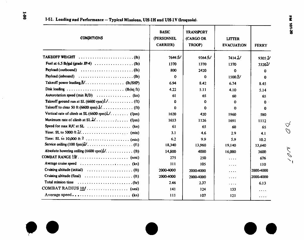
1-90 1-51. Loading and Performance — Typical Missions, UH-1H and UH-1V (Iroquois).
CONDITIONS
TAKEOFF WEIGHT (lb)
Fuel at 6.5 ib/gal (grade JP-4) (lb)
Payload (outbound) (lb)
Payload (inbound) (lb)
Takeoff power loading^/ (Ib/SHP)
Disk loading (Ib/sq ft)
Autorotation speed (min R/D) (kn)
Takeoff ground run at SL (6600 rpm)L/ (ft)
Takeoff to clear 50 ft (6600 rpm)i/ (ft)
Vertical rate of climb at SL (6600 rpm)L/ (fpm)
Maximum rate of climb at SL!/ (fpm)
Speed for max R/C at SL (kn)
Time: SL to 5000 ft 2/. (min)
Time: SL to 10,000 ft 2 (min)
Service ceiling (100 fpm)2/ (ft)
Absolute hovering ceiling (6600 rpm)!/. (ft)
COMBAT RANGE (nmi)
Average cruise speed (kn)
Cruising altitude (initial) (ft)
Cruising altitude (final) (ft)
Total mission time (hr)
COMBAT RADIUS 10/ (nmi)
Average speed (kn)
BASIC
(PERSONNEL
CARRIER)
7644i/
1370
800
0
6.94
4.22
61
0
0
1620
1653
61
3.1
6.2
18,340
14,800
275
111
2000-4000
2000-4000
2.46
141
111
TRANSPORT
(CARGO OR
TROOP)
9264iy
1370
2420
0
8.42
5.11
65
0
0
420
1126
65
4.6
9.9
13,960
4000
250
105
2000-4000
2000-4000
237
124
107
LITTER
EVACUATION
7414.1/
1370
0
1500 9/
6.74
4.10
60
0
0
1960
1691
60
2.9
5.9
19,140
16,000
133
121
FERRY
93051/
33202/
0
0
8.45
5.14
65
0
0
580
1112
65
4.1
10.2
13,640
3600
676
110
2000-4000
2000-4000
6.13
e »
3
\
• • • • •

1-9
1
• • • • • 1-51. Loading and Performance — Typical Missions, UH-1H and UH-1V (Iroquois) (Con’t).
CONDITIONS
BASIC
(PERSONNEL
CARRIER)
TRANSPORT
(CARGO OR
TROOP)
LITTER
EVACUATION FERRY
Cruising altitude (outbound) (min/max) (ft)
(ft)
(hr)
(lb)
(ft)
(ft)
(lb)
(ft)
(kn)
Combat climbZy. (fpm)
Cruising altitude (inbound) . .
Total mission time
FIRST LANDING WEIGHT^/. .
Ground roll at SL (6600 rpm)
Total from SO ft (6600 rpm) .
COMBAT WEIGHT!/
Combat altitude
Combat speed4/.
Combat ceiling (S00 ft/min)2/
Service ceiling (100 ft/min^/
Absolute hovering ceiling (6600 rpm)L/ .
Takeoff ground run at SL (6600 rpm)lY .
Takeoff to dear SO ft (6600 rpm)i/. . . .
Maximum rate of climb at Sl2J.
Speed for max R/C at SL
Max speed at SLl/
(ft)
(ft)
(ft)
(ft)
(ft)
(fpm)
(kn)
(kn)
Basic'speed at 5000 ft4/ (kn)
LANDING WEIGHTS/ (lb)
Ground roll at SL (6600 rpm) (ft)
Total from 50 ft (6600 rpm) (ft)
2000-4000
20004000
2.73
6997
0
0
6197
20004000
116
2256
23,550
24,070
21,300
0
0
2232
55.9
120
120
6977
0
0
20004000
20004000
2.54
8584
0
0
6164
20004000
116
2276
23,694
24,210
21,400
0
0
2251
55.8
120
120
8584
0
0
20004000
20004000
2.38
6789
0
0
8289
20004000
120
1370
15,960
16,842
11,600
0
0
1399
62.0
120
120
6789
0
0
6316
20004000
116
2200
23,150
23,680
20,700
0
0
2178
56.1
120
120
6316
0
0
FM 101-20

1-92 1-51. Loading and Performance — Typical Missions, UH-1H and UH-1V (Iroquois) (Con’t).
-1/ Takeoff power.
2j Normal rated power.
-3/ For RADIUS mission if ladius is shown.
Vne limit.
1/ Includes crew of 2 at 400 lb.
6/ Includes crew of 1 at 200 lb.
U Includes two 150-gallon ferry tanks.
& Based on engine specification takeoff shaft horsepower.
-2/ Six 250-pound litter patients.
IS' Detailed descriptions of RADIUS and RANGE missions are same as shown in paragraph 1-38.
Performance Basis:
a. Reference operator’s Manual Army Model UH-1 H Helicopter TM 55-1520-210-10.
b. All data are at 6600 rpm unless otherwise noted.
Source: TSARCOM-DRSTS-WU
• • • • • F
M 101-2
0

FM 101-20
1-52. Performance Notes, UH-1H and UH-1V (Iroquois).
FORMULA: RADIUS MISSION I
Warm up, take off, climb on course to 2000-4000 feet initial altitude at normal rated power, proceed at long range cruise speed to remote base, land, and unload passengers. Without refueling, warm up, take off, climb on course to 2000-4000 feet at normal rated power, and return at long range cruise speed. Range-free allowances are 4 minutes at normal rated power for warmups and takeoffs plus 10 percent of initial fuel for reserve.
FORMULA: RADIUS MISSION II
Warm up, take off, and climb on course to 2000-4000 feet at normal rated power. Cruise climb on course at long range cruise speed to final altitude of 2000-4000 feet. Proceed at long range speed to remote base, land, and unload cargo or troops. Without refueling, warm up, take off, climb on course to 2000-4000 feet at normal rated power, and return at long range cruise speed. Range-free allowances are 4 minutes at normal rated power for warmups and takeoffs plus 10 percent of initial fuel for reserve.
climb on course to 20004000 feet at normal rated power, and return at long range cruise speed. Range-free allowances are 4 minutes at normal rated power for warmups and takeoffs plus 10 percent of initial fuel for reserve.
FORMULA: RANGE MISSION I
Warm up, take off, and climb on course to 2000-4000 feet initial altitude at normal rated power. Proceed at long range cruise speed to remote base and land. Range-free allowances are 2 minutes at normal rated power for warmup and takeoff plus 10 percent of initial fuel for reserve.
FORMULA: RANGE MISSION II
Warm up, take off, and climb on course to 20004000 feet at normal rated power. Cruise climb on course at long range cruise speed to final altitude of 20004000 feet. Proceed at long range cruise speed to remote base and land. Range-free allowances are 2 minutes at normal rated power for warmup and takeoff plus 10 percent of initial fuel for reserve.
FORMULA: RANGE MISSION III
FORMULA: RADIUS MISSION III
Warm up, take off, and climb on course to 20004000 feet at normal rated power. Proceed at long range cruise speed to remote base, land, and pick up litter patients. Without refueling, warm up, take off,
Warm up, take off, and climb on course to 20004000 feet at normal power. Cruise climb on course at long range cruise speed to final altitude of 20004000 feet. Proceed at long range cruise speed to remote base and land. Range-free allowances are 2 minutes at normal rated power for warmup and takeoff plus 10 percent of initial fuel for reserve.
Source: TSARCOM- DRSTS-WU TSARCOM- DRCPM-AEL
1-93

FM 101-20
DIMENSIONS
Rotor día Length:
Rotors operating ...
Rotors static.. Fuselage
Span (max lateral)
Height Tread Gnd clearance
(static, against stops)
48 Ft.
.... 57 Ft. 1 In.
.... 57 Ft. 1 In. 41 Ft. 11 1/4 In.
9 Ft. 4 In. . 14 Ft. 5-1/2 In. ..8 Ft. 6-1/2 In.
,6 Ft. 6 In
7 FT 8-7/16 IN
9 FT 13/32 IN.—
— 8 FT 6-39/64 IN. -
9 FT 4 IN.
2 FT 61/2 IN.
44 FT 10-3/32 IN
II FT 8-21/32 IN.
8 FT 6 N.
SS E3 11 FT 9-3/4 IN.
□ □ ŒJ
I FT 3 IN. GROUND LINE DESIGN GROSS WEIGHT
40 FT 7-3/32 IN
41 FT 11-5/32 IN
Figure 1-30. Principal Dimensions, UH-1V (Iroquois)
1-94
14 F
T 5
-1/2
IN
.

1-95
1-53. UH-1V (Iroquois) Characteristics.
ENGINE MISSION AND DESCRIPTION WEIGHTS
No. & model . . .
Mfr Type Red. gear ratio . Tailpipe Augmentation .
(1)T53-L-13B
Lycoming 104.33 0.312 Fixed area None
ENGINE RATINGS
T53-L-13B Output
Rating/SL Slff SEC RPM Kill 1400* 0.580 6300 NRP 1250* 0.598 6040
* 1400 SHP flat rated to 1I00SHP.
TECHNICAL PUBLICATION
AIRFRAME: TM 55-1500-219-L TM 55-1500-219-MTF TM 55-1520-210-CL TM 55-1520-210-PM TM 55-1520-210-PMD TM 55-1520-210-10 TM 55-1520-210-23 TM 55-1520-242-S TM 55-1520-210-23P
ENGINE: TM 55-2840-229-23 TM 55-2840-229-23P DMWR 55-2840-113
Mfr’s Model: Bell 205
The UH-1V is a UH-1H converted to a medical evacuation aircraft, the only difference in the conversion is installation of DME and a radar altimeter. This aircraft will be furnished all med evac units.
DEVELOPMENT
First flight (Similar aircraft) First acft delivered , Mar 79
CAPACITIES
Inside clearance Cargo area: Length(overall)..7 ft,8 in. Width(floor level) 8 ft
Height (max) 4 ft,l in. Copilot area: Length(overall)..3 ft,7 in. Width 2 ft,7 in. Height(max) 4 ft
Main cargo door Height 4 ft Width (max) 6 ft,2-1/2 in. Height above ground 2 ft
Limit floor loads Cargo area 300 Ib/sq ft Copilot area 75 Ib/sq ft
Usable cubage Capacity Cargo area 220 cu ft Copilot area 20 cu ft
PERSONNEL
Basic mission Crew 1 Passengers 4
Alternate Crew 1 Passengers 12
Litter evacuation Crew(pilot & medical attendant) 2
Litters 6 Cargo
Crew 1 Kerry mission
Crew(pllot & copilot) 2
LB L.F. Empty
5132 Design 6600 3.0 Combat 9500 2.2 Max takeoff 9500 2.2 Max landing 9500
FUEL AND OIL
Euel: Grade JP-4/5 Spec MIL-T-5624 No. tanks:
Fuselage (1) 209 gal Ferry (1) 300 gal
Total qty 509 gal OU:
Spec MIL-L-23699 or
MIL-L-7808 No. tanks 1 Location Fuselage Qty 4-1/2 gal
AVIONICS / ARMAMENT
Refer to chapter 2.
UNIT PRICE/NSN
NSN, 1520-01-043-4949,
UNIT PRICE: Refer to Table 4-1. F
M101-20

FM 101-20 D d V-o
DIMENSIONS
Rotor dia 48 Ft. Length:
Rotors operating 57 Ft. 1 In.
Rotors Static 57 Ft. 1 In. Fuselage 41 Ft 11-1/4 In. Span (max
Lateral) 9 Ft. 4 In. Height 14 Ft. 5-1/2 In. Tread 8 Ft. 6-1/2 In. Gnd clearance
(static, against stops) 6 Ft. 6 In.
— 9 FT 13/32 IN.
8 FT 6-39/64 IN.
1-1 FT.9IN.
D 48 F*
rx=! D
2 FT 6-1/2 IN.
9 FT 4 IN.
44 FT 10-3/32 IN.
11 FT 8-21/32 IN.
8FT6IN
1=3 c5 a 11 FT 9-3/4 IN. Si uS
J □ □ & GROUND LINE DESIGN GROSS WEIGHT 1 FT 3 IN.
40 FT 7-3/32 IN. 41 FT 11-5/32 IN.
Figure 1-31. Principal Dimensions, EH-1H (Quick fix)
1-96

1-97
1-54. EH-1H (Quick Fix) Characteristics.
ENGINE MISSION AND DESCRIPTION WEIGHTS
No. & model..
Mfr Type Red. gear ratio Tailpipe Augmentation
(DT53-L-
Lycoming 104.33 0.312 Fixed area None
13B
ENGINE RATINGS
T53-L-13B
Rating/SL SHP MU 1400* 0.580 NRP 1250* 0.598
Output SFC RPM
6300 6040
* 1400 SHP flat rated to 1100 SHP.
TECHNICAL PUBLICATION
AIRFRAME: TM 55-1500 TM 55-1500 TM 55-1520 TM 55-1520 TM 55-1520 TM 55-1520 TM 55-1520 TM 55-1520 TM 55-1520
■219-L ■219-MTF ■210-CL ■210-PM ■210-PMD -210-10 -210-23 ■242-S -210-23P
ENGINE: TM 55-2840-229-23 TM 55-2840-229-23P DMWR 55-2840-113
The EH-1H is a modified UH-1H configured to carry ECM equipment in the passenger/cargo area. The basic dynamic components and airframe are the same as the standard aircraft.
The mission for the EH-1H weapon system consists of air- borne search, collection and jamming countermeasures of enemy single channel radio communications. This information is provided to Division/Brigade commanders in tactical situa- tions. Recording/Reproducing capability is also included in the information collection system.
DEVELOPMENT
Date of contract, MIPR 23 Jun 75 Contracting agency NARF Pensacola No. of test aircraft 1 First flight (scheduled) 4 Aug 77 Completion of test and evaluation.. 16 Mar 77 Contract delivery schedule 1 Jun 78
FEATURE
Crashworthy Fuel System Retractable Antennas 30 KVA Alternator
PERSONNEL
Pilot Copilot Mission Operators.
LB L.F. Empty
6258 Design 9500 Combat 9500 Max takeoff 9500 Max landing 9500
FUEL AND OIL
Fuel: Grade JP-4/5 Spec MIL-T-5624 No. tanks:
Fuselage (1) 209 gal Ferry (1) 209 gal
Total qty 509 gal OU:
Spec MIL-L-23699 or
MIL-L-7808 No. tanks 1 Location Fuselage Qty 4-1/2 gal
AVIONICS / ARMAMENT
Refer to chapter 2.
UNIT PRICE/NSN
NSN 1520-00-368-8442 LINE K 30548
UNIT PRICE: Refer to Table 4-1.
d

FM 101-20
^ ÀJÛ~
DIMENSIONS
Rotor dia Length:
Rotors operating...
Rotors Static . Fuselage Span (max
Lateral) Height Tread Gnd clearance
(static, against stops)
48Ft.
57 Ft. 1 In. 57 Ft. 1 In. 41 Ft. 11-1/4 In.
9 Ft. 4 In. .14 Ft. 5-1/2 In. .'.8 Ft. 6-1/2 In.
6 Ft. 6 In.
— 9FT13/32IN.-H
8 FT 6-39/64 IN.
1 FT. 9 IN
9 FT 4 IN.
D 48^
n 2 FT 6-1/2 IN.
44 FT 10-3/32 IN.
11 FT 8-21/32 IN.
8 FT 6 IN.
11 FT 9-3/4 IN. □ □ L 3R0UND LINE DESIGN GROSS WEIGHT 1 FT 3 IN.
40 FT 7-3/32 IN. 41 FT 11-5/32 N
Figure 1-32. Principal Dimensions, EH-1X (Quick Fix II)
1-98
14 F
T 5
-1/2
IN
.

1-99 • • • • •
1-55. EH-1X (Quick Fix II) Characteristics.
ENGINE MISSION AND DESCRIPTION WEIGHTS
No. & model . .
Mfr Type Red. gear ratio Tailpipe ... . Augmentation
( 1 )T53-L-
Lycoming 104.33 0.312 Fixed area None
13B
ENGINE RATINGS
T53-L-13B
Rating/SL SHP Mil 1400* 0.580 NRP 1250* 0.598
Output SFC RPM
6300 6040
* 1400 SHP flat rated to 1100 SHP.
TECHNICAL PUBLICATION
AIRFRAME: TM55-1520-210-10 TM55-1520-210-23 TM55-1520-210-23P TM55-1520-210-PM TM55-1520-210-PMD
ENGINE: TM55-2840-229-23 TM55-2840-229-23P DMWR 55-2840-113
MFRS MODEL: BELL 205 The Phase II QUICK FIX system is an airborne intercept,
jamming & direction finding (DF) system. The system is designed to have up to 3 AJC operating simultaneously. Each AJC has the capability to initiate DF action on a target. During multiple AJC operation, DF commands are transmitted via a secure digital data link, to command the other AIC to take DF bearings on the same target. Resulting Lines of Bearing & AJC position are returned to the initiating AJC via the same data link. The EH-1X is a modified UH-1H using the basic airframe, components and powerplant.
DEVELOPMENT
Date of Contract Jan 79 No of Test Aircraft 1 Follow on evaluation July 80
FEATURES
30 KVA Alternator Crash Worthy Fuel System Lightweight Avionics
PERSONNEL
Pilot Copilot Mission Operators
LB L.F. Empty
7025 Design 9500 Combat 9500 Max takeoff 9500 Max landing 9500
FUEL AND OIL
Fuel: ôrade JP-4/5 Spec MIL-T-5624 No. tanks:
Fuselage (1) 209 gal Ferry (1) 209 gal
Total qty 509 gal OU:
Spec MIL-L-23699 or
MIL-L-7808 No. tanks 1 Location Fuselage Qty 4r 1/2 gal
AVIONICS / ARMAMENT
Refer to chapter 2.
UNIT PRICE/NSN
NSN 1520-01-042-9396 LINE, H30829
UNIT PRICE: Refer to Table 4-1.
FM
101-20

FM 101-20
1-56. Loading and Performance — Special Mission, EH-1H and EH-1X (Estimated).
CONDITIONS SPECIAL MISSION
Take-off weight (lb) 9500 Take-off distance (ft) 0 Rate-of-climb (fpm) 1000 Service ceiling (ft) 13000 Cruise speed (kn) 105 kns Max speed (kn) 120 kns Endurance (hr) (1.5 hrs on station ) 2.0 Landing distance (ft) 0
1-57. Performance Notes, EH-1H and EH-1X (Iro- heavily loaded UH-1H; however, does not have quois). troop carrying or extended range capabilities.
Performance of these aircrafts are similar to a

FM 101-20
y
©
Figure 1-33. UH-60A (Black Hawk)
fj
1-101

FM 101-20 ¿2 ¡0^0 *
DIMENSIONS
Rotor Dia 53 Ft. 8 In. Length:
Rotors Operating 64 Ft. 10 In. Static
Fuselage 50 Ft. .75 In.
Span (Max Lateral) 9 Ft. 8.6 In. Height 16 Ft. 10 In. Tread 8 Ft. 10.6 In.
Ground Clearance Static 7 Ft. 8.5 In.
T/ I!
/
X X TURNING
RADIUS 41 IN.-7.7 IN.
/ /
lu I /
□ □
/ /
\ / \ \
11 FT -0 IN. ROTOR DIAMETER
rn- 12 FT-5. IN
9 FT-5 IN. 8 FT -9 IN. ROTOR ROTOR TURNING STATIONARY
□ □ r -■b 6 FT.-6 IN FT -0 IN
3 FT-0 IN. {
H FT.-11 IN 11 FT. -3 IN WHEEL BASE 29 FT.-0 IN. 12 FT.-8 IN.
Figure 1-34. Principal Dimensions, UH-60A (Black Hawk)
1-102

eoï-i
t • • •
1-58. UH-60A (Blackhawk) Characteristics.
ENGINE MISSION AND DESCRIPTION WEIGHTS
No. & model .. (2)T700-GE-700 Mfr General Electric Engine spec. no.
.. DARCOM-CP-2222-02000
Type Turboshaft
Length 46.5 In. Width 25 In. Height 23 In. Weight 415 Lbs.
ENGINE RATINGS
Standard Sea Level Conditions SHP RPM
Max Continuous 1240 20900 IRP 1543 20900
TECHNICAL PUBLICATION
AIRFRAME: TM 11-1520- TM 11-1520- TM 11-1520- TM 55-1500- TM 55-1520 TM 55-1520- TM 55-1520- thru TM 55-1520 TM 55-1520- TM 55-1520- TM 55-1520- TM 55-1520- TM 55-1520- TM 55-1520 TM 55-1520
237-23-1 237-23-2 237-23-3 237-5 -237-10 -237-23 -237-23-1
-237-23-10 -237-23P -237-23P-1 -237-23P-2 -237-CL -237-MTF -237-PMS-l -237-PMS-2
ENGINE: TM 55-2840-248-23 TM 55-2840-248-23P
The Blackhawk helicopter will perform primary and second- ary missions of transporting internal loads under visual and instrument conditions day and night and external loads under visual flight conditions.
The Blackhawk (UH-60A) is a twin engine rotary wing air- craft which will carry eleven (11) combat equipped troops and a crew of three (3). Optional seating allows up to 14 combat equipped troops. When used as an aerial medical evacuation vehicle it will accomodate 4 litter patients and a medical attendant. An external cargo hook with 8,000 lbs. load capacity and provisions for an internal high performance rescue hoist are also provided. The UH-60A is designed to operate in temperatures from —65°F to + 125°F.
DEVELOPMENT
Date of Contract First Flight (similar aircraft). First Production Aircraft
. Nov 1976 . Oct 1974 . Oct 1978
CAPACITIES
Cargo Apartment Floor
Length 110” Length (including crew chief station) 151” Width Height
Cargo Door Height Width
72” 53.5”
54” 68”
PERSONNEL
Crew 3 Troops 11 (optional troop seatings) 14
Litters 4 Attendant 1
LOADING LB
Empty 10,680 Design Gross 16,326 Max Alternate 20,250
FUEL AND OIL
Fuel: Grade JP-4 Spec MIL-T-5624 Alternate JP-5 Emergency ..
No. Tanks 2 Location Rear Fuselage Qty 362 Gallons
OU: Engine Spec Alternate. No. Tanks Location..
Transmission: Spec Alternate...
. MIL-L-23699
. MIL-L-7808 ,1 , Main Frame —
Engine
MIL-L-23699 MIL-L-7808
AVIONICS / ARMAMENT
Refer to chapter 2.
UNIT PRICE/NSN
NSN 1520-01-035-0266, LIN K32293, Unit Cost: Refer to Table 4-1.
FM 101-20

W)I
“I
1-59. Loading and Performance i/. Typical Missions, UH-60A (Black Hawk). 3
ha CONDITIONS COMBAT ASSAULT
SEA LEVEL COMBAT ASSAULT
4000’/95°F MAX ALT GROSS WT SEA LEVEL
MAX ALT GROSS WT
4000’/95F
FERRY MISSION STD DAY
NO OF TROOPS/PAYLO AD 11 14 11 14
^/Estimated Gross Weight (lbs)
Payload (Outbound) (lbs)
Payload (Inbound) (lbs)
Vmax(IRP)(kts)
Max Cruize Speed (MCP) (kts)
Vcruize (Best Range) (kts)
Max Rate-of-Climb (IRP-Vbroc) (fpm)
Vert Rate-of-Climb (95% IRP) (fpm)
Service Ceiling (100 fpm) (ft)
Service Ceiling (Single Eng) (ft)
Hover Ceiling (Oge. IRP) (ft)
Hover Ceiling (2 ft Wheel Ht. IRP) (ft)
^/Radius of Action (nm)
Ferry Range (nm)
16700
2640
0
157
150
130
2735
1515
18,000
8700
9800
14800
106
17420
3360
0
156
149
130
2550
1220
17200
7500
8600
13600
105
16700
2640
0
156
137
135
2010
290
14000
3600
5000
9200
133
17420
3360
0
155
136
135
1840
13000
2400
4200
8400
133
20250
6195
3000
1284/
1211/
1001/
1645
13700
3000
4800
9600
901/
20250
6195
3000
1291/
1051/
1051/
1075
9800
4000
1101/
1/ Performance with IR Suppressor Installed. 2/Empty Wt -10680 lbs. Fixed Useful Load with Crew of 3 - 935 lbs 3/8 Min Ground Time, 1 Min Hover, Climbout, Vcruise, 5 Min Noe at 40 Kts & Return with 30 Minute Reserve. 4/Outbound Payload is External 30ft2 Equivalent Flat Plate Area
19500
149
143
126
2045
14600
4200
5000
10400
950
Source: AVRADC0M - DRCPM-BH
# • • •

FM 101-20
0 9o 9o
s
Figure 1-35. C-12A, C & D (Huron)
1-105

FM 101-20 43 FT 10 IN.
15 FT .5 IN D QOOOO O Œ2I
14.5 IN. o o
*14 FT 11 5 IN.
29.6 IN
d
18 FT 5 IN.
DIMENSIONS
Wing Span (A&C model)... 54 Ft. 6 In. Wing Span (D model).... 55 Ft. 6.5 In. Length 43 Ft. 10 In. Height 15 Ft. 5 In. Tread 17 Ft. 2 In. Prop Grd Clearance 1 Ft.
55 FT. 6.5 IN. ■54 FT. 6 IN.
wA-m
8 FT. 2.5 IN. DIA
17 FT. 2 IN:
-D MODEL -A&C MODELS
Figure 1-36. Principal Dimensions, C-12A, C & D (Huron) 1-106

1-107 • • • • • 1-60. C-12A, C & D (Huron) Characteristics.
ENGINE MISSION AND DESCRIPTION WEIGHTS
No. and Model C-12A (2) PT6A-38 No. and Model C-12C&D .. (2) PT6A-41 Mfr UACL Type Turbo Prop Prop Mfg Hartzell Prop Type C5 No. Blades 3 Prop Dia 8 Ft. 254 In.
ENGINE RATINGS
C-12A TAKEOFF SHP 750 ALT SL C-12C&D TAKEOFF SHP 850 ALT SL
TECHNICAL PUBLICATIONS
AIRFRAME: TM 55-1510-218-10 Commercial Manuals (Contractor Supported)
ENGINE: Pratt and Whitney Commercial Manuals
Mfg. Model: Beech Aircraft Corp. A200 LOADING LB.
The C-12A, C & D are off-the-shelf utility aircraft which are totally contractor supported.
The C-12A, C & D are all metal twin turbo prop engine, fixed wing, pressurized cabin, passenger/cargo carrying aircraft. The aircraft are designed and equipped for flight operations under Instrument Flight Rule (IFR) conditions day or night into high density air traffic control zones and into known icing weather conditions.
Empty Basic Design 12,500
Clean Light Scout Heavy Scout Hog
Max. Takeoff Max. Landing 12,500
DEVELOPMENT
Date of contract First flight (similar aircraft) First aircraft delivered
FUEL AND OIL
.. Aug 1974 TSARCOM ... Sep 1975
Fuel: Grade ... Spec No. tanks
JP 4/5 MIL-T-5624 12
Location 10 Wing 2 Nacelle
Qty 386 (544 w/ Aux Tanks)
FEATURES PERSONNEL
All Metal T-Tail Retractable Tricycle with
Dual Main Wheel Dual Side-by-Side Flight Controls
Crew Passengers
Oil: Spec MIL-L-23699 No. tanks 2 Location Nacelle Qty 3.5 Gal Each Tank
AVIONICS/ARMAMENT
Refer to Chapter 2.
UNIT PRICE/NSN
NSN 1510-01-005-5461
UNIT PRICE: Refer to Table 4-2.
FM
101-20

FM 101-20
1-61. Performance — Typical Mission, C-12A, C & D (Huron).
A Model C & D Models
Payload Range Cruise Speed Max Speed Min Takeoff Distance.. Min Landing Distance . Rate of Climb (1 Eng).. Service Ceiling (2 Eng). Service Ceiling (1 Eng).
• • db) . (nmi) .. (kn) .. (kn) • ••(ft) • • • (ft) (fpm)
• • • (ft) ... (ft)
4764 @31,000 1177 Aux Tanks 1780
@25,000 24131,000 222 270
3824 2620
602 30,400
4391 1755
260 2200
700 31,000
SOURCE: TSARCOM-DRSTS-WP
1-108

\
FM 101-20
I
Figure 1-37. OV-1 (Mohawk)
1-109

12 F
T 9-3
/4 I
N.
FM 101-20
48 FT
DO y
10 FT
T 2 IN. STATIC
15 FT 10 IN. — DIMENSIONS
Wing:
Area 360 Sq. Ft Span 48 Ft MAC 94.8 In Length 43 Ft. 11-1/2 In Height 12Ft. Sin Tread 9 Ft. 2 In
n/r! rWri
n n V U
a
fia V -I I FT 8-1/4 IN. J
43 FT 11-3/8 IN
Figure 1-38. Principal Dimensions, OV-1B (Mohawk)
1-110

1-111
1-62. 0V-1B (Mohawk) Characteristics.
ENGINE MISSION AND DESCRIPTION
No. & model .... (2) T53-L-7A Mfr Lycoming Type Free power
turbine Engine spec No .. 104.21C Red. gear ratio ... 12.4 Prop mfr Hamstd Blade design No . 7125-6 No. of blades ... 3 Propdia 10 ft
ENGINE RATINGS
Output
Rating/SL SHP SFC RPM Max (takeoff) 1100 0.670 1700 MU 1000 0.679 1700 NRP 900 0.692 1700
TECHNICAL PUBLICATION
Mfr’s Model: Grumman
The primary mission of the OV-1B is electronic surveillance us- ing the sidelooking airborne radar (SLAR). In addition, it is capable of performing missions of photographic reconnaissance, visual reconnaissance and observation, artillery gunfire spot- ting, and air control.
The OV-1B is a two-place, twin-turboprop aircraft capable of operating from improved runways. Design features include a midwing, three-tail configuration of semimonocoque construc- tion equipped with wide span flaps.
The crew of two are seated side-by-side within a bubbled enclosure at the extreme forward end of the fuselage.
A remotely operated day-and-night KA-30 camera installation provides horizon-to-horizon photo coverage along the aircraft flight path.
The OV-IB carries an APS-94 side looking airborne radar antenna as standard equipment.
External provisions are incorporated to carry two 150-gallon fuel tanks or two resupply containers.
AIRFRAME: TM 55-1510-204-10/3 TM 55-1510-204-CL/3 TM 55-1510-204-23-1 TM 55-1510-204-23-2 TM 55-1510-204-23-3 TM 55-1510-204-23-4 TM 55-1510-204-23P-1 TM 55-1510-204-23P-2 TM 55-1510-204-23P-3 TM 55-1510-217-L TM 55-1510-217-PM TM 55-1510-217-PMD TM 55-1510-217-S
DEVELOPMENT
First flight (prototype) .. Estimated first service use
November 1961 January 1963
FEATURES PERSONNEL
Ejection Seats Low Physical Profile All Weather Operation
Capability Capable of Deployment to Distant MSN Area by Using Extended Range Tanks (300 gal)!
Pilot Mission Operator.
ENGINE: TM 55-2840-233-24 TM 55-2840-233-23P
WEIGHTS
LB L.F. Empty E 10,983 Basic 11.217 Design 13,100 4.0 Combat (basic
mission) 12,882 Normal takeoff . 13,654 ' Max takeoff ... 16,643 Max landing ... 16,643
FUEL AND OIL
Fuel: Grade JP-4 Spec MILT-5624
No. tanks: Fuselage External Total Qty
OU: Spec ... Qty ....
(1) 297 gal (2) 150 gal 597 gal
MIL-L-23699 5 gal
AVIONICS / ARMAMENT
Refer to chapter 2.
UNIT PRICE/NSN
NSN 1510-00-715-9379
LIN A30221 UNIT PRICE: See Table 4-2.
FM
101-20

1-112
1-63. Loading and Performance — Typical Mission, OV-1B (Mohawk)
TAKEOFF LOADING CONDITION OBSERVATION,
NO STORES 1
NIGHT PHOTO, TWO A6
EJECTORS 3
EMERGENCY RESUPPLY,
TWO RESUPPLY CONTAINERS
5
FERRY, TWO 150-GAL
EXT TANKS ?
TAKEOFF WEIGHT (lb) Fuel intemal/extemal (lb) Payload (lb) Wing loading (lb/sq ft) Stall speed (power-off) 4/ (kn) Takeoff run at SL - calm (ft) Takeoff to clear 50 ft - calm (ft) Max speed/altitude 1/ (kn/ft) Rate of climb at SL ^ (fpm) Time: SL to 20,000 ft 2/ (min) Time: SL to 25,000 ft 2/ (min) Service ceiling ( 100 fpm) 2/ (ft) COMBAT RANGE J/ (nmi)
Average cruising speed (kn) Cruising altitude (s) (ft)
Cruise time (hr) Mission time (hr)
13,654 1930/0
38 73
1140 1660
240.5/12,500 2800
9.5 15.5
29,500 365 200
5000 1.80 1.84
13,915 1930/0
264 38.7 73.8
1230 1800
238/12,000 2700
10 16
28,750 358 200
5000 1.77 1.80
15,168 1930/0
1500 42.1
77 1520 2170
226.8/10,000 2320
13 23
26,500 334 200
5000 1.64 1.69
15,918 1930/1950
44.6 79
1650 2320
226/8000 2160
15 26.5
24,900 1053 203
20,000 4.98 5.30
COMBAT LOADING CONDITION NO STORES 2
TWO A6 EJECTORS
4
TWO RESUPPLY CONTAINERS
6
COMBAT WEIGHT (60 percent internal fuel). (lb) Engine power Fuel (lb) Combat speed/combat altitude 2/.... (kn/ft) Rate of climb/combat altitude 2/.... (fpm/ft) Combat ceiling (500 fpm) 2/. (ft) Rate of climb at SL 2/ (fpni) Max speed at SL 2/ (kn) Max speed/altitude 2/ (kn/ft)
LANDING WEIGHT (10 percent internal fuel) (lb) Fuel (lb) Stall speed-power-off/approach power ■S'... (kn) Landing distance clear 50-ft obstacle ... (ft)
12,882 Military
1158 250/5000
2660/5000 27,700
3050 247.2
252/11,500 11,917
193 82/68
1650
13,143 Military
1158 248/5000
2560/5000 26,900
2940 244.9
249.5/11,500 12,178
193 83/68
1740
14,396 Military
1158 238/5000
2175/5000 23,800
2530 235.9
239.5/10,000 13,431
193 87/72
1910
FM
101-20

1-63. Loading and Performance — Typical Mission, OV-1B (Mohawk) (Con’t).
-1/Normal rated power.
^Military rated power.
-3/ See notes on mission specifications.
4/Flight idle power, propeller control at max rpm.
Power for level flight at 120 percent of stall speed, power off, propeller control at max rpm.
Source: TSARCOM-DRCPM-AEL

FM 101-20
C?
r
Figure 1-39. OV-1C (Mohawk) Aircraft
1-114

12 F
T.
U M
.
FM 101-20
42 FT.
un 10 FT.
[— 9 FT. 2 IN STATIC-j DIMENSIONS
Wing: Area 330 Sq. Ft. Span 42 Ft. MAC 98 In. Length 41 Ft. 3.65 In. Height 12 Ft. 9.75 In. Tread 9 Ft. 2 In.
19 FT. 10 IN
r'7r“!
n \! \i
D ä if ■ II FT. 8-1/4 IN. —I
41 FT. 3A9 M.
Figure 1-40. Principal Dimensions, OV-lC (Mohawk)
1-115

1-116
1-64. 0V-1C (Mohawk) Characteristics.
ENGINE MISSION AND DESCRIPTION WEIGHTS
No. & model .... (2)T53-L-7A Mfr Lycoming Type Power free
turbine Engine spec No 104.11C Red. gear ratio 12.46 Prop mfr Ham std No. blades 3 Blade design No 7125-6 Prop dia 10 ft
ENGINE RATINGS
T53-L-7A
Rating/SL SHP SFC Max (takeoff) 1100 0.670 Mil 1000 0.679 NRP 900 0.692
Output RPM 1700 1700 1700
Mfr’s Model: Grumman
The primary mission of the OV-lC is to perform Infrared (IR) recon- naissance missions using the Infrared sensor. In addition it is capable of performing photographic missions, visual reconnaissance and observa- tion, artillery gunfire spotting and air control.
The OV-lC is a two-place, twin turboprop aircraft capable of operating from improved runways. Design features include a midwing, three-tail configuration of semi-monocoque construction equipped with wide span flaps.
The crew of two are seated side-by-side within a bubbled enclosure at the extreme forward end of the fuselage.
A remotely operated day-and-night KA-30 or KA-76 camera installa- tion provides horizon-to-horizon photo coverage along the aircraft flight path. A nose-mounted KA-60, 70-mm panoramic camera is also provided.
The OV-lC carries AN/AAS-14 infrared detection equipment. An LS- 59A Flasher Pod maybe installed externally. The infrared surveillance system makes it possible to detect military terrestrial targets by inherent characteristics that are distinguishable in the visual and infrared portion of the electromagnetic spectrum.
External provisions are incorporated to carry two 150-gallon fuel tanks or two resupply containers.
DEVELOPMENT
TECHNICAL PUBLICATION
First flight (prototype) First service use
AIRFRAME: TM 55-1510-204-10/4
TM 55-1510-204-CL/3 TM 55-1510-204-CL/4 TM 55-1510-204-23-1, -2, -3, -4 :
TM 55-1510-204-23P-1, P-2, P-3 TM 55-1510-217-L TM 55-1510-217-PM TM 55-1510-217-PMD TM 55-1510-217-S
ENGINE TM 55-2840-233-24
' TM 55-2840-233-23P
FEATURES
Ejection Seats Low Physical Profile All Weather Operation
Capability
Capable of Deployment to Distant MSN Area by Using Extended Range Tanks (300 gal)
March 1961 July 1961
PERSONNEL
Pilot Mission Operator.
LB Empty 10,011 Basic 10,379 Design 11,924 Combat (basic
mission) 12,296 Normal takeoff . 12,682 Max takeoff ... 15,302 Max landing ...15,302
L.F.
4.9/4.0
FUEL AND OIL
Fuel: Grade JP-4 Spec MIL-T-5624 No. tanks:
Fuselage .... (1) 297 gal External (2) 150 gal
Total qty 597 gal OU:
Spec MIL-L-23699 Qty 5 gal
AVIONICS / ARMAMENT
Refer to chapter 2.
UNIT PRICE/NSN
NSN 1510-00-715-9380 LIN A30271 UNIT PRICE: See Table 4-2.
FM
101-20

1-117
1-65. Loading and Performance — Typical Mission, OV-1C (Mohawk).
TAKEOFF LOADING CONDITION
TAKEOFF WEIGHT (lb) Fuel (lb) Paylo;-"! (lb) Wing loading (lb/sq ft) Stall speed (power-off) 4/ (kn) Takeoff run at SL - calm^ (ft) Takeoff run at SL - 25-kn wind & (ft) Takeoff to clear 50 ft - calm & (ft) Max speed/altitude ^ (kn/ft) Rate of climb at SL (fpm) Time: SL to 20,000 ft 2^ (min) Time: SL to 25,000 ft-K2/ (min) Service ceiling ( 100 fpm) 2/ (ft)
NIGHT PHOTO, OBSERVATION TWO A6
NO STORES EJECTORS 1 3
EMERGENCY RESUPPLY
TWO RESUPPLY CONTAINERS
5
FERRY, TWO 150-GAL
EXT TANKS 7
12,682 1930
38.4 72
1080 810
1640 246/10,000
2270 14/12 24/20
26,200/27,450
12,943 1930 264
39.2 73
1110 833 1680
243/10,000 2175 15/13 27/22
25,700/26,500
14,197 1930 1500 43.0
76 1400 1050 2000
229/5000 1800
22/17 47/35
21,600/23,200
14,961 3880
45.3 77
1560 ' 1150
2230 230/SL
1630 27/22 64/47
20,200/21,300
COMBAT RANGE 2J (nmi) Average cruising speed (kn) Cruising altitude(s) (ft)
Cruise time (hr) Mission time (hr)
408 200
5000 2.01 2.05
397 200
5000 1.96 2.00
362 200
5000 1.78 1.83
1081 215
20,000 4.72 5.17
COMBAT LOADING CONDITION
COMBAT WEIGHT (60 percent internal fuel) .. (lb) Engine power Fuel (lb) Combat speed/combat altitude 2/ (kn/ft) Rate of climb/combat altitude 2/ (fpm/ft) Combat ceiling (500 fpm) 2/ (ft) Rate of climb at SL 2/ (fpm) Max speed at SL 2/ (kn) Max speed/altitude 2/ (kn/ft)
LANDING WEIGHT (10 percent internal fuel) .. (lb) Fuel (lb) Stall speed-power off 4/ /approach power. (kn) Landing distance to clear 50-ft obstacle (ft)
NO STORES 2
TWO A6 EJECTORS
4
TWO RESUPPLY CONTAINERS
6
11,910 12,171 13,425 Military Military Military
1158 256/5000
2100/5000 25,200
2880 255
256/10,000 10,945
193 82/70
1800
1158 252/5000
2000/5000 24,300
2780 252
253/10,000 11,206
193 84/70
18403'
1158 240/5000
1620/5000 20,400
2320 239
240/5000 12,460
193 87/73
2000 S'
FM
101-20

1-118
1-65. Loading and Performance — Typical Mission, OV-1C (Mohawk) (Con’t).
-formal rated power.
-Military rated power.
-3/See notes on mission specifications.
^Flight idle power, propeller control at max rpm.
l^Power for level flight at 120 percent of stall speed, power off, propeller control at max rpm. .
^Takeoff distances are based on takeoff and obstacle speed equal to 120 percent of power-off stall
speed in takeoff configuration.
^Landing distance is based on approach speed equal to 110 percent of landing stall speed with rate of
sink equal to 14 fps.
-^Landing distance is based on approach speed equal to 110 percent of landing stall speed, power off,
with rate of sink equal to 8 fps.
FM
101-20

FM 101-20
1-66. Performance Notes, OV-1B and C (Mohawk).
TACTICAL AIR OBSERVATION MISSION AND NIGHT PHOTOGRAPHY (Columns 1, 3, and 5, paragraphs 1-63 and 1-66.
Warm up, taxi, take off, dumb on course to 5000 feet at normal rated power, and cruise at 200 knots at 6000 feet until all but reserve fuel is consumed. Range-free allowances are 5 minutes at normal rated power for warmup, taxi, and take off, plus 10 percent of initial internal fuel for reserve.
FERRY MISSION (Column 7, paragraphs 1-63 and 1-65).
Warm up, taxi, take off, climb on course to altitude for maximum range at normal rated power, cruise at altitude and velocity for maximum range until all but reserve fuel is consumed, and drop external fuel tanks when empty. Range-free allowances ar 5 minutes at normal rated power for warmup, taxi, and take off, plus 10 percent of initial fuel for reserve.
1-119

FM 101-20
fr
Figure 1-41. OV-1D (Mohawk)
1-120

FM 101-20
48 FT
TAIL SPAN 15 FT 10 IN
HORIZ WL 100
uo. \s/
10 FT
WL 9 WL 0.0
BL 0.0
STATIC TREAD - 9 FT 1.9 IN.—
DIMENSIONS
Wing Area 360 Sq. Ft. Span 48 Ft. MAC 98 In. Length 41 Ft.
3.65 In. Height 12 Ft. 8 In. Tread 9 Ft. 2 In.
VERTICAL REF LINE STA-5.75
HORIZ WL 100
(HORIZONTAL REF LINE) a 13 FT
12 FT 8 IN n □ Q
STATIC GL5”39 MIN
STATIC WHEEL BASE ■ 11 FT 8.2 IN. '
MAX LENGTH •41 FT. 3.65 IN.
(SLAR ANTENNA INSTALLED) 43 FT 3.25 IN.
Figure 1-42. Principal Dimensions, OV-1D (Mohawk)
1-121

1-122 1-67. 0V-1D (Mohawk) Characteristics.
ENGINE MISSION AND DESCRIPTION WEIGHTS
No. & model (2)T53-L-701A
Mfr Lycoming
Type Free power Turbine
Engine spec No 104.39
Red. gear ratio 12.38
Prop mfr Ham std
Blade design No 5157C-6
No of blades 3
Prop dia 10 ft
ENGINE RATINGS
T53-L-701A Rating/SL SHP
Output SFC RPM
MIL
NRP
1400 .590 1650
1250 .610 1590
TECHNICAL PUBLICATIONS
AIRFRAME: TM 55-1510-213-10 & 10-1 TM 55-1510-213-CL TM 55-1510-213-23-1, -2, -3 TM 55-1510-204-23P-1, P-2, P-3 TM 55-1510-217-L TM 55-1510-217-PMD TM 55-1510-217-PM TM 55-1510-213-MTF TM 55-1510-200-S
ENGINE: TM 55-2840-233-24 TM 55-2840-233-23P
The primary mission of the OV-1D is to perform either infrared (IR) reconnaissance or side looking airborne radar (SLAR) missions. The SLAR and IR are interchangeable. In addition, it is capable of performing photographic missions, visual recon- naissance and observation, artillery gunfire spot- ting and air control. The OV-1D is a two-place, twin turboprop aircraft capable of operating from im- proved runways. Design features include a mid- wing, three-tail configuration of semimonocoque construction equipped with wide span flaps.
The crew of two are seated side-by-side within a bubbled enclosure at the extreme forward end of the fuselage.
The OV-1D is equipped with three independent photographic systems, all of which have automatic exposure controls and can be operated by either the pilot or observer.
External provisions are incorporated to carry two 150-gallon fuel tanks, two ECM pods, or LS 59A photo flasher.
Refer to Loading and Performance Chart. (Pur 1-71)
FUEL & OIL
Fuel Grade JP4/5 Spec M1L-T-5624 No. tanks Fuselage (I) 297 gal External (2) I 50 gal Total qty 597 gal
Oil: Spec , MIL-L-23699 Qty 5 gallon
AVIONICS/ARMAMENT
Refer to Chapter 2.
UNIT PRICE/NSN
FEATURES
Ejection Seat’s Low Physical Profile All weather operation
capability Capable of deployment
to distant msn area by using extended range tanks (300 gal)
PERSONNEL
Pilot 1 Mission Operator 1
NSN 1510-00-869-3654 LIN A30296 UNIT PRICE: See Table 4-2.
FM
101-20

FM 101-20
s.
Figure 1-43. RV-1D (Mohawk)
1-123

FM 101-20
576
190 TAIL SPAN
HORIZ WL100
y L J 120
WL9
NOTE: DIMENSIONS ARE IN INGRES
WL 0.0
BLO.O
STATIC - TREAD- 109.956
STA 0.00
VERTICAL REF LINE
ÍRV-1D) STA-3.50— •
152 HORIZ WL 100 LA (HORIZONTAL REF LINE) a
> □
i . MAX LENGTH 483-^5 (BV-ID)"
- MAX HORIZONTAL 488.44 (RV-1D) -
Figure 1-44. Principal Dimensions, RV-1D (Mohawk)
1-124

1-125
1-68. RV-1D (Quick Look).
ENGINE MISSION AND DESCRIPTION WEIGHTS
No. & model <2)T53-L-701A
Mfr Lycoming
Type Free power Turbine
Engine spec No 104.39
Red. gear ratio 12.38
Ptopmfr Hamstd
Blade design No 5157C-6
The Quick Look II system provides an electronic location and identification capability operation in tactical environment. The RV-1D is a two- place, twin turboprop aircraft capable of operating from unimproved runways. Design features include a mid-wing, three-tail configura- tion of semimonocoque construction. Large are flaps and droop ailerons are installed for added lift/drag requirements.
Refer to Loading and Performance Chart. (Par 1-71)
FUEL & OIL
No. of blades.
Propdia
...3
10ft
DEVELOPMENT
ENGINE RATINGS
T53-L-701A Output Rating/SL SHP SFC RP'M
MIL 1400 .590 1650
NRP 1250 .610 1590
Date of contract Jul 75 Contracting agency Grumman & UTL No. of test aircraft 2 First flight scheduled Mar 77 Completion of test & eval DT/OT III 15 Nov 77 Follow on tests 30 Apr 78 Contract delivery schedule Jul77
Fuel Grade JP-4/5 Spec MIL-T-5624
No. tanks Fuselage (1) 297 gal External (2) 150 gal Total qty 597 gal
OU: Spec MIL-L-23699 Qty 5 gallon
AVIONICS/ARMAMENT
Refer to Chapter 2.
TECHNICAL PUBLICATIONS UNIT PRICE/NSN
AIRFRAME: TM 55-1510-213-10 & 10-1 TM 55-1510-213-CL TM 55-1510-213-23-1, -2, -3 TM 55-1510-204-23P-1, P-2, P-3 TM 55-1510-217-L TM 55-1510-217-PM TM 55-1510-217-PMD TM 55-1510-213-MTF TM 55-1510-217-S
ENGINE: TM 55-2840-233-24 TM 55-2840-233-23P
FEATURES
Ejection Seat’s Low Physical Profile All weather operation
capability Capable of deployment
to distant man area by using extended range tanks (300 gal)
PERSONNEL
Pilot 1 Mission Operator 1
NSN 1510-00-368-8440 LIN A30 444 UNIT PRICE: Refer to Table 4-2.
FM
101-20

FM 101-20
1-69. Loading and Performance — Typical Mission RV-1D (Mohawk).
TAKEOFF LOADING CONDITION
MAX GROSS WT. WITH AN/ALQ133 AND AN/USQ 61 NO EXT FUEL TANKS
MAX GROSS WT. WITH AN/ALQ 133 AND AN/USQ 61 EXT FUEL TANKS
Take Off Weight (lb) Weight Empty (lb) Payload (useful)£/ (lb) Fuel (Internal) (lb) Stall Speed (Power Off)4-/ (kn) Take Off Run at SL-Calm ÊA5°C (ft) Take Off Run at SL-25 Kn Head Wind Sl50C (ft) Take Off to Clear 50^ - Calm Ü/l 5°C (ft) Max Speed/Altitude (kn/ft) Rate of Climb at SL U (fpm) Timp: SL to 20,000 ft l&l (min) Time: SL to 25,000 ft l&J (min) Service Ceiling (100 fpm) i/2/ (ft) Combat Rangel/ (nm) Average Cruising Speed (kn) Cruise Altitude (5) (ft) Cruise Time!/ (hr)
15,532 11,905 ^3,027 "LOSO
78 1,300
975 1,840
215/5000 2,500 13/10 22/17
25,000 355-
180 5,000
1.9
17,482 11,905 5,577 3,880
83 1,650 1,238 2,280
214/500 2,200 16/12 29/22
25,000 710 180
5,000 3.8
COMBAT LOADING CONDITION
Combat Weight (60% Internal Fuel) Engine Power (Prop RPM, Eng Torque) Fuel Rate of Climb/Combat Altitude Combat Ceiling (500 fpm) Landing Weight (10% Internal Fuel) Fuel Stall Speed-Power-Off Approach Power!/ Landing Distance to Clear 50ft Obstacle
(lb) (rpm/%) (lb) (fpm/ft) (ft) (lb) (lb) (kias/kn) (ft)
14,760 1678/100
1158 1800/5000
25,000 13,795
193 90/75 2,080 2/
16,710 1678/100
3108 1500/5000
25,000 13,795
193 97/80 2,500 8/
1-126

1-127
1-69. Loading and Performance — Typical Mission RV-1D (Mohawk) (Con’t).
■1/ Normal rated power.
Military rated power.
y See Mission Type. Sample is based on:
a. 5000 ft altitude. b. Standard day. c. 180 knots CAS. d. All stores installed. e. Full external fuel, if installed. f. Total fuel consumption, with 10% reserve remaining. g. A total mission distance, from point of origin and return.
I/ Flight idle power, 0° -Bank, 15° flaps KIAS
Power for level flight at 120 per cent of stall speed, power-off, 15* flaps KT.
St Takeoff distances are based on takeoff and obstacle speed equal to 120 per cent of power-off stall speed in takeoff configuration.
I/ Landing distance based on a ground and air distance total at sea level approach speed equal to 120 per cent of landing stall speed or a CAS of 90.5 knots, ambient temp or 20°C, 0 knot head wind and 12.2 FPS rate of sink.
. /
& Landing distance based on a ground and air distance total, at sea level approach speed equal to 120 per cent of landing stall speed or a CAS of 98 knots, ambient temp of 20°C, 0 knot head wind and 12.2 FPS rate of sink.
y Fuel and mission essential equipment.
Source: TSARCOM-DRCPM-AEL
FM
101-20

FM 101-20
is*
15503
Figure 1-45. T-41B (Mescalero)
1-128

FM 101-20
ers n S DEC
25 FI 6 IN
8 FT 11 IN.
-11 FT 4 IN.
DIMENSIONS
Wing span 36 Ft. 2 In. Height 8 Ft. 11 In. Tread 7 Ft. 2 In.
L
c 8 FT 4 IN.
36 FT 2JN-
7 6 FT 4 IN.
7 FT 2 IN.
Figure 1-46. Principal Dimensions, T-41B (Mescalero)
1-129

1-130
1-70. T-41B (Mescalero) Characteristics.
ENGINE MISSION AND DESCRIPTION WEIGHTS
No. & model (1)IO-360D Mfr Continental Prop type CS, VP Prop dia 6 ft, 4 in.
ENGINE RATING
Takeoff Normal
BHP RPM
210 2800 210 2800
TECHNICAL PUBLICATIONS
AIRFRAME: TM 55-1510-212-10 TM 55-1510-212-CL Contractor Manuals (Contractor Supported)
ENGINE: Commercial Manual
Mfr’s Model: Cessna 172
The T-41B is an interim inventory fill to replace O-l drawdown pending availability of the OH-6A. Missions include primary and advanced contact trainer and installation support roles. The T-41B will be used in two confígurations as follows:
Utility mission - FAA normal category to include aircraft empty weight, including electronics, crew of two (instructor and student), at 200 pounds each, and fuel for endurance for 4.S hours at 110 knots.
Normal mission - FAA normal category to include aircraft empty weight, including electronics, crew of one, two passengers, at 200 pounds each, and fuel for endurance for 4.5 hours at 110 knots.
DEVELOPMENT
Date of contract 8 August 1966 First Production acft October 1966
FEATURES
All metal. High wing. Fixed tricycle landing gear. Dual side-by-side controls.
PERSONNEL
LB Empty 1545 Utility 2200 Normal 2500
FUEL AND OIL
Fuel: Grade 115/145 Spec .' MIL-G-5572 Qty 52 gal
Oil: Spec Temps above +40 r MHS-24A (SAE 50)
Temps below +40 F MHS-24A (SAE 30)
AVIONICS/ARMAMENT
Refer to chapter 2.
Crew Instructor pilot Student pilot ..
or Crew Passengers
UNIT PRICE/NSN
NSN 1510-00-929-1012 LIN A30052 UNIT PRICE: Refer to Table 4-2.
FM
101-20

FM 101-20
1-71. Performance — Typical Mission, T-41B (Mescalero).
Range (4.5 hours) (mi)
Crvise speed-î/ (mph)
Max speed (mph)
Takeoff distance (ft)
Landing distance (ft)
Rate of climb (fpm)
Service ceiling (ft)
590
148
153
635
400
910
17,500
1/75 percent power at 5500 feet.
Source: TSARCOM-DRSTS-WP
1-131

FM 101-20
'<FV
Ji
il ,,r^
Figure 1-47. T-42A (Cochise)
1-132

FM 101-20
37 FT 10 IN
6FT6IN.
9 FT 7 IN
DIHEDRAL 6 DEG
r
DIMENSIONS
13 FT 9 IN.
0=
□ u
Wing: Span 37 Ft. 10 In. Incidence (root) 4°
(tip) Io
Dihedral 6° Sweepback 0.0°
Length 27 Ft. 3 In. Height 9 Ft. 7 In. Tread 9 Ft. 7 In. Prop and
clearance 9.4 In.
1 DEG
9.4 IN.
7 FT
Figure 1-48. Principal Dimensions, T-42A (Cochise)
1-133
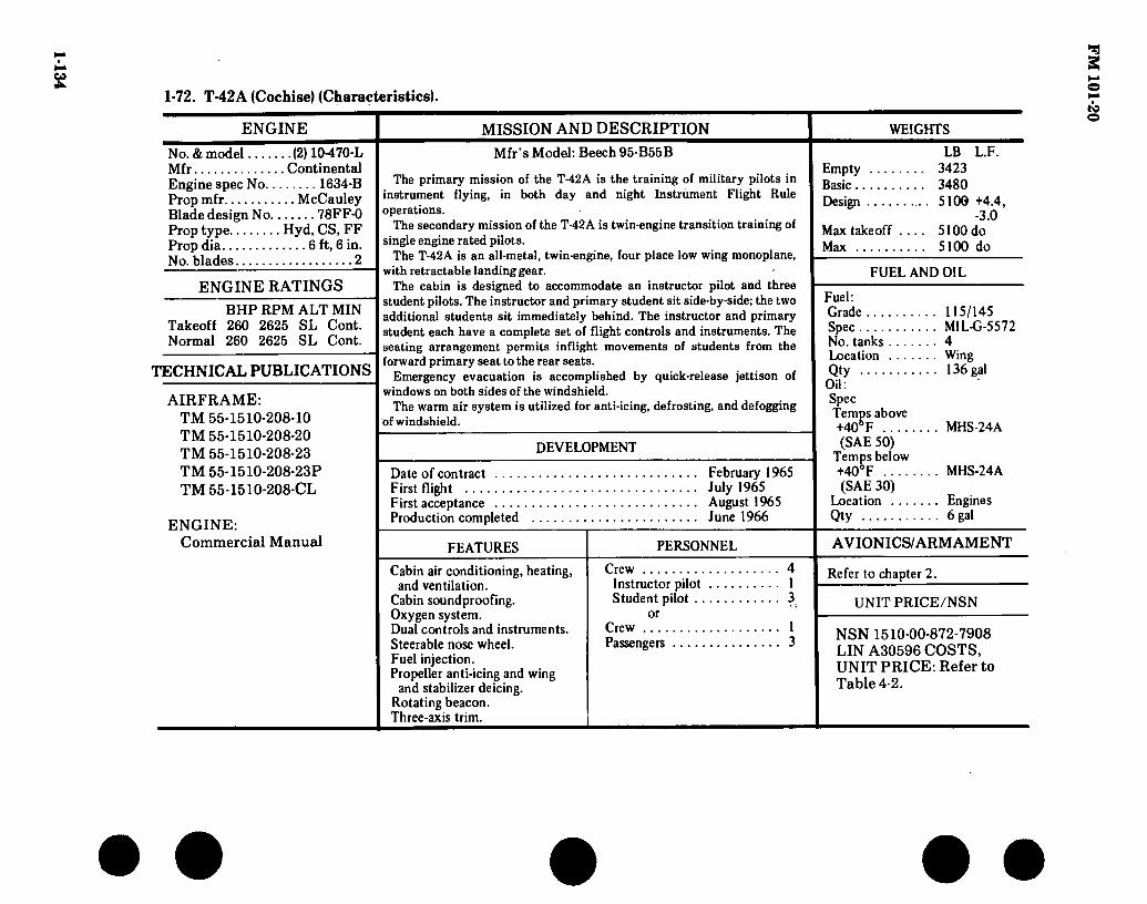
1-134
1-72. T-42A (Cochise) (Characteristics).
ENGINE MISSION AND DESCRIPTION WEIGHTS
No. & model (2) 10-470-L Mfr Continental Engine spec No 1634-B Prop mfr McCauley Blade design No 78FF-0 Prop type Hyd, CS, FF Prop dia 6 ft, 6 in. No. blades 2
ENGINE RATINGS BHP RPM ALT MIN
Takeoff 260 2625 SL Cont. Normal 260 2625 SL Cont.
TECHNICAL PUBLICATIONS
AIRFRAME: TM 55-1510-208-10 TM 55-1510-208-20 TM 55-1510-208-23 TM 55-1510-208-23P TM 55-1510-208-CL
ENGINE: Commercial Manual
Mfr’s Model: Beech 95-B55B
The primary mission of the T-42A is the training of military pilots in instrument flying, in both day and night Instrument Flight Rule operations.
The secondary mission of the T-42A is twin-engine transition training of single engine rated pilots.
The T-42A is an all-metal, twin-engine, four place low wing monoplane, with retractable landing gear.
The cabin is designed to accommodate an instructor pilot and three student pilots. The instructor and primary student sit side-by-side; the two additional students sit immediately behind. The instructor and primary student each have a complete set of flight controls and instruments. The seating arrangement permits inflight movements of students from the forward primary seat to the rear seats.
Emergency evacuation is accomplished by quick-release jettison of windows on both sides of the windshield.
The warm air system is utilized for anti-icing, defrosting, and defogging of windshield.
LB L.F. Empty 3423 Basic 3480 Design 5100 +4.4,
-3.0 Max takeoff .... 5100 do Max 5100 do
FUEL AND OIL
DEVELOPMENT
Date of contract .... First flight First acceptance .... Production completed
February 1965 July 1965 August 1965 June 1966
Fuel: Grade 115/145 Spec MIL-G-5572 No. tanks 4 Location Wing Qty 136 gal Oil: Spec Temps above +40° F MHS-24A (SAE 50)
Temps below +40° F MHS-24A (SAE 30)
Location Engines Qty 6 gal
FEATURES
Cabin air conditioning, heating, and ventilation.
Cabin soundproofing. Oxygen system. Dual controls and instruments. Steerable nose wheel. Fuel injection. Propeller anti-icing and wing
and stabilizer deicing. Rotating beacon. Three-axis trim.
PERSONNEL AVIONICS/ARMAMENT
Crew Instructor pilot Student pilot ..
or Crew .... Passengers
4 1 3
1 3
Refer to chapter 2.
UNIT PRICE/NSN
NSN 1510-00-872-7908 LIN A30596 COSTS, UNIT PRICE: Refer to Table 4-2.
FM
101-20

FM 101-20
1-73. Loading and Performance — Typical Mission, T-42A (Cochise).
TAKEOFF LOADING CONDITIONS
Takeoff weight Fuel Payload Wing loading Stall speed-i/ Stall speed-2/ Takeoff run at SL ... Takeoff run to clear 50 ft Max speed SL Rate climb SL Time SL to 10,000 ft Service ceiling (100 FPM)
BASIC MISSION
(lb) . . . (lb) . . . (lb) . . . (lbs/sq ft) (kn) . . . (kn) . . . (ft) . . . (ft) . . . (kn) . . . (fpm) • • (min) . . (ft) . . .
5,100 816
25.5 68
76.5 910
1,255 205
1,670 8
19,700
LANDING WEIGHT
(10% Fuel) 4,333
Fuel Ground roll at SL Landing distance to clear 50 ft obstacle
(lb)
(ft) (ft)
85 805
1,580
-!/ Zero thrust, flaps 28°, and gear down -2/ Power OFF, flaps up, and gear up
Source: TSARCOM-DRSTS-WP
1-135

FM 101-20
0 BB
Figure 1-49. U-8F (Seminole)
1-136

• 45 FT 10-1/2 IN.-
7 FT 9 IN
12 FT 9 N.
DIMENSIONS
17 R 2-3/4 IN.
33 FT 4 IN
i
Wing: Span 45 Ft. 10-1/2 In, Incidence (root) 4°, 48 min Incidence (tip) 0.0° Dihedral 7° Sweepback:
Outer panel 25 percent chord 0.0°
Center section 100 percent chord 0.0°
Length 33 Ft. 4 In. Height 14 Ft. 2 In. Tread 12 Ft. 9 In. Prop gnd
clearance 10-1/2 In.
□an
12 FT 3-1/2 IN.
14 FT 2 IN.
S FT 9 IN
Figure 1-50. Principal Dimensions, U-8F (Seminole)
1-137
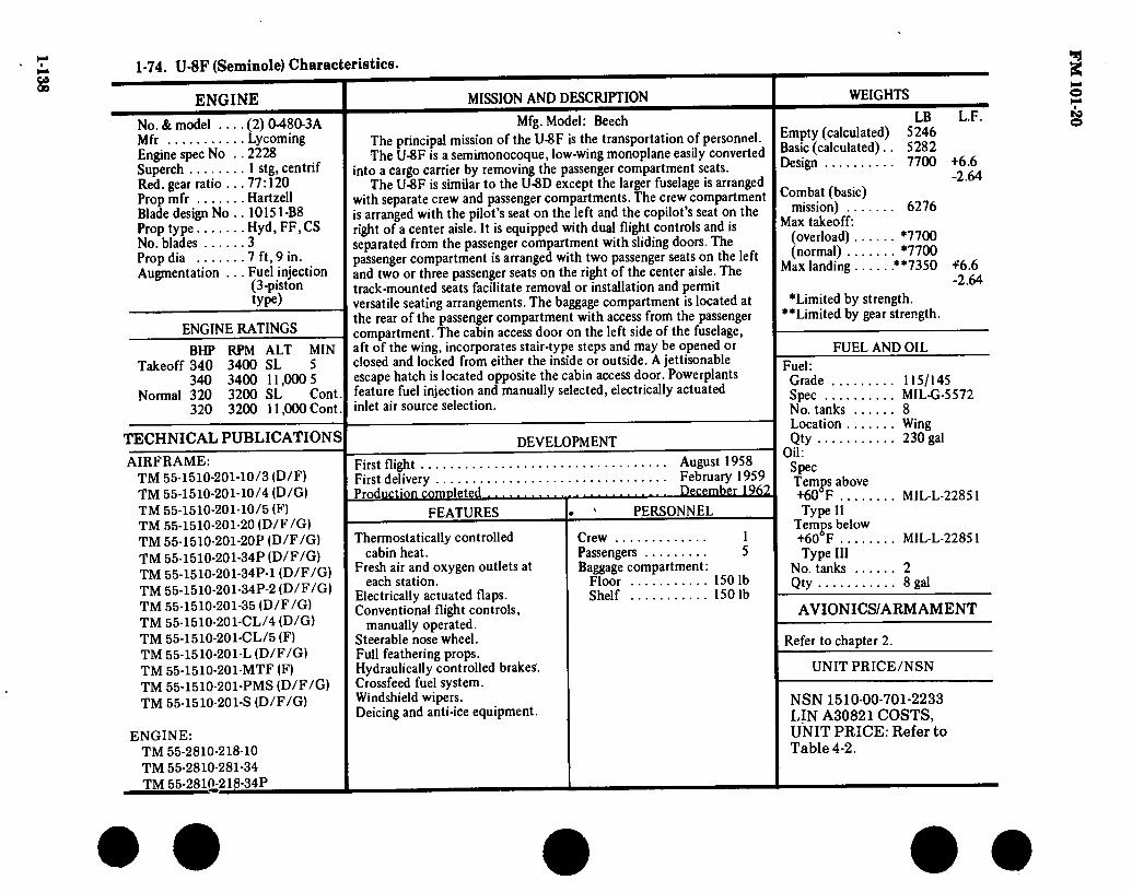
1-138
1-74. U-8F (Seminole) Characteristics.
ENGINE MISSION AND DESCRIPTION WEIGHTS
No. & model .... (2) 0480-3A Mfr Lycoming Engine spec No .. 2228 Superch 1 stg, centrif Red. gear ratio ... 77:120 Prop mfr Hartzell Blade design No .. 10151-B8 Prop type Hyd, FF, CS No. blades 3 Prop dia 7 ft, 9 in. Augmentation ... Fuel injection
(3-piston type)
ENGINE RATINGS
BHP RPM ALT MIN Takeoff 340 3400 SL 5
340 3400 11,000 5 Normal 320 3200 SL Cont.
320 3200 11,000 Cont.
TECHNICAL PUBLICATIONS
AIRFRAME: TM 55-1510-201 TM 55-1510-201- TM 55-1510-201 TM 55-1510-201 TM 55-1510-201 TM 55-1510-201 TM 55-1510-201 TM 55-1510-201 TM 55-1510-201 TM 55-1510-201 TM 55-1510-201 TM 55-1510-201 TM 55-1510-201 TM 55-1510-201 TM 55-1510-201
10/3 (D/F) 10/4 (D/G)
■10/5 (F) -20 (D/F/G) -20P (D/F/G) -34P (D/F/G) -34P-1 (D/F/G) -34P-2 (D/F/G) -35 (D/F/G) -CL/4 (D/G) -CL/5 (F) -L (D/F/G) -MTF (F) -PMS (D/F/G) -S (D/F/G)
ENGINE: TM 55-2810-218-10 TM 55-2810-281-34 TM 55-2810-218-34P
Mfg. Model: Beech
The principal mission of the U-8F is the transportation of personnel. The U-8F is a semimonocoque, low-wing monoplane easily converted
into a cargo carrier by removing the passenger compartment seats. The U-8F is similar to the U-8D except the larger fuselage is arranged
with separate crew and passenger compartments. The crew compartment is arranged with the pilot’s seat on the left and the copilot’s seat on the right of a center aisle. It is equipped with dual flight controls and is separated from the passenger compartment with sliding doors. The passenger compartment is arranged with two passenger seats on the left and two or three passenger seats on the right of the center aisle. The track-mounted seats facilitate removal or installation and permit versatile seating arrangements. The baggage compartment is located at the rear of the passenger compartment with access from the passenger compartment. The cabin access door on the left side of the fuselage, aft of the wing, incorporates stair-type steps and may be opened or closed and locked from either the inside or outside. A jettisonable escape hatch is located opposite the cabin access door. Powerplants feature fuel injection and manually selected, electrically actuated inlet air source selection.
DEVELOPMENT
First flight First delivery Production completed
FEATURES
Thermostatically controlled cabin heat.
Fresh air and oxygen outlets at each station.
Electrically actuated flaps. Conventional flight controls,
manually operated. Steerable nose wheel. Full feathering props. Hydraulically controlled brakes. Crossfeed fuel system. Windshield wipers. Deicing and anti-ice equipment.
August 1958 February 1959 December 1962
PERSONNEL
Crew 1 Passengers 5 Baggage compartment :
Floor 1501b Shelf 1501b
LB Empty (calculated) 5246 Basic (calculated).. 5282 Design 7700
Combat (basic) mission) 6276
Max takeoff: (overload) *7700 (normal) *7700
Max landing **7350
♦Limited by strength. ♦♦Limited by gear strength.
L.F.
+6.6 -2.64
+’6.6 -2.64
FUEL AND OIL
Fuel: Grade 115/145 Spec MIL-G-5572 No. tanks 8 Location Wing Qty 230 gal
Oil: Spec Temps above +60r MIL-L-22851 Type II
Temps below +60°F MIL-L-22851 Type III
No. tanks 2 Qty 8 gal
AVIONICS/ARMAMENT
Refer to chapter 2.
UNIT PRICE/NSN
NSN 1510-00-701-2233 LIN A30821 COSTS, UNIT PRICE: Refer to Table 4-2.
FM
101-20

• • • • • 1-75. Loading and Performance — Typical Mission, U-8F (Seminole).
CONDITIONS BASIC MISSION DESIGN MISSION NORMAL MISSION FERRY RANGE
co to
TAKEOFF WEIGHT (lb) .. Fuel at 6.0 lb/gal (grade 115/145) (lb) .. Payload (outbound) (lb).. Payload (inbound) (lb).. Wing loading (Ib/sq ft).. Stall speed (power off) (kn) .. Takeoff ground run at SLl/ (ft).. Takeoff to clear 50 ft 1/ (ft) .. Rate of climb at SL 2/ (fpm).. Rate of climb at SL (one engine out) (fpm).. Time: SL to 10,000 ft 2/ (min).. Time: SL to 20,000 ft 2/ (min) .. Service ceiling (100 fpm) 2/ (ft) .. Service ceiling (one engine out) 2/ (ft)..
COMBAT RANGE (nmi) .. Average cruising speed (kn).. Cruising altitude (ft).. Total mission time (hr) ..
COMBAT RADIUS V (nmi) .. Average cruising speed (kn) .. Cruising altitude (ft) • ■ Total mission time (hr)..
FIRST LANDING WEIGHT!/ (Ib) .. Ground roll at SL (ft).. Total from 50 ft (ft) ..
COMBAT WEIGHT 2/ (lb).. Combat altitude (ft) .. Combat speed .2/ (kn) .. Combat climb 2/ (fpm) .. Combat ceiling (500 fpm) 2/ (ft) .. Service ceiling (100 fpm) 2/ (ft) ., Service ceiling (one engine out) 2/ (ft).. Takeoff ground run at SL 1/ (ft)., Takeoff to dear 50 ft 1/ (ft) ., Max rate of climb at SL2/ (fpm) . Max speed at 12,000 ft 2/ (kn).. Basic speed at 5000 ft 2/ (kn).
LANDING WEIGHT (lb) . Ground roll at SL (ft) .. Total from 50 ft (ft) .,
77004/ 1380 778
None 27.5
70 1180 1560 1304
184 8.1
19.1 27.000
7650 1104
174 10.000
8.38 539 130
10,000 8.35 7054 1280 2025 6276
10,000 203
1685 27,200 32,500 15,550
760 1355 1825 207 193
5643 1280 1685
77004/ 1158 1000 None 27.5
70 1180 1560 1304
184 8.1
19.1 27,000
7650 898 135
10,000 6.67 434 130
10,000 6.83 7119 1310 2075 6138
10,000 203
1735 27,700 32.900 15.900
720 1300 1870 207 193
5632 1060 1660
77004/ 1380 778
None 27.5
70 1180 1560 1304
184 8.1
19.1 27.000
7650 883Í/ 171
10.000 5.23 415 5/ 172
10,000 4.97 7044 1285 2030 6266
10,000 203
1670 27,100 32,400 15,450
760 1360 1820 207 193
5643 1280 1685
69224/ 1380 None
24.7 68
1000 1720 1550 310 6.8
15.7 30.000 13,500
1220 127
10.000 9.61
5650 10,000
204 1935
29,800 34,600 17,500
600 1060 2100
208 194
5643 1065 1665
i/Maximum power - 3400 rpm. ¿/Normal power - 3200 rpm.

1-140 1-75. Loading Performance — Typical Mission, U-8F (Seminole) (Con’t).
3/ For RADIUS mission if radius is shown.
4/ Includes crew of 1 at 200 lb.
5/ 65-percent normal power used for cruise »
Performance Basis:
a. Data source: Contractor’s flight test.
b. Performance is based on powers shown.
• • • • • F
M 101-20
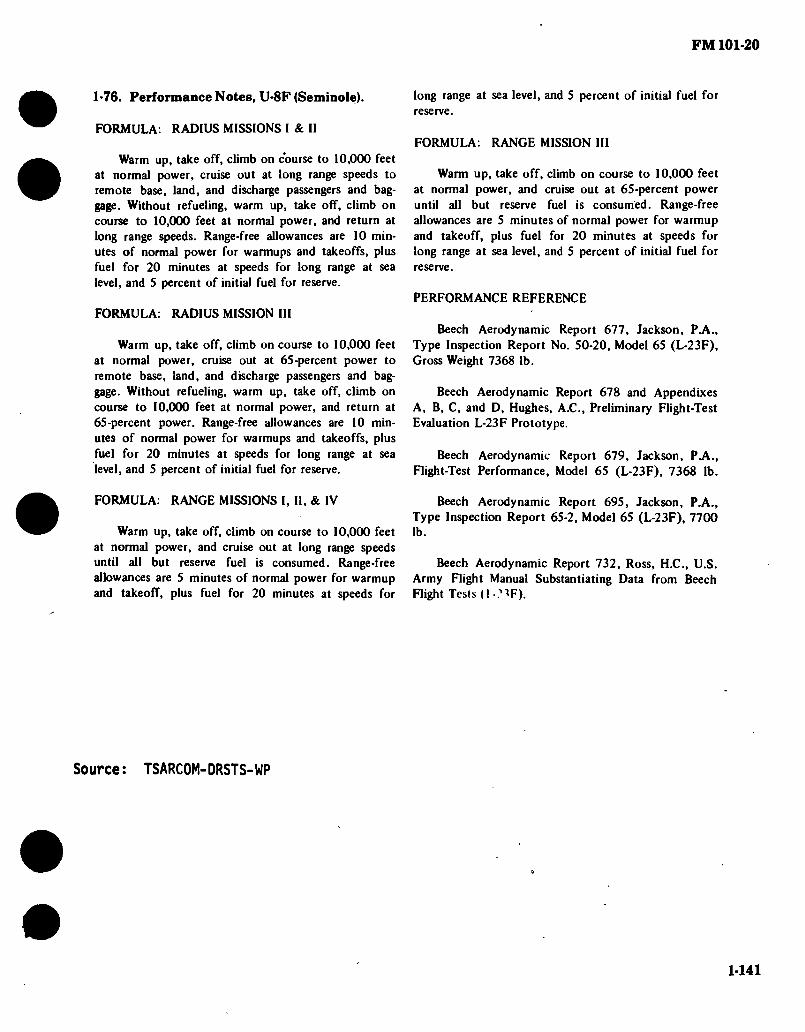
FM 101-20
1-76. Performance Notes, U-8F (Seminole).
FORMULA: RADIUS MISSIONS I & II
Warm up, take off, climb on course to 10,000 feet at normal power, cruise out at long range speeds to remote base, land, and discharge passengers and bag- gage. Without refueling, warm up, take off, climb on course to 10,000 feet at normal power, and return at long range speeds. Range-free allowances are 10 min- utes of normal power for warmups and takeoffs, plus fuel for 20 minutes at speeds for long range at sea level, and S percent of initial fuel for reserve.
FORMULA: RADIUS MISSION III
Warm up, take off, climb on course to 10,000 feet at normal power, cruise out at 65-percent power to remote base, land, and discharge passengers and bag- gage. Without refueling, warm up, take off, climb on course to 10,000 feet at normal power, and return at 65-percent power. Range-free allowances are 10 min- utes of normal power for warmups and takeoffs, plus fuel for 20 minutes at speeds for long range at sea level, and 5 percent of initial fuel for reserve.
FORMULA: RANGE MISSIONS I, II, & IV
Warm up, take off, climb on course to 10,000 feet at normal power, and cruise out at long range speeds until all but reserve fuel is consumed. Range-free allowances are 5 minutes of normal power for warmup and takeoff, plus fuel for 20 minutes at speeds for
long range at sea level, and 5 percent of initial fuel for reserve.
FORMULA: RANGE MISSION III
Warm up, take off, climb on course to 10,000 feet at normal power, and cruise out at 65-percent power until all but reserve fuel is consumed. Range-free allowances are 5 minutes of normal power for warmup and takeoff, plus fuel for 20 minutes at speeds for long range at sea level, and 5 percent of initial fuel for reserve.
PERFORMANCE REFERENCE
Beech Aerodynamic Report 677, Jackson, P.A., Type Inspection Report No. 50-20, Model 65 (L-23F), Gross Weight 7368 lb.
Beech Aerodynamic Report 678 and Appendixes A, B, C, and D, Hughes, A.C., Preliminary Flight-Test Evaluation L-23F Prototype.
Beech Aerodynamic Report 679, Jackson, PA., Flight-Test Performance, Model 65 (L-23F), 7368 lb.
Beech Aerodynamic Report 695, Jackson, P.A., Type Inspection Report 65-2, Model 65 (L-23F), 7700 lb.
Beech Aerodynamic Report 732, Ross, H.C., U.S. Army Flight Manual Substantiating Data from Beech Flight Tesis (I -.^F).
Source : TSARCOM-DRSTS-WP
1-141

FM 101-20
osa
Figure 1-51. U-10A (Helio-Courier)
1-142

FM 101-20
39 FT
4 FT 8 IN
9 FT DIMENSIONS
15 FT Wing: Span 39 Ft. Incidence 3° Dihedral Io
Sweepback (LE) outer panel 25 percent chord. 0.0°
Sweepback (LE) outer section 100 percent chord 0.0°
Length 30 Ft. 3-1/2 In Height 8 Ft. 10 In Tread 9 Ft Prop gnd
clearance 1 Ft. 8-1/2 In
0= FT 10 IN
□ o on 1 FT 8-1/2 IN
FT T»
Figure 1-52. Principal Dimensions, U-10A (Helio-Courier)
1-143

1-144 1-77. U-lOA (Helio-Courier) Characteristics.
ENGINE
No. & model (1)G0480- G1D6
Engine spec No ... .2227B Superch NA Red. gear ratio 0.641 (77:120) Prop mfr Hartzell Blade design No... .B3Z20-1/
10151C-5
Prop type Hydraulic, constant speed
No. blades 3 Prop dia 8 ft Prop type certificate No P-907-10
ENGINE RATINGS
BHP RPM Takeoff 295 3400 Normal 280 2750
TECHNICAL PUBLICATIONS
AIRFRAME: Commercial Manuals
(Contractor Supported)
ENGINE:
Commercial Manual
MISSION AND DESCRIPTION WEIGHTS
Mfr’s Model: Helio-Courier
Basic mission assignments of the U-10A aircraft include courier, observation, cargo carrying, parachute delivery and small groups, radio relay for extended periods of time, evacuation, and utility transport.
The U-10A is a versatile air vehicle in the STOL category specifically designed to utilize small, rough, and unprepared fields and offering a maximum of protection for pilot and crew. Adaptability to floats and skis enables the airplane to operate on water and snow.
The U-10A is an all-metal, high-wing, conventional-geared, four- place aircraft. The aerodynamic characteristics feature such items as long-span, high-lift type slotted flaps, and full-span leading edge slots. Lateral control is obtained by short-span, Frise-type, balanced ailerons which are operated in conjunction with leading edge spoilers. Ailerons alone are used for lateral control at higher speed. The airplane has an all-movable, slab-type, horizontal stabilizer with antibalance tab and a large vertical stabilizer and rudder.
The U-10A is powered by a six-cylinder engine splined to a three- bladed propeller with a constant-speed control and spinner to aid engine cooling.
PERSONNEL
Crew (normal) (pilot, copilot) 2
Passengers 2
FEATURES
Adaptable to floats & skis STOL type aircraft
LB Empty 2249 Max takeoff (normal) .... 3000 Max takeoff (overload) ... 3920
FUEL AND OIL
Fuel: Grade 115/145 Spec MIL-GT-5572 No. tanks: Wing, left (1) 30 gal Wing, right (1) 30 gal Qty 60 gal
OU: Spec Temps above +30® F MIL-L-22851 Type II
Temps below +30°F MIL-L-22851 Type III
No. tanks 1 Location Engine sump Qty 2-1/2 gal
AVIONICS/ARM AMENT
Refer to chapter 2.
UNIT PRICE/NSN
NSN 1510-00-964-9780 LIN A30971 UNIT PRICE: Refer to Table 4-2.
• • • • • F
M 101-20

FM 101-20
1-78. Loading and Performance — Typical Mission, U-10A (Helio Courier).
CONDITIONS BASIC MISSION
Max speed at SL
Max speed, 5000 ft
Min speed, power off, 40-deg flaps
Performance cruise at 6000 ft, 74-percent power, 2750 rpm
Range at 139 kn
Extended range cruise at 10,000 ft, 49-percent power, 2200 rpm
Range at 121 kn
Max endurance at 5000 ft, 29-percent power, 75 in TAS
Service ceiling ( 100 fpm R/C)
Takeoff data at SL, 0 wing, 25-deg flaps, paved runway: Takeoff weight
Ground roll
Total distance over 50-ft obstacle
Landing data at SL, 0 wind, 40-deg flaps, paved runway: Ground roll
Total distance over 50-ft obstacle
(kn)
(kn)
(kn)
(kn)
(nmi)
(kn)
(nmi)
(hr)
(ft)
(lb)
(ft)
(ft)
- (ft)
(ft)
145
142
42
139
436 (no reserve)
121
700 (no reserve)
9.14 (no reserve)
22,000
3000
290
500
180
495
Source: TSARCOM-DRSTS-WP
1-145

FM 101-20
Figure 1-53. U-21 and RU-21 (UTE) (Paint Scheme Difference)
1-146
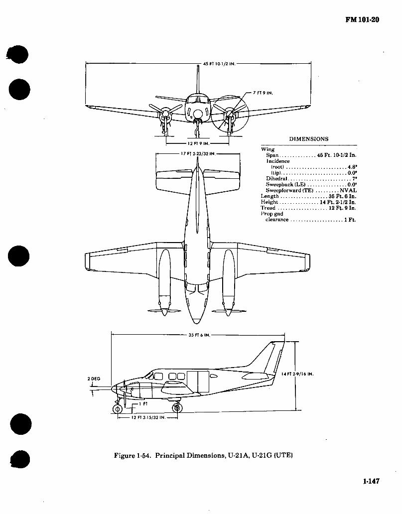
FM 101-20
45 FT 101/2 IN.
7 FT 9 IN
DIMENSIONS 12 FT 9 IN.
17 FT 2-23/32 IN - Wing
Span 45 Ft. 10-1/2 In. Incidence
(root) 4.8“ (tip) 0.0°
Dihedral 7° Sweepback (LE) 0.0” Sweepforward (TE) NVAL
Length 35 Ft. 6 In. Height 14 Ft. 2-1/2 In. Tread 12 Ft. 9 In. I’rop gnd
clearance 1 Ft.
n 1 A
35 FT 6 IN.
«O DO o> 2 DEG
1 FT
14 FT 2-9/16 IN.
12 FT 3-15/32 IN
Figure 1-54. Principal Dimensions, U-21A, U-21G (UTE)
1-147

FM 101-20
17’ 2.72”-
:
50’ 10.5”
7’9
12' 9”
35' 6"
FS30 FS49
FS160
14'2.56
5 i'sg'iy' _1 12
AV 111172 -12’ 3.47"
Figure 1-55. Three View Drawing and Dimensions (RU-21A)
1-148

1-149 • •
1-79. U-21A and RU-21A (UTE) Characteristics.
ENGINE
No. & model .... (2) T74-CP-700 (PT6A-20)
Mfr UACL Type Turboprop Prop mfr Hartzell Prop type Hyd, CS, FF No. blades 3 Prop dia 7 ft. 9 in.
ENGINE RATINGS
Takeoff SHP 550 ALT SL
TECHNICAL PUBLICATIONS
AIRFRAME: TM 55-1510- TM 55-1510- TM 55-1510- TM 55-1510- TM 55-1510- TM 55-1510- TM 55-1510- TM 55-1510 TM 55-1510 TM 55-1510 TM 55-1510 TM 55-1510
200-CL 200-PM •200-PMD 200-MTF 200-S
■209-L •209-CL ■209-CL-l -209-10 -209-10-1 -209-23-1, -2 -209-23P-1, P-2
ENGINE: TM 55-2840-232-23P TM 55-2840-232-24 TM 55-2840-120 (DMWR)
MISSION AND DESCRIPTION
Mfr’s Model: Beech Aircraft Corporation 65-A90-1
The U-21A is an off-the-shelf utility aircraft. The first production aircraft was tested by USATECOM for confirmation.
The U-21 A is an unpressurized, low wing, all-metal construction aircraft of versatile design with an all-weather capability. The primary mission of the U-21 A is to perform utility services in the combat zone, support commanders and their staff in command and ■ control, adminstration, liaison and aeromedical evacuation. The basic version of the aircraft is configured for troop transport; however, alternate configurations are available for service as air ambulance, staff transport, or air cargo transport.
DEVELOPMENT
Date of contract 30 September 1966 Contracting agency AVSCOM No. of test aircraft 3 First flight (scheduled) March 1967 Completion of test and evaluation July 1967 Contract delivery schedule 2 April 1967
23 May 1967 23 June 1967
FEATURES
Cabin heating and ventilating system.
Deicing and anti-icing system. Rotating beacon light. Steerable nose wheel. Controllable pitch, full
feathering, and reversible props.
PERSONNEL
Pilot 1 I/Passengers 6
or 2/Troops 10
or Litter patients ••. - 3
plus Ambulatory patients 3
plus Attendant 1
RU-21A Pilot Co-Pilot Equip. Operators
WEIGHTS LB
Empty 5401 Gross takeoff 9650 Gross landing 9168 Cargo capacity 3000
FUEL AND OIL
Fuel: Grade ... Spec No. tanks Location Qty Location Qty ....
Oil: Spec Temps above -40°F
Temps below -40°F
No. tanks ... Location ... Qty
JP4/5 MIL-T-5624 10 (8) wing 256 gal (2) Nacelle 114 gal
MILL-23699
MILL-7808 2 Nacelle 23 gal each
tank
AVIONICS/ARMAAŒNT
Refer to chapter 2.
UNIT PRICE/NSN
U-21A NSN 1510-00-933-8223 LIN A30946 UNIT PRICE: Refer to Table 4-2
RU-21A NSN 1510-00-587-3375 LIN A30582 COSTS, $587,004
Note: i/Normal seats 1/Combat - equipped
RU-21 A: U-21 A Modified for installation of special mission EW equipment.
FM
101-20

FM 101-20
1-80. Performance — Typical Mission, U-21A (UTE).
Payload (lb) .
Range (nmi)
Cruise speed 2^ (kn) .
Max speed (kn) .
Min takeoff distance (ft) .
Min landing distance (ft) .
Rate of climb (1 engine) (fpm) .
Service ceiling (2 engines) .... (ft) .
Service ceiling (1 engine) .... (ft) .
2000 V
1249
180
230
1000
800
350
25,000
10,000
V 3000 lb with fuel trade off.
Vjrue airspeed at normal rated power.
Source: TSARCOM-DRSTS-WP
1-150
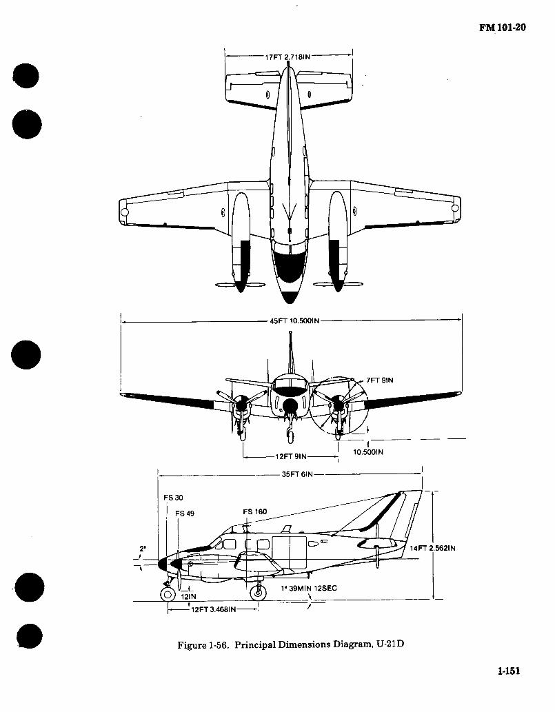
FM 101-20
17FT 2.7181 N
S) r\ r\ ) \/
45 FT 10.5001 N
7FT9IN
10.5001 N 12FT9IN
35 FT 6IN
FS 30
FS 160 FS 49
i: a □ L ■ v. 14FT 2.562IN
1° 39MIN 12SEC \
CS V OJ 12IN
12FT 3.468IN
Figure 1-56. Principal Dimensions Diagram, U-21D
1-151

1-152
1-81. RU-21D (UTE) Characteristics.
ENGINE MISSION AND DESCRIPTION WEIGHT
No. & model (2) T74-CP-700 (PT6A-20)
Mfr UACL Type Turboprop Prop mfr Hartzell Prop type Hyd, CS, FF No. blades 3 Prop dia 7 ft. 9 in.
Mfr’s Model: Beech Aircraft Corporation 65-A90-1
The U-21D is a unpressurized, low wing, all-metal construction aircraft of versatile design with an all-weather capability. The primary mission of the U-21D is to perform utility missions in the combat zone.
ENGINE RATINGS DEVELOPMENT
Takeoff SHP 550 ALT SL
TECHNfCAL PUBLICATIONS
AIRFRAME: TM 55-1510 TM 55-1510 TM 55-1510' TM 55-1510- TM 55-1510 TM 55-1510 TM 55-1510 TM 55-1510 TM 55-1510 TM 55-1510
200-PM 200-PMD 200-MTF 200-S 209-CL-l 209-10-1 209-23-1 209-23-2 209-23P-1 209-23P-2
U-21D Date of contract 2 FEB 68 Contracting agency AVSCOM No. of test aircraft — First flight (scheduled) MAY 68 Completion of test and evaluation ... — Contract delivery schedule JUL 68
OCT 68
FEATURES
ENGINE: TM 55-2840-232-23P TM 55-2840-232-24 DMWR 55-2840-120
Cabin heating and ventilating system.
Deicing and anti-icing system. Rotating beacon light. Steerable nose wheel. Controllable pitch, full
feathering, and reversible props.
PERSONNEL
Pilot ... Co-Pilot
LB Empty (wet) 6497 Gross takeoff 9650 Gross landing 9168 Cargo capacity 3000
FUEL AND OIL
Fuel: Grade JP4/5 Spec MIL-T-5624 No. tanks 10 Location (8) wing Qty 256 gal Location (2) Nacelle Qty 114 gal
Oil: Spec Temps above 40°F MIL-L-23699 Temps below 40op MIL-L-7808
No. tanks 2 Location Nacelle Qty 2.3 gal each
tank
AVIONICS/ARMAMENT
Refer to chapter 2.
UNIT PRICE/NSN
NSN 1500-00-804-3641 LIN A30585 UNIT PRICE: Refer to Table 4-2.
FM
101-20

FM 101-20
1-82. Performance — Typical Mission, RU-21D (UTE).
Payload (lb)
Range (nmi)
Cruise speed 2/ (kn)
Max speed (kn)
Min takeoff distance (ft)
Min landing distance (ft)
Rate of climb (1 engine) (fpm)
Service ceiling (2 engines) (ft)
Service ceiling (1 engine) (ft)
1,7671/
800
176
230
1,700
1,280
4 0
25,750
9,100
_l/Mission equipment and two operators.
_2/True airspeed at normal rated power.
Source: TSARCOM-DRCPM-AEL
1-153

FM 101-20
7.45 IN
y
b
) U
22 FT 4.6 IN
DIMENSIONS
Wing: Span 45 Ft. 10.5 In. Incidence
(root) 4.8° (tip) 1.0°
Dihedral 7° Sweepback (LE) 0.0° Sweepforward (TE) NVAL
Length 39 Ft. 11.36 In. Height 15 Ft. 4.25 In. Tread 13 Ft. Prop gnd
clearance 1 Ft. 1 In.
45 FT 10.5 IN
7 FT 6 IN DIA.
a
13 FT
39 FT 11.36 IN
SO o; o o o o o
13.50 I
15 FT 4 25 IN
IN
X FT 11 IN *4
Figure 1-57. Principal Dimensions, U-21F (UTE)
1-154

1-155
t
1-83. U-21F (UTE) Characteristics.
No. & model Mfr Type Prop mfr ... Prop type .. No. blades.. Prop dia ...
ENGINE MISSION AND DESCRIPTION
(2)PT6A-28 UACL Turboprop
Mfr’s Model: Beech Aircraft Corporation A100
The U-21F is an off-the-shelf utility aircraft. Hartzell Hyd, CS, FF 4 7 ft. 6 in.
The U-21F is a pressurized, low wing, all-metal construction aircraft of versatile design with an all-weather capability. The primary mission of the U-21F is to transport high ranking military and government officials.
ENGINE RATINGS
Takeoff SHP 680 ALT SL DEVELOPMENT
TECHNICAL PUBLICATIONS
Commercial Manuals (Contractor Supported)
Date of contract Contracting agency No. of test aircraft First flight (scheduled) Completion of test and evaluation Contract delivery schedule
30 JUN71 AVSCOM
MAY 71
30JUL71 30 AUG 71
FEATURES
Cabin heating and ventilating system.
Deicing and anti-icing system. Rotating beacon light. Steerable nose wheel. Controllable pitch, full
feathering, and reversible props.
Pressurized cabin. Air conditioning.
PERSONNEL
Pilot 1 Co-Pilot 1 Passengers 7
WEIGHTS
LB Empty (wet) 6790 Gross takeoff 11,500 Gross landing 11,210
FUEL AND OIL
Fuel: Grade Spec No. tanks ... Location .... Qty Location .... Qty Location ....
Qty Oil:
Spec Temps above -40°F
Temps below -40°F
No. tanks ... Location .... Qty
AVIONICS/ARMAMENT
Refer to chapter 2.
UNIT PRICE/NSN
NSN 1510-00-169-0295 LIN A30951 UNIT PRICE: Refer to
JP4/5 MIL-T-5624 14 10 wing 274 gal (2) Nacelle 114gal (2)Center Section 82 gal
MILL-23699
MILL-7808 2 Nacelle 2.3 gal each tank
Table 4-2.
FM
101-20

FM 101-20
1-84. Performance — Typical Mission, U-21F (UTE).
Payload
Range
Cruise speed 2J.
Max speed
Min takeoff distance ....
Min landing distance ....
Rate of climb (1 engine) .
Service ceiling (2 engines)
Service ceiling (1 engine) .
. .(lb)
. (nmi)
. (kn)
. (kn)
..(ft)
...(ft)
(fpm)
..(ft)
..(ft)
1,4001/
1,000
236
270
1,855
866
452
24,850
9,300
-1/3000 lb with fuel trade off.
-2/True airspeed at normal rated power.
Source: TSARCOM-DRSTS-WP
1-156

FM 101-20
17 FT 2-23/32 IN
r\
DIMENSIONS
Wing Span ,45 Ft. 10-1/2 In. Incidence
(root) 4.8° (tip) 0.0° •
Dihedral 7° Sweepback (LE) 0.0° Sweepforward (TE) NVAL Length 35 Ft. 6 In. Height 14 Ft. 2-1/2 In.' Tread 12 Ft. 9 In. Propgnd
clearance 1 Ft.
45 FT 10-1/2 IN
7FT9IN
FT
U FT 2-9/1« IN
35 FT « IN
FS 30
FS 49 FS 160
c: Q
MIN
|—1-12 FT 3-15/32 IN —-j
Figure 1-58. Principal Dimensions, RU-21B and RU-21C (UTE)
1-157

1-158 1-85. RU-21B and RU-21C (UTE) Characteristics.
No. & model
Mfr
ENGINE MISSION AND DESCRIPTION
(2) T74-CP-702 Mfr’s Model : Beech Aircraft 65-A90-2 (RU-21B) (PT6A-29) 65-A90-3 (RU-21C) UACL
Type .... Prop mfr . Prop type No. blades
Turboprop Hartzell'
Hyd, CS, FF 3
The RU-21 B & C models are modified U-21A to carry special ASA mission equipment. They have engines with greater SHP, are beefed up to accomodate higher gross weight, and are equipped with dual wheel landing gears.
Prop dia 7 ft. 9 in.
ENGINE RATINGS
Takeoff SHP 620 ALT SL
TECHNICAL PUBLICATIONS
DEVELOPMENT
Date of contract, Amendment Contracting agency No. of test aircraft First Flight (Scheduled)
AIRFRAME: TM 55-1510-214-10 TM 55-1510-214-CL TM 55-1510-214-23 TM 55-1510-209-23P-1, P-2 TM 55-1510-200-PM TM 55-Í510-200-PMD TM 55-1510-200-MTF TM 55-1510-200-S
Completion of Test and Evaluation
Contract Delivery Schedule
FEATURES
Cabin heating and ventilating system.
Pilot . Copilot
12 Jun 1967 AVSCOM 2 Aug 1968 Final test not completed (Est Apr 72)
PERSONNEL
ENGINE: TM 55-2840-232-24 TM 55-2840-232-23P
Deicing and anti-icing system. Rotating beacon light. Steerable nose wheel.
Mission Equipment Operator RU-2 IB RU-21C
Controllable pitch, full feathering, and reversible props.
Passengers
WEIGHTS
LB Empty RU-2 IB 5955
RU-21C 5907 Gross takeoff 10,900 Gross landing 10,900
FUEL AND OIL
Fuel: Grade JP4/5 Spec MIL-T-5624 B MODEL No. Tanks .... 12 Location (10) Wing Qty 290 gals Location (2)Nacelle Qty 106 gals
C MODEL 12
(8) wing 290 gals (2) Nacelle 106 gals
40oF(25°C) MIL-L-7808 40oF(25°C) MIL-L-23699 2 Nacelle 2.3 gal each tank
AVIOÑICS/ARMAMENT
Refer to chapter 2.
FLYAWAY COSTS/NSN
No. Tanks Location . Qty Location . Qty
Oil: Spec
Below ..
Above ..
No. tanks Location . Qty
LIN A30583 COSTS $1,257,811
RU-21C NSN 1510-00-878-4336 LIN A30584 COSTS $1,259,760
FM
101-20

FM 101-20
1-86. Performance — Typical Mission, RU-21B and RU-21C (UTE).
Payload
Range
Cruise speed
Max speed
Min takeoff distance ....
Min takeoff distance ....
Min landing distance ....
Min landing distance ....
Rate of climb (1 engine) .
Rate of climb (1 engine) .
Service ceiling (2 engines)
Service ceiling (1 engine)
.(lb)
. (nmi)
.. (kn)
.. (kn)
■ • (ft)
• ■ (ft)
■ • - (ft)
...(ft)
• (fpm)
• (fpm)
• ■ (ft)
..(ft)
1371 16S8
940 940
194
208
2860
2140
1750
1360
208
365
20,000
7,000
V _!/
-l/Mission Equipment
Source: TSARCOM-DRCPM-AEL
B Model C Model
B Model C Model
B Model
C Model
B Model
C Model
B Model
C Model
1-159

FM 101-20
DIMENSIONS
Wing Span 50 Ft. 11 In.
Incidence (root) 4.8" (tip) 0.0»
Dihedral 7° Sweepback (LE) 0.0" Sweepforward
(TE) NVAL Length 35 Ft. 26 In. Height 14 Ft. 2-1/2 In. Tread 12 Ft. 9 In. Prop gnd
clearance . 1 Ft.
17 FT 2.72 IN
50FT11 IN
7 FT. 9 IN
12 FT 9 IN.
35 FT 6 IN.
D 14 FT 2.56 IN 2
IN 12 1" 39 FT 12 IN
h T 12 FT 3.47 IN.— T
Figure 1-59. Principal Dimensions, RU-21H (Guardrail V)
1-160

1-161 • • • • •
1-87. RU-21H (Guardrail V) Characteristics.
ENGINE MISSION AND DESCRIPTION WEIGHTS
No. & model (2) T74-CP-700 (PT6A-20)
Mfr UACL Type Turboprop Prop mfr Hartzell Prop type Hyd, CS. FF No. blades 3 Prop dia 7 ft. 9 in.
ENGINE RATINGS
Takeoff SHP 550
The RU-21H is an unpressurized, all metal low wing aircraft I powered by two T74-CP-700 turboprop engines. Distinguish- ! able features of the acft are the slender, streamline engine nacelles, square-tipped tail services, and swept back vertical stabilizer with ventral fin. Vertically oriented antennas and tip pods are installed on the wings. Cabin entrance and egress is made through an air-stair type door on the left side of the fuse- lage. An escape hatch is also fitted in the top of the pilots com- partment. The primary missions of this acft are signal intelli- gence and electronic surv. Features include IR paint scheme.
ALT SL
TECHNICAL PUBLICATIONS
AIRFRAME: TM 55-1510-215-10-2 TM 55-1510-215-CL-2 TM 55-1510-215-23 TM 55-1510-215-23-1 TM 55-1510-215-23-2 TM 55-1510-209-23P-2, P-2 TM 55-1510-200-MTF TM 55-1510-200-PM TM 55-1510-200-PMD TM 55-1510-200-S
ENGINE: TM 55-2840-232-23P TM 55-2840-232-24
DEVELOPMENT
Date of contract 30 JUN 76 Contracting agency USAGE RCOM No. of test aircraft PIP First flight (scheduled) N/A Completion of test and evaluation SEP 78 Contract delivery schedule SEP 78 -FEB 80
FEATURES
Cabin heating and ventila- ting system.
Deicing and anti-icing system.
Rotating beacon light. Steerable nose wheel. Controllable pitch, full
feathering, and reversible props.
Capacitance Fuel Gaging System
PERSONNEL
Pilot ... CoPilot.
LBS. Basic 6480 Gross takeoff 10,200 Gross landing 9700 Mission Equip 1000
FUEL AND OIL Fuel:
Grade JP4/5 Spec MIL-T-5624 No. tanks 10 Location (8) wing Qty 256 gal Location (2) Nacelle Qty 114 gal
Oil: Spec Temps above 32°F MIL-L-23699 Temps below 32°F MIL-L-7808 No. tanks 2 Location Nacelle Qty 2.3 gal each tank
AVIONICS/ARMAMENT
Refer to chapter 2.
UNIT PRICE/NSN
NSN 1510-00-394-3320 LIN Z04570 UNIT PRICE: Refer to Table 4-2.
FM
101-20

FM 101-20
1-88. Performance — Typical Mission, RU-21H (UTE).
Payload (lb)
Range (nmi)
Cruise speed-2L/ (kn)
Max speed (kn)
Min takeoff distance (ft)
Min landing distance (ft)
Rate of climb (1 engine) (fpm)
Service ceiling (2 engines) (ft)
Service ceiling (1 engine) (ft)
1,767 X/
800
176
230
1,700
1,280
410
26,750
9,100
U Mission equipment and two operators. -¿/True airspeed at normal rated power.
Source: T SARCOM-DRCPM-AEL
1-162

Figure 1-60. U-21J (Typical)
1-163

FM 101*20 43 FT. 10 IN.
a 15 Ft. OIN.
D QOOOO O
1 14 IN o
? 15 Ft. 0 IN.
29.6 IN. ^
^==A
'
DIMENSIONS
Wing Span 54 Ft. 6 In. Length 43 Ft. 10 In. Height 15 Ft. 0 In. Tread 17 Ft. 2 In. Prod Grd
Clearance 1 Ft. 2.5 In.
18 FT. 5 IN
54 R. 6 IN.
8R. 2.5 IN. DIA
17 FT. 2 N.
1-164 Figure 1-61. U-21J (Typical)

1-165
• • • • • 1-89. RU-21J Characteristics.
ENGINE
No. and Model Mfr Type Prop Mfg Prop Type No. Blades Prop Día
(2) PT6A-41 UACL Turbo Prop ... Hartzell C5 3 8 Ft. 2Y2 In.
ENGINE RATINGS
TAKEOFF SHP 850 ALT SL
MISSION AND DESCRIPTION WEIGHTS
Mfg. Model: Beech Aircraft Corp A100-1
The U-21J, an off-the-shelf utility aircraft which is totally contractor supported.
The U-21J is an all metal twin turbo prop engine, fixed wing, pressurized cabin, passenger/cargo carrying air- craft. The aircraft is designed and equipped for flight operations under Instrument Flight Rule (IFR) condi- tions day or night into high density air traffic control zones and into known icing weather conditions. The primary mission of this aircraft is to perform utility and command liaison missions.
LOADING Empty Basic Design Combat
Clean Light Scout Heavy Scout Hog
Max. Takeoff Max. landing
FUEL AND OIL
LB.
Serial Numbers 71-21058 thru 71:21060.
TECHNICAL PUBLICATIONS
DEVELOPMENT Date of contract 1971 First flight (Similar aircraft) N/A First acft delivered July 1974
FEATURES PERSONNEL
AIRFRAME:
Commercial Manuals (Contractor Supported)
All Metal T-Tail Retractable Tricycle with
Dual Main Wheel Duel Side by Side Flight Controls
Crew
ENGINE:
Fuel: Grade JP 4/5 Spec MIL-T-5624 No. tanks 12 Location 10 Wing
2 Nacelle Qty 386 (544 w/
Aux Tanks) OU:
Spec MIL-L-23699 No. tanks 2 Location Nacelle Qty 3.5 Gal Each Tank
AVIONICS / ARMAMENT
Refer to chapter 2.
UNIT PRICE/NSN
NSN 1520-00-124-0914 LINZ04615 UNIT PRICE: Refer to Table 4-2.
FM
101-20

FM 101-20
1-90. Performance — Typical Mission, U-21J.
Payload (LB) Range (NMI) Cruise Speed (KN) Max Speed (KN) Min Takeoff Distance (FT) Min Landing Distance (FT) Rate of Climb (1 Eng) (FPM) Service Ceiling (2 Eng) (Ft) Service Ceiling (1 Eng) (Ft)
Source: TSARCOM DRCPM-AEL
1-166

FM 101-20
Wm
rM
« «k..*
4
Figure 1-62. UV-18A (Twin Otter)
1-167
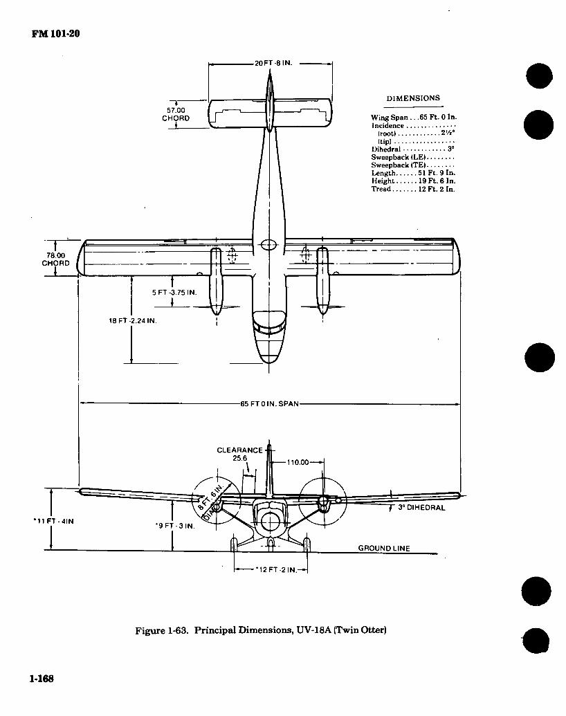
FM 101-20
20FT -8 IN.
DIMENSIONS
Wing Span .. .65 Ft. 0 In. Incidence
(root) Z'/i0
(tip) Dihedral 3° Sweepback (LE) Sweepback (TE) Length 51 Ft. 9 In. Height 19 Ft. 6 In. Tread 12 Ft. 2 In.
3 57.00
!£ CHORD
fv frffi 78.00 CHORD
\ I
Si
5 FT -3.75 IN.
I 18 FT -2.24 IN
3/ 65 FTO N.SPAN
CLEARANCE 25.6
110.00
r a» DIHEDRAL
$ 9 FT-3 IN.
GROUND LINE
12 FT -2 IN.
*11 FT-4IN
Figure 1-63. Principal Dimensions, UV-18A (Twin Otter)
1-168

1-169
» • • • 1-91. UV-18A (Charactersitcs).'
ENGINE MISSION AND DESCRIPTION WEIGHTS
No. and Model (2) PT6A-27 Mfr Canadian P&W Engine Spec. No 583 Prop mfg Hartzell Prop type C5 No. blades 3
ENGINE RATINGS
SHP Condition Take-off 620 ISA+180C Max Cruise 620 ISA-t-6°C
TECHNICAL PUBLICATIONS
AIRFRAME:
Commercial Manuals (Contractor Supported)
ENGINE: ‘
Commercial Manual
The aircraft with a crew of two is capable of carrying twenty passengers with baggage in the utility seating arrangement to provide command administrative, logistics and personnel flights from battalion headquar- ters to remote sites throughout western and northern Alaska on a year-round basis. With the utility seats folded a partial or full freight-carrying confíguration is available. With necessary adaptations, the aircraft may be used in an air ambulance, rescue, forrestry / pipeline patrol and air drops of personnel equipment and supplies missions.
CABIN VOLUME (USEABLE) BAGGAGE OOMPT-VOLUME-REAR BAGGAGE OOMPT-VOLUME-REAR
(MOD 6/1075) BAGGAGE OOMPT-VOLUME-FWD
384 CU FT 52 CU FT 88 CU FT
22 CU FT
DEVELOPMENT
Date of contract First flight (Similar aircraft) First acft delivered Dec 1976
FEATURES
All metal, high wing monoplane
Fixed tricycle landing gear
Conventional three control, dual side-by-side rudder pedal / control column combination
PERSONNEL
Crew Passengers
..2 20
LOADING LB. Empty Basic Design Combat
Clean Light Scout Heavy Scout Hog
Max. Takeoff 12,500 M{ix. Landing 12,300
(C) Calculated ♦For Basic Mission
FUEL AND OIL
Fuel: Grade JP4/5 Spec MIL-J-5624G No. Tanks 10 Location ... 8 Under Floor,
2 in Wing Qty 2608 Lbs.
Oil: Spec MIL-L-23699 No. Tanks 2 Location in Engines Qty---
AVIONICS/ARMAMENT
Refer to chapter 2.
UNIT PRICE/NSN
NSN 1510-01-011-1462 LIN A30989 COSTS UNIT PRICE: Refer to Table 4-2.
FM
101-20

FM 101-20
1-92. Performance — Typical Mission, UV-18A (Twin Otter).
Payload Range Cruise Speed Max Speed Min Takeoff Distance Min Landing Distance Rate of Climb (1 Engine)... Service Ceiling (2 Engines) Service Ceiling (1 Engine).
.. .(LB)
. (NMI) ..(KN) ..(KN) .. .(FT) • • .(FT) (FPM) .. .(FT) • • .(FT)
3003 1/ 400 181
1200 1050 340
26,700 11,600
_!/4083 Lb with fuel trade off.
Source: TSARCOM-DRSTS-WP
« 1-170

FM 101-20
CHAPTER 2
LOGISTICS AND MATERIAL
Section I. MAXIMUM ALLOWABLE OPERATING TIME (MAOT) (MAJOR COMPONENTS
2-1. Major Components.
This section was eliminated since the applicable Technical Manuals (TM’s) are now included in Chapter 1, Section IV, Standard Aircraft Characteristics. The TM is more current and in
more detail than FM 101-20. Refer to the characteristics pages of each individual aircraft in Section IV. The -20, Chapter 3 of the applicable TM lists all Maximum Allowable Operating Time (MAOT) and Time Between Overhaul (TBO).
Section II. AIRCRAFT EQUIPMENT
2-2. Avionics and Surveillance Equipment Con- figurations.*
The following avionics and surveillance con- figurations are typical and may vary depending on production run, changes incorporated through MWO action, and theater of operation in which the
aircraft is employed. The abbreviation CPO in this section is defined as “complete provisions only.” It indicates that power, space, weight and wiring have been incorporated and considered but the equipment has not been installed.
Source: CERCOM (DRSEL-MME-LAE)
* 2-1

FM 101-20
2-2. Avionics and Surveillance Equipment Configurations (Con’t).
The following configuration depicts a typically configured AH-1( ). The actual configuration may vary depending on pecular geographic requirements or changes incorporated through MWO action and special purpose alterations.
FUNCTION/TYPE NUMBER
INTERCOMM
C-161K )/AIC
C-6533/ARC
209-077-204-1
UHF/AM RADIO
AN/ARC-51BX consisting of:
C-6287/ARC-51BX
HD-615/ARC-51X
ID-1003/ARC
MT-2653/ARC
RT-742( )/ARC
AT-1108/ARC
NOMENCLATURE
Intercomm Control
Intercomm Control
ICS Filter
Radio Set
Control
Cool er
SWR Indicator
Mount
Receiver-Transmitter
VHF/UHF Antenna
CD
I I <
1
1
1
1
1
1
ll
a o
I 3T <
1
1
1
1
1
1
ll
o o oc OL
3C c
oo < o
ar
2-2
AH
-1S
(MO
DE
RN
IZE
D)

FM 101-20
2-2. Avionics and Surveillance Equipment Configurations (Con*t).
AH-K )
FUNCTION/TYPE NUMBER NOMENCLATURE
<3
O o
oo
I 3:
o o Û.
t/> I
<t
OO
o
oo r-
I oc <c
o LU hsl
Q O
I 3C <
AN/ARC-116( )
RT-1167/ARC-164(V)
AT-256A/ARC
HPF40-01T
Radio Set
Radio Set
UHF Antenna
UHF Hi Pass Filter
VHF/AM RADIO
AN/ARC-134 consisting of:
C-7197/ARC-134
Ml-37 91C/ARC-134
RT-857/ARC-134
AN/ARC-115( )
RT-1354/ARC-186(V)
AS-3204/ARC
AT-1108/ARC
BPF40-03P
Radio Set
Control
Mount
Recei ver-T ransmi tter
Radio Set
Radio Set
VHF Antenna
VHF/UHF Antenna
VHF Band Pass Filter
31
3,
VHF/FM RADIO
AN/ARC-54 consisting of:
C-3835/ARC-54
Radio Set
Control
2-3

FM 101-20
2-2. Avionics and Surveillance Equipment Configurations (Con’t).
AH-K )
FUNCTION/TYPE NUMBER
MT-1535/ARC-54
RT-348/ARC-54
AN/ARC-131 consisting of:
C-7088/ARC-131
MT-3664/ARC-131
RT-823/ARC-131
AS-2285/ARC
209-075-292-1
AN/ARC-114( )
AS-3205/ARC
209-077-202-3
LPF40-02B
SECURE VOICE
MD-736/A
MD-1101/A
MT-3802/ARC
C-8157/ARC
NOMENCLATURE
Mount
Receiver-Transmitter
Radio Set
Control
Mount
Recei ver-T ransmi tter
FM Comm Antenna
FM Homing Antenna
Radio Set
FM Homing Antenna
FM Comm Antenna Assy
FM Low Pass Filter
Signal Discriminator
Audio Threshold Device
Mount
Control-Indicator
o I
ni «£
41
4,
o o
CO
I
<c
o o o.
CO
I X <
CO c o
to
I X
2-4
AH
-1S
(MO
DE
RN
IZE
D)

FM 101-20
2-2. Avionics and Surveillance Equipment Configurations (Con’t).
AH-1( )
FUNCTION/TYPE NUMBER NOMENCLATURE
CD
□C
Q O
(/) I I <
o o Q£ Û.
00
I □c <c
CO c o
CO
I zc <c
Q LU hsl
Q O
31
Z-AHP
Z-AHQ
TSEC/KY-28
TSEC/KY-58
Remote Control Unit
Interface Adapter
Comm Security Set
Comm Security Set
3CP0
5CP0
3CP0
5CP0
3CP0
5CP0
3CP0
^PO
3CP0
JCP0
GYRO COMPASS
AN/ASN-43 consisting of:
CN-405/ASN
CN-998( )/ASN-43
T-eil/ASN
C-6347/ASN
Gyro Compass Set
Compensator
Directional Gyro
Compass Transmitter
Compass Control
ADF
AN/ARN-83 consisting of:
AS-1863/ARN-83
C-6899/ARN-83
MT-3605/ARN-83
R-l391/ARN-83
AN/ARN-89B consisting of:
AM-4859A/ARN-89
Direction Finder Set
Loop Antenna
Control
Mount
Receiver
Direction Finder Set
Amplifier
2-5
m

FM 101-20
2-2. Avionics and Surveillance Equipment Configurations (Con't).
AH-K )
FUNCTION/TYPE NUMBER
AS-2108A/ARN-89
C-7392A/ARN-89
R-1496A/ARN-89
209-030-133-7
V0R/MB/GS
AN/ARN-123(V)3 consisting of:
C-10048/ARN-123(V)
MT-4980/ARN-123(V)
R-2023/ARN-123(V)
AS-1304/ARN
AS-3188/ARN
AT-640( )/ARN
DOPPLER NAVIGATION
AN/ASN-128 consisting of:
CP-1252/ASN-128
CV-3338/ASN-128
RT-1193/ASN-128
NOMENCLATURE
Loop Antenna
Control
Receiver
Sense Antenna
Receiving Set
Control
Mount
Recei ver
VOR Antenna
GS Antenna
MB Antenna
Doppler Navigation Set
Computer-Display Unit
Signal Data Converter
Recei ver-T ransmi tter- Antenna
ID
I Z
o o £
</> I
2C C
o o oc ex.
co i
sc c
< o
CO
I £ <c
o UJ tsi
o o
tS)
I £
CP0
CP0
CP0
CP0
CP0
CP0
m
2-6 m

2-2. Avionics and Surveillance Equipment Configurations (Con’t). FM101-20
FUNCTION/TYPE NUMBER NOMENCLATURE
C9
I 3= C
CO r—
I :n <c
GO
I 31 <
CO
I c
RADAR ALTIMETER
AN/APN-209( )(V)1' consisting of:
AS-2595/APN-194(V)
RT-1115( )/APN-209(V)
Radar Altimeter Set
Antenna
Recei ver-T ransmi tter- Height Indicator
IDENTIFICATION
AN/APX-72 consisting of:
C-6280A(P)/APX
MT-3809/APX-72
RT-859( )/APX-72
MT-3513/APX
TS-1843( )/APX
AT-884( )/APX
AT-741B/A
C-10533/APX-100
MT-4811/APX-100
RT-1157( )/APX-100
Transponder Set
Control
Mount
Transponder
Mount (TS-1843)
Test Set
Antenna (Lower)
Antenna (Upper)
Control
lount (RT-1157)
Transponder
1
1
1
1
1
1
1
1
1
1*
1
1
1 1
1 1
1 1
1 1
1 1
1 1 1
1
1
1
1
2-7
AH
-IS
(MO
DE
RN
IZE
D)

FM 101-20
2-2. Avionics and Surveillance Equipment Configurations (Con’t).
AH-K )
FUNCTION/TYPE NUMBER
MT-3949A/U
KIT-1A/TSEC
RADAR WARNING
AN/APR-39(V)1 consisting of:
AS-2890/APR-39(V)
AS-2891/APR-39(V)
AS-2892/APR-39(V)
C-9326/APR-39(V)
CM-440/APR-39(V)
IP-1150/APR-39(V)
R-1838/APR-39(V)
NOMENCLATURE
Mount (KIT-1A)
IFF Computer
Radar Signal Detecting Set
Blade Antenna
Right Spiral Antenna (2 ea)
Left Spiral Antenna (2 ea)
Control
Comparator
Indicator
Receiver (2 ea)
o ■
IC «t
1
CPO
o o
«/> ' I «*
1
CPO
a o cc a.
co i
ni c
1
CPO
CPO
CPO
CPO
CPO
CPO
CPO
CPO
CO c o
CO
I □I c
1
CPO
CPO
CPO
CPO
CPO
CPO
CPO
CPO
1
CPO
.CPO
CPO
CPO
CPO
CPO
CPO
CPO
PROXIMITY WARNING .
YG-1054D1 consisting of:
10027834-101
JG1054-AA01
HG1001-AD01
Proximity Warning System
Antenna
Remote Indicator
Recei ver-T ransmi tter
2-8
AH
-1S
(MO
DE
RN
IZE
D)

FM 101-20
2-2. Avionics and Surveillance Equipment Configurations (Con’t).
AH-K )
FUNCTION/TYPE NUMBER
STABILIZATION
209-074-070-3
209-074-080-103
209-074-084-1
209-074-092-1
570-074-010-11
570-074-060-1
570-074-131-3
570-074-315-3
NOMENCLATURE
Control Panel
Sensor Amplifier
Control Panel
Armament Compensator
Sensor Amplifier
Control Panel
Pylon Compensator
Rate Gyro Sensor
to ■
:E ■t
a o
co i
a o QC Q.
lO I
JC c
CO c o
I/O
I c
a Lcl IVl
O o
«/> I
3C <C
COUNTERMEASURES
AN/ALQ-136(V)1 consisting of:
AS-3007/ALQ-136
RT-1149/ALQ-136
AN/ALQ-144(V)3 consisting of:
C-9576/ALQ-144
CY-7611/ALQ-144
T-l 360(V)1/ALQ*-144
Countermeasures Set
Antenna (2 ea)
Receiver-Transmi tter
Countermeasures Set
Operators Control Unit
Transit, Case
Transmitter
CP0
CP0
CP0
CP0
CP0
2-9
m

FM 101-20
2-2. Avionics and Surveillance Equipment Configurations (Con’t).
AH-K )
FUNCTION/TYPE NUMBER
LASER TRACKER
AN/AAS-32 consisting of:
C-9641/AAS-32
MX-9623/AAS-32
R-l960/AAS-32
POWER SOURCES
BB-649( )/A
PP-6508/U
PP-7274( )/A
PU-543( )/A
MISCELLANEOUS
AM-3209/ASN
CN-1314/A
CN-1497/A
ID-48/ARN
ID-250( )/ARN
ID-998/ASN
ID-2103/A
2-10
NOMENCLATURE
Airborne Laser Tracker Set
Control
Electronic Components Assy
Receiver-Tracker
Battery
Static Inverter
Static Inverter
Inverter
Servoampli fier
Displacement Gyro
Displacement Gyro
Dourse Indicator
ladio Magnetic Indicator
Radio Magnetic Indicator
Horz Situation Indicator
19
I X c
Q O
üO
I X c
Q O CC Q_
CO
I X <x.
CO
o
CO
I X
CPO
CPO
CPO
/
f
AH
-1S
(MO
DE
RN
IZE
D)

FM 101-20
2-2. Avionics and Surveillance Equipment Configurations (Con*t).
AH-K )
FUNCTION/TYPE NUMBER NOMENCLATURE
o i
:E
o o
to
I
Q o Q.
(/) I
:c .«t
oo c o
1/) I
<c
o ÜJ fvl »—^ z O' ÜJ o o s:
oo i □c
ID-2104/A
ID-2105/A
MC-1
TRU-2A/A
209-077-081-3
209-077-081-5
Attitude Direction Indicator
Radio Magnetic Indicator
Rate Gyro
Rate Gyro
HSI Display Control Panel
HSI Display Control Panel
’CP0
1
1
’CPO
1
1
3CP0
2-11

FM 101-20
2-2. Avionics and Surveillance Equipment Configurations (Con’t).
NOTES:
1. 2.
3.
4.
5.
6. 7.
8.
The AT-1108 is used with both the UHF/AM and VHF/AM systems. The AN/ARC-116 was installed in lieu of the RT-1167/ARC-164 in a few early FY 76 aircraft. The AN/ARC-115 and RT-1354/ARC-186 are interchangeable; therefore, either may be installed but not both. The AN/ARC-54 and AN/ARC-131 are interchangeable; therefore, either may be installed but not both. Either provisions for the KY-28 (including C-8157) or the KY-58 (including Z-AHP and Z-AHQ) are installed not both. CPO in FY 76 aircraft. Equipment installed only in aircraft located at Ft. Bragg, Ft. Campbell, Ft. Hood and Ft. Rucker. Equipment may be installed in some aircraft.
GENERAL NOTE: The AH-1S (Modified) configuration pertains to converted AH-1G/Q aircraft. The AH-1S (PROD) configuration pertains to new production aircraft FY 76 thru 77-22762. The AH-1S (EGAS) configuration pertains to new production aircraft 77-22763 thru 78-23092. The AH-1S (Modernized) configuration pertains to new production aircraft 78-23093 and subsequent, as well as any aircraft, regardless of serial number, that has been fully modernized.
APPLICABLE AIRCRAFT AVIONICS MANUALS:
TM TM TM TM TM TM TM TM TM TM TM
11-1520-221-20 (Pertains to AH-1G and S Modified) 11-1520-221-20P (Pertains to AH-1G and S Modified) 11-1520-221-34 (Pertains to AH-1G and S Modified) 11 -1520-221-34P (Pertains to AH-1G and S Modified) 11-1520-236-20 (Pertains to AH-1S PROD, EGAS and Modernized) 11-1520-236-20P (Pertains to AH-1S PROD, EGAS and Modernized) 11-1520-236-24P-1 (Pertains to AH-1S PROD, EGAS and Modernized) 11-1520-236-34 (Pertains to AH-1S PROD, EGAS and Modernized) 11-1520-236-34P (Pertains to AH-1S PROD, EGAS and Modernized) 11-1520-239-20P (Pertains to AH-1S Modernized) 11-1520-239-34P (Pertains to AH-1S Modernized)
2-12

FM 101-20
m 2-2. Avionics and Surveillance Equipment Configurations (Con’t).
-The following configuration depicts a typically configured CH-54( ). The actual configuration may vary depending on peculiar geographic require- ments or changes incorporated through MWO action and special purpose alterations.
FUNCTION/TYPE NUMBER
INTERCOMM
C-1611( )/AIC
6490-60240-013
UHF/AM RADIO
AN/ARC-51BX consisting of:
C-6287/ARC-51BX
HD-615/ARC-51X
ID-1003/ARC
MT-2653/ARC
RT-742( )/ARC
AT-1108/ARC
NOMENCLATURE
c ir>
i
Intercomm Control
Interphone Junction.Box
Radio Set
Control
Cooler
SWR Indicator
Mount
Recei ver-T ransmi tter
UHF/VHF Antenna
5
1
GÛ
m i
2-13

FM 101-20
2-2. Avionics and Surveillance Equipment Configurations (Con’t).
CH-54( )
FUNCTION/TYPE NUMBER
VHF/AM RADIO
AN/ARC-134( ) consisting of:
C-7197/ARC-134
MT-3791( )/ARC-134
RT-857/ARC-134
AT-1108/ARC
NOMENCLATURE
Radio Set
Control
Mount
Receiver-Transmitter
UHF/VHF Antenna
«Í- m i
co in
i
VHF/FM RADIO
AN/ARC-54 consisting of:
C-3835/ARC-54
MT-1535/ARC-54
RT-348/ARC-54
AN/ARC-131 consisting of:
C-7088/ARC-131
MT-3664/ARC-131
RT-823/ARC-131
^ AS-1703/AR
CU-942( )/ARC
Radio Set
Control
Mount
Recei ver-T ransmi tter
Radio Set
Control
Mount
Recei ver-Transmi tter
FM Comm Antenna
FM Antenna Coupler
m 2-14

FM 101-20
2-2. Avionics and Surveillance Equipment Configurations (Con’t).
CH-54( )
FUNCTION/TYPE NUMBER
*a- irt
i
co '&■ un
i
NOMENCLATURE
AS-1922/ARC
SECURE VOICE
FM Hominq Antenna
HF RADIO
AN/ARC-102 consisting of:
C-3940/ARC-94
- PP-3702/ARC-102
RT-698/ARC-102
CU-991/AR
CU-1658( )/A
MT-I7I9/AR
MT-3772A/A
6460-65001-011
MD-736/A
MT-3802/ARC
C-8157/ARC
TSEC/KY-28
Radio Set
Control
Inverter-Mounting
Recei ver-T ransmi tter
HF Antenna Coupler
HF Antenna Coupler
Mount (CU-991)
Mount (CU-1658)
HF Antenna
Signal Distriminator
fount
Control-Indicator
Comm Security Set
CP0
CP0
CP0
3CP0
3CP0
3CP0
3CP0
CP0
CP0
CP0
CP0
CP0
CP0
CPO
3
1
1
CPO
3
1
1
CPO
2-15
/

FM 101-20
2-2. Avionics and Surveillance Equipment Configurations (Con’t).
CH-54( )
FUNCTIÖN/TYPE NUMBER
GYRO COMPASS
AN/ASN-43 consisting of:
CN-405/ASN
CN-998( )/ASN
T-6n/ASN
NOMENCLATURE
Gyro Compass Set
Compensator
Directional Gyro
Compass Transmitter
< *3“
LA I
CÛ
LA I
ADF
AN/ARN-83 consisting of:
AS-1863/ARN-83
C-6899/ARN-83
MT-3605/ARN-83
R-1391/ARN-83
6460-65010-041
Direction Finder Set
Loop Antenna
Control
Mount
Receiver
ADF Sense Antenna
VOR
AN/ARN-82 consisting of:
C-6873B/ARN-82
ID-1347C/ARN-82
Receiving Set
Control
Course Indicator
2-16

FM 101-20
2-2. Avionics and Surveillance Equipment Configurations (Con’t).
CH-54( )
FUNCT10N/TYPE NUMBER
MT-3600/ARN-82
R-1388( )/ARN-82
AS-1304/ARN
MB/GS
R-1963/ARN
MT-4835/ARN
AT-326/ARN
AT-640( )/ARN
NOMENCLATURE
Mount
Receiver
VOR Antenna
Radio Receiver
Mount (R-1963)
GS Antenna
MB Antenna
<t
to I
zc o
CO
to I
1
1
1
IDENTIFICATION
AN/APX-72 consisting of:
C-6280A(P)/APX
MT-3809/APX-72
RT-859( )/APX-72
MT-3513/APX
TS-1843{ )/APX
AT-884( )/APX
MT-3949A/U
KITrlA/TSEC
Transponder Set
Control
Mount
Transponder
Mount (TS-1843)
Test Set
Antenna
Mount (KIT-1A)
IFF Computer
1
1
1
1
1
1
1
CPO
1
1
1
1
1
1
1
CPO
2-17

FM 101-20
2-2. Avionics and Surveillance Equipment Configurations (Con’t).
CH-54( )
FUNCTION/TYPE NUMBER
VOICE WARNING
AN/ASH-19 consisting of:
MT-3290/ASH-19
RP-139/ASH-19
TW-333/ASH-19
AN/ASH-23 consisting of:
C-8203/ASH-23
MA-27/ASH-23
CV-2809/ASH-19
ATTITUDE/INDICATING
CN-1179/ASW
C-7269/ASW
CN-1314/A
PERFORMANCE INDICATING
6490-60500-041
SI 545-65273-1
NOMENCLATURE
Voice Warning Set
Mount
Reproducer
Message Tapes
Sound Recorder Set
Controller
Magazine
Signal Adapter
Displacement Gyro
Control-Moni tor
Displacement Gyro
Cruise Guide Amplifier
Performance Indicator
c ir>
i
CO
LT> I
1
1
2
1
1
1
2-18

FM 101-20
2-2. Avionics and Surveillance Equipment Configurations (Con’t).
CH-54( )
«X
ir> ■
LT> I
FUNCTION/TYPE NUMBER
STABILIZATION
AN/ASW-29 consisting of:
AM-3782/ASW-23
AM-4808/ASW-29
C-7263/ASW-29
C-7264/ASW-29
C-7265/ASN-29
C-7266/ASW-29
HD-769/ASW-29
ID-1464/ASW-29
SN-409/ASW-29
SN-41O/ASW-29
C-7267/ASW
C-7268/ASW
AM-6279/ASW
AM-6280/ASW
C-8476/ASW
NOMENCLATURE
Automatic Flight Control System
Filter Amplifier 1
Control Amplifier 1
Follow-Up Control 1
Servo Control 1
Follow-Up Control 1
Altitude Control 1
Dehydrator Unit . , 1
Stabilization Indicator 1
Transmitter Synchro 2
Transmitter Synchro 1
Hyrdraulic Servovalve TI; 1
Hydraulic Servovalve 1
Control Amplifier
Control Amplifier
Follow-Up Control
219

FM 101-20
2-2. Avionics and Surveillance Equipment Configurations (Con’t).
CH-54(
FUNCTION/TYPE NUMBER
C-8477/ASW
C-8478/ASW
CN-1325/ASW
ID-1720/ASW
MX-8611/ASW
SN-441/ASW
SN-442/ASW
POWER SOURCE
BB-434( )/A
PU-543( )/A
NOMENCLATURE
Monitor Control
Engaging Control
Rate Gyro
Stabilization Indicator
Accelerometer
Transmitter Synchro
Synchronizer
Battery
Inverter
■=£ LO
I
1
1
CO
Lf) I
1
1
4
1
2
2
2
MISCELLANEOUS
AM-3209/ASN
ID-250( )/ARN
ID-998/ASN
Servoamplifier 1 1
Radio Magnetic Indicator 1 1
Radio Magnetic Indicator 1 1
m 2-20

FM 101-20
2-2. Avionics and Surveillance Equipment Configurations (Con’t).
NOTES:
1. 2.
4. 5. 6.
The AT-1108 is used with both the UHF/AM and VHF/AM systems. The AN/ARC-54 and AN/ARC-131 are interchangeable; therefore, either may be installed but not both. Provisions for the CU-991 and MT-1719 were replaced by provisions for the CU-1658 and MT -3772 beginning with FY 67 aircraft. Proposed retrofit installation. The CN-1179 and C-7269 are installed in some aircraft in lieu of CN-1314. These components of the AN/ASW-29 are also components of the CH-54B AFCS which has no system designation.
APPLICABLE AIRCRAFT AVIONICS MANUALS:
TM 11-1520-217-20 (Pertains to CH-54A) TM 11-1520-217-20-2 (Pertains to CH-54B) TM 11-1520-217-20P (Pertains to CH-54A) TM 11-1520-217-20P-2 (Pertains to CH-54B) TM 11-1520-217-34P (Pertains to CH-54A) TM 11-1520-217-34P-2 (Pertains to CH-54B) TM 11-1520-217-35 (Pertains to CH-54A) TM 11-1520-217-35-2 (Pertains to CH-54B)
2-21

FM 101-20
m 2-2. Avionics and Surveillance Equipment Configurations (Con’t).
AH-64( )
FUNCTION/TYPE NUMBER
INTERCOMM
C-10414/ARC
UHF/AM RADIO
RT-1167/ARC-164
VHF/AM RADIO
RT-1354/ARC-186
VHF/FM RADIO
RT-1354/ARC-186
CM-492/ARC-186
NOMENCLATURE
Intercotran Control
Radio Set
Radio Set
Radio Set
FM Homing Unit
c LD I
2-22

FM 101-20
2-2. Avionics and Surveillance Equipment Configurations (Con’t).
AH-6A( )
c <£>
■
FUNCTION/TYPE NUMBER
SECURE VOICE
C-8157/ARC
MT-3802/ARC
TSEC/KY-28
NOMENCLATURE
Control-Indicator
Mount
Comm Security Set
1
1
CPO
AHRS
LR-80 Attitude Heading Ref-Sys
ADF
AN/ARN-89B consisting of:
^ AM-4859A/ARN-89
. AS-2108A/ARN-89
C-7392A/ARN-89
R-1496A/ARN-89
Direction Finder Set
Amplifier
Loop Antenna
Control
Receiver
DOPPLER NAV
AN/ASN-128 consisting of:
CP-1252/ASN-128
CV-3338/ASN-128
RT-1193/ASN-128
Doppler Navigation Set
Computer-Display Unit
Signal Data Converter
Recei ver-T ransmi tter- Antenna
2-23
,1

FM 101-20
2-2. Avionics and Surveillance Equipment Configurations (Con’t).
AH-64( )
FUNCTION/TYPE NUMBER
RADAR ALTIMETER
AN/APN-209A(V)2
AS-2595/APN-194(V)
ID-1917/APN-209(V)
RT-1115A/APN-209(V)
IDENTIFICATION
RT-1296( )/APX-l00
MT-3949A/U
KIT-1A/TSEC
AT-741( )/A
RADAR WARNING
AN/APR-39(V)1 consisting of:
AS-2890/APR-39(V)
AS-2891/APR-39(V)
AS-2892/APR-39(V)
C-9326/APR-39(V)
CM-440/APR-39(V)
2-24
NOMENCLATURE
Radar Altimeter Set
Antenna
Height Indicator
Recei ver-Transmi tter- Height Indicator
Transponder
Mount (KIT-1A)
IFF Computer
Antenna
Radar Signal Detecting Set
Blade Antenna
Spiral Antenna (RH) (2 ea)
Spiral Antenna (LH) (2 ea)
Control
Comparator
to I
1
1
CPO
2
CPO
CPO
CPO
CPO
CPO
{

FM 101-20
2-2. Avionics and Surveillance Equipment Configurations (Con’t).
AH-64( )
FUNCTION/TYPE NUMBER
IP-1150/APR-39(V)
R-1838/APR-39(V)
LASER DETECTION
AN/AVR-2 consisting of:
CM-493/AVR-2
SU-130/AVR-2
COUNTERMEASURES
AN/ALQ-136(V)1 consisting 1 of:
AS-3007/ALQ-136
RT-1149/ALQ-l36
AN/ALQ-144(V)3 consisting
of:
C-9576/ALQ-144
CY-761l/ALQ-144
T-1360(V)1/ALQ-144
POWER SOURCES
«t
LO I
NOMENCLATURE
Indicator
Receiver (2 each)
CPO
CPO
Laser Detector Set
Interface Comparator
Sensor (2 each)
CPO
CPO
Countermeasures Set
Antenna (2 each) CPO
Receiver-Transmitter CPO
Countermeasures Set
Operators Control Unit CPO
Transit Case CPO
Transmitter CPO
EE2282 Battery
2-25

FM 101-20
2-2. Avionics and Surveillance Equipment Configurations (Con’t).
APPLICABLE AIRCRAFT AVIONICS MANUALS:
TM 11-1 520-238 Series (To be published)
•i 2-26

FM 101-20
#
2-2. Avionics and Surveillance Equipment Configurations (Con’t).
The following configuration depicts a typcially configured CH-47( ). The actual configuration may vary depending on peculiar geographic require- ments or changes incorporated through MWO action and special purpose alterations.
<c
i
co r-* i
o
i
FUNCTION/TYPE NUMBER
INTERCOMM
C-161K )/AIC
C-6533/ARC ^
114E3058-( )
114E3060-( )
N145E3118-( )
UHF/AM RADIO
AN/ARC-51BX consisting of:
C-6287/ARC-51BX
HD-615/ARC-51X
ID-1003/ARC
NOMENCLATURE
Intercomm Control
Intercomm Control
Interphone Junction Box
Interphone Junction Box
Interphone Junction Box
Radio Set
Control
Cooler
SWR Indicator
2-27
CH
-47D

FM 101-20
2-2. Avionics and Surveillance Equipment Configurations (Con’t).
CH-47(
FUNCTION/TYPE NUMBER
MT-2653/ARC
RT-742( )/ARC
RT-1167 /ARC-164 ( V )
AT-1108/ARC
AT-256( )/ARC
NlPF40-01T
N
VHF/AM RADIO
AN/ARC-73A consisting of:
C-4074/ARC-73
MT-2699/ARC-73
R-1123/ARC-73
T-879/ARC-73
T-366/ARC
C-4209/ARC
MT-1142/ARC
PP-2792/ARN-30
NOMENCLATURE
Mount
Recei ver-T ransmi tter
Radio Set
VHF/UHF Antenna
UHF Antenna
UHF Hi Pass Filter
Radio Set
Control
Mount
Receiver
Transmitter
Transmitter
Control
Mount (T-366)
Power Supply
et r-»
co o
i
2-28
CH
-47
D

FM 101-20
2-2. Avionics and Surveillance Equipment Configurations (Con't).
CH-47( )
c r-* •i-
■
co r'.
i
FUNCTION/TYPE NUMBER
\
AN/ARC-134( ) consisting of:
C-7197/ARC-134
MT-3791( )/ARC-134
RT-857/ARC-134
RT-1354/ARC-186(V)
AT-1108/ARC
S65-8280-30
BPF40-03P
VHF/FM RADIO
AN/ARC-54 consisting of:
C-3835/ARC-54
MT-1535/ARC-54
RT-348/ARC-54
AN/ARC-131 consisting of:
C-7088/ARC-131
MT-3664/ARC-131
NOMENCLATURE
Radio Set
Control
Mount
Recei ver-T ransmi tter
Radio Set
VHF/UHF Antenna
VHF/AM-FM Antenna
VHF Band Pass Filter
Radio Set
Control
Mount
Recei ver-T ransmi tter
Radio Set
Control
Mount
41
41
41
41
41
41
41
41
4,
15,
2-29
CH
-47C

FM 101-20
2-2. Avionics and Surveillance Equipment Configurations (Con’t).
CH-47( )
FUNCTION/TYPE NUMBER
\
RT-823/ARC-131
RT-1354/ARC-186(V)
CM-492/ARC-186(V)
AS-1703/AR
CU-942( )/ARC
AS-1922/ARC
S65-8280-30
LPF40-02B
HF RADIO
AN/ARC-102 consisting of
C-3940/ARC-94
RT-698/ARC-102
\ MT-2641/ARC
CU-991/AR
XCU-1658( )/A
MT-1719/AR
.s!/
V
V
MT-3772A/A
114E3094-( )
NOMENCLATURE
Recei ver-T ransmi tter
Radio Set
FM Homing Unit
FM Comm Antenna
FM Antenna Coupler
FM Homing Antenna
VHF/AM-FM Antenna
FM Low Pass Filter
Radio Set
Control
Recei ver-T ransmi tter
Mount (RT-698)
HF Antenna Coupler
HF Antenna Coupler
Mount (CU-991)
Mount (CU-1658)
HF Antenna
«i r^
i
CPO
CPO
1
CPO
CPO
m r~-
I
CJ
CPO
CPO
1
CPO
CPO
C-> r-
I
CPO CPO
CPO
CPO
1
’CPO
5CP0
JCP0
5CP0
CPO
o
151
CPO
CPO
1
CPO
CPO
1
2-30

FM 101-20
2-2. Avionics and Surveillance Equipment Configurations (Con’t).
CH-47( )
FUNCTION/TYPE NUMBER
V
SECURE VOICE
MD-736/A
MD-1047/A
MT-3802/ARC S C-8157/ARCv/
Z-AHP \
•Z-AHQ >7
TSEC/KY-28 ^
TSEC/KY-58 J
NOMENCLATURE
Signal Discriminator
Audio Threshold Device
Mount
Control-Indicator
Remote Control Unit
Interface Adapter
Comm Security Set
Comm Security Set
«i r*'-
i
3CP0
6CP0
CO I— «d- I
^CPO
6CP0
o r^ i
XPO
5CP0
Q ^a*
i
5CP0
CPO
GYRO COMPASS
J-2 consisting of:
A-2
CN-405/ASN
S-3( )
T-611/ASN
AN/ASN-43 consisting of:'/
' CN-405/ASN
Gyro Compass Set
Amplifier
Compensator
Gyro Control
Compass Transmitter
Gyro Compass Set
Compensator
2-31

FM 101-20
2-2. Avionics and Surveillance Equipment Configurations (Con’t).
CH-47( )
FUNCTION/TYPE NUMBER
\
CN-998( )/ASN
T-611/ASN
C-8021A/ASN-75
NOMENCLATURE
<
i i o
CD
i
Directional Gyro
Compass Transmitter
Compass Control
O
i
o r».
ADF
AN/ARN-59 consisting of:
AT-780/ARN
C-2275/ARN
DY-150/ARN
ID-637/ARN
MT-2018/ARN
MT-2019/ARN
R-836/ARN
AS-1870/ARN
AN/ARN-83 consisting of:
AS-1863/ARN-83
C-6899/ARN-83
MT-3605/ARN-83
Direction Finder Set
Loop Antenna
Control
Dynamotor
Azimuth Indicator
Mount (R-836)
Mount (DY-150)
Receiver
ADF Sense Antenna
Direction Finder Set
Loop Antenna
Control
Mount
81
81
81
81
81
81
81 8,
2-32

FM 101-20
2-2. Avionics and Surveillance Equipment Configurations (Con’t).
CH-47( )
r^. i
co rs.
i
o
i
Q
FUNCTION/TYPE NUMBER NOMENCLATURE
V R-1391/ARN-83
AS-1869/ARN
AN/ARN-89B consisting of:v/
AM-4859A/ARN-89
AS-2108A/ARN-89
C-7392A/ARN-89
R-1496A/ARN-89
Receiver
ADF Sense Antenna
Direction Finder Set
Amp!ifier
Loop Antenna
Control
Receiver
VOR/MB/GS
AN/ARN-30E consisting of:
AS-580A/ARN-30
C-3436A/ARN-30E
CV-265A/ARN-30A
ID-453/ARN-30
MT-1174/ARN-30A
MT-1175/ARN-30A
PP-2792/ARN-30D
Receiving Set (VOR)
Antenna
Control
Converting
Course Indicator
Mount (R-1021)
Mount (CV-265)
Power Supply
91
! 9,

FM 101-20
2-2. Avionics and Surveillance Equipment Configurations (Con’t).
CH-47( )
FUNCTION/TYPE NUMBER
R-1021/ARN-30D
CV-1275/ARN
MT-2659/ARN
AN/ARN-82A consisting of:
C-6873( )/ARN-82
ID-1347( )/ARN-82
MT-3600/ARN-82
R-l388A/ARN-82
AS-1304/ARN
'N'137X-1
R-l041( )/ARN
MT-2292/ARN
NAT-640( )/ARN
AN/ARN-123(V)1 consisting of:
C-10048/ARN-123(V)
MT-4834/ARN-123(V)
R-2023/ARN-123(V)
NOMENCLATURE
«t
«3* i
X AT-326/ARN
Receiver
Converter
Mount (CV-1275)
Receiving Set (VOR)
Control
Course Indicator
Mount
Receiver
VOR Antenna
VOR Antenna
Radio Receiver (MB)
Mount (R-1041)
MB Antenna
Receiving Set (VOR/MB/GS)
Control
Mount
Receiver
GS Antenna
91
CPO
CPO
1
CÛ I-**
I
1
1
1
1
cPo CPO
1
o
I
U1
CPO
CPO
1
2-34
CH
-470

FM 101-20
2-2. Avionics and Surveillance Equipment Configurations (Con’t).
CH-47( )
FUNCTION/TYPE NUMBER
DOPPLER NAVIGATION
AN/ASN-128 consisting of:^
CP-1252/ASN-128
CV-3338/ASN-128
RT-1193/ASN-128
NOMENCLATURE
Doppler Navigation Set
Computer-Display Unit
Signal Data Converter
Recei ver-T ransmi tter- Antenna
<t co
i
o
i
o
i
RADAR ALTIMETER
AN/APN-209( )(V)2 consist- ing of:
AS-2595/APN-194(V)
ID-1917/APN-209(V)
RT-1115( )/APN-209(V)
Radar Altimeter Set
Antenna
Height Indicator
Recei ver-T ransmi tter- Height Indicator
H.
Il,
11.
IDENTIFICATION
AN/APX-72 consisting of:
C-6280A(P)/APX
MT-3809/APX-72
Transponder Set
Control
Mount
2-35

FM 101-20
2-2. Avionics and Surveillance Equipment Configurations (Con’t).
CH-47( )
FUNCTION/TYPE NUMBER
RT-859( )/APX-72
TS-1843( )/APX
MT-3513/APX
AT-884( )/APX
AT-740/A
RT-1285( )/APX-100
MT-3949A/U
KIT-1A/TSEC
NOMENCLATURE
Transponder
Test Set
Mount (TS-1843)
Antenna
Antenna
Transponder
Mount (KIT-1A)
IFF Computer
c
i
i
CPO
CO r-.
i
1
CPO
<_> 1^.
I
1
CPO
Q r-.
■ □i o
1
1
1
1
CPO
ATTITUDE INDICATING
CN-811 ( )/ASN
9000F
Displacement Gyro
Displacement Gyro
RADAR WARNING
AN/APR-39(V)1 consisting of
AS-2890/APR-39(V)
AS-2891/APR-39(V)
AS-2892/APR-39(V)
12, 12,
12,
12, !2,
12, 122
12,
Radar Signal Detecting Set
Blade Antenna i I
Right Spiral Antenna (2 ea)j I
Left Spiral Antenna (2 ea) *
CPO
CPO
CPO
CPO
CPO
CPO
2-36

FM 101-20
2-2. Avionics and Surveillance Equipment Configurations (Con’t).
CH-47( )
FUNCTION/TYPE NUMBER NOMENCLATURE
c
■
co r--
c_> r^.
i
o r^.
i
C-9326/APR-39(V)
CM-440/APR-39( V)
IP-1150/APR-39(V)
R-1838/APR-39(V)
Control
Comparator
Indicator
Receiver (2 ea)
11
11
11
11
CPO
CPO
CPO
CPO
CPO
CPO
CPO
CPO
PROXIMITY WARNING
YG-1054D1 consisting of:
10040489-101A
HG1001-AD01
Proximity Warning System
Antenna
Receiver Transmitter
133
13,
13,
13,
STABILIZATION
114E2186-( )
114E3030-( )
Speed Trim Amplifier
SAS Amplifier
1
2
Note 14
Note 14
COUNTERMEASURES
AN/ALQ-156(V) consisting of:
AS-3149/ALQ-156(V)
Countermeasures Set
Antenna (2 ea) 11 CPO CPO
2-37

FM 101-20
2-2. Avionics and Surveillance Equipment Configurations (Con’t).
CH-47( )
FUNCTION/TYPE NUMBER
C-10131/ALQ-156(V)
RT-1220/ALQ-156(V)
POWER SOURCE
BB-432/A
BB-432B/A
145ES014-1
NOMENCLATURE
Control-Indicator
Recelver-Transmi tter
Battery
Battery
Battery Charger
«c fN.
I
CD
«a* i
o
i
CPO
CPO
o r~-
■
CPO
CPO
MISCELLANEOUS
AM-3209/ASN
ID-250( )/ARN
ID-998/ASN
ID-2103/A
PP-7618/A
Servoamplifier
Radio Magnetic Indicator
Radio Magnetic Indicator
Horizontal Situation Indicator
Power Supply (5v) 11,
2-38

FM 101-20
2-2. Avionics and Surveillance Equipment Configurations (Con’t).
NOTES:
1.
2. 3. 4.
5.
6.
7.
8.
9.
10.
11. 12. 13.
14.
15.
Provisions to the AN/ARC-51 and AN/ARC-73 are superimposed; therefore, either radio system may be installed but not both. The RT-1167 is a proposed retrofit replacement for the AN/ARC-51. The AT-1108 is used with both the UHF/AM and VHF-AM systems. The AN/ARC-54 and AN/ARC-131 are interchangeable; therefore, either may be installed but not both. Provisions for the CU-991/MT-1719 were replaced by provisions for the CU-1658/MT-3772 beginning with 68-15858. Either provisions for the KY-28 (including C-8157) or the KY-58 (including Z-AHP and Z-AHQ) are installed, not both. The J-2 system was replaced by the AN/ASN-43 beginning with FY 65 aircraft. The CN-405 and T-611 are common to both. The AN/ARN-59 system (including the AS-1870) was replaced by the AN/ARN-83 (including the AS-1869) beginning with 66-087. The AN/ARN-30 system, (including the CV-1275) was replaced by the AN/ARN-82 (including the AS-1304) beginning with 66-087). The 137X-1 is a retrofit replacement for the AS-1304 on aircraft equipped with fiber glass rotor blades. Retrofit installation! The CN-811( ) and 9000F are interchangeable; therefore, either may be installed. Equipment installed only in aircraft located at Ft. Bragg, Ft. Campbell, Ft. Hood and Ft. Rucker. The stablization system in the CH-47D is the logistic responsibility of TSARC0M. Refer to TM 55-1520-240 series. The RT-1354 can be used in either the VHF/AM or VHF/FM mode.
APPLICABLE AIRCRAFT AVIONICS MANUALS:
TM 11-1520-209-20 (Pertains to CH-47A/B/C) TM 11-1520-209-20P (Pertains to CH-47A/B/C) TM 11-1520-209-34 (Pertains to CH-47A/B/C) TM 11-1520-209-34P (Pertains to CH-47A/B/C) TM 11-1520-240 Series (To be published) (Pertains to CH-47D)
2-39
# )

FM 101-20
2-2. Avionics and Surveillance Equipment Configurations (Con’t).
The following configuration depicts a typically configured 0H-6A. The actual configuration may vary depending on peculiar geographic requirements or changes incorporated through MWO action and special purpose alterations.
FUNCTION/TYPE NUMBER NOMENCLATURE
VO I
LT) VO
VO I
CO
CTl VO
I co VO
«C VO
I
INTERCOMM
C-1611( )/AIC
C-6533/ARC
Intercomm Control
Intercomm Control
UHF/AM RADIO
AN/ARC-51BX consisting of:
C-6287/ARC-51BX
HD-615/ARC-51X
ID-1003/ARC
MT-2653/ARC
RT-742( )/ARC
AN/ARC-116( )
Radio Set
Control
Cool er
SWR Indicator
Mount
Recei ver-T ransmi tter
Radio Set
'1
’l
’l
’l
’l .2, 3
2-40
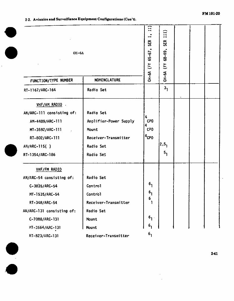
FM 101*20
2-2. Avionics and Surveillance Equipment Configurations (Con't).
0H-6A
i/>
v£> I
LO VO
<✓>
vo i
GO VO
FUNCTION/TYPE NUMBER
VO I
vo I
NOMENCLATURE
RT-1167/ARC-164 Radio Set
VHF/AM RADIO .
AN/ARC-111 consisting of:
AM-4489/ARC-111
MT-3592/ARC-111
RT-802/ARC-ni
AN/ARC-115( )
RT-1354/ARC-186
Radio Set
Amplifier-Power Supply
Mount
Receiver-Transmitter
Radio Set
Radio Set
CPO
CPO
XPO
2,5.
VHF/FM RADIO
AN/ARC-54 consisting of:
C-3835/ARC-54
MT-1535/ARC-54
RT-348/ARC-54
AN/ARC-131 consisting of:
C-7088/ARC-131
MT-3664/ARC-131 «
RT-823/ARC-131
Radio Set
Control
Control
Receiver-Transmitter
Radio Set
Mount
Mount
Recei ver-T ransmi tter
2-41

FM 101-20
2-2. Avionics and Surveillance Equipment Configurations (Con’t).
0H-6A
FUNCTION/TYPE NUMBER
AN/ARC-114( )
AN/ARC-114( )
CU-1759/ARC
CU-1794/ARC
CU-1796/ARC
CU-1893/ARC
AS-1703/AR
CU-1894/ARC
NOMENCLATURE
Radio Set (#1 FM)
Radio Set (#2 FM)
FM Antenna Coupler
#1 FM Homing Transformer
#1 FM Homing Network
#1 FM Antenna Coupler
#2 FM Comm Antenna
#2 FM Antenna Coupler
r-~ to
■ LD VO
<=£ VO
I
CT> VO
I CO VO
VO I
-CPO
2
1
1
1
1
SECURE VOICE
C-8157/ARC
369A6471
TSEC/KY-28
Control-Indi cator
Mount (KY-28)
Corran Security Set
1
1
CPO
GYRO COMPASS
AN/ASN-43 consisting of:
CN-405/ASN
CN-998( )/ASN
Gyro Compass Set
Compensator
Directional Gyro
2-42

FM 101-20
2-2. Avionics and Surveillance Equipment Configurations (Con’t).
0H-6A r*. vo
I m vo
vo i
00 VO
<t vO
I
< VO
FUNCTION/TYPE NUMBER
T-611/ASN
ADF
AN/ARN-83 consisting of:
AS-1863/ARN-83
C-6899/ARN-83
MT-3605/ARN-83
R-1391/ARN-83
AN/ARN-89( ) consisting of:
AM-4859( )/ARN-89
AS-2108( )/ARN-89
C-7392( )/ARN-89
R-1496( )/ARN-89
NOMENCLATURE
Compass Transmitter
Direction Finder Set
Loop Antenna
Control
Mount
Receiver
Direction Finder Set
Amplifier
Loop Antenna
Control
Receiver
IDENTIFICATION
AN/APX-72 consisting of:
C-6280A(P)/APX
MT-3809/APX-72
RT-859( )/AP)t-72
Transponder Set
Control
Mount
Transponder
2-43

FM 101-20
2-2. Avionics and Surveillance Equipment Configurations (Con’t).
0H-6A
FUNCTION/TYPE NUMBER NOMENCLATURE
C'. VO
I in 10
c VO
I
in
vo CO VO
VO
MT-3513/APX
TS-1843( )/APX
AT-884( )/APX
369A6472
MT-3949A/U
KIT-1A/TSEC
Mount (TS-1843)
Test Set
Antenna
Mount (KIT-1A)
Mount (KIT-1A)
IFF Computer 'CPO
1
1
1
1
CPO
POWER SOURCES
BB-641/A
BB-678/A
PP-6674/A
369A4554
Battery
Battery
Static Inverter
Static Inverter
MISCELLANEOUS
ID-1351/A HRB Indicator
2-44

FM 101-20 2-2. Avionics and Surveillance Equipment Configurations (Con’t).
NOTES:
1. 2.
3.
4.
5.
6.
7.
The AN/ARC-51 was temporarily installed in lieu of the AN/ARC-116 in some aircraft. Wiring provisions exist for 2 each AN/ARC-114, 1 each AN/ARC-115 and 1 each AN/ARC-116. However the maximum number of sets that can be installed at any given time is limited to 3 each, i.e., 1 each AN/ARC-114, 115 or 116 or 2 each AN/ARC-114 and 1 each AN/ARC-115 or 2 each AN/ARC-114 and 1 each AN/ARC-116. The AN/ARC-116 and RT-1167 are interchangeable; therefore, either may be installed but not both. Provisions for the AN/ARC-51 and AN/ARC-lH are superimposed; therefore, either system may be installed but not both. The AN/ARC-115 and RT-1354 are interchangeable; therefore, either may be installed but not both. The AN/ARC-54 and AN/ARC-131 are interchangeable; therefore, either may be installed but not both. Retrofit installation.
APPLICABLE AIRCRAFT MANUALS:
TM TM TM TM TM TM TM TM
11-1520-214-20 (Pertains to 0H-6A FY 65-67) 11-1520-214-20-1 (Pertains to 0H-6A FY 68-69) 11-1520-214-20P (Pertains to 0H-6A FY 65-69) 11-1520-214-20P-1 (Pertains to 0H-6A FY 68-69) 11-1520-214-34 (Pertains to 0H-6A FY 65-67) 11-1520-214-34-1 (Pertains to 0H-6A FY68-69) 11-1520-214-34P (Pertains to 0H-6A FY 65-67) 11-1520-214-34P-1 (Pertains to 0H-6A FY 68-69)
2-46

FM 101-20
2-2. Avionics and Surveillance Equipment Configurations (Con’t).
The following configuration depicts a typically configured 0H-58( ). The actual configuration may vary depending on peculiar geographic requirements or changes incorporated through MWO action and special purpose alterations.
FUNCTION/TYPE NUMBER NOMENCLATURE
< co in i
o CO LO
I
o CO in
i
INTERCOMM
C-6533/ARC
C-10414/ARC
206-075-483-1
Intercomm Control
Intercomm Control
Impedance Matching Network
UHF/AM RADIO
AN/ARC-51BX consisting of:
C-6287/ARC-51BX
HD-615/ARC-51X
ID-1003/ARC
MT-2653/ARC
RT-742( )/ARC
AN/ARC-116( ).
Radio Set
Control
Cooler
SWR Indicator
'lount
Recei ver-T ransmi tter
Radio Set
2-46

FM 101*20
2-2. Avionics and Surveillance Equipment Configurations (Con’t).
OH-58( )
FUNCTION/TYPE NUMBER
CO m
i
o CO in
i
NOMENCLATURE
o CO in
i
RT-1167/ARC-164(V)
RT-1145C/ARC-164(V)
C-9533/ARC-164 .
MT-4838/ARC-164
AS-2487/ARC
HPF40-01T
VHF/AM RADIO
AN/ARC-115( )
RT-1354/ARC-186(V)
C-10604(V)3/ARC-186(V)
MI-6051/ARC-186(V)
RT-1300/ARC-186(V)
206-075-518-1
BPF40-03P
Radio Set
Recelver-T ransmi tter
Control
Mount (RT-1145)
UHF Antenna
UHF Hi Pass Filter
Radio Set
Radio Set
Control
Mount(RT-l300)
Recei ver-T ransmi tter
VHF Antenna
VHF Band Pass Filter
2-47

FM 101-20
2-2. Avionics and Surveillance Equipment Configurations (Con’t).
OH-58( )
FUNCTION/TYPE NUMBER
VHF/FM RADIO
AN/ARC-114( )
AN/ARC-114( )
C-10604(V)3/ARC-186
CM-492/ARC-186(V)
MT-6051/ARC-186(V)
RT-1300/ARC-186(V)
AS-2485/ARC
AS-2486/ARC
AS-2670/ARC
206-075-518-1
LPF40-02B
NOMENCLATURE
Radio Set (#1 FM)
Radio Set (#2 FM)
Control
FM Homing Unit
Mount(RT-1300)
Recei ver-T ransmi tter
FM Comm Antenna
#1 FM Homing Antenna (LH)
#1 FM Homing Antenna (RH)
#1 FM Comm Antenna
FM Low Pass Filter
«£ oo LO
I
1
CPO
o oo UT)
I
1
CPO
o 00 LT>
I
2
1
2
2
2
2-48
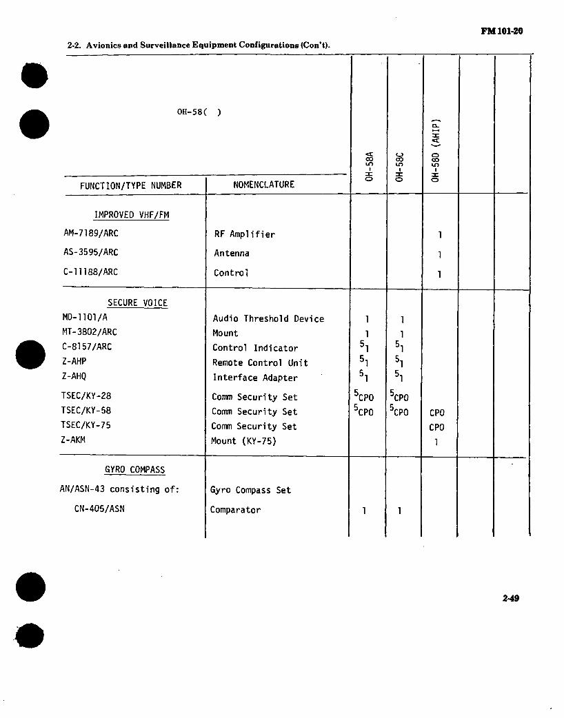
FM 101-20
2-2. Avionics and Surveillance Equipment Configurations (Con’t).
OH-58( )
FUNCTION/TYPE NUMBER
<c oo ir>
■
o co LO
i
o co un
i
NOMENCLATURE
IMPROVED VHF/FM
AM-7189/ARC
AS-3595/ARC
C-11188/ARC
SECURE VOICE
MD-1101/A
MT-3802/ARC
C-8157/ARC
Z-AHP
Z-AHQ
TSEC/KY-28
TSEC/KY-58
TSEC/KY-75
Z-AKM
RF Amplifier
Antenna
Control
Audio Threshold Device
Mount
Control Indicator
Remote Control Unit
Interface Adapter
Comm Security Set
Comm Security Set
Comm Security Set
Mount (KY-75)
3CPO
5CP0
3CPO
5CPO CPO
CPO
1
GYRO COMPASS
AN/ASN-43 consisting of:
CN-405/ASN
Gyro Compass Set
Comparator
2-49

FM 101*20
2-2. Avionics and Surveillance Equipment Configurations (Con't).
OH-58( )
<£ 00 IT)
I
O 00 LO
I
FUNCTION/TYPE NUMBER NOMENCLATURE
n:
o CO cn i
CN-998( )/ASN
T-611/ASN
Directional Gyro
Compass Transmitter
A HRS
406-947-310 Attitude Heading Reference System
ADF
AN/ARN-89( ) consisting of:
AM-4859( )/ARN-89
AS-2108( )/ARN-89
C-7392( )/ARN-89
R-1496( )/ARN-89
206-032-310-3
Direction Finder Set
Amplifier
Loop Antenna
Control
Receiver
ADF Sense Antenna Assy
1
1
1
1
1
V0R/MB/GS
AN/ARN-123(V)1 consisting of:
C-10048/ARN-123(V)
MT-4834/ARN-123(V)
Receiving Set
Control
4ount
CPO
CPO
2-5®

FM 101-20
2-2. Avionics and Surveillance Equipment Configurations (Con’t).
OH-58( )
FUNCTION/TYPE NUMBER NOMENCLATURE
«t co LT)
I
«_> CO LT)
3: o
R-2023/ARN-123(V)
ID-1347C/ARN
AS-1304/ARN
AS-3188/ARN
AT-640( )/ARN
Receiver
Course Indicator
VOR Antenna
GS Antenna
MB Antenna
Doppler Navigation Set
Signal Data Converter
Recei ver-T ransmi tter- Antenna
DOPPLER NAVIGATION
AN/ASN-137 consisting of:
CV-3669/ASN-137
RT-1193/ASN-128
CPO
6CP0
6CP0
6CP0
6CP0
RADAR ALTIMETER
AN/APN-209( )(V)1 consisting of: Radar Altimeter Set
AS-2595/APN-194(V)
RT-1115( )/APN-209(V)
AN/APN-209A(V)3 consisting of:
Antenna
Recei ver-Transmi tter- Height Indicator
ladar Altimeter Set
7CP0
CPO
AS-3586/APN-209A(V)
RT-1411/APN-209A(V)
Intenna
Recei ver-Transmi tter
2
1
2-51
0H
-58D
(AH
IP)

tal 101-20
2-2. Avionics and Surveillance Equipment Configurations (Con’t).
OH-58( )
c oo Lit
I
FUNCTION/TYPE NUMBER NOMENCLATURE
c_> 00
o
IDENTIFICATION
AN/APX-72 consisting of:
C-6280A(P)/APX
MT-3809/APX-72
RT-859( )/APX-72
MT-3513/APX
TS-1843( )/APX
RT-1285( )/APX-100
C-10009/APX-100
MT-481l/APX-100
RT-1157/APX-100
AT-884{ )/APX
206-077-109-1
AT-741( )/A
MT-3949A/U
KIT-1A/TSEC
Transponder Set
Control
Mount
Transponder
Mount (TS-1843)
Test Set
Transponder
Control
Mount (RT-1157)
Transponder
Antenna
Antenna
Antenna
Mount (KIT-1A)
IFF Computer
1
CPO
1
1
1
CPO
1
1
1
2
1
CPO
2-52
0H-5
8D
(AH
IP)

FM 101-20
2-2. Avionics and Surveillance Equipment Configurations (Con’t).
OH-58( )
FUNCTION/TYPE NUMBER
RADAR WARNING
AN/APR-39(V)1 consisting of:
AS-2890/APR-39(V)
AS-2891/APR-39(V)
AS-2892/APR-39(V)
C-9326/APR-39(V)
CM-440/APR-39(V)
IP-1150/APR-39(V)
R-l838/APR-39(V)
AIMS
CP-1516/ASQ
CONTROL/DISPLAY
406-947-307
PROXIMITY WARNING
YG-105401 consisting of:
10027834-101
HG1001-AD01
NOMENCLATURE
Radar Signal Detecting Set
Blade Antenna
Right Spiral Antenna (2 ea)
Left Spiral Antenna (2 ea)
Control
Comparator
Indicator
Receiver (2 ea)
Peripheral Interface Unit
Control/Display System
3roximity Warning System
\ntenna
Receiver-Transmitter
=E CO LD
I
*CP0
°CP0
8CP0
8CP0
BCP0
3CP0
3CPO
82
o 00 IT)
I
CPO
CPO
CPO
CPO
CPO
CPO
CPO
32
a co ir>
i
CPO
CPO
CPO
CPO
CPO
CPO
CPO
2-53
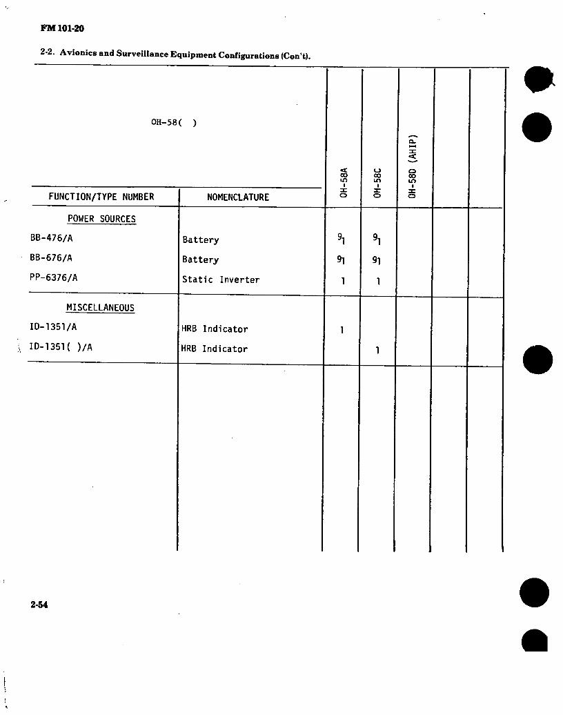
FM 101-20
2-2. Avionics and Surveillance Equipment Configurations (Con’t).
OH-58( )
FUNCTION/TYPE NUMBER
POWER SOURCES
BB-476/A
BB-676/A
PP-6376/A
MISCELLANEOUS
ID-1351/A
ID-1351( )/A
NOMENCLATURE
Battery
Battery
Static Inverter
HRB Indicator
HRB Indicator
oo m
i
91
1
o CO m
i
’i
91
1
o CO in
i
2-64
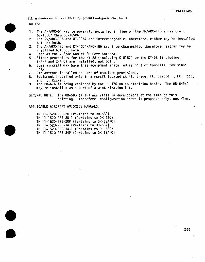
2-2. Avionics and Surveillance Equipment Configurations (Con’t).
NOTES:
FM101-20
1 .
2.
3.
4. 5.
6.
7. 8.
9.
The AN/ARC-51 was temporarily installed in lieu of the AN/ARC-116 in aircraft 68-16687 thru 68-16986. The Afl/ARC-116 and RT-1167 are interchangeable; therefore, either may be installed but not both. The AN/ARC-115 and RT-1354/ARC-186 are interchangeable; therefore, either may be installed but not both. Used as the VHF/AM and #1 FM Comm Antenna. Either provisions for the KY-28 (including C-8157) or the KY-58 (including Z-AHP and Z-AHQ) are installed, not both. Some aircraft may have this equipment installed as part of Complete Provisions Only. Aft antenna installed as part of complete provisions. Equipment installed only in aircraft located at Ft. Bragg, Ft. Campbell, Ft. Hood, and Ft. Rucker. The BB-676 is being replaced by the BB-476 on an attrition basis. The BB-649/A may be installed as a part of a winterization kit.
GENERAL NOTE: The 0H-58D (AHIP) was still in development at the time of this printing. Therefore, configuration shown is proposed only, not firm.
APPLICABLE AIRCRAFT AVIONICS MANUALS:
TM TM TM TM TM TM
11-1520-228-20 (Pertains to 0H-58A) 11-1520-223-20-1 (Pertains to 0H-58C) 11-1520-228-20P (Pertains to 0H-58A/C) 11-1520-228-34 (Pertains to 0H-58A) 11-1520-228-34-1 (Pertains to 0H-58C) 11-1520-228-34P (Pertains to 0H-58A/C)
2-55

FM 101-20
2-2. Avionics and Surveillance Equipment Configurations (Con’t).
The following configuration depicits a typcially configured T-42A. The actual configuration may vary depending on peculiar geographic requirements or changes incorporated through MWO action and special purpose alterations.
FUNCTION/TYPE NUMBER
INTERCOMM
C-161K )/AIC
UHF/AM RADIO
AN/ARC-51BX consisting of:
C-6287/ARC-51BX
HD-615/ARC-51X
ID-1003/ARC
MT-2653/ARC
RT-742( )/ARC
AT-1108/ARC
VHF/AM RADIO
AN/ARC-111 consisting of:
AM-4489/ARC-111
NOMENCLATURE
Intercomm Control
Radio Set
Control
Cooler
SWR Indicator
Mount
Receiver-Transmitter
VHF/UHF Antenna
Radio Set
Amplifier-Power Supply
<c CSJ
I
2-56

FM 101-20
2-2. Avionics and Surveillance Equipment Configurations (Con’tj.
T-42A
FUNCTION/TYPE NUMBER NOMENCLATURE
csj
I
MT-3592/ARC-111
RT-802/ARC-111
T-366/ARC
MT-1142/ARC
DY-86/ARN-30
F-726/AR '
VHF-20( )
G-4582
AT-1108/ARC
Mount (AM-4489)
Receiver-Transmitter
Transmitter
Mount (T-366)
Dynamotor
Fi 1 ter
Radio Set
Control
VHF/UHF Antenna
GYRO COMPASS
C-14 consisting of:
2587193-4
656520
1783867-1
AN/ASN-43 consisting of:
CN-405/ASN
CN-998( )/ASN
Compass System
Gyro-Sync Assembly
Flux Valve
Servo Amplifier
Gyro Compass Set
Compensator
Directional Gyro
2-57

FM 101-20
2-2. Avionics and Surveillance Equipment Configurations (Con’t).
T-42A
FUNCTION/TYPE NUMBER
T-611/ASN
AM-3209/ASN
ADF
AN/ARN-59 consisting of:
AT-780/ARN
C-2275/ARN
DY-150/ARN
MT-2018/ARN
MT-2019/ARN
R-836/ARN
VOR/MB/GS
AN/ARN-30D consisting of:
C-3436/ARN-30E
CV-265A/ARN-30A
ID-453/ARN-30
MT-1174/ARN-30A
MT-1175/ARN-30A
NOMENCLATURE
Compass Transmitter
Servoamplifier
Direction Finder Set
Loop Antenna
Control
Dynamotor
Mount (R-836)
Mount (DY-150)
Receiver
Receiving Set (VOR)
Control
Converter
Course Indicator
Mount (R-102)
Mount (CV-265)
c C\J
2-58
i

FM 101-20
2-2. Avionics and Surveillance Equipment Configurations (Con’t).
T-42A
FUNCTION/TYPE NUMBER NOMENCLATURE
«£ CSJ
I
PP-2792/ARN-30D
R-1021/ARN-30D
CV-1275/ARN
MT-2659/ARN
R-844/ARN-58
ID-1347C/ARN-82
AN/ARN-123(V)1 consisting
C-10048/ARN-123(V)
MT-4834/ARN-123(V)
R-2023/ARN-123(V)
A-138
AT-640( )/ARN
Of
Power Supply
Receiver-
Converter
Mount (CV-1275)
Receiving Set (MB/GS)
Course Indicator
Receiving Set(VOR/MB/GS)
Control
Mount
Receiver
VOR Antenna
MB Antenna
PME
AN/ARN-124 consisting of:
ID-2192/ARN-l24
-MT-6034/ARN-124
RT-1294/ARN-124
PME Set
Control Indicator
Mount
Receiver-Transmitter
2-69

FM 101-20
2-2. Avionics and Surveillance Equipment Configurations (Con’t).
T-42A
FUNCTION/TYPE NUMBER
IDENTIFICATION
AN/APX-72 consisting of:
C-6280A(P)/APX
MT-3809/APX-72
RT-859( )/APX-72
AT-884( )/APX
NOMENCLATURE
Transponder Set
Control
Mount
Transponder
Antenna
c CM
I
POWER SOURCES
BB-432( )/A
PU-542( )/A
MISCELLANEOUS
ID-250( )/ARN
ID-998/ASN
Battery
Inverter
Radio Magnetic Indicator
Radio Magnetic Indicator
NOTES:
1. The AT-1108 is used with 2. The VHF-20( ) is a retro 3. The AN/ASN-43 and AM-320fe 4. The AN/ARN-123 and ID-13T
R-844. 5. Retrofit in|tallation.
both UHF/AM and VHF/AM syst<m it replacement for the AN/AIC are retrofit replacements
7 are retrofit replacements
s. -Ill
the for thi
: or c|nd T-366
C-14 s> AN/ARh
systefn stem. -30, CV
s.
1275, ind
2-60

2-2. Avionics and Surveillance Equipment Configurations (Con’t). FM101-20
# GENERAL NOTE: Commercial equivalents of the military nomenclatured equipment may be installed in some aircraft.
APPLICABLE AIRCRAFT AVIONICS MANUALS: DA publications are not available. Refer to applicable commercial literature.
2-61

FM 101-20
2-2. Avionics and Surveillance Equipment Configurations (Con’t).
The following configuration depicts a typically configured 0V-1( )/RV-lD. The actual configuration may vary depending on peculiar geographic require- ments or changes incorporated through MWO action and special purpose alterations.
FUNCTION/TYPE NUMBER
INTERCOMM
C-161K )/AIC
C-6533/ARC
UHF/AM RADIO
AN/ARC-51BX consisting of:
C-6287/ARC-51BX
HD-615/ARC-51X
ID-1003/ARC
MT-2653/ARC
RT-742( )/ARC
RT-1167/ARC-164(V)
AT-1108/ARC
NOMENCLATURE
Intercomm Control
Intercomm Control
Radio Set
Control
Cooler
SWR Indicator
Mount
Recei ver-T ransmi tter
Radio Set
VHF/UHF Antenna
I o
o I >
o
o I >
o
h
]1
2,
o I
oc
2-62

FM 101-20
2-2. Avionics and Surveillance Equipment Configurations (Con’t).
ov-K )/RV-1D
FUNCTION/TYPE NUMBER NOMENCLATURE
o I
o
VHF/AM RADIO
AN/ARC-134( ) consisting of
C-7197/ARC-l34
MT-3791 ( )/ARC-134
RT-857/ARC-134
AN/ARC-115( )
AT-1108/ARC
Radio Set
Control
Mount
Receiver-Transmi tter
Radio Set
VHF/UHF Antenna
VHF/FM RADIO
AN/ARC-54 consisting of:
C-3835/ARC-54
MT-1535/ARC-54 ,
RT-348/ARC-54
Radio Set
Control
Mount
Recei ver-T ransmi tter
AN/ARC-131 consisting of:
C-7088/ARC-131
MT-3664/ARC-131
RT-823/ARC-131
Radio Set
Control
Mount
Recei ver-T ransmi tter
31
31
3,
3
3
3
1
1
1
2-63
0V
-1D
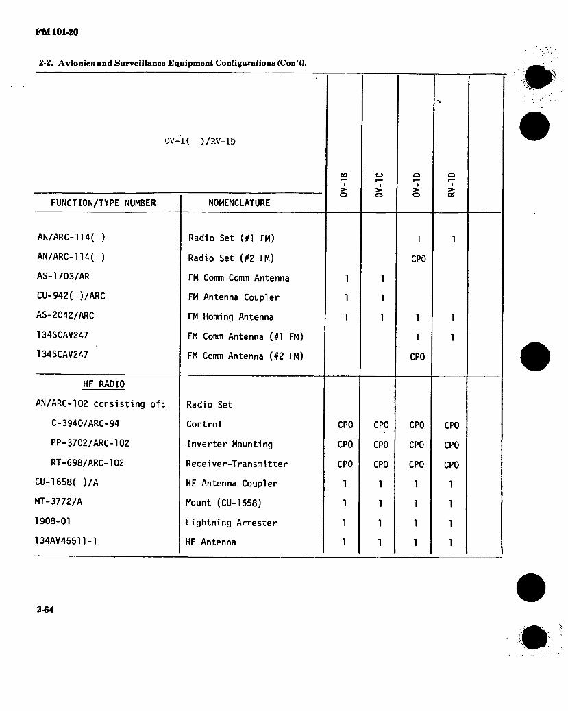
FM 101-20
2-2. Avionics and Surveillance Equipment Configurations (Con’t).
0V-1( )/RV-1D
FUNCTION/TYPE NUMBER
AN/ARC-114( )
AN/ARC-114( )
AS-1703/AR
CU-942( )/ARC
AS-2042/ARC
134SCAV247
134SCAV247
HF RADIO
AN/ARC-102 consisting of:
C-3940/ARC-94
PP-3702/ARC-102
RT-698/ARC-102
CU-1658( )/A
MT-3772/A
1908-01
134AV45511-1
NOMENCLATURE
Radio Set (#1 FM)
Radio Set (#2 FM)
FM Comm Comm Antenna
FM Antenna Coupler
FM Homing Antenna
FM Comm Antenna (#1 FM)
FM Comm Antenna (#2 FM)
Radio Set
Control
Inverter Mounting
Recei ver-T ransmi tter
HF Antenna Coupler
Mount (CU-1658)
Lightning Arrester
HF Antenna
5» o
CP0
CP0
CP0
1
1
1
1
I S» o
CP0
CP0
CP0
1
1
1
1
o I
5» o
1
CP0
1
1
CP0
CP0
CP0
CP0
1
1
1
1
CP0
CP0
CP0
1
1
1
1
m
2-64

FM 101-20
2-2. Avionics and Surveillance Equipment Configurations (Con’t).
OV-K ) /RV-1D
FUNCTION/TYPE NUMBER
SECURE VOICE
MD-736/A
MT-3802/ARC
C-8157/ARC
Z-AHP
Z-AHQ
TSEC/KY-28
TSEC/KY-58
ATTITUDE HEADING
AN/ASN-76 consisting of:
AM-4862/ASN-76
C-8099/ASN-76
CN-1151/ASN-76
MT-3870/A
DT-173/AJN consisting of:
NOMENCLATURE
Signal Discriminator (2 ea
Mount
Control-1ndi cator
Remote Control Unit
Interface Adapter
Comm Security Set
Comm Security Set
Attitude Heading Reference Set
Electronic Control Ampli- fier
Controller
Displacement Gyro
Mount
Magnetic Azimuth Detector
CÛ
> o
I > o
o I
>
CPO
1
CPO
1
fCP0
;CP0
+CP0
^CPO
2-65

FM 101-20
2-2. Avionics and Surveillance Equipment Configurations (Con’t).
ov-K ) /RV-ID
FUNCTION/TYPE NUMBER
CN-1072/AJN
DT-309/AJN
DT-376/ASN
INTEGRATED FLIGHT DIRECTOR
AN/ASN-33 consisting of:-
AM-2853/ASN
CP-583/ASN
ID-882/ASN
ID-883/ASN
MT-2416/ASN
CU-865/ASN
MT-2417/ASN
ADF
AN/ARN-59 consisting of:
AT-780/ARN
C-2275/ARN
NOMENCLATURE
Compensator
Detector (Flux Valve)
Detector (Flux Valve)
Navigation Computer Set
Amplifier
Computer
Attitude-Nav Indicator (Horizontal)
Course Indicator
Mount (AM-2853, CP-853)
Indicator Coupler
Mount (CU-865)
Direction Finder Set
Loop Antenna
Control
I > O
o I
o
o I
> œ
2-66

FM 101-20
2-2. Avionics and Surveillance Equipment Configurations.(Con’t).
OV-K ) /RV-1D
FUNCTION/TYPE NUMBER NOMENCLATURE
CO
I 3* o
I
o
o ■
5» OC
DY-150/ARN
MT-2018/ARN
MT-2019/ARN
R-836/ARN
134AV25518-1
AN/ARN-83 consisting of:
AS-1863/ARN-83
C-6899/ARN-83
MT-3605/ARN-83
R-1391/ARN-83
AN/ARN-89( ) consisting of:
AM-4859( )/ARN-89
AS-2108( )/ARN-89
C-7392( )/ARN-89
R-1496( )/ARN-89
Dynamotor
Mount (R-836)
Mount (DY-150)
Receiver
Sense Antenna ^
Direction Finder Set
Loop Antenna
Control
Mount
Receiver
Direction Finder Set
Amplifier
Loop Antenna
Control
Receiver
VOR
AN/ARN-30E consisting of: Receiving Set (VOR)
2-67

FM 101-20
2-2. Avionics and Surveillance Equipment Configurations (Con’tl.
OV-K ) /RV-1D
FUNCTION/TYPE NUMBER
C-3436A/ARN-30E
CV-265A/ARN-30A
MT-1174/ARN-30A
MT-1175/ARN-30A
PP-2792/ARN-30D
R-l021/ARN-30D
134CS30103-1
AN/ARN-82( ) consisting of^
C-6873B/ARN-82
MT-3600/ARN-82
R-l388( )/ARN-82
MB/GS
R-844( )/ARN-58
AT-134A/ARN
134AV25508-1
134AV35003-1
NOMENCLATURE
Control
Converter
Mount (R-l021)
Mount (CV-265)
Power Supply
Receiver
VOR Antenna
Receiving Set (VOR)
Control
Mount
Receiver
Radio Receiver (MB/GS)
MB Antenna
MB Antenna
GS Antenna
I > o
9l
91
1
I > o
61
61
61
61
61
6,
9l
9,
o I
o
1
9l
9,
I Cd
'1
9l
9,
2-68

FM 101-20
2-2. Avionics and Surveillance Equipment Configurations (Con’t).
OV-K ) /RV-1D
FUNCTION/TYPE NUMBER
AT-326/ARN
R-1963/ARN
MT-4835/ARN
TACAN
AN/ARN-103(V)1 consisting of:
C-8968/ARN-103(V)
CV-2924(P)/ARN-103(V)
MT-4411/ARN-103(V)
RT-1057/ARN-103(V)
AT-741( )/A
SA-521/A
MT-1995/A
DOPPLER NAVIGATION
AN/ASN-64 consisting of:
AN/APN-168( ) consisting of:
NOMENCLATURE
<_> I
> o
GS Antenna
Radio Receiver (MB/GS)
Mount (R-1963)
Doppler Navigation Set
Radar Navigation Set
I > O
o I
az
Navigation Set (TACAN)
Control 1111
Signal Data Converter 1.1 1 1
Mounting 1111
Receiver-Transmitter 1111
Antenna 2222
Antenna Transfer Switch 1111
Mount (SA-521) 1111
2-69
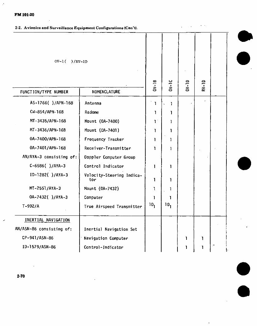
FM 101-20
2-2. Avionics and Surveillance Equipment Configurations (Con’t).
OV-K )/RV—ID
FUNCTION/TYPE NUMBER NOMENCLATURE
CO
I > o
CJ I
5» o
AS-1766( )/APN-168
CW-854/APN-168
MT-3435/APN-168
MT-3436/APN-168
0A-7400/APN-168
0A-7401/APN-168
AN/AYA-3 consisting of:
C-6586( )/AYA-3
ID-1282( )/AYA-3
MT-2551/AYA-3
0A-7432( )/AYA-3
T-992/A
Antenna
Radome
Mount (0A-7400)
Mount (0A-7401)
Frequency Tracker
Receiver-Transmitter
Doppler Computer Group
Control Indicator
Velocity-Steering Indica- tor
Mount (OA-7432)
Computer
True Airspeed Transmitter
1
1
1
1
1
1
1
1
1
1
1
1
1
1
1
1
1
1
1
1
a I
5» O
INERTIAL NAVIGATION
AN/ASN-86 consisting of:
CP-941/ASN-86
ID-1579/ASN-86
Inertial Navigation Set
Navigation Computer
Control-Indicator
i
1 1
1 1
2-70
RV
-1D

FM 101-20
2-2. Avionics and Surveillance Equipment Configurations (Con’t).
OV-K ) /RV-1D
FUNCTION/TYPE NUMBER
MT-4447/ASN-86
MT-4075/ASN-86
MX-8123/ASN-86
T-992/A
RADAR ALTIMETER
AN/APN-22 consisting of:
AM-291/APN-22
CY-1409A/APN-22
ID-257/APN-22
MT-803/APN-22
RT-160/APN-22
AN/APN-171A(V)1 consisting of:'
AS-1858/APN-171(V)
F-1263/APN-171A(V)
ID-1345A/APN-171(V)
NOMENCLATURE
CD
I O
o 1
o
Mount (MX-8123)
Mount (CP-941)
Gyro Stabilized Platform
True Airspeed Transmitter-
Radar Altimeter Set
Electronic Control Amplifier
Receiver-Transmitter Hous- ing
Height Indicator
Mount
Receiver-Transmitter
Radar Altimeter Set
Antenna
Band Suppression Filer
Height Indicator
11.
11:
11.
11.
Hi
n.
iii
n.
10,
o i
> QC
10,
2-71

FM 101-20
2-2. Avionics and Surveillance Equipment Configurations (Con’t).
OV-K ) /RV-1D
FUNCTION/TYPE NUMBER
MT-4167/APN-171 (V)
RT-804A/APN-171(V)
IDENTIFICATION
AN/APX-72 consisting of:
C-6280A(P)/APX
MT-3809/APX-72
RT-859( )/APX-72
TS-1843( )/APX
MT-3513/APX
KIT-1A/TSEC
MT-3949A/U
AT-741( )/A
AUTO PILOT
AN/ASW-12(V)2 consisting of:
C-3106( )/ASW-12(V)
NOMENCLATURE
Mount
Receiver-Transmitter
Transponder Set
Control
Mount
Transponder
Test Set
Mount (TS-1843)
IFF Computer
Mount (KIT-1A)
Antenna
Automatic Flight Control System
Auto Pilot Attitude Control
I > O
1
1
1
1
1
CPO
1
2
o r—
I > o
11.
11.
1
1
1
1
1
CPO
1
2
o i
S» o
1
1
1
1
1
CPO
1
2
o I
Oí
1
1
1
1
1
CPO
1
2
2-72

FM 101-20
2-2. Avionics and Surveillance Equipment Configurations (Con’t).
0V-1( )/RV-1D
FUNCTION/TYPE NUMBER
C-3107( )/ASW-12(V)
C-3108( )/ASW-12(V)
CN-601( )/ASW-12(V)
CU-792/ASW-12(V)
MX-2916( )/ASW-12(V)
MX-2917/ASW-12(V)
MX-2918/ASW-12(V)
MX-2919/ASW-l2(V)
TG-78( )/ASW-12(V)
TG-80( )/ASW-12(V)
TG-81( )/ASW-12(V)
NOMENCLATURE
Auto Pilot Flight Controller
Attitude Reference Control
Displacement Gyro
Navigational Coupler
Accelerometer
Calibration Unit
Calibration Unit
Calibration Unit
Actuator
Actuator
Actuator
1
1
1
1
1
1
1
2
1
1
C_>
I > o
1
1
1
1
1
1
1
2
1
1
o I
> o
1
1
1
1
1
1
1
2
1
1
1
1
1
1
1
1
1
2
1
1
PHOTOGRAPHIC
KS-61A consisting of:
KA-30A consisting of:
LA-131A
LA-134A
Photographic Surveillance System
Still Picture Camera
Lens Cone
Camera Body Drive
12 CPO
12 CPO
12.13 CPO
12.13 CPO
273

FM 101-20
2-2. Avionics and Surveillance Equipment Configurations (Con’tl.
OV-K ) /RV-1D
FUNCTION/TYPE NUMBER NOMENCLATURE i
> o
i 5» o
o I S»
o
LA-135
LA-138A
LA-139A
LA-136A consisting of:
LA-130A
LA-137A
LS-38A consisting of:
LA-96A
LA-152A
LA-153A
LA-154A
LA-155A
LA-156A
LA-157A
LA-158A
LA-159A
Film Cassette Magazine(2ea)
Lens Cone Case
Camera Equipment Case
Lens Cone Group
Lens Cone
Lens Cone Case
( Photographic Control Sys
Attitude Speed Ratio Detector
Power Supply Control
Camera Mount Control
Camera Exposure Control
Flare Reset Control
Master Camera Control
Photoflash Detector
Cartridge Ejector
Cartridge Ejector
12 (
12 C
12
CPO »
CPO >
'CPO
12 C
12 CPO
}
'CPO
12 C
12 (
12 C
12
CPO ?
'CPO- )
"CPO }
'CPO
12 CPO
12 C
12 C
12 C
12
CPO ?
'CPO
CPO
‘CPO
12.13 CPO
12.13 CPO
12.13 CPO
12.13 CPO
12.13 CPO
12 CPO
12.13 CPO
12.13 CPO
12.13 CPO
12.13 CPO
12.13 CPO
12.13 CPO
12.13 CPO
12.13 CPO
2-74
RV
-1D

FM 101-20
2-2. Avionics and Surveillance Equipment Configurations (Con’t).
0V-1( )/RV-1D
FUNCTI0N/TYPÈ NUMBER NOMENCLATURE
CO
I > o
LArieOA
LA-161A
LA-162A
LA-163A
LA-176A
LA-177A
LA-178A
KS-104A consisting of:
KA-76A consisting of:
LA-373A
LA-374A
LA-375A
LA-407A
LA-414A
LS-59A consisting of:
LA-359A
Camera Mount
Light Monitoring Sensor
Oblique Sight (Left)
Oblique Sight (Right)
Attitude-Speed Ratio Converter
Attitude Speed Ratio Coupler
Flight Line Tracker
Photographic Surveillance Sys
Still Pi cutre Camera
Camera Body Drive
Camera Lens Cone
Photographic Shutter
Light Sensor (3 ea)
Film Cassette Magazine (2 ea)
5hotographic Flasher Sys
Carrying Cradle
12 (
12 CPO
12 (
12
CPO >
CPO ?
'CPO
12 CPO
12 (
12 CPO
I CPO
12.13 CPO
12.13 CPO
12.13 CPO
12.13 CPO
12.13 CPO
12.13 CPO
12.13 CPO
12.13 CPO
12.13 CPO
12.13 CPO
112.13 CPO
12.13 CPO
2,13 CPO
2-75
Ql-A
O

FM 101-20
2-2. Avionics and Surveillance Equipment Configurations (Con’t).
0V-1( )/RV-1D
FUNCTION/TYPE NUMBER NOMENCLATURE
CD
I 5» o
<_> I
o
o I
o
TTTTT CPO
12.13 CPO
12.13 CPO
12.13 CPO
12.13 CPO
12.13 CPO
12.13 CPO
12.13 CPO
12.13 CPO
12.13
12^9 CPO
12.13 CPO
12.13 CPO
12.13 CPO
12.13 CPO
12.13 CPO
LA-388A
LA-389A
LA-390A
LA-391A
LA-392A
LA-394A
LS-91A consisting of:
LA-96A
' LA-162A
LA-163A
LA-176A
LA-178A
LA-405A
LA-406A
LA-407A
LA-408A
LA-409A
Pod Assembly
Carrying Case
Cable Assembly
Cover Assembly
Turbine Cover Assembly
Control Box Assembly
Photographic Control Sys
Attitude-Speed Ratio Detector
Oblique Sight (Left)
Oblique Sight (Right)
Altitude-Speed Ratio Converter
Flight Line Tracker
Camera Control
Power Supply Control
Light Sensor
Camera Mount
Actuator Assembly
2-76
RV-1
D

FM 101-20
2-2. Avionics and Surveillance Equipment Configurations (Con’t).
ov-K )
)/RV-lD
CQ u a
, FUNCTION/TYPE NUMBER NOMENCLATURE ■ i
o o ■
2»
o
KS-104B consisting of: Photographic Surveillance System
KA-76A consisting of:
LA-373A
LA-374A
LA-375A
LA-407A
Still Picture Camera
Camera Body Drive
Camera Lens Cone
Photographic Shutter
Light Sensor (3 ea)
12.13 CPO
12.13 CPO
12.13 CPO
12.13 CPO
LA-414A Film Cassette Magazine (2 ea)
12,13 CPO
LS-59A consisting of:
LA-359A
LA-388A
LA-389A
LA-390A
LA-391A
LA-392A
LA-394A
Photographic Flasher Sys
Carrying Cradle
Pod Assembly
Carrying Case
Cable Assembly
Cover Assembly
Turbine Cover Assembly
Control Box Assembly
12.13 CPO
12.13 CPO
12.13 CPO
12.13 CPO
12.13 CPO
12.13 CPO
12.13 CPO
LS-91B consisting of: Photographic Control Sys
LA-96A Altitude-Speed Ratio Detector
12,13 CPO
# 2-77
RV
-lD

FM 101-20
2-2. Avionics and Surveillance Equipment Configurations (Con’t). -
ov-K )/RV-1D
(
FUNCTION/TYPE NUMBER NOMENCLATURE
CÛ
I
o
(-> I >
o
o i
o
LA-162A
LA-163A
Oblique Sight (Left)
Oblique Sight (Right)
12.13 CPO
12.13 CPO
LA-176A
LA-178A
LA-405B
LA-406A
LA-407A
LA-408B
LA-409A
Altitude-Speed Ratio Converter
Flight Line Tracker
Camera Master Control
Power Supply Control
Light Sensor
Camera Mount
Actuator Assembly
12.13 CPO
12.13 CPO
12.13 CPO
12.13 CPO
12.13 CPO
12.13 CPO
12.13 CPO
KA-60C consisting of:
LA-410A
LA-411A
LA-412A
LA-413A
Still Picture Camera
Film Magazine
Camera Body Drive
Camera Control
Camera Control Panel
12.14 CPO
12.14 CPO
12.14 CPO
12.14 CPO
15 CPO
15 CPO
15 CPO
15 CPO
1193064 Mount (LA-412A) 2
KS-113A consisting of: Photographic Surveillance System
2-78
RV
-1D

2-2. Avionics and Surveillance Equipment Configurations (Con’t). FM101-20
ov-K ) /RV-ID
FUNCTION/TYPE NUMBER
KA-76A consisting of:
LA-373A
LA-374A
LA-375A
LA-414A
LA-370A
LA-371A
LA-372A
.LA-434A
LS-59A consisting of:
LA-388A
LA-390A
LA-394A
LS-92A consisting of:
C-8340/A
LA-162A
NOMENCLATURE
CO
f
o I
o
o (
o
o I >
oc
Still Picture Camera
Camera Body Drive
Lens Cone
Photographic Shutter
Film Cassette Magazine (2 ea)
Lens Cone
Lens Cone
Lens Cone
Code Matrix Block Recorder
Flasher System
Pod Assembly
Cable Assembly
Control Box Assembly
Photographic Control Sys
Altitude-Speed Ratio Con- trol
Oblique Sight (Left)
CPO
CPO
CPO
CPO
CPO
CPO
CPO
CPO
CPO
CPO
CPO
1
1
2-79

FM 101-20
2-2. Avionics and Surveillance Equipment Configurations (Con’t).
OV-1( )/RV-1D
FUNCTION/TYPE NUMBER
LA-163A
LA-178A
LA-406A
LA-407A
LA-408B
LA-409A
LA-432A
INFRARED SURVEILLANCE
AN/AAS-14A consisting of:
0A-7825/AAS-14A consist- ing of:
C-6822/AAS-14A
CX-n271/AAS-14A
CX-11272/AAS-14A
CY-4815/AAS-14A
ID-807/U
IP-808/U
SB-2649/AAS-14A
NOMENCLATURE
Oblique Sight (Right)
Flight Line Tracker
Power Supply Control
Light Sensor
Camera Mount
Actuator
Camera Master Control
Infrared Detecting Set
Control Indicator Group
Control
Cable Assembly
Cable Assembly
Equipment Cabinet
Calibration Indicator
Terrain Display Indicator
Switch Control Panel
CO
I S» o
C_J
I S» o
1
1
1
1
1
2
1
o I
> o
1
1
1
3
1
1
1
2-80

FM 101-20 2-2. Avionics and Surveillance Equipment Configurations (Con’t).
ov-K )/RV-1D
co i
o I
FUNCTION/TYPE NUMBER NOMENCLATURE
0A-7827/AAS-14A consist- ing of: Receiver Group
CN-770/AAS-14
R-l386/AAS-14A
AN/USA-23 consisting of:
CY-4811/U
MA-18/U
MT-7186/USA-23
PP-4478/AAS-14A
MT-3582/AAS-14A
AM-4464/AAS-14A
CV-2052/AAS-14A
HD-723/AAS-14A
MK-898/AAS-14A
MT-3610/AAS-14A
MT-4105/AAS-14A
Displacement Gyro
Receiver
Recorder Group
Magazine Case
Film Magazine
Recorder Subassembly
Power Supply
Mount (PP-4478)
Preamplifier
Signal Data Converter
Cyrogenic Refrigerator
Optical Filter Kit
Mount (HD-723)
Mount (CV-2052)
1
1
2
2
1
1
,1
2
1
1
1
1
1
2-81
RV-1
D

FM 101-20
2-2. Avionics and Surveillance Equipment Configurations (Con’t).
OV-K ) /RV-1D
FUNCTION/TYPE NUMBER
AN/AAS-24 consisting of:
NOMENCLATURE
CO
I
o
I
o
a i
o
Infrared Detecting Set 16
CV-2666/AAS-24
CY-6665/AAS-24
HD-841/AAS-24
MX-8357/AAS-24
MX-8358/AAS-24
MX-8359/AAS-24
Video Converter
Film Magazine Case (2 ea)
Rotary Compressor
Detecting Set Subassembly
Converter Subassembly
Recorder Group Blanket
16 (
16
16
CPO
CPO
CPO
CPO
CPO
CPO
OA-8511/AAS-24 consist- ing of:
MA-26/AAS-24
MX-8356/AAS-24
Recorder Group
Film Magazine (2 ea)
Recorder Subassembly
CPO
16CP0
0K-138/AAS-24 consist- ing of:
0K-149/AAS-24 consist- ing of:
C-8182/AAS-24
C-8183/AAS-24
C-8180/AAS-24
IP-970yAAS-24
Control Indicator Group
Terrain Display/Control Group
Receiver Control
Velocity One Height Control
Indicator Control
Terrain Indicator
16 CPO
16 CPO
16 CPO
16CP0
2-82
RV
-1D

FM 101-20
2-2. Avionics and Surveillance Equipment Configurations (Con’t).
ov-K )/RV-1D
FUNCTION/TYPE NUMBER NOMENCLATURE
CO
I 5» o
I > o
a ■
5» o
0K-150/AAS-24 consist- ing of: Calibration Display/Con-
trol Group
IP-969/AAS-24 Calibration Display Indicator
C-8181/AAS-24'
CY-6606/AAS-24 \
MT-4156/AAS-24
PP-6270/AAS-24
R-1615/AAS-24
MT-4157/AAS-24
MT-4158/AAS-24
MT-4159/AAS-24
134F80332-1
Built In Test Control
Equipment Cabinet
Mount
Power Supply
Infrared Receiver
Mount (MX-8357, PP-6270)
Mount (MX-8358)
Mount (CV-2666)
Mount (R-1615)
RADAR SURVEILLANCE
AN/APS-94C consisting of:
AS-1048/APS-94
C-2996/APS-94
Radar Surveillance Set
Antenna Assembly 1
Radar Set Control 1
6 CPO
6 CPO
6 CPO
6 CPO
6 CPO
6 CPO
6 CPO
6 CPO
6 CPO
1
2-83

FM 101-20
2-2. Avionics and Surveillance Equipment Configurations (Con’t).
OV-1( )/RV-1D
FUNCTION/TYPE NUMBER
C-2997/APS-94
CM-145( )/APS-94
IP-516( )/APS-94
IP-517( )/APS-94
J-1098C/APS-94
PP-2404( )/APS-94
RD-166( )/UP
RT-530/APS-94
NOMENCLATURE
Recorder Control
Signal Comparator
Radar Target Indicator
Video Signal Monitor
Interconnection Box
Power Supply
Radar Mapping Recorder
Recei ver-T ransmi tter
QO
I > o
o I
o
1
1
1
1
1
1
1
1
o I
S» o
SN-257A/APS-94 Synchronizer 1
AN/APS-94D consisting of:
AS-2199/APS-94D
C-7645/APS-94D
CM-374/APS-94D
IP-923/APS-94D
J-2794/APS-94D
MT-4015/APS-94
R0-352/APS-94D
Radar Surveillance Set
Antenna
Radar Set Control
Radar Signal Processor
Radar Target Indicator
Interconnecting Box
Equipment Rack
Recorder-Processor-Vi ewer
16.17 CPO
16.17 CPO
16.17 CPO
16.17 CPO
6.17 CPO
6.17 CPO
6.17 CPO
2-84
RV-
1D

FM 101-20
2-2. Avionics and Surveillance Equipment Configurations (Con’t).
0V-1( )/RV-1D
FUNCTION/TYPE NUMBER NOMENCLATURE
CO
I 5» o
<_3
I S» o
Q I
5» ce
RT-899/APS-94D
SG-794/APS-94D
AN/APS-94F consisting of:
AS-3322/APS-94F
C-7645/APS-94D
CM-481/APS-94F
HD-1067/APS-94F
J-2794A/APS-94D
MT-4015/APS-94D
PP-7508/APS-94F
R0-495/U
RT-1283/APS-94F
SG-1127/APS-94E
Receiver-Transmitter
Sweep Generator
Radar Surveillance Set
Antenna
Radar Set Control
Signal Processor
Pressurization Set
Interconnecting Box
Equipment Rack
Power Supply Mount
Recorder-Processor-Vi ewer
Recei ver-Transmi tter
Sweep Generator
16.17 CPO
16.17 CPO
16.17 CPO
16.17 CPO
16.17 CPO
16.17 CPO
16.17 CPO
16.17 CPO
16.17 CPO
16.17 CPO
16.17 CPO
16.17 CPO
DATA LINK
AN/ART-41A
MT-2530/A
AN/AKT-18 consisting of:
Transmitter
Mount
Radar Data Transmitting Set
2-85

FM 101-20
2-2. Avionics and Surveillance Equipment Configurations (Con’t).
OV-K ) /RV-1D
FUNCTION/TYPE NUMBER NOMENCLATURE
i > o i
o
o I
> o
Q I >
cc
C-6598/AR
CV-2094/A
KY-565/AKT-18
MT-2653/ARC
MT-3448/AKT-18
MT-3617/A
SB-2471/AKT-18
T-991/AR
AN/AKT-18A consisting of:
C-6598/AR
C-9963/AKT-18A
KY-565A/AKT-18
MT-2653/ARC
MT-3448/AKT-18
MT-4792/AKT-18A
MT-4793/AKT-18A
Control
Signal Data Converter
Video Encoder
Mount (T-991)
Mount (KY-565)
Mount (CV-2094)
Power Distribution Panel
Transmitter
Radar Data Transmitting Set
Control
Control
Video Encoder
Mount (T-001)
Mount (LY-565A)
Mount (PD-7255)
Mount (J-2794)
1
1
1
1
1
1
1
18 C
18
18
CPO Î CPO
i CPO
18
18 C
18
18
CPO i CPO
i CPO
CPO
2-86
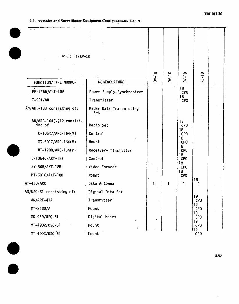
FM 101-20
2-2. Avionics and Surveillance Equipment Configurations (Con’t).
. ov-K )/RV-1D
FUNCTION/TYPE NUMBER NOMENCLATURE
CO
I 5» o
I
o
a ■
o
a ■
ac
. PP-7255/AKT-18A
T-991/AR
AN/AKT-18B consisting of:
Power Supply-Synchronizer
Transmitter
Radar Data Transmitting Set
18 CPO
18 CPO
AN/ARC-164(V)12 consist- ing of:
C-10547/ARC-164(V)
MT-6017/ARC-164(V)
RT-1288/ARC-164(V)
C-10546/AKT-18B
KY-865/AKT-18B
MT-6016/AKT-18B
AT-450/ARC
Radio Set
Control
Mount
Recei ver-T ransmi tter
Control
Video Encoder
Mount
Data Antenna
18 CPO
18 CPO
18 CPO
18 CPO
18 CPO
18 CPO
18 CPO
1 19
1
AN/USQ-61 consisting of:
AN/ART-41A
MT-2530/A
MD-939/USQ-61
MT-4902/USQ-61
MT-4903/USQ-fel
Digital Data Set
Transmitter
Mount
Digital Modem
Mount
Mount
19 CPO
19 CPO
19 CPO
19 CPO
19 CPO
2-87

FM 101-20
2-2. Avionics and Surveillance Equipment Configurations (Con’t).
OV-K ) /RV-1D
FUNCTION/TYPE NUMBER NOMENCLATURE > o
■ s» o
a i
5» O
a ■
5» a:
MT-4904/USQ-61
PP-7036/USQ-61
R-2057/USQ-61
SA-2056/USQ-61
TSEC/KG-35-4
AN/USQ-61A consisting of:
AN/ARC-164(V)12 consist- ing of:
C-10547/ARC-164(V)
MT-6017/ARC-164(V)
RT-1288/ARC-164(V)
MT-4903/USQ-61
MT-4904/USQ-61
PP-7652/USQ-61A
MD-1102/USQ-61
TSEC/KG-( )
AT-256/ARC
Mount (TSEC/KG)
Power Supply
Radio Receiver
Transmit-Receive Switch
Key Generator
Digital Data. Set
Radio Set
Control
Mount
Recei ver-T ransmi tter
Mount (PP-7652)
Mount (TSEC/KG)
Power Supply
Digital Modem
Key Generator
Data Antenna
19 i
19
19 C
19
CPO i
CPO ) CPO
3 CPO
19 CPO
19 C
19 CPO
3 CPO
19 CPO
19 C
19 C
19 £
19
CPO 3 CPO
3 CPO
19 C
19
CPO 3 CPO
2-88

FM 101-20
2-2. Avionics and Surveillance Equipment Configurations (Con’t).
ov-K )/RV-1D
FUNCTION/TYPE NUMBER NOMENCLATURE
QO
I > o
o I
o I
> o
DATA ANNOTATION
AN/AYA-10 consisting of:
C-8338/AYA-10
CV-2647/AYA-10
MT-4539/AYA-10
IP-1080/AYA
TR-253/AYA
Data Annotation System
Control-Moni tor
Signal Data Converter
Mount
Digital Indicator (2 ea)
Altitude Transducer
1
1
1
CPO
1
AERIAL RADIAC
AN/ADR-6(V) consisting of:
C-81 63/ADR-6
CP-854/ADR-6
DT-322/ADR-6
ID-1581/ADR-6
R0-301/ADR-6
Aerial Radiac Set
Control/Alarm Panel
Computer/Power Supply
Detector
Indicator
Recorder
20 CPO
20 CPO
20 CPO
20 CPO
20 CPO
RADAR WARNING
AN/ALR-46(V) consisting of:
AM-6639/ALR»-46 ( V )
Radar Signal Detecting Set
Amplifier-Detector (4 ea) 21
CPO 21
CPO
2-89
RV-1
D
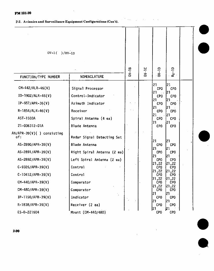
FM 101-20
2-2. Avionics and Surveillance Equipment Configurations (Con’t).
OV-K ) /RV-1D
FUNCTION/TYPE NUMBER
CM-442/ALR-46(V)
ID-1902/ALR-46(V)
IP-957/APR-36(V)
R-1854/ALR-46(V)
AST-1503A
21-036312-01A
AN/APR-39(V)( ) consisting of:
AS-2890/APR-39(V)
AS-2891/APR-39(V)
AS-2892/APR-39(V)
C-9326/APR-39(V)
C-10412/APR-39(V)
CM-440/APR-39(V)
CM-480/APR-39(V)
IP-1150/APR-39(V)
R-1838/APR-39(V)
ES-D-221604
NOMENCLATURE
Signal Processor
Control-Indicator
Azimuth Indicator
Receiver
Spiral Antenna (4 ea)
Blade Antenna
Radar Signal Detecting Set
Blade Antenna
Right Spiral Antenna (2 ea)
Left Spiral Antenna (2 ea)
Control
Control
Comparator
Comparator
Indicator
Receiver (2 ea)
Mount (CM-440/480)
CO
I
(_) I
5» o
I S» o
21 (
21 (
21 (
21 (
21 (
21
CPO I ■ , CPO
I CPO
I CPO
I CPO
I CPO
21 CPO
21 CPO
21 CPO
21,22 CPO
21,22 CPO
21,22 CPO
21,22 CPO
21 CPO
21 CPO
21 CPO
o I > or
21 (
21 I
21 (
21 (
21 I
21
CPO I CPO
I CPO
I CPO
I CPO
I CPO
21 CPO
21 CPO
21 CPO
21,22 CPO
21,22 CPO
21,22 CPO
21,22 CPO
21 CPO
21 CPO
121 CPO
2-90

FM 101-20
2-2. Avionics and Surveillance Equipment Configurations (Con’t).
ov-K ) /RV-ID
FUNCTION/TYPE NUMBER NOMENCLATURE
QO
I > o
o ■
o
o ■
o
Q I
O?
AN/APR-44(V)3 consisting of:
AS-3266/APR-44(V)
C-10387/APR-44(V)
F-1503/APR-44(.V)
R-2097/APR-44(V)
R-2098/APR-44(V)
Radar Signal Detecting Set
Antenna (4 ea)
Control
Low Pass Filter
Receiver
Receiver
23 C
23 CPO
5 CPO
23 CPO
23 (
23 CPO
i CPO
23 CPO
23 CPO
23 CPO
23 CPO
23 CPO
PROP SYNCHROPHASER * AN/AJA-5 consisting of:
SN-324/AJA-5
MT-2695/AJA-5
550512
Propeller Synchrophaser Set
Synchrophaser-
Mount
Speed Bias Assembly
1
1
2
COUNTERMEASURES
AN/ALQ-147A(V)1 consisting of:
C-10698/ALQ-147A(V)
MD-1074/ALQ-147A(V)
T-1407/ALQ-»147A(V)
Countermeasures Set
Control Unit
Modulator Assembly
Transmitter Assembly
CPO
CPO
CPO
2-91

FM 101-20
2-2. Avionics and Surveillance Equipment Configurations (Con’t).
OV-1( )/RV-1D
FUNCTION/TYPE NUMBER
AN/ALQ-147A(V)2 consisting of:
C-10698/ALQ-147A(V)
MD-1074/ALQ-147A(V)
T-1408/ALQ-147A(V)
AN/ALQ-133 consisting of:
0K-270/ALQ-133 con- sisting of:
AW/UYK-23
BB-507/U
C-9537/ALQ-133
C-9538/ALQ-133
CU-2104/ALQ-133
&-1672/ALQ-133
PP-7035/ALQ-133
MS91405-C2D
MS91405-B1C
NOMENCLATURE
Countermeasures Set
Control Unit
Modulator Assembly
Transmitter Assembly
Countermeasures Receiving Set
Quantizer-Control Group
Computer (2 ea)
Battery (2 ea)
Moni tor-Control 1 er
Control-Indicator
Power Divider (2 ea)
Frequency Synthesizer (2 ea)
Power Supply
Mount (C-9537)
Mount (0-1672)
CÛ
I > o
o I >
o I
o
o I >
a:
CPO
CPO
CPO
CPO
CPO
CPO
CPO
CPO
CPO
CPO
1
2
2-92

FM 101-20
2-2. Avionics and Surveillance Equipment Configurations (Con’t).
0V-1( )/RV-1D
FUNCTION/TYPE NUMBER
MS91405-C2D
MS91405-B1D2
0R-140/ALQ-133 consist- ing of:
AS-2994/ALQ-133
C-9536/ALQ-133
CM-446/ALQ-133
CM-447/ALQ-133
CV-3171/ALQ-133
CV-3174/ALQ-133
CV-3395/ALQ-133
CV-3396/ALQ-133
CY-7410/ALQ-133
CO r-*
I > o
NOMENCLATURE
Mount (PP-7035)
Mount (AN/UYK-23)
Intercept Receiver Group (2 ea)
Spiral Antenna (4 ea)
Power Supply Control
Phase Comparator
Signal Comparator
Converter-Processor
Frequency Converter (2 ea)
Converter-Processor Group
Converter-Processor Group
Intercept Receiver Pod
O
o I >
O'
CPO
CPO
CPO
CPO
CPO
CPO
CPO
CPO
2
POWER SOURCES
0K-279/A consisting of:
BB-708/U
C-9606/A
Voltage Controller Group
Battery
Voltage Controller
2-93

FM 101-20
2-2. Avionics and Surveillance Equipment Configurations (Con't).
OV-K ) /RV-lD
FUNCTION/TYPE NUMBER NOMENCLATURE
CÛ
I
O
o I
> o
Q I >
o
o I >
ID-1979/A
MT-4685/A
BB-433( )/A
PU-544( )/A
PU-545( )/A
PU-750( )/A
Control-Indicator
Mount
Battery
Inverter
Inverter
Inverter
1
2
1
MISCELLANEOUS
ID-250( )/ARN
ID-663( )/U
24 24 Radio Magnetic Indicator 1
Bearing-Distance-Heading 24 24 Indicator 1
2-94

FM 101-20
2-2. Avionics and Surveillance Equipment Configurations (Con’t).
NOTES:
1. 2. 3.
4.
5.
6.
7. 8. 9.
10. 11. 12. .13.
14.
15.
16.
17. 18. 19.
20.
21. 22.
23. 24.
The RT-1167/ARC-164 is a retrofit replacement for the AN/ARC-51 system. The AT-1108 is used with both the VHF/AM and UHF/AM systems. The AN/ARC-54 and AN/ARC-131 are interchangeable; therefore, either may be installed but not both. Either provisions for the KY-28 (including C-8157) or the KY-58 (including Z-AHP and Z-AHQ) are installed but not both. The DT-376/ASN can be substituted for the DT-309/AJN when a special adapter cable is used. The AN/ARN-59 was replaced by the AN/ARN-83 and the AN/ARN-30 was replaced by the AN/ARN-82 beginning with FY 66 aircraft. The R-1963 is a retrofit replacement for the R-844. Either the AT-326 (Collins 37P4) or the 134AV35003-1 is installed, but not both. Either the AT-134A/ARN or the 134AV25508-1 is installed but not both. The T-992 is part of the AN/ASN-64 Doppler Nav System in 0V-1B/C aircraft and used with the AN/ASN-86 Inertial Nav System in 0V-1D/RV-1D Aircraft. The AN/ARN-22 was replaced by the AN/HPN-171 beginning with FY 68 aircraft. Some components of these systems are installed as a part of Complete Provisions Only. The KS-61A system is installed thru FY 66 aircraft; the KS-104A system is installed in FY 67 aircraft and the KS-104B system is installed in FY 68 aircraft. Provisions for 1 each KA-60C system is installed in FY 66 thru FY-68 aircraft in addition to the KS-61/A or KS-104 ( ) systems. Provisions for 2 each KA-60C systems are installed in addition to the KS-113A systems. Provisions for the AN/AAS-24 and AN/APS-94( ) are superimposed; therefore, either system may be installed but not both. The AN/APS-94F (CPO) is a retrofit replacement for the AN/APS-94D (CPO). The AN/AKT-18B (CPO) is a retrofit replacement for the AN/AKT-18A (CPO). The AN/USQ-61A(CP0) and AT-256 are retrofit replacements for the AN/USQ-61 (CPO) and AT-450. Provisions for the AN/ADR-6 are removed when provisions for the AN/APS-94F and AN/AKT-18B are installed. The AN/APR-39(CP0) is a retrofit replacement for the AN/ALR-46 (CPO). The C-9326 and CM-440, part of the AN/APR-39(V)1 system are interchangeable with, the C-10412 and CM-480, part of the AN/APR-39(V)2 system; therefore, either may be installed but not both. Retrofit installation. The ID-250 is installed in lieu of the ID-663 in a few aircraft.
APPLICABLE AIRCRAFT AVIONICS MANUALS:
TM 11-1510-204-20/1 (Pertains to 0V-1B) TM 11-1510-204-20-1/1 (Pertains to 0V-1C) TM 11-1510-204-20-1/2 (Pertains to 0V-1C) TM 11-1510-204-20/2 (Pertains to 0V-1B) TM 11-1510-204-20-2-1 (Pertains to 0V-1D) TM 11-1510-204-20-2-2 (Pertains to 0V-1D)
(CONTINUED)
2-95
I

FM 101-20
2-2. Avionics and Surveillance Equipment Configurations (Con’t).
TM 11-1510-204-20P-1 (Pertains to 0V-1C) TM 11-1510-204-20P-2 (Pertains to 0V-1D) TM 11-1510-204-34-2-1 (Pertains to 0V-1D) TM 11-1510-204-34-2-2 (Pertains to 0V-1D) TM 11-1510-204-34P-1 (Pertains to 0V-1C) TM 11-1510-204-34P-2 (Pertains to 0V-1D) TM 11-1510-204-35-1 (Pertains to 0V-1C) TM 11-1510-204-35/1 (Pertains to 0V-1B) TM 11-1510-204-35/2 (Pertains to 0V-1B) TM 11-1510-213-20-1 (Pertains to RV-1D) TM 11-1510-213-20-2 (Pertains to RV-1D) TM 11-1510-213-20P (Pertains to RV-1D) TM 11-1510-213-34 (Pertains to RV-1D) TM 11-1510-213-34P (Pertains to RV-1D)
ft
2-96

FM 101-20
2-2. Avionics and Surveillance Equipment Configurations (Con’t).
TH-55( )
FUNCTION/TYPE NUMBER NOMENCLATURE
<c ir> m
■
INTERCOMM
MX-1646/AIC Headset Adapter
VHF/AM RADIO
524A
A-25A
Radio Set
Antenna
POWER SOURCES
12-GCAB-9E Battery
APPLICABLE AIRCRAFT AVIONICS MANUALS: DA Publications are not available. Refer to applicable commercial literature.
2-97

FM 101-20
2-2. Avionics and Surveillance Equipment Configurations (Con’t).
The following configuration depicts a typically configured U-8F. The actual configuration may vary depending on peculiar geographic, requirements or changes incorporated through MWO action and special purpose alterations. a
ÜJ M
a 3
FUNCTION/TYPE NUMBER NOMENCLATURE co
i CO
I
INTERCOMM
C-l611( )/AIC
SB-329/AR
MX-1646/AIC
Intercomm Control
Signal Distribution Panel 2
Headset Adapter 2
UHF/AM RADIO
AN/ARC-55( ) consisting of:
C-8127/ARC-55
MT-1536/ARC-55
RT-349( )/ARC-55
AT-1108/ARC
AN/ARC-51BX consisting of:
C-6287/ARC-51BX
Radio Set
Control
Mount
Recei ver-T ransmi tter
VHF/UHF Antenna
Radio Set
Control
2-98

FM 101-20
2-2. Avionics and Surveillance Equipment Configurations (Con’t).
U-8F
FUNCTION/TYPE NUMBER NOMENCLATURE
CO
a LLJ 1^1
o o
CO I
HD-615/ARC-51X
ID-1003/ARC
MT-2653/ARC
RT-742( )/ARC
Cooler
SWR Indicator
Mount
Recei ver-T ransmi tter
VHF/AM RADIO
AN/ARC-73A consisting of:
C-4074/ARC-73A
MT-2699/ARC-73
R-l123/ARC-73
T-879/ARC-73
T-366/ARC
C-4209/ARC
MT-1142/ARC
AN/ARC-134( ) consisting of:
C-7197/ARC-l34
MT-3791( )/ARC-134
RT-857/ARC-134
AT-1108/ARC
Radio Set
Control
Mount
Receiver
Transmitter
Transmi tter
Control
Mount (T-366)
Radio Set
Control
Mount
Recei ver-T ransmi tter
VHF/UHF Antenna
2-99

FM 101-20
2-2. Avionics and Surveillance Equipment Configurations (Con’t).
U-8F o LÜ l-sj
FUNCTION/TYPE NUMBER NOMENCLATURE
co i
a o s;
co
VHF/FM RADIO
AN/ARC-44 consisting of:
AT-454/ARC-44
DY-107B/AR
^MT-1267A/AR
MT-1268/AR
RT-294B/ARC-44
SB-327/ARC-44
AN/ARC-54 consisting of:
C-3835/ARC-54
MT-1535/ARC-54
RT-348/ARC-54
AN/ARC-131 consisting of:
C-7088/ARC-131
MT-3664/ARC-131
RT-823/ARC-131
AS-1703/AR
CU-942( )/ARC
Radio Set
Antenna
Dynamotor
Mount (DY-107)
Mount (RT-294)
Recei ver-T ransmi tter
Control Panel
Radio Set
Control
Mount
Recei ver-T ransmi tter
Radio Set
Control
Mount
Recei ver-T ransmi tter
FM Comm Antenna
FM Antenna Coupler
2100

FM 101-20
2-2. Avionics and Surveillance Equipment Configurations (Cqn’t).
U-8F
FUNCTION/TYPE NUMBER
HF RADIO
AN/ARC-102 consisting of:
C-3940/ARC-94
PP-3702/ARC-102
RT-698/ARC-102
CU-991/AR
MT-1719/AR
CU-1658( )/A
MT-3772A/A
NOMENCLATURE
Radio Set
Control
Inverter-Mounting
Recei ver-T ransmi tter
HF Antenna Coupler
Mount (CU-991)
HF Antenna Coupler
Mount (CU-1658)
co i
r-J
o£ UèJ a o
co i
CPO
CPO
CPO
CPO
CPO
CPO
CPO
CPO
CPO
CPO
SECURE VOICE
MD-736/A
C-8157/ARC
MT-3802/ARC
TSEC/KY-28
Signal Discriminator
Control-Indicator
Mount (KY-28)
Comm Security Set
2»
CPO
CPO
CPO
GYRO COMPASS
AN/ASN-13 consisting of:
AM-1514/ÁSN
Gyro Compass Set
Electronic Control Amplifier
2-101

FM 101-20
2-2. Avionics and Surveillance Equipment Configurations (Con’t).
U-8F
co
o UJ rvi
or LU a o
co
FUNCTION/TYPE NUMBER
CN-405/ASN
ID-567/ASN
T-611/ASN
NOMENCLATURE
Compensator
Compass Indicator
Compass Transmitter
ADF
AN/ARN-59 consisting of:
AT-780/ARN
C-2275/ARN
DY-150/ARN
MT-2018/ARN
MT-2019/ARN
R-836/ARN
Direction Finder Set
Loop Antenna
Control
Dynamotor
Mount (R-836)
Mount (DY-150)
Receiver
VOR
AN/ARN-30E consisting of:
AS-580A/ARN
C-3436A/ARN-30E
CV-205A/ARN-30A
ID-453/ARN-30
Receiving Set (VOR)
VOR Antenna
Control
Converter
Course Indicator
1,
2-102

FM 101-20 ‘
2-2. Avionics and Surveillance Equipment Configurations (Cdn’t).
U~8F
FUNCTION/TYPE NUMBER NOMENCLATURE
oo ■
a txl
o o
CO I
MT-1174/ARN-30A
MT-1175/ARN-30A
PP-2792/ARN-30D
R-1021/ARN-30D
CV-1275/ARN
MT-2659/ARN
Mount (R-1021)
Mount (CV-265)
Power Supply
Receiver
Converter
Mount (CV-1275)
MB
AN/ARN-12 consisting of:
MT-589A/ARN-12
R-122A/ARN-12
AN/ARN-32 consisting of:
MT-1546/ARN-32
R-666B/ARN-32
AT-640( )/ARN
Receiving Set (MB)
Mount
Receiver
Receiving Set (MB)
Mount
Receiver
MB Antenna
GS
AN/ARA-54 consisting of:
C-2065/AR
Receiving Set (GS)
Control
2103

FM 101-20
2*2. Avionics and Surveillance Equipment Configurations (Con't).
U-8F
FUNCTION/TYPE NUMBER NOMENCLATURE
CO I
Q UJ r*J
Q
oo ' i
MT-1762/AR
R-746/AR
Mouht
Receiver
TACAN
AN/ARN-52 consisting of:
C-2010/ARN-52(V)
MT-3680/ARN-52(V)
RT-384/ARN-52(V)
AT-741( )/A
Navigation Set
Control
Mounting
Recei ver-T ransmi tter
Antenna
WEATHER RADAR
AN/APN-158( ) consisting of:
AS-1520( )/APN-l58
C-4881/APN-150
IP-724( )/APN-158
MT-3068/APN-158
MT-3069/APN-158
RT-711( )/APN-l58
SN-358( )/APN-158
Weather Radar Set
Antenna
Control
Azimuth Range Indicator
Mount (RT-711)
Mount (SN-358)
Recei ver-T ransmi tter
Synchronizer
2-104

FM 101-20
m 2-2. Avionics and Surveillance Equipment Configurations (Cqn’t).
U-8F £3 LLI r-j
Q o
FUNCTION/TYPE NUMBER
IDENTIFICATION
AN/APX-72 consisting of:
C-6280A(P)/APX
MT-3809/APX-72
RT-859( )/APX-72
MT-3513/APX
TS-1843( )/APX
MT-3949A/U
KIT-1A/TSEC
AT-884( )/APX
oo ■ CO ■ NOMENCLATURE
Transponder Set
Control
Mount
Transponder
Mount (TS-1843)
Test Set
Mount (KIT-1A)
IFF Computer
Antenna
1
1
1
1
1
1
CPO
1
1
1
1
1
1
1
CPO
1
POWER SOURCES
BB-432( )/A
PU-543( )/A
PU-544( )/A
MISCELLANEOUS
AM-3209/ASN
ID-250( )/ARN
10-387/ARN
Battery
Inverter
Inverter
Servoamplifier
Radio Magnetic Indicator
Course Indicator JCP0
2-105

FM 101-20
2-2. Avionics and Surveillance Equipment Configurations (Con’t).
U-8F
FUNCTION/TYPE NUMBER
ID-663( )/U
ID-998/ASN
NOMENCLATURE
Beari ng-Di stance-Headi ng- Indicator
Radio Magnetic Indicator
oo
a UJ
O o
00 I
5CP0
1
2-106

. ./■ -
FM 101-20 /
2-2. Avionics and Surveillance Equipment Configurations (Con’t).
NOTES:
1. 2.
3.
.4.
5. 6.
The AT-1108 is used with both UHF/AM and VHF/AM systems. The AN/ARC-54 and AN/ARC-131 are interchangeable; therefore, either may be installed but not both. Either 2 each ADF and 1 each VOR or 1 each ADF and 2 each VOR systems may be installed. Either 1 each ADF, 1 each NOR and 1 each TACAN or 2 each ADF and 1 each VOR or 1 each ADF and 2 each VOR systems may be installed. Either the AN/ARN-12 or the AN/ARN-32 system is installed, not both. The ID-387 and ID-663 are installed in lieu of the ID-250 with the ADF/VOR/TACAN configuration.
GENERAL NOTE: The modernized configuration pertains to those aircraft which have had avionics standardization (ZYR/ZYU) MWO's applied.
APPLICABLE AIRCRAFT AVIONICS MANUALS:
TM 11-1510-201-20 TM 11-1510-201-20P TM,11-1510-201-20P-2 TM;11-1510-201-34P-2 TM 11-1510-201-35 TM 11-1510-201-35P
2107

FMlOl-20
2-2. Avionics and Surveillance Equipment Configurations (Con’t).
The following configuration depicts a typically configured U-21( )/RU-21( ). The actual configuration may vary depending on peculiar geographic require- ments or changes incorporated through MWO action and special purpose alterations.
FUNCTION/TYPE NUMBER
INTERCOMM
C-1611( )/AIC
NOMENCLATURE
Intercomm Control
UHF-AM RADIO
AN/ARC-51BX consisting of:
C-6287/ARC-51BX
HD-615/ARC-51X
ID-1003/ARC
MT-2653/ARC
RT-742( )/ARC
AT-1108/ARC
RT-1167/ARC-164
Radio Set
Control
Cooler
SWR Indicator
Mount
Recei ver-T ransmi tter
VHF/UHF Antenna
Radio Set
o < csj i
CSJ I CSJ I CSJ I
2-108
» I I
RU
-21H

FM 101-20 !
2-2. Avionics and Surveillance Equipment Configurations (Con’t).
U-21( )/RU-21( )
FUNCTION/TYPE NUMBER
VHP/AM RADIO
AN/ARC-134( ) consisting of
C-7197/ARC-l34
MT-3791( )/ARC-134
RT-857/ARC-134
AT-1108/ARC
VHF/FM RADIO
AN/ARC-54 consisting of:
C-3835/ARC-54
MT-1535/ARC-54
RT-348/ARC-54
AN/ARC-131 consisting of:
C-7088/ARC-131
MT-3664/ARC-131
RT-823/ARC-131
AS-1703/AR
CU-942( )/ARC
NOMENCLATURE
CD
CVJ I
CSJ I
CO
CSJ
Radio Set
Control
,Mount
Recei ver-T ransmi tter
VHF/UHF Antenna
Radio Set
Control
Mount
Recei ver-T ransmi tter
Control
Mount
Recei ver-T ransmi tter
FM Comm Antenna
FM Antenna Coupler
21
21
21
21
21
2i
2l
2l
2l
2l
2l
2,
CVJ I
2l
2l
2l
2l
2l
2,
CSJ I
# 2-109

FM 101-20 /
/ ' /
2-2. Avionics and Surveillance Equipment Configurations (Con’t).
U-21( )/RU-21( )
FUNCTION/TYPE NUMBER
AS-1922/ARC
AS-2285/ARC
HF RADIO
AN/ARC-102 consisting of:
C-3940/ARC-94
RT-698/ARC-102
50-345772
CU-1658( )/A
MT-3772A/A
50-345615-601
50-346063-3
91-340045-1
SECURE VOICE
MD-736/A
C-8157/ARC
MT-3802/ARC
TSEC/KY-28
NOMENCLATURE
FM Homing Antenna
FM Comm Antenna
Radio Set
Control
Recei ver-T ransmi tter
Mount
Antenna Coupler
Mount (CU-1658)
HF Antenna
HF Antenna
HF Antenna
Signal Discriminator
Control-Indicator
Mount (KY-28)
Comm Security Set
o c CNJ
3
1
1
CP0
CM I
2
1
1
CP0
CÛ
CM
2
1
1
CP0
C_J
CM
CP0
CP0
3CP0
CP0
CP0
CP0
2
1
1
CP0
31
CSJ
3
3
3
CPO
2-110

FM 101-20
2-2. Avionics and Surveillance Equipment Configurations (Con’t).
U-21( )/RU-21( )
FUNCTION/TYPE NUMBER
GYRO COMPASS
AN/ASN-43 consisting of:
CN-405/ASN
CN-998( )/ASN
T-611/ASN
AD F
AN/ARN-83 consisting of:
AS-1863/ARN-83
C-6899/ARN-83
MT-3605/ARN-83
R-1391/ARN-83
50-345611
50-345812
VOR ,
AN/ARN-82( ) consisting of:
C-6873B/ARN-82
ID-1347C/ARN-82
NOMENCLATURE
Compensator
Directional Gyro
Compass Transmitter
Direction Finder Set
Loop Antenna
Control
Mount
Receiver
ADF Sense Antenna
ADF Sense Antenna
C.0
cvj CVJ
I
Receiving Set (VOR)
Control
Course Indicator
C\J I
CM I
CM I
2-111
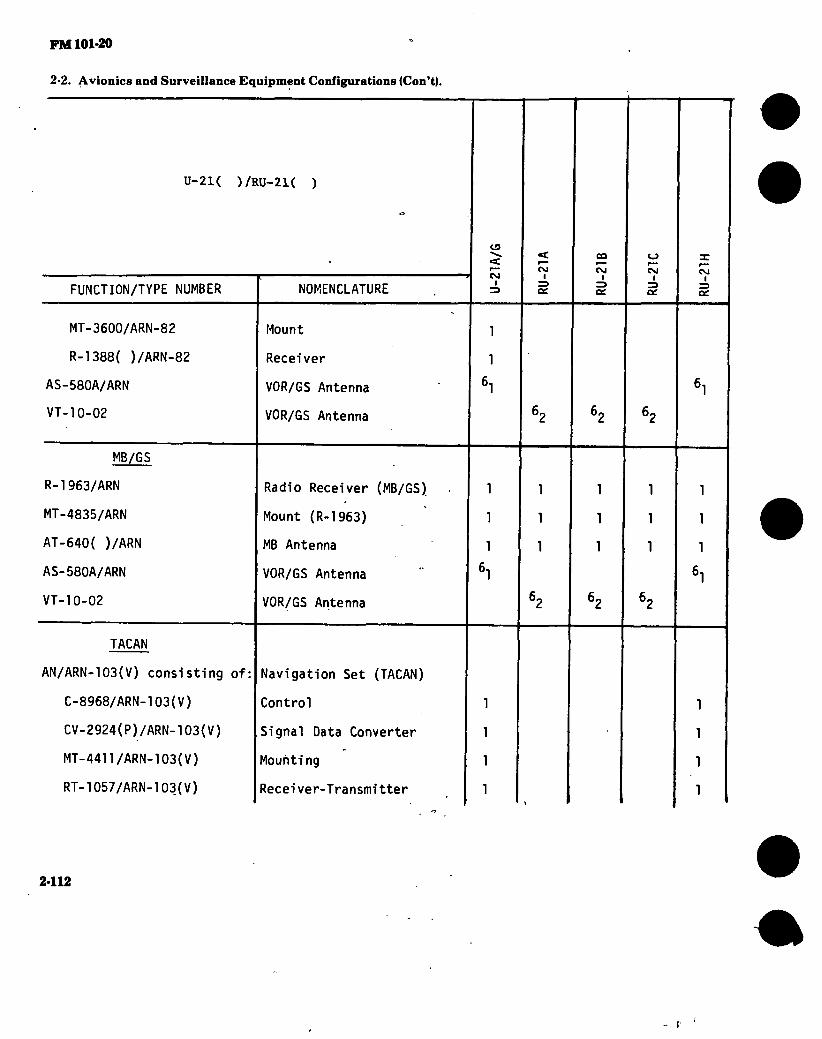
FM 101-20
2-2. Avionics and Surveillance Equipment Configurations (Con’t).
U-21( )/RU-21( )
FUNCTION/TYPE NUMBER
MT-3600/ARN-82
R-l388( )/ARN-82
AS-580A/ARN
VT-10-02
MB/GS
R-l963/ARN
MT-4835/ARN
AT-640( )/ARN
AS-580A/ARN
VT-10-02
TACAN
AN/ARN-103(V) consisting of:
C-8968/ARN-103(V)
CV-2924(P)/ARN-103(V)
MT-4411/ARN-103(V)
RT-1057/ARN-103(V)
NOMENCLATURE
Mount
Receiver
VOR/GS Antenna
VOR/GS Antenna
Radio Receiver (MB/GS)
Mount (R-l963)
MB Antenna
VOR/GS Antenna
VOR/GS Antenna
Navigation Set (TACAN)
Control
Signal Data Converter
Mounting
Recei ver-T ransmi tter
o < CSJ
I
CNJ I
2412
CO
CSJ
o CS4
I CM
I
I

FM 101-20
2-2. Avionics and Surveillance Equipment Configurations (Con’t).
U-21( )/RU-21( )
FUNCTION/TYPE NUM8ÉR
AT-884( )/APX .
339D-1
AN/ARN-102 consisting of:
0046-101-5109
0046-101-5110
8010000152
INERTIAL NAVIGATION
AN/ASN-86 consisting of:
CP-941/ASN-86
ID-1579/ASN-86
MT-4447/ASN-86
MT-4075/ASN-86
MX-8123/ASN-86
T-611/ASN
CN-405/ASN
T-992/A
o «t C\J
c CM
NOMENCLATURE
Antenna
Distance Indicator
Navigation Set (TACAN)
Receiver-Transmitter
Control
Mount
Inertial Navigation Set
Navigation Computer
Control-Indicator
Mount (MX-8123)
Mount (CP-941)
Gyro Stabilized Platform
Compass Transmitter
Compensator
True Airspeed Transmitter
2
1
1
1
1
CM I
2
1
1
1
1
CM I
“C
CM
2
1
1
1
1
2-113

FM 101-20
2-2. Avionics and Surveillance Equipment Configurations (Con’t).
0-21( )/RU-21( )
FUNCTION/TYPE NUMBER
WEATHER RADAR
AN/APN-158( ) consisting of:
AS-1520( )/APN-l58
C-4881/APN-158
IP-724( )/APN-l58
MT-3068/APN-158
MT-3069/APN-158
RT-7n( )/APN-l 58
SN-358( )/APN-l58
AN/APN-215(V)1 consisting of:
AS-3451/APN-215(V)
ID-1376/APN-215(V)
MT-5203/APS-505
RT-1352/APN-215(V)
IDENTIFICATION
AN/APX-72 consisting of:
NOMENCLATURE
Weather Radar Set
Antenna
Control
Azimuth Range & Indicator
Mount (RT-711)
Mount (SN-358)
Recei ver-T ransmi tter
Synchronizer
Weather Radar Set
Antenna
Indicator
Mount
Recei ver-T ransmi tter
13
C\J I
71
71
71
7,
Transponder Set
OJ I
CSJ I
71
71
71
7,
CSJ I
71
71
71
7,
CM I
71
71
71
71
7,
2-114
#

FM 101-20
2-2. Avionics and Surveillance Equipment Configurations (Con’t).
U-21( )/RU-21( )
FUNCTION/TYPE NUMBER
C-6280A(P)/APX
MT-3809/APX-72
RT-859( )/APX-72
TS-1843( )/APX
MT-3513/APX
AT-884( )/APX
MT-3949A/U
KIT-1A/TSEC
NOMENCLATURE
Control
Mount
Transponder
Test Set
Mount (TS-1843)
Antenna
Mount (KIT-1 A)
IFF Computer
C3
c CM
I
<C
CM
CO
CM
1
1
1
1
1
1
1
CPO
1
1
1
1
1
1
1
CPO
1
1
1
1
1
1
1
CPO
CM I
1
1
1
1
1
1
1
CPO
CM I
1
1
1
1
•' 1
1
1
CPO
AUTOPILOT
H-l 4 Automatic Flight Control System
ATTITUDE INDICATING
MD-1
MC-1
Displacement Gyro
Rate Gyro
RADAR WARNING
AN/APR-39(V)1 consisting of: f
Radar Signal Detecting Set •
2-115

FM 101-20
2-2. Avionics and Surveillance Equipment Configurations (Con’t).
U-21( )/RU-21( )
FUNCTION/TYPE NUMBER
AS-2890/APR-39(V)
AS-2891/APR-39(V)
AS-2892/APR-39(V)
C-9326/APR-39(V)
CM-440/APR-39(V)
IP-1150/APR-39(V)
R-1838/APR-39(V)
AN/APR-44(V)3 consisting of:
AS-3266/APR-44(V)
C-10387/APR-44(V)
F-l503/APR-44(V)
R-2097/APR-44(V)
R-2098/APR-44(V)
NOMENCLATURE
POWER SOURCES
BB-433( )/A
E551-11220-6
50-345764-1
Blade Antenna
Right Spiral Antenna (2 ea)
Left Spiral Antenna (2 ea)
Control
Comparator
Indicator
Receiver (2 ea)
Radar Signal Detecting Set | i
Antenna (4 ea)
Control
Low Pass Filter
Receiver
Receiver
CD
< CM
I
CM I
Battery
Battery
Main Inverter *4,9,
°CP0
8CP0
8CP0
8CP0
8CP0
8CP0
3CP0
°CP0
8CP0
BCP0
3CP0
3CP0
CM I
°CP0
8CP0
BCP0
3CP0
3CP0
3CP0
3CP0
3CP0
3CP0
3CP0
3CP0
’CPO
CM I
°CP0
8CP0
3CP0
3CP0
3CP0
3CP0
3CP0
DCP0
3CP0
3CP0
3CP0
3CP0
CM I
°CP0
8CP0
8CP0
3CP0
3CP0
3CP0
3CP0
aCP0
3CP0
3CP0
3CP0
"CPO
2-116

FM 101-20
2-2. Avionics and Surveillance Equipment Configurations (Con’t).
U-21( )/RU-21( )
FUNCTION/TYPE NUMBER NOMENCLATURE
CO
«a: CM
I
«I
CM
CO
CM CM I
CM I
50-345764-2
50-345764-5
50-345764-6
PU-544( )/A
MGH 229-100
Standby Inverter
Main Inverter
Standby Inverter .
INS Inverter
INS Inverter
4.91
5.91
5,9,
MISCELLANEOUS
AM-3209/ASN
ID-250( )/ARN
ID-351B/ARN
ID-387/ARN
ID-998/ASN
50-345974
AN/ARA-50 consisting of:
AM-3 624/ARA-50
AS-909/ARA-48
MT-1955/ARA-50
Servoamplifier
Radio Magnetic Indicator
Course Indicator
Course Indicator
Radio Magnetic Indicator
Radio Magnetic Indicator
UHF Direction Finder Set
Amplifier
Loop Antenna
Mount (AM-3624)
1
10
10
101
10,
1
CP0
CP0
CP0
10i
1°1
]11
CP0
CP0
CP0
1°1
101
1]1
CP0
CP0
CP0
1
2
..]°1 10
2-117

FM 101-20
2-2. Avionics and Surveillance Equipment Configurations (Con’t).
NOTES:
1. The AT-1108 is used with both the VHF/AM and UHF/AM systems. 2. The AN/ARC-54 and AN/ARC-131 are interchangeable; therefore, either may be installed
but not both. 3. Made from PP-3702/ARC-102. 4. Installed in U-21A only. 5. Installed in U-21G only. 6. Used with both the VOR and Glide Scope systems. 7. The AN/AP.N-215 system isa retrofit replacement for the AN/APN-158 system. 8. Retrofit installation. 9. Made from PU-545/A.
10. The ID-351B and ID-387 are interchangeable; therefore, either may be installed but not both.
11. Made from ID-998/ASN.
GENERAL NOTES: 1.
2.
3.
The above configurations do not include mission equipment installed in RU-21 Series aircraft. The U-21F aircraft is not listed in the above configurations because it contains all commercial avionics equipment. Data sheets or supply information for these items will not appear in this publication. Support of these items is the responsibility of the user. Some U-21A/G aircraft have had a non-standard commercial avionics package installed by King Radio Corporation. Data sheets or supply information for these items will not appear in this publication. Support of these items is the responsibility of the user.
APPLICABLE AIRCRAFT AVIONICS MANUALS:
TM 11-1510-209-20 (Pertains to U-21A/G) TM 11-1510-209-20-1 (Pertains to RU-21B/C) TM 11-1510-209-20-4 (Pertains to RU-21A) TM 11-1510-209-20-5 (Pertains to RU-21H) TM 11-1510-209-20P (Pertains to U-21A/G) TM 11-1510-209-20P-1 (Pertains to RU-21B/C) TM 11-1510-209-20P-4 (Pertains to RU-21A) TM 11-1510-209-24P-5 (Pertains to RU-21H) TM 11-1510-209-34P (Pertains to U-21A/G) TM 11-1510-209-34P-1 (Pertains to RU-21B/C) TM 11-1510-209-34P-4 (Pertains to RU-21A) TM 11-1510-209-35 (Pertains to U-21A/G) TM 11-1510-209-35-1 (Pertains to RU-21B/C) TM 11-1510-209-35-4 (Pertains to RU-21A) TM 11-1510-209-35-5 (Pertains to RU-21H)
2-118

FM 101-20
2-2. Avionics and Surveillance Equipment Configurations (Con’t).
The following configuration depicts a typically configured UH-1( )/EH-l( ). The actual configuration may vary depending on peculiar geographic requirements or changes incorporated through MWO action and special purpose alterations.
CM
FUNCTION/TYPE NUMBER NOMENCLATURE
o m
i ■ rc
i ■ 3=
INTERCOMM
C-1611( )/AIC
C-6533/ARC
Intercomm Control
Intercomm Control
UHF/AM RADIO
AN/ARC-51BX consisting of:
C-6287/ARC-51BX
HD-615/ARC-51X
ID-1003/ARC
MT-2653/ARC
RT-742( )/ARC
AT-1108/ARC
RT-1167/ARC-164(V)
Radio Set
Control
Cooler
SWR Indicator
Mount
Recei ver-T ransmi tter
VHF/UHF Antenna
Radio Set
41
41
41
4,
2-119

V
FM 101-20
2-2. Avionics and Surveillance Equipment Configurations (Con’t).
UH-K )/EH-l( )
FUNCTION/TYPE NUMBER
VHF/AM RADIO
AN/ARC-73A consisting of:
C-4074/ARC-73A
MT-2699/ARC-73
R-l123/ARC-73
T-879/ARC-73
T-366/ARC
C-4209/ARC
MT-1142/ARC
DY-86/ARN-30
AN/ARC-134( ) consisting of:
C-7197/ARC-134
MT-3791( )/ARC-134
RT-857/ARC-134
AN/ARC-115( )
RT-1354/ARC-186
AT-1108/ARC
NOMENCLATURE
Radio Set
Control
Mount
Receiver
Transmitter
Transmitter
Control
Mount (T-366)
Dynamotor
Radio Set
Control
Mount
Recei ver-T ransmi tter
Radio Set
Radio Set
VHF/UHF Antenna
O CÛ
4.6
4.6
4.6
4.6
6
5,7-j
5,7,
I 31 ZD
4,6]
4.61
4.61
4,6,
°1
61
P.7, 51
3Z I
2-120
+
EH
-1X
(NO
TE
2)

FM 101-20
2-2. Avionics and Surveillance Equipment Configurations (Con’t).
UH-K )/EH-l( )
FUNCTION/TYPE NUMBER NOMENCLATURE
<_> CO
I 3: i
3:
VHF/FM RADIO
AN/ARC-54 consisting of:
C-3835/ARC-54
MT-1535/ARC-54
RT-348/ARC-54
AN/ARC-131 consisting of:
C-7088/ARC-131
MT-3664/ARC-131 RT-823/ARC-131
AN/ARC-114( )
AS-1703/AR
CU-942( )/ARC
FM 10-30-1
AS-3352/ARC
CU-2239/ARC
AS-1922/ARC
AS-3350/ARC
AS-3351/ARC
Radio Set (#1 FM)
Control
Mount
Recei ver-T ransmi tter
Radio Set (#1 FM)
Control
Mount Recei ver-T ransmi tter
Radio Set (#2 FM)
FM Comm Antenna
FM Antenna Coupler
FM Comm Antenna
FM Comm Antenna
FM Antenna Coupler
FM Homing Antenna
FM Homing Antenna (RH)
FM Homing Antenna (LH)
8l 81
JCP0
1°1
1°1 10,
81 81 81
3CP0
101
10
10, l
2-121
EH
-1X
(NO
TE
2)

FM 101-20
2-2. Avionics and Surveillance Equipment Configurations (Con’t).
UH-K )/EH-l( )
FUNCTION/TYPE NUMBER
HF RADIO
AN/ARC-102 consisting of:
C-3940/ARC-94
PP-3702/ARC-102
RT-698/ARC-102
CU-991/AR
CU-1658( )/A
MT-1719/AR
MT-3772/A
205-706-027-1
SECURE VOICE
MD-736/A
MD-1047/A
MT-3802/ARC
C-8157/ARC
Z-AHP
Z-AHQ
NOMENCLATURE
Radio Set
Control
Inverter-Mounting
Recei ver-T ransmi tter
HF Antenna Coupler
HF Antenna Coupler
Mount (CU-991)
Mount (CU-1658)
HF Antenna
Signal Discriminator
Audio Threshold Device
Mount
Control-Indicator
Remote Control Unit
Interface Adapter
O CÛ
CPO
CPO
CPO
CPO
CPO
CPO
121
12, 12,
CPO
CPO
CPO
CPO
CPO
CPO
CPO
CPO
121
121
12,
I :z>
121
12, 12,
X
I :E UJ
12i
12, 12,
2-122

FM 101-20
2-2. Avionics and Surveillance Equipment Configurations (Con’t).
UH-K )/EH-l( )
FUNCTION/TYPE NUMBER NOMENCLATURE
c_> CO
I X
I
TSEC/KY-28
TSEC/KY-58
Comm Security Set
Comm Security Set
12
12
CPO
CPO
12
12,
CPO
CPO
12
12
CPO
CPO
12
12
CPO
CPO
GYRO COMPASS
J-2 consisting of:
A-2
CN-405/ASN
S-3( )
T-611/ASN
AN/ASN-43 consisting of:
CN-405/ASN
CN-998( )/ASN
T-611/ASN
Gyro Compass Set
Amplifier
Compensator
Gyro Control
Compass Transmitter
Gyro Compass Set
Compensator
Directional Gyro
Compass Transmitter
13
13
13
13
131
131
13,
131
131
131
13,
131
13, 13,
ADF
AN/ARN-59 consisting of:
AT-780/ARN
C-2275/ARN
Direction Finder Set
Loop Antenna
Control
141
14,
141
14,
2-123

FM 101-20
2-2. Avionics and Surveillance Equipment Configurations (Con’t).
UH-K )/EH-l( )
FUNCTION/TYPE NUMBER
DY-150/ARN
MT-2018/ARN
MT-2019/ARN
R-836/ARN
AN/ARN-83 consisting of:
AS-1863/ARN-83
C-6899/ARN-83
MT-3605/ARN-83
R-1391/ARN-83
205-075-325-1
204-075-328-1
V0R/MB/GS
AN/ARN-30E consisting of:
C-3436A/ARN-30E
CV-265A/ARN-30A
ID-453/ARN-30
MT-1174/ARN-30A
NOMENCLATURE
Dynamotor
Mount (R-836)
Mount (DY-150)
Receiver
Direction-Finder Set
Loop Antenna
Control
Mount
Receiver
ADF Sense Antenna
ADF Sense Antenna
Receiving Set (VOR)
Control
Converter
Course Indicator
Mount (R-1021)
O CÛ
141
141
141
141
141
141
141
14,
I I
151
151
15i
15,
141
141
141
14,
141
141
141
14,
151
151
151
15,
I
2-124

2-2. Avionics and Surveillance Equipment Configurations (Con’t).
FM101-20
UH-K )/EH-l( )
FUNCTION/TYPE NUMBER NOMENCLATURE
<_3
CÛ
I
MT-1175/ARN-30A
PP-2792/ARN-30D
R-1021/ARN-30D
CV-1275/ARN
MT-2659/ARN
AN/ARN-82( ) consisting of:
C-6873B/ARN-82
ID-1347C/ARN-82
MT-3600/ARN-82
R-l388( )/ARN-82
AS-1304/ARN
R-1041( )/ARN
MT-2292/ARN
AT-640( )/ARN
R-l963/ARN
MT-4835/ARN
AN/ARN-123(V)3 consisting of:
Mount (CV-265)
Power Supply
Receiver
Converter
Mount (CV-1275)
Receiving Set (VOR)
Control
Course Indicator
Mount /
Receiver
VOR Antenna
Radio Receiver (MB)
Mount (R-1041)
MB Antenna
Radio Receiver (MB/GS)
Mount (R-l963)
Receiving Set (VOR/MB/GS)
151
151
151
151
15,
151
15,
15
15 1
1
CPO
CPO
1
151
151
151
15i
15,
151
15,
15
15
1
1
T
CPO
CPO
1
16l
16,
1
1
1
1
1
CPO
CPO
1
2-125
EH
-1X
(NO
TE
2)

FM 101-20
2-2. Avionics and Surveillance Equipment Configurations (Con’t).
UH-K )/EH-l( )
FUNCTION/TYPE NUMBER
o CO
I NOMENCLATURE
C-l0048/ARN-l23(V)
MT-4980/ARN-123(V)
R-2023/ARN-123(V)
AS-3188/ARN
Control
Mount
Receiver
GS Antenna 16,
PME
AN/ARN-124 consisting of:
ID-2192/ARN-124
MT-6034/ARN-124
RT-1294/ARN-124
AT-741( )/A
PME Set
Control Indicator
Mount
Recei ver-T ransmi tter
Antenna
161
161
16l
16,
TACAN
AN/ARN-103(V)1 consisting of:
C-8968 ARN-103(V)
CV-2924(P)/ARN-103(V)
MT-4411/ARN-103(V)
RT-1057/ARN-103(V)
TACAN Set
Control
Signal Pata Converter
Mount
Recei ver-Transmi tter
2-126
EH
-1X
(NO
TE
2)

FM 101-20 2-2. Avionics and Surveillance Equipment Configurations (Con’t).
UH-K )/EH-l( )
o CO
I
FUNCTION/TYPE NUMBER
AT-741( )/A
SA-521/A
MT-1995/A
INERTIAL NAVIGATION
AN/ASN-86 consisting of:
CP-941/ASN-86
ID-1579/ASN-86
MT-4447/ASN-86
MT-4075/ASN-86
MX-8123/ASN-86
CN-405/ASN
T-611/ASN
RADAR ALTIMETER
AN/APN-209( )(V)( ) consisting of:
AS-2595/APN-194(V)
ID-1917/APNT209(V)
RT-1115( )/APN-209(V)
NOMENCLATURE
I nr
Antenna
Switch Assembly
Mount (SA-521)
Inertial Navigation Set
Navigation Computer
Control-Indicator
Mount (MX-8123)
Mount (CP-941)
Gyro Stabilized Platform
Compensator
Compass Transmitter
Radar Altimeter Set
Antenna
Height Indicator
Recei ver-T ransmi tter- Height Indicator
152
15,
15,
o
m 2-127

FM 101-20
2-2. Avionics and Surveillance Equipment Configurations (Con’t).
UH-K )/EH-l( )
FUNCTION/TYPE NUMBER NOMENCLATURE
o CO
I I 3C rD
I X
I
IDENTIFICATION
AN/APX-72 consisting of:
C-6280A(P)/APX
MT-3809/APX-72
MT-859( )/APX-72
MT-3513/APX
TS-1843( )/APX
AT-884( )/APX
MT-3949A/U
KIT-1A/TSEC
Transponder Set
Control
Mount
Transponder
Mount (TS-1843)
Test Set
Antenna
Mount (KIT-1A)
IFF Computer
ATTITUDE INDICATING
MD-1
MC-1
Displacement Gyro
Rate Gyro
RADAR WARNING
AN/APR-39(V)1 consisting of:
AS-2890/APR-39(V)
AS-2891/APR-39(V)
1
1
1
1
1
1
1
CPO
17,
Radar Signal Detecting Set
Blade Antenna
Right Spiral Antenna (2 ea)
1
1
1
1
1
1
1
CPO
17,
16
16
CPO
CPO
1
1
1
1
1
1
1
CPO
17,
CPO
CPO
1
1
1
1
1
1
1
CPO
CPO
CPO
2-128

FM 101-20
2-2. Avionics and Surveillance Equipment Configurations (Con’t).
UH-K )/EH-l( )
FUNCTION/TYPE NUMBER
AS-2892/APR-39(V)
C-9326/APR-39(V)
CM-440/APR-39(V)
IP-1150/APR-39(V)
R-1838/APR-39(V)
AN/APR-44(V)1 consisting of:
AS-3266/APR-44(V)
C-10387/APR-44(V)
F-1503/APR-44(V)
R-2097/APR-44(V)
PROXIMITY WARNING
YG-1054D1 consisting of:
10027834-101
HG-1001-AD01
NOMENCLATURE
Left Spiral Antenna (2 ea)
Control
Comparator
Indicator
Receiver (2 ea)
Radar Signal Detecting Set
Antenna (2 ea)
Control
Low Pass Filter
Radar Receiver
Proximity Warning System
Antenna
Recei ver-T ransmi tter
O
CO
I I :n
> i
16
16
16,
16
16
CP0
CP0
CP0
CP0
CP0
182
18,
182
18,
CP0
CP0
CP0
CP0
CP0
CP0
CP0
CP0
CP0
X
I
CP0
CP0
CP0
CP0.
CP0
CPO
CPO
CPO
CPO
2-129

FM 101-20
2-2. Avionics and Surveillance Equipment Configurations (Con’t).
UH-K )/EH-l(
o CQ
I
FUNCTION/TYPE NUMBER NOMENCLATURE
i
COUNTERMEASURES
AN/ALQ-144(V)1 consisting of Countermeasures Set
C-10280/ALQ-144
CY-7611/ALQ-144
T-1360(V)1/ALQ-144
AN/ARQ-33A consisting of
AB-1264/ARQ-33
AN/APN-171A(V)1
AN/ARC-131
AN/GLR-9(V)11
AN/TLQ-17A(V)2
AN/UNH-16A
AS-1703/AR
AS-3381/ARQ-33
C-l611D/AIC
C-8157/ARC
C-8882/ARQ-33
Control
Transit Case
Transmitter
Countermeasures Set
Base
Radar Altimeter Set
VHF/FM Radio Set
Receiving Set
Countermeasures Set
Recorder/Reproducer
Antenna
Antenna
Intercomm Set
Control-Indicator
Control-Indicator
CPO
CPO
CPO
1
1
1
1
1
2
1
1
3
1
1
2-130
EH
-1X
(NO
TE
2)

FM 101-20
2-2. Avionics and Surveillance Equipment Configurations (Con’t).
UH-K )/EH-l( )
FUNCTION/TYPE NUMBER NOMENCLATURE
CO
I az
C-8883/ARQ-33
C-8983/ARQ-33
CU-2245/ARQ-33
ID-1825/ARQ-33
J-3038/ARQ-33
J-3054/ARQ-33
J-3686/ARQ-33
MT-3802/ARC
MT-4424/ARQ-33
MT-4425/ARQ-33
MT-4426/ARQ-33
0J-224A/ARQ-33
0J-472/ARQ-33
RE-1078/ARQ-33
RE-1124/ARQ-33
SA-1823/ARQ-33
SA-1862/ARQ-33
FM 10-30-1
Control-Indi cator
Control -Indi cator
Antenna Coupler
Indicator-Panel
Interconnecting Box
Interconnecting Box
Interconnecting Box
Mount
Rack
Rack
Rack
Console
Console
Relay Assembly
Relay Assembly
Switch Assembly
Foot Switch
Antenna
1
1
1
1
1
1
1
1
1
1
1
1
1
1
1
1
2
2131
EH
-1X
(NO
TE
2)

FM 101-20
2-2. Avionics and Surveillance Equipment Configurations (Con’t).
UH-K )/EH-l( )
o — CO
I
FUNCTION/TYPE NUMBER
AN/ALQ-151 consisting of:
AM-7121/ALQ-151
AN/UYH-1
AN/UYK-19
AN/UYQ-10(V)1
AS-3130/ALQ-151
C-161K )/AIC
C-10026/USQ
C-10027/USQ
C-10050/USQ
, C-10144/ALQ-151
C-11002/USQ
F-1429/ALQ-151
F-l515/ALQ-l51
ID-2090/ALQ-151
ID-2091/U
ID-1251/USQ
NOMENCLATURE
Countermeasures Set
Amplifier
Recorder/Reproducer Set
Computer
Plasma Display
Antenna
Intercomm Set
Control-Indi cator
Control-Indicator
Control-Indi cator
Control-Indicator
Control
Bandpass Filter
Low Pass Filter
Panel Indicator
BDH Indicator
Panaramic Indicator
v 1
1
1
1
4
2
1
1
1
1
1
2
1
1
1
1
2-132
EH
-1X
(NO
TE
2)

FM 101-20
2-2. Avionics and Surveillance Equipment Configurations (Con’t).
UH-K )/EH-l( )
o
00
I
FUNCTION/TYPE NUMBER NOMENCLATURE
J-3400/ALQ-151
J-3415/ALQ-l51
KY-836/ALQ-151
MX-9855/ALQ-151
MX-10250/USQ
MX-10251/USQ
0E-330/ALQ-151
PP-6875A/UNH-16A
PP-7292A/USQ
PP-7293A/USQ
PP-7294A/USQ,
PP-7472/TLQ-17A
R-2017/U
R-2107/TLQ-17A
RD-385A/UNH-16A
RE-1131/ALQ-151
RT-1167/ARC-164
Distribution Box
Distribution Box
Keyboard
DF Interface
Processor
Processor
Antenna Group
Power Supply
Power Supply
Power Supply
Power Supply
Power Supply
Receiver
Receiver
Recorder-Reproducer
Relay Assembly
Radio Set
rc
1
1
.1
1
1
1
1
1
,1^ 1
1
;1
2
.1
1
1 . 2
2-133
EH
-1X
(NO
TE
2)

r
FM 101-20
2-2. Avionics and Surveillance Equipment Configurations (Con’t).
UH-K )/EH-l( )
FUNCTION/TYPE NUMBER
T-1386/TLQ-17A
TSEC/KG-45
TSEC/KY-58
TT-580(V)1/U
G-1169
1951-1-1009
204-075-705-45
3686-8000
5065792-1
POWER SOURCES
BB-433( )/A
PU-543( )/A
MISCELLANEOUS
AM-3209/ASN
ID-250( )/ARN
ID-663C/U
NOMENCLATURE
Transmitter
Electronic Gey Generator
Comm Security Set
Teleprinter
Antenna
Power Line Filter
Caution Panel
Bite Antenna
Power Sensor
Battery
Inverter
Servoamplifier
Radio Magnetic Indicator
Beari ng-Di stance-Headi ng Indicator
O CO
I □c I in
1
CP0
CP0
1
2
1
1
1
2
2-134

2-2. Avionics and Surveillance Equipment Configurations (Con’t).
FM101-20
m UH-K )/EH-l( )
<_}
co
FUNCTION/TYPE NUMBER NOMENCLATURE
ID-998/ASN
PP-7618/U
TD-1136/A
SA-2357/A
Radio Magnetic Indicator 1
Power Supply (5V)
Tunable Diplexer
Switch Assembly
16
1 1
1
1
2135
UH
-1V
(NO
TE
1)

FM 101-20
2-2. Avionics and Surveillance Equipment Configurations (Con’t).
NOTES:
1. Only UH-1V peculiar avionics are listed. Other installed/CPO items will depend on the IMS of the aircraft selected for UH-1V designation.
2. The EH-1X was still in development at the time of this printing. Therefore, the configuration shown is proposed only, not firm.
3. The C-1611 was replaced by the C-6533 and the MD-736 was replaced by the MD-1047 beginning with FY 71 aircraft.
4. Provisions for the AN/ARC-51 and AN/ARC-73 are superimposed in UH-1B/C/M aircraft thru 66-15105 and UH-1H aircraft thru 66-16306; therefore, either radio system may be installed but not both.
5. The AT-1108 is used with both UHF/AM and VHF/AM systems. 6. The AN/ARC-73 and T-366 systems were replaced by the AN/ARC-134 beginning with
66-15106 UH-1B/C/M aircraft and in 66-16307 thru FY 70 UH-1H aircraft. The AN/ARC-115 replaced the AN/ARC-134 beginning with FY 71 UH-1H aircraft and is a retrofit replacement for the AN/ARC-73 and T-366 systems in both UH-1B/C/M and UH-1H aircraft so equipped.
7. The AN/ARC-115 and RT-1354/ARC-186 are interchangeable; therefore, either may be installed but not both.
8. The AN/ARC-54 and AN/ARC-131 are interchangeable; therefore, either may be installed but not both.
9. Provisions for the AN/ARC-114 (#2 FM set) are standard in FY 71-76'UH-1H aircraft. Provisions in all other aircraft may be added by a retrofit installation.
10. The AS-1703 and CU-942 are used with the AN/ARC-54/131 system and the FM 10-30-1 is used with the AN/ARC-114 system in all aircraft except FY 71-76 UH-1H aircraft in which the AS-1703 and CU-942 are used with the AN/ARC-114 and the FM 10-30-1 is used with the AN/ARC-54/131.
11. Provisions for the CU-991 and MT-1719 were replaced by provisions for the CU-1658 and MT-3772 beginning with FY 68 aircraft.
12. Either provisions for the KY-28 (including C-8157) or the KY-58 (including Z-AHP and Z-AHQ) are installed, not both.
13. The J-2 system was replaced by the AN/ASN-43 beginning with 66-15148 UH-1B/C/M aircraft and 66-16449 UH-1H aircraft. The CN-405 and T-611 are common to both.
14. The AN/ARN-59 system was replaced by the AN/ARN-83 beginning with 66-602 UH-1B/C/M aircraft and 66-746 UH-1H aircraft.
15. The AN/ARN-30 system (including the CV-1275) was replaced by the AN/ARN-82 begin- ning with 66-602 UH-1B/C/M aircraft and 66-746 UH-1H aircraft.
16. Retrofit Installation. 17. All UH-1( ) aircraft were originally delivered with the MC-1 installed. However,
it is presently being removed (with no replacement) during depot overhaul. 18. Equipment installed only in aircraft located at Ft. Bragg, Ft. Campbell, Ft. Hood
and Ft. Rucker.
APPLICABLE AIRCRAFT AVIONICS MANUALS:
TM 11-1520-207-20P (Pertains to UH-1B) TM 11-1520-207-35P (Pertains to UH-1B) TM 11-1520-210-20 (Pertains to UH-1H FY 63-70) TM 11-1520-210-20-1 (Pertains to UH-1H FY 71 & Sub)
2-136

FM 101-20 2-2. Avionics and Surveillance Equipment Configurations (Con’t).
TM 11-1520-210- TM 11-1520-210- TM 11-1520-210- TM 11-1520-210- TM 11-1520-210- TM 11-1520-210- TM 11-1520-211- TM 11-1520-211- TM 11-1520-242- TM 11-1520-242-
20P (Pertains to UH-1H FY 63-70) 20P-1 (Pertains to UH-1H FY 71 & Sub) 34-1 (Pertains to UH-1H FY 71 & Sub) 34P (Pertains to UH-1H FY 63-70) 34P-1 (Pertains to UH-1H FY 71 & Sub) 35 (Pertains to UH-1H/EH-1H) 20 (Pertains to UH-1B/C/M) 35 (Pertains to UH-1B/CM) 20P (Pertains to EH-1H) 30P (Pertains to EH-1H)
* 2-137

FM 101-20
2-2. Avionics and Surveillance Equipment Configurations (Con’t).
The following configuration depicts a typically configured UH-60A. The actual configuration may vary depending on peculiar geographic requirements or changes incorporated through MWO action and special purpose alterations.
FUNCTION/TYPE NUMBER
INTERCOMM
C-6533/ARC
UHF-AM RADIO
RT-1167/ARC-164
AS-3524/A
VHF/AM RADIO
AN/ARC-115( )
RT-1354/ARC-186
F-1522/A
NOMENCLATURE
Intercomm Set
Radio Set
UHF Antenna
Radio Set
Radio Set
VHF Band Pass Filter
< o V£>
I a:
2-138
■i

FM 101-20
_ 2-2. Avionics and Surveillance Equipment Configurations (Con’t).
#
UH-60A
FUNCTION/TYPE NUMBER
70600-01019-104
VHF/FM RADIO
AN/ARC-114( )
AN/ARC-114( )
AS-3522/A
AS-3523/A
CU-2284/A
LPF40-02B
70600-01019-104
70600-06002-105
SECURE VOICE
SI 660-60036-1
C-8157/ARC
Z-AHP
Z-AHQ
o lO
I
NOMENCLATURE
VHF Antenna
Radio Set (#1 FM) 1
Radio Set (#2 FM) CPO
#1 FM Homing Antenna (LH) 1
#1 FM Homing Antenna (RH) 1
#2 FM Antenna Coupler 1
FM Low Pass Filter 2
#2 FM Comm Antenna i'l
#1 FM Comm Antenna 1
Mount
Control-Indicator
Remote Control Unit
Interface Adapter
2-139

FM 101-20
2-2. Avionics and Surveillance Equipment Configurations (Con’t).
UH-60A
-FUNCTION/TYPE NUMBER
TSEC/KY-28
TSEC/KY-58
GYRO COMPASS
AN/ASN-43 consisting of:
CN-405/ASN
CN-998( )/ASN
T-611/ASN
C-8021A/ASN-75
ADF
AN/ARN-89B consisting of:
AM-4859A/ARN-89
NOMENCLATURE
Comm Security Set
Comm Security Set
Gyro Compass Set
Compensator
Directional Gyro
Compass Transmitter
Compass Control
Direction Finder Set
Amplifier
< o VO
I
3CP0
3CP0
2-140

FM 101-20
2-2. Avionics and Surveillance Equipment Configurations (Con’t).
UH-60A
FUNCTION/TYPE NUMBER NOMENCLATURE
AS-2108A/ARN-89
C-7392A/ARN-89
R-1496A/ARN-89
70600-01019-104
Loop Antenna
Control
Receiver
Sense Antenna
V0R/MB/6S
AN/ARN-123(V)4 consisting of: Receiving Set
o LO
I
1
1
1
1
C-10048/ARN-123(V)
MT-4834/ARN-123(V)
R-2139/ARN-123(V)
AS-3525/A
AS-3526/A
AS-3527/A
Control
Mount
Receiver
MB Antenna
VOR Antenna
GS Antenna
DOPPLER NAVIGATION
AN/ASN-128 consisting of:
CP-1252/ASN-128
CV-3338/ASN-128
Doppler Navigation Set
Computer-Display Unit
Signal Data Converter
1
1
1
1
1
1
1
1
2-141
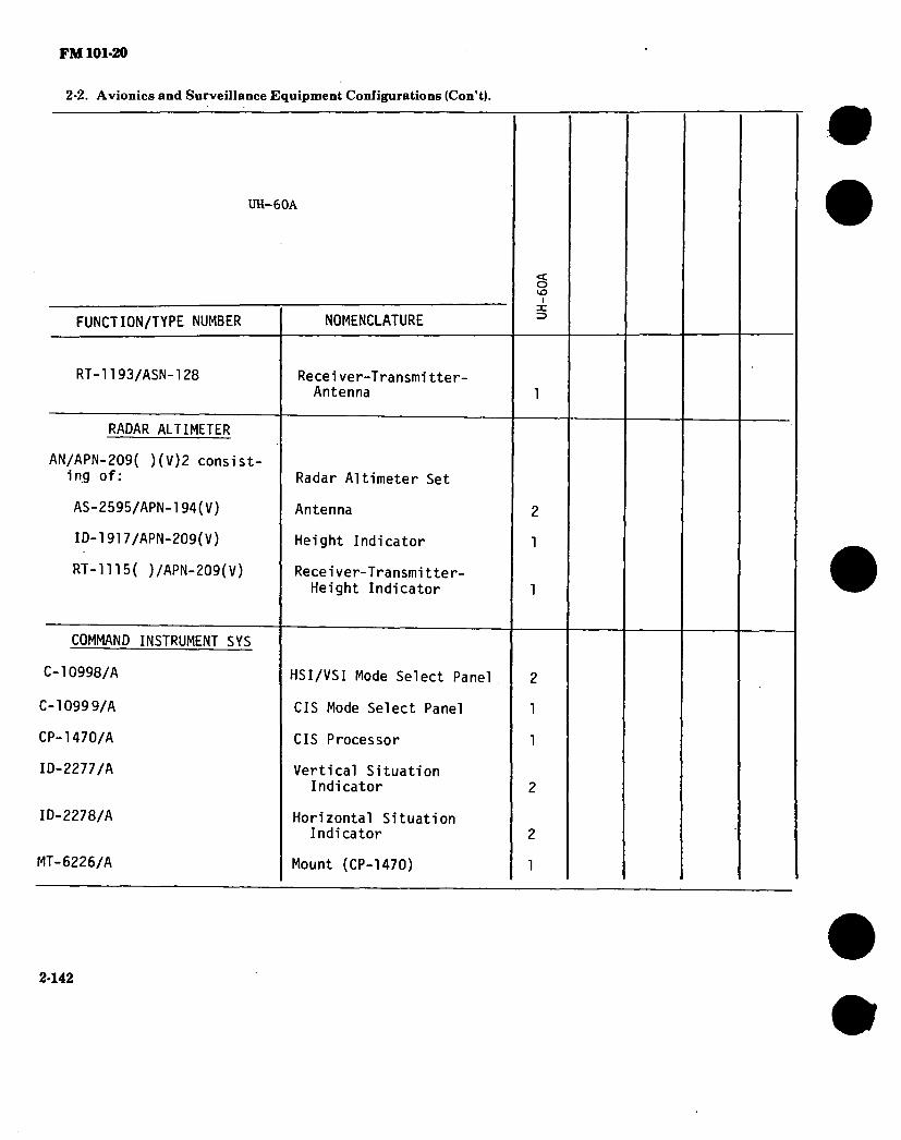
FM 101-20
2-2. Avionics and Surveillance Equipment Configurations (Con’t).
UH-60A
FUNCTION/TYPE NUMBER
RT-1193/ASN-l28
RADAR ALTIMETER
AN/APN-209( )(V)2 consist- ing of:
AS-2595/APN-194(V)
ID-1917/APN-209(V)
RT-1115( )/APN-209(V)
COMMAND INSTRUMENT SYS
C-10998/A
C-10999/A
CP-1470/A
ID-2277/A
ID-2278/A
MT-6226/A
NOMENCLATURE
Recei ver-T ransmi tter- Antenna
Radar Altimeter Set
Antenna
Height Indicator
Recei ver-Transmi tter- Height Indicator
HSI/VSI Mode Select Panel
CIS Mode Select Panel
CIS Processor
Vertical Situation Indicator
Horizontal Situation Indicator
Mount (CP-1470)
< o kO
2-142

FM 101-20
2-2. Avionics and Surveillance Equipment Configurations (Con’t).
. UH-60A
FUNCTION/TYPE NUMBER
IDENTIFICATION
RT-1296/APX-100
AS-3528/A
MT-3949A/U
KIT-1A/TSEC
ATTITUDE INDICATING
CN-1314/A
RATE-OF-TURN-INDICATING
TRU-2A/A
RADAR WARNING
AN/APR-39(V)1 consisting of :
AS-2890/APR-39(V)
AS-2891/APR-39(V)
AS-2892/APR-39(V)
C-9326/APR-39(V)
CM-440/APR-39(V)
NOMENCLATURE
Transponder
IFF Antenna
Mount (KIT-1 A)
IFF Computer
Displacement Gyro
Rate Gyro
Radar Signal Detecting Set
Blade Antenna
Right Spiral Antenna (2 ea)
Left Spiral Antenna (2 ea)
Control
Comparator
O VO
1
2
1
CPO
CPO
CPO
CPO
CPO
CPO
2-143

FM 101-20
2-2. Avionics and Surveillance Equipment Configurations (Con’t).
UH-60A
FUNCTION/TYPE NUMBER
IP-1150/APR-39(V)
R-1838/APR-39(V)
STABILIZATION
AM-7105/A
AM-7106/A
C-10909/A
CN-1552/A
CN-1564/A
CP-1446/A
ID-2279/A
MT-6227/A
TR-322/A
TR-323/A
TR-326/A
70400-06712-042
70901-02002-106
NOMENCLATURE
Indicator
Receiver (2 ea)
Synchro Signal (SAS) Amplifier
Elec Control (Stabilator) Amplifier
Flight Control Panel
Rate Gyro
Rate Gyro
Computer
Stabilator Indicator
Vibration Tray
Air Data Transducer
Air Speed Transducer
Linear Servo Accelerometer
Stab. Position Sensor
Stick Position Sensor
o VO
I
CP0
CPO
2
1
1
1
1
2
1
1
1
2
1
1
2144

FM 101-20
* 2-2. Avionics and Surveillance Equipment Configurations (Con’t).
UH-60A
o vo
i
FUNCTION/TYPE NUMBER
COUNTERMEASURES
AN/ALQ-144(V)1 consisting of:
C-10280/ALQ-144
CY-7611/ALQ-144
T-1360(V)1/ALQ-144
POWER SOURCES
BB-716/A
CV-3701/A
PP-7723/A
MISCELLANEOUS
C-11038/A
J-3766/A
H-250/U
70600-06001-103
NOMENCLATURE
Countermeasures Set
Operators Control Unit CP0
Transit Case CP0
Transmitter CP0
Battery
Power Converter
Battery Charger
Retransmission Control
Audio Interface Unit 1
Troop Commanders Handset 1
Troop Commanders Antenna 1
2-146

FM 101-20
2-2. Avionics and Surveillance Equipment Configurations (Con’t).
NOTES:
1. The AN/ARC-115 was replaced by the RT-1354/ARC-186 beginning with FY 81 production aircraft (81-23547). However, they are interchangeable so either may be installed but not both.
2. Used as the VHF/AM, VHF/FM #2 and ADF sense antenna. 3. Either provisions for the KY-28 (including C-8157) or the KY-58 (including Z-AHP
and Z-AHQ) are installed but not both.
*
APPLICABLE AIRCRAFT AVIONICS MANUALS:
TM 11-1520-237-23-1 TM 11-1520-237-23-2 TM 11-1520-237-23-3 TM 11-1520-237-23P
2-146

FM 101-20
2-3. Aircraft Armament.
The following aircraft armament subsystems and related components are either in the Research and Development state, or have been type classified for field usage.
2-4. Aircraft Armament Application.
ARMT SS AIRCRAFT APPLICATION
M5
MISAI
M19
M21
M22 ^
M23
M27
M35
M28A1
M28A2
M28A3
M24
M41
M56
M65
XM97E1
M128
M136 ^
M138
UH-1 B M H
X
X
X
AH-1 G S* S# SM
X X X XV
X
X n X
XXX
X
X
X X
X X
OH-6A OH-58 A C
Vv
X
CH-47 A B C D
X X
X X X X
AH-64A A
s-¥ (A n~ if (IVAVV0'
S' # (äH'K C?m)) 2-147

FM 101-20
2-4. Aircraft Armament Application (Con’t).
ARMT SS AIRCRAFT APPLICATION A
M156
M158A1
M200A1
XM260
XM261
M230
HMMS 1/
B
X
X
X
UH-1 M
X
X
X
H AH-V v"
G S* S# S##
X X
X X
X X
X X
AH-64A
X
X
X
"■AH-IS (MOD) from AH-1G models
#AH-1S new production
AH-1S modernized from AH-1S (MOD)
1/ Hellfire Module Missile System (HMMS)
SOURCE: (ARRCOM) DRSAR-MAG-SD (MICOM) DRCPM-RK (MICOM) DRCPM-HF
m ■ i
2-148
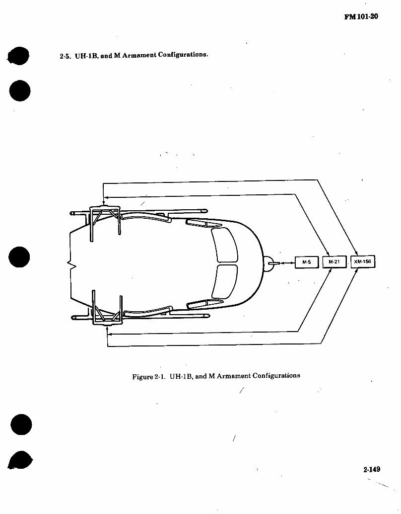
FM 101-20
2-5. UH-1B, and M Armament Configurations.
XM-156 M-21 M-5
Figure 2-1. UH-1B, and M Armament Configurations
2-149

FM 101-20
AMMUNITION TRANSITION CHUTE
AMMUNITION CHUTE COVER
AMMUNITION BOOSTER ASSEMBLY
FRONT AMMUNITION CHUTE ASSEMBLY
REAR AMMUNITION CHUTE ASSEMBLY
©»«J AMMUNITION l(
ROTARY AMMUNITION
^ CAN
CHUTE RETAINER
SERVO-AMPLIFIER JUNCTION BOX
ASSEMBLY
SIGHT MOUNT BRACKET ASSEMBLY
HAND CONTROL SIGHT ASSEMBLY
AMMUNITION CHUTE BRACKET AMMUNITION
CHUTE BRACKET ASSEMBLY ^
AMMUNITION FEED CHUTE ASSEMBLY A
S w L m
4
AIR SPEED TRANSDUCER <7
i
TURRET ASSEMBLY
an
40 MILLIMETER GRENADE LAUNCHER
M 75
TURRET CONTROL PANEL ASSEMBLY
Figure 2-2. M5 Armament Subsystem Components on UH-1B/M (Iroquois) Helikopter
2-150

FM 101*20
2-6. M5 Armament Subsystem, Grenade Launcher.
ARMAMENT SUBSYSTEM: MS APPLICABLE AIRCRAFT - TYPE, MODEL, SERIES: Utility UH-1 B/M AVERAGE PROCUREMENT PRICE: $41,607 TYPE CLASSIFICATION: Standard LOGISTIC CONTROL CODE: A
NOMENCLATURE: Armament subsystem, helicopter, 40 millimeter grenade launcher. Nose mounted turret (1 launcher). M75 Grenade Launcher, air cooled, electric motor driven.
DESCRIPTION: The MS is used on the UH-1 B/M helicopters, and consists of a flexible remote controlled, servo-power driven gun turret mounted in the nose of the UH-1 B/M helicopters. The turret incorporates one M75 grenade launcher. Linked ammunition is stored in a rotary ammo drum in the cargo hook hole, pulled through a flexible chute by an ammo booster, and fed to the grenade launcher. The system also has a box feed system in addition to the rotary AMMO drum. A master armament control panel is located in the instrument console and is accessible to both the pilot and copilot gunner. A flexible hand control sight assembly mounts above the co-pilot’s seat from which the co-pilot can sight and fire the system. The subsystem can also be fired in the stow position by either the pilot or co-pilot by means of a trigger switch on both cyclic stick grips. In this mode, the turret is flexible in elevation. An MWO has been applied to the subsystem to give the sight lead angle compensation. A dual range reticle has been applied for more accuracy at long range.
CHARACTERISTICS: EFFECTIVE RANGE: ELEVATION/DEPRESSION : MUZZLE VELOCITY: RATE OF FIRE: TRAVERSE: EMPTY WT: Box Fed: 233 lbs
Rotary Drum Fed: 223 lbs
AMMUNITION: TYPE: CAPACITY: SIGHTING:
1500 meters + 15°, -35° 790 FPS 230 SPM 60° right and left LOADED WT: 335 lbs (*150 rds)
459 lbs (**300 rds)
Linked 40mm ammunition. *150 rds **300 rds respectively Reflex type: gunner/co-pilot operated in elevation and deflection.
\ \ \
MAINTENANCE AND SUPPLY: a. Maintenance
Instruction: b. Repair parts: c. Special tools: d. Shop sets: Not Applicable
AVUM AVIM and Depot TM 9-1010-207-12 Support TM 9-1010-207-35 TM 9-1010-207-12,20P 34P TM 9-1010-207-12,20P 34P
* 2-151

FM 101-20
2-6. M5 Armament Subsystem, Grenade Launcher (Con’t).
MODIFICATION DATA REQUIRED FOR INSTALLATION, FUNDING, CONTROLS, AND OPERATING INSTRUCTIONS:
KIT NSN A 1560-00-753-7294 C 1010-00-738-5811 *RAC 1560-00-936-4334
PUBLICATION NICP MWO 55-1520-211-34/33 B17 TM 9-1010-207-12 B14 MWO 55-1520-211-30/32 B17
FUND REQUIREMENTS DA Allocated DA Allocated DA Controlled
Initial issue of kits is DA Controlled and Procurement Appropriation Army (PAA) funded. Repair parts other than initial MWO procurement items are stock funded.
*RAC — Rotary Ammo Can — Required to upgun the M5 subsystem.
Operational instructions for subsystem can be found in TM 66-1520-220 series manual.
* 2-152

FM 101-20
#
N
J
n1
Figure 2-3. MISAI Armament Subsystem
)
«27,
% ** «i»
T
Figure 2-4. MISAI Armament Subsystem
2-153

FM 101-20
2-7. MISAI Armament Subsystem.
ARMAMENT SUBSYSTEM: MISAI APPLICABLE AIRCRAFT TYPE MODEL AND SERIES: Attack helicopter AH-1 SERIES AVERAGE PROCUREMENT PRICE: $20,070 TYPE CLASSIFICATION: Standard LOGISTIC CONTROL CODE: A
#
NOMENCLATURE: Armament pod, helicopter, 7.62mm machine gun: high-rate
DESCRIPTION: The MISAI armament pod consists of one 7.62mm automatic gun, M134, in a cylindrical pod mounted on the inboard wing stores of the aircraft. The pod stores 1500 rounds of ammunition in a linkless feed system. The gun is electrically driven at either low rate, 2000 shots per minute, or high rate, 4000 shots per minute. The pod is self-powered by a self contained battery with a power start feature using auxiliary aircraft power for more starting torque. The pod is rigidly mounted and aiming is accomplished by maneuvering the aircraft.
CHARACTERISTICS: MAXIMUM EFFECTIVE RANGE: ELEVATION: MUZZLE VELOCITY: RATE OF FIRE: TRAVERSE: EMPTY WT: 240 lbs AMMUNITION:
TYPE: CAPACITY: SIGHTING:
1500 meters Fixed 2750 FPS 2000 or 4000 SPM Fixed LOADED WT: 320 lbs
Linked 7.62mm 1500 rds M73 Reflex type
MAINTENANCE AND SUPPLY: Maintenance instruction: Repair parts: Special tools Shop sets: Not Applicable
AVUM TM 9-1005-257-12 TM 9-1005-257-20P TM 9-1005-257-20P
AVIM and Depot Support TM 9-1005-257-35 35P 35 and 35P
MODIFICATION DATA REQUIRED FOR INSTALLATION, FUNDING, CONTROLS, AND OPERATING INSTRUCTIONS:
KIT NSN PUBLICATION NICP
1005-00-832-7498 JM 9-1005-257-12 B14 FUND REQUIREMENTS DA controlled
Operational instructions for subsystem can be found in TM 55-1520-221-10.
2-154

FM 101-20
v &
If %*
m.
Figure 2-5. M19 Dispenser
2-155

FM 101-20
2-8. M19 Dispensing Subsystem.
Dispenser: M19 Aircraft: UH-l/B/H Average procurement price: $1,500 Application: Flares per dispenser: Weight:
Overall Length:
Width: Height: Rate of Ejection:
Elevation: Transverse: Sighting: Status: DODIC:
One in troop cargo compartment 24 Flares, MK45 w/adapter 150 lbs empty 822 lbs with flares 118 inches w/snout extended 81.0 inches w/snout collapsed 16.0 inches 46.0 inches Manually controlled
Attitude of aircraft Attitude of aircraft Visual assessment LP L106
DESCRIPTION: MK45 Flares are loaded into the dispenser with pull cable assembly disk inserted in the overhead track. Immediately prior to launch, the flare safety pin is pulled. The flare to be launched is positioned so that its base is stopped by the foot on the base tray. The operator then pushes the upper portion of the flare outward. The base of the flare then swings outward, providing sufficient force on the pull cable assembly to shear a pin, permitting the flare to fall free. A pull pin is provided for manual jettisoning of the load and flare rack.
MK45 Flare, Aircraft, Parachute.
Illumination: Burn time: Weight: Overall Length: Diameter: Adjustable Time: Status: Logistic Control Code: DODIC:
DESCRIPTION:
2,000,000 candlepower 210 seconds 28 lbs 36 inches 4.87 inches Mechanical/pyrotechnic fuze Std
B 1370-L424
Prior to launch, the fuze is set for the desired drop delay (in feet below the aircraft), and the safety pin removed. When launched, the weight of the falling flare against the pull
cable exerts sufficient force to break a shear pin to initiate the delay and subsequently ignite the fuze. At the desired time, the parachute/candle assembly is ejected from the outer container, and activated. Near the end of burning, the parachute is collapsed and the spent flare falls rapidly to the ground.
2-156

FM 101-20
HC
SS\\ V'- \
u \)
n >x
'ß^F «S
7?
X J JU / m
I L*>
(ZI
Figure 2-6. M21 Armament Subsystem Installed on UH-1B/M (Iroquois) Helicopter
<3
2-157

FM 101-20
2-9. M21 Armament Subsystem
ARMAMENT SUBSYSTEM: M21 APPUCABLE AIRCRAFT - TYPE, MODEL, SERIES: Utility aircraft, UH-1B.M AVERAGE PROCUREMENT PRICE: $51,897 TYPE CLASSIFICATION: Standard LOGISTIC CONTROL CODE: A
NOMENCLATURE: Armament subsystem, helicopter, 7.62mm twin high rate machine gun with 2.75 inch rocket launchers.
DESCRIPTION: The M21 armament subsystem combines the 7.62 mm, high rate of fire machine gun Ml34 and the 2.75 inch Folding Fin Aerial Rocket (FFAR), M158A1 launchers. The subsystem consists of two remotely controlled, power operated, flexible pylons, each mounting one 7.62mm machine gun Ml34 and provisions for a non-flexible rocket pod containing seven 2.75 inch FFAR. The rocket launcher installation on each pylon contains associated hardware to fire the rockets and to jettison the launcher. Linked 7.62mm ammunition is stowed inboard and transported to the guns through flexible chuting. A flexible sighting system enables the copilot to remotely aim and fire the machine guns. The pilot may fire either the rockets or the machine guns when in stow position using a fixed sight. The subsystem utilizes all standard 7.62mm NATO ammunition and 2.75 inch rockets applicable to the Ml58A1 launcher.
CHARACTERISTICS: MAXIMUM EFFECTIVE RANGE: Machine Gun: 1500 meters Rocket: 3000 meters RATE OF FIRE: MUZZLE VELOCITY: TRAVERSE:
SIGHTING:
EMPTY WEIGHT: 804 lbs AMMUNITION: TYPE: CAPACITY: ROCKETS: TYPE: CAPACITY:
ELEVATION DEPRESSION. Machine Gun: +10° to -85° Rocket Launcher: Boresight only 2000 or 4000 SPM 2750 FPS Machine guns, inboard 12°, outboard 70° in azimuth from longitudinal axis Pilot-manual reflex type for machine gun and rocket. Copilot/gunner flexible reflex type sight for machine gun only LOADED WEIGHT: 1179.2 lbs
Linked 7.62MM 6000 rds
2.75 inch FFAR 14 RDS
2-158

FM 101-20
2-9. M21 Armament Subsystem (Con’t).
MAINTENANCE AND SUPPLY: Maintenance Instruction: Repair Parts: Special Tools: •To be published
AVUM TM 9-1090-202-12 TM 9-1090-202-20P TM 9-1090-202-20P
AVIM and Depot Support TM 9-1090-202-35 -34P* -34 P*
MODIFICATION DATA REQUIRED FOR INSTALLATION, FUNDING, CONTROLS, AND OPERATING INSTRUCTIONS:
KIT NSN A 1560-00-915-8931 B 1560-00-915-8933 C 1090-00-923-5971
•1560-00-923-3182
PUBLICATION NICP MWO 55-1520-211-30/8 B17 TM 55-1520-211-20/5 B17 TM 9-1090-202-12 B14 MWO 55-1520-211-30/12 B17
FUND REQUIREMENT DA Allocated DA Allocated DA Allocated Free Issue
Initial issue of kits is DA Allocated, DA Controlled, and Procurement Appropriation Army (PAA) funded. Repair parts other than initial MWO procurement items are stock funded.
Operational instructions for subsystem can be found in TM 55-1520-220 series manual.
•Sight Stow Bracket
In addition to the provisions:
required if not previously installed,
above, these modifications can be installed only in aircraft which have the following
M3/M6 “A” Kit, FSN 1560-9604043, publication MWO 55-1520-22140/4, NICP B17, DA Allocated M16 “A” Kit, FSN 1560-918-7007, publication MWO 55-1520-211-30/4, NICP B17.
Initial issue of rocket launchers, M158A1, FSN 1055-00-805-0689, is provided with subsystem.
2-159

FM 101-20
Figure 2-7. M22 Armament System Installed on UH-1B (Iroquois) Helicopter
2-160

FM 101-20
2-10. M22 Armament Subsystem, Guided Missile Launcher.
ARMAMENT SUBSYSTEM: M22 APPLICABLE AIRCRAFT - TYPE, MODEL, SERIES: UH-1B AVERAGE PROCUREMENT PRICE: $34,000 (estimate) TYPE CLASSIFICATION: Standard LOGISTIC CONTROL CODE: A
NOMENCLATURE: Armament subsystem, helicopter, guided missile launcher.
\
DESCRIPTION: The M22 system includes a guidance control box, missile selector box, control stick, and six launchers. Items required to complete the airljorne subsystem are an MK-8 pilots sight, ' a stabilized optical 6X sight for the gunner, two' booms for mounting launchers (three per ’ side), and jettisoning equipment. An adaption kit is required for attachment of system •
components to the helicopter. Operation of the subsystem requires close coordination between pilot and co-pilot/gunner.
CHARACTERISTICS: EFFECTIVE RANGE: ELEVATION: MISSILE VELOCITY: RATE OF FIRE: TRAVERSE: EMPFY WT: 272 lbs MISSILE CAPACITY: AMMO TYPE: SIGHTING:
DATA:
3000 meters Missile directed in flight by wire command link. 180 meters/second cruise As selected by pilot/gunner. Missile directed in flight by wire command link. LOADED WT: 650 lbs 6 missiles (3 each side) AGM-22B Missile, 63 lbs each Pilot MK8 lighted roof mounted. Co-pilot/gunner 6x42 power anti-collision binocular (M-55) or monocular (M-58.) Complete outboard stores are jettisonable, or each missile.
MAINTENANCE AND SUPPLY: Maintenance instruction: AVUM AVIMsupport
TM 9-1400-461-20 and-35 Repair parts: TM 9-1400-461-12P and -35P Special tools: TM 9-1400461-12P and -35P Shop sets: TM 9-1400461-12P and-35P
MODIFICATION DATA REQUIRED FOR INSTALLATION, FUNDING, CONTROLS, AND OPERATING
INSTRUCTIONS: Operational Instructions contained in TM 55-1520-219-10.
2-161

FM 101-20
2-11. UH-1H Armament Configurations.
*4/ ////
>ni
¡I o
•DOOR MOUNTED WEAPONS ONLY
Figure 2-8. UH-1H Armament Configurations
2-162

Figure 2-9. M23 Armament Subsystem on UH-1H (Iroquois) Helicopter
2-163
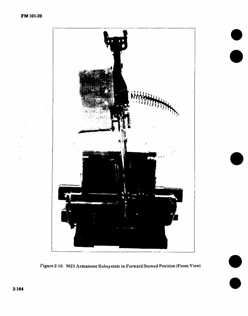
FM 101-20
* * * ? » m . a m 11 m w i « / *
Figure 2-10. M23 Armament Subsystem in Forward Stowed Position (Front View)
2-164
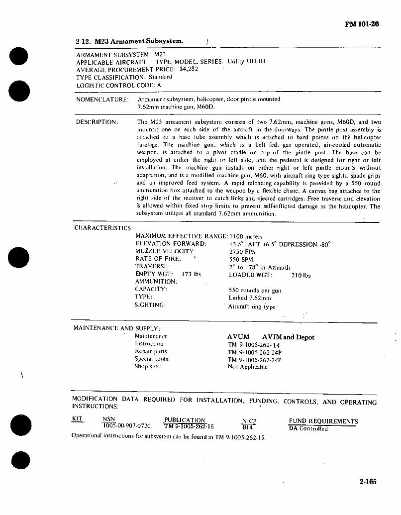
FM 101-20
2-12. M23 Armament Subsystem. ) ARMAMENT SUBSYSTEM: M23 APPLICABLE AIRCRAFT TYPE, MODEL, SERIES: Utility UH-lH AVERAGE PROCUREMENT PRICE: $4,282 TYPE CLASSIFICATION: Stundurd LOGISTIC CONTROL CODE: A
NOMENCLATURE: Armament subsystem, helicopter, door pintle mounted 7.62mm machine gun, M60D.
DESCRIPTION: The M23 armament subsystem consists of two 7.62mm, machine guns, M60D, and two mounts; one on each side of the aircraft in the doorways. The pintle post assembly is attached to a base tube assembly which is attached to hard points on the helicopter fuselage. The machine gun, which is a belt fed, gas operated, air-cooled automatic weapon, is attached to a pivot cradle on top of the pintle post. The base can be employed at either the right or left side, and the pedestal is designed for right or left installation. The machine gun installs on either right or left pintle mounts without adaptation, and is a modified machine gun, M60, with aircraft ring type sights, spade grips and an improved feed system. A rapid reloading capability is provided by a 550 round ammunition box attached to the weapon by a flexible chute. A canvas bag attaches to the right side of the receiver to catch links and ejected cartridges. Free traverse and elevation is allowed within fixed stop limits to prevent self-inflicted damage to the helicopter. The subsystem utilizes all standard 7.62mm ammunition.
CHARACTERISTICS: MAXIMUM EFFECTIVE RANGE: 1100 meters ELEVATION FORWARD: MUZZLE VELOCITY: RATE OF FIRE: TRAVERSE: EMPTY WGT: 173 lbs AMMUNITION: CAPACITY: TYPE:
SIGHTING:
+3.5°, AFT +6.5° DEPRESSION -80° 2750 FPS 550 SPM 2° to 178° in Azimuth LOADED WGT:
550 rounds per gun Linked 7.62mm
Aircraft ring type
210 lbs
MAINTENANCE AND SUPPLY: Maintenance Instruction: Repair parts: Special tools: Shop sets:
AVUM AVIM and Depot TM 9-1005-262-14 TM 9-1005-262-24P TM 9-I005-262-24P Not Applicable
MODIFICATION DATA REQUIRED FOR INStALLATION INSTRUCTIONS:
FUNDING, CONTROLS, AND OPERATING
KIT NSN PUBLICATION NICP 1005-00-907-0720 TM 9-1005-262-15 TTÏT
Operational instructions for subsystem can be found in TM 9-1005-262-15
FUND REQUIREMENTS DA Controlled ’
2-165

FM 101-20
HELICOPTER REFLEX SIGHT M70
SEE DETAIL D
SEE DETAIL A
« A DETAIL
¡2>
SEE DETAIL
SEE DETAIL C
RAM AIR DUCT
DETAIL C
V, MOUNT ASSEMBLY GUN ASSEMBLY
\ D DETAIL
DETAIL B AV 012373
Figure 2-11. M27 Armament System Components (OH-6A Application)
2-166

FM 101-20
HELICOPTER REFLEX SIGHT M70
i
DETAIL D
SEE DETAIL D
AN
y \ SEE DETAIL C
SEE DETAIL B
is
GUN ASSEMBLY
MOUNT I ASSEMBLY RAM AIR DUCT
DETAIL DETAIL C
DETAIL A
SEE DETAIL
Figure 2-12. M27 (OH-58A Application)
2-167

FM 101-20
2-13. M27 Armament Subsystem.
ARMAMENT SUBSYSTEM: M27 APPLICABLE AIRCRAFT - TYPE, MODEL, SERIES: OH-6A, OH-58A AVERAGE PROCUREMENT PRICE: $25,439 TYPE CLASSIFICATION: Standard LOGISTIC CONTROL CODE: B
NOMENCLATURE: Armament subsystem, helicopter, 7.62mm machine gun; high rate M27
DESCRIPTION: The M27 armament subsystem mounts the high rate of fire 7.62mm machine gun Ml34. The subsystem consists of a single, remote controlled, semi-flexible mount which supports the machine gun, Ml34, on the left (port) side of the OH-6 and OH-58 helicopters. Linked 7.62mm ammunition is stored inboard and transported to the gun through fixed chuting. A flexible, mechanically linked sighting system enables the pilot to remotely aim and fire the machine gun. The weapon subsystem*is flexible in elevation and depression only, being fixed in azimuth. The aircraft must be aimed by the pilot for target engagement. The armament subsystem is adaptable to the helicopter by means of quick release attachments. Complete internal provisions are incorporated in the production aircraft to accept the armament subsystem without modifications. The weapons subsystem complements weapon systems currently employed in the field.
CHARACTERISTICS: MAXIMUM EFFECTIVE RANGE: ELEVATION/DEPRESSION:
MUZZLE VELOCITY: RATE OF FIRE. TRAVERSE: EMPTY WT: 100 lbs AMMUNITION: CAPACITY: TYPE: SIGHTING.
1500 meters OH-6A +10°, to -24° OH-58 A +5 1/2° to-20° 2750 FPS 2000 or 4000 SPM None LOADED WT: 234 lbs
2000 rds. Linked 7.62mm Pilot M70 reflex type
MAINTENANCE AND SUPPLY:
Maintenance Instruction: Repair parts: Special tools: Shop sets:
AVUM TM 9-1005-298-12 TM 9-1005-298-20P TM 9-1005-298-20P Not Applicable
AVIM and Depot -34 -35P -35P
DMWR 9-1005-298
mSTRUCTIONS DATA REQUIRED F0R ILLATION, FUNDING, CONTROLS, AND OPERATING
KIT C
NSN PUBLICATION 1005-00-933-6242 TM 9-1005-298-12
NICP B14
FUND REQUIREMENT DA Allocated
2-168

FM 101-20
$F= à
Figure 2-13. M35 Armament Subsystem
/ 2-169

FM 101-20
2-14. M35 Armament Subsystem.
ARMAMENT SUBSYSTEM: M35 APPLICABLE AIRCRAFT - TYPE. MODEL. SERIES: AH- 1G AVERAGE PROCUREMENT PRICE: S44.865 TYPE CLASSIFICATION: Standard 7
LOGISTIC CONTROL CODE: B
NOMENCLATURE: Armament subsystem helicopter. M35
DESCRIPTION: The M35 Subsystem has a 20mm Gatling type gun mounted on the inboard station of the . left hand wing. The gun is basically a modified M61A1 gun with shorter barrels and a
declutching feeder. It is designated the 20mm automatic gun. Mll>5. It automatically clears itself of all live rounds at the end of each burst without dumping live rounds overboard. The gun is a fixed mount and is pilot controlled. Controls are provided for the co-pilot/gunner to fire the weaspon. if necessary. Two ammunition cans (one on either side) are faired into the fuselage at the base of the stub wings.
CHARACTERISTICS: EFFECTIVE RANGE: ELEVATION: MUZZLE VELOCITY: RATE OF FIRE: TRAVERSE:
3000 meters Attitude of aircraft 3380 FPS 650-850 SPM Attitude of aircraft
EMPTY WT: AMMUNITION: CAPACITY: TYPE: SIGHTING:
555 lbs (approx) LOADED WT: 1187 lbs (approx)
950 rds Linked 20mm - M56 HEI and XM220 TPT M73 reflex type
MAINTENANCE AND SUPPLY:
Maintenance Instruction: Repair parts: Special tools: Shop sets:
Organizational TM 9-1005-299.12 TM 9-1005-299-20P TM 9-1005-299-20P Not Applicable
Direct, General, and Depot Support TM 9-1005-299-34 -35P* -34 and -35P*
MODIFICATION DATA REQUIRED FOR INSTALLATION, FUNDING, CONTROLS, AND OPERATING INSTRUCTIONS:
K¡! NSN PUBLICATION NICP A 7350-00-246-4744 MWO 55-1520-22140/4 B17 C 1005-00-133-8193 TM 9-1005-299-12 B14
FUND REQUIREMENT COBRA Project Manager
(DRCPM-CO)
Operational instructions are contained in TM 55-1520-221-10.
•To be published as a -34P
2-170

FM 101-20
2-15. M28A1 Armament Subsystem.
ARMAMENT SUBSYSTEM: M28AI APPLICABLE AIRCRAFT - TYPE, MODEL, SERIES: AH-lG AVERAGE PROCUREMENT PRICE: $95,067 TYPE CLASSIFICATION. Standard LOGISTIC CONTROL CODE: A
NOMENCLATURE: Armament subsystem, helicopter, 7.62mm machine gun, 40mm grenade launcher.
DESCRIPTION: The M28A1 armament subsystem is an electrically controlled, hydraulically operated, dual weapon that provides wide angle coverage and rapid fire for the AH-lG Hueycobra. The M28A1 armament subsystem consists of a power operated chin turret, mounting the 7.62 mm machine gun M134 on the right and the 40mm grenade launcher M129, on the left. Ammunition is stored in the ammunition bay and moved to the turret through fixed and flexible chuting. Fire control equipment is located at the gunner/co-pilot station and allows the gunner to train the weapons in azimuth and elevation. Provisions are made for the pilot to fire the weapons in the stow position. The system provides the AH-lG Hueycobra with area and point fire for attack on personnel and lightly armored and unarmored materiel targets during escort and armed reconnaissance missions.
CHARACTERISTICS: MAXIMUM EFFECTIVE RANGE:7.62mm 1500 meters;40mm 1500 meters ELEVATION/DEPRESSION :
MUZZLE VELOCITY.
Variable elevator traverse, +12° to +17.5° and depression —50°.
Machine gun 2750 FPS 40mm Grenade launcher
RATE OF FIRE: TRAVERSE: EMPTY WT: 7.62mm and
790 FPS 7.62mm - 2000 or 4000 SPM, 40mm - 420 SPM 114° left and right of longitudinal axis of AH-lG
40mm 447 lbs LOADED WT : 897 lbs
AMMUNITION: CAPACITY:
Maximum 4000 rds for Ml34,300 rds for TYPE: Ml 29.
Linked 7.62mm and 40mm. SIGHTING : Pilots reflex sight M73, lighted reticle and manual
range adjustment. Gunner sight is a flexible reflex
sight with automatic air speed compensation.
2-171

FM 101-20
2-15. M28A1 Armament Subsystem (Con’t).
MAINTENANCE AND SUPPLY:
Maintenance Instruction: Repair parts: Special tools: Shop sets:
AVUM Avim and Depot TM 9-1090-203-12; -34 TM 9-1090-203-20P; -34P TM 9-1090-203-12 and 20P; -34 and -34P Not Applicable DMWR 9-1090-202-2
DMWR 9-1090-203-1
MODIFICATION DATA REQUIRED FOR INSTALLATION, FUNDING, CONTROLS, AND OPERATING INSTRUCTIONS:
KIT NSN 1090-00-134-3071
PUBLICATION TM 9-1090-203-12
N1CP B14
FUND REQUIREMENTS DA Controlled
AV 000149
i //
i Á
rcYl/ fcoCOC:
R U - “TK" ' I I I
D> l Í r'
.J
M28A1
Figure 2-14. M28A1 Armament Subsystem
2-172

FM 101-20
2-16, M28A2 Armament Subsystem.
ARMAMENT SUBSYSTEM: M28A2 APPLICABLE AIRCRAFT - TYPE, MODEL, SERIES: AH-1S (MOD) AVERAGE PROCUREMENT PRICE: $183,567 TYPE CLASSIFICATION: Standard
NOMENCLATURE: Armament subsystem, helicopter, 7.62mm machine gun, 40mm grenade launcher.
DESCRIPTION: The M28A2 armament subsystem is an electrically controlled, hydraulically operated, dual weapon that provides wide angle coverage and rapid fire for the AH-1S. The M28A2 armament subsystem consists of a power operated chin turret, mounting the 7.62nm machine gun Ml34 and on the right and the 40mm grenade launcher M129 on the left. Ammunition is stored in the ammunition bay and moved to the turret through fixed and flexible chuting. The M28A2 is controlled in the flexible mode by either the gunner or pilot by use of the Ml28 helmet sight subsystem. The gunner can also direct fire by using the telescopic sight unit. The M-73 sight gives the pilot the ability to fire the turret weapons in the stowed posi- tion. The system provides the AH-1S with area and point fire for attack on personnel and lightly armored and unar— mored materiel targets during escort and armed reconnais- sance missions.
CHARACTERISTICS
MAXIMUM EFFECTIVE RANGE: 7.62mm 1500 meters; 40mn 1500 meters
ELEVATION/DEPRESSION: +20° — SO0 variable with traverse MUZZLE VELOCITY: Machine gun 2750 FPS 40mm Grenade launcher
790 FPS RATE OF FIRE: 7.62mm - 2000 or 4000 SPM, 40mm - 420 SPM
TRAVERSE: 110° left and right of longitudinal axis
EMPTY WT: 7.62mm and 40mm 447 lbs LOADED WT: 897 lbs
AMMUNITION: CAPACITY.
TYPE:
SIGHTING:
Maximum 4000 rds for each M 134, 300 rds for each Ml29.
Linked 7.62rrm and 40mm.
Ml28 helmet sight subsystem M73 reflex sight M65TOW missile subsystem
2-173
i

FM 101-20
2-16. M28A2 Armament Subsystem (Con’t).
MAINTENANCE AND SUPPLY:
Maintenance Instruction: Repair parts: Special tools: Shop sets:
AVUM TM 9-1090-203-12-1 TM 9-1090-203-20P-1 TM 9-1090-203-12-1 and 20P-1 Not Applicable
AVIM and Depot -34-1 -34P-1
Not Applicable
MODIFICATION DATA REQUIRED FOR INSTALLATION, FUNDING, CONTROLS, AND OPERATING INSTRUCTIONS:
KIT NSN PUBLICATION 1090-00-081-1046 TM 9-1090-203-12-1
NICP FUND REQUIREMENTS B14 DA Controlled
t »
! « I
V:-4: C- rr
Figure 2-15. M28A2 Armament Subsystem
2-174

FM 101-20
2-17. M28A3 Armament Subsystem.
ARMAMENT SUBSYSTEM. M28A3 APPLICABLE AIRCRAFT - TYPE. MODEL, SERIES: AH-IS (new production) AVERAGE PROCUREMENT PRICE: $183,567 TYPE CLASSIFICATION: Standard
NOMENCLATURE: Armament subsystem, helicopter, 7.62mm machine gun, 40mm grenade launcher.
DESCRIPTION: The M28A3 armament subsystem is an electrically controlled,
hydraulically operated, dual weapon that provides wide angle coverage and rapid fire for the AH-1S. The M28A3 armament subsystem consists of a power operated chin turret, mounting the 7.62nm machine gun M134 and on the right and the 4Chim grenade launcher M129 on the left. Anmunition is stored in the ammunition bay and moved to the turret through fixed and
flexible chuting. The M28A3 is controlled in the flexible mode by either the gunner or pilot by use of the M136 helmet sight subsystem. The gunner can also direct fire by using
the telescopic sight unit. The M-73 sight gives the pilot the ability to fire the turret weapons in the stowed posi- tion. The system provides the AH-1S with area and point fire for attack on personnel and lightly armored and unar- mored materiel targets during escort and armed reconnais- sance missions.
CHARACTERISTICS: MAXIMUM EFFECTIVE RANGE: 7.62mm 1600 meters; 40mm 1500 meters ELEVATION/DEPRESSION: +20° — 50° variable with traverse MUZZLE VELOCITY: Machine gun 2750 EPS 40mm Grenade
launcher 790 FPS RATE OF FIRE: 7.62mm ■ 2000 or 4000 SPM, 40mm - 420 SPM TRAVERSE: 110° left and right of longitudinal axis EMPTY WT: 7.62mm and 40mm 447 lbs LOADED WT: 897 lbs
AMMUNITION: CAPACITY:
TYPE: SIGHTING:
Maximum 4000 rds for each M134, 300 rds for eachM129 Linked 7.62mm and 40mm M128 helmet sight subsystem M73 reflex sight M65TOW misxsile subsystem
DIFFERENCES:
The M28A3 Subsystem features edge lighting on the pilots and gunners control panel.
2-175

FM 101-20
2-17. M28A3 Armament Subsystem (Con’t).
MAINTENANCE AND SUPPLY:
Maintenance Instruction: Repair parts: Special tools: Shop sets:
AVUM TM 9-1090-203-12-2 TM 9-1090-203-20P-1 /-2 TM 9-1090-203-12-2, -20P-1 and -20P-2 Not Applicable
AVIM and Depot -34-1,34-2 -34-1, 34P-2
Not Applicable
MODIFICATION DATA REQUIRED FOR INSTALLATION, FUNDING, CONTROLS, AND OPERATING INSTRUCTIONS:
KIT NSN PUBLICATION NICP
- 1090-01-030-0095 TM 9-1090-203-12-2 B14
FUND REQUIREMENTS
DA Controlled
Illustration to be furnished next revision.
Figure 2-16. M28A3 Armament subsystem
2-176

FM 101-20
V U
b Kv.\ ,
, 0/———>v H ài K
7
/:
k VJ
H>,
K (■■■■)
V /
o vv
T/ e
/ / V - -. O v
j '*<1
$ / 0
M24
r/~
M41
&
Figure 2-17 M24 and M41 Armament Subsystems Installed on CH-47 (Chinook) Helicopter
2-177

FM 101-20
2-18. M24Annament Subsystem.
ARMAMENT SUBSYSTEM: M24 APPLICABLE AIRCRAFT - TYPE, MODEL, SERIES: CH47A AVERAGE PROCUREMENT PRICE: $3722 TYPE CLASSIFICATION: Standard LOGISTIC CONTROL CODE: A
NOMENCLATURE: Armament subsystem, helicopter, door pintle mounted 7.62mm M60D machine gun
DESCRIPTION: The subsystem consists of two machine guns, M60D, and two mounts, one mount on each side of the aircraft. The subsystem mount assemblies are located in the cabin doorway and forward escape hatch of the CH-47 type helicopter. The subsystem contains mechanical safeties and stops to preclude accidental damage to the aircraft due to inadvertent firing of the guns into the airframe. The mount assemblies are designed so that the left and right cams and stops cannot be installed and used incorrectly on the opposite side of the aircraft. The machine gun with bipod has the capability of being quickly removed from the mount and used as a ground weapon. A link and brass ejection control bag is attached to the right side of each machine gun to prevent the cartridge cases and links from being ejected into the paths of the rotor blades or turbine engine intake.
CHARACTERISTICS: MAXIMUM EFFECTIVE RANGE: 1100 meters ELEVATION:
MUZZLE VELOCITY: RATE OF FIRE: TRAVERSE:
EMPTY WT: AMMUNITION: CAPACITY: TYPE: SIGHTING:
97 lbs
Forward +3°, Aft +6.5°, Depression 78° right side, 67° left side 2750 FPS 550 SPM Left gun 71° fwd, 59° aft; right gun 74° fwd, 61° aft LOADED WT: 123 lbs
200 rds per side Linked 7.62mm Ring and post type
MAINTENANCE AND SUPPLY: Maintenance Instructions Repair parts: Special tools: Shop sets:
AVUM AVIM and Depot; TM 9-1005-262-14 TM 9-1005-262-24P TM 9-1005-262-24P Not Applicable
MODIFICATION DATA REQUIRED FOR INSTALLATION, FUNDING, CONTROLS, AND OPERATING INSTRUCTIONS:
None required
KLE NSN PUBLICATION NICP FUND REQUIREMENTS 1005-00-763-1404 TM 9-1005-262-15 B14 DAControUed
Operational instructions for subsystem can be found in TM 9-1005-262-15.
2-178

FM 101-20
2-19. M41 Armament Subsystem.
ARMAMENT SUBSYSTEM: M41 APPLICABLE AIRCRAFT - TYPE, MODEL, SERIES: CH^t7A/B/C AVERAGE PROCUREMENT PRICE: $2,205 TYPE CLASSIFICATION: Standard LOGISTIC CONTROL CODE: A
NOMENCLATURE: Armament subsystem, helicopter, 7.62mm machine gun M60D, ramp mounted, light weight.
DESCRIPTION: The M41 armament subsystem consists of a pintle mount, machine gun M60D, link and brass retainer, ammo box, and gunner’s safety harness. The machine gun M60D, is utilized with positive mechanical stops to limit weapon attitude.
CHARACTERISTICS: MAXIMUM EFFECTIVE RANGE: 1100 meters ELEVATION/DEPRESSION : MUZZLE VELOCITY: RATE OF FIRE. TRAVERSE: WEIGHT: AMMUNITION: CAPACITY:
+ 12.5°,-69 2750 FPS 550 SPM cyclic rate 52° right or left 41 lbs empty, 55 lbs loaded
200 rds TYPE: SIGHTING.
Linked 7.62mm Aircraft ring and post type
MAINTENANCE AND SUPPLY: Maintenance Instruction: Repair parts: Special tools: Shop sets:
AVUM AVUM TM 9-1005-262-14 TM 9-1005-262-24P TM 9-1005-262-24P Not Applicable
MODIFICATION DATA REQUIRED FOR INSTALLATION, FUNDING, CONTROLS, AND OPERATING INSTRUCTIONS:
KIT NSN PUBLICATION NICP FUND REQUIREMENT C 1005-00-087-2046 TM 9-1005-262-24P B14 DA Allocated
Operating instructions are contained in TM 9-1005-262-15.
2-179

Figure 2-18. M56 Mine Dispenser

FM 101-20
2-20. M56 Aircraft Mine Dispersing Subsystem.
ARMAMENT SUBSYSTEM: M56 APPLICABLE AIRCRAFT TYPE, MODEL, SERIES: AVERAGE PROCUREMENT PRICE: $10,640 TYPE CLASSIFICATION: Standard LOGISTIC CONTROL CODE: A
UH: 1H
NOMENCLATURE: Mine dispersing subsystem, aircraft
DESCRIPTION: The M56 is a helicopter mine dispersing subsystem consisting of a US Air Force SUU-I3 dis- penser containing 40 mine canisters. Each canister contains two antitank mines and one XM198 mine ejection charge. A battery is installed in each mine just prior to flight. Firing of the subsystem is controlled by the aircraft crew. Quantity and interval of mine canister firing is controlled from the cockpit. The mines will arm only after both ejection and impact. The minimum altitude for dispensing is 100 feet.
CHARACTERISTICS: LENGTH: DIAMETER: EMPTY WEIGHT: LOADED WEIGHT: CAPACITY: SIGHTING.
90.4 inches 14.5 inches 117 lbs • 660 .lbs
■40 mines None
MAINTENANCE AND SUPPLY: Maintenance Instruction: Repair parts: Special tools: Shop sets
Direct Support TM 9-1345-201-30 TM 9-1345-201-30 TM 9-1345-201-30 Not Applicable
MODIFICATION DATA REQUIRED FOR INSTALLATION, FUNDING, CONTROLS, AND OPERATING INSTRUCTIONS:
Operational instructions contained in TM 9-1345-201-10-1
2-181

FM 101-20
PILOT'S STEERING INDICATOR
TOW ELECTRONIC POWER SUPPLY
TOW MISSLE COMMAND AMPLIFIER
PILOT'S TOW MISSLE STATUS PANEL
GUNNER'S TOW
CONTROL PANEL
. •v
TOW STABILIZATION
CONTROL AMPLIFIER
GUIDED MISSLE LAUNCHER
<3
O
/
TOW TELESCOPIC SIGHT UNIT
SIGHT HAND CONTROL
Figure 2-19. M65 Armament Subsystem (Typical) AH-IS(MOD)
2-182

FM 101-20
2-21. M65 Armament Subsystem.
ARMAMENT SUBSYSTEM: M65 APPLICABLE AIRCRAFT - TYPE, MODEL, SERIES: AH-1S (MOD), AH-1S AVERAGE PROCUREMENT PRICE W/LATT: $795,400 TYPE CLASSIFICATION: Standard LOGISTIC CONTROL CODE: A
NOMENCLATURE: Armament Subsystem, Helicopter, TOW Guided Missile: M65
DESCRIPTION: The M65 Armament Subsystem utilizes optical and infrared means of tracking and guiding the TOW missile to the target. Items that make up the system include the Telescopic Sight Unit, Stabilization Control Amplifier, Elèctronic Power Supply, Missile Command Amplifier, Pilot Steering Indicator, TOW Missile Launcher, TOW Control Panel, Sight Hand Control, and Missile Status Panel. Isolation from aircraft motions arid vibrations is provided by platform stabilization and motion compensation electronics, thus enabling a high first- hit probability.
CHARACTERISTICS:
3750 Meters +30° to -60° (TSU) 300 Meters per Second As selected by pilot gunner +110° Angular Coverage in Sximuth (TSU) Loaded Weight: 893 lbs. 8 Missiles (4 each side) BGM-71A-1 (ext. range) Ml28 Helmet Sight Subsystem Telescopic Sight Unit Complete Outboard Stores are jettisonable.
Maximum Effective Range: Elevation/Depression:
Maximum Missile Velocity: Rate of Fire: Traverse:
Ehipty Weight: 241 lbs. Missile Capacity:
Ammo Type: Sighting:
Data:
2-183

FM 101-20
2-21. M65 Armament Subsystem (Con’t).
MAINTENANCE AND SUPPLY:
Maintenance Instructions: AVUM, AVIM and Depot TM 9-1425-473-20 TM 9-1425-473-34 TM 9-4935-473-14-1 TM 9-4935-473-14-2
Repair Parts: TM 9-1425-473-24P TM 9-4935-473-34P
MODIFICATION DATA REQUIRED FOR INSTALLATION, FUNDING, CONTROLS AND OPERATION INSTRUCTIONS: .
Operational instructions contained in: TM 55-1520-234-10 and TM 55-1520-236-10
2-184

FM 101-20
TURRET CONTROL UNIT
.v.
Ml97 GUN LOGIC CONTROL UNIT
AIR DATA TRANSDUCER
1-GUN CONTROL UNIT
Figure 2-20. Armament Subsystem, XM97E1
2-185

FM 101-20
2-22. XM97E1 Armament Subsystem.
ARMAMENT SUBSYSTEM: XM97E1 APPLICABLE AIRCRAFT - TYPE, MODEL, SERIES: AVERAGE PROCUREMENT PRICE: $200,000.00 TYPE OF CLASSIFICATION:
AH-IA(ECAS)
NOMENCLATURE: ARMAMENT SUBSYSTEM HELICOPTER; 20mm AUTOMATIC GUN: XM97E1
DESCRIPTION: The XM97E1 Armament Subsystem is chin mounted on the AH-1S Aircraft and provides high performance Armament. The major components of the system are the Declutching Feeder, M89E1, 20mm Automatic Gun M197, Turret,, Gunner Control Panel, Pilot Control Panel, Interface Control Unit, Reflex Sight and Pressure Transducer.
CHARACTERISTICS:
System Weight:
Capacity (ammunition 20mm) Rate of Fire Effective Range
750 rounds 730 i 50 SPM 4770 yds.
Loaded Empty
1000 lbs. 416 lbs.
MAINTENANCE AND SUPPLY:
Maintenance Instruction: Repair Parts: Instruction: Repair Parts: Shp Sets:
AVUM and AVIM Support TM 9-1090-206-12 TM 9-1090-206-20P TM 9-1090-206-30 TM 9-1090-206-30P SC4931-95-CL À21 SC 4933-95-CL A21
MODIFICATION DATA REQUIRED FOR INSTALLATION, .FUNDING, CONTROLS, AND OPERATING INSTRUCTIONS: 1 , 1 11
11 ' ' , ' 1 Not Applicáble i
2-186

FM 101-20
2-23. M97E2 Armament Subsystem.
ARMAMENT SUBSYSTEM: M97E2 • APPLICABLE AIRCRAFT - TYPE, MODEL, SERIES: AH-lS (MODERNIZED) AVERAGE PROCUREMENT PRICE: Not Available TYPE OF CLASSIFICATION: Standard
NOMENCLATURE: ARMAMENT SUBSYSTEM, HELICOPTER: 20mm AUTOMATIC GUN.
DESCRIPTION: The XM97E2 Armament Subsystem is an improvement of the XM97E1 with
MODIFICATION DATA REQUIRED FOR INSTALLATION, FUNDING, CONTROLS AND OPERATING INSTRUCTIONS:
the addition of the following highly sophisticated subsystems: Héad Up ^Display (HUD), Rocket Management System (RMS), Air Data System (ADS), and the Fire Control Computer (FCC). Used in total, these sub- systems provide an accurate target pinpointing weapon system.
CHARACTERISTICS:
Capacity (ammunition 20mm) Rate of Fire 730 A 50 SPM High Rate, 16^4 SPM
750 rounds
Effective Range Low Rate
4770 yds. System Weight:
Loaded Empty
950 lbs. 528 lbs.
MAINTENANCE AND SUPPLY:
Maintenance Instruction: Repair Parts: Instruction: Repair Parts: Shop Sets:
AVUM and AVIM Support TM 9-1090-206-12 TM 9-1090-206-20P TM 9-1090-206-30 TM 9-1090-206-30P SC 4931-95-CL-A21 SC 4933-95-CL-A21
Not Applicable
2-187

2-188
V
V
! o
C3 o O V o y
s. &
1
y TÇ>
HELMET SIGHT SYSTEM
HEADS UP DISPLAY
AIR DATA SUBYSTEM
FIRE CONTROL COMPUTER
20MM GUNN'X ROCKET MANAGEMENT SUBSYSTEM
M97TURRET
Figure 2-21. XM97E2 Subsystem
FM
101-20

FM 101-20
PILOT HELMET SIGHT
EXTENSION P'LOT LINKAGE ASSEMBLY CABLE ASSEMBLY
GUNNER LINKAGE GUNNER HELMET SIGHT ASSEMBLY ASSEMBLY
r 0/.
V ELECTRONIC
INTERFACE ASSEMBLY
HSS M128 INSTALLED IN AH-IS(MOD)
PILOT HELMET SIGHT
EXTENSION PIL0T LINKAGE ASSEMBLY GUNNER LINKAGE CABLE ASSEMBLY , ASSEMBLY
ELECTRONIC INTERFACE ASSEMBLY
GUNNER HELMET SIGHT ASSEMBLY
Si
?
HSS M136 INSTALLED IN AH-1S (TYPICAL)
Figure 2-22. Helmet Sight Subsystem (HSS) AH-1 Installation
2-189

FM 101-20
2-24. Helmet Sight Subsystem (HSS).
There are two models of the HSS, M128 used in AH-1S (MOD) and M136 subsystem used in the AH-1S.
HELMET SIGHT SUBSYSTEM: M128 M136 APPLICABLE AIRCRAFT: AH-IS (MOD) AH-1S (New PROD/ECAS) TYPE CLASSIFICATION: Standard
NOMENCLATURE: Fire control subsystem, helmet-directed: M128 or M136
DESCRIPTION: The HSS is a helmet-directed sighting subsystem that interfaces with the gun turret and the telescope sight unit (TSU) of the M65 TOW missile subsystem in the AH-1S (MOD) and AH-1S helicop- ters. The HSS operates from power supplied by the helicopter and consists of the following assemblies:
Helmet sight (2)
Pilot linkage
Gunner linkage
Electronic interface assembly
Extension cable
The HSS enables the helicopter pilot and copilot/gunner (herein- after referred to as gunner) to rapidly acquire visible targets and to direct either the gun turret or the TSU to those targets. The helmet-mounted optical sight extends over the operator's right eye, and an illuminated reticle pattern is projected into
the optical sight. Electromechanical linkage sense the helmet position and generate sight-line signals, which are processed by the electronic interface assembly (EIA) and used to control the angular position of the turret or the TSU.
Either operator can conmand the gun turret or TSU by means of
operator-selectable cockpit switches. When necessary, the gun turret and TSU can be corrmanded simultaneously by the pilot and gunner, respectively.
2-190
FM 101*20
2-24. Helmet Sight Subsystem (HSS) (Con’t).
Differences between the two models of the HSS, M128 used in the AH-1S (MOD) and M136. All of the differences, mechanical and electrical between the two models result from differences in HSS installation in the helicopters with the flat plate canopy. The only major item that differs between the two models is the EIA. The helmet sight assemblies, pilot and gunner linkage assembliès, and extension cable are identical and interchangeable between models.
MAINTENANCE AND SUPPLY:
PUBLICATIONS: ORG/DS/GS Operation Maintenance: TM 9-1270-212-14&P
TM 9-1270-220-13&P
MODIFICATION DATA:
Not Applicable
2-191

FM 101-20
2-25. XM138, Rocket Management System.
ROCKET MANAGMENT SUBSYSTEM: XM138 APPLICABLE AIRCRAFT - TYPE, MODEL, SERIES: AH-1S (ECAS) and Modernized
AVERAGE PROCUREMENT PRICE: $50,000.00 TYPE CLASSIFICATION: Standard
NOMENCLATURE: Rocket Management Subsystem, Inventory - Deployment: XM138
DESCRIPTION: The Rocket Management Subsystem (RMS) is a pilot operated subsystem that interfaces with the wing stores. It is composed
of a cockpit display unit and four identical wing mounted, operations units. It enables the pilot to select and monitor the desired warhead/fuze combination for up to five loading zones from either two or four 7 or 19 tube launchers.
PUBLICATION: Operation and Maintenance TM 9-1090-207-13 and P
MAINTENANCE AND SUPPLY:
The display unit and the operation units are line replaceable units. At AVIM, the LRU's are checked out with the Rocket Management Subsystem Test Set and are repaired down to the SRU level.
Figure 2-23. Rocket Management System, XM138
2-192

FM 101-20
2-26. XM76 Head Up Display Subsystem.
ARMAMENT SUBSYSTEM: XM76 APPLICABLE AIRCRAFT - TYPE, MODEL, SERIES: AH-1S (MODERNIZED) AVERAGE PROCUREMENT PRICE: Not Available TYPE OF CLASSIFICATION: Standard
NOMENCLATURE: ARMAMENT SUBSYSTEM, HEAD UP DISPLAY: XM76.
DESCRIPTION: The primary use of the (HUD) is for aiming the aircraft to fire rockets, for- ward gun, and to assist the copilot/gunner in operating the TOW missile system. The secondary use of the HUD is for display of the engine torque, radar altitude, magnetic reading, and range for flight safety purposes when the pilot is flying head-up with eyes focused outside the cockpit. The com- ponents of the HUD are the Head up Display, Signal Processor, and HUD Boresightable Mount.
CHARACTERISTICS:
Capacity (ammunition) Rate of Fire Effective Range
System Weight:
Not Applicable Not Applicable Not Applicable.
100 lbs.
MAINTENANCE AND SUPPLY:
Operation and Maintenance: TM 9-1270-220-13&P
MODIFICATION DATA REQUIRED FOR INSTALLATION, FUNDING, CONTROLS AND OPERATING INSTRUCTIONS:
Not Applicable
2-193

FM 101-20
AH-lS (MC) PILOTS PANEL
ü O
CP
HEAD UP DISPLAY
i- BORESIGHTABLE MOUNT
SIGNAL PROCESSOR
US
Figure 2-24. XM76 Head Up Display Subsystem
2-194

FM 101-20
2-27. XM142 Air Data Subsystem (ADS).
ARMAMENT SUBSYSTEM: XM142 APPLICABLE AIRCRAFT - TYPE, MODEL, SERIES: AH-1S (XM97E2) MODERNIZED. AVERAGE PROCUREMENT PRICE: Not Available TYPE OF CLASSIFICATION: Standard
NOMENCLATURE: ARMAMENT SUBSYSTEM, AIR DATA SYSTEM
DESCRIPTION: The ADS provides accurate measurement of the air data parameters altitude, altitude rate, airspeed, sideslip angle, air temperature, and air den- sity. Components of the ADS are the Airspeed and Direction Sensor (AADS), the Electronics Processor Unit (EPU), and Low Airspeed Indicator (LAI).
CHARACTERISTICS:
Capacity (ammunition) Rate of Fire Effective Range
System Weight:
Not Applicable Not Applicable Not Applicable
Not Available
MAINTENANCE AND SUPPLY:
Operation and Maintenance: TM 9-4931-378-13&P
MODIFICATION DATA REQUIRED FOR INSTALLATION, FUNDING, CONTROLS AND OPERATING INSTRUCTIONS:
Not Applicable
2-195

FM 101-20
AADS
EPU
LAI a
l
ADS, AIRCRAFT INSTALLATION
CD
AIRSPEED AND DIRECTION SENSOR (AADS)
*0. &
(S
ELECTRONICS PROCESSOR UNIT (EPU)
LOW AIRSPEED INDICATOR (LAI)
Figure 2-25. Air Data Subsystem LRU’s
2-196

FM 101-20
2-28. XM22 Fire Control Computer (FCC).
ARMAMENT SUBSYSTEM: XM22 APPLICABLE AIRCRAFT • TYPE, MODEL, SERIES: AH-1S (MODERNIZED) AVERAGE PROCUREMENT PRICE: Not Available TYPE OF CLASSIFICATION: Standard
NOMENCLATURE: ARMAMENT SUBSYSTEM, FIRE CONTROL COMPUTER.
DESCRIPTION: The FCC is a general purpose software, programmable, digital processing machine. Components of the FCC are thé fire control computer and a boresight memory. The FCC provides solution data derived from the in- tegration of the heads up display, telescopic sight Unit, Helmet Sight Sub- system, M97 turret system, Rocket Management Subsystem, tow missile subsystem, Air data subsystem, Altitude Reference Gyro, Magnetic Com- pass Set, Radar Altimeter, torque meter and Lightweight Doppler Naviga- tion System. This data is then used to develop electrical drive signals to position the TSU, turret, and fuse setting and to generate displays in the
, TSU, Head up display, and helmet sight subsystem.
CHARACTERISTICS:
System Weight:
Capacity (ammunition) Rate of Fire Effective Range
Not Applicable Not Applicable Not Applicable
25 lbs.
MAINTENANCE AND SUPPLY:
Operation and Maintenance: TM 9-1720-218-13&P
MODIFICATION DATA REQUIRED FOR INSTALLATION, FUNDING, CONTROLS AND OPERATING INSTRUCTIONS:
Not Applicable
2-197

FM 101-20
FIRE CONTROL COMPUTER
BORESIGHT MEMORY ASSEMBLY
O
vCJ ACCESS PANEL
f* \ c
LX pm
REAR RETAINER (2 PLACES!
REAR RETAINER SOCKET <2 PLACES)
INSTALLATION MOUNT
FRONT RETAINER »UNLOCKED POSITION)
.FRONT RETAINER (LOCKED POSITION)
Figure 2-26. Fire Control Computer (XM22) Aircraft Installation Diagram
2-198

FM 101-20
■ HELICOPTER CABIN ROOF (REFERENCEI
INFINITY REFLEX SIGHT ROOF SIGHT (STOWEDI MOUNT (STOWED)
o
<7 V <7
9 lot»
0 a
&-Í
ARM PANEL
LEFT-HAND RACK AND SUPPORT ASSEMBLY
INTERVALOMETER CONTROL PANEL
Figure 2-27. M156 Armament Subsystem Components
2-199

FM 101-20
2-29. M156 Armament Subsystem.
ARMAMENT SUBSYSTEM : M156 APPLICABLE AIRCRAFT: UH-1B/M AVERAGE PROCUREMENT PRICE: $10,595 TYPE CLASSIFICATION: Limited Procurement LOGISTIC CONTROL CODE: U
NOMENCLATURE: Mount, multiarmament, helicopter
DESCRIPTION: This item consists of two separate mounts, one mount installed on each side of the UH-1 helicopter. It is capable of carrying and firing the M158A1 and M200A1 2.75 inch rocket launchers or carrying external stores suspended from 14 inch bomb racks, MA-4A. The external stores cannot exceed 540 lbs per mount. A product improvement proposal which will enable the Ml56 to carry a fully loaded 19 tube rocket launcher using the new heavy warhead rocket has been evaluated for incorporation into the subsystem.
CHARACTERISTICS: EFFECTIVE RANGE: ELEVATION: TRAVERSE: EMPTY WEIGHT: LOADED WEIGHT: SIGHTING:
Not applicable Fixed Fixed 82 lbs without launcher 540# per mount, maximum XM60 Reflex
MAINTENANCE AND SUPPLY:
AVIM and Depot -34 -35P -35P
MODIFICATION DATA:
ORGANIZATIONAL INSTRUCTIONS: TM 55-1520-219-10.
TM 55-1520-220-10.
Maintenance Instruction: Repair parts: Special tools: Shop sets:
AVUM TM 9-1090-204-12 TM 9-1090-204-20P TM 9-1090-204-20P Not applicable
REMARKS:

FM 101-20
2-30. M158A1,2.75 Inch Rocket Launcher (7-Tube).
Rocket Launcher: M158A1 Aircraft Series: UH1B/M Average Procurement Price: $808.
Type Classification: STD A Logistic Control Code: A
AH-1
Nomenclature: Launcher, Rocket Aircraft, 2.75 Inch — M158AI (7-Tube).
Description: The M158A1 is a reparable 7-tube 2.75 inch rocket launcher used on the UH1/B/M and AH1 Aircrafts. It is 58 inches long and weighs 48 lbs.
Remarks: TOE Authorization — not available this printing.
Basis of Issue: Approved BOl not available. For planning purposes:
2 each per UH-1B/M armed with M21 Subsystem. 1 each per AH-1 aircraft (all).
Maintenance and Supply: TM 9-1055-460-14. (TM 9-1055-460-13 now being prepared will replace -14).
Figure 2-28. Launcher, Rocket Aircraft, 2.75 Inch-M158A1 (7-Tube)
2-201

FM 101-20
2-31. M200A1,2.75 Inch Rocket Launcher (19-Tube).
Rocket Luuncher: M200AI Aircratt Series'. UH1B/M Reprocurement Price: $1385 .
Type Classification: STD A Logistic Control Code: A
AH-i
Nomcnclatu re: Luuncher, Rocket Aircraft, 2.75 inch M200A1.
Description: The M200A1 is a 19-tube reparable 2.75 inch rocket launcher, used on the UH1B/M, AH1 Aircraft. It is 60.6 inches long and weighs 139 Ibs.ghs
Remarks: TOE Authorization - not available this printing.
Basis of Issue: Approved BOl not available. For Planning Purposes.
2 each per UH1B/M equipped with Ml56 mount 3 each per AH-I aircraft
Maintenance and Supply: TM 9-1055-460-14. (TM 9-1055-460-13 now being prepared will replace -14).
Figure 2-29. Launcher, Rocket Aircraft, 2.75 Inch-M200A1 (19 Tube)
» 2-202

FM 101-20
U
Figure 2-30. Launcher, Lightweight, 2.75 Inch-M260 (7-Tube)
2-203

FM 101-20
2-32. M260,27.5 Inch Rocket Launcher (7-Tube).
ROCKET LAUNCHER: M260 AIRCRAFT SERIES: AH-1, AH-64 REPROCUREMENT PRICE: $1639 (First Buy) TYPE CLASSIFICATION: STD LOGISTIC CODE: A
NOMENCLATURE:
Launcher, Rocket, Aircraft: 2.75 Inch M260 (LWL)
DESCRIPTION: The M260 is a nonrepairable 2.75 Inch Rocket Launcher used on AH-1S aircraft equipped with rocket management subsystem and on AH-64 aircraft. It is capable of at least 16 missions. It is 65 inches long and weighs 35 pounds.
REMARKS: There is no TOE authorization for the LWL M260. Due to the expendable nature of the launcher the decision has been made to class the item as Class V expen- dable. The launcher should be stored at ammunition resupply points and issued as Class V material as needed. The M260 and M261 Lightweight Launchers are the only 2.75 Inch Rocket Launcher that will interface with the Rocket Manage- ment Subsystem Ml38, the MK66 Mod 1 Rocket Motor and the M433 remote set- table fuze currently in inventory.
BASIS OF ISSUE:
2 each per AH-1 aircraft 2 each per AH-64 aircraft. (Planning factor only)
MAINTENANCE AND SUPPLY:
TM 9-1055-460-13 & Process
2-204

Figure 2-31. Launcher, Lightweight, 2.75 Inch-M261 (19-Tube)
2-205

FM 101-20
2*33. M261 — 2.75 Inch Rocket Launcher (19 Tube).
ROCKET LAUNCHER: M261 AIRCRAFT SERIES: AH-1, AH-64 PROCUREMENT PRICE: $2965 (First Buy) TYPE CLASSIFICATION: STD LOGISTIC CODE: A
NOMENCLATURE:
Launcher, Rocket, Aircraft: 2.75 Inch M261 (LWL).
DESCRIPTION: The M261 is a nonrepairable 2.75 Inch Rocket Launcher used on AH-1S aircraft equipped with rocket management subsystem and on AH-64 aircraft. It is capable of at least 16 missions. It is 65 inches long and weighs 80 pounds.
REMARKS: There is no TOB authorization for the LWL M261. Due to the expendable nature of the launcher the decision has been made to class the item as Class V expen- dable. The launcher should be stored at ammunition resupply points and issued as Class V material as needed. The M260 and M261 lightweight launchers are the only 2.75 Inch Rocket Launcher that will interface with the Rocket Management Subsystem M138, MK66 Mod 1 Rocket Motor and the M433 remote settable fuze currently in inventory.
BASIS OF ISSUE:
2 each per AH-1S 2 each per AH-64. (Planning factor only)
MAINTENANCE AND SUPPLY:
TM 9-1055-460-13&P
\
2-206
FM 101-20
2-34. XM230E1 Armament Subsystem, Helicopter, Turret Mounted, 30mm, YM230.
ARMAMENT SUBSYSTEM: XM230E1 APPLICABLE AIRCRAFT - TYPE, MODEL, SERIES: AH-64A AVERAGE PROCUREMENT PRICE: TBD TYPE CLASSIFICATION: Development LOGISTIC CONTROL CODE:
NOMENCLATURE: Armament Subsystem, Helicopter, Turret Mounted, 30MM, XM230
DESCRIPTION: Consists of the following major components: 30mm Chain Gun, Turret, Ammunition Storage and Transfer Mechanism and Control System. The Gun System is a 30mm XM230E1 Hughes Chain Gun which fires 30mm XM788/789 (ADEN/DEFA class) am- munition having a rate of fire of 725 _±_ 25 RPM. The weapon with drive motor and recoil adapters attached weights 110 lbs. The Turret weight is 156 lbs.
. CHARACTERISTICS:
Effective Range: 4000 Meters Elevation: +10° to -60° Muzzle Velocity: 805 MPS Rate of Fire: 725 _±_ 25 RPM Traverse: ±.110° Empty Weight: 568 Lbs. Ammunition: 30mm XM788/789 and ADEN/DEFA class ammo Capacity: 1215 Rounds Sighting: IHAD SS and TADS
MAINTENANCE AND SUPPLY:
Maintenance Instruction: Repair Parts: Special Tools: Shop Sets:
AVUM and AVIM Support DTM 9-1090-208-23 DTM 9-1090-208-23&P TM 9- SC 4931-95-CL-A21 SC 4933-95-CL-A21
MODIFICATION DATA REQUIRED FOR INSTALLATION, FUNDING, CONTROLS, AND OPERATING INSTRUCTIONS:
KIT NSN PUBLICATION NICP FUND REQUIREMENTS
Operational instructions for subsystem can be found in TM 55-

FM 101-20
2-35. HELLFIRE Modular Missile System (HMMS).
ARMAMENT SUBSYSTEM: HELLFIRE APPLICABLE AIRCRAFT:- TYPE, MODEL, SERIES: AH-64A AVERAGE PROCUREMENT PRICE: TBD TYPE CLASSIFICATION: Engineering Development LOGISTIC CONTROL CODE:
NOMENCLATURE: HELLFIRE Modular Missile System (HMMS)
DESCRIPTION: The Point Target System (PTS) for the AH-64A is comprised of the HELLFIRE Modular Missile System (HMMS) (Missiles and launchers), HELLFIRE Missile Equipment (HME) (electronics and dedicated control panels), and associated multipurpose controls and displays. This system can be used with any of three seeker heads: Laser, RF/IR, or IRIS. The AH-64A carries eight HELLFIRE missiles for th e p;rimary mission and up to sixteen missiles in alternate configurations.
CHARACTERISTICS:
Effective Range: Classified Missile Velocity: Classified Rate of Fire: As Selected by Pilot/Gunner Empty Weight: Approximate Wt — Missile 90 lbs — Launcher 150 lbs. Missile Capacity: 4 per Launcher up to 4 Launchers per AH-64A Ammo Type: Heat Sighting: TADS
MAINTENANCE AND SUPPLY:
Maintenance Instructions: AVUM and AVIM Support
Aviation Unit Maintenance/Aviation DTM 9-6920-475-13 Intermediate Maintenance Manual, Dum- my and Training Missile, HMMS
Aviation Unit Maintenance Manual, DTM 9-1425-475-20 HMMS
Aviation Intermediate Maintenance DTM 9-1425-475-30 Manual, HMMS
Operator, Unit and Intermediate DTM 9-4935-475-13 Support Maintenance Manual,Test Equip- ment, HMMS
Repair parts TM 9-
Special Tools TM 9-
Shop Sets TM 9-
2-2U8

FM 101-20
2-35. HELLFIRE Modular Missile System (HMMS) (Con’t). \ ■'
MODIFICATION DATA REQUIRED FOR INSTALLATION, FUNDING, CONTROLS, AND OPERATING INSTRUCTIONS:
KIT NSN PUBLICATION NICP FUND REQUIREMENTS
Operational instructions for subsystem can be found in TM 55-
2-209

2-210 2-36. Aircraft Armament Subsystems Ammunition.
7.62mm Cartridges*
MODEL DESIGNATION & TYPE STATUS PURPOSE
ROUNDS/ BOX
PACKAGING
TYPE BOX CU FT WEIGHT POUNDS
DOT CLASSIFICATION DODIC REMARKS
7.62mm Ball Linked 4/1 w/Tracer
STD Anti- Personnel & Training
200 Metal M19A1
0.45 19 Small Arms Ammo Cl CQD 1
1305-AI31 For M60 Series Guns
7.62mm Ball Linked 4/1 w/Tracer
STD Anti- Personnel & Training
1500 Metal M548
1.30 120 Small Arms Ammo Cl CQD 1
1305-A165 Mini-Gun
NOTES: 1. Although other linked 7.62mm ammunition may be used with the above weapons, a basis of issue has not been established for other 7.62mm types or packs for Army aircraft application.
2. Only the primary DODIC is shown.
3. Although the two types of ammunition are interchangeable, the Mini-Gun type is preferred for its ease in loading and its quality features (polished brass, position of links, etc).
* Reference TM 9-1305-200
• • • • • F
M 101-20

IIZ
Z
. 2-36. Aircraft Armament Subsystems Ammunition (Con’t).
50 Caliber Cartridges*
MODEL DESIGNATION & TYPE STATUS PURPOSE
ROUNDS/ BOX
PACKAGING
TYPE BOX CU I T WEIGHT POUNDS
DOT CLASSII ICATION DOD1C REMARKS
.50 Caliber. 4 API Linked w/APIT
STD Anti- Personnel & Anti- Material
100 Metal M2A1
.45 37.5 Small Arms Ammo Cl COD 1
1305-A577
.50 Caliber. 4 Ball Linked w/Tracer
STD Anti- Personnel & Training
100 Metal M2A1
.45 37.5 Small Arms Ammo Cl CQD 1
1 305-A577
NOTE: API/APIT may also be linked 3 to 1 ratio and may also be issued for training. Only primary DODIC is shown.
* Reference TM 9-1305-200.
FM
10
1-2
0

2-212
2-36. Aircraft Armament Subsystems Ammunition (Con’t).
20 mm Cartridges*
MODEL DESIGNATION & TYPE STATUS PURPOSE
ROUNDS/ BOX
PACKAGING
TYPE BOX CU FT WEIGHT POUNDS
DOT CLASSIFICATION DODIC REMARKS
M56A3HEI Linked 4/1 with M220TPT
STD Anti- Personnel Light Anti- Materiel, Capable of Initiating Oil Fires
100 Metal M548
1.3 93 Ammo F/Cannon W/Expl. Proj. Cl A QD Cl 7
1305-A653 For Gun M195 Range to 3000 meters
M55A2TP Linked
STD Target Practice
100 Metal MS48
1.30 93 Small Arms Ammo Cl CQD 1
1305-A926 For Gun M195 Range to 3000 meters
M55A2 Linked 4/1 with M220 TPT
STD Target Practice w/T racer
100 Metal M548
1.30 93 Small Arms Ammo Cl C QD 1
1305-A896 For Gun M195 Range to 3000 meters
• • • • • F
M1
01
-20

2-213
2-36. Aircraft Armament Subsystems Ammunition (Con’t).
40mm Cartridges*
MODEL DESIGNATION & TYPE STATUS PURPOSE
PACKAGING ROUNDS/
BOX TYPE BOX CU FT WEIGHT POUNDS
DOT CLASSIFICATION DODIC REMARKS
M383 HE
STD Anti- Personnel
SO (all linked)
Wood 1.2 53 Ammo F/Cannon W/Expl. Proj. Dot Shipp. Cl A QD Cl 7
1310 BS71 W/M16A2 link Ref. DTM 1310-221-12 (PA-AD-MB)
M384 HE
STD Anti- Personnel
SO (all linked)
Wood 1.2 S3 Ammo F/Cannon W/Expl. Proj. Dot Shipp. Cl A QD Cl 7
1310B572 W/M 16 link
1310 B470 W/MI6A1 link Ref. POMM 1310-204-12 (PA-DB7)
M385 Practice
STD
M430 HE DP
XM677 Linked 1/3 HET M383
XM677 Linked 1/3 HET M384
Practice (Solid Aluminum or Plastic Proj)
SO (all linked)
Wood 1.2 S3 Ammo F/Cannon W/lnert Proj. Dot Shipp. Cl CQD Cl 1
1310 B576 W/M 16 link
1310 B480 W/M16A1 link
STD Anti- Personnel Anti- Materiel (Shaped Chg)
SO (all linked)
Wood 1.2 S3
Develop- ment
Anti- Personnel W/T racer
SO (linked 1 rd to every 3 M383/M384)
Ammo F/Cannon W/Expl. Proj. Dot Shipp. Cl A QD Cl 7
1310 BS42 W/M16A2 link Ref. DTM 1310-223-12 (PA-AD-MB)
Wood 1.2 S3 Ammo F/Cannon W/Expl. Proj. Dot Shipp. Cl A QD Cl 7
1310B529
1310B527
Ref. DTM 1310-217-12 (PA-DB7)
XM683 HE
Develop- ment
Anti- Personnel (extended ranged RAP)
SO (all linked)
Wood 1.2 S3 Ammo F/Cannon W/Expl. Proj. Dot Shipp. Cl A QD Cl 7
1310B471 Rocket Assisted Projectile Extended Range 3000 meters max. Ref. DTM 1310-220-12 (PA-DB7)
XM684 HE
Contin- gency
Anti- Personnel
SO (all linked)
Wood 1.2 S3 Ammo F/Cannon W/Expl. Proj. Dot Shipp. Cl A QD Cl 7
1310 BS73 VT Fuze W/M 383 Proj. Body W/M16A2 link Ref. DTM 1310-218-12 (PA-DB7)
FM
101-2
0

2-214 2-36. Aircraft Armament Subsystems Ammunition (Con’t).
40mm Cartridges* (Con’t).
NOTES: 1. All rds linked with M16A1 link unless otherwise specified.
2. Those rds linked with M16 link are for use Armament Subsystem using M75 Automatic Grenade Launcher. Those rds linked w/M16Al or M16A2 links are suitable for use in Armament Subsystem using the M75 or M129 Automatic Grenade Launcher.
Source: AARCOM (DRSAR-MAG-SD)
• • • • • F
M 101-20

2-215
2-37. Aircraft Armament Subsystems Rockets.
2.75 inch Rockets*
TYPE STDZN PURPOSE
PACKAGING RDS/Per Box Type Cu Ft Wt Lbs
DOT CLASS FSC&DODIC
REMARKS WpnLchr M158A1 M200A1 M260 M261
Rkt 2.75" Flech-w/whd WDU-4A/A w/base fuze w/Mtr MK40
Rkt 2.75" HE w/whd M229 w/Fuze M429 w/Mtr MK40
Rkt 2.75" HE w/whd Ml51 w/Fuze M429 w/Mtr MK40
Rkt 2.75" HE w/whd Ml51 w/Fuze M423 w/Mtr MK40
Rkt 2.75" SMK WP Ml56 w/Fuze M423 w/Mtr MK40
Rkt 2.75" HE w/whd M229 w/Fuze M423 w/Mtr MK40
Rkt 2.75" Practice WTU-l/B whd/slug w/Mtr MK40
Anti-
Personnel
Anti- Personnel
Anti- Personnel
Anti- Personnel Anti- Materiel
Target Marking & Incendiary
Anti- Personnel Anti- Materiel
Practice & Training
4 and 25
3, 4 and 25
3, 4 and 25
3, 4 and 25
3, 4 and 25
4 and 25
Wood
Wood Wood Wood
Wood Wood Wood
Wood Wood Wood
Wood
Wood Wood Wood
Wood Wood
3.0 17.9
3.6 3.47
20.8
3.0 3.0
17.9
3.0 3.0
17.9
3.0
3.6 3.47
20.8
3.0 17.9
127 776
134 162 996
107 127 776
107 127 776
127
134 162 996
127 776
B
1340-H459
1340-H488
1340-H489
1340-H490
1340-H519
1340-H534
1340-H828
Same
Same
Same
Same
Same
Same
Same FM
101-20

2-216
2-37. Aircraft Armament Subsystems Rockets (Con’t).
2.75 Inch Rockets*
TYPE STDZN PURPOSE PACKAGING
RDS/Per Box Type Cu Ft Wt Lbs DOT
CLASS FSC&DODIC
REMARKS Wpn Lehr M158A1 M200A1 M260 M261
Rkt2.75/' Flare w/whd M257 w/Fuze MBO w/Mtr MK40
Target Illumination
3 whds w/fuze, 3Mtrs unassembled
Wood 3.0 117 1340-H180 Same
Rkt 2.75" Smoke Screening w/whd M259 w/Fuze MBO w/Mtr MK40
A Battlefield Obscuration
4 Wood 3.5 135 A 1340-H116 Same
R^^ö" HELP whd M247 w/Fuze PIBD M438 w/Mtr MK40
A Armor Piercing Anti- Personnel
4 Wood 3.47 147 A 1340-H826 Same
Rkt 2.75" HE w/whd M151 w/Fuze M433 w/Mtr MK40
A Selectable Functioning f/Bunker Penetration & Anti-
4 and 19
Wood 3.0 Metal 9.9
127 490
A 1340-H471 M160&M261 Only
Personnel
Source: MICOM-DRSMI-SA, AV 746-2729
• • • • • F
M101-20

2-217
• • • • • 2-38. Aircraft Armament Subsystem Missiles.
TYPE STDZN PURPOSE RDS/PER BOX TYPE CU. FT. WT. LBS PACKAGING DOT
CLASS ESC
Guided Missile, Surface Attack: BGM-7IA-1 (TOW)
Guided Missile, Practice: BIM-71A-1 (TOW)
Armor
Piercing Anti-
Personnel
Training &
Testing
Wood 4.38 89 1410
Wood 4.38 89 1410
FM
101-20

FM 101-20
2-39. Aircraft Armor Systems.
Armor protection against enemy small arms fire -is provided for Army aircraft crew and critical components. Types of crew protection include ar- mored seat bottoms, side panels, and floor plates. Protection of critical components is provided by means of armor for engine, fuel and oil accessories,
and flight control items. The amount and place- ment of protective armor varies among different types of aircraft systems. The U-6, U-l, U-8, U-9, U-10, U-21, T-41, T-42, C-12 and UV-18 do not have armor. The backing for armor in the existing air- crafts is mostly fiberglass. In the future fiberglass may be replaced by KEVLAR.
2-218

2-219 • • • • •
2-39. Aircraft Armor Systems (Con’t).
AIRCRAFT SYSTEM ARMOR WEIGHT MATERIAL PART NO. NSN
AH-64A Crew and component protection 382 Ib/acft B4C with Kevlar
Nitrogen Inerting System
ESR Steel Rigid Reticu-
lated Foam
N/A - Furnished with aircraft and not available in kit form.
AH-1G/S TH-1G
CH-47A
Crew and component protection
243 Ib/acft B4C with Fiberglass Backing
N/A - Furnished with aircraft and not available in kit form.
Crew protection (Aerosmith seat)
234 Ib/acft AI2O3 with Fiberglass Backing
1560-CH47-225 1680-00-912-3944
CH-47A/B/C Crew protection (Alsco seat)
139 Ib/acft A12O3 with Fiberglass Backing
1560-CH47-300 1680-00-947-9829
CH-47A/B Component protection 491 Ib/acft DPS and Fire Suppression Foam
113550-3 and 1560-CH47-365-1
1560-00-945-4828
CH-47C Component protection 510 Ib/acft DPS and Fire Suppression Foam
113759 and 1560-CH47-365-4 1560-00-725-6073
CH-54A Crew and component protection
1164 Ib/acft B4C with Fiberglass and DPS
6407-75100-013 1680-00-073-8396
CH-54B Crew and component protection
1 233 Ib/acft B4C with Fiberglass and DPSA
N/A - Furnished with aircraft and not available in kit form.
OH-6A Crew and component
protection 119 Ib/acft
B4C with Fiberglass Backing and DPS
1560-OH6-000-3 1560-00-133-8381
OH-58A Crew and component
protection
112 Ib/acft B4C with.
Fiberglass Backing
N/A - Furnished with acft and not
available in kit form.
OH-58C Crew protection 108 Ib/acft B 4 C with Fiberglass Backing N/A-
FM
101-2
0

2-220 2-39. Aircraft Armor Systems (Con’t).
AIRCRAFT SYSTEM ARMOR WEIGHT MATERIAL PART NO. NSN
UH-1B/H/M/V EH-1H, EH-1X
Crew protection 210 lb/acft AI2O3 with
Aluminum Backing
178061- 3 and
178062- 3
1680-00-933-9384 and 1680-00-933-9385
UH-1B/H/M/V EH-1H, EH-1X
Gunner protection 46 lb/acft AI2O3 with
Aluminum Backing
1560-UH1-350-1 1680-00-067-8208
UH-60A Crew protection (Simula seat) 260 lb/acft
B 4 C with KEVLAR
70500-01151-101 1560-01-H62-2496
UH-60A Crew protection (Ara Seat)
260 lb/acft FSR Steel with Kevlar
D3801, not yet assigned
FM
101-20

2-221
2*39. Aircraft Armor Systems (Con’t).
AIRCRAFT
OV-1 B/C
SYSTEM ARMOR WEIGHT
Crew protection consisting of combinations of:
( 1 ) Nose armor, KA-60 camera provisions
63 lb/acft
(2) Nose armor, SLAR provisions 53 lb/acft
(3) Nose armor, without KA-60 and SLAR
provisions 65 lb/acft (4) Side armor, homing antenna provisions
21 lb/acft
MATERIAL
A12O3 with
Fiberglass Backing
PART NO.
1560-OV1-120-
1560-OV1-121-
1560-OV1-122-
1560-OV1-123-
NSN
1 1560-00-947-3446 1 1560-00-947-3447
i 1560-00-947-3448
1 1560-00-947-3451 (5) Side armor, without homing antenna
provisions 19 lb/acft
(6) Side armor, side panel with circuit breaker
panel aft center right panel 24 lb/acft
1560-OV 1-124-1 1560-00-947-3452
1560-OV1-125-1 1560-00-947-3453 (7) Side armor, side panel common to all
aircraft 68 lb/acft (8) Extended side armor and floor
armor on OV-1C, 181 lb/acft
1560-OV 1-127-1
1560-OV1006-1
1560-00-947-3450
1560-00-943-0754
OV-1D
RV-1D
Provisions only for armor. When armor is added, its weight will be the same as OV-1C
AI2O3 with Fiberglass backing
SeeOV-lB/C See OV-IB/C
Provisions only for armor. When armor is added, its weight will be the sameasOV-lB
AI2O3 with Fiberglass Backing
SeeOV-lB/C See OV-liJ/C
A12O3 - Aluminum oxide composite armor SiC - Silicon carbide
B4C - Boron carbide composite armor DPS - Dual property steel armor
Source: TSARCOM-DRSTS-ME FM
10
1-2
0

FM 101-20
2-40. AH-64AArmor.
a. To provide maximum vehicle survivability and minimum vulnerability, armored seats are in- stalled in both crewstatiohs. A transparent barrier separates the crewstations. Strategic units are pro- tected by high-tensile steel, boron carbide Kevlar panels, and rigid reticulated foam. The transparent crewstation barrier is constructed of laminated acrylic and polycarbonate layers, app- proximately 1-1/2 inches thick; it provides part of the canopy rollover structure. The nontransparent crewstation barriers consists of two side panels, a front panel, and a three-piece upper panel con- structed of Kevlar.
b. Mounted in the airframe of each crewstation and in the CPG station floor are Kevlar panels for additional protection. The hydraulic servoactuator output end fittings and housings are constructed of ballistic-tolerant steel. The main, intermediate, and tail rotor gearboxes use this steel to protect bearings. In addition, the steel is used in flight con- trols and rotors. The cavities between the outer skin of the fuselage are filled with rigid reticulated foam and the fuel cells employ a Nitrogen Inerting Unit to prevent a fire from sustaining itself in either fuel cell.
NNNNNS CREW COMPARTMENT ARMOR
BLAST/FRAGMENT SHIELD
TRANSPARENT BLAST SHIELD
r 1
r & £
_J
Figure 2-32; AH-64AAnnor
2-222

FM 101-20
2-41. AH-1G/S and TH-1G Armor. a. The AH-1G/S and TH-1G aircraft are provid-
ed with aircrew and critical component armor. The pilot’s seat is made of dual hardness steel armor. The' fixed side panels are made of a hard faced composite material. The entire passive defense system for the gunner is made of a hard faced com- posite material.
b. Critical component armor is located on each side of the engine to protect the engine compressor section and the fuel control unit. The standard fuel cells are self-sealing as follows: bottom 33% capacity against .50 caliber, center 33% capacity 30 caliber, and the top 34% is not self sealing. The fuel crossover line is also self-sealing. The new crashworthy fuel cells are self-sealing against 20mm over their entire capacity. The fuel crossover line is self-sealing.
ENGINE AND TRANSMISSION OIL COOLER BY PASS SYSTEM
0
/ /
r . '
ENGINE FUEL CONTROL \ ✓ AND COMPRESSOR ARMOR
^ s’ /
ARMOR STEEL PILOTS SEAT AND CERAMIC SIDE PANELS
CERAMIC GUNNERS SEAT AND SIDE PANELS
Figure 2-33. AH-1G/S and TH-1G Armor
# 2-223

FM 101-20
2-42. CH-47D Armor.
a. The CH-47 aircraft are provided with aircrew and component armor between the engine transmission oil coolers in the aft pylon.
b. The aircrew armor material is aluminum ox- ide hard faced composite capable of defeating 30 caliber projectiles.
c. Steel armor has been provided between the engine and combining transmission oil coolers.
3
rv
.¿r ê**^â*» mß*. M
■/—- ^ s t.v. -N. ' H.vî'i*..
AV 000217 V V/ ... > !
Figure 2-34. CH-47D Armor
2-224

FM 101-20
2-43. Armor for the Armed and Armored Chinook.
a. Armor for the armed and armored Chinook consists^of aircrew and component armor. The pilot and copilot have been provided with a crash attentuating integral 30 caliber armor seat.
b. The total installed weight of the armor system is 2700 pounds. Armor is provided for the follow- ing critical components.
(If Controls closet area of flight controls system.
(2) Swiveling and pivoting dual actuators in forward and aft pylons.
(3) Copilot’s control box.
(4) Linkage from copilot’s controls to closet.
(6) Flight controls mix complex.
(6f Walking beam rod ends and bellcrank. (7) Aft fuselage controls, rods, and bellcrank.
(8f Aft pylon controls, rods, and bellcrank.
(9) Accessory gear box, quill shaft.
c. The armor material is dual property steel capable of defeating 50 caliber API projectiles.
2-225

FM 101-20
2-44. CH-54A Armor.
a. The CH-54A aircraft are equipped with air- crew and critical component armor. The pilot, copilot, and aft facing pilot are provided with ar- mor placed on and around the existing seats. Pro- tection is provided for the back, bottom, and sides. Frontal protection is via chest protector.
b. The 30 caliber armor material is primarily a boron carbide hard faced composite. with dual hardness steel protecting the rod ends and bellcranks on the transmission deck. The weight of the armor for the pilot’s seat is 120 pounds, for the copilot’s seat is 111 pounds, and for the aft facing pilot’s seat is 86 pounds. Armor is provided for the following critical components:
(1) Servos, rod ends, and bellcranks under the pilot’s floor.
(2) Controls closet. (3) External rod ends and bellcranks. (4) Armored panel between th#> engine for
separation purposes. (5) Main servos. (6) Primary hydraulic reservoir. (7) Fuel tank sumps. (8) Tail rotor servo control. (9) Incorporation of a dual tail rotor control
cable. c. Total increase in aircraft weight is 1167
pounds.
TAIL ROTOR SERVO CONTROL *V''. ....
PRIMARY HYDRAULIC RES.
■SSSS‘
* "''•at*: "f* ta
•A FUEL TANK Í SUMPS Azr
r,-$\ '.i*.:
MAIN SERVO S
ENGINE SEPARATION
PILOT, CO PILOT AND AFT FACINC PILOT SEATS
WLic RES.—:
Í5 ;|
1
DUAL TAIL ROTOR CONTROL CABLE
ROD ENDS & ! BELLCRANKS!
•.-.SA. f/
CONTROLS CLOSET—1
SERVO RODENOS BELLCRANKS
Figure 2-35. CH-54A Armor
2-226

FM 101-20
2-45. OH-6A Armor.
a. The passive protection system for the OH-6A aircraft consists of aircrew and critical component armor. The pilot and copilot is provided with ar- mor placed on the existing seats. Protection is pro- vided for the back, bottom, and sides. Frontal pro- tection is via chest protector.
b. The armor material is a 30 caliber boron car- bide hard faced composite except for the panel under the seat and the engine compressor panel which are of dual property steel.
c. The weight of the complete installed system is 130 pounds.
d. Armor is provided for the following critical components:
(1) Engine compressor.
(2) Self-sealing oil lines.
(3) Self-sealing fuel lines.
(4) Engine and transmission oil cooler bypass valves.
(5) Fuel control valve.
•<
<y;'
PILOT ARMOR
TV'» : /
TïAVft ■ ; Tibi'/: /7ÍSS1'
it ! Ä n/p t' , / ;
, / r fl/ ‘ s
/i y
ENGINE AND TRANSMISSION ' BY PASS SYSTEMS WITH
SELF SEALING LINES AND TANKS
COMPRESSOR ARMOR
FUEL CONTROL ARMOR
CO-PILOT ARMOR
V.V
Figure 2-36. OH-6A Armor
2-227

FM 101-20
2-46. UH-1 Series Armor.
a. The UH-1 series aircraft are equipped with aircrew armor for the pilot and copilot. The armor consists of an integrated armored seat. Protection is provided from the bottom, rear, and sides. Fron- tal protection is via chest protector.
b. The armor material is aluminum oxide hard faced composite capable of defeating 30 caliber projectiles.
c. The headguard is an armor panel which at- taches to the back of the seats. The gunner’s seat armor unit is a plate of armor material securely fastened to the crew seats in the UH-1. It is provid- ed with a cushion for the crewman to sit on.
AGREED SEAT
A
t'.'-is/i.j/.i'/f--il '( *« ,
'X'i. !> s'
J/'' y.y J-.V v.\>' v
.S -V'' W • life S'!‘r-
y...■■■¿iH/.ïïïr v.\ /A v7
^ xy . /rv, •' ..V' ... ''■%
/ y 1 : ; / ; ^ { \ /A
J.
., 11
* i ^ i > ✓
A /
//
\ / 5 v'.v/
:/ */
Î SEAT
.¿g ,,yy
Figure 2-37. UH-1 Armor
2-228

FM 101-20
2-47. OV-1 Armor.
a. The OV-1 aircraft are provided with aircrew and critical component armor. The aircrew armor is located on the nose bulkhead cockpit sides, floor, hatch, and forward windows. This armor had to be mounted on the airframe since the ejection seat would not tolerate the weight.
b. The material used for aircrew armor is a 30 caliber aluminum oxide hard faced composite system. Critical component protection, which pro-
tects a hydraulic valve in the landing gear system, is dual property steel armor.
c. Due to the various aircraft and avionic con- figurations, different armor sub-kits are required for any one model. All OV-1C aircraft require five of these sub-kits, while the OV-1B requires only four. The extended side and floor armor sub-kit provided for the OV-1C is not used on OV-1B air- craft due to weight and balance considerations. Consequently the armor systems for the OV-1C model aircraft weigh 360 pounds as opposed to 180 pounds for the OV-1B.
NOSE ARMOR •—
V Lit
FLOOR ARMOR
EXTENDED SIDC ARMOR
SIDE ARMOR
OV-1C&OV-1D
V
>
OV-1B & RV-1D
Figure 2-38. OV-1 Armor
2-229

FM 101-20
Section III. FERRYING AND SHIPPING
2-48. Surface Shipment. Preparation of large numbers of aircraft for
simultaneous mass movement by ocean transport had its inception in the latter part of June 1965.
Deployment of the 1st Cavalry Division (Air- mobile) involved movement of a large munber of aircraft, which was a first of this type and magnitude for the U.S. Army. Since the operation involved movement of approximately 500 aircraft, staging areas had to be established to receive, pro- cess, and marshall in accordance with the numbers
designated for each of four vessels. Ports of loading were designated at Brookley Air Force Base, Mobile, Ala., and Mayport Naval Base, Jacksonville, Fla.
As a result of the experience with the 1st Cavalry Division deployment and other vessel shipments of aircraft to Southeast Asia, time/mo- tion studies have provided input for developing the following table relating to processing Army aircraft for surface shipment.
Source: TSARCOM-DRSTS-SDP
2-230

2-231 ê 2-49. Surface Shipment Processing Time.
MAN HOURS (M/H) AND ELAPSED TIME (ET) MAN-HOURS AND ELAPSED TIME REFERENCED RQR TO PROCESS 1EA. FOR OVERSEAS SHIPMENT TO DEPROCESS 1 EA. PUBLICATION
Type of Aircraft
Top Deck Reusable Below Deck Top Deck Reusable Below Deck
M/H ET M/H ET M/H ET M/H ET
AH-1 1
AH-64A 3/
CH-47 CH-54 OH-6A OH-58 UH-1—
U-8F U21/RU21 OV-1
UH-60A
12?
24l 48l NA NA 12? 40 40 45 4
2?
4 6 NA NA 2? 5 5 5 2
18
NA NA 3 3 18 NA NA NA 4
NA NA 1 1 4 NA
• NA NA 1
18 56 NA NA 6 48 48 55 4
3 8 NA NA 1 6 6 9 1
12
NA NA 3 3 12 NA NA NA 4 '
2 TM55-1500-339S
- TM 55-Í520-238-S
NA TM1-CH47S NA TM1-CH54S 1 TM1-OH6-S 1 TM55-1500-338S 2 TM55-1500-219S NA TM55-1510-201-S NA TM55-1510-200-S NA TM55-1510-217-S 1 TM 55-1520-237-S
1 Cover sets are not items to be requisitioned. Only CONUS and overseas outloading points preparing aircraft for movement are authorized to request cover sets.
2 Not recommended, covers should be used if placed on top deck.
3 Surface shipment processing times have not been developed.
FM
101-20

2-232 2-50. Air Shipment Processing Time.
Aircraft Type
Air Force Aircraft
No. of Aircraft Loaded Required Disassembly
Disassebly Time Reassembly Time Per Aircraft Per Aircraft
M/H ET(Hrs) M/H ET(Hrs)
Referenced Publications
AH-1 C-5
C-141
C-130
12
15
3
Main rotor blades, stub wings, tail rotor blades, synch elevators ejector tube assembly.
Synch elevators and lower TOW Missile Laun- chers.
Same, plus Low Profile Skid
Main rotor blade & hub, mast & swash plate assy, stub wings, tail rotor blades, fairing assys, transmission cowling,antennas, ejector tube assy synch elevators, landing skids.
Same, less synch elevators & landing skids.
.25
14
24
21
.25
4
4
12
.25
15
36
24
.25
5
6
TM55-1500-339-S
CH-47 C-5
CH-54 C-5
Rotary wing blades forward cowling ring & fairing assys, forward transmission pkg, aft pylon pkg.
Main rotor blades, tail rotor blades, stabilizer assy, antennas & poles, main landing gear & support. Separate cockpit from fuselage at station 210.
174
180
32
16
225
225
36
36
TM55-1520-241-S
TM1-CH54-S
OH-6A C-5
C-141
C-130
26
6
3
Main rotor blades, horizontal stabilizer, upper vertical stabilizer.
Same
Same
TM1-OH6-S
6
6
OH-58 C-5 13
22
Main rotor blades, vertical stabilizer.
Same, plus “piggy-back”’configuration.
1.5
3
2
6
TM55-1500-338S
• • • • • F
M101-20

2-233 »
4f
• ê 2-50. Air Shipment Processing Time (Con’t).
Aircraft Type
AH-64A
Air Force No. of Aircraft Aircraft Loaded Required Disassembly
Disassembly Time per Aircraft
Reassembly Time per Aircraft
M/H ET(Hrs) M/H ET(Hrs)
C-5
u 6 Horizontal Stabilator, Air Data Sensor,
Tail Rotor Blades (2nd, 4th and 6th helicopter to be loaded). Hellfire laun- ches, pylons, wings, main rotor blades
18 3 21 3
Referenced Publications
TM 55-1520-238-S
(folded).
C141 2 Area weapon, horizontal stabilator, vertical stabilizer, air data sensor, main rotor blades, main rotor inlet fairing, main rotor head and mast unit, two (ea) lower tail rotor blades, Hellfire laun- chers, wing’s, antennas (radar warning blade, transponder, Df loop and dop- pler).
_1/ Transportability demonstration sched- uled for Dec 1984
FM
101-20

2-234
r
2-50. Air Shipment Processing Time (Con’t).
Aircraft Type
Air Force Aircraft
No. of Aircraft Loaded Required Disassembly
Disassembly Time per Aircraft
M/H ET (Hrs)
Reassembly Time per Aircraft
M/H ET (Hrs)
Referenced Publications
OH-58
(Cont.) C-141
C-130
8
4
Main rotor blades & hub & mast, vertical stabilizer.
Same, plus “piggy-back” configuration.
Same, plus tail rotor blades.
7.5
3
3
1.5
1
1
10
6
6
UH-1 H,M,V
EH-1H EH-1X
C-5
C-141
C-130
8
11 (C.M)
1 or 2
3 (D, H)
1
(D, H)
Main rotor blades, stabilizer bar, synch elevators, antennas, hinged panels.
Same, plus “piggy-back” configuration.
Main rotor blades, stabilizer bar, rotor head & mast assy, tail rotor blades, skid landing gear, antennas, rearview mirror, cargo suspension assy.
Same, plus “side-saddle” configuration.
Same
Same, plus “side saddle” configuration.
12
16
24
18
26
32
30
24
30
4
5
40
32
40
TM55-1500-219S
U-8F C-5 Wings 16 32 TM55-1510-201-S
U-21/
RU-21* C-5 Wings 16 32 TM55-1510-200-S
*Not practical due to disassembly requirements.
# • f
FM
101-20
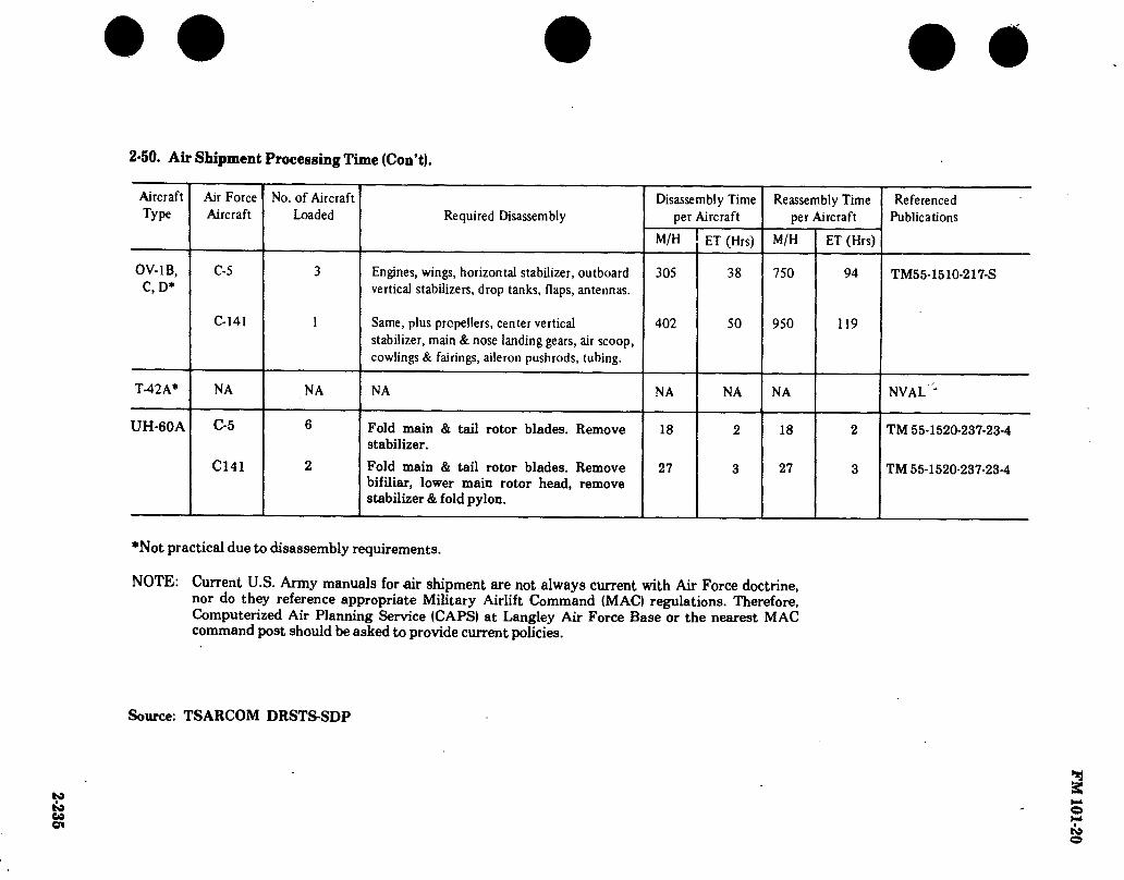
2-235
2-50. Air Shipment Processing Time (Con’t).
Aircraft Type
Air Force Aircraft
No. of Aircraft Loaded Required Disassembly
Disassembly Time per Aircraft
M/H ET (Hrs)
Reassembly Time per Aircraft
M/H ET (Hrs)
Referenced Publications
OV-1B, C, D*
C-5
C-141
Engines, wings, horizontal stabilizer, outboard vertical stabilizers, drop tanks, flaps, antennas.
Same, plus propellers, center vertical stabilizer, main & nose landing gears, air scoop, cowlings & fairings, aileron pushrods, tubing.
305
402
38
50
750
950
94
119
TM55-1510-217-S
T-42A* NA NA NA NA NA NA NVAL '
UH-60A C-5
C141
Fold main & tail rotor blades. Remove stabilizer.
Fold main & tail rotor blades. Remove bifiliar, lower main rotor head, remove stabilizer & fold pylon.
18
27
18
27
TM 55-1520-237-23-4
TM 55-1520-237-23-4
*Not practical due to disassembly requirements.
NOTE: Current U.S. Army manuals for air shipment are not always current with Air Force doctrine, nor do they reference appropriate Military Airlift Command (MAC) regulations. Therefore, Computerized Air Planning Service (CAPS) at Langley Air Force Base or the nearest MAC command post should be asked to provide current policies.
Source: TSARCOM DRSTS-SDP
FM
101-20

FM 101-20
2-51. Weight and Cube for Crated Shipment.
AH-64A CH-47A CH-47B CH-47C CH-47D CH-54A CH-54B OH-6A
TH-55A U-8F
U-21/RU-21 OV-1B OV-1C OV-1D T-41B T-42A UH-60A
(*) Crating of aircraft not recommended.
SOURCE: TSARCOM-DRSTS-SDP
TYPE OF AIRCRAFT WEIGHT (LB) CUBE
(CU FT)
AH-1G AH-1S
10,000 10,000
2800 2800
OH-58A UH-1B UH-1H UH-1M
5,000 10,409 13,937 10,610
1,280 2.241 3,213 2.241
U-10A NVAL NVAL
+ 2-236
V
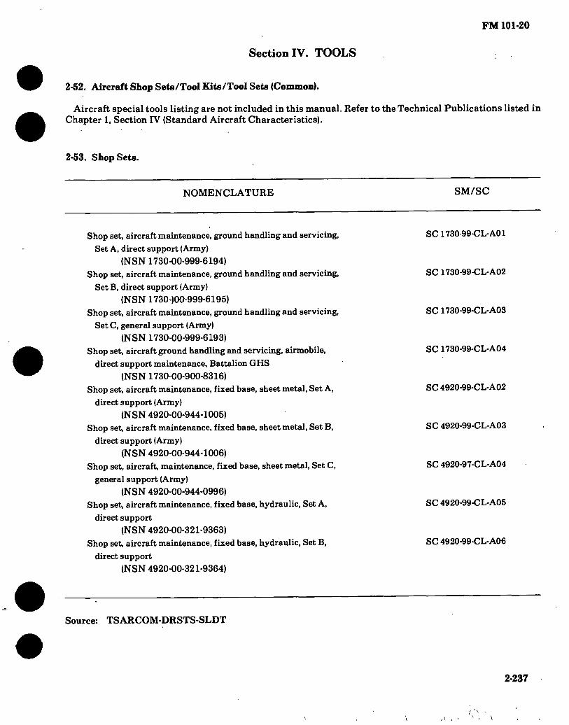
FM 101-20
Section IV. TOOLS
2-52. Aircraft Shop Sets/Tool Kits/Tool Sets (Common).
Aircraft special tools listing are not included in this manual. Refer to the Technical Publications listed in Chapter 1, Section IV (Standard Aircraft Characteristics).
2-53. Shop Sets.
NOMENCLATURE SM/SC
Shop set, aircraft maintenance, ground handling and servicing, Set A, direct support (Army)
(NSN 1730-00-999-6194) Shop set, aircraft maintenance, ground handling and servicing,
Set B, direct support (Army) (NSN 1730-)00-999-6195)
Shop set, aircraft maintenance, ground handling and servicing, Set C, general support (Army)
(NSN 1730-00-999-6193) Shop set, aircraft ground handling and servicing, airmobile,
direct support maintenance. Battalion GHS (NSN 1730-00-900-8316)
Shop set, aircraft maintenance, fixed base, sheet metal, Set A, direct support (Army)
(NSN 4920-00-944-1005) Shop set, aircraft maintenance, fixed base, sheet metal, Set B,
direct support (Army) (NSN 4920-00-944-1006)
Shop set, aircraft, maintenance, fixed base, sheet metal, Set C, general support (Army)
(NSN 4920-00-944-0996) Shop set, aircraft maintenance, fixed base, hydraulic, Set A,
direct support (NSN 4920-00-321-9363)
Shop set, aircraft maintenance, fixed base, hydraulic, Set B, direct support
(NSN 4920-00-321-9364)
SC 1730-99-CL-A01
SC 1730-99-CL-A02
SC 1730-99-CL-A03
SC 1730-99-CL-A04
SC4920-99-CL-A02
SC 4920-99-CL-A03
SC 4920-97-CL-A04
SC 4920-99-CL-A05
SC 4920-99-CL-A06
Source: TSARCOM-DRSTS-SLDT
2-237
\

FM 101*20
2*53. Shop Sets (Con’t).
NOMENCLATURE SM/SC
Shop set, aircraft maintenance, fixed base, hydraulic, Set C, general support
(NSN 4920-00-321-9373) Shop set, aircraft maintenance, fixed base, welding, Set A, direct support
(NSN 4920-00-321-9375) Shop set, aircraft maintenance, fixed base, welding, Set B, direct support
(NSN 4920-00-321-9376) Shop set, aircraft maintenance, fixed base, welding, Set C, general support
(Army)
(NSN 4920-00-944-0785) Shop set, aircraft maintenance, fixed base, tool crib, Set A, direct support
(NSN 4920-00-321-9397) Shop set, aircraft maintenance, fixed base, tool crib. Set B, direct support
(NSN 4920-00-321-9403) Shop set, aircraft maintenance, fixed base, tool crib. Set C, general support
(NSN 4920-00-321-9405) Shop set, aircraft maintenance, fixed base, electrical, Set A, direct support
(Army)
(NSN 4920-00-944-0761) Shop set, aircraft maintenance, fixed base, electrical, Set B, direct support
(Army)
(NSN 4920-00-944-0760) Shop set, aircraft maintenance, fixed base, electrical. Set C, general support
(Army)
(NSN 4920-00-944-0757) Shop set, aircraft maintenance, fixed base, flaw detection, Set B, direct
support
(NSN 4920-00-321-9410) Shop set, aircraft maintenance, fixed base, flaw detection. Set C, general
support
(NSN 4920-00-321-9411) Shop set, aircraft maintenance, fixed base, paint, Set B, direct support
(Army)
(NSN 4920-00-944-0759) Shop set, aircraft maintenance, fixed base, paint, Set C, general support
(Army)
(NSN 4920-00-944-1007) Shop set, aircraft maintenance, fixed base, instrument, Set B, direct support
(NSN 4920-00-321-9416)
SC 4920-99-CL-A07
SC 4920-99-CL-A08
SC 4920-99-CL-A09
SC 4920-99-CL-A10
SC 4920-99-CL-A11
SC 4920-99-CL-A12
SC 4920-99-CL-A13
SC 4920-99-CL-A14
SC 4920-99-CL-A15
SC 4920-99-CL-A16
SC 4920-99-CL-A17
SC 4920-99-CL-A18
SC 4920-99-CL-A19
SC 4920-99-CL-A20
SC 4920-99-CL-A21
A
2*238

FM 101*20
2-53. Shop Sets (Con’t).
NOMENCLATURE SM/SC
Shop set. aircraft maintenance, fixed base, instrument. Set C. general
support (Army)
(NSN 4920-00-944-0784) Shop set, aircraft maintenance, fixed base, engine, Set B, direct support
(Army)
(NSN 4920-00-944-0884)
Shop set, aircraft maintenance, fixed base, engine. Set C, general support
(Army)
(NSN 4920-00-944-0786) Shop set, aircraft maintenance, fixed base, propeller and rotor. Set B, direct
support (Army)
(NSN 4920-00-944-1014) Shop set, aircraft maintenance, fixed base, propeller and rotor. Set C, general
support (Army)
(NSN 4920-00-944-1015) Shop set, aircraft maintenance, fixed base, power train, general support
(Army)
(NSN 4920-00-944-0838)
Shop set, aircraft maintenance, semitrailer mounted, A-l, tool crib, electrical,
flaw detection, direct support
(NSN 4920-00-621-2032) Shop set, aircraft maintenance, semitrailer mounted, A-2, sheet metal, welding,
hydraulic, direct support
(NSN 4920-00-621-2033)
Shop set, aircraft maintenance, semitrailer mounted, B-l, tool crib and flaw
detection, direct support
(NSN 4920-00-621-2034) Shop set, aircraft maintenance, semitrailer and trailer mounted, B-2, electrical,
instrument, and hydraulic, direct support
(NSN 4920-00-621-2035) Shop set, aircraft maintenance, semitrailer mounted, B-3, sheet metal and
welding, direct support
(NSN 4920-00-621-2036) Shop set, aircraft maintenance, semitrailer mounted, B-4, machine and
engine shop, direct support
(NSN 4920-00-621-2037)
• “ —:
SC 4920-99-CL-A22
SC 492Ó-99-CL-A23
SC 4920-99-CL-A24
SC 4920-99-CL-A25
SC 4920-99-CL-À26
SC 4920-99-CL-A27
SC 4920-99-CL-A28
SC 4920-99-C L-A29
SC 4920-99-CL-A30
SC 492U-99-ÍL-A31
SC 4920-99-CL-A32
SC 4920-99-CL-A33
2-239

FM 101-20
2-53. Shop Sets (Con’t).
NOMENCLATURE SM/SC
Shop set, aircraft maintenance, trailer mounted, B-6, paint shop, SC 4920-99-CL-A34
direct support
(NSN 4920-00-621-2038)
Shop set, aircraft maintenance, semitrailer mounted, C-l, tool crib, SC 4920-99-CL-A35
general support
(NSN 4920-00-621-2039)
Shop set. aircraft maintenance, semitrailer and trailer mounted, C-2, SC 4920-99-CL-A36
electrical shop, general support
(NSN 4920-00-621-2040)
Shop set, aircraft maintenance, semitrailer mounted, C-3, flaw detection, SC 4920-99-CL-A37
general support
(NSN 4920-00-621-2041)
Shop set, aircraft maintenance, semitrailer mounted, C-4, sheet metal, SC 4920-99-CL-A38
general support
(NSN 4920-00-621-2042) Shop set, aircraft maintenance, semitrailer mounted, C-5, welding, general SC 4920-99-CL-A39
support
(NSN 4920-00-621-2043)
Shop set, aircraft maintenance, semitrailer mounted, C-6, machine shop, SC 4920-99-CL-A40
general support
(NSN 4920-00-621-2044)
Shop set, aircraft maintenance, semitrailer mounted, C-7, engine and hydraulic, SC 4920-97-CL-A41
general support
(NSN 4920-00-621-2045)
Shop set, aircraft maintenance, semitrailer mounted, C-8, instrument shop, SC 4920-99-CL-A42
general support
(NSN 4920-00-621-2046) Shop set, aircraft maintenance, trailer mounted, C-10, paint shop, general SC 4920-99-CL-A43
support
(NSN 4920-00-649-7098) Shop set, aircraft maintenance, semitrailer mounted, B-5, propeller and rotor, SC 4920-97-CL-A44
direct support
(NSN 4920-00-649-6509) Shop set, aircraft maintenance, semitrailer mounted, C-9, propeller and SC 4920-99-CL-A45
rotor, general support
(NSN 4920-00-649-6509)
Shop set, aircraft maintenance, semitrailer mounted, C-l 1, power train, SC 4920-99-CL-A46
general support
(NSN 4920-00-649-6510)

FM 101-20
2-53. Shop Sets (Con’t).
NOMENCLATURE SM/SC
Shop set, aircraft maintenance, airmobUe, direct support section, airmobile
division
(NSN 4920-00-906-9727)
Shop set, aircraft maintenance, airmobile, tool crib, direct support maintenance,
Battalion set No. 1
(NSN 4920-00-906-9728)
Shop set, aircraft maintenance, airmobile, electrical, instrument,
hydraulic, direct support maintenance, Battalion set No. 2
(NSN 4920-00-906-9729) Shop set, aircraft maintenance, airmobile, sheet metal and welding,
direct support, Battalion set No. 3
(NSN 4920-00-906-9730)
Shop set, aircraft maintenance, airmobile, machine and engine,
direct support maintenance, Battalion set No. 4
(NSN 4920-00-906-9731)
Shop set, aircraft maintenance, airmobile, propeller and rotor, direct
support maintenance, Battalion set No. S
(NSN 4920-00-906-9732) Shop set, aircraft maintenance, airmobile, flaw detection, direct
support maintenance, Battalion set No. 6
(NSN 4920-00-906-9733)
Shop set, aircraft maintenance, airmobile, company size, direct
support, CH-47
(NSN 4920-00-133-8157) Shop set aircraft maintenance, airmobile, company size, direct
support, CH-47/OH-6
(NSN 4920-00-133-8156)
Shop set, aircraft maintenance, airmobile, company size, direct
support, UH-1
(NSN 4920-00-133-8154) Shop set, aircraft maintenance, airmobile, company size, direct
support, UH-l/OH-6
(NSN 4920-00-133-8158)
SC 4920-99-CL-A47
SC 4920-99-CL-A48
SC 4920-99-CL-A49
SC 4920-99-CL-A50
SC 4920-99-CL-A51
SC 4920-99-CL-A52
SC 4920-99-CL-A53
SC 4?20-99-CL-A89
SC 4920-99-C L-A89.
SC 4920-99-CL-A89
SC 4920-99-CL-A89
2-241

FM 101-20
2-53. Shop Sets (Con’t).
NOMENCLATURE SM/SC
Shop Set, Aviation Intermediate Maintenance: electrical, instrument, airmobile (NSN 4920-00-165-1453)
Shop Set, Aviation Intermediate Maintenance: hydraulic, airmobile (NSN 4920-00-165-1454)
Shop Set, Aviation Intermediate Maintenance: machine shop, airmobile (NSN 4920-00-405-9279)
Shop Set, Aviation Intermediate Maintenance: power train, airmobile (NSN 4920-00-001-4132)
Shop Set, Aviation Intermediate Maintenance: rotor, airmobile (NSN 4920-00-405-9270)
Shop Set, Aviation Intermediate Maintenance: sheet metal, airmobile (NSN 4920-00-166-5505)
Shop Set, Aviation Intermediate Maintenance: tool crib, airmobile (NSN 4920-00-472-4183)
Shop Set, Aviation Intermediate Maintenance: turbine engine, airmobile (NSN 4920-00-224-3684)
Shop Set, Aviation Intermediate Maintenance: welding, airmobile (NSN 4920-00-163-5093)
SC 4920-99-CL-A91
SC 4920-99-CL-A91
SC 4920-99-CL-A91
SC 4920-99-CL-A91
SC 4920-99-CL-A91
SC 4920-99-CL-A91
SC 4920-99-CL-A91
SC 4920-99-CL-A91
SC 4920-99-CL-A91
2-242

FM 101-20
2-54. Tool Kits.
NOMENCLATURE SM/SC
Tool kit, aircraft mechanic’s, general
(NSN 5180-00-323-4692) Tool kit, airframe repairer: Army aircraft
(NSN 5180-00-323-4876) Tool kit, hydraulic repairer, Army aircraft
(NSN 5180-00-323-4891)
SC 5180-97-CL-A01
SC 5180-99-CL-A02
SC 5180-97-CL-A03
Tool kit, instrument repairer, Army aircraft
(NSN 5180-00-323-4913) Tool kit, electrical repairer, Army aircraft
(NSN 5180-00-323-4915)
Tool kit, power plant: Army aircraft (NSN 5180-00-323-4944)
Tool kit, aircraft inspection, technical
(NSN 5180-00-323-5114) Tool kit, trainer, flight simulator, set No. 1
(NSN 5180-00-859-0556) Tool kit, Army aircraft, crash investigation
(NSÑ 5180-00-903-1049)
Tool kit, powertrain: Army aircraft (NSN 5180-00-003-5267)
SC 5180-99-CL-A05
SC 5180-99-CL-A06
SC 5180-99-CL-A07
SC 5180-97-CL-A09
SC 5180-97-CL-A10
SC 5180-99-CL-A11
SCi5180-99-CL-A13
2-55. Tool Sets.
NOMENCLATURE
Tool Set, Aviation Unit Maintenance. Set No. 1 : Airmobile
(NSN 4920-00-159-8727)
Tool Set, Aviation Unit Maintenance. Set No. 1 : Fixed Base (NSN 4920-00-504-9258)
SM/SC
SC 4920-99-CL-A90
SC 4920-99-CL-A90
Tool Set, Aviation Unit Maintenance. Reciprocating Engine Supplement (NSN 4920-00-159-8728)
Tool Set, Aviation Unit Maintenance: company size. Set No. 2, airmobile (NSN 4920-00-567-0476)
SC 4920-99-CL-A90
SC 4920-99-CL-A92
2-243

FM 101-20
Section V. INSPECTIONS
2-56. Aircraft Inspections.
Aircraft Phased Maintenance (PM), Special (SP) Inspection Criteria, Time Between Overhaul (TBO) and Retirement Life Schedules are not included in this manual. Refer to the technical publication listed.
AIRCRAFT TECHNICAL PUBLICATIONS
INSPECTION
PM TBO RET SP
UH-1H UH-1H/V, EH-1H/X
AH-1G, TH-1G AH-1G, TH-1G AH-1S (ALL) AH-IS(MOD) AH-1S (PROD/ECAS) AH-1S (MODERNIZED)
CH-47B/C CH-47A CH-47B/C CH-47D CH-47D CH-47D CH-47D CH-54A CH-54B
OH-6A
AH-64A AH-64A
TM 55-1520-210-PM TM 55-1520-210-23
TM 55-1520-221-PM TM 55-1520-221-23 TM 55-1500-220-PM TM 55-1520-234-23 TM 55-1520-236-23 TM 55-1520-239-23
TM 55-1520-227-PM TM 55-1520-209-23 TM 55-1520-227-23 TM 55-1520-240-PM TM 55-1520-240-23 TM 55-1520-240-PMS TM 55-1520-240-23-1 thru -10 TM 55-1520-217-23/1 TM 55-1520-217-23/2
TM 55-1520-214-23
TM 55-1520-238-23(DRAFT) TM 55-1520-238-PM(DRAFT)
X
X
X X
X X X
X X
X X
X
X
X X X
X X
X X
X
X
X X X
X X
X X
X
X
2-244

FM 101-20
2-56. Aircraft Inspections (Con’t).
AIRCRAFT
OH-58A/C OH-58A/C
UH-IB
UH-1M UH-1M
UH-60A
OV-1B/C OV/RV-1 SERIES
OV/RV-1D
U-8F
U-21A, RU-21A/D U-21/RU-21
RU-21B/C
RU-21H
TECHNICAL PUBLICATIONS
TW 55-1520- TW 55-1520-
-228-23 -228-PM
TÍA 55-1520-219-20
TW 55-1520- 'IW 55-1520-
-220-23 -220-PM
TW 55-1520-237-23
TW 55-1510- TW 55-1510-
TW 55-1510-
TW 55-1510-
TW 55-1510- TW 55-1510-
TW 55-1510-
TW 55-1510-
-204-23 -217-PM
-213-23
-201-20
-209-23 -200-PM
-214-23
-215-23
INSPECTION PM TBO RET SP
X
X
X
X
X
X
X
X
X
X
X
X
X
X
X
X
X
X
X
X
X
X
X
X
X
X
X
Source: TSARCOM-DRSTS-MEM
2-245

FM 101-20
Section VI. FUEL AND OIL
2-57. Fuel and Oil Costs (FY 78).
TYPE AIRCRAFT
AH-1G/S CH-47A CH-47B CH-47C/D .... CH-54A CH-54B OH-6A OH-58A/C .... UH-1B UH-1H/M/V .. EH-1H/EH-1X TH-55A U-8F U-10A U-21A RU-21A RU-21B RU-21C
RU-21D U-21G RU-21E U-21F RU-21J RU-21H OV-1B OV-lC(w/L-15). OV-1D T-41B T-42A C-12A UV-18A UH-60A AH-64A
FUEL
GRADEi/
JP-4/5 JP-4 JP-4/5 JP-4/5 JP-4/5 JP-4/5 JP-4 JP-4 JP-4/5 JP-4
115/145 115/145 115/145 JP-4/5 JP-4/5 JP-4/5 JP-4/5
JP-4/5 JP-4/5 JP-4/5 JP-4/5 JP-4/5 JP-4/5 JP-4/5 JP-4/5 JP-4/5 115/145 115/145 JP-4/5 JP-4/5 JP-4/5 JP-4/5
COST PER
GAL 2/
1.17/1.26 1.17
1.17/1.26 1.17/1.26 1.17/1.26 1.17/1.26
1.17 1.17
1.17/1.26 1.17
1.51 1.51 1.51
1.17/1.26 1.17/1.26 1.17/1.26 1.17/1.26
1.17/1.26 1.17/1.26 1.17/1.26 1.17/1.26 1.17/1.26 1.17/1.26 1.17/1.26 1.17/1.26 1.17/1.26
1.51 1.51
1.17/1.26 1.17/1.26 1.17/1.26 1.17/1.26
OIL
MIL-L- SPECIFI-
CATION 1/
7808/23699 23699 23699 23699 23699 23699 23699 23699 23699 23699
22851 22851 22851 23699 23699 23699 23699
23699 23699 23699 23699 23699 23699 23699 23699 23699 22851 22851 23699 23699 23699 23699
COST PER QT3/
2.99 2.99 2.99 2.99 2.99 2.99 2.99 2.99 2.99 2.99
1.10 1.10 1.10 2.99 2.99 2.99 2.99 2.99 2.99 2.99 2.99 2.99 2.99 2.99 2.99 2.99 1.10 1.10 2.99 2.99 2.99 2.99
2-246

FM 101-20
2-57. Fuel and OU Costs (FY 78) (Con’t).
DATA SOURCE : \] TB 55-9150-200-25, Engine and Transmission Oils, Fuels and Additives for Army Aircraft.
2/ DFSC Price Bulletin No. 80-1 Standard Prices of Bulk Petroleum Items.
Zj Federal Supply Catalog, C-ML-A, Army Management Data List, and Defense General Supply Center.
Note: The above costs are subject to frequent change and should be used for planning only.
SOURCE: GMPA-STSGP-FM AV 977-6752/6758
2-247

2-248 2-58. Fuel and Oil Consumption,
TYPK
OF
AIRCRAFT
NUMBER
OF
ENGINES
ENGINE
MODEL
DESIGN
POWER PER ENGINE (SHP)
MAXIMUM NORMAL CRUISE1
DRIVE
ÍRAIN
LIMIT SHP
FUEL CONSUMPTION
GAL PER AIRCRAFT HR
MAXIMUM NORMAL CRUISE
OIL
CONSUMPTION
QTSPER
AIRCRAFT HR
AH-1S AH-1G CH-47A
CH-47B
CH-47C
CH-47D
CH-54A
CH-54B
OH-6A
OH-58A/C UH-1B
UH-1H/M/V EH-1H/EH-1X U-21A
RU-21A
RU-2IB
RU-2IC
RU-21D
U-21G
RU-21H U-21F
OV-1B
CV-1C
OV-1D
T53-L-703 T53-H3B
T55-L-7
T55-L-7C
T55-L-I IA
T55-L-712 T73-P-I
T73-P-700
T63-A-5A/70C
T63-700
T53-L-1 ID
T53-L-I3B
T74-CP-700
T74-CP-700
T74-CP-702
T74-CP-702
T74-CP-700
T74-CP-700
T74-CP-700
PT6A-28
T53-L-7
T53-L-15
T53-L-701
1485 1400
2650
2850
3750
4500
4500
4800
317
317
1100
1400
550
550
750
750
550
550
550
680
1100
1150
1400
1300 1250
2200 2400
3000
3750 4000
4430
270
270
900
1250
495
495
688 688 495
495
495
620
900
1000
1250
1125 937.5
1650.0
1800.0
2250.0
2813.0
3000.0
3322.5
202.5
202.5
675.0
937.5
371.3
371.3
516.0
516.0
371.3
371.3
371.3
465.0
675.0
750.0
937.5
1290 ü/ 1100
5200
'5200
6000
7500
5400
6600
250
317
1100
1100
620
620
109.2 á/ 101.5® 482.0
478.8
497.1
625.0
656.7
716.4
29.0
33.7
114.5
106.0
115.4
115.4
117.1
117.1
115.4
115.4
115.4
128.1
225.0
219.6
252.2
109.24) 101.551
407.8
442.0
497.1
507.0
-656.7
716.4
29.0
29.1
96.5
106.0
107.0
107.0
117.1
117.1
107.0
107.0
107.0
117.1
190.1
198.5
232.8
100.84) ■“93.1
305.9
331.5
372.8
380.8
555.2^
597.12/
17.6
23.6
78.5
93.1
80.2
80.2 97.5
97.5
80.2
80.2
80.2
89.1
139.2
148.5
174.6
0.56 0.56
1.60
1.60
1.60
1.60
1.04
1.04
0.20 0.20 0.56
0.56
0.20 0.20 0.20 0.20 0.20 0.20
0.20 0.20
1.12
1.12
1.12
\J Cruise - 75% Normal 2/ Based on 75%
5/ Hog Mission Drive Train Limit
2.000 Ft. Pressure Altitude 9.000 Lbs. Gross Weight
3/ 30 Min. 4/ Eight Tow Missiles
2.000 Ft. Pressure Altitude
9.000 Lbs. Gross Weight
• • • • • F
M 101-20

2*249
• • • • • 2-58. Fuel and Oil Consumption (Con’t).
TYPE OF
AIRCRAFT
NUMBER OF
ENGINES
ENGINE
MODEL
DESIGN POWER PER ENGINE (BHP)
MAXIMUM NORMAL CRUISE 1
FUEL CONSUMPTION GAL PER AIRCRAFT HR
MAXIMUM NORMAL CRUISE
OIL CONSUMPTION QTSPER AIRCRAFT HR
AH-64 A TH-55 U-8F U-10A T-41B T-42A C-12A UV-18A UH-60A
T700-GE701 H10-360- B1A 0-480-3A GO-480-G1D6 IO-360-D IO-470-L PT-6-38
T700-GE700
3/ 1694 180 340 340 210 260
2/ 750
4/1414 160 320 320 210 260
5/ 1414 120.0 240.0 240.0 157.5 195.0
15.1 60.5 30.2 15.5 39.2
115.4
4/1546 .5/ 1311
6/136.5 13.4 56.8 28.4 15.5 39.2
107.0
22.4
10.1 42.6 20.1 11.6 29.4 80.2
156
0.34 0.17 0.50 0.25 0.25 0.50 0.20
0.33
J/ Cruise = 75% Normal
2J Shaft Horsepower
J/ Contingency (single engine condition only — 1723)
4/ Intermediate Rated Power (Transmission Limits)
_5/ Max. Continuous
6/ Primary Mission Fuel Consumption
Source: DARCOM PM’S TSARCOM RPO’S and PM’S F
M101-2
0

FM 101-20
Section VII. MAINTENANCE MAN-HOURS
2-59. Total Direct Productive Man-Hours Per Flight Hour.
TYPE AIRCRAFT
AVIATION UNIT MAINTENANCE (AVUM) 1/
AVIATION INTERMEDIATE MAINTENANCE (AVIM)^/ TOTAL
AH-64 3/ AH-1G AH-lS(series) CH-47A/B CH-47C CH-47D CH-54 OH-6A OH-58A OH-58C UH-1B/C/D
/M/V EH-1X UH/EH-1H UH/EH-60A T-41B OV-1B/C/D RV-1D U-21/RU-21
2.94 3.50 7.99 9.20
10.83 16.21 2.84 2.12 1.98 2.85
2.85 2.85 1.91 2.93 4.22 4.22 4.02
1.0 1.11 3.80 4.30 4.27 3.89 1.01 .60 .55
1.06
1.06 1.06 .54
1.78 1.23 1.23 1.11
3.94 4.61
11.79 13.50 15.10 20.10
3.85 2.72 2.53 3.91
3.91 3.91 2.45 4.71 5.45 5.45 5.13
U AVUM is that organizational and integrated Direct Support Maintenance performed in company sized aviation units (10 or more aircraft).
u u
AVIM is the amalgamation of direct and general support aviation maintenance units into a single maintenance unit performing both direct and general support aircraft maintenance.
Direct productive maintenance manhour per flight hour are currently being developed for the TOE MACRIT and are not yet available.
NOTE: The above factors are direct productive man-hours only and are based on TOE Manpower Authorization Criteria (MACRIT). To include indirect productive man- hours multiply Dir Maintenance Man-Hours by 1.40.
REFERENCE: AR 570-2 /change TSARCOM-DRSTS-MPSD
2-250

FM 101-20
2-60. Direct Productive Maintenance Man-Hours \J Per Flight Hour for Technical Inspectors.
TYPE AIRCRAFT
AH-64 2/ AH-1G AH-lS(Series) CH-47A/B CH-47C CH-47D CH-54A/B OH-6A OH-58A OH-58C UH-1B/C/ D
/M/V EH-1X UH/,EH-1H UH/EH-eOA1
0V-1B/C7b RV-1D U-21/RU-21 T-41B
MOS
66R 66Y 66Y 66U 66U 66U 66X 66V 66V 66V 66N
66N 66N 66T 66H 66H 66G
AVIATION UNIT MAINTENANCE (AVUM)
.26
.21
.39
.64 1.5 2.20
.35
.13
.12
.28
.28
.28
.21
.25
.25
.37
AVIATION INTERMEDIATE MAINTENANCE (AVIM)
.12
.12
.19
.19 0.30
.38
.08
.05
.05
.15
.15
.15
.03
.14
.14
.06
1/ To include indirect productive man-hours multiply direct maintenance man-hours by 1.40.
2/ Man-hour factor not available.
2-251

FM 101-20
2-61. Manpower Authorization Criteria (MACRIT).
AIRCRAFT MAINTENANCE AND
TECHNICAL INSPECTION OPERATIONS
(MOS 67/66 SERIES)
AIRCRAFT MAINTENANCE AND
TECHNICAL INSPECTION OPERATION IMOS 67/68 SERIES)
1. Productive man-Hours. Ref AR570-2
2. Authorization formula and criteria.
a. Aviation Unit Maintenance IAVUM).
Ill Density of Aircraft MACRIT Factor Number Positions by Type X by MOS = Authorized
II to 9 Aircraft Category 1) USE TABLE I ONLY - MOS 67 Series
121 Density of Aircraft MACRIT Factor Number Positions by Type x by MOS = Authorized
110 or more aircraft Category I) USE TABLES I AND la - MOS 67/68 Series
(31 Density of Aircraft MACRIT Factor Number Positions by Type x by MOS = Authorized
II to 9 Aircraft Category II) USE TABLE II ONLY - MOS 67 Series
141 Density of Aircraft MACRIT Factor Number Positions by Type X by MOS = Authorzied
110 or more Aircraft Category III USE TABLES II AND I la - MOS 67/68 Series
b. Aviation Intermediate Maintenance (AVIMI.
Density of Aircraft MACRIT Factor Number Positions by Type x by MOS = Authorized
(Table III Category III (MOS67 and 68 Series)
3. For force developers who utilize Annual Available Productive Man-hour (AAPMH) other than those listed in paragraph 2-7b(3). AR670-2 and/or Flying Hours as listed in Table IV. Column A below, substitute appropriate AAPMH and/or Flying Hours requirements in the following authorization formulae and criteria.
a. Aircraft Repairer (with FLYING CREWCHIEFI (MOS 67 Series).
STEP1: Maintenance man-hours/ flight hour (Table V)
Annual flying hours (Table IV) or other source 2
.50 Annual Available 1 productive man-hours by category or other source 3
STEP 2: Density of Aircraft by Type
MACRIT Factor (From Step 1 above)
Number Positions plus Number Positions plus one Crewchief per Aircraft
Annual Available productive man-hours by category MACRIT or other m Factor source 3 by MOS
2-252

FM 101-20
b. AVUM: Aircraft Repairer without crewchiefs (MOS 67 Series).'*
Density of Aircraft by Type
Maintenance man-hours/ X flight hour (Table V)
Annual flying hours (Table IV) or other source2
c. AVUM: Aircraft Component Repairer (MOS 68 Series).
Density4 of Aircraft X by type
Maintenance man-hours/ X flight hour (Table VI)
Annual flying hours (Table IV| or other source2
Annual Available productive man-hours by category or other source3
Annual Available productive man-hours by category or other source3
Number Positions Authorized
Number Positions Authorized
d. AVIM: Aircraft & Aircraft Component Repair (MOS 67 &68 Series).
Density Maintenance Annual flying of Aircraft X man-hours/ X hours (Table iy) by type flight hour or other source2
(Table VI)
Annual Available productive man-hours by category or other source3
Number Positions Authorized
e. TECHNICAL INSPECTORS: (MOS 67 Series only).
Density of Aircraft X by type
Maintenance man-hours/ X flight hour (Table VII)
Annual flying hours (Table IV) or other source2
Annual Available productive man-hours by category or other source3
Number Positions Authorized
NOTE 1: NOTE 2: NOTE 3: NOTE 4: NOTE 5:
Flying crewchiefs are 36 percent productive directive/non-flying crewchiefs are 50 percent projective direct Use the flying hours listed in Table IV (Column B) or those documented flight hours necessary to accomplish the mission. Substitutions may be made when the AAPMH figures vary from those listed in paragraph 2-7b(3), AR570-2 Only those units with 10 or more aircraft will be authorized MOS 68 Series. Aircraft OV-1B/C/D, U-21A, OH-6A, OH-58A, and AH-1G/S are not authorized flying crew chief. Nonflying crew chief's positions may be designated from within the authorized position computation.
SAMPLE COMPUTATIONS (For units flying hours and/or AAPMH other than those in this regulation, see paragraph 3above).
1. AVUM: Aircraft Repairer (with FLYING CREWCHIEF) (MOS 67 Series).
ASSUME 13 UH-1H, annual flying hours = 100; and 2300 AAPMH.
STEP 1: Maintenance man-hours/ flight hour (Table V)
4.12
X
X
Annual flying hours (Table IV) or other source^
1000
.50 Annual Available productive man-hours by catMory or other sourceä
1150
Annual Available productive man-hours by category or other = M ACRIT source3 FACTOR
~ 2300 = 1.29
STEP 2: Density of Aircraft by Type
13
X
X
MACRIT Factor Number OneCrewchief by MOS = Positions _j_ per Aircraft =
1.29 = 16.77 13
Total (67N) Positions Authorized
= 29.97 or30
2. AVUM: Aircraft Repairer (without crewchief) (MOS 67 Series).
ASSUME 17 AH-1S. annual flying hours = 500 and 2600 AAPMH.
Density of Aircraft by type
17
X
X
Maintenance man-hours/ flight hour (Table V)
4.93
Annual flying hours (Table IV) or other source2
500
Annual Available productive man-hours by category or other source3
2600
Number (67Y) Positions Authorized
16.11 or 16
TATION^aST"6"1 ReP‘,Írer Computation for AV1M and AVUM 'with 10 or more aircraft) are the same as SAMPLE COMPU-
2-253

FM 101-20
MACfUT FACTORS
AVIATION UNIT MAINTENANCE lAVUMt
TABLE I iMOSdT SERIES) Ctltfory I Umt(8600 AAPMHi
UN A30a8l A30871 A 30 >96
K31T494
K31M4 KSnift1 K3Q3T61 K303631 K30449< K3064S K31048 K30MS1
K30M6 K89660 K89694
OV IC/D U-aiA UH IB'M UH lH ÇH-47A CH 47B CH-4TC OH-6A OH-&6A CH>64A/BAH IG'S
116 1 78
806
4-78
AIRCRAFT OV IB
AIRPLANE REPAIRER <67GI 1 76
UTILITY HELICOPTER REPAIRER (67NI
MEDIUM CARGO HELICOPTER REPAIRER (67U)
OBSERVATION HELICOPTER REPAIRER 167V)
HEAVY CARGO HELICOPTER REPAIRER 167X1 .
ATTACK HELICOPTER REPAIRER 167Y)
AIRPLANE INSPECTOR (Ö7G) 81 >1
UTILITY HELICOPTER INSPECTOR167NI
MEDIUM CARGO HELICOPTER INSPECTOR (67UI
OBSERVATION HELICOPTER INSPECTOR 167V)
HEAVY CARGO HELICOPTER INSPECTOR 167X)
ATTACK HELICOPTER INSPECTOR 167YI
NOTE I; INCLUDESONE FLYING CREWCHIEF PER AIRCRAFT NOTE 9, IN UNITS WITH 10 OR MORE AIRCRAFT, FOR POSITIONS NOT JUSTIFIED BY MACRIT BUT ESSENTIAL FOR THE OPERATION OF THE UNIT, A TRADE-
OFF IS AUTHORISED AS LONG AS TOTAL AUTHORISATION FOR POSITIONS IS NOT EXCEEDED.
.80
AIRCRAFT POWERPLANT REPAIRER (MB) ,06
AIRCRAFT POWERTRAIN REPAIRERIUD) .08
AIRCRAFT ELECTRICIAN (UP) .04
AIRCRAFT STRUCTURAL REPAIRER (6801 18
AIRCRAFT PNEUDRAULfCS REPAIRER <66H) .08
TABLE UlMOS 68 SERIES) Cntfory I Unit <8600 AAPMHI
.04 .08 .06 .07
.08 .08
.08 .04
.18 .18
.04 .08
.06 .06
.01 .08
.06 .07
.01 .08 .06 .04.
.11 .06
.37 .06
.11 .03
.16 .09
.06 NONE
.03 .09
.04 .10
.01 .09
.16 .06
.0) .06
.07
.07
.08
.06
.08
LIN
AIRCRAFT OV-1B
AIRPLANE REPAIRER(67G| 162
UTILITY HELICOPTER REPAIRER (67N|
MEDIUM CARGO HELICOPTER REPAIRER (67U)
OBSERVATION HELICOPTER REPAIRER (67V|
HEAVY CARGO HELICOPTER REPAIRER (67X) ..
ATTACK HELICOPTER REPAIRER (67Y)
AIRPLANE INSPECTOR (67G) 19
UTILITY HELICOPTER INSPECTOR <67N|
MEDIUM CARGO HELICOPTER INSPECTOR (67U)
OBSERVATION HELICOPTER INSPECTOR (67V)
HEAVY CARGO HELICOPTER INSPECTOR (67X)
ATTACK HELICOPTER INSPECTOR (67Y) . . .
MACRIT FACTORS2
AVIATION UNIT MAINTENANCE (AVUM)
TABLE 11 (MOS 67 SERIES)
Cctagory II Unit (2700 AAPMH)
A30221 A30271 A30946 K317491 K3./961 K303781 K303831 K304491 K30646 K31042 K305161 K29660 A30296 K31604 K30616 K 29694
OV IC/D U-21A UH-1BM UH-lH CH 47A CH-47B CH-47C OH-6A OH 68A CH-64A/B AH-1G/S
1 71 1.66
NOTE 1. INCLUDESONE FLYING CREWCHIEF PER AIRCRAFT. NOTT 2 IN UNITS WITH 10 OR MORE AIRCRAFT. FOR POSITIONS NOT JUSTIFIED BY MACRIT BUT ESSENTIAL FOR THE OPERATION OF THE UNIT A TRADE-
OFF IS AUTHORIZED AS LONG AS TOTAL AUTHORIZATION FOR POSITIONS IS NOT EXCEEDED
AIRCRAFT POWERPLANT REPAIRER {68BI 06
AIRCRAPT POWERTRAIN REPAIRER(68D) .02
AIRCRAFT ELECTRICIAN (68F) 04
AIRCRAFT STRUCTURAL REPAIRER (68G) 11
AIRCRAFT PNEUDRAULICS REPAIRER I88H) 02
04 02
02 02
.02 04
12 .1)
TABLE IU(MOS68SERIES) CêUffory II Unit (2700 AAPMH)
06 07
06 06
01 0)
06 07
01 01
.10 09
30 22
10 09
10 09
10 06
.34 06
10 03
14 08
06 NONE
03 09
04 09
01 .09
14 04
.06
07
.02
06
02
2-264

FM 101-20
LIN
MACRIT FACTORS4
AVIATION INTERMEDIATE MAINTENANCE (AVIM>
TABLE III Category II Unit 12700 AAPMH)
A30271 A30296
A30946 K31749 K31804
K31796 K30378 K30383 K30449 K30645 K31042 K30616 K29660 K30516 K29694
AIRCRAFT
AIRPLANE REPAIRER (67G/67H)
OV IB OV-1C/D U-21A UH-1B/M UH-1H CH-47A CH-47B CH-47C OH-6A OH-68A CH-64A/B AH-lG/S
. 26 .29 .27
UTILITY HELICOPTER REPAIRER I67N) 26
MEDIUM CARGO HELICOPTER REPAIRER(67Ul
OBSERVATION HELICOPTER REPAIRER (67V)
HEAVY CARGO HELICOPTER REPAIRER 167X1
ATTACK HEUCOPTER REPAIRER (67Y)
AIRCRAFT POWERPLANT REPAIRER I68B) .05 .06 .04 .09
AIRCRAFT POWERTRAIN REPAIRER (68D) .01 .01 .04 .05
AIRCRAFT ELECTRICIAN (68F) .01 .01 .06 .01
AIRCRAFT STRUCTURAL REPAIRER (68G) .17 .19 .10 .09
AIRCRAFT PNEUDRAULICS REPAIRER (68H) .01 .01 .02 .01
.32
.78
.10
.08
.01
.11
.01
29
27
12
19
.08.
.03
‘ .06
.01
.08
None
. 54
.10
.05
.14
.13
.08
..27
.09
.08
.02
.09
.01
AIRPLANE INSPECTOR (86G). 05
UTILITY HEUCOPTER INSPECTOR Í66N)
MEDIUM CARGO HEUCOPTER INSPECTOR (66U)
OBSERVATION HEUCOPTER INSPECTOR (66V)
HEAVY CARGO HEUCOPTER INSPECTOR (66X)
ATTACK HEUCOPTER (66Y)
.05
.07
.16
.03
.05
NOTE 1: FOR POSITIONS NOT JUSTIFIED BY MACRIT. BUT ESSENTIAL FOR THE OPERATION OF THE UNIT, A TRADE-OFF IS AUTHORIZED AS LONG AS
TOTAL AUTHORIZATION FOR POSITIONS IS NOT EXCEEDED.
LIN
K29660
K29694
K30378 K30383 KS0499 H30617
K31749 K31804
K31796
K32293
K30515
K30516
K30645
K31042
A30221 A30271 A30296
A30946
TABLE IV FLYING HOURS DA APPROVED FLYING HOUR FACTORS
COLUMN A Column B
AIRCRAFT
AH-lG/S
CH-47A/B/C/D
UH-1B/M
UH-1H
UH-60A
CH-54A/B
OH-6A
OH-58A
ÎlVlB/C/D
U-21A
TOE ACTIVE COMBAT ENVIRONMENT HOURS PER:
MONTH
58
79
76
68
74
YEAR
948
912
516
816
816
696
888
NOTE: ' “‘^•upportnyüi« hour.. Column B .hove. .ppUcble to those unit, (excluding
Applicable to MTOE when directed by the MACOM ^
INDIRECT SUPPORT AIRCRAFT HOUR PER:
MONTH
25
35
35
YEAR
300
300
800
420
300
300
300
420
divisional units) that are not directly or titally redouble to combat operations.
2-255

FM 101-20
2-62. Aviation Intermediate Maintenance (AVIM) Support Units.
UNIT
TOE 55-407 Transportation Aircraft Maintenance Company Transportation Aircraft Maintenance Battalion Air Assault Division
TOE 55-417 Transportation Aircraft Maintenance Company Support Battalion Air Cavalry Combat Brigade
TOE 55-427 Transportation Aircraft (NOTE B) Maintenance Company
Combat Aviation Battalion Armored Division or Infantry Division (Mech)
TOE 55-427 Transportation Aircraft Maintenance Company Combat Aviation Battalion Infantry Division or Airborne Division
TOE 55-427 Transportation Aircraft Maintenance Company Combat Support Aviation Battalion Combat Brigade Air Assault
TOE 55-427 UH-60 (Augmentation)
Productive Maintenance Man-Hours Per Year (Based on 2700 Hr Production/Man/Year)
135.000 Aircraft Component Repair 151.000 Aircraft Repair 27,000 Aircraft Weapons System Repair 32,400 Aircraft Fire Control Repair 64,800 Avionics Repair
297,000 Aircraft Component Repair 321,300 Aircraft Repair 91.800 Aircraft Weapon System Repair 91.800 Aircraft Fire Control Repair 18,900 Avionics Repair
105,300 Aircraft Component Repair 108,000 Aircraft Repair 32.400 Aircraft Weapon System Repair 32.400 Aircraft Fire Control Repair 54,000 Avionics Repair
126,900 Aircraft Component Repair 137,700 Aircraft Repair 32.400 Aircraft Weapons System Repair 32.400 Aircraft Fire Control Repair 64,800 Avionics Repair
83,700 Aircraft Component Repair 81.000 Aircraft Repair 27.000 Aircraft Weapon System Repair 35,100 Aircraft Fire Control Repair 43.200 Avionics Repair
16.200 Aircraft Component Repair 16.200 Aircraft Repair 8,100 Avionics Repair
2-256

FM 101-20
2-62. Aviation Intermediate Maintenance (AVIM) Support Units (Con’t).
UNIT
TOE 55-427 UH-1 (Augmentation)
TOE 55-459 Transportation Aircraft Intermediate Maintenance Support Company
TOE 55-459 Heavy Helicopter (CH-54) Section (Augmentation)
TOE 55-459 Fixed Wing Section (Augmentation)
TOE 55-459 Avionics Section. (Augmentation)
Productive Maintenance Man-Hours Per Year (Based on 2700 Hr Production/Man/Year)
18,90 0 Aircraft Component Repair 16,20 0 Aircraft Repair
8,100 Avionics Repair
202,500 Aircraft Component Repair 145,800 Aircraft Repair 24.300 Aircraft Weapon System Repair 24.300 Aircraft Fire Control Repair 70,200 Avionics Repair
8,100 Aircraft Component Repair 16,200 Aircraft Repair
16,200 Aircraft Component Repair 24,300 Aircraft Repair
45,900 Avionics Repair
SOURCE: TSARCOM DRSTS-SPME
2-257

FM 101-20
Section VIII. MAINTENANCE CATEGORIES
2-63. Categories of Maintenance, categories of maintenance are:
a. Aviation Unit Maintenance (AVUM). This level includes all of the original organizational maintenance tasks plus some of the prior direct support maintenance tasks. It is that maintenance which is organic to the operating unit.
b. Aviation Intermediate Maintenance (A VIM). This level of maintenance combines the remaining portions of capability of the prior direct and general support maintenance, thereby establishing a single level of support between AVUM and the depot.
c. Aviation Overhaul Maintenance (Depot). This level of maintenance provides for the repair/overhaul of materiel beyond the capability of AVUM/AVIM.
Reference AR 750-1.
NOTE: The three level maintenance concept replaces the previous four level maintenance categories of organiza- tion, direct support, general support and depot.
2-64. Aircraft Overhaul/Repair and Modification Facilities.
ARMY DEPOT LOCATION TYPE AIRCRAFT
Corpus Christi (CCAD)
New Cumberland (NCAD)
Corpus Christi, Texas
Harrisburg, Pa.
AH-1 Series UH-1 Series OH-6A Crash Damage OH-58A/C Crash Damage
CH-47 Series (Modification)
NOTE: Aircraft not maintained at CCAD and NCAD are contractor supported.
SOURCE: TSARCOM-DRSTS-MPP
2-258

FM 101-20
Section IX. SURVIVAL EQUIPMENT
2-65. Survival Kits for Aviation Operations.
Survival Kit, Individual: hot climate SC 1680-97-CL-A02 (NSN 1680-00-973-1861)
Survival Kit, Individual: cold climate SC 1680-97-CL-A03 (NSN 1680-00-973-1862)
Survival Kit, individual: Over-water . SC 1680-97-CL-A04 NSN 1680-00-973-1863)
Survival Kit, Individual Vest: large SC 1680-97-CL-A07 (NSN 1680-00-205-0474)
Survival Kit, Individual Vest: small SC 1680-97-CL-A07 (NSN 1680-00-187-5716)
Survival Kit Seat: Aircraft SC 1680-97-CL-A08-HR cold climate (NSN 1680-00-148-9233)
Survival Kit Seat: Aircraft SC 1680-97-CL-A08-HR hot climate (NSN 1680-00-148-9234)
Survival Kit Seat: Aircraft SC 1680-97-CL-A08-HR Over-water (NSN 1680-00-140-3540)
# 2-259/(2-260 blank)
À

i f
L

CHAPTER 3
PERSONNEL REQUIREMENTS
FM101-20
Section I. OFFICE/WARRANT OFFICER AVIATION PERSONNEL REQUIREMENTS
3-1. Officer/Warrant Officer Requirements.
AR 570-1 contains criteria for, and lists positions where commissioned officers are authorized. Under these criteria, positions entailing essential command, staff, or supervisory functions for which an officer is especially required are so designated. All other positions are designated as warrant officer.
3-2. Cockpit Seat Fill Requirements.
Cockpit seat fill requirements vary with the type
of aircraft and the mission of the unit. At least the minimum crew complement prescribed in the operations handbook for a particular aircraft is authorized except for proficiency, contractor operated, and maintenance float aircraft for which no Army aviators are programmed. In general, dual control aircraft in combat, combat support units, and indirect support units will be manned with pilots and copilots to give the unit a sustained operational capability. Dual control aircraft assigned in certain indirect support categories may not require copilots unless flight must be per- formed under instrument conditions.
c.
3-1
.Á

FM 101-20
Section IL ENLISTED AVIATION MAINTENANCE PERSONNEL REQUIREMENTS
3-3. Enlisted Personnel Requirement.
a. AR 570-2 provides staff officers and aircraft maintenance officers with uniform guidance to ac- complish the following:
(1) Evaluate manpower requirements for TOE/TD units as pertains to user and support maintenance activities.
(2) Determine manpower requirements in con-
nection with procurement of aircraft maintenance services.
b. A relationship exists between the flying hours accumulated on aircraft and the man-hours of maintenance required for its continued ser- viceability. The relationship is termed man-hour per flight-hour ratio (MH/FH) and prevails in both user and support level maintenance. The ratio varies by type and model of aircraft, depending on aircraft size and complexity.
>
3-2

FM 101-20
3-4. Enlisted MÖS Applicable to Aircraft Types.
Current MOS
26E 26K
26M 26N 35K 35L
35M
35P
35R 41G
66G 67G 67H 67N 67R 67S 67T 67U 67V 67X 67Y 67Z 68B 68D 68F 68G 68H 68J 68K 68M
Description
Aerial Surveillance Sensor Repairer Aerial Electronic Warning/Defense
Equipment Repairer Aerial Surveillance Radar Repairer Aerial Surveillance Infrared Repairer Avionic Mechanic Avionic Communications Equipment
Repairer Avionic Navigation and Flight Control
Equipment Repairer Avionic Equipment Maintenance
Supervisor Avionic Special Equipment Repairer Aerial Surveillance Photographic
Equipment Repairer Technical Inspector Airplane Repairer, Utility/Cargo Observation Airplane Repairer Utility Helicopter Repairer Attach Helicopter Repairer Scout Helicopter Repairer Tactical Transport Helicopter Repairer Medium Helicopter Repairer Observation Helicopter Repairer Heavy Lift Helicopter Repairer Attack Helicopter Repairer Aircraft Maintenance Senior Sergeant Aircraft Powerplant Repairer Aircraft Powertrain Repairer Aircraft Electrician Aircraft Structural Repairer Aircraft Pneudraulics Repairer Aircraft Fire Control Repairer Aircraft Component Repair Supervisor Aircraft Weapons Systems Repairer
Category
AVUM
X X X X X X X X X X X X X X X X X X
AVIM
X X
X X X X
X X
X X X X X X X X X X X X X X X X X X X X
Aircraft Applicable
OV-1D All
OV-1B OV-1C All All
All
All
All OV-1B/C
See Note 3 U-8, U-21 OV-l(series) UH-1 (series) AH-64 OH-58D UH-60A CH-47(series) OH-6A, OH-58A/C CH-54(series) AH-l(series) All All All All All All All RW All All RW
Reference: CMF 28 and 67, AR 611-201.
NOTE: 1.
2.
3.
MOS 13T / ASI P9 has been tentatively identified as the Remotely Piloted Vehicle Repairer.
Contract maintennce is utilized to support the C-12A, however, MOS 67G may be utilized as a flying crew chief.
Fixed and Rotary Wing Technical Inspector MOS’s are changed to 66 followed by applicable letter code to designate utilization: i.e., 66T (UH-60), 66N (UH-1), 66R (AH-64), 66G (U-21), and 66J (Aircraft Armament).
SOURCE: DRSTS-MPSD
3-3/(3-4 blank)
J

»

r
FM 101-20
CHAPTER 4 COSTS
Section I. AIRCRAFT UNIT PRICES
4-1. Rotary Wing Unit Price.
AIRCRAFT
AH-lGjy TH-1G 2/ CH-47A CH-47B CH-47C CH-47D CH-54A 3/ CH-54B OH-6A OH-58A OH-58C UH-1C UH-1D UH-1V UH-1H EH-1H UH-1M EH-1X TH-55A AH-1S 4/ 5/ UH-60A AH-64A
NATIONAL STOCK NUMBER
1520-00-999-9821 1520-00-804-3635 1520-00-633-6836 1520-00-990-2941 1520-00-871-7308 1520-01-088-3669 1520-00-964-9601 1520-00-113-5776 1520-00-918-1523 1520-00-169-7137 1520-01-020-4216 1520-00-977-8862 1520-00-859-2670 1520-01-043-4949 1520-00-087-7637 1520-00-368-8442 1520-00-809-2631 1520-01-042-9396 1520-00-758-0289 1520-00-504-9112 1520-01-035-0266 1520-01-106-9519
LINE ITEM NUMBER
K29660 K29762 K30378 K30383 K30449 H30517 K30515 K30516 K30645 K31042 H31110 K31767 K31786 H31872 K31795 K30548 K31804 H30829 K31153 K29694 K32293 H28647
TYPE
Attack Trainer Cargo Transport Cargo Transport Cargo Transport Cargo Transport Cargo Transport Cargo Transport Observation Observation Observation Utility Utility Utility/Med Evac Utility Utility/Quick Fix Utility Utility/Quick Fix Primary Trainer Attack Utility Attack
STANDARD PRICE*
509,833 531,679 990,717
1,063,448 4,184,478
SEEü/ 2,847,303 3,014,803
140,450 143,782 201,898 224,415 237,405
1.763.000 1.763.000 1.920.000
247,758 1.920.000
35,590 See 4/5/ 2,282,200
4Published in DA Supply Bulletin 700-20, effective 1 Sep 80, Army Adopted/Other Selected Items and List of Reportable Items. Price includes avionics and $1,500 first destination transportation charges. Excludes armament systems except where annotated. (Refer to chapter 2.)
1/ y y 4/ y y
Includes estimate of average cost of armament, $69,000. Includes estimate of average cost of armament, $58,242. Includes $13,000 ground equipment. Cost (FY 80 dollars) of AH-1S (Modernized) from new production including armament is $2,478,000. Cost (FY 80 dollars) of AH-1S (Modernized) from AH-1G to AH-1S conversion program including armament is $1,638,000. Cost (FY 83 dollars) of CH-47D converted from CH-47A/B/C in flyaway mode is $5,447,000.
NOTE: Aircraft type classified contingency or obsolete not included.
SOURCE: DARCOMPM’s TSARCOM RPO’s & PM’s
4-1
f
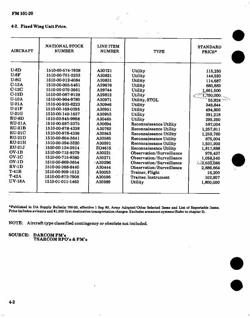
FM 101-20
4-2. Fixed Wing Unit Price.
AIRCRAFT
U-8D U-8F U-8G C-12A C-12C C-12D U-10A U-21A U-21F U-21G RU-8D RU-21A RU-21B RU-21C RU-21D RU-21H RU-21J 0V-1B OV-1C OV-1D RV-1D T-41B T-42A UV-18A
NATIONAL STOCK NUMBER
1510-00-574-7938 1510-00-701-2233 1510-00-912-4084 1510-00-005-5461 1510-00-070-3661 1510-00-087-9129 1510-00-964-9780 1510-00-933-8223 1510-00-169-0295 1510-00-Í40-1627 1510-00-945-9998 1510-00-587-3375 1510-00-878-4338 1510-00-878-4336 1510-00-804-3641 1510-00-394-3320 1520-00-124-0914 1510-00-715-9379 1510-00-715-9380 1510-00-869-3654 1510-00-368-8440 1510-00-929-1012 1510-00-872-7908 1510-01-011-1462
LINE ITEM NUMBER
A30721 A30821 A30831 A29676 A29744 A29812 A30971 A30946 A30951 A30953 A30465 A30694 A30762 A30843 A30585 A30591 Z04615 A30221 A30271
'A30296 A30444 A30053 A30596 A30989
TYPE
Utility Utility Utility Utility Utility Utility Utility, STOL Utility Utility Utility Utility Reconnaissance Utility Reconnaissance Utility Reconnaissance Utility Reconnaissance Utility Reconnaissance Utility Reconnaissance Utility Observation/Surveillance Observation/Surveillance Observation/Surveillance Observation/Surveillance Trainer, Flight Trainer, Instrument Utility
STANDARD PRICE*
115.250 144,593 114,687 680,883
^661,500 17750.000
55,824 348,844 494,800 391,218 295.250 587.004
1,257,811 1,259,760
875.004 1,501,200 1,817,888
976,437 1,058^540
c^2;033,066 2,886,664
16,200 102,907
1.800.000
’Published in DA Supply Bulletin 700-20, effective 1 Sep 80, Army Adopted/Other Selected Items and List of Reportable Items. Price includes avionics and $1,500 first destination transportation charges. Excludes armament systems (Refer to chapter 2).
N OTE : Aircraft type classified contingency or obsolete not included.
SOURCE: DARCOMPM’s TSARCOM RPO’s & PM’s
4-2

FM 101-20
Section IL FLYING HOUR COSTS
4-3. Aircraft Flying Hour Costs.
To obtain current parts, labor and POL flying hour costs contact DA (DALO-AV), AUTOVON 227-0487 or DACA-CA, AUTOVON 225-1104.
Section III. AVIONICS COSTS
4-4. Avionics Estimated Maintenance Cost Factors.
To obtain current date such as labor costs or parts costs on avionics equipment or systems contact CERCOM (DRSEL-ME-E), AUTOVON 992-1685.
SOURCE: DRSEL-ME-E
Section IV. ARMAMENT COSTS
4-5. Airborne Armament Maintenance Costs.
To obtain current labor and parts costs on aircraft/weapon subsystems contact ARRCOM-DRSAR- MAS-SS, AUTOVON 793-5668.
4-3/(4-4 blank)

%

FM 101-20
CHAPTER 5
RESEARCH AND DEVELOPMENT OF MATERIEL
Army aviation research and development is conducted on aircraft systems and in areas not directly related to specific aircraft systems. Research not directly related to aircraft systems includes low speed aerodynamics, structures, and propulsion. Exploratory development is con- ducted in such areas as area fluid dynamics, aeromechanics, flight dynamics, flight loads, air- craft structures and composite materials, power devices, propulsion components, aircraft sur- vivability, aircraft ground support equipment, reliability/maintainability, avionics technology, and aircraft weapons.
5-1. General.
a. Research aircraft are procured in limited quantities to evaluate concepts during the. Research, Exploratory Development and Advanc- ed Development phases of the R&D cycle.
b. Development aircraft systems are aircraft systems proposed for operational use to replace or complement current Army aircraft systems.
5-2. Development Aircraft Systems.
The following development aircraft systems are in order of priority.
5-3. Remotely Piloted Vehicle (RPV) Systems.
a. The remotely piloted vehicle (RPV) system designated YMQM-105 (AQUILA), performs target acquisition, designation, aerial recon- naissance and artillery missions. A small unman- ned air vehicle, including its mission payload, is controlled from a ground control station (GCS) and video imagery and target location informa- tion are returned via an anti-jam link. See figure 5-1 (AQUILA) for typical devployed system.
The system consists of an air vehicle, ground control station (GCS), remote ground terminal (RGT), launch equipment, recovery equipment and support equipment. The small fixed wing air- craft carries a target acquisition and designation system as a mission payload. The current mis- sion payload consists of a stabilized TV sensor with laser rangefinder/designator. The air vehi-
cle and mission payload are controlled from the GCS through the modular integrated communica- tions and navigation system (MICNS). The MICNS consists of airborne and ground data ter- minals that provide an anti-jam command and data link. The ground data terminal (GDT) con- sists of a control unit in the GCS and remote ground terminal (RGT) which tracks, commands and receives data from the air vehicle.
The GCS is the operation center and is housed in a mobile shelter. It includes a mission plan- ning facility, control and display consoles, com- puter and processing equipment and tactical communications equipment. A truck mounted launch subsystem catapults the air vehicle into the air. When the mission is completed, the air vehicle is automatically guided to a truck mounted vertical net recovery subsystem. The support equipment includes ground power generators, maintenance shelter, ground test equipment, trucks, trailers and other equipment.
b. RPV Milestone Schedule:
1. FSED contract award Aug 1979 2. DT II completed Nov 1984 3. OTII completed Mar 1985 4. Production Contract Award Jul 1985 5. Initial IOC Sep 1987
5-4. AHIP Advanced Scout Helicopter (OH-58D).
The AHIP is a single engine rotary wing air- craft designed as a target locator/target designator to operate with other attack helicopters armed with laser guided weapons. AHIP will be armed with MLM or Stinger missiles. (Refer to figure 5-2.)
5-5. Loading and Performance — Typical Mis- sion AHIP.
Not Applicable.
5-6. Performance Notes, AHIP.
Not Applicable.
SOURCE: AVRADCOM-DRCPM-RPV-L
5-1

en to
RCT
y AV
LAUNCHER fia
J» A
RECOVERY SYSTEM
Qi et? CCS
o' CARGO TRUCK
ñ
MAINTENANCE SHELTER
GENERATORS
AV HANDLER
SECTION LEADER'S VEHICLE
Figure 5-1. YMQM-105 (AQUILA) Tjrpical Deployed System
• • • •

• • • •• 5-7. AHIP Characteristics.
Ol
¿a
POWER PLANT
No. & model (1) 250-C30R Mfr Detroit Diesel
Allison Engine Spec. No 907 Reduction Gear Ratio 5.095:1 Tail Pipe Fixed Area Augmentation None Power Turbine to Main
Rotor Gear Ratio 77.60:1
ENGINE RATINGS
Sea Level Standard Conditions
Not Applicable
MISSION AND DESCRIPTION
Advanced Scout Helicopter (AHIP) LOADING
WEIGHTS
LB
The AHIP is being developed primarily for target loca- tion and designation for the laser guided weapons carried by accompanying attack helicopters. Designation and hand off may be conducted around the clock and under adverse weather conditions. The advanced scout features a mast mounted sight containing sensors for forward looking infra-red (FLIR), laser designation and television at normal and low light levels. Two multi-function displays with remote frequency capability present navigation, com- munication and imagery from the sight, easing pilot workload. Additional features include, 3 AXIS SCAS and 2 on board computers enhancing mission capability and reliability.
Empty Basic Design Maximum Combat
Primary Alternate Ferry
FUEL AND OIL
Fuel:
L.F.
TECHNICAL PUBLICATION
AIRFRAME: Not Available
Date of Contract
DEVELOPMENT
October 1981
Grade Spec No. Tanks Location.. Qty
JP4 MIL-T-5624 1 ... Fuselage 104 gal.
usable
ENGINE: Not Available
AVIONICS: Not Available
ARMAMENT:
FEATURES PERSONNEL
Not Available Pilot : 1 Co-Pilot/Sight
Operator 1
Oil (Engine) Spec MIL-L-7808/
MIL-L-23699 No. Tanks 1 Qty 8Qts.
AVIONICS/ARMAMENT
Not Available Refer to Chapter 2
FLYAWAY
NSN 1520-01-125-5476 LINE Z46347
L
FM
101-2
0

T'
Cl
MAST
lim
\m
p ■I i J K 4n 4 IN ■-)
6FT 5.4 IN
, El 12 FT 9.4 IN
6 FT 59 IN
L£L2.7 IN OROP@ BUDE
(STATIC)
WL—
KNEELED GROUND UNE
2 FT 6.1 IN
S'»
LT-i- c: T>
e F1APPING STOP ¡r1 2J IN
35 FT DIA DIRECnON ROTATION
1 FT 6 IN
MAST 10.75
(GROUND REF)
PREGONE APEX
STA 107329 WL 115300 /T1 /
2> PRECONE r 2 FT li IN DIA 4J2//V
1.42 N STA 5 FT 5 IN OIA
Un BFT 6.0IN 1FT6IN
6 FT 5.7 IN
-635 IN
SIGHT REMOVED/BIADES Li0« FOLDED 5.8 IN
5*33 fir« ■ EFT 53 IN 1FT 12 N
8FT9 IN
1 FT 9.4 IN ^ r 3*45.4 STA 108.4
W154.4 BSCGW 4500 LBS
33 FT 10D IN • (KNEELED REF)-
STATIC GROUND UNE (BSOGW)
Figure 5-2. General Arrangement (AHIP)
• • • •
FM
101*20

FM 101-20
APPENDIX A
REFERENCES
ARMY REGULATIONS (AR) (DA RAMP 310-1 )
70-50
95-70
310-50
310-25
570-2
611-201
750-1
Designating and Naming Military Aircraft, Rockets, and Guided Missiles.
Army Aviation Planning Manual.
Authorized Abbreviations and Brevity Codes
Dictionary of United States Army Terms.
Organization and Equipment Authorization Tables - Personnel.
Enlisted Career Management Fields and Military Occupational Specialties.
Army Materiel Maintenance Concepts and Policies.
FIELD MANUALS (FM) (DA PAMP 310-3)
1-105
21-6
21-30
21-60
55-15
55-40
90-1 __
90-4
101-10-1
Army Aviation Techniques and Procedures.
How to Prepare and Conduct Military Training.
Military Symbols.
Visual Signals.
Transportation Reference Data.
Army Combat Service Support Air Transport Operations.
Employment of Army Aviation Units in a High Threat Environment (How to Fight)
Airmobile Operations (How to Fight)
Staff Officers’ Field Manual: Organization, Technical, and Logistical Data (Part I — Unclassified).
TRAINING CIRCULARS (TQ (DA PAMP 310-3)
21-5-7 Training Management in Battalions.
TECHNICAL MANUALS (TM) (DA PAAAP 31 CM)
55-450-8 Air Transport of Supplies and Equipment: External-Transport Procedures.
55-450 series Air Transport of Supplies and Equipment: Internal-Transport Procedures.
A-l
A
■1 FM 101-20
APPENDIX A (CONT.)
55-450-15 Air Movement of Troops and Equipment (Non-Tactical).
SUPPLY BULLETIN(S)
SB 700-20 Army Adopted/Other Items Selected for Authorization/List of Reportable Items.
A-2
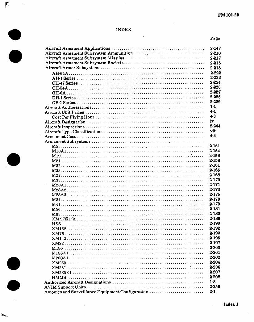
r FM 101-20
INDEX
Page
Aircraft Armament Applications Aircraft Armament Subsystem Ammunition Aircraft Armament Subsystem Missiles Aircraft Armament Subsystem Rockets Aircraft Armor Subsystems
AH-64A AH-1 Series CH-47 Series CH-54A OH-6A UH-1 Series OV-1 Series
Aircraft Authorizations Aircraft Unit Prices
Cost Per Flying Hour Aircraft Designation Aircraft Inspections Aircraft Type Classifications Armament Cost Armament Subsystems
M5 M18A1 M19 M21 M22 M23 M27 M35 M28A1 M28A2 M28A3 M24 M41 M56 M65 XM97E1/2 HSS XM138 XM76 XM142 XM22 M156 M158A1 M200A1 XM260 XM261 XM230E1 : HMMS
Authorized Aircraft Designations AVIM Support Units Avionics and Surveillance Equipment Configuration
2-147 2-210 2-217 2-215 2-218 2-222 2-223 2-224 2-226 2-227 2-228 2-229 1-1 4-1 4-3 iv 2-244 viii 4-3
2-151 2-154 2-156 2-158 2-161 2-165 2-168 2-170 2-171 2-173 2-175 2-178 2-179 2-181 2-183 2-186 2-190 2-192 2-193 2-195 2-197 2-200 2-201 2-202 2-204 2-206 2-207 2-208 1-8 2-256 2-1
Index 1

.'I
FM 101-20
Page
Avionics Cost Basic Annual Flying Hour
Planning Factors Replacement/Crash Damage Factor (Attrition)
Ferrying Shipping Fuel and Oil Consumption Fuel and Oil Cost MACRIT Maintenance Categories Maintenance Man-hours
Direct Man-hours Per Flight Hour Direct Man-hours Technical Inspection
Major Components Personnel Requirements Research and Development
Remotely Piloted Vehicle Shop Sets Standard Aircraft Characteristics/Performance...
AH-64A AH-1G/TH-1G AH-1S (MOD) AH-lS (PROD) AH-1S (EGAS) CH-47A CH-47B CH-47C CH-47D CH-54A CH-54B OH-6A OH-58A OH-58C TH-55A UH-1M UH-1H UH-1V EH-1H EH-1X UH-60A C-12A OV-1B OV-1C OV-1D RV-1D T-41B T-42A U-8F U-10A U-21A/RU-21A RU-21D U-21F
4-3
M2 1- 14 2- 230 2-248 2-246 2-252 2-258
2-250 2- 251 2-1 3- 1
5-1 2-237 1-15 1-17 1-23 1-27 1-29 1-33 1-40 1-42 1-46 1-52 1-57 1-60 1-66 1-73 1-77 1-81 1-85 1-89 1-95 1-98 1-99 1-103 1-107 1-111 1-116 1-122 1-125 1-130 1-134 1-138 1-144 1-149 1-152 1-155
Index 2
à

FM 101-20
\
Page
RU-21B/RU-21C RU-21H RU-21J UV-18A
Tool Kits Tool Sets
1-158 1-161 1-165 1- 169 2- 243 2-243
1
Index3/(lndex 4 blank)


By Order of the Secretary of the Army:
Official:
JOHN A. WICKHAM, JR. General, United States Army
Chief of Staff
ROBERT M. JOYCE Major General, United States Army
The Adjutant General
DISTRIBUTION: Active Army, ARNG, USAR: To be distributed in accordance with DA Form 12-11B,
Requirements for US Army Aviation Planning Manual Part I (U).
frll.S. GOVERNMENT PRINTING OFFICE: 1984-764-120/46
»

i
Á

X e?
RECOMMENDED CHANGES TO EQUIPMENT TECHNICAL PUBLICATIONS
SEaninsioiia® WITH THIS PUBLICATION?
THEN. . JOT DOWN THE DOPE ABOUT IT ON THIS FORM. CAREFULLY TEAR IT OUT. FOLD IT AND DROP IT IN THE MAIL'
FROM (PRINT YOUR UNIT’S COMPLETE ADDRESS)
DATE SENT
PUBLICATION NUMBER
FM 101-20 PUBLICATION DATE
6 Jan 84 PUBLICATION TITLE
US Army Aviation Planning Manual
BE EXACT . PIN-POINT WHERE IT IS
PAGE NO
PARA- GRAPH
FIGURE NO
TABLE NO
IN THIS SPACE TELL WHAT IS WRONG AND WHAT SHOULD BE DONE ABOUT IT:
PRINTED NAME. GRADE OR TITLE. AND TELEPHONE NUMBER SIGN HERE
P| A PORM UM 1 JUL 79 2028-2 PREVIOUS EDITIONS
ARE OBSOLETE.
DRSTS-M Overprint 2, 1 Nov 80.
P S -IF YOUR OUTFIT WANTS TO KNOW ABOUT YOUR RECOMMENDATION MAKE A CARBON COPY OF THIS AND GIVE IT TO YOUR HEADQUARTERS

REVERSE OF OA FORM 3028-2 Reverie of DRSTS-M Overprint 2,
1 Nov 80
COMMANDER
U S ARMY SUPPORT AND AVIATION MATERIEL READINESS COMMAND
ATTN: DRSTS-MPSO
4300 GOODFELLOW BOULEVARD
ST. LOUIS. MO 63130
FILL IN YOUR UNIT'S ADDRESS
5Z FOLD BACK
DEPARTMENT OF THE ARMY
POSTAGE AND FEES PAID DEPARTMENT OF THE ARMY
DOD 314
OFFICIAL BUSINESS PENALTY FOR PRIVATE USE $300
,A
TE
AR A
LO
NG P
ER
FO
RA
TE
D L
INE

RECOMMENDED CHANGES TO EQUIPMENT TECHNICAL PUBLICATIONS
»!
Mure» wmm WITH THIS PUBLICATION?
THEN. . JOT DOWN THE DOPE ABOUT IT ON THIS FORM. CAREFULLY TEAR IT OUT FOLD IT AND DROP IT IN THE MAIL'
PUBLICATION NUMBER
FM 101-20
BE EXACT PIN-POINT WHERE IT IS
PAGE NO
PARA- GRAPH
FIGURE NO
TABLE NO
FROM: (PRINT YOUR UNIT S COMPLETE ADDRESS)
DATE SENT
PUBLICATION DATE
6 Jan 84
PUBLICATION TITLE
US Army Aviation Planning Manual
IN THIS SPACE TELL WHAT IS WRONG AND WHAT SHOULD BE DONE ABOUT IT:
PRINTED NAME. GRADE OR TITLE. AND TELEPHONE NUMBER SIGN HERE
DA 1 JUL*79 2028-2 PREVIOUS EDITIONS ARE OBSOLETE.
DRSTS.M Overprint 2, 1 Nov 80.
P S -IF YOUR OUTFIT WANTS TO KNOW ABOUT YOUR RECOMMENDATION MAKE A CARBON COPY OF THIS AND GIVE IT TO YOUR HEADQUARTERS

REVERSE OF DA FORM 2028-2 R, of DRSTS-M Overprint 2,
1 Nov 80
FILL IN YOUR UNIT'S ADDRESS
DEPARTMENT OF THE ARMY
OFFICIAL BUSINESS PENALTY FOR PRIVATE USE $300
FOLD BACK
POSTAGE AND FEES PAID DEPARTMENT OF THE ARMY
DOD 314
/*
COMMANDER
U S ARMY SUPPORT AND AVIATION MATERIEL READINESS COMMAND
ATTN: DRSTS-MPSD
4300 G00DFELL0W BOULEVARD
ST. LOUIS, MO 63120
I
Á
TU
R R
UH
R P
ER
FO
RA
TE
D L
INE

TE
AR A
LON
C P
hRF
OR
AT
hD U
S h
RECOMMENDED CHANGES TO EQUIPMENT TECHNICAL PUBLICATIONS
X œ WITH THIS PUBLICATION?
THEN. . JOT DOWN THE DOPE ABOUT IT ON THIS FORM, CAREFULLY TEAR IT OUT. FOLD IT AND DROP IT' IN THE MAIL’
FROM (PRINT YOUR UNIT’S COMPLETE ADDRESS)
cra//A/ DO£ .
Co A 3d &*&**'£*& 'S* FT. ’L iAjJAfUiutoob . toa (,3IOñ
DATE SENT
PUBLICATION NUMBER
FM 101-20
PUBLICATION DATE
6 Jan 84
PUBLICATION TITLE
US Army Aviation Planning Manual
BE EXACT. PIN-POINT WHERE IT IS
PAGE NO
bl
PARA- GRAPH
4-/ ¿L
FIGURE NO
TABLE NO
IN THIS SPACE TELL WHAT IS WRONG AND WHAT SHOULD BE DONE ABOUT IT:
¿QJtí JJ - 4*/**-*/«
<UjUU¿t n
4$
Y
y~3
'4¿U. ÂtO'Mÿ.
\f ¿¿£*0 je, - '&&***. CS^JUAX:
.,{) Cía. O-ABAJ ycAtm)
¿s/J
jL 9s6- oo-^ví 3 - 3 oo/. ^ aeJAzt *¿¿¿ <&■.
^
ÜL>A*+ytáL • if&áA* -491A*
A)
7fë£ PRINTED NAME. GRADE OR TITLE. AND TELEPHONE NUMBER
btt, Pfc(at*)3/1* 1/// SIGN HERE ^
-3~6MfJ b»E
DA, '““9 2028-2 PREVIOUS EDITIONS ARE OBSOLETE.
DRSTS^I Overprint 1, 1 Nev 80
PS-IF YOUR OUTFIT WANTS TO KNOW ABOUT YOUR RECOMMENDATION MAKE A CARBON COPY OF THIS AND GIVE IT TO YOUR HEADQUARTERS
\

REVERSE OF DA FORM 2028-2 R, of DRSTS-M Overprint 2,
1 Nov 80
FILL IN YOUR UNIT’S ADDRESS
DEPARTMENT OF THE ARMY
OFFICIAL BUSINESS
PENALTY FOR PRIVATE USE $300
FOLD BACK
POSTAGE AND FEES PAID DEPARTMENT OF THE ARMY
OOO 314 UB.MAIL
V
COMMANDER
U S ARMY SUPPORT AND AVIATION MATERIEL READINESS COMMAND
ATTN i DRSTS-MPSD
4300 GOODFELLOW BOULEVARD
ST. LOUIS, MO 63120
3000 Q3-\A82
TU
R A
LO
RS P
ER
FO
RA
TE
D L
INE

The Metric System and Equivalents
Liaear Matson
centimeter = 10 millimeters = .39 inch decimeter = 10 centimeters = 3.94 inches meter = 10 decimeters = 39.37 inches dekameter = 10 meters = 32.8 feet hectometer = 10 dekameters = 328.08 feet kilometer = 10 hectometers = 3,280.8 feet
Weights
' 1 centigram = 10 milligrams = .15 grain 1 1 decigram = 10 centigrams = 1.54 grains ^ 1 gram = 10 decigram = .035 ounce
1 dekagram = 10 grams = .35 ounce 1 hectogram = 10 dekagrams = 3.52 ounces
> 1 kilogram = 10 hectograms = 2.2 pounds 1 quintal = 100 kilograms = 220.46 pounds
‘ 1 metric ton = 10 quintals =1.1 short tons.
Liquid Matson
1 centiliter = 10 milliters ' = .34 fl. ounce 1 deciliter = 10 centiliters = 3.38 fl. ounces 1 liter = 10 deciliters = 33.81 fl. ounces 1 dekaliter = 10 liters = 2.64 gallons 1 hectoliter = 10 dekaliters = 26.42 gallons Ikiloliter = 10 hectoliters = 264.18 gallons
Squire AfoMsuTB
1 sq. centimeter = 100 sq. millimeters = .155 sq. inch 1 sq. decimeter = 100 sq. centimeters = 15.5 sq. inches 1 sq. meter (centare) = 100 sq. decimeters = 10.76 sq. feet 1 sq. dekameter (are) = 100 sq. meters = 1,076.4 sq. feet 1 sq. hectometer (hectare) = 100 sq. dekameters = 2.47 acres 1 sq. kilometer = 100 sq. hectometers = .386 sq. mile
Cubic Measure
1 cu. centimeter = 1000 cu. millimeters = .06 cu. inch 1 cu. decimeter = 1000 cu. centimeters = 61.02 cu. inches 1 cu. meter = 1000 cu. decimeters = 35.31 cu. feet
Approximate Conversion Factors
To change
inches feet
, yards * miles ) square inches. 1 square feet } square yards f square miles
acres , cubic feet cubic yards fluid ounces
I pints ' quarts gallons
,1 ounces pounds short tons
‘ pound-feet pound-inches
To
centimeters meters meters kilometers square centimeters square meters square meters square kilometers square hectometers cubic meters cubic meters milliliters liters liters liters grams kilograms metric tons newton-meters m A urt s* n _ m A *• a
Multiply by To change To
2.540 ounce-inches • newton-meters .305 centimeters . inches .914 meters feet
1.609 meters yards 6.451 kilometers miles
.093 square centimeters square inches
.836 square meters square feet 2.590 square meters square yards
.405 square kilometers square miles
.028 square hectometers acres
.765 cubic meters cubic feet 29,573 cubic meters cubic yards
.473 milliliters fluid ounces
.946 liters pints 3.785 liters quarts
28.349 liters gallons .454 ■ grams ounces .907 kilograms pounds
1.356 metric tons short tons .11296
Multiply by
.007062 .394
3.280 1.094
. .621 .155
10.764 1.196 .386
2.471 35.315
1.308 .034
2.113 1.057 .264 .035
2.205 1.102
Temperature (Exact)
F Fahrenheit temperature
5/9 (after subtracting 32)
Celsius temperature
C
l-.f,
GJI ! Os
loi I o= i OJ=
' «kl ! «1 ro=
PE
NT
AG
ON LIB
RA
RY