unit objectives differentiate between basic...
TRANSCRIPT

Wired internetworking devices
Unit objectives
Differentiate between basic
internetworking devices
Identify specialized internetworking
devices

Topic A
Topic A: Basic internetworking devices
Topic B: Specialized internetworking
devices

Common internetworking devices

Repeaters
Boost signal from one segment to another
Two types
– Amplifier
– Signal-regenerating

Repeater placement
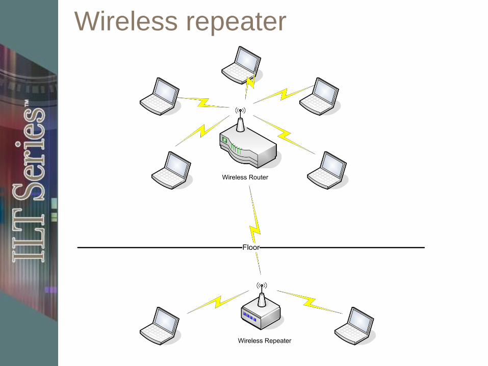
Wireless repeater

Repeater operation
Physical layer
(OSI Layer 1)
Amplifies signal
Amplifies noise
Limited in number
of repeaters per
segment
Intelligent
repeaters
regenerate signal
and are immune to
attenuation
Repeater issues
Signal quality
Time delays
Network traffic
Node limitations

Activity A-1
Discussing internetworking basics
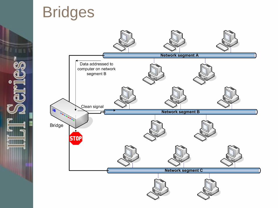
Bridges

Bridge operation
Data Link layer
(OSI Layer 2)
– Specifically MAC
sub-layer
Transparent to
higher-level
protocols
Filter traffic based
on addresses

Bridge types
Heterogeneous (translating)
– Ability to link between dissimilar MAC layer protocols
Encapsulating
– Packages frames of one format into the format of another
– Faster than translation
Learning (transparent)
– Automatically identify devices on the segments they connect
– Listens to replies and creates a table of addresses originating on each segment

Bridge routing management
Two critical issues
– Need to know capacities of bridge
segments
– Routing control to protect against
redundant messages
Two common bridge routing
algorithms
– Spanning tree
– Source routing
Bridge filtering and intelligence
Looks for other patterns within the
frame
Uses patterns to selectively control
forwarding of frames
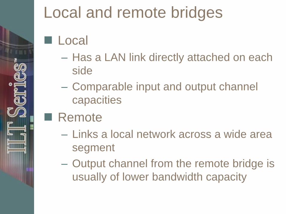
Local and remote bridges
Local
– Has a LAN link directly attached on each
side
– Comparable input and output channel
capacities
Remote
– Links a local network across a wide area
segment
– Output channel from the remote bridge is
usually of lower bandwidth capacity
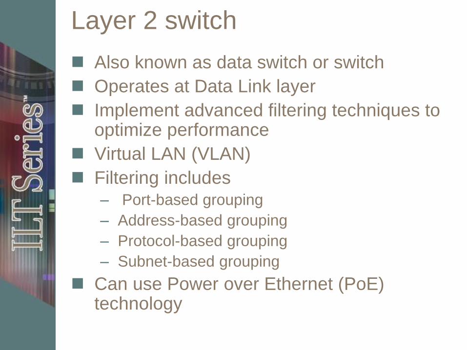
Layer 2 switch
Also known as data switch or switch
Operates at Data Link layer
Implement advanced filtering techniques to optimize performance
Virtual LAN (VLAN)
Filtering includes – Port-based grouping
– Address-based grouping
– Protocol-based grouping
– Subnet-based grouping
Can use Power over Ethernet (PoE) technology

Bridges versus switches
Bridges have fewer ports to connect
network segments
Modern switches have capability for
VLAN trunking
– Virtualize “n” number of network
adapters
– “n” has a theoretical limit of 4096
– “n” typically limited to 1000 different
VLAN network segments
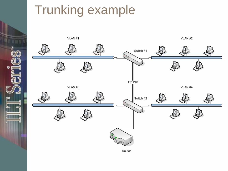
Trunking example

Activity A-2
Identifying types of bridges and switches
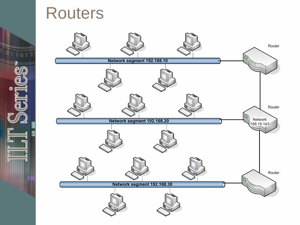
Routers
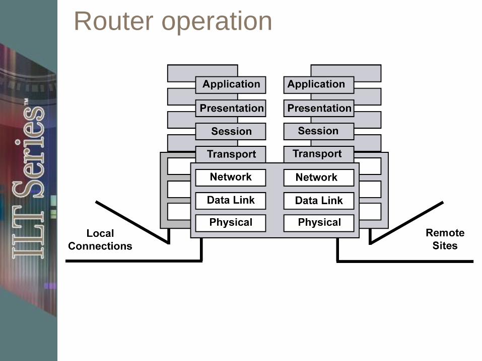
Router operation
About routers
Protocol support
– Early routers supported a single protocol
– Today multiple-protocol routers support
15 to 20 protocols simultaneously
Uses tables to route traffic
– Static or dynamic
Wide area links need
– Flow control
– Multiple-path management
– Routing decision rules
continued

About routers, continued
Wide area connection needs a routable
protocol
Multiple (redundant) paths between
locations provides
– Backup
– Load balancing
– Full use of available bandwidth
Use to subnet
– Increases security
– Reduces traffic congestion
Includes programmable management
features

Router features
Inclusion of
processor/memory/storage
Multiple physical interfaces (ports)
support
Multiple protocol support
Configuration/management
(open/proprietary) interface

Key points
Router connects two or more subnetworks
Router can be configured to support a
single protocol or multiple protocols
Router only processes packets specifically
addressing it as a destination
Packets destined for a locally connected
subnetwork are passed to that network
Packets destined for a remote subnetwork
are passed to the next router in the path
Router that exists in the same subnet as a
host can be configured as a default gateway

Types of routers
Static – Mostly replaced by dynamic
– Manual configuration
– Manual updates
– Can’t compensate for changing environments
Dynamic – Use an Interior Gateway Protocol (IGP) to
communicate with each other RIP
OSPF
IGRP and EIGRP
Path vector protocols
Default gateways
Routing table contents
Destination network IP address
Destination network subnet mask
Router interface used to get to the
network
IP address of the next router in the
path to the destination
Number of hops to the destination
Routing examples
Local destination
Remote destination, next hop known
Remote destination, next hop
unknown
– Destroys packet
– Returns ICMP message
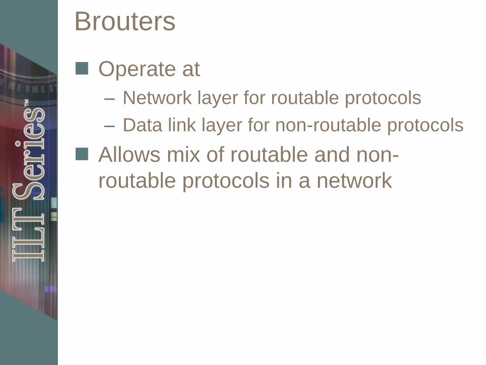
Brouters
Operate at
– Network layer for routable protocols
– Data link layer for non-routable protocols
Allows mix of routable and non-
routable protocols in a network

Bridges vs. routers
Preference for routers in WANs
Bridges can escalate a transient
reliability problem into a serious
network failure
Routers don’t propagate broadcasts
Remote bridges pass on all
broadcasts
Network performance problems can
lead to broadcast storm

Activity A-3
Discussing routers and brouters

Ethernet hub
Hubs used to wire Ethernet star
Operate at Physical layer
Connects devices that use BNC or RJ-45
connector
Easy to configure

Data traffic through a hub

Hub types
Passive
Active
Switching
Intelligent

Activity A-4
Discussing Ethernet devices
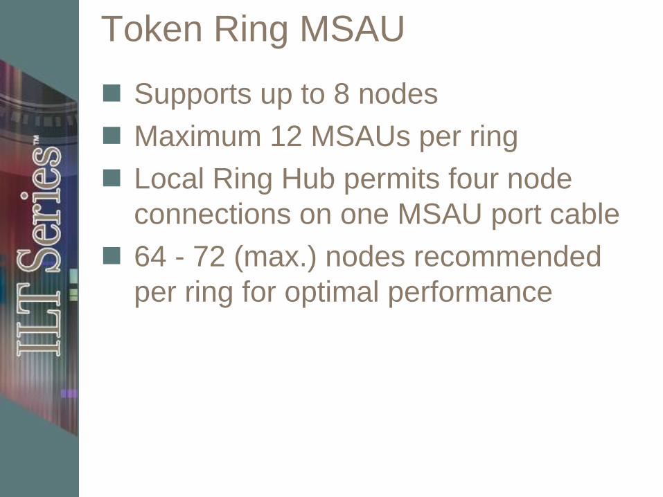
Token Ring MSAU
Supports up to 8 nodes
Maximum 12 MSAUs per ring
Local Ring Hub permits four node
connections on one MSAU port cable
64 - 72 (max.) nodes recommended
per ring for optimal performance

Token Ring distances
Station to MSAU: 45 m
MSAU to MSAU: 120 m
MSAU to repeater: 600 m
Maximum Network Length: 750 m
(Type 1 cabling)
MSAU to Fiber Optic Repeater: 1.5 km

MSAU functions
Looks like a star, works as a ring
Two rings
– One used for token passing between the devices
– Second is loop of all of the MSAU backup paths, known
as a redundant ring
Redundant ring used when there’s a cable break

Media converters
Provides a connection between one
network media type and another
without changing the channel access
method
Typically a small box approximately 3
× 2 × 0.5 in
Has an AUI port on one side and any
one of a number of connectors on the
other side
Also referred to as media filters
Activity A-5
Discussing Token Ring and other devices
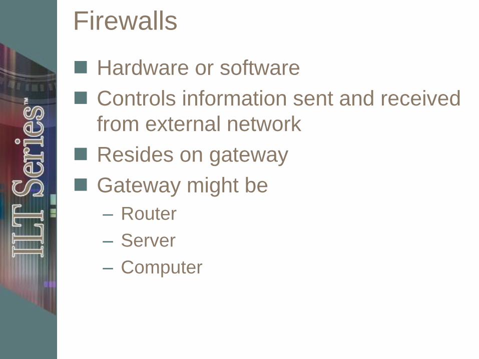
Firewalls
Hardware or software
Controls information sent and received
from external network
Resides on gateway
Gateway might be
– Router
– Server
– Computer

Firewall functions
Filter data packets by – Examining the destination IP address
– Source IP address
– Type of protocol used by the packet
Filter ports so outside clients can’t communicate with inside services listening at these ports
Filter applications so that users inside the firewall can’t use particular service over the Internet
Filter information such as inappropriate Web content for children or employees
Able to: – Set alarms when suspicious activities happen
– Track suspicious activity in log files
Range of variations: – Personal firewalls to protect a single computer
– Expensive firewall solutions for large corporations
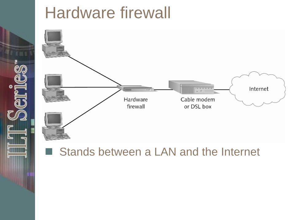
Hardware firewall
Stands between a LAN and the Internet

Software firewall
Good practice for
– “Always on” computers
– Computers connected directly to Internet
Use in conjunction with hardware
firewall
Windows XP SP2 and above includes
Windows Firewall

Proxy server

Port and packet filtering
Port filtering – prevents external
software from using particular ports
Router acting as firewall called
screening router
– Uses stateful inspection
– Allows only internally requested
information through
Can temporarily disable port and
packet filtering, but leaves opening for
attack

Activity A-6
Examining Firewall products

Topic B
Topic A: Basic internetworking devices
Topic B: Specialized internetworking
devices
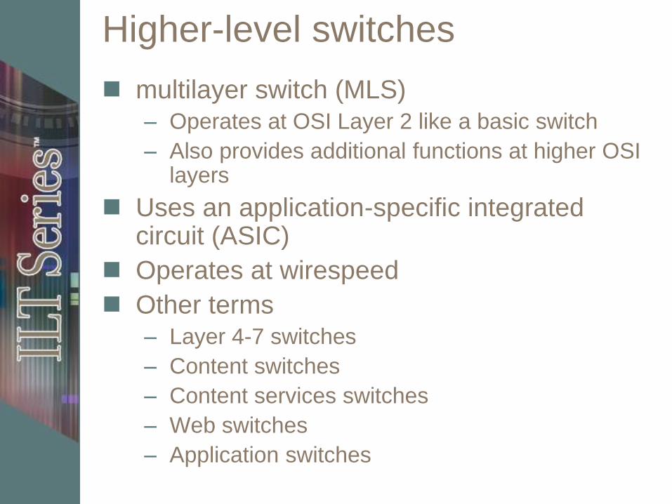
Higher-level switches
multilayer switch (MLS) – Operates at OSI Layer 2 like a basic switch
– Also provides additional functions at higher OSI layers
Uses an application-specific integrated circuit (ASIC)
Operates at wirespeed
Other terms – Layer 4-7 switches
– Content switches
– Content services switches
– Web switches
– Application switches
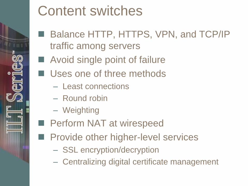
Content switches
Balance HTTP, HTTPS, VPN, and TCP/IP
traffic among servers
Avoid single point of failure
Uses one of three methods
– Least connections
– Round robin
– Weighting
Perform NAT at wirespeed
Provide other higher-level services
– SSL encryption/decryption
– Centralizing digital certificate management

Activity B-1
Researching multilayer switches

IDS and IPS
IDS installed inside your network
– Monitors internal traffic and traffic that
has passed through your firewall
IPS installed on perimeter of network
– Monitors for and stops threats before
they are passed on your network
Both are recommended
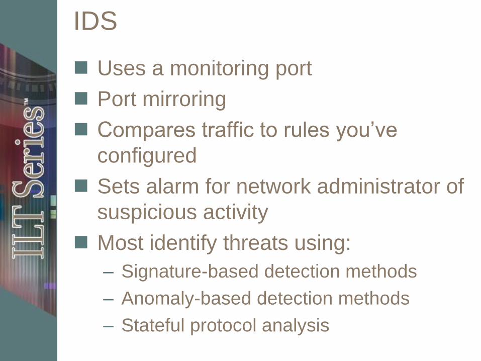
IDS
Uses a monitoring port
Port mirroring
Compares traffic to rules you’ve
configured
Sets alarm for network administrator of
suspicious activity
Most identify threats using:
– Signature-based detection methods
– Anomaly-based detection methods
– Stateful protocol analysis

Malicious traffic detected by IDS
Network attacks against services
Data-driven attacks on applications
Host-based attacks such as
unauthorized logins
Malware such as viruses, Trojan
horses, and worms

IPS
IPS can shut down suspicious traffic on the wire by – Terminating network connection or user session
– Blocking access to targeted host, service, or application from specific user account, IP address, or other attribute
– Blocking all access to targeted host, service, or application
– Reconfiguring other devices, such as a firewall or router, to block an attack
Some higher-end IPS devices can – Apply security patches for known vulnerability to
network hosts
– Remove malicious content of an attack

Activity B-2
Examining IDS and IPS products

Traffic shapers
Also called a bandwidth shaper
Software that controls network traffic
to
– Optimize performance
– Increase usable bandwidth
Configure by categorizing traffic and
then setting rules for categories
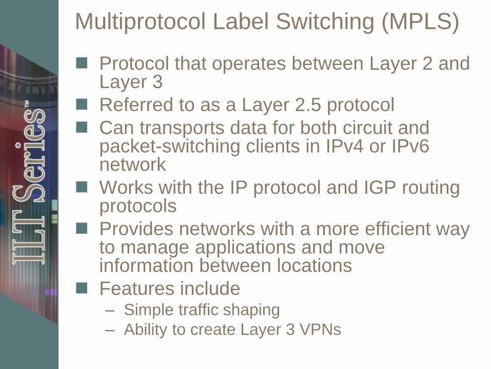
Multiprotocol Label Switching (MPLS)
Protocol that operates between Layer 2 and Layer 3
Referred to as a Layer 2.5 protocol
Can transports data for both circuit and packet-switching clients in IPv4 or IPv6 network
Works with the IP protocol and IGP routing protocols
Provides networks with a more efficient way to manage applications and move information between locations
Features include – Simple traffic shaping
– Ability to create Layer 3 VPNs
Activity B-3
Comparing traffic shaper configuration
Multifunction network devices
Combines several device functions
into one
Saves space
More complicated management
Creates single point of failure risk

Unit summary
Differentiated between basic
internetworking devices
Identified specialized internetworking
devices