unit i site investigation and selection of … · at the end of this course student acquires the...
TRANSCRIPT
Sl.No Contents Page No.
CE6502 FOUNDATION ENGINEERING
UNIT I SITE INVESTIGATION AND SELECTION OFFOUNDATION
1.1 TYPES OF BORING 3
1.2 TYPES OF SAMPLES 6
1.3 IN-SITU TESTS GENERAL 8
1.4 PENETROMETER TESTS 9
1.5 STATIC CONE PENETRATION TEST 12
UNIT II SHALLOW FOUNDATION2.1 INTRODUCTION
22
2.2 DIFFERENT TYPES OF FOOTINGS 222.3 METHODS OF DETERMINING BEARING CAPACITY 23
UNIT III FOOTINGS AND RAFTS
3.1 COMBINED FOOTING 54
UNIT IV PILE FOUNDATION
4.1 DESIGN METHODOLOGY FOR PILES 73
4.2 CLASSIFICATION OF PILES. 73
4.3 POINTS TO BE CONSIDERED FOR CHOOSING PILES 73
4.4 PILES IN SAND 77
4.5 SETTLEMENT OF PILE GROUPS 78
UNIT V RETAINING WALLS
5.1 RETAINING WALL 81
5.2 DIFFERENT TYPES OF RETAINING STRUCTURES 81
5.3 COUNTERFORT RETAINING WALL 83
T SHARMILA 2015-2016 Page 1

CE2305 FOUNDATION ENGINEERING L T P C 3 0 0 3 OBJECTIVE
At the end of this course student acquires the capacity to assess the soil
condition at a given location in order to sugest suitable foundation and also gains the knowledge to design various foundations. UNIT I SITE INVESTIGATION AND SELECTION OF FOUNDATION 9 Scope and objectives – Methods of exploration-auguring and boring – Water boring and rotatory drilling – Depth of boring – Spacing of bore hole - Sampling – Representative and undisturbed sampling – sampling techniques – Split spoon sampler, Thin tube sampler, Stationary piston sampler – Bore log report – Penetration tests (SPT and SCPT) – Data interpretation (Strength parameters and Liquefaction potential) – Selection of foundation based on soil condition. UNIT II SHALLOW FOUNDATION 9 Introduction – Location and depth of foundation – codal provisions – bearing capacity of shallow foundation on homogeneous deposits – Terzaghi’s formula and BIS formula – factors affecting bearing capacity – problems - Bearing Capacity from insitu tests (SPT, SCPT and plate load) – Allowable bearing pressure, Settlement – Components of settlement – Determination of settlement of foundations on granular and clay deposits – Allowable settlements – Codal provision – Methods of minimising settlement, differential settlement. UNIT III FOOTINGS AND RAFTS 9 Types of foundation – Contact pressure distribution below footings and raft - Isolated
T SHARMILA 2015-2016 Page 2
CE6502-FOUNDATION ENGINEERING YEAR:III/SEM:V CIVIL ENGINEERING

and combined footings – Types and proportioning - Mat foundation– Types, applications uses and proportioning-- floating foundation. UNIT IV PILES 9 Types of piles and their function – Factors influencing the selection of pile – Carrying capacity of single pile in granular and cohesive soil - Static formula - dynamic formulae (Engineering news and Hiley’s) – Capacity from insitu tests (SPT and SCPT) – Negative skin friction – uplift capacity – Group capacity by different methods (Feld’s rule, Converse Labarra formula and block failure criterion) – Settlement of pile groups – Interpretation of pile load test – Forces on pile caps – under reamed piles – Capacity under compression and uplift. UNIT V RETAINING WALLS 9 Plastic equilibrium in soils – active and passive states – Rankine’s theory – cohesionless and cohesive soil - Coloumb’s wedge theory – condition for critical failure plane - Earth pressure on retaining walls of simple configurations – Graphical methods (Rebhann and Culmann) - pressure on the wall due to line load – Stability of retaining walls. TOTAL: 45 PERIODS TEXT BOOKS 1. Murthy, V.N.S, “Soil Mechanics and Foundation Engineering”, UBS Publishers Distribution Ltd, New Delhi, 1999. 2. Gopal Ranjan and Rao, A.S.R. ”Basic and Applied Soil Mechanics”, Wiley Eastern Ltd., New Delhi (India), 2003. REFERENCES 1. Das, B.M. “Principles of Foundation Engineering (Fifth edition), Thomson Books /
T SHARMILA 2015-2016 Page 3
CE6502-FOUNDATION ENGINEERING YEAR:III/SEM:V CIVIL ENGINEERING
COLE, 2003 2. Bowles J.E, “Foundation analysis and design”, McGraw-Hill, 1994 3. Punmia, B.C., “Soil Mechanics and Foundations”, Laxmi publications pvt. Ltd., New Delhi, 1995. 4. Venkatramaiah,C.”Geotechnical Engineering”, New Age International Publishers, New Delhi, 1995
UNIT I SITE INVESTIGATION AND SELECTION OF FOUNDATION 9
1.Displacement borings
It is combined method of sampling & boring operation. Closed bottom sampler, slit cup, or piston type is forced in to the ground up to the desired depth. Then the sampler is detached from soil below it, by rotating the piston, & finally the piston is released or withdrawn. The sampler is then again forced further down & sample is taken. After withdrawal of sampler & removal of sample from sampler, the sampler is kept in closed condition & again used for another depth.
Features :
Simple and economic method if excessive caving does not occur. Therefore not suitable for loose sand.
Major changes of soil character can be detected by means of penetration resistance.
These are 25mm to 75mm holes.
It requires fairly continuous sampling in stiff and dense soil, either to protect the sampler from damage or to avoid objectionably heavy construction pit.
2.Wash boring:
It is a popular method due to the use of limited equipments. The advantage of this is the use of inexpensive and easily portable handling and drilling equipments. Here first an open hole is formed on the ground so that the soil sampling or rock
1.1.Types of boring
T SHARMILA 2015-2016 Page 4
CE6502-FOUNDATION ENGINEERING YEAR:III/SEM:V CIVIL ENGINEERING
drilling operation can be done below the hole. The hole is advanced by chopping and twisting action of the light bit. Cutting is done by forced water and water jet under pressure through the rods operated inside the hole.
In India the “Dheki” operation is used, i.e., a pipe of 5cm diameter is held vertically and filled with water using horizontal lever arrangement and by the process of suction and application of pressure, soil slurry comes out of the tube and pipe goes down. This can be done upto a depth of 8m –10m (excluding the depth of hole already formed beforehand)
Just by noting the change of colour of soil coming out with the change of soil character can be identified by any experienced person. It gives completely disturbed sample and is not suitable for very soft soil, fine to medium grained cohesionless soil and in cemented soil.
V
T SHARMILA 2015-2016 Page 5
CE6502-FOUNDATION ENGINEERING YEAR:III/SEM:V CIVIL ENGINEERING

1.1 Planning For Subsurface Exploration
The planning of the site exploration program involves location and depth of borings, test pits or other methods to be used, and methods of sampling and tests to be carried out. The purpose of the exploration program is to determine, within practical limits, the stratification and engineering properties of the soils underlying the site. The principal properties of interest will be the strength, deformation, and hydraulic characteristics. The program should be planned so that the maximum amount of information can be obtained at minimum cost. In the earlier stages of an investigation, the information available is often inadequate to allow a firm and detailed plan to be made. The investigation is therefore performed in the following phases:
1. Fact finding and geological survey Reconnaissance
1. Preliminary exploration
2. Detailed exploration
3. Special exploration
1. Fact finding and geological survey
Assemble all information on dimensions, column spacing, type and use of structure, basement requirements, and any special architectural considerations of the proposed building. Foundation regulations in the local building code should be consulted for any special requirements. For bridges the soil engineer should have access to type and span lengths as well as pier loadings. This information will indicate any settlement limitations, and can be used to estimate foundation loads.
2. Reconnaissance
This may be in the form of a field trip to the site which can reveal information on the type and behavior of adjacent sites and structures such as cracks, noticeable sags, and possibly sticking doors and windows. The type of local existing structure may influence, to a considerable extent, the exploration program and the best foundation type for the proposed adjacent structure. Since nearby existing structures must be maintained, excavations or vibrations will have to be carefully controlled. Erosion in existing cuts (or ditches) may also be observed. For highways, run off patterns , as well as soil stratification to the depth of the
T SHARMILA 2015-2016 Page 6
CE6502-FOUNDATION ENGINEERING YEAR:III/SEM:V CIVIL ENGINEERING

erosion cut , may be observed. Rock outcrops may give an indication of the presence or the depth of bedrock.
3. Auger boring
This method is fast and economical, using simple, light, flexible and inexpensive instruments for large to small holes. It is very suitable for soft to stiff cohesive soils and also can be used to determine ground water table. Soil removed by this is disturbed but it is better than wash boring, percussion or rotary drilling. It is not suitable for very hard or cemented soils, very soft soils, as then the flow into the hole can occur and also for fully saturated cohesionless soil.
Change in the stress condition,
Change in the water content an
Disturbed samples: The structure of the soil is disturbed to the considerable degree by the action of the boring tools or the excavation equipments. The disturbances can be classified in following basic types:
Change in the stress condition,
Change in the water content and the void ratio,
In general soil samples are categorized as shown in fig. 1.5
1.2.Types of samples Disturbed samples: The structure of the soil is disturbed to the considerable degree by the action of the boring tools or the excavation equipments. The disturbances can be classified in following basic types:
T SHARMILA 2015-2016 Page 7
CE6502-FOUNDATION ENGINEERING YEAR:III/SEM:V CIVIL ENGINEERING

Disturbance of the soil structure,
Chemical changes,
Mixing and segregation of soil constituents The causes of the disturbances are listed below:
Method of advancing the borehole,
Mechanism used to advance the sampler,
Dimension and type of sampler,
Procedure followed in sampling and boring. Undisturbed samples: It retains as
closely as practicable the true insitu structure and water content of the soil. For
undisturbed sample the stress changes can not be avoided. The following
requirements are looked for:
No change due to disturbance of the soil structure,
No change in void ratio and water content,
No change in constituents and chemical properties.
4 Requirement of good sampling process Inside clearance ratio
The soil is under great stress as it enters the sampler and has a
tendency to laterally expand. The inside clearance should be large enough to allow
a part of lateral expansion to take place, but it should not be so large that it permits
excessive deformations and causes disturbances of the sample. For good sampling
process, the inside clearance ratio should be within 0.5 to 3 %. For sands silts and
clays, the ratio should be 0.5 % and for stiff and hard clays (below water table), it
T SHARMILA 2015-2016 Page 8
CE6502-FOUNDATION ENGINEERING YEAR:III/SEM:V CIVIL ENGINEERING

should be 1.5 %. For stiff expansive type of clays, it should be 3.0 %. area ratio
Recovery ratio
Where, L is the length of the sample within the tube,
H is the depth of penetration of the sampling tube.
It represents the disturbance of the soil sample. For good sampling the recovery ratio should be 96 to 98 %.
Wall friction can be reduced by suitableinside clearance, smooth finish and oiling.
The non-returned wall should have large orifice to allow air and water to escape.
Penetrometer test
Pressuremeter test
Vane shear testPlate load test
1.3.In-situ tests General The in situ tests in the field have the advantage of
testing the soils in their natural, undisturbed condition. Laboratory tests, on the
other hand, make use of small size samples obtained from boreholes through
samplers and therefore the reliability of these depends on the quality of the so
called ‘undisturbed' samples. Further, obtaining undisturbed samples from non-
cohesive, granular soils is not easy, if not impossible. Therefore, it is common
practice to rely more on laboratory tests where cohesive soils are concerned.
Further, in such soils, the field tests being short duration tests, fail to yield
meaningful consolidation settlement data in any case. Where the subsoil strata
are essentially non-cohesive in character, the bias is most definitely towards field
tests. The data from field tests is used in empirical, but time-tested correlations to
predict settlement of foundations. The field tests commonly used in subsurface
investigation are:
T SHARMILA 2015-2016 Page 9
CE6502-FOUNDATION ENGINEERING YEAR:III/SEM:V CIVIL ENGINEERING

Standard penetration test (SPT)
Static cone penetration test (CPT)
Dynamic cone penetration test (DCPT) Standard penetration test
The standard penetration test is carried out in a borehole, while the DCPT and SCPT are carried out without a borehole. All the three tests measure the resistance of the soil strata to penetration by a penetrometer. Useful empirical correlations between penetration resistance and soil properties are available for use in foundation design.
This is the most extensively used penetrometer test and employs a split-spoon sampler, which consists of a driving shoe, a split-barrel of circular cross-section which is longitudinally split into two parts and a coupling. IS: 2131-1981 gives the standard for carrying out the test.
Procedure
The borehole is advanced to the required depth and the bottom cleaned.
The split-spoon sampler, attached to standard drill rods of required length is
lowered into the borehole and rested at the bottom
. The split-spoon sampler is driven into the soil for a distance of 450mm by blows
of a drop hammer (monkey) of 65 kg falling vertically and freely from a height of
750 mm. The number of blows required to penetrate every 150 mm is recorded
while driving the sampler. The number of blows required for the last 300 mm of
penetration is added together and recorded as the N value at that particular depth of
the borehole. The number of blows required to effect the first 150mm of
penetration, called the seating drive, is disregarded. The split-spoon sampler is
then withdrawn and is detached from the drill rods. The split-barrel is
disconnected from the cutting shoe and the coupling. The soil sample collected
Geophysical methods
1.4. Penetrometer Tests :
T SHARMILA 2015-2016 Page 10
CE6502-FOUNDATION ENGINEERING YEAR:III/SEM:V CIVIL ENGINEERING

inside the split barrel is carefully collected so as to preserve the natural moisture
content and transported to the laboratory for tests. Sometimes, a thin liner is
inserted within the split-barrel so that at the end of the SPT, the liner containing
the soil sample is sealed with molten wax at both its ends before it is taken away
to the laboratory. The SPT is carried out at every 0.75 m vertical intervals in a
borehole. This can be increased to 1.50 m if the depth of borehole is large. Due to
the presence of boulders or rocks, it may not be possible to drive the sampler to a
distance of 450 mm. In such a case, the N value can be recorded for the first 300
mm penetration. The boring log shows refusal and the test is halted if
50 blows are required for any 150mm penetration
100 blows are required for 300m penetration
10 successive blows produce no advance.
Precautions
The drill rods should be of standard specification and should not be in bent
condition.
The split spoon sampler must be in good condition and the cutting shoe
must be free from wear and tear.
The drop hammer must be of the right weight and the fall should be free,
frictionless and vertical. The SPT is carried out at every 0.75 m vertical
intervals in a borehole. This can be increased to 1.50 m if the depth of
borehole is large. Due to the presence of boulders or rocks, it may not be
possible to drive the sampler to a distance of 450 mm. In such a case, the N
value can be recorded for the first 300 mm penetration. The boring log
shows refusal and the test is halted if
50 blows are required for any 150mm penetration
T SHARMILA 2015-2016 Page 11
CE6502-FOUNDATION ENGINEERING YEAR:III/SEM:V CIVIL ENGINEERING

100 blows are required for 300m penetration 10 successive blows
produce no advance.
Precautions
The drill rods should be of standard specification and should not be in bent
condition.
The split spoon sampler must be in good condition and the cutting shoe
must be free from wear and tear.
The drop hammer must be of the right weight and the fall should be free,
frictionless and vertical. The height of fall must be exactly 750 mm. Any change
from this will seriously affect the N value.
The bottom of the borehole must be properly cleaned before the test is
carried out. If this is not done, the test gets carried out in the loose, disturbed
soil and not in the undisturbed soil. When a casing is used in borehole, it
should be ensured that the casing is driven just short of the level at which the
SPT is to be carried out. Otherwise, the test gets carried out in a soil plug
enclosed at the bottom of the casing.
When the test is carried out in a sandy soil below the water table, it must be
ensured that the water level in the borehole is always maintained slightly above
the ground water level. If the water level in the borehole is lower than the
ground water level, ‘quick' condition may develop in the soil and very low N
values may be recorded. In spite of all these imperfections, SPT is still
extensively used because the test is simple and relatively economical.
it is the only test that provides representative soil samples both for visual
inspection in the field and for natural moisture content and classification tests in
the laboratory. SPT values obtained in the field for sand have to be
corrected before they are used in empirical correlations and design charts. IS:
2131-1981 recommends that the field value of N be corrected for two effects,
namely, (a) effect of overburden pressure, and (b) effect of dilatancy. (a)
Correction for overburden pressure
T SHARMILA 2015-2016 Page 12
CE6502-FOUNDATION ENGINEERING YEAR:III/SEM:V CIVIL ENGINEERING

Several investigators have found that the penetration resistance or the N value in a granular soil is influenced by the overburden pressure. Of two granular soils possessing the same relative density but having different confining pressures, the one with a higher confining pressure gives a higher N value. Since the confining pressure (which is directly proportional to the overburden pressure) increases with depth, the N values at shallow depths are underestimated and the N values at larger depths are overestimated. To allow for this, N values recorded from field tests at different effective overburden pressures are corrected to a standard effective overburden pressure.
For finding combine cone friction resistance, the shearing strength of the soil qs ,
and tip resistance qc is noted in gauge & added to get the total strength
LimitationsThis test is unsuitable for gravelly soil & soil for having SPT N value
greater than 50. Also in dense sand anchorage becomes to cumbersome &
expensive & for such cases Dynamic SPT can be used. This test is also unsuitable
for field operation since erroneous value obtained due to presence of brick bats,
loose stones etc.
Geophysical exploration General Overview Geophysical exploration may be
used with advantage to locate boundaries between different elements of the subsoil
as these procedures are based on the fact that the gravitational, magnetic, electrical,
radioactive or elastic properties of the different elements of the subsoil may be
different. Differences in the gravitational, magnetic and radioactive properties of
1.5.Static cone penetration test At field SCPT is widely used of recording variation in the in-situ penetration resistance of soil in cases where in-situ density
is disturbed by boring method & SPT is unreliable below water table. The test is
very useful for soft clays, soft silts, medium sands & fine sands. Procedure By
this test basically by pushing the standard cone at the rate of 10 to 20 mm/sec in to
the soil and noting the friction, the strength is determined. After installing the
equipment as per IS-4968, part III the sounding rod is pushed in to the soil and the
driving is operated at the steady rate of 10 mm/sec approximately so as to advance
the cone only by external loading to the depth which a cone assembly available.
T SHARMILA 2015-2016 Page 13
CE6502-FOUNDATION ENGINEERING YEAR:III/SEM:V CIVIL ENGINEERING

deposits near the surface of the earth are seldom large enough to permit the use of
these properties in exploration work for civil engineering projects. However, the
resistivity method based on the electrical properties and the seismic refraction
method based on the elastic properties of the deposits have been used widely in
large civil engineering projects. Different methods of geophysical explorations 1
Electrical resistivity methodElectrical resistivity method is based on the
difference in the electrical conductivity or the electrical resistivity of different
soils. Resistivity is defined as resistance in ohms between the opposite phases of a
unit cube of a material.
is resistivity in ohm-cm,
R is resistance in ohms,
A is the cross sectional area (cm 2),
L is length of the conductor (cm).
The resistivity values of the different soils are listed in table 1.4
Material Resistivity ( -cm)
Massive rock > 400 Shale and clay 1.0
Seawater 0.3 Wet to moist clayey
soils 1.5 - 3.0
Table 1.4 : Resistivity of different materials
Procedure
The set up for the test is given in figure 1.13. In this method, the electrodes are driven approximately 20cms in to the ground and a dc or a very low frequency ac
T SHARMILA 2015-2016 Page 14
CE6502-FOUNDATION ENGINEERING YEAR:III/SEM:V CIVIL ENGINEERING

current of known magnitude is passed between the outer (current) electrodes, thereby producing within the soil an electrical field and the boundary conditions. The electrical potential at point C is Vc and at point D is V d which is measured by means of the inner (potential) electrodes respectively.
---------(1.1.1) ---------(1.1.2 )
where,
is resistivity,
I is current,
, , and are the distances between the various electrodes as shown in fig. 1.13.
Potential difference between C and D = = - = -----
---- ( 1.1.3 ) --------- ( 1.1.4 ) If
then resistivity is given as, ---------( 1.1.5 )
where ,
Resistance
Thus, the apparent resistivity of the soil to a depth
approximately equal to the spacing of the electrode can be computed. The resistivity unit is often so designed that the apparent resistivity can be read directly on the potentiometer.
T SHARMILA 2015-2016 Page 15
CE6502-FOUNDATION ENGINEERING YEAR:III/SEM:V CIVIL ENGINEERING

In “resistivity mapping” or “transverse profiling” the electrodes are moved from place to place without changing their spacing, and the apparent resistivity and any anomalies within a depth equal to the spacing of the electrodes can thereby be determined for a number of points.
approximately equal to the spacing of the electrode can be computed. The resistivity unit is often so designed that the apparent resistivity can be read directly on the potentiometer.
In “resistivity mapping” or “transverse profiling” the electrodes are moved from place to place without changing their spacing, and the apparent resistivity and any anomalies within a depth equal to the spacing of the electrodes can thereby be determined for a number of points.
Seismic refraction method General This method is based on the fact that
seismic waves have different velocities in different types of soils (or rock) and
besides the wave refract when they cross boundaries between different types of
soils. In this method, an artificial impulse are produced either by detonation of
explosive or mechanical blow with a heavy hammer at ground surface or at the
shallow depth within a hole. These shocks generate three types of waves.
Longitudinal or compressive wave or primary (p) wave, Transverse or shear
waves or secondary (s) wave, Surface waves.
It is primarily the velocity of longitudinal or the compression waves which is
utilized in this method. The equation for the velocity of the p-waves and s-
waves is given as,
------- (1.2.1) ------- (1.2.2)
Where,
E is the dynamic modulus of the soil,
is the Poisson's ratio,
T SHARMILA 2015-2016 Page 16
CE6502-FOUNDATION ENGINEERING YEAR:III/SEM:V CIVIL ENGINEERING

is density and,
G is the dynamic shear modulus.
v These waves are classified as direct, reflected and refracted waves. The direct
wave travel in approximately straight line from the source of impulse. The
reflected and refracted wave undergoes a change in direction when they encounter
a boundary separating media of different seismic velocities (Refer fig. 1.19). This
method is more suited to the shallow explorations for civil engineering purpose.
The time required for the impulse to travel from the shot point to various points on
the ground surface is determined by means of geophones which transform the
vibrations into electrical currents and transmit them to a recording unit or
oscillograph, equipped with a timing mechanism. Assumptionshyj
METHODS OF ANALYSIS
LIMIT EQUILIBRIUM
The so-called limit equilibrium method has traditionally being used to obtain approximate solutions for the stability problems in soil mechanics. The method entails a assumed failure surface of various simple shapes—plane, circular, log spiral. With this assumption, each of the stability problems is reduced to one of finding the most dangerous position of the failure or slip surface of the shape chosen which may not be particularly well founded, but quite often gives acceptable results. In this method it is also necessary to make certain assumptions regarding the stress distribution along the failure surface such that the overall equation of equilibrium, in terms of stress resultants, may be written for a given problem. Therefore, this simplified method is used to solve various problems by simple statics. Although the limit equilibrium technique utilizes the basic concept of upper-bound rules.
T SHARMILA 2015-2016 Page 17
CE6502-FOUNDATION ENGINEERING YEAR:III/SEM:V CIVIL ENGINEERING

Of Limit Analysis, that is, a failure surface is assumed and a least answer is sought, it does not meet the precise requirements of upper bound rules, so it is not a upper bound. The method basically gives no consideration to soil kinematics, and equilibrium conditions are satisfied in a limited sense. It is clear then that a solution obtained using limit equilibrium method is not necessarily upper or lower bound. However, any upper-bound limit analysis solution will be obviously limit equilibrium solution.
INTRODUCTION
Partly for the simplicity in practice and partly because of the historical development of deformable of solids, the problems of soil mechanics are often divided into two distinct groups – the stability problems and elasticity problems. The stability problems deal with the conditions of ultimate failure of mass of soil. Problems of earth pressure, bearing capacity, and stability of slopes most often are considered in this category. The most important feature of such problems is the determination of the loads which will cause the failure of the soil mass. Solutions of these problems are done using the theory of perfect elasticity. The elasticity problems on the other hand deal with the stress or deformation of the soil where no failure of soil mass is involved. Stresses at points in a soil mass under the footing, or behind a retaining wall, deformation around tunnels or excavations, and all settlement problems belong to this category. Solutions to these problems are obtained by using the theory of linear elasticity.
Intermediate between the elasticity and stability problems are the problems mentioned above are the problems known as progressive failure. Progressive failure problems deal with the elastic- plastic transition from the initial linear elastic state to the ultimate failure state of the soil by plastic flow. The following section describes some of the methods of analysis which are unique with respect to each other.
DIFFERENT METHODS OF ANALYSIS
T SHARMILA 2015-2016 Page 18
CE6502-FOUNDATION ENGINEERING YEAR:III/SEM:V CIVIL ENGINEERING
There are basically four methods of analysis:
Limit Equilibrium. Limit Analysis. Method of Characteristics. Finite Element / Discrete Element Method. THEOREMS
There are two theorems which are used for the various analyses. Some follow one theorem while some methods of analysis follow the other. They are the upper bound and the lower bound theorems.
In the Upper bound theorem , loads are determined by equating the external work to the internal work in an assumed deformation mode that satisfies:
Boundary deformation pattern.
Strain and velocity compatibility conditions.
These are kinematically admissible solutions. This analysis gives the maximum value for a particular parameter.
In the Lower bound theorem , loads are determined from the stress distribution that satisfies:
Stress equilibrium conditions.
Stress boundary conditions.
Nowhere it violates the yield condition.
These are statically admissible solutions. This analysis gives the minimum value for a particular parameter.
T SHARMILA 2015-2016 Page 19
CE6502-FOUNDATION ENGINEERING YEAR:III/SEM:V CIVIL ENGINEERING
However by assuming different failure surfaces the difference between the values obtained the upper and lower bound theorems can be minimized.
Rankine earth pressure ----------(3) where is the unit
weight of the soil ----------(4)
along a horizontal plane.
at a depth x, integrating equation (3) and (4),
Boundary conditions:
if there is no surcharge, C=0, D=0 at x=0.
.
Hence (active conditions) or (passive conditions)
This implies that in passive case, and in active case .where is the inclination of the major principle stress with the x direction.
Determination of earth pressure coefficients
T SHARMILA 2015-2016 Page 20
CE6502-FOUNDATION ENGINEERING YEAR:III/SEM:V CIVIL ENGINEERING

(for active case, )
= ---------(5) ---------(6) from eqn(5) and (6),
coefficient of active earth pressure similarly, in the passive case ,
----------(7) ----------(8) from eqn(7) and (8), coefficient of
passive earth pressure Inclination of failure plane
The failure planes at particular plane will make an angle of with the direction of major principal stress.
Fig .3.7 Inclination of failure planes
Inclined Ground
T SHARMILA 2015-2016 Page 21
CE6502-FOUNDATION ENGINEERING YEAR:III/SEM:V CIVIL ENGINEERING

Considering the forces in the u and v directions,
---------( 9 ) ---------(10 )
dividing eqn 9 by 10 and simplifying ,
T SHARMILA 2015-2016 Page 22
CE6502-FOUNDATION ENGINEERING YEAR:III/SEM:V CIVIL ENGINEERING
thus,
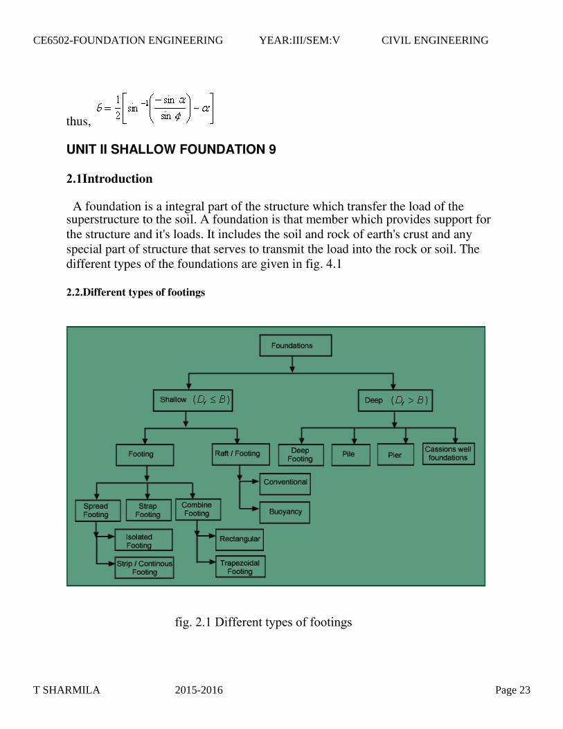
superstructure to the soil. A foundation is that member which provides support for the structure and it's loads. It includes the soil and rock of earth's crust and any special part of structure that serves to transmit the load into the rock or soil. The different types of the foundations are given in fig. 4.1
UNIT II SHALLOW FOUNDATION 9
2.1Introduction
A foundation is a integral part of the structure which transfer the load of the
2.2.Different types of footings
fig. 2.1 Different types of footings
T SHARMILA 2015-2016 Page 23
CE6502-FOUNDATION ENGINEERING YEAR:III/SEM:V CIVIL ENGINEERING
the bearing capacity can be listed as follows: Presumptive Analysis Analytical
Methods Plate Bearing Test Penetration Test Modern Testing Methods
Centrifuge TestPrandtl's Analysis
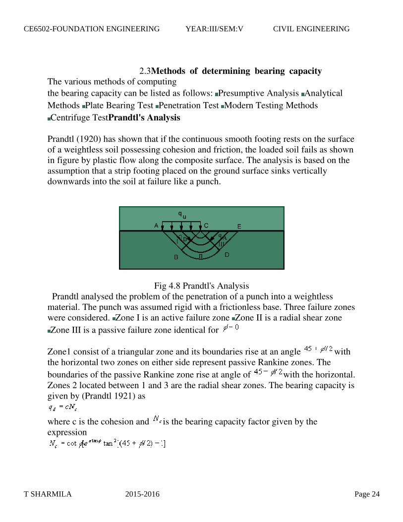
Prandtl (1920) has shown that if the continuous smooth footing rests on the surface of a weightless soil possessing cohesion and friction, the loaded soil fails as shown in figure by plastic flow along the composite surface. The analysis is based on the assumption that a strip footing placed on the ground surface sinks vertically downwards into the soil at failure like a punch.
Fig 4.8 Prandtl's Analysis Prandtl analysed the problem of the penetration of a punch into a weightless material. The punch was assumed rigid with a frictionless base. Three failure zones were considered. Zone I is an active failure zone Zone II is a radial shear zone
Zone III is a passive failure zone identical for
Zone1 consist of a triangular zone and its boundaries rise at an angle with the horizontal two zones on either side represent passive Rankine zones. The
boundaries of the passive Rankine zone rise at angle of with the horizontal. Zones 2 located between 1 and 3 are the radial shear zones. The bearing capacity is given by (Prandtl 1921) as
where c is the cohesion and is the bearing capacity factor given by the expression
2.3Methods of determining bearing capacity The various methods of computing
T SHARMILA 2015-2016 Page 24
CE6502-FOUNDATION ENGINEERING YEAR:III/SEM:V CIVIL ENGINEERING
Reissner (1924) extended Prandtl's analysis for uniform load q per unit area acting on the ground surface. He assumed that the shear pattern is unaltered and gave the bearing capacity expression as follows.
if , the logspiral becomes a circle and Nc is equal to ,also Nq becomes 1. Hence the bearing capacity of such footings becomes
=5.14c+q
if q=0,
we get =2.57qu
where qu is the unconfined compressive strength.
Terzaghi's Bearing Capacity Theory Assumptions in Terzaghi's Bearing Capacity Theory Depth of foundation is less than or equal to its width. Base of the footing is rough. Soil above bottom of foundation has no shear strength; is only a surcharge load against the overturning load Surcharge upto the base of footing is considered. Load applied is vertical and non-eccentric. The soil is homogenous and isotropic. L/B ratio is infinite.
T SHARMILA 2015-2016 Page 25
CE6502-FOUNDATION ENGINEERING YEAR:III/SEM:V CIVIL ENGINEERING

Fig. 4.9 Terzaghi's Bearing Capacity Theory
Consider a footing of width B and depth loaded with Q and resting on a soil of unit weight . The failure of the zones is divided into three zones as shown below. The zone1 represents an active Rankine zone, and the zones 3 are passive zones.the boundaries of the active Rankine zone rise at an angle of , and those of the passive zones at with the horizontal. The zones 2 are known as zones of radial shear, because the lines that constitute one set in the shear pattern in these zones radiate from the outer edge of the base of the footing. Since the base of the footings is rough, the soil located between it and the two surfaces of sliding remains in a state of equilibrium and acts as if it formed part of the footing. The surfaces ad and bd rise at to the horizontal. At the instant of failure, the pressure on each of the surfaces ad and bd is equal to the resultant of the passive earth pressure PP and the cohesion force Ca. since slip occurs along these faces, the resultant earth pressure acts at angle to the normal on each face and as a consequence in a vertical direction. If the weight of the soil adb is disregarded, the equilibrium of the footing requires that
------- (1)
The passive pressure required to produce a slip on def can be divided into two
parts, and . The force represents the resistance due to weight of the mass
T SHARMILA 2015-2016 Page 26
CE6502-FOUNDATION ENGINEERING YEAR:III/SEM:V CIVIL ENGINEERING

adef. The point of application of is located at the lower third point of ad. The
force acts at the midpoint of contact surface ad.
The value of the bearing capacity may be calculated as :
------- (2 )
by introducing into eqn(2) the following values:
Footing subjected to Concentric loading Problem 1 Shallow footing subjected to vertical load along with moment. Design a column footing to carry a vertical load of 40 t (DL+LL) and moment of 1000 Kg-m.
Fig. 4.26 Concentric & Non Concentric Footing
i
2.4.Design of the Column.
T SHARMILA 2015-2016 Page 27
CE6502-FOUNDATION ENGINEERING YEAR:III/SEM:V CIVIL ENGINEERING
Trial 1 Let assume b = 300 mm & D (L) = 400 mm
See chart 33 of SP-16. Assume Diameter of bar 20 mm.
It shows for this trial No Reinforcement required, but practically we have to provide reinforcement.
Trial 2
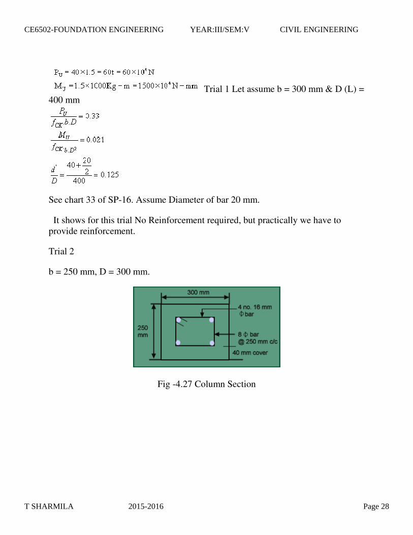
b = 250 mm, D = 300 mm.
Fig -4.27 Column Section
T SHARMILA 2015-2016 Page 28
CE6502-FOUNDATION ENGINEERING YEAR:III/SEM:V CIVIL ENGINEERING

Size of the footing
Fig 4.28 Details of the coulmn
Let D=500mm
For concentric footing;
2.5.Design of footing
T SHARMILA 2015-2016 Page 29
CE6502-FOUNDATION ENGINEERING YEAR:III/SEM:V CIVIL ENGINEERING

V=40 t =40*104 N, e=M/V=1000*104/40*104 =25 mm
For no tension case: Determination of L & B for different values of L & B.
L in m B in m
1.0 2.34 2.0 1.1 2.2 0.988
L=6e=150mm
Let provide footing size is 2.2 m*1.0 m. Check:
= =16.94 t/m2
= =19.92 t/m2
iii Thickness of footing a. Wide beam shear
Factored intensity of soil pressure,
T SHARMILA 2015-2016 Page 30
CE6502-FOUNDATION ENGINEERING YEAR:III/SEM:V CIVIL ENGINEERING

For critical section of wide beam shear: x=(2.2/2)-(0.3/2)-d=0.95-d
Assuming Pt=0.2%, and from table 16 of SP-16
0.0265d2+0.86-0.841=0 By trial and error method, d=0.45 m
T SHARMILA 2015-2016 Page 31
CE6502-FOUNDATION ENGINEERING YEAR:III/SEM:V CIVIL ENGINEERING
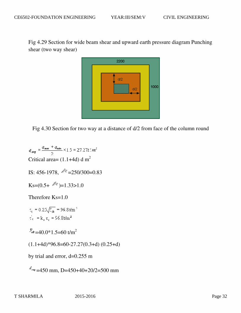
Fig 4.29 Section for wide beam shear and upward earth pressure diagram Punching
shear (two way shear)
Fig 4.30 Section for two way at a distance of d/2 from face of the column round
Critical area= (1.1+4d) d m2
IS: 456-1978, =250/300=0.83
Ks=(0.5+ )=1.33>1.0
Therefore Ks=1.0
=40.0*1.5=60 t/m2
(1.1+4d)*96.8=60-27.27(0.3+d) (0.25+d)
by trial and error, d=0.255 m
=450 mm, D=450+40+20/2=500 mm
T SHARMILA 2015-2016 Page 32
CE6502-FOUNDATION ENGINEERING YEAR:III/SEM:V CIVIL ENGINEERING
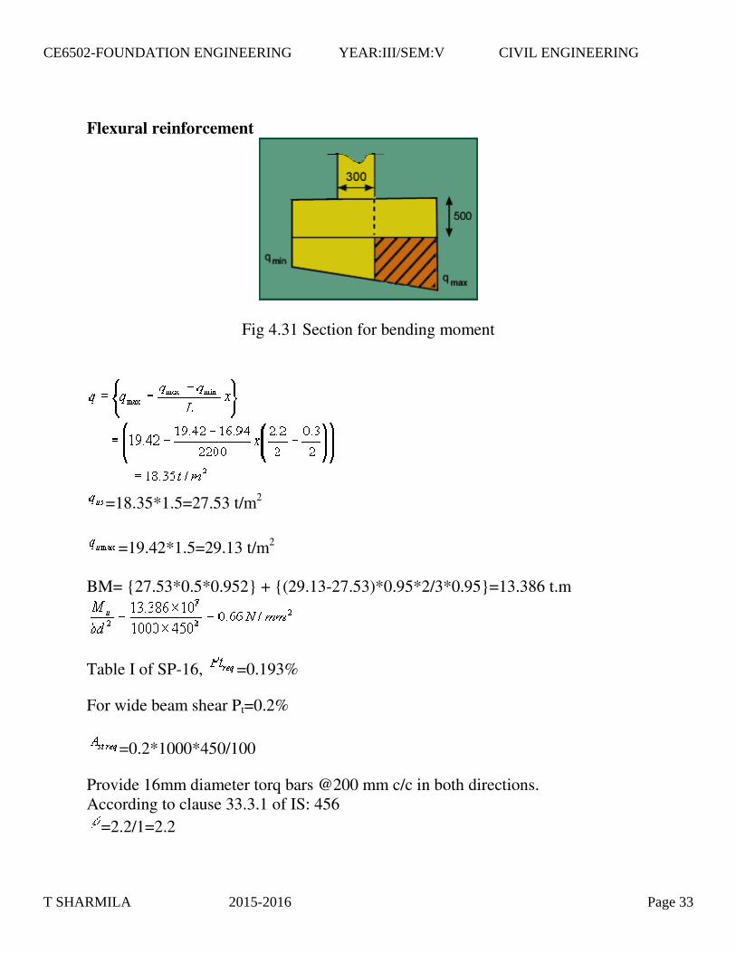
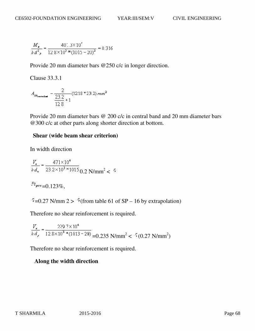
Flexural reinforcement
Fig 4.31 Section for bending moment
=18.35*1.5=27.53 t/m2
=19.42*1.5=29.13 t/m2 BM= {27.53*0.5*0.952} + {(29.13-27.53)*0.95*2/3*0.95}=13.386 t.m
Table I of SP-16, =0.193%
For wide beam shear Pt=0.2%
=0.2*1000*450/100
Provide 16mm diameter torq bars @200 mm c/c in both directions. According to clause 33.3.1 of IS: 456
=2.2/1=2.2
T SHARMILA 2015-2016 Page 33
CE6502-FOUNDATION ENGINEERING YEAR:III/SEM:V CIVIL ENGINEERING

in central band width=2/( +1)* total in short direction=2/(2.2+1)*1980=1237.5 mm2 Hence 16 mm dia @200c/c in longer direction satisfied all criteria & 16 dia @150c/c for central band.
v Check for development length
Clause 25.2.1
Now length of bars provided, (2200-300)/2= 950 mm< Provide extra development length of 1037.5-950=87.5 mm say 90 mm on side of the footing.
vi Transfer of load at base of column
Clause 34.4
Permissible bearing pressure, qb=0.45*15=6.75 =675 t/m2
=1*2.2=2.2 m2
=0.3*0.25=0.075 m2
=675*2.0=1350 t/m2
Footing subjected to eccentric loading Problem 2
T SHARMILA 2015-2016 Page 34
CE6502-FOUNDATION ENGINEERING YEAR:III/SEM:V CIVIL ENGINEERING

Design a non-concentric footing with vertical load =40t and moment = 2tm.
Allowable bearing capacity=20t/m 2 . = 15 N/mm2. =415N/mm
2 .
Determination of size of column:
P = 40t. => = 40 * 1.5 = 60t.
M = 2tm. => = 2 *1.5 = 3tm. Trial I Let us assume footing size b= 250mm, D=350mm.
(see chart for 0.15)
Ref. Chart 33, SP-16 => or, p =0.9%
=
Provide 4 nos. 16 bars as longitudinal reinforcement and 8 stirrups @250mm c/c as transverse reinforcement.
Determination of the size of the footing
Depth of the footing assumed as D= 500mm. For non-concentric footing ,
Area required = Adopt a rectangular footing of size 2m * 1.1m and depth 0.5m.
Eccentricity of footing = M/P= 50mm.
T SHARMILA 2015-2016 Page 35
CE6502-FOUNDATION ENGINEERING YEAR:III/SEM:V CIVIL ENGINEERING
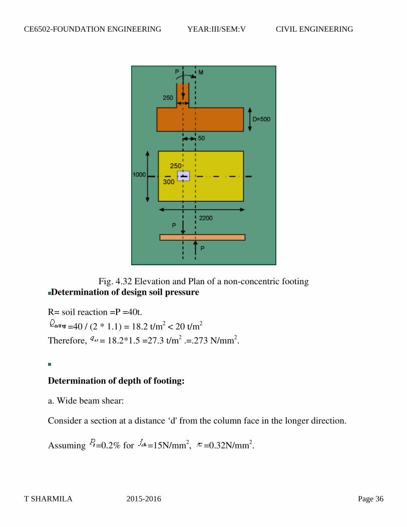
Fig. 4.32 Elevation and Plan of a non-concentric footing Determination of design soil pressure
R= soil reaction =P =40t.
=40 / (2 * 1.1) = 18.2 t/m2 < 20 t/m2
Therefore, = 18.2*1.5 =27.3 t/m2 .=.273 N/mm2.
Determination of depth of footing:
a. Wide beam shear:
Consider a section at a distance ‘d' from the column face in the longer direction.
Assuming =0.2% for =15N/mm2, =0.32N/mm2.
T SHARMILA 2015-2016 Page 36
CE6502-FOUNDATION ENGINEERING YEAR:III/SEM:V CIVIL ENGINEERING

.B.d. = .B.( –d) 0.32 * d = 0.273 * (0.875 – d)
Therefore, d = 0.403 m
b. Punching shear:
Fig. 4.33 Section for wide beam shear
Critical area for punching shear: = 2* ( 350+d+250+d)*d = 4d(300 + d). Clause :31.6.3.1 (IS 456:2000)
= 0.25/0.35 =0.71
= 0.5 + =1.21 >1.0
Therefore, take, =1.0. = 0.25* (15) 0.5 =0.968 N/mm2
' = . =0.968 N/mm2 96.8 * 4d* (0.3 +d) = 60 – 27.3 *(0.35+d)8(0.25+d) d = 0.246m.
T SHARMILA 2015-2016 Page 37
CE6502-FOUNDATION ENGINEERING YEAR:III/SEM:V CIVIL ENGINEERING
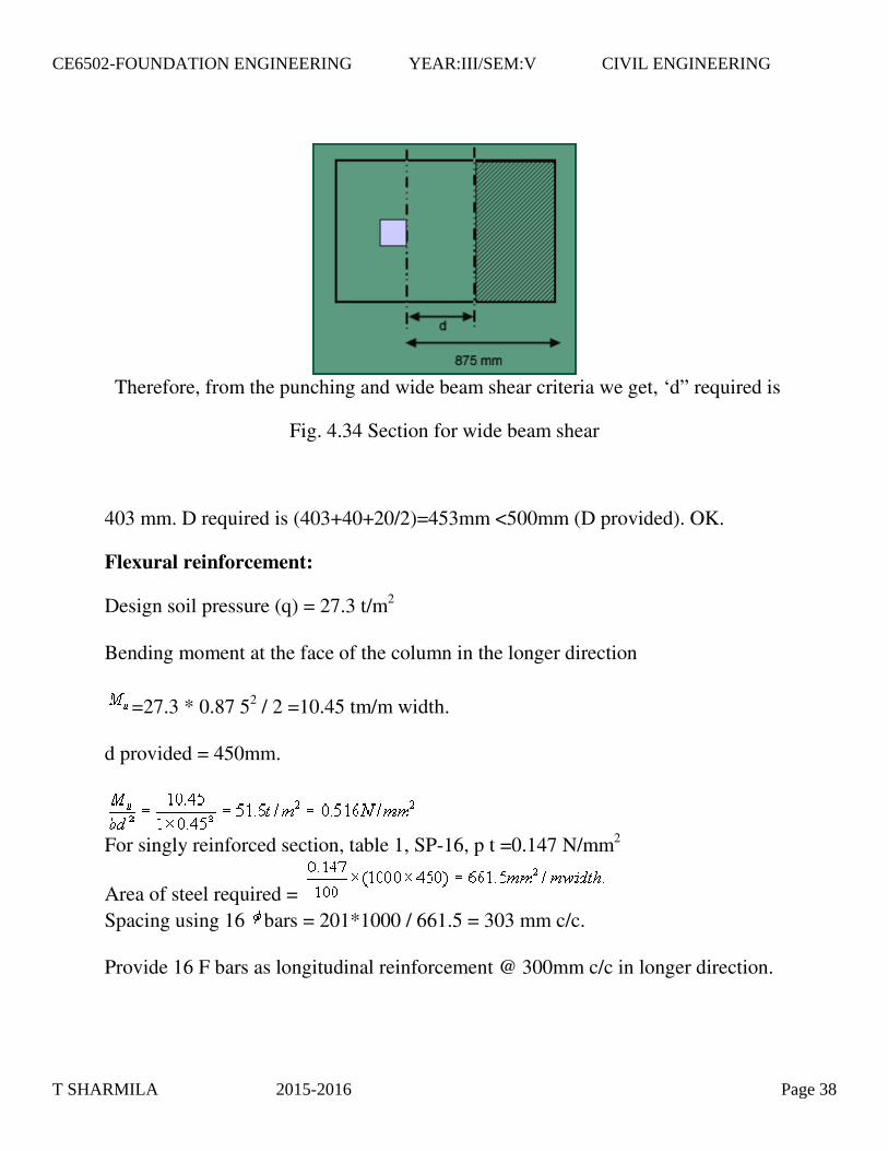
Therefore, from the punching and wide beam shear criteria we get, ‘d” required is
Fig. 4.34 Section for wide beam shear
403 mm. D required is (403+40+20/2)=453mm <500mm (D provided). OK.
Flexural reinforcement:
Design soil pressure (q) = 27.3 t/m2 Bending moment at the face of the column in the longer direction
=27.3 * 0.87 52 / 2 =10.45 tm/m width. d provided = 450mm.
For singly reinforced section, table 1, SP-16, p t =0.147 N/mm2
Area of steel required = Spacing using 16 bars = 201*1000 / 661.5 = 303 mm c/c. Provide 16 F bars as longitudinal reinforcement @ 300mm c/c in longer direction.
T SHARMILA 2015-2016 Page 38
CE6502-FOUNDATION ENGINEERING YEAR:III/SEM:V CIVIL ENGINEERING

Cl. 33.4.1. (IS-456:2000) B = 2.0 / 1.1 =1.82 Area of steel in the longer direction = 661.5 * 2 =1323 mm2 Area of steel in the central band =2 / (1.82 +1)* 1323 =938 mm2 Spacing = 207.6 mm.
Provide 16 bars as longitudinal reinforcement @ 200mm c/c in shorter direction in the central band. For remaining portion provide spacing @330mm c/c.
The central band width = width of the foundation =1100mm.
Check for development length:
Cl. 26.2.1 (IS 456 :2000)
Now, length of bars provided =(2000 – 350)/2 = 825 mm.< . Extra length to be provided = (1037.5 – 825) = 212.5mm. Provide development length equal to 225mm at the ends.
Transfer of load at the column footing junction :
Cl. 33.4 (IS 456:2000)
Assuming 2:1 load dispersion,
Required L = {350 + 2*500*2} =2350mm >2000mm.
T SHARMILA 2015-2016 Page 39
CE6502-FOUNDATION ENGINEERING YEAR:III/SEM:V CIVIL ENGINEERING

Required B = {250 + 2*500*2} =2250mm >1100mm.
= 2 * 1.1 =2.2 m2.
= 0.25 * 0.35 = 0.0875 m2
Ö ( / ) = 5.01 > 2.0. Take as 2.0.
. = q b * Ö (A 1 / A 2 ) = 675 * 2 = 1350 t/m2 .
= 40*1.5/(0.25* 0.35) * { 1 + 6 *0.05 / 0.35 } = 1273 t/m2 . < 1350 t/m2 .
Therefore, the junction is safe.
Actually there is no need to extend column bars inside the footing, but as a standard practice the column bars are extended upto a certain distance inside the footing.
Design of strap footing: Example:
The column positions are is as shown in fig. 4.35. As column one is very close to the boundary line, we have to provide a strip footing for both footings.
Fig. 4.35 Strap footing Design of the column Column A:
T SHARMILA 2015-2016 Page 40
CE6502-FOUNDATION ENGINEERING YEAR:III/SEM:V CIVIL ENGINEERING
=750 KN
Let = 0.8%, so, Ax= 0.008A and Ac = 0.992A, Where, A is the gross area of concrete. As per clause 39.3 of IS 456-2000, 750 x 103 = (0.4 x 15 x 0.992A) + (0.67 x 415 x 0.008A) A = 91727.4 mm2 Provide column size (300 x 300) mm
750 x 103 = 0.4 x 15 x (1- (pt/100)) x 90000 + 0.67 x 415x ( /100) x 90000
= 0.86% ,
= (0.86/100) x (300)2 = 774 mm2 Provide 4 no's tor 16 as longitudinal reinforcement with tor 8 @ 250 c/c lateral ties.
Column B:
=1500 KN Provide column size (400 x 400) mm
1500 x 103 = 0.4 x 15 x (1- ( /100)) x 160000 + 0.67 x 415x (pt/100) x 160000
= 1.24% , = (1.24/100) x (300)2 = 1985 mm2 Provide 8 no.s tor 16 as longitudinal reinforcement with tor 8 @ 250 c/c lateral ties.
Footing design
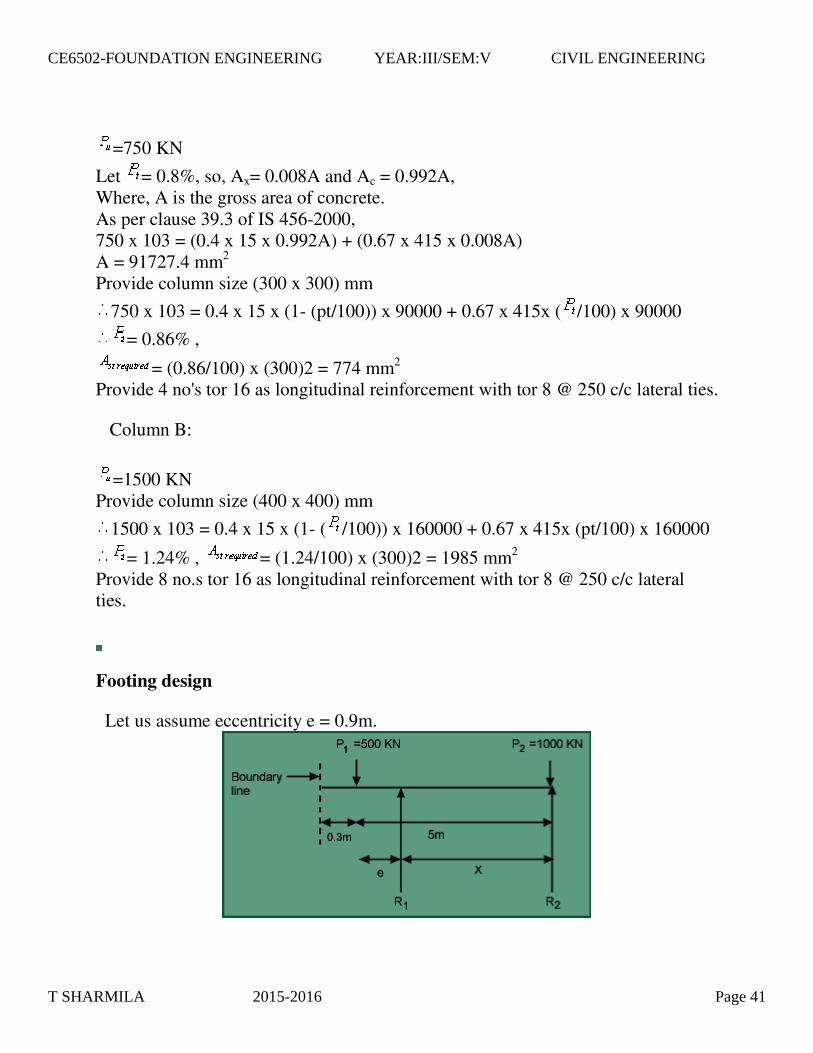
Let us assume eccentricity e = 0.9m.
T SHARMILA 2015-2016 Page 41
CE6502-FOUNDATION ENGINEERING YEAR:III/SEM:V CIVIL ENGINEERING

Fig. 4.36 Strap footing – soil reaction
Taking moment about line ,
x 5 – x (5-e) = 0
Footing size:
Fig. 4.37 Footing sizes For footing A:
= 2(0.9+0.3) =2.4m. Assume overall thickness of footing, D = 600mm.
For footing B:
Assume square footing of size ,
=
T SHARMILA 2015-2016 Page 42
CE6502-FOUNDATION ENGINEERING YEAR:III/SEM:V CIVIL ENGINEERING
= 2.13m Provide (2.2 x 2.2)m footing.
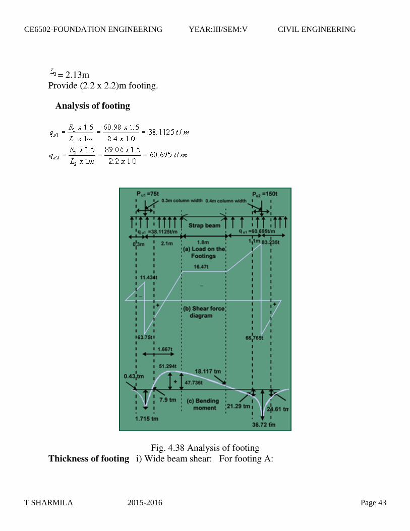
Analysis of footing
Fig. 4.38 Analysis of footing Thickness of footing i) Wide beam shear: For footing A:
T SHARMILA 2015-2016 Page 43
CE6502-FOUNDATION ENGINEERING YEAR:III/SEM:V CIVIL ENGINEERING
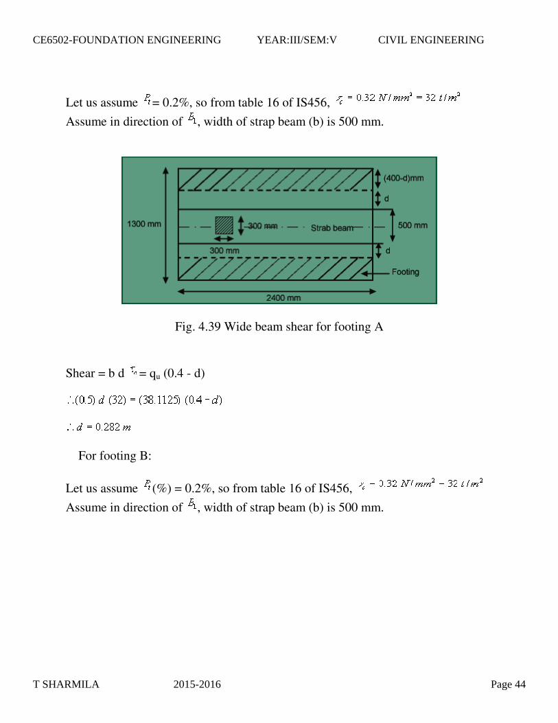
Let us assume = 0.2%, so from table 16 of IS456,
Assume in direction of , width of strap beam (b) is 500 mm.
Fig. 4.39 Wide beam shear for footing A
Shear = b d = qu (0.4 - d)
For footing B:
Let us assume (%) = 0.2%, so from table 16 of IS456,
Assume in direction of , width of strap beam (b) is 500 mm.
T SHARMILA 2015-2016 Page 44
CE6502-FOUNDATION ENGINEERING YEAR:III/SEM:V CIVIL ENGINEERING

Fig. 4.40 Wide beam shear for footing B
Shear = b d = qu (0.4 - d)
> 600 mm depth earlier assumed.
Increasing the width of the beam to 700 mm
Fig. 4.41 Wide beam shear for footing B
Let us assume (%) = 0.3%, so from table 16 of IS456,
T SHARMILA 2015-2016 Page 45
CE6502-FOUNDATION ENGINEERING YEAR:III/SEM:V CIVIL ENGINEERING
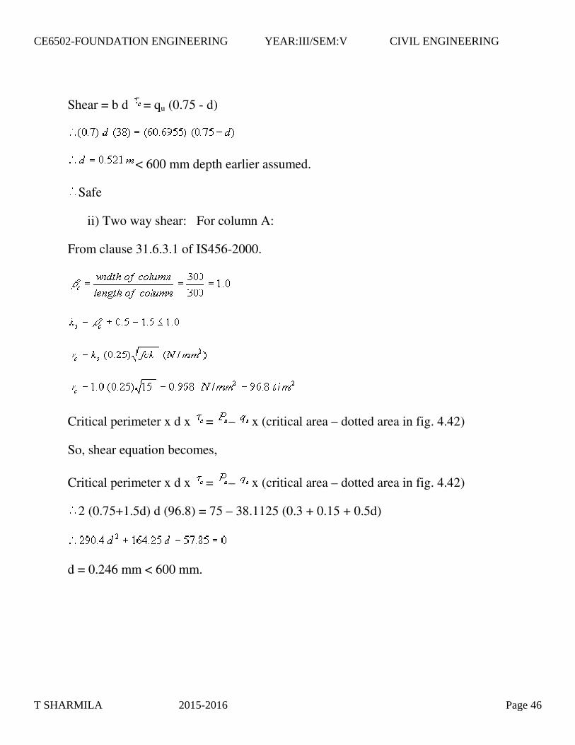
Shear = b d = qu (0.75 - d)
< 600 mm depth earlier assumed.
Safe
ii) Two way shear: For column A:
From clause 31.6.3.1 of IS456-2000.
Critical perimeter x d x = – x (critical area – dotted area in fig. 4.42)
So, shear equation becomes,
Critical perimeter x d x = – x (critical area – dotted area in fig. 4.42)
2 (0.75+1.5d) d (96.8) = 75 – 38.1125 (0.3 + 0.15 + 0.5d)
d = 0.246 mm < 600 mm.
T SHARMILA 2015-2016 Page 46
CE6502-FOUNDATION ENGINEERING YEAR:III/SEM:V CIVIL ENGINEERING

Fig. 4.42 Wide beam shear for footing A
For column B: From clause 31.6.3.1 of IS456-2000.
Critical perimeter = 2 (0.4+d+0.4+d) = 4 (0.4+d) So, shear equation becomes,
Critical perimeter x d x = – x (critical area – dotted area in fig. 4.43) 2 (0.4+d) d (96.8) = 150 – 60.6955 (0.4 + d)
d = 0.355 mm < 600 mm. Among all the required d values (for wide beam shear and two way shear criteria),
Max. = 521 mm.
= 521 + (20/2) + 40 = 571 mm So, provide D = 600 mm
= 550 mm
Reinforcement for flexure for footings (i) Design along the length direction: Comparing the moments at the column faces in both the footings (A & B),
= 24.61 tm (for Footing B)
T SHARMILA 2015-2016 Page 47
CE6502-FOUNDATION ENGINEERING YEAR:III/SEM:V CIVIL ENGINEERING
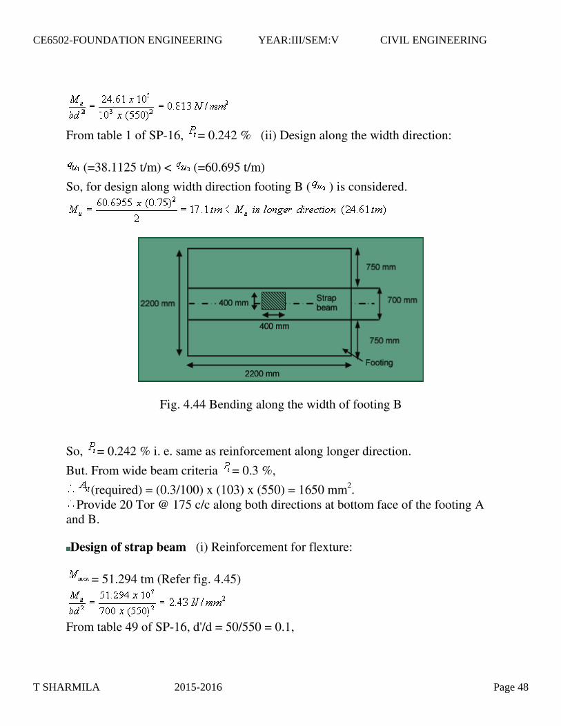
From table 1 of SP-16, = 0.242 % (ii) Design along the width direction:
(=38.1125 t/m) < (=60.695 t/m)
So, for design along width direction footing B ( ) is considered.
Fig. 4.44 Bending along the width of footing B
So, = 0.242 % i. e. same as reinforcement along longer direction.
But. From wide beam criteria = 0.3 %,
(required) = (0.3/100) x (103) x (550) = 1650 mm2. Provide 20 Tor @ 175 c/c along both directions at bottom face of the footing A
and B.
Design of strap beam (i) Reinforcement for flexture:
= 51.294 tm (Refer fig. 4.45)
From table 49 of SP-16, d'/d = 50/550 = 0.1,
T SHARMILA 2015-2016 Page 48
CE6502-FOUNDATION ENGINEERING YEAR:III/SEM:V CIVIL ENGINEERING

= 0.83 % and Pc= 0.12 %
(required on tension face) = (0.83/100) x 700 x 550 = 3195.5 mm2,
(required on compression face) = (0.12/100) x 700 x 550 = 462 mm2, Provide (6+5=) 11 no.s Tor 20 at top of the strap beam and 4 no.s Tor 20 at
bottom of the strap beam.
(ii) Check for shear:
Vmax = 83.235 t
< max = 2.5 N/mm2 (for M15)
(provided) = From table 61 of SP-16, = 0.57 N/mm2 But, provide shear reinforcement for shear = ( acting – ) = 1.592 N/mm2= Vus
= 11.144 KN/cm From table 16 of SP-16, using 4L stirrups, (Vus/d) = (11.144/2) = 5.572 KN/cm
From table 62 of SP-16, provide 4L-stirrups 10 Tor @ 100 c/c near the column (upto distance of d=550mm from column face) and 4L-stirrups 10 Tor @ 250 c/c for other portions.
Check for development length
From clause 25.2.1 of IS456-2000,
Development length = =
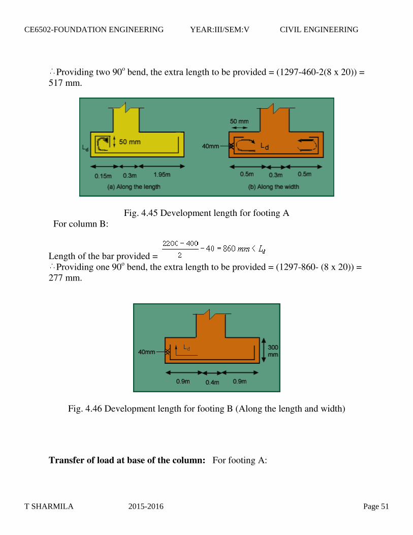
For column A:
Length of the bar provided = 150-40 = 110mm < By providing 2 no.s 90o bend the extra length to be provided = (1297-110-3(8 x
20)) = 707 mm.
T SHARMILA 2015-2016 Page 49
CE6502-FOUNDATION ENGINEERING YEAR:III/SEM:V CIVIL ENGINEERING

In B direction length of the bar provided = Providing two 90o bend, the extra length to be provided = (1297-460-2(8 x 20)) =
517 mm.
(ii) Check for shear:
Vmax = 83.235 t
< max = 2.5 N/mm2 (for M15)
(provided) = From table 61 of SP-16, = 0.57 N/mm2 But, provide shear reinforcement for shear = ( acting – ) = 1.592 N/mm2= Vus
= 11.144 KN/cm From table 16 of SP-16, using 4L stirrups, (Vus/d) = (11.144/2) = 5.572 KN/cm
From table 62 of SP-16, provide 4L-stirrups 10 Tor @ 100 c/c near the column (upto distance of d=550mm from column face) and 4L-stirrups 10 Tor @ 250 c/c for other portions.
Check for development length
From clause 25.2.1 of IS456-2000,
Development length = =
For column A:
Length of the bar provided = 150-40 = 110mm < By providing 2 no.s 90o bend the extra length to be provided = (1297-110-3(8 x
20)) = 707 mm.
In B direction length of the bar provided =
T SHARMILA 2015-2016 Page 50
CE6502-FOUNDATION ENGINEERING YEAR:III/SEM:V CIVIL ENGINEERING
Providing two 90o bend, the extra length to be provided = (1297-460-2(8 x 20)) = 517 mm.
Fig. 4.45 Development length for footing A For column B:
Length of the bar provided = Providing one 90o bend, the extra length to be provided = (1297-860- (8 x 20)) =
277 mm.
Fig. 4.46 Development length for footing B (Along the length and width)
Transfer of load at base of the column: For footing A:
T SHARMILA 2015-2016 Page 51
CE6502-FOUNDATION ENGINEERING YEAR:III/SEM:V CIVIL ENGINEERING
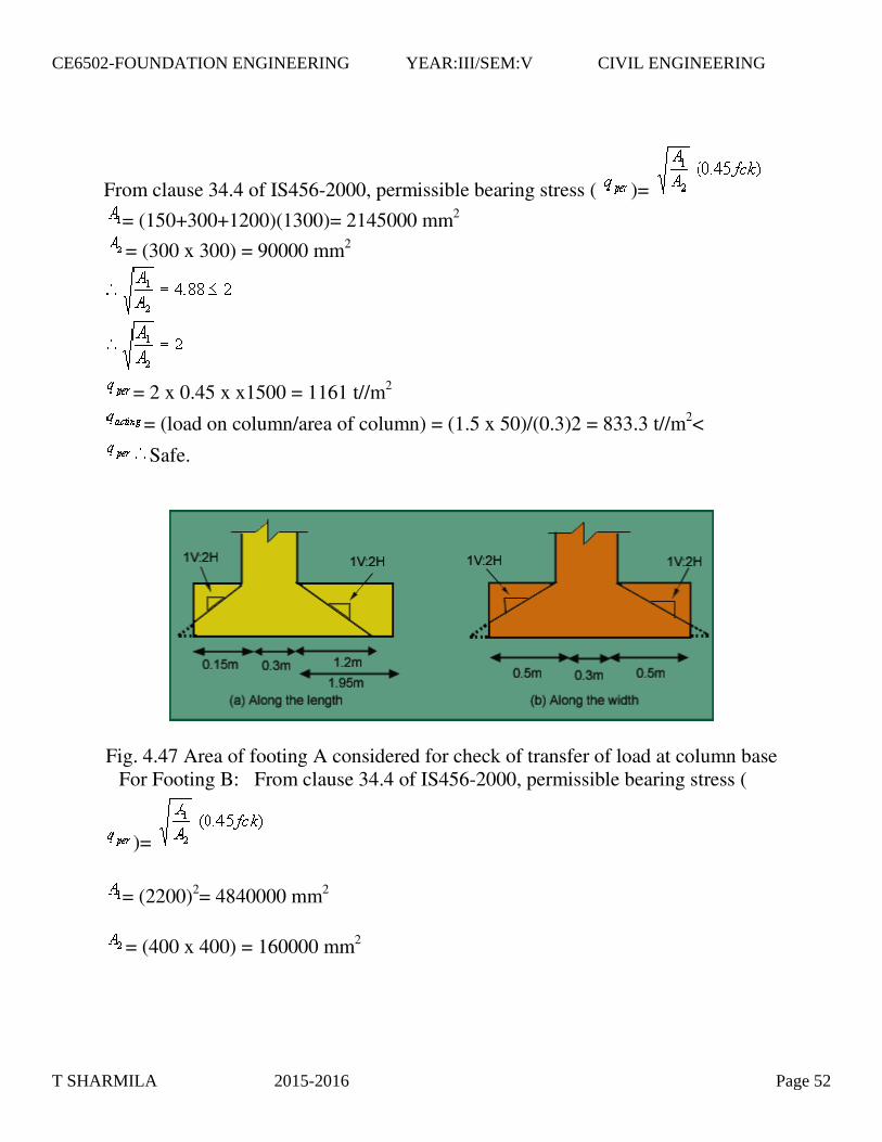
From clause 34.4 of IS456-2000, permissible bearing stress ( )=
= (150+300+1200)(1300)= 2145000 mm2
= (300 x 300) = 90000 mm2
= 2 x 0.45 x x1500 = 1161 t//m2
= (load on column/area of column) = (1.5 x 50)/(0.3)2 = 833.3 t//m2<
Safe.
Fig. 4.47 Area of footing A considered for check of transfer of load at column base For Footing B: From clause 34.4 of IS456-2000, permissible bearing stress (
)=
= (2200)2= 4840000 mm2
= (400 x 400) = 160000 mm2
T SHARMILA 2015-2016 Page 52
CE6502-FOUNDATION ENGINEERING YEAR:III/SEM:V CIVIL ENGINEERING
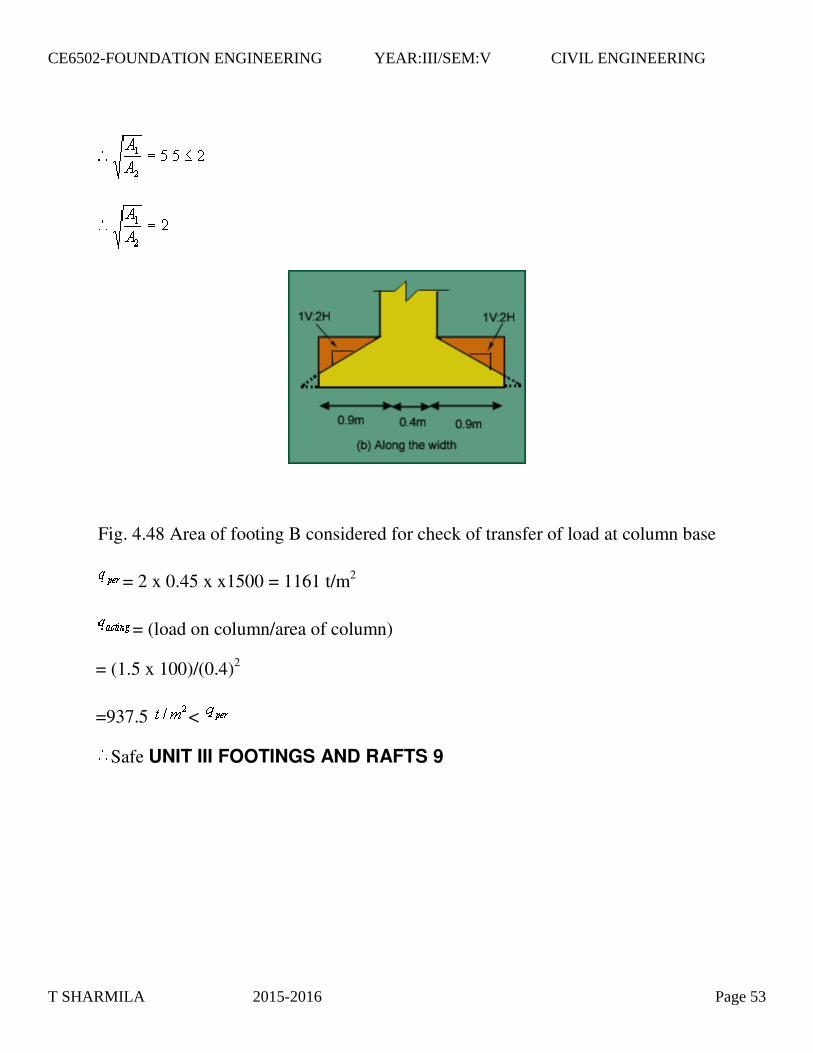
Fig. 4.48 Area of footing B considered for check of transfer of load at column base
= 2 x 0.45 x x1500 = 1161 t/m2
= (load on column/area of column)
= (1.5 x 100)/(0.4)2
=937.5 <
Safe UNIT III FOOTINGS AND RAFTS 9
T SHARMILA 2015-2016 Page 53
CE6502-FOUNDATION ENGINEERING YEAR:III/SEM:V CIVIL ENGINEERING
T SHARMILA 2015-2016 Page 54
CE6502-FOUNDATION ENGINEERING YEAR:III/SEM:V CIVIL ENGINEERING

=800kN
=1000kN
=20 t/m2,M15, =415kN/m2
Fig. 4.51 Loading on combined footing
Column size: 400x400mm. See Fig 4.54 for details of footing. Column design
Let pt=0.8%
=.008A; =0.992A
Clause.39.3 of IS 456-2000
A=146763.8mm2
=1174.11 mm2, =145589.746mm2
Design of
3.1.Combined Footing
T SHARMILA 2015-2016 Page 55
CE6502-FOUNDATION ENGINEERING YEAR:III/SEM:V CIVIL ENGINEERING

Provide footing of 400x400size for both columns.
Using 8-16 as main reinforcement and 8 @250c/c as lateral tie
Design of Footing
Fig. 4.52 Forces acting on the footing Resultant of Column Load
R =1800 kN acting 3.08m from the boundary.
Area of the footing :
Taking length L=6m, Depth of footing =0.9m, ,
Width of footing, =1.549m.
Therefore, provide footing of dimension 6m x 1.6m
Soil Pressure q = =18.75 t/m2< 20 t/m2 OK.
=28.125 t/m2
Soil pressure intensity acting along the length =B x =1.6x28.125 =45t/m.
RB =119.88kN, RC =150.12kN.
T SHARMILA 2015-2016 Page 56
CE6502-FOUNDATION ENGINEERING YEAR:III/SEM:V CIVIL ENGINEERING
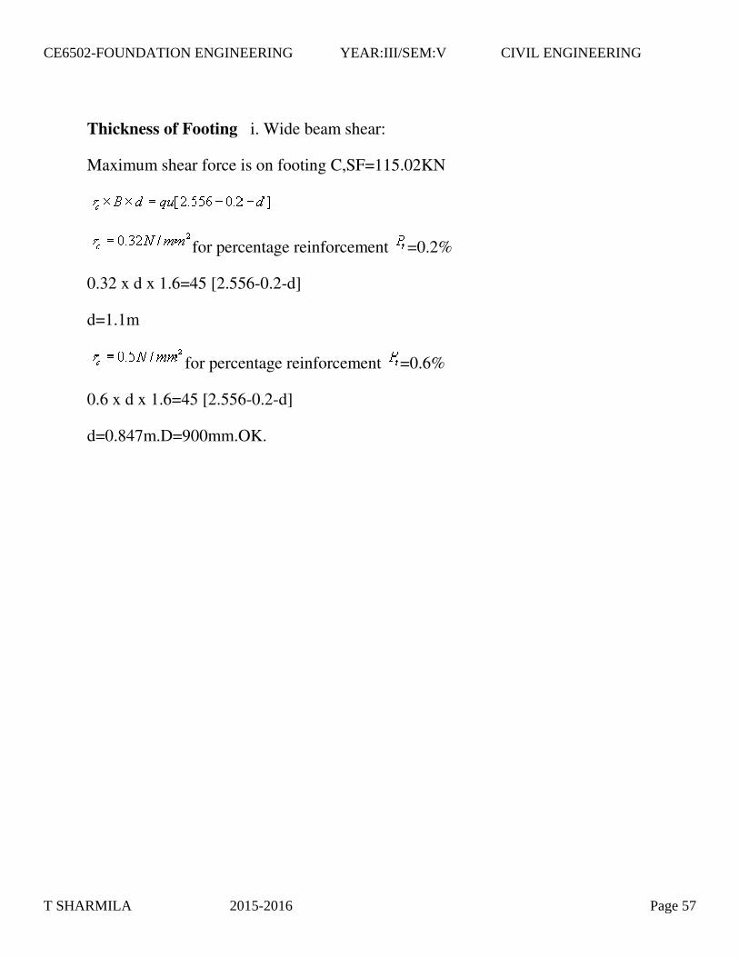
Thickness of Footing i. Wide beam shear:
Maximum shear force is on footing C,SF=115.02KN
for percentage reinforcement =0.2%
0.32 x d x 1.6=45 [2.556-0.2-d]
d=1.1m
for percentage reinforcement =0.6%
0.6 x d x 1.6=45 [2.556-0.2-d]
d=0.847m.D=900mm.OK.
T SHARMILA 2015-2016 Page 57
CE6502-FOUNDATION ENGINEERING YEAR:III/SEM:V CIVIL ENGINEERING

ii.Two way Shear Thickness of
Footing i. Wide beam shear:
Maximum shear force is on footing C,SF=115.02KN
for percentage reinforcement =0.2%
0.32 x d x 1.6=45 [2.556-0.2-d]
d=1.1m
for percentage reinforcement =0.6%
0.6 x d x 1.6=45 [2.556-0.2-d]
T SHARMILA 2015-2016 Page 58
CE6502-FOUNDATION ENGINEERING YEAR:III/SEM:V CIVIL ENGINEERING

d=0.847m.D=900mm.OK.
ii.Two way Shear
Column B
d=0.415m. Column A 2d[(0.4+d)+(0.42+d/2)] x 96.8=120-28.125[(0.4+d)(0.42+d/2)] d=0.3906m
=0.85mm
=900mm, =850mm.OK.
Flexural reinforcement
Along Length Direction
=1.15N/mm2 Table 1of SP16
=0.354%
provided=0.6%
required=5100 mm2/mm
Provide 28 @120mmc/c at top and bottom of the footing Along width direction
T SHARMILA 2015-2016 Page 59
CE6502-FOUNDATION ENGINEERING YEAR:III/SEM:V CIVIL ENGINEERING
T SHARMILA 2015-2016 Page 60
CE6502-FOUNDATION ENGINEERING YEAR:III/SEM:V CIVIL ENGINEERING

Raft Footing Design the
raft footing for the given loads on the columns and spacing between the columns as
shown below.
T SHARMILA 2015-2016 Page 61
CE6502-FOUNDATION ENGINEERING YEAR:III/SEM:V CIVIL ENGINEERING

Fig 4.57 column locations and intensity of loads acting on the raft a) Column sizes
Take size of the columns are as: 300*450 mm for load of less than 115 ton 450*450 mm for a load of greater than 115 ton
Thickness of raft
Two way shear The shear should be checked for every column, but in this case because of symmetry property checking for 115 t, 150 t, and 55 t is enough.
For 150 t column
T SHARMILA 2015-2016 Page 62
CE6502-FOUNDATION ENGINEERING YEAR:III/SEM:V CIVIL ENGINEERING
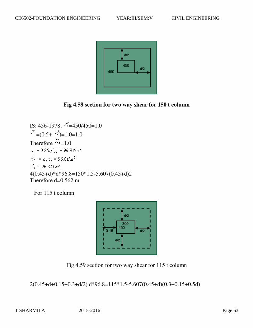
Fig 4.58 section for two way shear for 150 t column
IS: 456-1978, =450/450=1.0
=(0.5+ )=1.0=1.0
Therefore =1.0
4(0.45+d)*d*96.8=150*1.5-5.607(0.45+d)2 Therefore d=0.562 m
For 115 t column
Fig 4.59 section for two way shear for 115 t column
2(0.45+d+0.15+0.3+d/2) d*96.8=115*1.5-5.607(0.45+d)(0.3+0.15+0.5d)
T SHARMILA 2015-2016 Page 63
CE6502-FOUNDATION ENGINEERING YEAR:III/SEM:V CIVIL ENGINEERING

Therefore d=0.519 m
For 55 t column
Fig 4.60 section for two way shear for 55 t column
2(0.45+0.075+0.5d+0.15+0.3+0.5d) d*96.8=55*1.5-5.607(0.45+0.5d+0.075)(0.3+0.5d+0.15)
Therefore d=0.32 m
The guiding thickness is 0.562m and code says that the minimum thickness should not be less than 1.0m.
let provide a overall depth of 1.1m=D
=1100-75-20/2=1015mm.
To calculate k & -Stiffness factors
There are two criterions for checking the rigidity of the footing: Plate size used is 300*300 mm. For clays: =0.5,
Take k=0.7 and B=30 cm Es=15.75 kg/cm2=1.575 N/mm2
T SHARMILA 2015-2016 Page 64
CE6502-FOUNDATION ENGINEERING YEAR:III/SEM:V CIVIL ENGINEERING
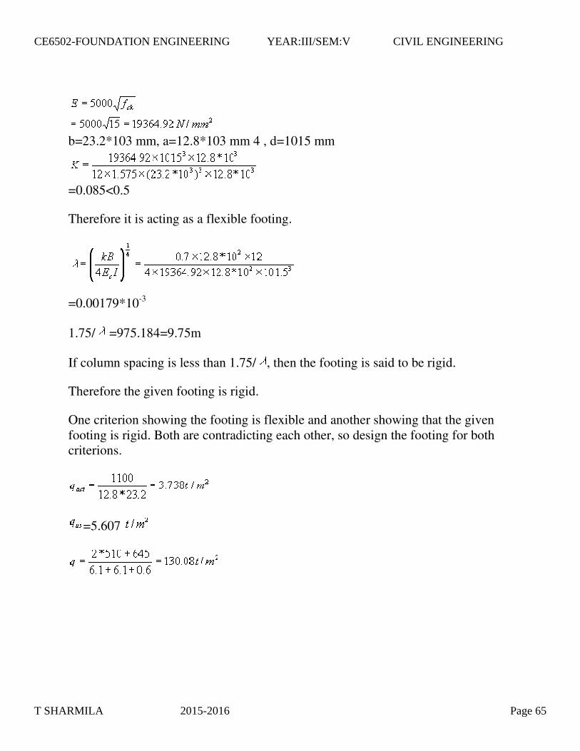
b=23.2*103 mm, a=12.8*103 mm 4 , d=1015 mm
=0.085<0.5
Therefore it is acting as a flexible footing.
=0.00179*10-3
1.75/ =975.184=9.75m
If column spacing is less than 1.75/ , then the footing is said to be rigid.
Therefore the given footing is rigid.
One criterion showing the footing is flexible and another showing that the given footing is rigid. Both are contradicting each other, so design the footing for both criterions.
=5.607
T SHARMILA 2015-2016 Page 65
CE6502-FOUNDATION ENGINEERING YEAR:III/SEM:V CIVIL ENGINEERING
T SHARMILA 2015-2016 Page 66
CE6502-FOUNDATION ENGINEERING YEAR:III/SEM:V CIVIL ENGINEERING
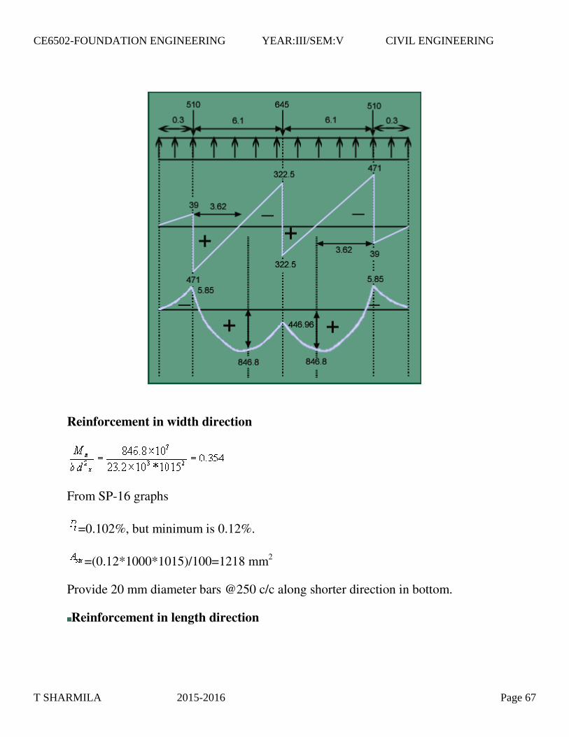
Reinforcement in width direction
From SP-16 graphs
=0.102%, but minimum is 0.12%.
=(0.12*1000*1015)/100=1218 mm2
Provide 20 mm diameter bars @250 c/c along shorter direction in bottom.
Reinforcement in length direction
T SHARMILA 2015-2016 Page 67
CE6502-FOUNDATION ENGINEERING YEAR:III/SEM:V CIVIL ENGINEERING
Provide 20 mm diameter bars @250 c/c in longer direction.
Clause 33.3.1
Provide 20 mm diameter bars @ 200 c/c in central band and 20 mm diameter bars @300 c/c at other parts along shorter direction at bottom.
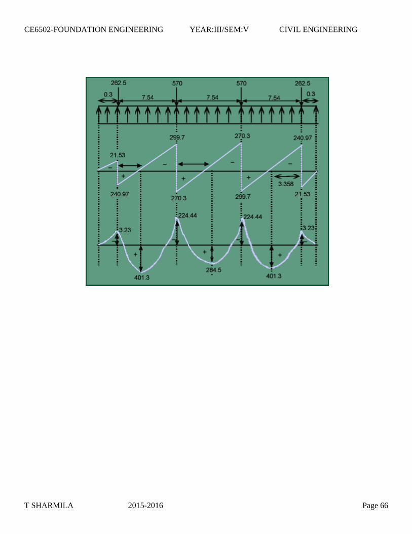
Shear (wide beam shear criterion)
In width direction
0.2 N/mm2 <
=0.123%,
=0.27 N/mm 2 > (from table 61 of SP – 16 by extrapolation)
Therefore no shear reinforcement is required.
=0.235 N/mm2 < (0.27 N/mm2)
Therefore no shear reinforcement is required.
Along the width direction
T SHARMILA 2015-2016 Page 68
CE6502-FOUNDATION ENGINEERING YEAR:III/SEM:V CIVIL ENGINEERING
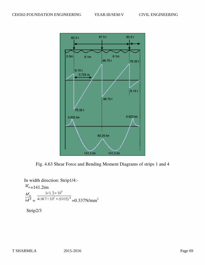
Fig. 4.63 Shear Force and Bending Moment Diagrams of strips 1 and 4
In width direction: Strip1/4:-
=141.2tm
= =0.337N/mm2
Strip2/3
T SHARMILA 2015-2016 Page 69
CE6502-FOUNDATION ENGINEERING YEAR:III/SEM:V CIVIL ENGINEERING

Fig. 4.64 Shear Force and Bending Moment Diagrams of strips 2 and 3 Strip 2/3
=282.36tm
= =0.364N/mm2
Minimum =0.12%has to be provided.
Provide 20 @200c/c in centre band and 20 @300c/c at other parts along the shorter direction.
T SHARMILA 2015-2016 Page 70
CE6502-FOUNDATION ENGINEERING YEAR:III/SEM:V CIVIL ENGINEERING
1. Shear check
Along width direction:-
For strip1/4:
=76.35t
= =0.185N/mm2< , OK.
For strip 2/3:
=159.14 t
= =0.208N/mm2< , OK.
Hence no shear reinforcement is required.
Development Length
= =1128.3mm At the ends, length of bar provided=150mm. Extra length to be provided=1128.3-150-8x20=818.3mm. Provide a Development length of 850mm
3. Transfer of load at the base of the column:-
For end column;
=2650X2725=7.22125x106mm2
=300x450=135000mm2
7.31 But not greater than 2.0
T SHARMILA 2015-2016 Page 71
CE6502-FOUNDATION ENGINEERING YEAR:III/SEM:V CIVIL ENGINEERING
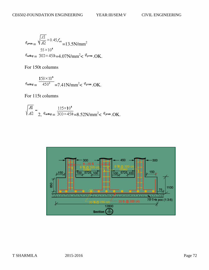
= =13.5N/mm2
= =4.07N/mm2< .OK. For 150t columns
= =7.41N/mm2< .OK. For 115t columns
2, = =8.52N/mm2< .OK.
T SHARMILA 2015-2016 Page 72
CE6502-FOUNDATION ENGINEERING YEAR:III/SEM:V CIVIL ENGINEERING

www.Vidyarthiplus.com
T SHARMILA 2015-2016 Page 73
CE6502-FOUNDATION ENGINEERING YEAR:III/SEM:V CIVIL ENGINEERING

UNIT IV PILES 9
Potential increased of shaft capacities is undesirable if negative friction is to be
feared. (Negative friction is also called drag down force) High displacement piles
are undesirable in stiff cohesive soils, otherwise excessive heaving takes place.
Compaction piles.( Used for ground movement, not for load bearing ) Tension
piles/Anchored piles.(To resist upliftment) Butter piles (Inclined) --- +ve and –ve.
Encountered with high artesian pressures on cased piles should be excluded.
(Mainly for bridges and underwater construction) Driven piles are undesirable due
to noise, damage caused by vibration, ground heaving. Heavy structures with
large reactions require high capacity piles and small diameter cast-in-situ piles are
inadequate. 4.4PILE CLASSIFICATION Friction piles. End bearing piles.
FOUNDATIONS Generally for structures with load >10 , we go for deep
foundations. Deep foundations are used in the following cases: Huge vertical load
with respect to soil capacity. Very weak soil or problematic soil. Huge lateral
loads eg. Tower, chimneys. Scour depth criteria. For fills having very large
depth. Uplift situations (expansive zones) Urban areas for future large and huge
construction near the existing building. 4.2CLASSIFICATION OF PILES 1.
Based on material Timber piles Steel piles Concrete piles Composite piles (steel
+ concrete) 2. Based on method of installation Driven piles ----(i) precast (ii) cast-
in-situ. Bored piles. 3. Based on the degree of disturbance Large displacement
piles (occurs for driven piles) Small displacement piles (occurs for bored piles)
4.3.POINTS TO BE CONSIDERED FOR CHOOSING PILES Loose cohesion
less soil develops much greater shaft bearing capacities if driven large
displacement piles are used. Displacement effect enhanced by tapered shafts.
4.1.DESIGN METHODOLOGY FOR PILES The detailed design methodology of piles is described in the following sections. REQUIREMENT
FOR DEEP
T SHARMILA 2015-2016 Page 74
CE6502-FOUNDATION ENGINEERING YEAR:III/SEM:V CIVIL ENGINEERING
www.Vidyarthiplus.com
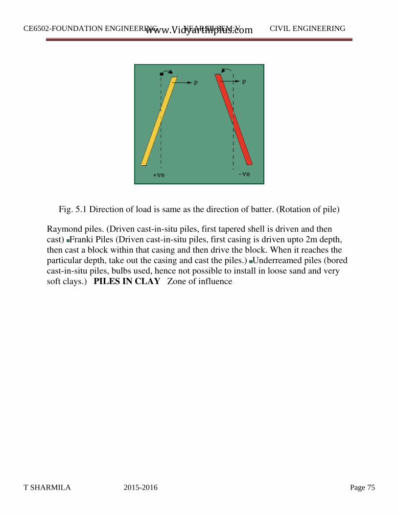
Fig. 5.1 Direction of load is same as the direction of batter. (Rotation of pile)
Raymond piles. (Driven cast-in-situ piles, first tapered shell is driven and then cast) Franki Piles (Driven cast-in-situ piles, first casing is driven upto 2m depth, then cast a block within that casing and then drive the block. When it reaches the particular depth, take out the casing and cast the piles.) Underreamed piles (bored cast-in-situ piles, bulbs used, hence not possible to install in loose sand and very soft clays.) PILES IN CLAY Zone of influence
T SHARMILA 2015-2016 Page 75
CE6502-FOUNDATION ENGINEERING YEAR:III/SEM:V CIVIL ENGINEERING
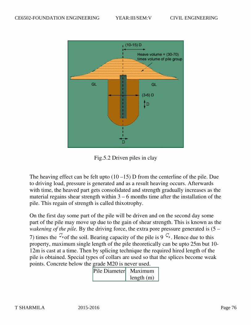
Fig.5.2 Driven piles in clay
The heaving effect can be felt upto (10 –15) D from the centerline of the pile. Due to driving load, pressure is generated and as a result heaving occurs. Afterwards with time, the heaved part gets consolidated and strength gradually increases as the material regains shear strength within 3 – 6 months time after the installation of the pile. This regain of strength is called thixotrophy.
On the first day some part of the pile will be driven and on the second day some part of the pile may move up due to the gain of shear strength. This is known as the wakening of the pile. By the driving force, the extra pore pressure generated is (5 –
7) times the of the soil. Bearing capacity of the pile is 9 . Hence due to this property, maximum single length of the pile theoretically can be upto 25m but 10-12m is cast at a time. Then by splicing technique the required hired length of the pile is obtained. Special types of collars are used so that the splices become weak points. Concrete below the grade M20 is never used.
Pile Diameter Maximum length (m) à
T SHARMILA 2015-2016 Page 76
CE6502-FOUNDATION ENGINEERING YEAR:III/SEM:V CIVIL ENGINEERING

250 12 300 15 350 18 400 21 450 25
Fig.5.3 Generation of
T SHARMILA 2015-2016 Page 77
CE6502-FOUNDATION ENGINEERING YEAR:III/SEM:V CIVIL ENGINEERING

Fig.5.4a Driven piles in loose sand
4.4.PILES IN SAND
T SHARMILA 2015-2016 Page 78
CE6502-FOUNDATION ENGINEERING YEAR:III/SEM:V CIVIL ENGINEERING

Fig.5.4b Improvement in f due to pile driving
Fig.5.5 Settlement of pile groups
CODAL PROVISION SAFE LOAD ON PILES/PILE GROUPS ( Ref. IS:
2911 Part IV 1979 ) Single pile: 1. Safe load = Least of the following loads obtained from routine tests on piles : 2/3 of the final load at which total settlement is 12mm. 50% of the final load at which settlement is 10% of the pile dia.( for uniform dia. piles) and 7.5% of bulb dia. (for Underreamed piles) 2/3 of the final load at which net settlement is 6mm. Consider pile as column and find the total compressive load depending on the grade of concrete and dimensions. Eg.
Consider a 300mm dia pile made of M20 concrete. .
SETTLEMENT OF PILE GROUPS
Assume 2V:1H dispersion for settlement of pile groups.
T SHARMILA 2015-2016 Page 79
CE6502-FOUNDATION ENGINEERING YEAR:III/SEM:V CIVIL ENGINEERING

Therefore, ultimate load = .
Fig 5.40 Multiple Under Reamed Pile
Under reamed piles are bored cast-in-situ concrete piles having one or more
number of bulbs formed by enlarging the pile stem. These piles are best suited in soils where considerable ground movements occur due to seasonal variations, filled up grounds or in soft soil strata. Provision of under reamed bulbs has the advantage of increasing the bearing and uplift capacities. It also provides better anchorage at greater depths. These piles are efficiently used in machine foundations, over bridges, electrical transmission tower foundation sand water tanks. Indian Standard IS 2911 (Part III) - 1980 covers the design and construction of under reamed piles having one or more bulbs. According to the code the diameter of under reamed bulbs may vary from 2 to 3 times the stem diameter depending upon the feasibility of construction and design requirements. The code suggests a spacing of 1.25 to 1.5 times the bulb diameter for the bulbs. An angle of 45 0 with horizontal is recommended for all under reamed bulbs. This code also gives Mathematical expressions for calculating the bearing and uplift capacities.
From the review of the studies pertaining to under reamed piles, it can be seen that ultimate bearing capacity of piles increases considerably on provision of under- reamed bulbs (Neumann and P&g, 1955, Subash Chandra and Kheppar, 1964, Patnakar, 1970 etc.). Pile load capacity was found to vary with the number of bulbs
and with the spacing ratio S / or S/d adopted (where S = distance between the
piles, = diameter of under reamed bulbs and d = diameter of piles). Table
summarizes the various recommendations made for the selection of S / and S/d for the optimum pile load capacity. It can be seen that some of these recommendations differ from those given in IS 2911 (Part III), 1980.
Table: 5.6 of recommendations for S / and S/d for the optimum pile load
capacity
Recommendations of S/ & S/d values for under reamed piles s.no. Reference No. of Bulbs Spacing
T SHARMILA 2015-2016 Page 80
CE6502-FOUNDATION ENGINEERING YEAR:III/SEM:V CIVIL ENGINEERING

1. Patnakar (1970)
Pile capacity for one bulb increases25 percent, for two bulbs 600 percent, and for three bulbs700 percent over simple pile.
For optimum capacity two bulbs
S / = 6 or S/d = 15, far three
bulbs, S / = 5 or S/d = 12.
2 Agarwal and Jain (1971)
- For optimum capacity
S / = 1.25 to 1.5
3 Sonapal and Thakkar (1977)
- For optimum capacity
S / = 2.5
4 IS 2911(Part III 1980)
More than two bulbs are not advisable
S / = 1.25 to 1.5
5 Ray and Raymond (1983)
- Maximum value of S /
= 1.24 to 1.5
The choice of an under-reamed pile in unstable or water-bearing ground is generally to be avoided. There is a danger of collapse of the under-ream, either when personnel are down the hole, or during concreting.
Important Notes: On the basis of limited experimental studies conducted on model under reamed piles in cohesion less soil the following conclusions are drawn.
1. By providing under reamed bulbs the ultimate load capacities of piles increases significantly. 2. The ultimate load bearing capacities of the under reamed piles with angle of under reamed bulbs of 45
0 and zero are almost same. 3. Three or
more under reamed bulbs are advantageous only when the spacing ratio (S / ) is
two or less, and when (S / ) is greater than two, multi-under reamed piles do not have specific advantages. 4. The ultimate load bearing capacities of piles are maximum when the spacing between two under reamed bulb is 2.5 times the
T SHARMILA 2015-2016 Page 81
CE6502-FOUNDATION ENGINEERING YEAR:III/SEM:V CIVIL ENGINEERING
diameter of the under reamed bulb. It appears that the spacing between two under reamed bulbs suggested in (1.25 to 1.5 times) IS 2911(1980) is not the optimum, 5. The expression suggested in IS 2911(1980) can be used for predicting the ultimate
load carrying capacity of under reamed piles with spacing ratio (S / ) less than
such as coal, ore, etc; where conditions do not permit the mass to assume its natural slope. The retaining material is usually termed as backfill. The main function of retaining walls is to stabilize hillsides and control erosion. When roadway construction is necessary over rugged terrain with steep slopes, retaining walls can help to reduce the grades of roads and the land alongside the road. Some road projects lack available land beside the travel way, requiring construction right along the toe of a slope. In these cases extensive grading may not be possible and retaining walls become necessary to allow for safe construction and acceptable slope conditions for adjacent land uses. Where soils are unstable, slopes are quite steep, or heavy runoff is present, retaining walls help to stem erosion. Excessive runoff can undermine roadways and structures, and controlling sediment runoff is a major environmental and water quality consideration in road and bridge projects. In these situations, building retaining walls, rather than grading excessively, reduces vegetation removal and reduces erosion caused by runoff. In turn, the vegetation serves to stabilize the soil and filter out sediments and pollutants before they enter the water source, thus improving water quality.
In this section you will learn the following
Gravity walls
Semi Gravity Retaining Wall
Flexible walls
Special type of retaining walls
UNIT V RETAINING WALLS 9
Different Types of Retaining Structures On the basis of attaining stability, the
retaining structures are classified into following: 1. Gravity walls :
5.1.RETAINING WALL
Retaining walls are structures used to retain earth or water or other materials
T SHARMILA 2015-2016 Page 82
CE6502-FOUNDATION ENGINEERING YEAR:III/SEM:V CIVIL ENGINEERING
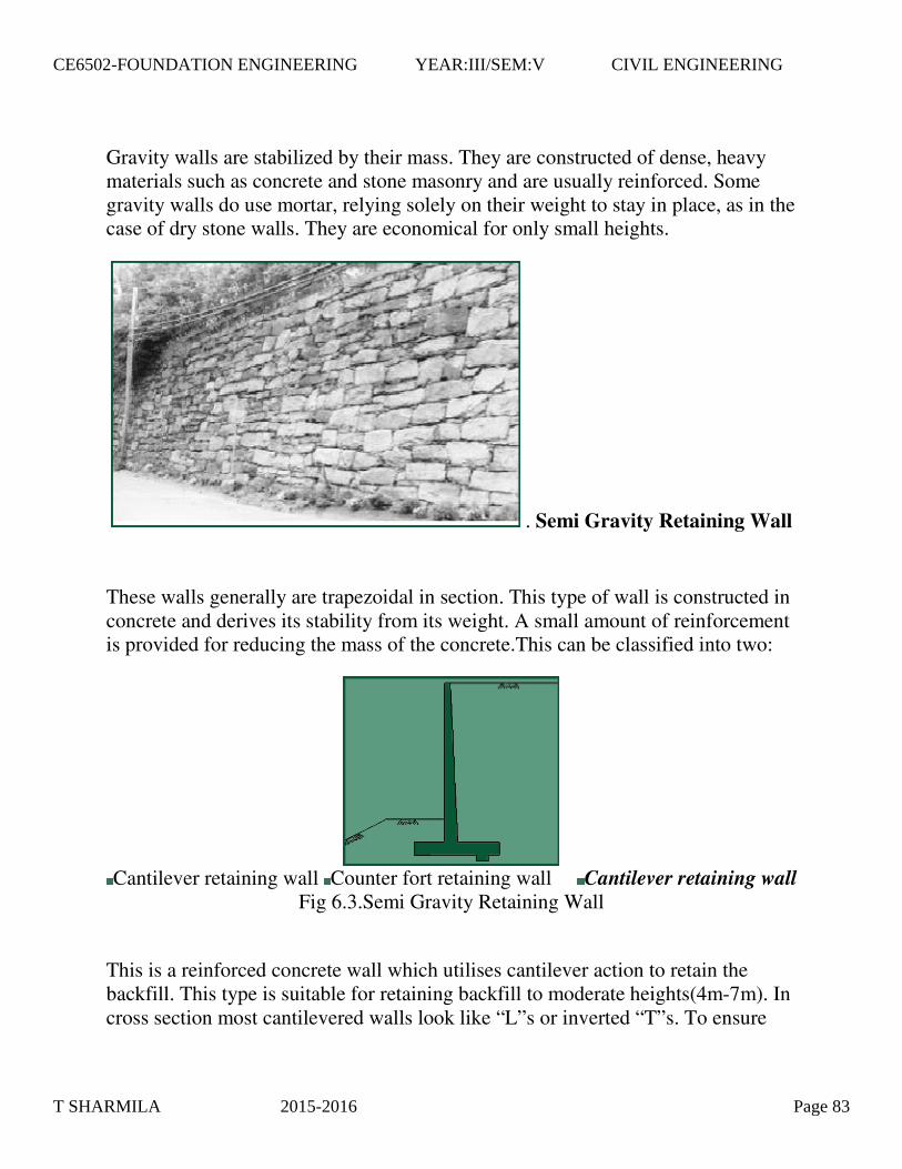
Gravity walls are stabilized by their mass. They are constructed of dense, heavy materials such as concrete and stone masonry and are usually reinforced. Some gravity walls do use mortar, relying solely on their weight to stay in place, as in the case of dry stone walls. They are economical for only small heights.
. Semi Gravity Retaining Wall
These walls generally are trapezoidal in section. This type of wall is constructed in concrete and derives its stability from its weight. A small amount of reinforcement is provided for reducing the mass of the concrete.This can be classified into two:
Cantilever retaining wall Counter fort retaining wall Cantilever retaining wall
Fig 6.3.Semi Gravity Retaining Wall
This is a reinforced concrete wall which utilises cantilever action to retain the backfill. This type is suitable for retaining backfill to moderate heights(4m-7m). In cross section most cantilevered walls look like “L”s or inverted “T”s. To ensure
T SHARMILA 2015-2016 Page 83
CE6502-FOUNDATION ENGINEERING YEAR:III/SEM:V CIVIL ENGINEERING

stability, they are built on solid foundations with the base tied to the vertical portion of the wall with reinforcement rods. The base is then backfilled to counteract forward pressure on the vertical portion of the wall. The cantilevered base is reinforced and is designed to prevent uplifting at the heel of the base, making the wall strong and stable. Local building codes, frost penetration levels and soil qualities determine the foundation and structural requirements of taller cantilevered walls. Reinforced concrete cantilevered walls sometimes have a batter. They can be faced with stone, brick, or simulated veneers. Their front faces can also be surfaced with a variety of textures. Reinforced Concrete Cantilevered Walls are built using forms. When the use of forms is not desired, Reinforced Concrete Block Cantilevered Walls are another option. Where foundation soils are poor, Earth Tieback Retaining Walls are another choice. These walls are counterbalanced not only by a large base but also by a series of horizontal bars or strips extending out perpendicularly from the vertical surface into the slope. The bars or strips, sometimes called “deadmen” are made of wood, metal, or synthetic materials such as geotextiles. Once an earth tieback retaining wall is backfilled, the weight and friction of the fill against the horizontal members anchors the structure.
When the height of the cantilever retaining wall is more than about 7m, it is economical to provide vertical bracing system known as counter forts. In this case, both base slab and face of wall span horizontally between the counter forts.
Fig. 6.5 Counter fort retaining wall
5.3.Counterfort retaining wall
T SHARMILA 2015-2016 Page 84
CE6502-FOUNDATION ENGINEERING YEAR:III/SEM:V CIVIL ENGINEERING

3. Flexible walls: there are two classes of flexible walls. A.
Sheet pile walls and B.
Diaphragm wall A. Sheet Pile Walls Sheet piles are generally made of steel or
timber. The use of timber piles is generally limited to temporary sdtructures in
which the depth of driving does not exceed 3m. for permanent structures and for
depth of driving greater than 3m, steel piles are most suitable. Moreover, steel iles
are relatively water tight and can be extracted if required and reused. However, the
cost of sheet steel piles is generally more than that of timber piles. Reinforced
cement concrete piles are generally used when these are to be jetted into fine sand
or driven in very soft soils, such as peat. For tougher soils , the concrete piles
generally break off. Based on its structural form and loading system, sheet pile
walls can be classified into 2 types:(i)Cantilever Sheet Piles and(ii)Anchored Sheet
Piles 1. Cantilever sheet pile walls:
Fig. 6.6.Cantilever sheet pile wall Cantilever sheet piles are further divide into two types: Free cantilever sheet
pile It is a sheet pile subjected to a concentrated horizontal load at its top.
There is no back fill above the dredge level. The free cantilever sheet pile
derives its stability entirely from the lateral passive resistance of the soil below
the dredge level into which it is driven. Cantilever Sheet Pile Wall with
Backfill
T SHARMILA 2015-2016 Page 85
CE6502-FOUNDATION ENGINEERING YEAR:III/SEM:V CIVIL ENGINEERING

A cantilever sheet pile retains backfill at a higher level on one side. The stability is entirely from the lateral passive resistance of the soil into which the sheet pile is driven, like that of a free cantilever sheet pile.
2. Anchored sheet pile walls Anchored shet pile walls are held above the driven depth by anchors provided ata suitable level. The anchors provided for the stability of the sheet ile , in addition tomthe lateral passive resistance of the soil into which the shet piles are driven. The anchored sheet piles are also of two types.
Fig. 6.7.Anchored sheet pile wall
Free earth support piles. An anchored pile is said to have free earth support
when the depth of embedment is small and the pile rotates at its bottom tip. Thus
there is a point of contraflexure in the pile. Fixed earth support piles. An
anchored sheet pile has fixed earth support when the depth of embedment is large.
The bottom tip of the pile is fixed against rotations. There is a change in the
curvature of the pile, and hence, an inflection point occurs. Diaphragm Walls
Diaphragm walls are commonly used in congested areas for retention systems and
permanent foundation walls. They can be installed in close proximity to existing
structures, with minimal loss of support to existing foundations. In addition,
construction dewatering is not required, so there is no associated subsidence.
Diaphragm walls have also been used as deep groundwater barriers through and
under dams.
Diaphragm walls are constructed by the slurry trench technique which was developed in Europe, and has been used in the United States since the l940's. The
T SHARMILA 2015-2016 Page 86
CE6502-FOUNDATION ENGINEERING YEAR:III/SEM:V CIVIL ENGINEERING
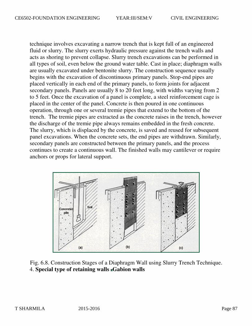
technique involves excavating a narrow trench that is kept full of an engineered fluid or slurry. The slurry exerts hydraulic pressure against the trench walls and acts as shoring to prevent collapse. Slurry trench excavations can be performed in all types of soil, even below the ground water table. Cast in place; diaphragm walls are usually excavated under bentonite slurry. The construction sequence usually begins with the excavation of discontinuous primary panels. Stop-end pipes are placed vertically in each end of the primary panels, to form joints for adjacent secondary panels. Panels are usually 8 to 20 feet long, with widths varying from 2 to 5 feet. Once the excavation of a panel is complete, a steel reinforcement cage is placed in the center of the panel. Concrete is then poured in one continuous operation, through one or several tremie pipes that extend to the bottom of the trench. The tremie pipes are extracted as the concrete raises in the trench, however the discharge of the tremie pipe always remains embedded in the fresh concrete. The slurry, which is displaced by the concrete, is saved and reused for subsequent panel excavations. When the concrete sets, the end pipes are withdrawn. Similarly, secondary panels are constructed between the primary panels, and the process continues to create a continuous wall. The finished walls may cantilever or require anchors or props for lateral support.
� Fig. 6.8. Construction Stages of a Diaphragm Wall using Slurry Trench Technique. 4. Special type of retaining walls Gabion walls
T SHARMILA 2015-2016 Page 87
CE6502-FOUNDATION ENGINEERING YEAR:III/SEM:V CIVIL ENGINEERING

Gabion walls are constructed by stacking and tying wire cages filled with trap rock or native stone on top of one another. They can have a continuous batter (gently sloping) or be stepped back (terraced) with each successively higher course.
This is a good application where the retaining wall needs to allow high amounts of water to pass through it, as in the case of riverbank stabilization. It is important to use a filter fabric with the gabion to keep adjacent soil from flowing into or through the cages along with the water. As relatively flexible structures, they are useful in situations where movement might be anticipated. Vegetation can be re-established around the gabions and can soften the visible edges allowing them to blend into the surrounding landscape. For local roads, they are a preferred low-cost retaining structure.
Fig. 6.9 (i) Gabion Wall
T SHARMILA 2015-2016 Page 88
CE6502-FOUNDATION ENGINEERING YEAR:III/SEM:V CIVIL ENGINEERING
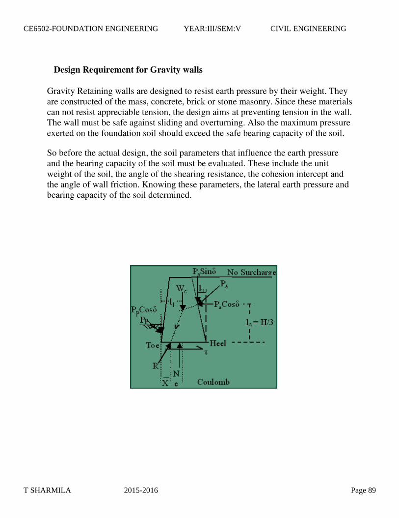
Design Requirement for Gravity walls
Gravity Retaining walls are designed to resist earth pressure by their weight. They are constructed of the mass, concrete, brick or stone masonry. Since these materials can not resist appreciable tension, the design aims at preventing tension in the wall. The wall must be safe against sliding and overturning. Also the maximum pressure exerted on the foundation soil should exceed the safe bearing capacity of the soil.
So before the actual design, the soil parameters that influence the earth pressure and the bearing capacity of the soil must be evaluated. These include the unit weight of the soil, the angle of the shearing resistance, the cohesion intercept and the angle of wall friction. Knowing these parameters, the lateral earth pressure and bearing capacity of the soil determined.
T SHARMILA 2015-2016 Page 89
CE6502-FOUNDATION ENGINEERING YEAR:III/SEM:V CIVIL ENGINEERING

Fig-6.12a Fig-6.12b
Fig. 6.12a shows a typical trapezoidal section of a gravity retaining wall.
The forces acting on the wall per unit length are:
Active Earth pressure . The weight of the wall ( ) The Resultant soil
reaction R on the base. (or Resultant of weight & ).Strike the base at point D. There is equal and opposite reaction R' at the base between the wall and the
foundation. Passive earth pressure acting on the lower portion of the face of the wall, which usually small and usually neglected for design purposes. The full
T SHARMILA 2015-2016 Page 90
CE6502-FOUNDATION ENGINEERING YEAR:III/SEM:V CIVIL ENGINEERING
mobilization of passive earth pressure not occurs at the time of failure so we not consider it. If we consider it then it shows resistance against instability. So if we ignore it then we will be in safer side.
First decide which theory we want to apply for calculating the active earth pressure. Normally we calculate earth pressure using Rankine's theory or Coulomb's Earth pressure theory.
For using Rankine's theory, a vertical line AB is drawn through the heel point
( Fig 6.12-b ). It is assumed that the Rankine active condition exist along the
vertical line AB. While checking the stability, the weight of the soil ( ) above the heel in the zone ABC should also be taken in to consideration, in addition to
the Earth pressure ( ) and weight of the wall ( ).
But Coulomb's theory gives directly the lateral pressure ( ) on the back face of
the wall, the forces to be considered only (Coulomb) and the Weight of the wall
( ). In this case, the weight of soil ( ) is need not be considered.
Once the forces acting on the wall have been determined, the Stability is checked using the procedure discussed in the proceeding section. For convenience, the section of the retaining wall is divided in to rectangles & triangles for the computation of the Weight and the determination of the line of action of the Weight.
For a safe design, the following requirement must be satisfied. No Sliding
Horizontal forces tend to slide the wall away from the fill. This tendency is resisted by friction at the base.
T SHARMILA 2015-2016 Page 91
CE6502-FOUNDATION ENGINEERING YEAR:III/SEM:V CIVIL ENGINEERING

= Coefficient of friction between the base of the wall and soil (= tan ).
= Sum of the all vertical forces i.e. vertical component of inclined active force.
A minimum factor of safety of 1.5 against sliding is recommended.
No Overturning
The wall must be safe against overturning about toe.
No Bearing Capacity Failure and No Tension
First calculate the line of action of the Resultant force ( e ) from centre of the base.
(No Tension will develop at the heel)
T SHARMILA 2015-2016 Page 92
CE6502-FOUNDATION ENGINEERING YEAR:III/SEM:V CIVIL ENGINEERING
The pressure at the toe of the wall must not exceed the allowable bearing capacity of the soil. The pressure at the base is assumed to be linear. The max. Pressure at the Toe & min at the Heel is given by:
should be less than the Safe bearing capacity( ) of the soil &
should not be Tensile in any case. Tension is not desirable. The tensile strength of the soil is very small and tensile crack would develop. The effective base area is reduced.
T SHARMILA 2015-2016 Page 93
CE6502-FOUNDATION ENGINEERING YEAR:III/SEM:V CIVIL ENGINEERING

2 Marks UNIT -1
1. What are the information obtained in general exploration? Preliminary selection of foundation type depth of water, Depth, extent and composition of soil strata Engineering properties required disturbed or partly disturbed
samples approximate values of strength and compressibility
2. Define significant depth?Exploration depth, in general it should be carried out to a depth upto which increasein the pressure due to structural loading is likely to cause shear failure, such depth isknown as significant depth. For footing, depth of exploration =1.5B
3. What are the types of soil samples? Disturbed soil sample Undisturbed soil sample
4. What is the difference between disturbed and undisturbed soil sample? Disturbed soil sample
Natural structure of soils get partly or fully modified and destroyed Undisturbed soil sample
Natural structure and properties remain preserved
5. What are the disadvantages of wash boring? It is a slow process in stiff soil It cannot be used effectively in hard soil, rocks ,etc.
6. What are design features that affect the sample disturbance?Area ratio, inside clearance, outside clearance, inside wall friction, method ofapplying force
7. What are the corrections to be applied to the standard penetration number? Overburden pressure Correction dilatancy correction
8. What are various methods of site exploration?Open exacavation, borings, geophysical methods, sub-surface soundings
9. What are the methods of boring?Auger borings, shell boring, wash boring, rotary boring, percussion boring.
10. Define area ratio?Area ratio is defined as the ratio of maximum cross sectional area of the cuttingedge to the area of the soil sample
11. Define liquefaction of sand?The mass failure occurs suddenly, and the whole mass appears flow laterally as ifit were a liquid such failure is referred to as liquefaction.
T SHARMILA 2015-2016 Page 94
CE6502-FOUNDATION ENGINEERING YEAR:III/SEM:V CIVIL ENGINEERING
12. How will you reduce the area ratio of a sampler?By increasing the size of the soil sample.
13. What is meant by a non- representative sample? Name the laboratory tests thatcould be conducted on this sample.
Soil sample consists of a mixture of soil from different soil strata is callednon- representative sample and the size of the soil grains and mineral constituentshave changed.
14. Write the uses of Bore log Report.(i) Used to record the change of layer’s depth.
(ii) Used to record the water level.(iii)Used to record the water quality in deeper levels.
15. Define detailed exploration.Detailed exploration follows as a supplement to general exploration when
large engineering works, heavy loads, and complex and costly foundations areinvolved. A detailed exploration is meant to furnish information about soilproperties such as shear strength, compressibility, density index, andpermeability.
16.What are the limitations of hand augers in soil exploration?
1. Hand augers are not suitable for sands and gravels above the water table.2. The sample is distributed and suitable for identification purposes only.
17. What are the guidelines in terms of inside clearance and outside clearancefor obtaining undisturbed sample?
An undisturbed sample is that in which the natural structure and properties remainpreserved. The inside clearance should lie between 1 to 3 percent and the outsideclearance. The walls of the sampler should be smooth and should be kept properly oiled.
18. List the various methods of soil exploration techniques.1. Pits and trenches2. Boring a) augur boring b) wash or water boring c) rotary boring d) percussionboring3. Geophysical methods a) seismic refraction b) electrical resistivity4. Standard penetration test5. Static cone penetration test
19. Write short notes on Augur boring.An augur is a type of tool which is used for understanding the characteristics of the
subsurface soil. Generally there are two types of augurs, a) Manually operated augur b)Mechanically operated augur
20. Define standard penetration number.The number of blows required to penetrate 300 mm of the split spoon
sampler beyond a seating drive of 150mm is known as penetration number (N).
T SHARMILA 2015-2016 Page 95
CE6502-FOUNDATION ENGINEERING YEAR:III/SEM:V CIVIL ENGINEERING

21. List the various corrections to be carried out in SPT test.The two corrections are
a) Dilatancy correction ( Silty sand)b) Over burden pressure correction ( Granular soil)22. What are the uses of soil exploration?
a) To select type and depth of foundation for a given structureb) To determine the bearing capacity of the soil of the selected foundation c)To investigate the safety of the existing structured) To establish ground water level
23. What is soil exploration?The process of collection subsoil sample by an appropriate method to a neededdepth and check those samples for knowing the properties is called soil exploration.
24. List the different types of samplers.a) Standard split spoon samplerb) Shelby and thin walled tube samplerc) Denison samplerd) Piston samplere) Scraper bucket sampler25. List the various parameters affecting the sampling disturbance.a) Area ratiob) Inside clearancec) Outside clearanced) Inside wall frictione) Position of non return wall
f) Recovery ratiog) Methods of applying force
26. Write the advantages of SCPT over SPT.a) There is no need of hammering action, just pushing into the ground. b)No need of bore holes, it is carried out on the groundc) Engineering properties of the soil like permeability, Shear
strength,Compressibility can be evaluated.
27. Write short notes on spacing of bore holes.The spacing of bore holes depends upon the variation of subsurface soil in
the horizontal direction. The factors influencing the spacing of bore holes are, a) Type ofsoilb) Fluctuation of water tablec) Load coming from structured) Importance of the structure.e) Economical feasibility.
T SHARMILA 2015-2016 Page 96
CE6502-FOUNDATION ENGINEERING YEAR:III/SEM:V CIVIL ENGINEERING
UNIT -21. What are components of total foundation settlement?
Elastic settlement, consolidation settlement, secondary consolidation settlement
2. What are the types of shear failure?General shear failure, local shear failure, punching shear failure
3. What are assumptions in Terzaghi’s bearing capacity theory?- the base of the footing is rough- the load on footing is vertical and uniformly distributed- the footing is continuous
4. List out the methods of computing elastic settlements?based on the theory of elasticity, Pressure meter method, Janhu –Bjerram method,Schmentmann’s method
5. What are the limitation of Terzaghi’s analysis?- As the soil compresses, pi changes slight down ward movement of footing may
not develop fully the plastic zones- Error due to assumption that the resultant passive pressure consists of three
components is small
6. Define ultimate bearing capacity?Gross pressure at the base of the foundation at which the soil fails in shear iscalled ultimate bearing capacity.
7. Define net ultimate bearing capacity ?Net pressure increase in pressure at the base of the foundation that causes failurein shear, is called as net ultimate bearing capacity
8. Define allowable bearing capacity?It is the net loading intensity at which neither the soil fails in shear nor there isexcessive settlement detrimental to the structure
9. Write the expression for correction due to dilatancy submergence?Ne = 15 + ( No-15 )
10.What are the requirements for a stable foundation?-must be safe from failure-must be properly located-must not settle or deflect sufficiently to damage the structure or impair itsusefulness.
11. What are the factors which depends depth?Type of soil, size of structure, magnitude of loads, environmental conditions, etc
T SHARMILA 2015-2016 Page 97
CE6502-FOUNDATION ENGINEERING YEAR:III/SEM:V CIVIL ENGINEERING
12 .Define net pressure intensity ?It is the excess pressure, of the gross pressure after the construction of the structureand the original overburden pressure.
13. What are the zones used in the Terzaghi’s bearing capacity analysis for dividing thefailure envelope of the soil.?
Elastic equilibrium zone, Radial Stress zone, plastic zone
14. Write the ultimate bearing capacity equation for the general shear failure of soil inTerzaghi’s analysis for a strip footing.
qu = c Nc + γDNq + 0.5 γB Nγ
15. Define Shallow foundation.If the depth of the foundation is less than its breadth, such foundation is known asshallow foundation.
17. Write down the equation for estimating the elastic settlement based on the theory ofelasticity.?
18. When will the total settlement be completed in the case of cohesion-less soil?Once the construction is over, the total settlement is assumed to be completed.
19. Define differential settlementIf any two points of the foundation base experiences different settlements thensuch settlement is known as differential settlement.
20. What type of shear failure of soil is more likely to happen in the case of very densesoil?
usually punching shear failure and local shear failure may also be possible.
21. Write the ultimate bearing capacity equation for the general shear failure of soil inTerzaghi’s analysis for a square footing.
qu = 1.3 cNc + γD Nq + 0.4 γB Nγ
22. When will the Consolidation settlement get completed?In the case of cohesion-less soil, the consolidation settlement gets completed oncethe construction is over. But In the case of cohesive soil, the consolidationsettlement takes place for several years.
24. Define Deep foundationIf the depth of the foundation is equal to or greater than the breadth of thefoundation such foundation is called as deep foundation.
25. For which type of foundation, Terzaghi’s bearing capacity equation is applicable.Why?
Shallow foundation only. Because the effect of the depth is not considered.
T SHARMILA 2015-2016 Page 98
CE6502-FOUNDATION ENGINEERING YEAR:III/SEM:V CIVIL ENGINEERING

UNIT –III
1. Under what circumstances, a strap footing is adopted?When the distance between the two columns is so great, so that trapezoidalfooting is very narrow and so it is uneconomical. It transfers the heavy load of onecolumn to other column.
2. What is a mat foundation?It is a combined footing that covers the entire area beneath a structure andsupports all the walls and columns.
3. Where mat foundation is used?It is used when the area of isolated footing is more than fifty percentage of wholearea or the soil bearing capacity is very poor.
4. Define spread footing?It is a type of shallow foundation used to transmit the load of isolated column, orthat of wall to sub soil. The base of footing is enlarged and spread to provideindividual support for load.
5. What are types of foundation?shallow foundation , deep foundation
6. What are the footings comes under shallow foundation?spread footing or pad footings , strap footings, combined footings,raft or mat foundation
7. What are the footings comes under deep foundation?pile, caisons(well foundation)
8. Define floating foundation?It is defined as a foundation in which the weight of the building is approximatelyequal to the full weight of the soil including water excavated from the site of thebuilding.
9. What is mean by proportioning of footing?Footings are proportional such that the applied load including the self weight ofthe footing including soil .the action are not exceeding the safe bearing capacityof the soil.
10. What are the assumptions made in combined footing?- the footing is rigid and rests on a homogenous soil to give rise to linear stressdistribution on the bottom of the footing.
- the resultant of the soil pressure coincides with the resultant of the loads,then it is assumed to be uniformly distributed.
T SHARMILA 2015-2016 Page 99
CE6502-FOUNDATION ENGINEERING YEAR:III/SEM:V CIVIL ENGINEERING

UNIT -IV
1. List out the type of pile based on material used?timber pile, concrete pile, steel pile, composite pile
2. How is the selection of pile carried out?The selection of the type, length and capacity is usually made from estimationbased on the soil condition and magnitude of the load.
3. What is mean by group settlement ratio?The settlement of pile group is found to be many times that of a single pile. Theratio of the settlement of the pile group to that of a single pile is known as thegroup settlement ratio.
4. What are the factors consider while selecting the type of pile?-the loads-time available for completion of the job-availability of equipment-the ground water conditions-the characteristics of the soil strata involved
5. What are the type of hammer?drop hammer, diesel hammer, double acting hammer,single acting hammer, vibratory hammer
6. What is pile driver?Piles are commonly driven by means of a hammer supported by a crane or by aspecial device known as a pile driver.
7. What are methods to determine the load carrying capacity of a pile?- dynamic formulae- static formula- pile load test- penetration tests
8. What are the two types of dynamic formulae?- Engg. news formula- Hiley’s formula
9. What is meant by single-under reamed pile?The pile has only one bulb is known as single under reamed pile.
10. Write down the static formulae?The static formulae are based on assumption that the ultimate bearing capacityQup of a pile is the sum of the ultimate skin friction Rf and total ultimate point orand bearing resistance Rp.
Qup=Rf+RpQup=Asrf+Ap.rp
T SHARMILA 2015-2016 Page 100
CE6502-FOUNDATION ENGINEERING YEAR:III/SEM:V CIVIL ENGINEERING

UNIT -V1. Define conjugate stresses?
The stress acting on the conjugate planes is called conjugate stresses
2. How do you check the stability of retaining walls? The wall should be stable against sliding The wall should be stable against overturning The base of the wall should be stable against bearing capacity failure
3. Define angle of repose ?Maximum natural slope at which the soil particles may rest due to their internalfriction, if left unsupported for sufficient length of time
4. Define theory of plasticity?The theory on which the condition of the stress in a state of a plastic equilibrium iscalled as theory of plasticity.
5. What are assumption in coulomb wedge theory?- the backfill is dry, cohesionless, isotropic, homogenous,
- the slip surface is plane which passes through the head of the wall
6. How to prevent land sliding?Sheet piles, retaining wall may be used to prevent the land sliding
7. Write down any two assumptions of Rankine’s theory?- semi infinite soil- cohesion-less backfill- homogenous soil- the top surface is a plane which may be inclined or horizontal.
8. Distinguish Coloumb’s wedge theory from Rankine’s theory?Rankine considered a soil particle at plastic equilibrium but Coulomb consideredthe whole soil mass.
16 Marks Unit 11. Explain any two methods of site exploration in detail?
The various methods of site exploration may be grouped as follows:1. Open excavations. Trial pits are the cheapest method of exploration in shallowdeposits, since these can be used in all types of soils.
Soils are inspected in the natural conditions and samples, disturbed andundisturbed can be conveniently taken.
The cost of open excavation increases rapidly with depth. They are generally considered suiable for shallow depths(say upto 3 m).
2. Borings. The following are the various boring methods commonly used:(i) Augerboring.(ii) Auger and shell boring.(iii) Wash boring.(iv) Percussion boring.(v) Rotaryboring
T SHARMILA 2015-2016 Page 101
CE6502-FOUNDATION ENGINEERING YEAR:III/SEM:V CIVIL ENGINEERING
3. Sub-surface soundings. The sounding methods consist of measuring the resistanceof the soil with depth by means of penetrometer under static or dynamic loading. Thepenetrorneter may consist of a sampling spoon, a cone or other shaped tool. Theresistance to penetration is empirically correlated with some of the engineeringproperties of soil, such as density index, consistency, bearing capacity etc.4. Geo-physical methods. Geo-physical methods are used when the depth ofexploration is very large, and also when the speed of investigation is of primaryimportance. Geo-physical investigations involve the detecttion of significantdifferences in the physical properties of geological formations.
2. Explain wash boring method of soil exploration?The boring methods are used for exploration at greater depths where direct methods
fail. These provide both disturbed as well as undisturbed samples depending upon themethod of boring. In selecting the boring method for a particular job, consideration shouldbe made for the following:The materials to be encountered and the relative efficiency of the various boring methods insuch materials. The available facility and accuracy with which changes in the soil andground water conditions can be determined. Possible disturbance of the material to besampled.
The different types of boring methods are:1. Displacement boring.2. Wash boring.3. Auger boring.4. Rotary drilling.5. Percussion drilling.6. Continuous sampling.
1. Displacement borings It is combined method of sampling & boring operation. Closed bottom sampler, slit
cup, or piston type is forced in to the ground up to the desired depth. Then thesampler is detached from soil below it, by rotating the piston, & finally the piston isreleased or withdrawn.
The sampler is then again forced further down & sample is taken. After withdrawal of sampler & removal of sample from sampler, the sampler is
kept in closed condition & again used for another depth.Features :
Simple and economic method if excessive caving does not occur. Therefore notsuitable for loose sand.
Major changes of soil character can be detected by means of penetration resistance. These are 25mm to 75mm holes. It requires fairly continuous sampling in stiff and dense soil, either to protect the
sampler from damage or to avoid objectionably heavy construction pit.2. Wash boring:
It is a popular method due to the use of limited equipments.
T SHARMILA 2015-2016 Page 102
CE6502-FOUNDATION ENGINEERING YEAR:III/SEM:V CIVIL ENGINEERING
The advantage of this is the use of inexpensive and easily portable handling anddrilling equipments.
Here first an open hole is formed on the ground so that the soil sampling or rockdrilling operation can be done below the hole.
3. Auger boring This method is fast and economical, using simple, light, flexible and inexpensive
instruments for large to small holes. It is very suitable for soft to stiff cohesive soils and also can be used to determine
ground water table. Soil removed by this is disturbed but it is better than wash boring, percussion or
rotary drilling. It is not suitable for very hard or cemented soils, very soft soils, asthen the flow into the hole can occur and also for fully saturated cohesionless soil.
4. Rotary drilling Rotary drilling method of boring is useful in case of highly resistant strata. It is related to finding out the rock strata and also to access the quality of rocks
from cracks, fissures and joints. It can conveniently be used in sands and silts also. Here, the bore holes are advanced in depth by rotary percussion method which is
similar to wash boring technique. A heavy string of the drill rod is used for choking action. The broken rock or soil fragments are removed by circulating water or drilling mud
pumped through the drill rods and bit up through the bore hole from which it iscollected in a settling tank for recirculation.
If the depth is small and the soil stable, water alone can be used. However, drilling fluids are useful as they serve to stabilize the bore hole. Drilling
T SHARMILA 2015-2016 Page 103
CE6502-FOUNDATION ENGINEERING YEAR:III/SEM:V CIVIL ENGINEERING
CE 2305 FOUNDATION ENGINEERING YEAR: III/SEM: V CIVIL ENGINEERING
Fig.1.3 Rotary Drilling System
3. Explain about standard penetration test?In-situ tests General The in situ tests in the field have the advantage of testing the soils intheir natural, undisturbed condition. Laboratory tests, on the other hand, make use of smallsize samples obtained from boreholes through samplers and therefore the reliability of thesedepends on the quality of the so called ‘undisturbed' samples. Further, obtainingundisturbed samples from non-cohesive, granular soils is not easy, if not impossible.Therefore, it is common practice to rely more on laboratory tests where cohesive soils areconcerned. Further, in such soils, the field tests being short duration tests, fail to yieldmeaningful consolidation settlement data in any case. Where the subsoil strata areessentially non-cohesive in character, the bias is most definitely towards field tests. Thedata from field tests is used in empirical, but time-tested correlations to predict settlementof foundations. The field tests commonly used in subsurface investigation are:
Penetrometer test Pressuremeter test Vane shear test Plate load test Geophysical methods
Penetrometer Tests :
Standard penetration test (SPT) Static cone penetration test (CPT) Dynamic cone penetration test (DCPT) Standard penetration test
The standard penetration test is carried out in a borehole, while the DCPT and SCPT arecarried out without a borehole. All the three tests measure the resistance of the soil strata topenetration by a penetrometer. Useful empirical correlations between penetration resistanceand soil properties are available for use in foundation design.
T SHARMILA 2015-2016 Page 104
CE6502-FOUNDATION ENGINEERING YEAR:III/SEM:V CIVIL ENGINEERING

This is the most extensively used penetrometer test and employs a split-spoon sampler,which consists of a driving shoe, a split-barrel of circular cross-section which islongitudinally split into two parts and a coupling. IS: 2131-1981 gives the standard forcarrying out the test.
Procedure
The borehole is advanced to the required depth and the bottom cleaned. The split-spoon sampler, attached to standard drill rods of required length is
lowered into the borehole and rested at the bottom . The split-spoon sampler is driven into the soil for a distance of 450mm by blows
of a drop hammer (monkey) of 65 kg falling vertically and freely from a height of750 mm.
The number of blows required to penetrate every 150 mm is recorded while drivingthe sampler.
The number of blows required for the last 300 mm of penetration is added togetherand recorded as the N value at that particular depth of the borehole.
The number of blows required to effect the first 150mm of penetration, called theseating drive, is disregarded.
The split-spoon sampler is then withdrawn and is detached from the drill rods. The split-barrel is disconnected from the cutting shoe and the coupling. The soil sample collected inside the split barrel is carefully collected so as to
preserve the natural moisture content and transported to the laboratory for tests. Sometimes, a thin liner is inserted within the split-barrel so that at the end of the
SPT, the liner containing the soil sample is sealed with molten wax at both its endsbefore it is taken away to the laboratory.
The SPT is carried out at every 0.75 m vertical intervals in a borehole. This can be increased to 1.50 m if the depth of borehole is large. Due to the presence of boulders or rocks, it may not be possible to drive the sampler
to a distance of 450 mm. In such a case, the N value can be recorded for the first 300 mm penetration. The
boring log shows refusal and the test is halted if 50 blows are required for any 150mm penetration 100 blows are required for 300m penetration 10 successive blows produce no advance.
Precautions
The drill rods should be of standard specification and should not be in bentcondition.
The split spoon sampler must be in good condition and the cutting shoe must be freefrom wear and tear.
The drop hammer must be of the right weight and the fall should be free,frictionless and vertical. The SPT is carried out at every 0.75 m vertical intervals ina borehole. This can be increased to 1.50 m if the depth of borehole is large. Due tothe presence of boulders or rocks, it may not be possible to drive the sampler to a
T SHARMILA 2015-2016 Page 105
CE6502-FOUNDATION ENGINEERING YEAR:III/SEM:V CIVIL ENGINEERING
distance of 450 mm. In such a case, the N value can be recorded for the first 300mm penetration. The boring log shows refusal and the test is halted if
50 blows are required for any 150mm penetration 100 blows are required for 300m penetration 10 successive blows produce no advance.
The height of fall must be exactly 750 mm. Any change from this will seriouslyaffect the N value.
The bottom of the borehole must be properly cleaned before the test is carried out. Ifthis is not done, the test gets carried out in the loose, disturbed soil and not in theundisturbed soil. When a casing is used in borehole, it should be ensured that thecasing is driven just short of the level at which the SPT is to be carried out.Otherwise, the test gets carried out in a soil plug enclosed at the bottom of thecasing.
When the test is carried out in a sandy soil below the water table, it must be ensuredthat the water level in the borehole is always maintained slightly above the groundwater level.
If the water level in the borehole is lower than the ground water level, ‘quick'condition may develop in the soil and very low N values may be recorded.
In spite of all these imperfections, SPT is still extensively used because the test issimple and relatively economical.
it is the only test that provides representative soil samples both for visual inspectionin the field and for natural moisture content and classification tests in thelaboratory.
SPT values obtained in the field for sand have to be corrected before they are usedin empirical correlations and design charts. IS: 2131-1981 recommends that thefield value of N be corrected for two effects, namely, (a) effect of overburdenpressure, and (b) effect of dilatancy. (a) Correction for overburden pressure
Several investigators have found that the penetration resistance or the N value in agranular soil is influenced by the overburden pressure.
Of two granular soils possessing the same relative density but having differentconfining pressures, the one with a higher confining pressure gives a higher Nvalue.
Since the confining pressure (which is directly proportional to the overburdenpressure) increases with depth, the N values at shallow depths are underestimatedand the N values at larger depths are overestimated.
To allow for this, N values recorded from field tests at different effectiveoverburden pressures are corrected to a standard effective overburden pressure.
T SHARMILA 2015-2016 Page 106
CE6502-FOUNDATION ENGINEERING YEAR:III/SEM:V CIVIL ENGINEERING
4. Explain any two important types of samplersTypes of Samplers
The samplers are classified as thick wall or thin wall samplers depending upon thearea ratio. Thick wall samplers are those having the area ratio greater than 10 percent.Depending upon the mode of operation, samplers may be classified in the followingthree common types : (i) open drive sampler (including split spoon samplers), (ii)stationary piston sampler and (iii) rotary sampler.
The open drive sampler is a tube open at its lower end. The sampler head is provided with vent +41s (valve)
to permit water and air to escape during driving. The check valve helps to retainsample when the sampler is lifted up. The tube may be seamless or it may be split intwo parts; in the latter case it is known as split spoon sampler.
The stationary piston sampler consists of a Sample cylinder and the piston system.During lowering of the sampler through the hole, the lower end of the sampler is keptclosed with the piston. When the desired sampling elevation is reached, ihe piston rodis clamped, thereby keeping the piston stationary, and the sampler tube is advanceddown into the soil. The sampler is then Lifted up, with piston rod clamped in position.The sampler is more suitable for sampling soft soils saturated sands.
Rotatory samplers are the core barrel type having an outer tube provided with cuttingteeth and a removable thin wall liner inside. It is used for firm to hard cohesive soils
T SHARMILA 2015-2016 Page 107
CE6502-FOUNDATION ENGINEERING YEAR:III/SEM:V CIVIL ENGINEERING

and cemented soils.
5. Explain with neat sketch auger boring method of soil exploration.The following are the various boring methods commonly used:
(i) Auger boring.(ii) Auger and shell boring.(iii) Wash boring.(iv) Percussion boring.(v) Rotary boring.
(i) Auger boringAugers are used in cohesive and other soft soils aboye water table. They may either beoperated manually or mechanically. Hand augers are used upto a depth upto 6 m.Mechanically operated augers are used for greater depths and they can also be used ingravelly soils. Augers are of two types: (a) spiral auger and (b) post-hole auger.
FIG. 2.12 AUGER.
Samples recovered from the soil brought up by the augers are badly disturbed and areuseful for identification purposes only. Auger boring is fairly satisfactory brexplorations at shallow depths and for exploratory borrow pits.
(ii) Auger and shell boringCylindrical augers and shells with cutting edge or teeth at Iower end can be used formaking deep borings. Hand operated rigs are used for depths upto 25 m andmechanised rigs up to 50 m. Augers are suitable for soft to stiff clays, shells for verystiff and hard clays, and shells or sand pumps for sandy soils. Small boulders, thin softstrata or rock or cemented gravel can be broken by chisel bits attached to drill rods.The hole usually requires a casing. Fig. 2.13 shows a typical sand pump.
T SHARMILA 2015-2016 Page 108
CE6502-FOUNDATION ENGINEERING YEAR:III/SEM:V CIVIL ENGINEERING

CE 2305 FOUNDATION ENGINEERING YEAR: III/SEM: V CIVIL ENGINEERING
FIG. 2.13 SAND PUMP
(iii) Wash boringWash boring is a fast and simple method for advancing holes in all types of soils.Boulders and rock cannot be penetrated by this method. The method consists of firstdriving a casing through which a hollow drilled rod with a sharp chisel or chopping bitat the lower end is inserted. Water is forced under pressure through the dril rod whichis alternativety raised and dropped, and also rotated. The resulting chopping andjetting action of the bit and water disintegrates the soil. The cuttings are forced uptothe ground surface in the form of soil-water slurry through the annular space betweenthe drill rod and the casing. The change in soil stratification could be guessed from therate of progress and colour of wash water. The samples recovered from the wash waterare almost valueless for interpreting the correct geo-technical properties of soil.
(iv) Percussion boringIn this method, soil and rock formations are broken by repeated blows of heavy chieselor bit suspended by a cable or drill rod. Water is added to the hole during boring, ifnot already present and the slurry of pulverised material is bailed out at intervals. Themethod is suitable for advancing a hole in all types of solis, boulders and rock. Theformations, however, get disturbed by the impact.
(v) Rotary boringRotary boring or rotay drilling is a very fast method of advancing hole in both rocksand soils. A . drill bit, fixed to the lower end of the drill rods, is rotated by a suitablechuck, and is always kept in firm contact with the bottom of the hole. A drilling mud,usually a water solution of bentonite, with or without other admixtures, is continuouslyforced down to the hollow dril rods. The mud returning upwards brings the cuttings tothe surface. The method is also known as mud rotary drilling and the hole usuallyrequires no casing.
T SHARMILA 2015-2016 Page 109
CE6502-FOUNDATION ENGINEERING YEAR:III/SEM:V CIVIL ENGINEERING

CE 2305 FOUNDATION ENGINEERING YEAR: III/SEM: V CIVIL ENGINEERING
Rotary core barrels, provided with commercial diamond-studded bits or a steel bit withshots, are also used for rotary drilhng and simultaneously obtaining the rock cores orsamples. The method is them also known as core boring or core drilling. Water 15circulated down drill rods during boring.
FIG. 2.14 WASH BORING.6. Describe the salient features of a good sub-soil investigation report?
A borehole log should give details of the foreman driller’s log, the observations of thesupervising engineer and the results of any site tests. A typical borehole log is shown inFig. 3.6.
Trial pits, trenches and boreholes should be given reference numbers, located on plan,their ground level noted and the date of excavation recorded. It is advisable to recordthe following additional information:
(1) Type of rig, diameter and depth of bore or width of bucket.(2) Diameter and depth of any casing used and why it was necessary.(3) Depth of each change of strata and a full description of the strata. (Was the soil virginground or fill?)(4) Depths at which samples taken, type of sample and sample reference number.(5) In situ test depth and reference number.(6) The levels at which groundwater was first noted; the rate of rise of the water; its levelat start and end ofeach day. (When more information on permeability, porewater pressure, and the like is
T SHARMILA 2015-2016 Page 110
CE6502-FOUNDATION ENGINEERING YEAR:III/SEM:V CIVIL ENGINEERING

required, then it is vitally important that the use of piezometers should be considered.)(7) Depth and description of obstructions (i.e. boulders), services (drains) or cavitiesencountered.(8) Rate of boring or excavation (useful to contractors and piling sub-contractors as suchinformation gives some guidance in ease of excavation or pile driving).(9) Name of supervising engineer.(10) Date and weather conditions during investigation.
Fig. Example of a typical borehole log (BS 5930).7.Explain various types of Samles. Also discuss various factors affecting quality ofsamples?
Soil samples can be of two types:
T SHARMILA 2015-2016 Page 111
CE6502-FOUNDATION ENGINEERING YEAR:III/SEM:V CIVIL ENGINEERING
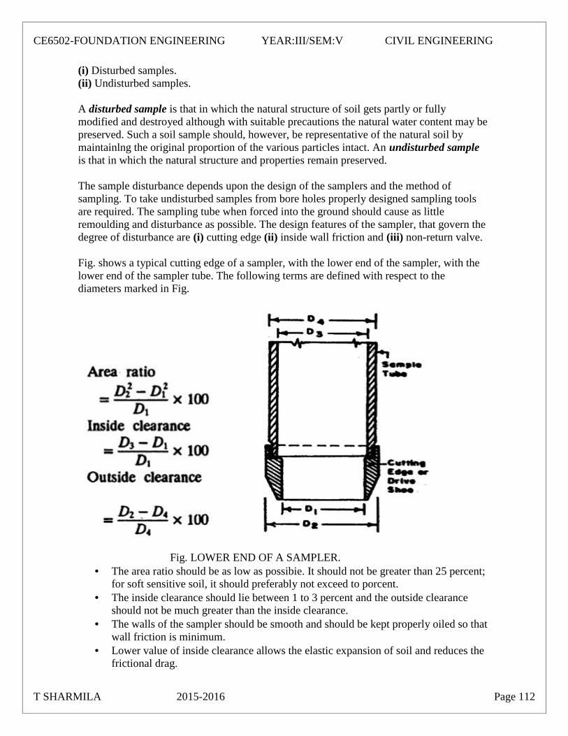
(i) Disturbed samples.(ii) Undisturbed samples.
A disturbed sample is that in which the natural structure of soil gets partly or fullymodified and destroyed although with suitable precautions the natural water content may bepreserved. Such a soil sample should, however, be representative of the natural soil bymaintainlng the original proportion of the various particles intact. An undisturbed sampleis that in which the natural structure and properties remain preserved.
The sample disturbance depends upon the design of the samplers and the method ofsampling. To take undisturbed samples from bore holes properly designed sampling toolsare required. The sampling tube when forced into the ground should cause as littleremoulding and disturbance as possible. The design features of the sampler, that govern thedegree of disturbance are (i) cutting edge (ii) inside wall friction and (iii) non-return valve.
Fig. shows a typical cutting edge of a sampler, with the lower end of the sampler, with thelower end of the sampler tube. The following terms are defined with respect to thediameters marked in Fig.
Fig. LOWER END OF A SAMPLER. The area ratio should be as low as possibie. It should not be greater than 25 percent;
for soft sensitive soil, it should preferably not exceed to porcent. The inside clearance should lie between 1 to 3 percent and the outside clearance
should not be much greater than the inside clearance. The walls of the sampler should be smooth and should be kept properly oiled so that
wall friction is minimum. Lower value of inside clearance allows the elastic expansion of soil and reduces the
frictional drag.
T SHARMILA 2015-2016 Page 112
CE6502-FOUNDATION ENGINEERING YEAR:III/SEM:V CIVIL ENGINEERING

The non-retum valve, invariably provided in samplers, should permit easy and quickescape of water and air when driving the sampler.
UNIT -II
1. A Square footing of 1.2 m x1.2m rest at depth of 1m in saturated clay layer 4mdeep. The clay is normally consolidated having an unconfined compressive
strength of 40 kN/m2. The soil has a liquid limit 30%, sat = 17.8 kN/m3,W=28% and G = 2.68. Determine the load which the footing can carry safelywith a a factor of safety of 3 against shear. Also, determine the settlement if thefooting is loaded with this safe load. Use Terzahi’s analysis for bearingcapacity.
Ans: Since ∅= 0, Nc = 5.7, Nq= 1and N = 0Also, = = 17.8
C= qu/2 =40/2= 20 kN/m2
qs = qnf + sat DF
(or) 1qs = [ 1.3 cNc + (Nq-1) +0.04 B . N ] + sat D
F
(or) 1qs = [ 1.3 x 20 x 5.7 + 17.8(1-1) + 0] + 17.8
3=49.4 + 17.8 = 67.2 kN/m2∴ Qs = qs x B2 =67.2 x 1.2 x 1.2 =96.77 kN.
Thickness of clay layer = 4 m. Depth of centre of clay layer, below footingLevel =4/2 – 1 =1 m. Assuming load dispersion at 45° width of load spread = 1.2 +2(1) = 3.2 m.∴ Vertical stress increment due to foundation load= ∆ = 96.77 = 9.45 kN / m2.
3.2 x 3.2
Now, the consolidation settlement of footing is given by,
Cc 0 + ∆Sc = C H log10
1 + e0 0
Assume C = 1
T SHARMILA 2015-2016 Page 113
CE6502-FOUNDATION ENGINEERING YEAR:III/SEM:V CIVIL ENGINEERING
e0 = w sat G = 0.28 x 2.68 = 0.75
Cc = 0.009(wL - 10) = 0.009(30 -10) = 0.18
Initial over burden pressure at the centre of clay layer
= 0 = sat Z = 17.8 x 2 = 35.6 kN / m2
0.18 35.6 + 9.45∴ c = x 4 log10
1+ 0.75 35.6
= 0.042 m = 42 mm.
2. The results of two plate load tests for a settlement of 25.4mm are given.Plate diameter Load
0.3 m 31 kN0.6 m 65 kN
A square column foundation is to be designed to carry a load of 800 kN with anallowable settlement of 25.4 mm. Determine the size of the foundation usingHousel’s method.
Ans: Given data:
Q1 = 31 kN d1 = 0.3 m
Q2 = 65 kN d2 = 0.6 m
Q = 800 kN , 25.4 mm.
To find:
Size of the foundation using Housel’s method.
Solution:
Q1 = A1m + P1n …..(1)
Q2 = A2m + P2n .….(2)
Q = Am + Pn .….(3)
T SHARMILA 2015-2016 Page 114
CE6502-FOUNDATION ENGINEERING YEAR:III/SEM:V CIVIL ENGINEERING

d21 x 0.32
A1= = = 70.685 x 10⁻³ m2
4 4d2
2 x 0.82
A2= = = 282.74 x 10⁻³ m2
4 4P1 = x d1 = x 0.3 = 0.942 m
P2 = x d2= x 0.6 = 1.884 m
31 = 70.685 x 10⁻³ m + 0.992 n …..(A)
65 = 282.74 x 10⁻³ m + 1.884 n .…..(B)
Solving equation A and B,
M = 21.22, n = 31.3,
Q = Am + Pn
800 x B2 x 21.22 + (31.31 x 48)
B = 3.86 m say 4m x 4m∴ Size of the foundation 4m x 4m.
3. A square footing for a column is 2.5 m x 2.5 m and carries a load of 2000kN. Find the factor of safety against bearing capacity failure, if the soil hasthe following properties.
C = 50 kN/m2, ∅ =15° ,γ = 17.6 kN/m3
Nc1= 12.5, Nq1= 4.5, Nr1=2.5. The foundation is taken to a depth of 1.5 m.
DataSize of column = 2.5 m x 2.5 mLoad = 2000 kN
C= 50 kN/ m2∅ =15°γ = 17.6 kN/m3
Nc’ = 12.5, Nq’ = 4.5, Nγ’ = 2.5
D = 1.5 m
Solutionqnf =2/3 cNc’Sc + γ D (Nq’-1) Sq+ 0.5 BNγ’Sγ
for square footing
T SHARMILA 2015-2016 Page 115
CE6502-FOUNDATION ENGINEERING YEAR:III/SEM:V CIVIL ENGINEERING

S c = 1.3Sγ=0.8Sq =1.0
qnf = 2/3x 50x12.5x1.3+17.6x1.5(4.5-1)x1+0.5x17.6x2.5x2.5x0.8= 541.67+92.4+44
qnf = 678.07Actual load intensity qa =Load = 2000
Area 2.5x2.5
qa = 320 kN/m2
We know that qa = qs∴ qs =qnf + γ DF
320-17.6x1.5=678.07F∴ F = 2.31
4. Determine the probable settltement of a strip footing 1m wide transmitting apressure intensity of 100 kN/m2 at a depth of 1.5m below sand. If the plate loadtest shows a settlement of 5mm against100 kN/m2. The sizeof the plate is 30cmx 30cm.
DataBF =1m BP =0.3mqF= 100kN/m2 qp =100kN/m2
d= 1.5m p =5mm or 5x10⁻³ m
Sol 2
p = F Bp (BF + 0.3)
Bf ( Bp+0.3)2
5x10-3 = F 0.3(1+0.3)
1(0.3+0.3)
5x10-3 = 0.42 F
F=0.012m∴ Settlement of footing =12mm
T SHARMILA 2015-2016 Page 116
CE6502-FOUNDATION ENGINEERING YEAR:III/SEM:V CIVIL ENGINEERING

UNIT -V1. A vertical excavation was made in a clay deposit having weight of 20 kN/m3. It caved
in after the depth of digging reached 4m. Taking the angle of internal friction to bezero, calculate the value of cohesion. If the same clay is used as a backfill against aretaining wall, up to a height of 8 m, calculate(i) Total active earth pressure,(ii) Total passive earth pressure. Assume that the wall yields for enough to allow
Rankine deformation conditions to establish.Ans: The critical height Hc of an unsupported vertical cut in cohesive soil is given byEquation:
4cHc = tan ∝
45° + ∅As ∅ = 0, tan ∝ = tan = 1
2Hc γ 4 x 20
c = = = 20 kN / m2 …..(1)4 4
(i) Total active earth pressure is given by Equation1
Pa = γ H2 cot2 - 2cH cot21
= x 20 x (8)2 x 1 – (2 x 20 x 8) x 12
= 640 – 320 = 320 kN/m.(ii) Total passive earth pressure is given by Equation
1Pp= γ H2 tan2 + 2cH tan
2
1= x 20 x (8)2 x 1 + (2 x 20 x 8) x 1
2= 640 + 320 = 960 kN/m.
T SHARMILA 2015-2016 Page 117
CE6502-FOUNDATION ENGINEERING YEAR:III/SEM:V CIVIL ENGINEERING

The soil beneath structures responsible for carrying the loads is the FOUNDATION.The general misconception is that the structural element which transmits the load to the soil (such as a footing) is the foundation. The figure below clarifies this point.
TYPES OF FOUNDATIONSFoundations can be can be categorized into basically two types: Shallow and Deep.
Shallow Foundations:
These types of foundations are so called because they are placed at a shallow depth (relative to their dimensions) beneath the soil surface. Their depth may range from the top soil surface to about 3 times their breadth (about 6 meters). They include footings (spread and combined), and soil retaining structures (retaining walls, sheet piles, excavations and reinforced earth). There are several others of course.
Deep Foundations:
The most common of these types of foundations are piles. They are called deep because the are embedded very deep (relative to their dimensions) into the soil. Their depths may run over several 10s of meters. They are usually used when the top soil layer have low bearing capacity.
T SHARMILA 2015-2016 Page 118
CE6502-FOUNDATION ENGINEERING YEAR:III/SEM:V CIVIL ENGINEERING

DESIGN CONSIDERATIONSTo perform satisfactorily, foundations must carry the loads (and moments) and have two main characteristics:
1. Be safe against overall shear failure (Bearing Capacity Failure). 2. Not undergo excessive displacement (Settlement).
These conditions will insure that the foundation i.e. the soil is safe and can carry the loads without major problems. Therefore, when designing foundations, these two characteristic must be satisfied.
In addition to satisfying the conditions for the foundation, the structural members (concrete, steel and/or wood) must be able to transfer the load to the soil without failing. In the case of concrete, two basic conditions must be satisfied:
1. No shear failure: This is satisfied by providing an adequate thickness of concrete.
2. No tension failure: This is satisfied by providing adequate steel reinforcement.
(c) (d)
Fig. 1 Spread Footings: (a) Square, (b) Rectangular, (c) Wall (Strip) and (d) Circular
This course covers the analysis and design (geotechnical and concrete design) of the basic and most commonly used types of foundations including both shallow and deep foundations.
T SHARMILA 2015-2016 Page 119
CE6502-FOUNDATION ENGINEERING YEAR:III/SEM:V CIVIL ENGINEERING
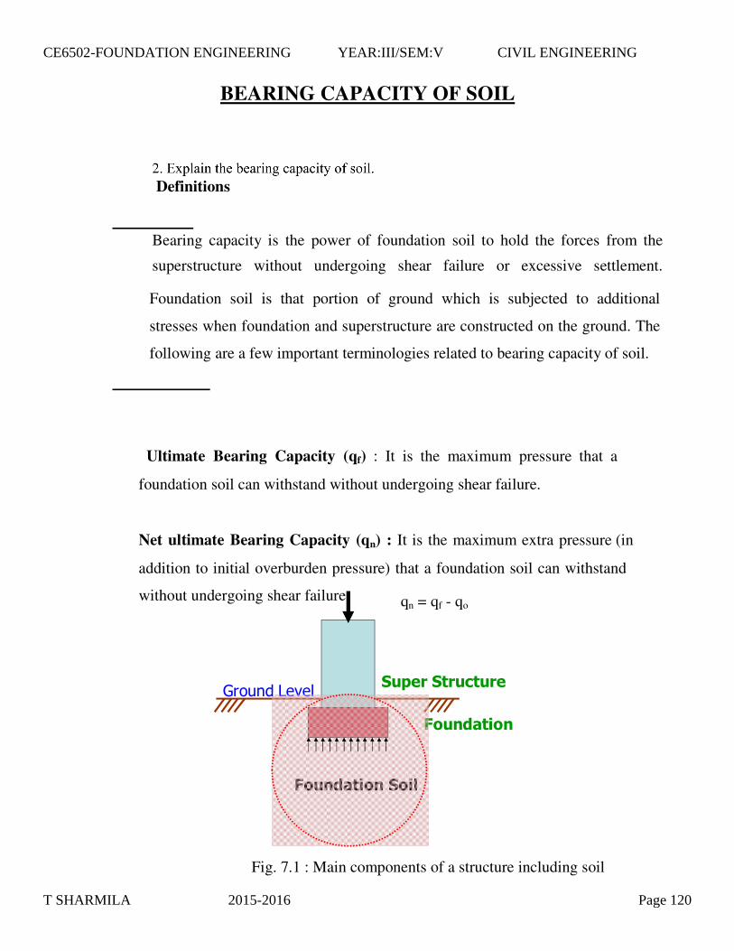
BEARING CAPACITY OF SOIL
���������������
��� ���
��� ������
���������
Foundation soil is that portion of ground which is subjected to additional
stresses when foundation and superstructure are constructed on the ground. The
following are a few important terminologies related to bearing capacity of soil.
Fig. 7.1 : Main components of a structure including soil
Definitions
Bearing capacity is the power of foundation soil to hold the forces from the
superstructure without undergoing shear failure or excessive settlement.
Ultimate Bearing Capacity (qf) : It is the maximum pressure that a
foundation soil can withstand without undergoing shear failure.
Net ultimate Bearing Capacity (qn) : It is the maximum extra pressure (in
addition to initial overburden pressure) that a foundation soil can withstand
without undergoing shear failure. qn = qf - qo
T SHARMILA 2015-2016 Page 120
CE6502-FOUNDATION ENGINEERING YEAR:III/SEM:V CIVIL ENGINEERING

on
s qFq
q +=
Here, qo represents the overburden pressure at foundation level and is equal to
�D for level ground without surcharge where � is the unit weight of soil and D
is the depth to foundation bottom from Ground Level.
7.1.3 Safe Bearing Capacity (qs) : It is the safe extra load the foundation soil is
subjected to in addition to initial overburden pressure.
Here. F represents the factor of safety.
7.1.4 Allowable Bearing Pressure (qa) : It is the maximum pressure the
foundation soil is subjected to considering both shear failure and settlement.
7.1.5 Foundation is that part of the structure which is in direct contact with soil.
Foundation transfers the forces and moments from the super structure to the soil
below such that the stresses in soil are within permissible limits and it provides
stability against sliding and overturning to the super structure. It is a transition
between the super structure and foundation soil. The job of a geotechnical
engineer is to ensure that both foundation and soil below are safe against failure
T SHARMILA 2015-2016 Page 121
CE6502-FOUNDATION ENGINEERING YEAR:III/SEM:V CIVIL ENGINEERING
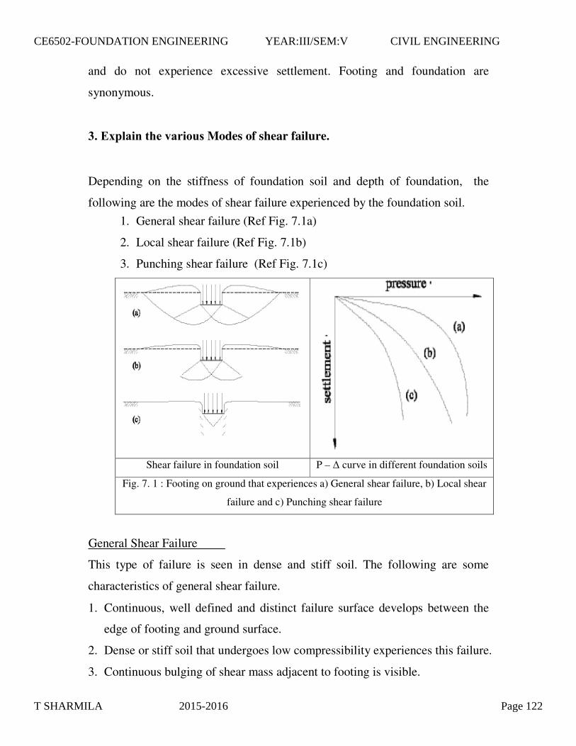
1. General shear failure (Ref Fig. 7.1a)
2. Local shear failure (Ref Fig. 7.1b)
3. Punching shear failure (Ref Fig. 7.1c)
Shear failure in foundation soil P – � curve in different foundation soils
Fig. 7. 1 : Footing on ground that experiences a) General shear failure, b) Local shear
failure and c) Punching shear failure
edge of footing and ground surface.
2. Dense or stiff soil that undergoes low compressibility experiences this failure.
3. Continuous bulging of shear mass adjacent to footing is visible.
and do not experience excessive settlement. Footing and foundation are
synonymous.
3. Explain the various Modes of shear failure.
Depending on the stiffness of foundation soil and depth of foundation, the
following are the modes of shear failure experienced by the foundation soil.
General Shear Failure
This type of failure is seen in dense and stiff soil. The following are some
characteristics of general shear failure.
1. Continuous, well defined and distinct failure surface develops between the
T SHARMILA 2015-2016 Page 122
CE6502-FOUNDATION ENGINEERING YEAR:III/SEM:V CIVIL ENGINEERING
4. Failure is accompanied by tilting of footing.
5. Failure is sudden and catastrophic with pronounced peak in P – � curve.
6. The length of disturbance beyond the edge of footing is large.
7. State of plastic equilibrium is reached initially at the footing edge and
spreads gradually downwards and outwards.
8. General shear failure is accompanied by low strain (<5%) in a soil with
considerable � (�>36o) and large N (N > 30) having high relative density
(ID > 70%).
of plastic equilibrium is observed.
2. Failure is not sudden and there is no tilting of footing.
3. Failure surface does not reach the ground surface and slight bulging of soil
around the footing is observed.
4. Failure surface is not well defined.
5. Failure is characterized by considerable settlement.
6. Well defined peak is absent in P – � curve.
7. Local shear failure is accompanied by large strain (> 10 to 20%) in a soil
with considerably low � (�<28o) and low N (N < 5) having low relative
density (ID > 20%).
Local Shear Failure
This type of failure is seen in relatively loose and soft soil. The following are
some characteristics of general shear failure.
1. A significant compression of soil below the footing and partial development
Punching Shear Failure
This type of failure is seen in loose and soft soil and at deeper elevations. The
following are some characteristics of general shear failure.
1. This type of failure occurs in a soil of very high compressibility.
2. Failure pattern is not observed.
T SHARMILA 2015-2016 Page 123
CE6502-FOUNDATION ENGINEERING YEAR:III/SEM:V CIVIL ENGINEERING
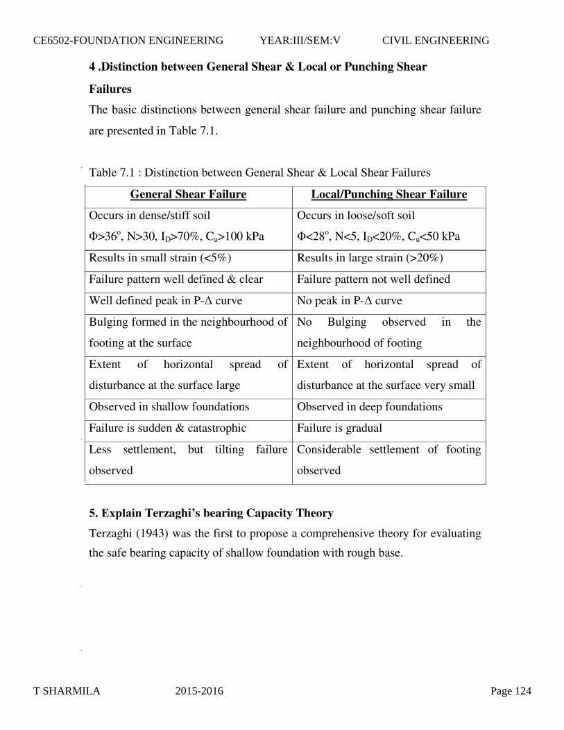
Failures
The basic distinctions between general shear failure and punching shear failure
are presented in Table 7.1.
Table 7.1 : Distinction between General Shear & Local Shear Failures
General Shear Failure Local/Punching Shear Failure
Occurs in dense/stiff soil
�>36o, N>30, ID>70%, Cu>100 kPa
Occurs in loose/soft soil
�<28o, N<5, ID<20%, Cu<50 kPa
4 .Distinction between General Shear & Local or Punching Shear
Results in small strain (<5%) Results in large strain (>20%)
Failure pattern well defined & clear Failure pattern not well defined
Well defined peak in P-� curve No peak in P-� curve
Bulging formed in the neighbourhood of
footing at the surface
No Bulging observed in the
neighbourhood of footing
Extent of horizontal spread of
disturbance at the surface large
Extent of horizontal spread of
disturbance at the surface very small
Observed in shallow foundations Observed in deep foundations
Failure is sudden & catastrophic Failure is gradual
Less settlement, but tilting failure
observed
Considerable settlement of footing
observed
5. Explain Terzaghi’s bearing Capacity Theory
Terzaghi (1943) was the first to propose a comprehensive theory for evaluating
the safe bearing capacity of shallow foundation with rough base.
T SHARMILA 2015-2016 Page 124
CE6502-FOUNDATION ENGINEERING YEAR:III/SEM:V CIVIL ENGINEERING

dimensional plane strain problem.
4. Elastic zone has straight boundaries inclined at an angle equal to � to the
horizontal.
5. Failure zone is not extended above, beyond the base of the footing. Shear
resistance of soil above the base of footing is neglected.
6. Method of superposition is valid.
7. Passive pressure force has three components (PPC produced by cohesion, PPq
produced by surcharge and PP� produced by weight of shear zone).
8. Effect of water table is neglected.
Assumptions
1. Soil is homogeneous and Isotropic.
2. The shear strength of soil is represented by Mohr Coulombs Criteria.
3. The footing is of strip footing type with rough base. It is essentially a two
9. Footing carries concentric and vertical loads.
10. Footing and ground are horizontal.
11. Limit equilibrium is reached simultaneously at all points. Complete shear
failure is mobilized at all points at the same time.
12.
plastic zone may not develop at the assumed �.
3. All points need not experience limit equilibrium condition at different loads.
4. Method of superstition is not acceptable in plastic conditions as the ground is
near failure zone.
The properties of foundation soil do not change during the shear failure
Limitations
1. The theory is applicable to shallow foundations
2. As the soil compresses, � increases which is not considered. Hence fully
T SHARMILA 2015-2016 Page 125
CE6502-FOUNDATION ENGINEERING YEAR:III/SEM:V CIVIL ENGINEERING

Fig. 7.3 : Terzaghi’s concept of Footing with five distinct failure zones in
foundation soil
T SHARMILA 2015-2016 Page 126
CE6502-FOUNDATION ENGINEERING YEAR:III/SEM:V CIVIL ENGINEERING
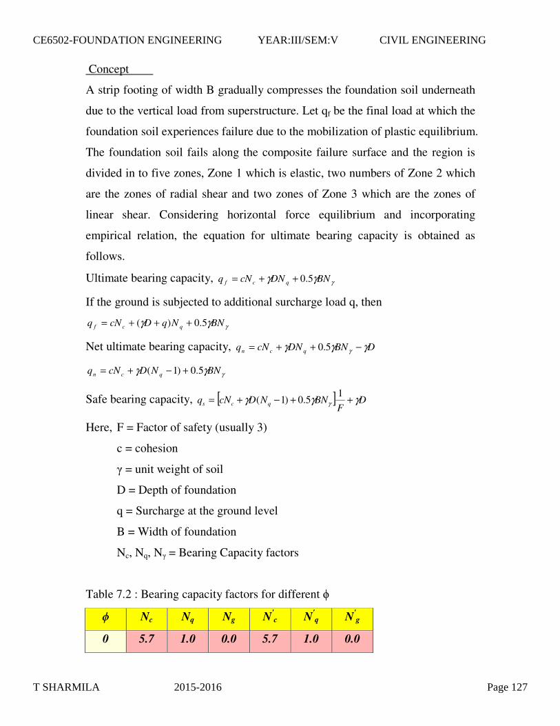
γγγ BNDNcNq qcf 5.0++=
If the ground is subjected to additional surcharge load q, then
γγγ BNNqDcNq qcf 5.0)( +++=
Net ultimate bearing capacity, DBNDNcNq qcn γγγ γ −++= 5.0
γγγ BNNDcNq qcn 5.0)1( +−+=
Safe bearing capacity, [ ] DF
BNNDcNq qcs γγγ γ ++−+= 15.0)1(
Here, F = Factor of safety (usually 3)
c = cohesion
� = unit weight of soil
D = Depth of foundation
q = Surcharge at the ground level
B = Width of foundation
Nc, Nq, N� = Bearing Capacity factors
Table 7.2 : Bearing capacity factors for different �
� Nc Nq Ng N'c N'
q N'g
0 5.7 1.0 0.0 5.7 1.0 0.0
Concept
A strip footing of width B gradually compresses the foundation soil underneath
due to the vertical load from superstructure. Let qf be the final load at which the
foundation soil experiences failure due to the mobilization of plastic equilibrium.
The foundation soil fails along the composite failure surface and the region is
divided in to five zones, Zone 1 which is elastic, two numbers of Zone 2 which
are the zones of radial shear and two zones of Zone 3 which are the zones of
linear shear. Considering horizontal force equilibrium and incorporating
empirical relation, the equation for ultimate bearing capacity is obtained as
follows.
Ultimate bearing capacity,
T SHARMILA 2015-2016 Page 127
CE6502-FOUNDATION ENGINEERING YEAR:III/SEM:V CIVIL ENGINEERING

7.4.1 Circular footing
γγγ BNDNcNq qcf 3.03.1 ++=
7.4.2 Square footing
γγγ BNDNcNq qcf 4.03.1 ++=
7.4.3 Rectangular footing
γγγ BNLB
DNcNLB
q qcf 5.0)2.01()3.01( −+++=
7.4.4 Summary of Shape factors
Table 7.2 gives the summary of shape factors suggested for strip, square,
circular and rectangular footings. B and L represent the width and length
respectively of rectangular footing such that B < L.
Table 7.3 : Shape factors for different shapes of footing
Shape sc sq s�
Strip 1 1 1
Square 1.3 1 0.8
Round 1.3 1 0.6
Rectangle )3.01(LB+ 1 )2.01(
LB−
6. Explain theEffect of shape of Foundation
The shape of footing influences the bearing capacity. Terzaghi and other
contributors have suggested the correction to the bearing capacity equation for
shapes other than strip footing based on their experimental findings. The
following are the corrections for circular, square and rectangular footings.
T SHARMILA 2015-2016 Page 128
CE6502-FOUNDATION ENGINEERING YEAR:III/SEM:V CIVIL ENGINEERING

The equation for bearing capacity explained above is applicable for soil
experiencing general shear failure. If a soil is relatively loose and soft, it fails in
local shear failure. Such a failure is accounted in bearing capacity equation by
reducing the magnitudes of strength parameters c and � as follows.
φφ tan32
tan 1 =
cc321 =
Table 7.3 summarizes the bearing capacity factors to be used under different
situations. If � is less than 36o and more than 28o, it is not sure whether the
failure is of general or local shear type. In such situations, linear interpolation
can be made and the region is called mixed zone.
Table 7.4 : Bearing capacity factors in zones of local, mixed and general shear
conditions.
Local Shear Failure Mixed Zone General Shear Failure
� < 28o 28o < � < 36o � > 36o
Nc1, Nq
1, N�1 Nc
m, Nqm, N�
m Nc, Nq, N�
7.5 Local shear failure
7.Factors influencing Bearing Capacity
Bearing capacity of soil depends on many factors. The following are some
important ones.
1. Type of soil
2. Unit weight of soil
3. Surcharge load
4. Depth of foundation
5. Mode of failure
6. Size of footing
7. Shape of footing
8. Depth of water table
9. Eccentricity in footing load
10. T SHARMILA 2015-2016 Page 129
CE6502-FOUNDATION ENGINEERING YEAR:III/SEM:V CIVIL ENGINEERING
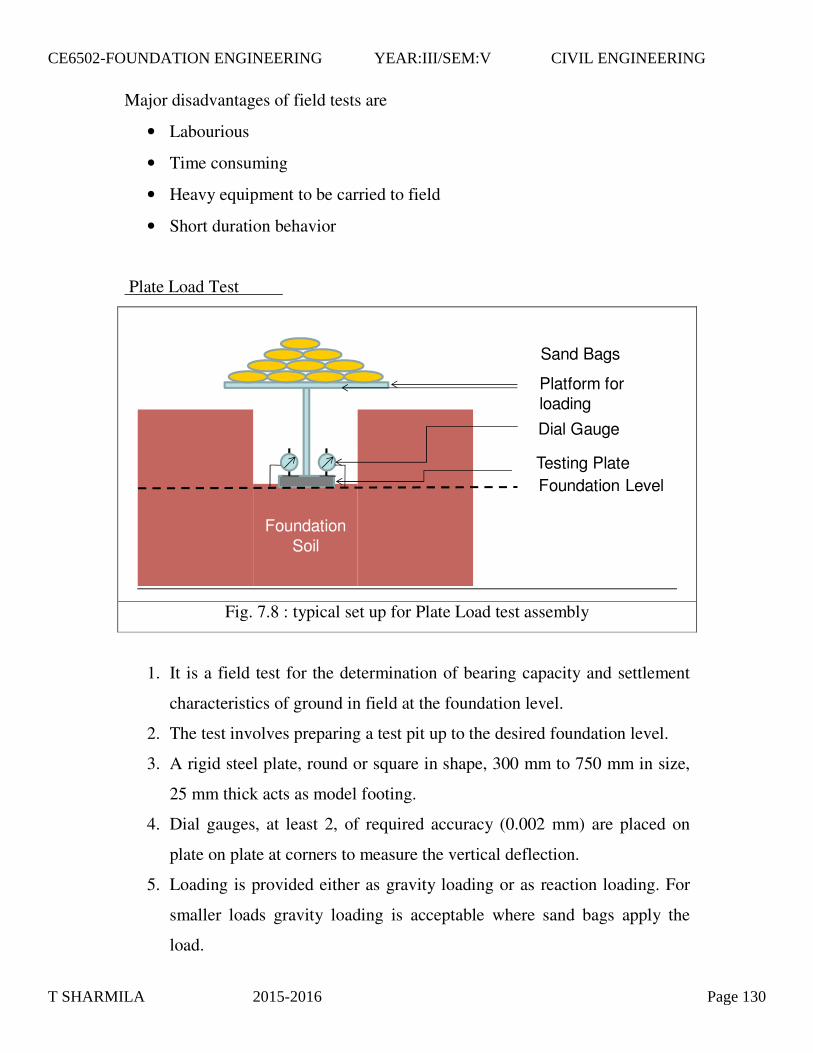
Major disadvantages of field tests are
• Labourious
• Time consuming
• Heavy equipment to be carried to field
• Short duration behavior
Foundation Soil
Sand Bags
Platform for loading
Foundation LevelTesting Plate
Dial Gauge
Fig. 7.8 : typical set up for Plate Load test assembly
1. It is a field test for the determination of bearing capacity and settlement
characteristics of ground in field at the foundation level.
2. The test involves preparing a test pit up to the desired foundation level.
3. A rigid steel plate, round or square in shape, 300 mm to 750 mm in size,
25 mm thick acts as model footing.
4. Dial gauges, at least 2, of required accuracy (0.002 mm) are placed on
plate on plate at corners to measure the vertical deflection.
5. Loading is provided either as gravity loading or as reaction loading. For
smaller loads gravity loading is acceptable where sand bags apply the
load.
Plate Load Test
T SHARMILA 2015-2016 Page 130
CE6502-FOUNDATION ENGINEERING YEAR:III/SEM:V CIVIL ENGINEERING
6. In reaction loading, a reaction truss or beam is anchored to the ground. A
hydraulic jack applies the reaction load.
7. At every applied load, the plate settles gradually. The dial gauge readings
are recorded after the settlement reduces to least count of gauge (0.002
mm) & average settlement of 2 or more gauges is recorded.
8. Load Vs settlement graph is plotted as shown. Load (P) is plotted on the
horizontal scale and settlement (�) is plotted on the vertical scale.
9. Red curve indicates the general shear failure & the blue one indicates the
local or punching shear failure.
10. The maximum load at which the shear failure occurs gives the ultimate
bearing capacity of soil.
Reference can be made to IS 1888 - 1982.
The advantages of Plate Load Test are
1. It provides the allowable bearing pressure at the location considering both
shear failure and settlement.
2. Being a field test, there is no requirement of extracting soil samples.
3. The loading techniques and other arrangements for field testing are
identical to the actual conditions in the field.
4. It is a fast method of estimating ABP and P – � behaviour of ground.
The disadvantages of Plate Load Test are
1. The test results reflect the behaviour of soil below the plate (for a
distance of ~2Bp), not that of actual footing which is generally very large.
2. It is essentially a short duration test. Hence, it does not reflect the long
term consolidation settlement of clayey soil.
3. Size effect is pronounced in granular soil. Correction for size effect is
essential in such soils.
4. It is a cumbersome procedure to carry equipment, apply huge load and
carry out testing for several days in the tough field environment.
T SHARMILA 2015-2016 Page 131
CE6502-FOUNDATION ENGINEERING YEAR:III/SEM:V CIVIL ENGINEERING

7.12 Problems & Solutions
1. A square footing is to be constructed on a deep deposit of sand at a depth of
the plan dimension of footing given �sat = 20.8 kN/m3, Nc = 25, Nq = 34 and
N� =32. (Feb 2002)
Data
C = 0
F = 2.5
D = 0.9 m
RW1 = RW2 = 0.5
� = 20.8 kN/m3
Nc = 25
Nq = 34
N� = 32
[ ] DF
cN D N R BN RBP
AP
qs = = = c + γ q − W + γ γ W + γ11.3 ( 1) 1 0.4 22
∴300 = 142.272B 2 + 53.249B3
B = 1.21 m
� = 19 kN/m3
0.9 m to carry a design load of 300 kN with a factor of safety of 2.5. The
ground water table may rise to the ground level during rainy season. Design
2. What will be the net ultimate bearing capacity of sand having � = 36o and �d
= 19 kN/m3 for (i) 1.5 m strip foundation and (ii) 1.5 m X 1.5 m square
footing. The footings are placed at a depth of 1.5 m below ground level.
Assume F = 2.5. Use Terzaghi’ s equations. (Aug 2003)
� Nc Nq N�
35o 57.8 41.4 42.4
40o 95.7 81.3 100.4
By linear interpolation Nc = 65.38, Nq = 49.38, N� = 54 at � = 36o
Data
B = 1.5 m
D = 1.5 m T SHARMILA 2015-2016 Page 132
CE6502-FOUNDATION ENGINEERING YEAR:III/SEM:V CIVIL ENGINEERING
Strip Footing
γγγ BNNDcNq qcn 5.0)1( +−+=
qn = 2148.33 kPa
Square Footing
γγγ BNNDcNq qcn 4.0)1(3.1 +−+=
qn = 1994.43 kPa
3. A square footing 2.5 m X 2.5 m is built on a homogeneous bed of sand of
density 19 kN/m3 having an angle of shearing resistance of 36o. The depth of
foundation is 1.5 m below the ground surface. Calculate the safe load that
can be applied on the footing with a factor of safety of 3. Take bearing
capacity factors as Nc= 27, Nq = 30, N� = 35. (Feb 2004)
Data
C = 0
F = 3
B = 2.5 m
D = 1.5 m
� = 19 kN/m3
Nc = 27
Nq = 30
N� = 35
[ ] DF
RBNRNDcNBP
AP
q WWqcs γγγ γ ++−+=== 14.0)1(3.1 212
Safe load, P = qs*B*B = 3285.4 kN
4. A strip footing 2 m wide carries a load intensity of 400 kPa at a depth of 1.2
m in sand. The saturated unit weight of sand is 19.5 kN/m3 and unit weight
above water table is 16.8 kN/m3. If c = 0 and � = 35o, determine the factor of
safety with respect to shear failure for the following locations of water table.
a. Water table is 4 m below Ground Level
T SHARMILA 2015-2016 Page 133
CE6502-FOUNDATION ENGINEERING YEAR:III/SEM:V CIVIL ENGINEERING
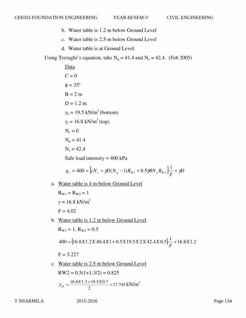
b. Water table is 1.2 m below Ground Level
c. Water table is 2.5 m below Ground Level
d. Water table is at Ground Level.
Using Terzaghi’ s equation, take Nq = 41.4 and N� = 42.4. (Feb 2005)
Data
C = 0
� = 35o
B = 2 m
D = 1.2 m
�b = 19.5 kN/m3 (bottom)
�t = 16.8 kN/m3 (top)
Nc = 0
Nq = 41.4
N� = 42.4
Safe load intensity = 400 kPa
[ ] DF
RBNRNDcNq WWqcs γγγ γ ++−+== 15.0)1(400 21
a. Water table is 4 m below Ground Level
RW1 = RW2 = 1
� = 16.8 kN/m3
F = 4.02
b. Water table is 1.2 m below Ground Level
RW1 = 1, RW2 = 0.5
[ ] 2.18.161
5.04.4225.195.014.402.18.16400 XF
XXXXXXX ++=
F = 3.227
c. Water table is 2.5 m below Ground Level
RW2 = 0.5(1+1.3/2) = 0.825
745.172
7.05.193.18.16 =+= XXeffγ kN/m3
T SHARMILA 2015-2016 Page 134
CE6502-FOUNDATION ENGINEERING YEAR:III/SEM:V CIVIL ENGINEERING

[ ] 2.18.161
825.04.422745.175.014.402.18.16400 XF
XXXXXXX ++=
F = 3.779
d. Water table is at Ground Level
RW1 = RW2 = 0.5
� = 19.5 kN/m3
[ ] 2.15.191
5.04.4225.195.05.04.402.15.19400 XF
XXXXXXX ++=
F = 2.353
5. A square footing located at a depth of 1.3 m below ground has to carry a safe
load of 800 kN. Find the size of footing if the desired factor of safety is 3.
Use Terzaghi’ s analysis for general shear failure. Take c = 8 kPa, Nc = 37.2,
Nq = 22.5, N� = 19.7. (Aug 2005)
�d = 18 kN/m3 (Assumed)
c = 8 kPa
F = 3
D = 1.3 m
Nc = 37.2
Nq = 22.5
N� = 19.7
P = 800 kN
RW1 = RW2 = 1
[ ] DF
RBNRNDcNBP
AP
q WWqcs γγγ γ ++−+=== 14.0)1(3.1 212
080006.32028.47 23 =−+ BB
B = 1.436 m
6. A square footing 2.8 m X 2.8 m is built on a homogeneous bed of sand of
density 18 kN/m3 and � = 36o. If the depth of foundation is 1.8 m, determine
T SHARMILA 2015-2016 Page 135
CE6502-FOUNDATION ENGINEERING YEAR:III/SEM:V CIVIL ENGINEERING
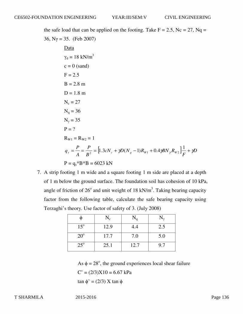
the safe load that can be applied on the footing. Take F = 2.5, Nc = 27, Nq =
36, N� = 35. (Feb 2007)
Data
�d = 18 kN/m3
c = 0 (sand)
F = 2.5
B = 2.8 m
D = 1.8 m
Nc = 27
Nq = 36
N� = 35
P = ?
RW1 = RW2 = 1
[ ] DF
RBNRNDcNBP
AP
q WWqcs γγγ γ ++−+=== 14.0)1(3.1 212
P = qs*B*B = 6023 kN
7. A strip footing 1 m wide and a square footing 1 m side are placed at a depth
of 1 m below the ground surface. The foundation soil has cohesion of 10 kPa,
angle of friction of 26o and unit weight of 18 kN/m3. Taking bearing capacity
factor from the following table, calculate the safe bearing capacity using
Terzaghi’ s theory. Use factor of safety of 3. (July 2008)
� Nc Nq N�
15o 12.9 4.4 2.5
20o 17.7 7.0 5.0
25o 25.1 12.7 9.7
As � = 28o, the ground experiences local shear failure
C’ = (2/3)X10 = 6.67 kPa
tan �’ = (2/3) X tan �
T SHARMILA 2015-2016 Page 136
CE6502-FOUNDATION ENGINEERING YEAR:III/SEM:V CIVIL ENGINEERING
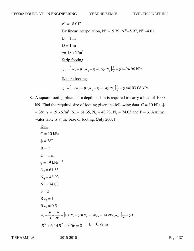
�’ = 18.01o
By linear interpolation, Nc’ =15.79, Nq’ =5.97, N�’ =4.01
B = 1 m
D = 1 m
�= 18 kN/m3
Strip footing
[ ] DF
BNNDcNq qcs γγγ γ ++−+= 15.0)1( =94.96 kPa
Square footing
[ ] DF
BNNDcNq qcs γγγ γ ++−+= 14.0)1(3.1 =103.08 kPa
8. A square footing placed at a depth of 1 m is required to carry a load of 1000
kN. Find the required size of footing given the following data. C = 10 kPa, �
= 38o, � = 19 kN/m3, Nc = 61.35, Nq = 48.93, N� = 74.03 and F = 3. Assume
water table is at the base of footing. (July 2007)
Data
C = 10 kPa
� = 38o
B = ?
D = 1 m
� = 19 kN/m3
Nc = 61.35
Nq = 48.93
N� = 74.03
F = 3
RW1 = 1
RW2 = 0.5
[ ] DF
RBNRNDcNBP
AP
q WWqcs γγγ γ ++−+=== 14.0)1(3.1 212
056.314.6 23 =−+ BB B = 0.72 m
T SHARMILA 2015-2016 Page 137
CE6502-FOUNDATION ENGINEERING YEAR:III/SEM:V CIVIL ENGINEERING

q = 2000/32 =222.22 kPa B = 3 m I� = 0.82 E = 45000 k Pa � = 0.3 SI = 0.011 m = 11 mm
Table 8.8 : Details of Load settlement for different plate sizes
Plate size (mm) Load (kN) Settlement (mm)
300 X 300 4.50 1.00
450 X 450 8.71 1.50
600 X 600 14.40 2.00
ρµ
qBIE
S I ���
����
� −=21
ρµ
qBIE
S I ���
����
� −=21
1.Determine the elastic settlement of a footing 3 m X 3 m resting on sandy soil given Es = 45000 kPa and � = 0.3. Footing carries a load of 2000 kN. Take I� = 0.82 (Feb 2002)
2.Estimate the immediate settlement of a concrete footing 1 m X 1.5 m in size, if it is founded at a depth of 1 m in silty soil whose compression modulus is 9000 kPa. Footing is expected to transmit unit pressure of 200 kPa. Assume I� = 1.06, � = 0.3 Data E = 9000 kPa � = 0.3 q = 200 kPa B = 1 m I� = 1.06 SI = 0.214 m
3.A series of plate load tests was conducted on three plates 300 mm, 450 mm and 600 mm square plates. The loads and corresponding settlements in the linear portions of P – � curves are as follows at a site. Find the immediate settlement of a footing 2 m X 2 m subjected to a load of 1000 kN.
T SHARMILA 2015-2016 Page 138
CE6502-FOUNDATION ENGINEERING YEAR:III/SEM:V CIVIL ENGINEERING
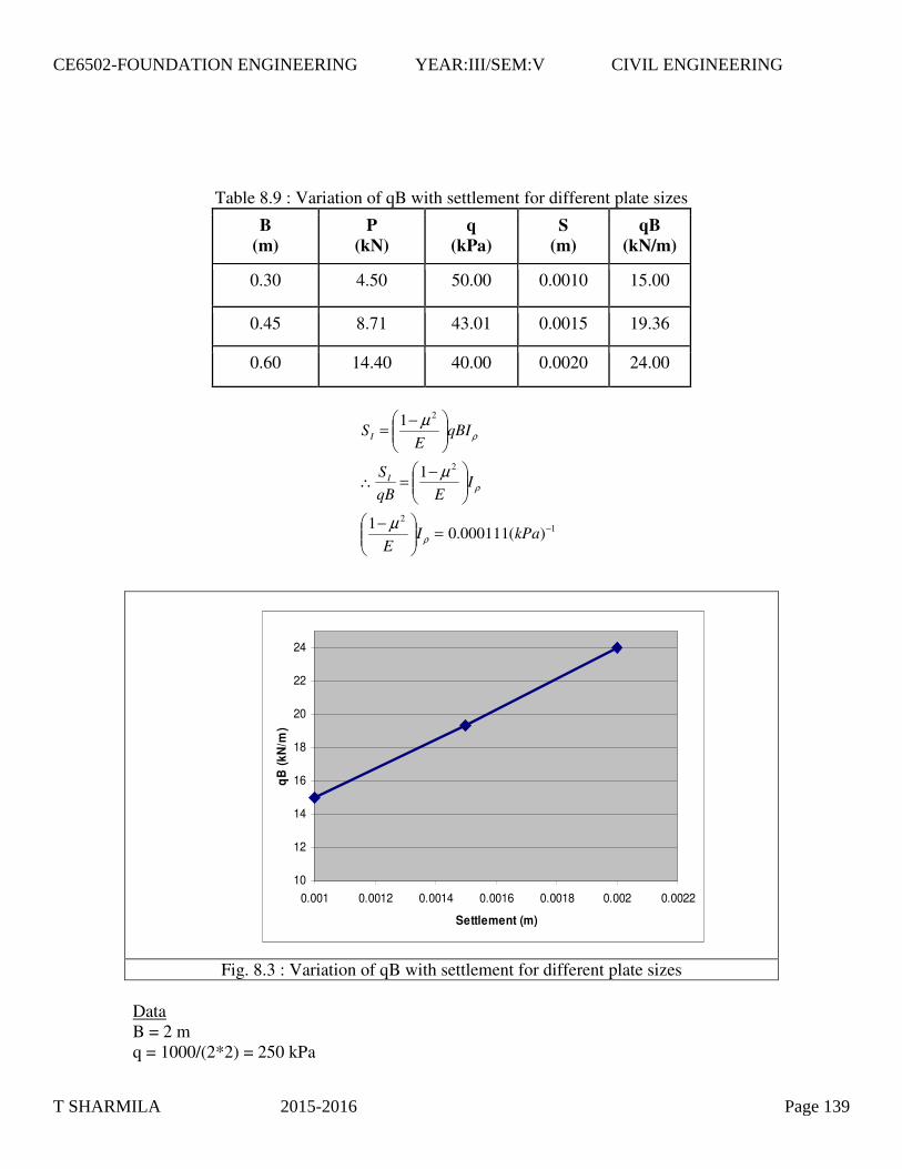
Table 8.9 : Variation of qB with settlement for different plate sizes
B (m)
P (kN)
q (kPa)
S (m)
qB (kN/m)
0.30 4.50 50.00 0.0010 15.00
0.45 8.71 43.01 0.0015 19.36
0.60 14.40 40.00 0.0020 24.00
Fig. 8.3 : Variation of qB with settlement for different plate sizes Data B = 2 m q = 1000/(2*2) = 250 kPa
12
2
2
)(000111.01
1
1
−=���
����
� −
���
����
� −=∴
���
����
� −=
kPaIE
IEqB
S
qBIE
S
I
I
ρ
ρ
ρ
µ
µ
µ
10
12
14
16
18
20
22
24
0.001 0.0012 0.0014 0.0016 0.0018 0.002 0.0022
Settlement (m)
qB (k
N/m
)
T SHARMILA 2015-2016 Page 139
CE6502-FOUNDATION ENGINEERING YEAR:III/SEM:V CIVIL ENGINEERING

SI = 0.0555 m Problem 4 The following are the results of plate load test on granular soil. Find the allowable bearing pressure if B = 2 m, Bp = 0.3 m, permissible settlement in field = 12 mm. Table 8.10 : Values of Load Settlement from Plate Load Test P (kN) 5 10 20 30 40 50 60
� (mm) 0.14 0.31 0.63 0.91 1.24 2.50 8.07
-9
-8
-7
-6
-5
-4
-3
-2
-1
00 20 40 60 80
Load (kN)
Set
tlem
ent (
mm
)
Pf = 50 kN;qf = 555.6 kPa
Fig. 8.4 : Load – Settlement curve for Plate Load Test data
qBIE
S I ��
�
����
����
� −= ρµ 21
mms
BB
BB
s
s
p
pf
fp
f
p
1
)3.03.0(2)3.02(3.0
)3.0(
)3.0(
2
2
=∴
��
�
�
++=
���
�
�
++
=
T SHARMILA 2015-2016 Page 140
CE6502-FOUNDATION ENGINEERING YEAR:III/SEM:V CIVIL ENGINEERING

Based on settlement Permissible plate settlement ~ 1 mm ABP = 32 kN/(0.3X0.3) = 355.6 kPa Problem 5 The following results were obtained from a plate load test conducted on dry sandy stratum using square plate of 0.3 m width. Determine the settlement of square footing 1.5 m wide when the intensity of loading is 120 kPa. Table 8.11 : Values of Load Settlement from Plate Load Test
Pressure (kPa) 50 100 150 200 250
Settlement (mm) 1.2 2.4 4.8 9.6 32.0
Data Sandy stratum BF = 1.5 m BP = 0.3 m SP = 3.2 mm
-35
-30
-25
-20
-15
-10
-5
00 50 100 150 200 250 300
Set
tlem
ent
(mm
)
Soil Pressure (kPa)
Plate Load Test Result
Fig. 8.5 : Load – Settlement curve for Plate Load Test data
T SHARMILA 2015-2016 Page 141
CE6502-FOUNDATION ENGINEERING YEAR:III/SEM:V CIVIL ENGINEERING

8.5 Consolidation Settlement
1. It occurs due to the process of consolidation. 2. Clay and Organic soil are most prone to consolidation settlement. 3. Consolidation is the process of reduction in volume due to expulsion
of water under an increased load. 4. It is a time related process occurring in saturated soil by draining
water from void. 5. It is often confused with Compaction. 6. Consolidation theory is required to predict both rate and magnitude of
settlement. 7. Since water flows out in any direction, the process is three
dimensional. 8. But, soil is confined laterally. Hence, vertical one dimensional
consolidation theory is acceptable. 9. Spring analogy explains consolidation settlement. 10. Permeability of soil influences consolidation.
Table 8.12 : Compaction Vs Consolidation COMPACTION CONSOLIDATION
1. Man made 2. Volume reduction due to
expulsion of air 3. Sudden (Short duration) 4. Dry density increases water
content does not change 5. Applicable for unsaturated soils
1. Natural 2. Volume reduction due to
expulsion of water 3. Gradual 4. Dry density increases water
content decreases 5. Applicable for saturated soils
mmS
S
BBBB
SS
F
F
PF
FP
F
P
89.8
)3.03.0(5.1)3.05.1(3.02.3
)3.0()3.0(
2
2
=
��
�
�
++=
��
�
�
++=
T SHARMILA 2015-2016 Page 142
CE6502-FOUNDATION ENGINEERING YEAR:III/SEM:V CIVIL ENGINEERING

Time factor is obtained from the formulae shown below. It depends on the degree of consolidation.
Commonly time factor at 50 % and 90 % degrees of consolidation are used and are as mentioned below. (TV)50 = 0.197 (TV)90 = 0.848
Problem 6 The total time taken for 50 % consolidation of clay layer is 4 years. What will be the time taken for 90 % consolidation ? (Aug 2001) (TV)50 = 0.197 (TV)90 = 0.848 Problem 7 A layer of clay 8 m thick underlies a proposed new building. The existing overburden pressure at the center of layer is 290 kPa and the load due to new building increases the pressure by 100 kPa. Cc = 0.45, � = 50 %, G = 2.71. Estimate the consolidation settlement. (Aug 2002) Data Cc = 0.45 eo = 1.355 H = 8 m �o = 290 kPa �� = 100 kPa
%)100(log9332.07813.1
1004
10UT
UT
V
V
−−=
��
�
�= π
yearst
dt
d
tdT
tdT
C VVV
22.17
4197.0848.0
)()(
90
2
90
2
50
250
90
290
=∴
=∴
==
T SHARMILA 2015-2016 Page 143
CE6502-FOUNDATION ENGINEERING YEAR:III/SEM:V CIVIL ENGINEERING

45o (Dispersion angle)
H
H/2 H/2B
Fig. 8.9 : Concept of Load dispersion
Problem 8 A normally consolidated clay layer is 18 m thick. Natural water content is 45 %, saturated unit weight is 18 kN/m3, grain specific gravity is 2.7 and liquid limit is 63 %. The vertical stress increment at the center of clay layer due to foundation load is 9 kPa. Ground water table is at the surface. Determine the settlement. (Aug 2003) Data Cc = 0.477 eo = 1.215 H = 18 m �o = 162 kPa �� = 9 kPa
���
����
� ∆+���
����
�
+=
o
o
o
cc H
eC
Sσ
σσ10log
1
355.1== Geo ω
m
He
CS
o
o
o
cc
1967.0
log1 10
=
���
����
� ∆+���
����
�
+=
σσσ
T SHARMILA 2015-2016 Page 144
CE6502-FOUNDATION ENGINEERING YEAR:III/SEM:V CIVIL ENGINEERING

Problem 9 A square footing 1.2 m X 1.2 m rests on a saturated clay layer 4 m deep. �L = 30 %, �sat = 17.8 kN/m3, � = 28 % and G = 2.68. Determine the settlement if the footing carries a load of 300 kN. Problem 10 A test on undisturbed sample of clay showed 90 % consolidation in 10 minutes. The thickness of sample was 25 mm with drainage at both top and bottom. Find the time required for 90 % consolidation of footing resting on 5
477.0%)10(009.0 =−= LCC ω
kPa
kPaZsato
9
1622
18*18
=∆
===
σ
γσ
215.1== Geo ω
m
He
CS
o
o
o
cc
091.0
log1 10
=
���
����
� ∆+���
����
�
+=
σσσ
kPa
kPaZsato
095.11)22.12(
300
6.3524
*8.17
2 =++
=∆
===
σ
γσ
mH
Ge
C
o
LC
4
75041.068.2*28.0
18.0%)10(009.0
=====−=
ωω
m
He
CS
o
o
o
cc
0485.0
log1 10
=
���
����
� ∆+���
����
�
+=
σσσ
T SHARMILA 2015-2016 Page 145
CE6502-FOUNDATION ENGINEERING YEAR:III/SEM:V CIVIL ENGINEERING

m thick compressible layer sandwiched between two sand layers. (Aug 2007) Data Dlab = 25/2 = 12.5 mm Dfield = 5000/2 = 2500 mm tlab = 10/(60*24*365) years
2
���
�
�=
field
lab
field
lab
dd
tt
yearst
dd
tt
field
field
lab
field
lab
761.0
2
=∴���
�
�=
T SHARMILA 2015-2016 Page 146
CE6502-FOUNDATION ENGINEERING YEAR:III/SEM:V CIVIL ENGINEERING
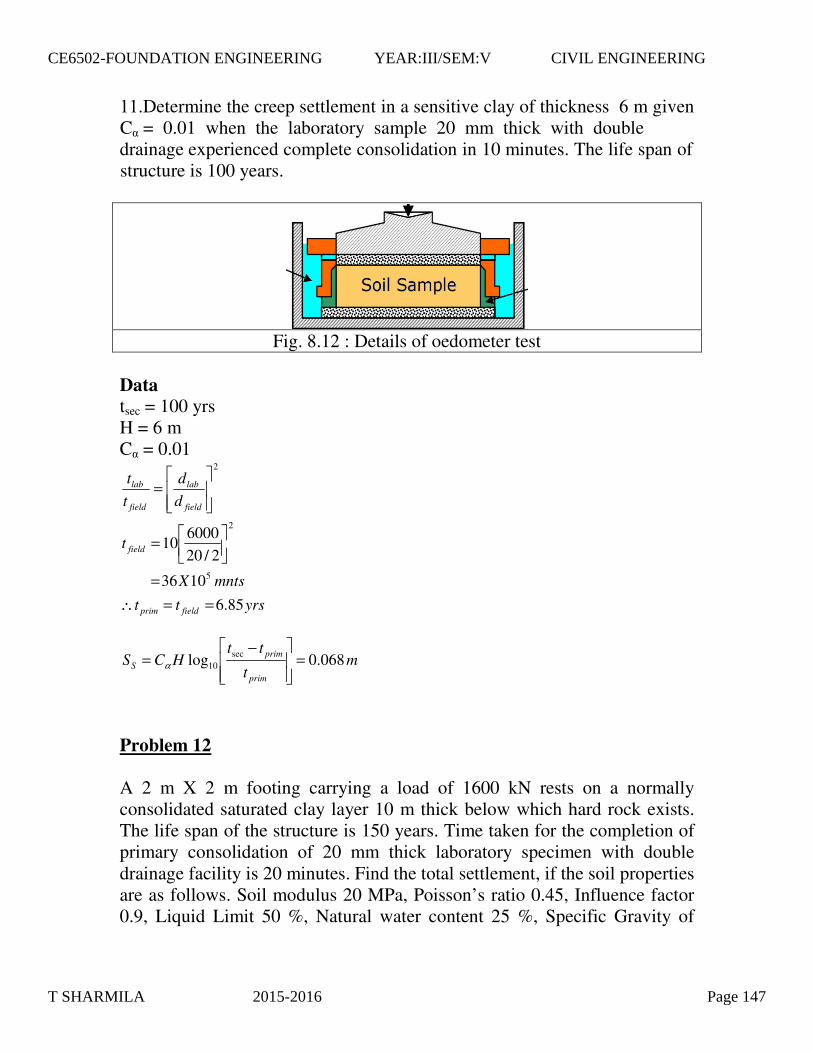
Fig. 8.12 : Details of oedometer test
Data tsec = 100 yrs H = 6 m C� = 0.01
Problem 12 A 2 m X 2 m footing carrying a load of 1600 kN rests on a normally consolidated saturated clay layer 10 m thick below which hard rock exists. The life span of the structure is 150 years. Time taken for the completion of primary consolidation of 20 mm thick laboratory specimen with double drainage facility is 20 minutes. Find the total settlement, if the soil properties are as follows. Soil modulus 20 MPa, Poisson’ s ratio 0.45, Influence factor 0.9, Liquid Limit 50 %, Natural water content 25 %, Specific Gravity of
yrstt
mntsX
t
dd
tt
fieldprim
field
field
lab
field
lab
85.61036
2/206000
10
5
2
2
==∴=
��
�
�=
���
�
�=
mt
ttHCS
prim
primS 068.0log sec
10 =���
�
� −= α
11.Determine the creep settlement in a sensitive clay of thickness 6 m given C� = 0.01 when the laboratory sample 20 mm thick with double drainage experienced complete consolidation in 10 minutes. The life span of structure is 100 years.
T SHARMILA 2015-2016 Page 147
CE6502-FOUNDATION ENGINEERING YEAR:III/SEM:V CIVIL ENGINEERING

grains 2.7, saturated density 20 kN/m3 and coefficient of secondary compression 0.001. Total Settlement, S = SI + SC + SS Data for Immediate Settlement E = 20000 kPa � = 0.45 q = 1600/22 = 400 kPa B = 2 m I� = 0.9 Data for Consolidation Settlement �L = 50 % � = 25 % G = 2.7 Cc = 0.36 eo = 0.675 H = 10 m �o = 100 kPa �� = 11.11 kPa
ρµ
qBIE
S I ���
����
� −=21
mmmS I 71.2802871.0 ==
675.01
7.2*25.0
36.0%)10(009.0
===
=−=
SG
e
C
o
LC
ωω
kPaH
sato 1002
== γσ
kPa
BH
P11.11
22
2 =
��
���
� +=∆σ
���
����
� ∆+���
����
�
+=
o
o
o
cc H
eC
Sσ
σσ10log
1
T SHARMILA 2015-2016 Page 148
CE6502-FOUNDATION ENGINEERING YEAR:III/SEM:V CIVIL ENGINEERING

Data for Secondary Settlement tsec = 150 yrs H = dfield = 10 m C� = 0.001 dlab = 10 mm tlab = 20 mnts Total Settlement, S = SI + SC + SS
= 28.71 + 98.30 + 4.70 =131.71 mm 8.7 Factors Influencing Settlement Many factors influence the settlement of foundation soil when a structure is built on it. The following are a few important factors to be considered in the evaluation of settlement.
1. Elastic properties of soil 2. Shape of footing 3. Rigidity of footing 4. Contact pressure 5. Width of footing 6. Compressibility characteristics of soil 7. Initial conditions of soil (Density, void ratio etc.) 8. Degree of saturation 9. Over Consolidation Ratio 10. Time available for settlement 11. Thickness of soil layer
yrstt
dd
tt
fieldprim
field
lab
field
lab
05.38
2
==∴���
�
�=
���
�
� −=
prim
primS t
ttHCS sec
10logα
mmm 7.40047.0 ==
T SHARMILA 2015-2016 Page 149
CE6502-FOUNDATION ENGINEERING YEAR:III/SEM:V CIVIL ENGINEERING

𝑞𝑞 = 𝑄𝑄𝐴𝐴− 𝛾𝛾𝐷𝐷𝑓𝑓 [5.16]
Where
𝑄𝑄 = dead weight of the structure and the live load
𝐴𝐴 = area of the raft
In all cases, q should be less than or equal to 𝑞𝑞all (net ).
Example 1
Determine the net ultimate bearing capacity of a mat foundation measuring 45 ft × 30 ft on saturated clay with 𝑐𝑐𝑢𝑢 = 1950 lb/ft2, 𝜙𝜙 = 0, and 𝐷𝐷𝑓𝑓 = 6.5 ft.
Solution
From equation (10)
𝑞𝑞net (u) = 5.14𝑐𝑐𝑢𝑢 �1 + �0.195𝐵𝐵𝐿𝐿
�� �1 + 0.4 𝐷𝐷𝑓𝑓𝐵𝐵�
= (5.14)(1950) �1 + �0.195×3045
�� �1 + �0.4×6.530
��
= 12,307 lb/ft2
Example 2
What will the net allowable bearing capacity of a mat foundation with dimensions be of 45 ft × 30 ft constructed over a sand deposit? Here, 𝐷𝐷𝑓𝑓 = 6 ft, allowable settlement = 1 in., and corrected average penetration number 𝑐𝑐𝑐𝑐𝑐𝑐𝑐𝑐 = 10.
Solution
From equation (13)
𝑞𝑞all (net ) = 0.25𝑐𝑐𝑐𝑐𝑐𝑐𝑐𝑐 �1 + 0.33𝐷𝐷𝑓𝑓𝐵𝐵
� 𝐹𝐹𝑒𝑒 ≤ 0.33𝑐𝑐𝑐𝑐𝑐𝑐𝑐𝑐 𝐹𝐹𝑒𝑒
𝑞𝑞all (net ) = 0.25(10) �1 + 0.33(6)30
� (1) ≈ 2.67kip/ft2
DIFFERENTIAL SETTLEMENT OF MATS
T SHARMILA 2015-2016 Page 150
CE6502-FOUNDATION ENGINEERING YEAR:III/SEM:V CIVIL ENGINEERING

A foundation is a integral part of the structure which transfer the load of the superstructure to the soil. Afoundation is that member which provides support for the structure and it's loads. It includes the soil androck of earth's crust and any special part of structure that serves to transmit the load into the rock or soil.The different types of the foundations are given in fig. 4.1
Different types of footings
Fig. 4.1 Different types of footings
If the soil conditions immediately below the structure are sufficiently strong and capable of supporting therequired load, then shallow spread footings can be used to transmit the load. On the other hand, if the soilconditions are weak, then piles or piers are used to carry the loads into deeper, more suitable soil.
Design Considerations:
Must not settle excessively.
Must be placed at depth sufficient to prevent damage from surface environmental effects (frost, swelling andshrinkage, erosion and scour).
Must not cause failure of supporting soil (Bearing Capacity criteria).
1 Introduction
T SHARMILA 2015-2016 Page 151
CE6502-FOUNDATION ENGINEERING YEAR:III/SEM:V CIVIL ENGINEERING

Advantages of using shallow foundation
Cost (affordable)
Construction Procedure (simple)
Materials (mostly concrete)
Labor (does not need expertise)
Disadvantages of using shallow foundation
Settlement
Irregular ground surface (slope, retaining wall)
Foundation subjected to pullout, torsion, moment.
Shallow foundations are foundations where the depth of the footing ( ) is generally less than the width (B)
of the footing. Deep foundations are foundations where the depth of the footing ( ) is greater than the
width (B) of the footing.
Footings :
It is circular, square or rectangular slab of uniform thickness. Sometimes, it is stepped or haunched to spreadthe load over a larger area. When spread footing is provided to support an individual column, it is called“Isolated footing” as shown in fig.4.2.
1. Spread Footing:
Fig. 4.2 Isolated (spread) footing
T SHARMILA 2015-2016 Page 152
CE6502-FOUNDATION ENGINEERING YEAR:III/SEM:V CIVIL ENGINEERING
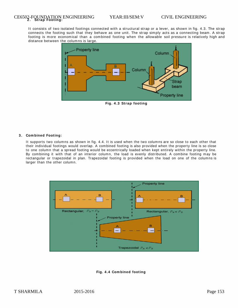
2. Strap Footing:
It consists of two isolated footings connected with a structural strap or a lever, as shown in fig. 4.3. The strapconnects the footing such that they behave as one unit. The strap simply acts as a connecting beam. A strapfooting is more economical than a combined footing when the allowable soil pressure is relatively high anddistance between the columns is large.
Fig. 4.3 Strap footing
3. Combined Footing:
It supports two columns as shown in fig. 4.4. It is used when the two columns are so close to each other thattheir individual footings would overlap. A combined footing is also provided when the property line is so closeto one column that a spread footing would be eccentrically loaded when kept entirely within the property line.By combining it with that of an interior column, the load is evenly distributed. A combine footing may berectangular or trapezoidal in plan. Trapezoidal footing is provided when the load on one of the columns islarger than the other column.
Fig. 4.4 Combined footing
T SHARMILA 2015-2016 Page 153
CE6502-FOUNDATION ENGINEERING YEAR:III/SEM:V CIVIL ENGINEERING

4. Strip/continuous footings
A strip footing is another type of spread footing which is provided for a load bearing wall. A strip footing canalso be provided for a row of columns which are so closely spaced that their spread footings overlap or nearlytouch each other. In such a cases, it is more economical to provide a strip footing than to provide a numberof spread footings in one line. A strip footing is also known as “continuous footing”. Refer fig. 4.5
Fig. 4.5 Strip footing
It is a large slab supporting a number of columns and walls under entire structure or a large part of thestructure. A mat is required when the allowable soil pressure is low or where the columns and walls are soclose that individual footings would overlap or nearly touch each other. Mat foundations are useful in reducingthe differential settlements on non-homogeneous soils or where there is large variation in the loads onindividual columns. In this there are two types:
4. Mat or Raft footings:
Fig. 4.6 Typical Raft Foundation
T SHARMILA 2015-2016 Page 154
CE6502-FOUNDATION ENGINEERING YEAR:III/SEM:V CIVIL ENGINEERING

used to build pile foundations, which are deep and which cost more than shallow foundations (chapters 3 and 4). Despite the cost, the use of piles often is necessary to ensure structural safety. The following list identifies some of the conditions that require pile foundations (Vesic, 1977).
1. When the upper soil layer(s) is (are) highly compressible and too weak to support the load transmitted by the superstructure, piles are used to transmit the load to underlying bedrocks or a stronger soil layer, as shown in figure 8.1a. When bedrock is not encountered at a reasonable depth below the ground surface, piles are used to transmit the structural load to the soil gradually. The resistance to the applied structural load is derived mainly from the frictional resistance developed at the soil-pile interface (figure 8. 1b).
Figure 8.1 Conditions for use of pile foundations
UNIT IV
1.EXPLAIN THE TYPES OF PILES.
Piles are structural members that are made of steel, concrete, and/or timber. They are
T SHARMILA 2015-2016 Page 155
CE6502-FOUNDATION ENGINEERING YEAR:III/SEM:V CIVIL ENGINEERING

Selecting the type of pile to be used and estimating its necessary length are fairly difficult tasks that require good judgment. In addition to the classification given in section 2, piles can be divided into three major categories, depending on their lengths and the mechanisms of load transfer to the soil: (a) point bearing piles, (b) friction piles, and (c) compaction piles.
Point Bearing Piles
If soil-boring records establish the presence of bedrocks or rocklike material at a site within a reasonable depth, piles can be extended to the rock surface. (Figure 8.6a). In this case, the ultimate capacity of the piles depends entirely on the load bearing capacity of the underlying material; thus the piles are called point bearing piles. In most of these cases, the necessary length of the pile can be fairly well established.
Figure 8.6 (a) and (b) Point bearing piles; (c) friction piles
2. ESTIMATING PILE LENGTH
T SHARMILA 2015-2016 Page 156
CE6502-FOUNDATION ENGINEERING YEAR:III/SEM:V CIVIL ENGINEERING
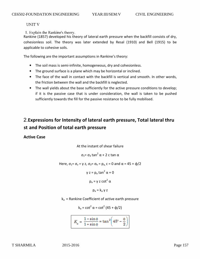
�������+24-50� ������� ��������������������������������� ������������������������� ����
������������ ������ ��� ����� � ��� ����� ���� � � ��� ����� +292,0� �� � :���� +292-0� �� ���
����������������������������
��������� �������������������������������� ������&������;�
• ��������������������"��������������������� ����� ��������������
• �������� ��������������������� �������������/��������������� ��
• �������������� ���� ���������� ������������� ������������� �������(������� �� ���
������������� ������� ������ ���������������������� ��
• ���� �������� �������������������������������������������������� �������� ������#�
��� �� ��� �� �������� ����� �� ��� �� ��� ����� �������� �� � ���� ��� ����� �� ��� ���� �
�������������� �� ���������������������������������������������������� ��
�
�(�� �������
)�������������������������
<2=�<>���1�?�@�1������?�
A�����<2=�<��=�B�/��<>=�<�=�������=�,��� �?�=�C-�@��D1�
B�/�=������1�?�@�,�
���=�B�/���1�?�
���=����B�/�
����=� �������6��������������������������������
���=���1�?�=���
1�+C-�@��D10�
�
2.�%����������!�����������&��!�����������������������'������������������������������������!����������������������
T SHARMILA 2015-2016 Page 157
CE6502-FOUNDATION ENGINEERING YEAR:III/SEM:V CIVIL ENGINEERING

����������������������������������������� ����E�=�+2D10�+���B�A0�+A0�
�
F ����������������������������)*����� ���������
����� �������
A�����<2=�<�=�����<>=�<��=�B�/����=�,��� �?�=�C-�@��D1�
���=�B�/���1�?�@�,�
���=�B�/���1�?�
���=����B�/�
����=� �������6����������������������������������
���=���1�?�=���
1�+C-�@��D10�
�
������������������������������������������� ����E�=�+2D10�+���B�A0�+A0�
�
F ���������������������������AD>����� ���������
� �
T SHARMILA 2015-2016 Page 158
CE6502-FOUNDATION ENGINEERING YEAR:III/SEM:V CIVIL ENGINEERING
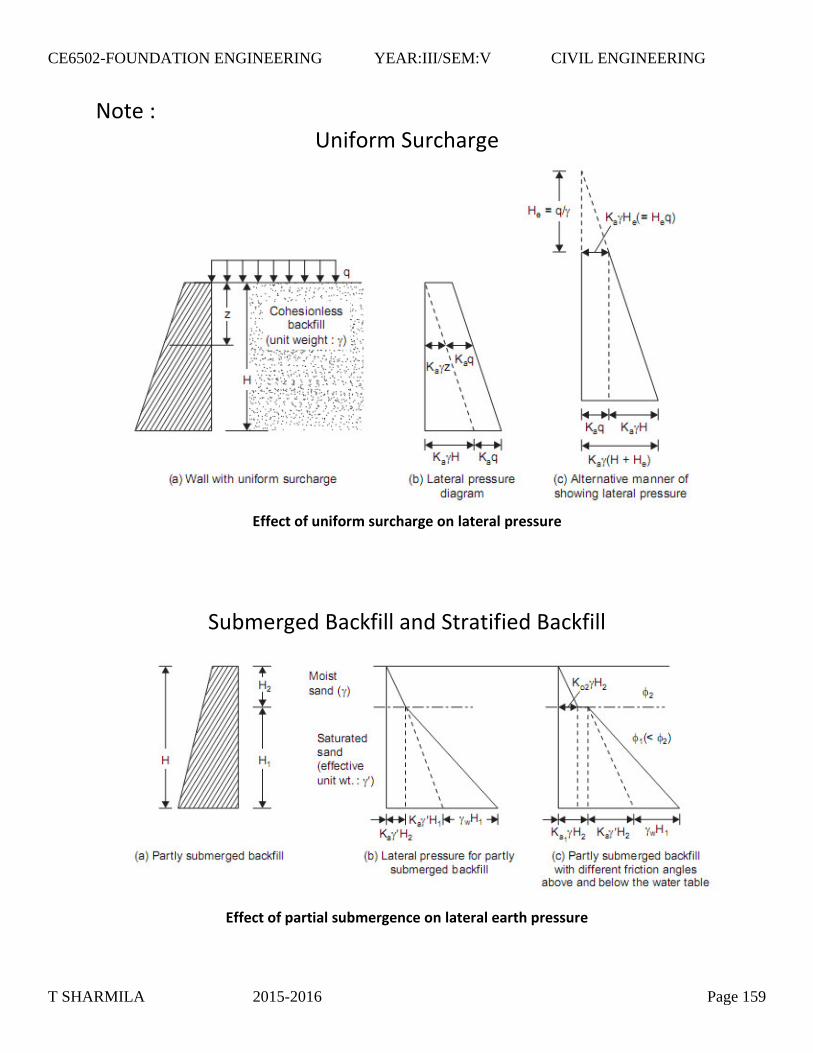
'���;�
G ������ ����������
��!!�(���!����!��� ����(���+����������������������
�
���� ���� �:���������� �������� �:��������
�
�!!�(���!������������� ��+��(����������������������������
�
T SHARMILA 2015-2016 Page 159
CE6502-FOUNDATION ENGINEERING YEAR:III/SEM:V CIVIL ENGINEERING
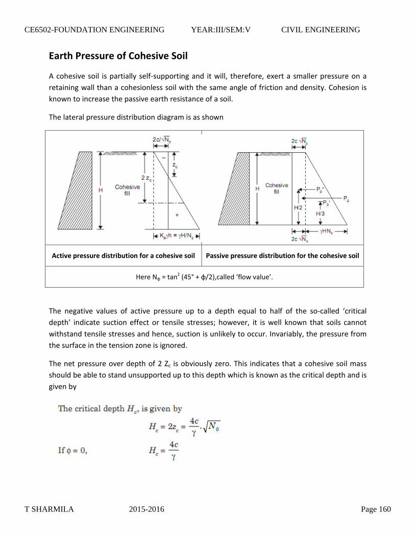
����������������!������� ������
)������������������������������"������������ ���� ����������������������� ��������������������
���������� ��������������������������� ������� ��������������������� � �������6����������
���� ������������������������������������������������
������������������� ���������� ������ ���������� ��
�
�(�� ������������������������!�����(����� ������� ����� ������������������������!�������(����� �������
A����' I�=���1�+C-J�@�ID10������ �%���� ������&��
�
��� �������� ������� ��� ������ ��������� ��� �� �� ��� ������ �� ���� ��� �� ��"����� � %��������
��&� �� ����� ������������� ���������� �������#� �� ������ �� ��� � ���� ���� �� �� ������ ������
� ���� ������������������ �����������������������������������(�������������������������� �
����������������������/������������� ��
�������������������� ������1�K���������������/����������� ������������������������ ����
���� �������������� ���������� ��������� ���� ���������� ��������������� ����� ����
���������
�
� �
T SHARMILA 2015-2016 Page 160
CE6502-FOUNDATION ENGINEERING YEAR:III/SEM:V CIVIL ENGINEERING

6������ )�������� 6����� �� +25530�� �� ��� ���� $����� �������� �� �� ������� ���������� � ��� ��
����������������������������������������/���� ����������� �������������������� ������� ����
������������������������ ������
6����� �&������������ ��������������� ���� ���������� ��������� �������������� ��������
������(����� ������������������������������� ������������������������� �������� �� �� �������
��������������������������� ���������(������������������������������ ���������� ���������
� ��� ����� �� ������������������������ ��� � ���������� �� ������� ������� ������ ���
��������������������������������� ��������������� �������������������������� �������������
� �������������� ��������%��� ����� � ��&��(����������� ������������������� ����� ������ �����
��� ��� ���������� ��������� ����� � ���� ��� ����� �� �� �� �� ���������������������������
����������������������� ����� � ����������������������� ��������������������� ����������
�������������� ���������������� ������� ������� ���� ������ ������� ��������� �������
��������������� ��6����� �&�������������������� ���%F � �������&���� ���������������������
�� ������ ������� ��������� A�� ������ 6����� �� �������/� � �� ����������� ��� �� ��������� ��� ��
����� ������������������������������ ��� ����������������� ��������������� ��� ������
��� �������� (�� ����� �� ��� ��� � �������� � �� �� ����� ����� ��� �� ������ ������� ��������
���� ��������������������������� ���� ���������������������������������������� ��������
�������������������������������� �� ������ ����������� �����
(���������������� ��6����� �&��������� ��� ������ ��������������� ���� � ������� �����
����������������� ���������������������������� �������������� �������������� ����������
���� �������� ����� � � ����� E������� +24C,0�� 6��� ���� +24330�� ������ +24520� �� � H��������
+244,0����������������������� ���������� ��������� ������� ������6����� �&��������
�������������������6����� �&��� ����� �������������/� �������������������� �����������
��������� ����� �������� ��� ���� ���������� ������ � �� �� ��� � ���������� �� � ���� ����� ��� � ���� �
������ �������� ������������������� ������
����� �������
������� ��������� ���������6����� �&��� � ��������������������� �;�
� ������������������������� ��� ������ ������ ����������� ���������#�������������������"
����� ����� ��� ����������� ��������� � �������� ����������� �������� �������� ��� ���
���������
� � , -#�. ��/����� �$�
T SHARMILA 2015-2016 Page 161
CE6502-FOUNDATION ENGINEERING YEAR:III/SEM:V CIVIL ENGINEERING

• �������������������������� � �����������������������������������������������������(�
������������������������ �����(����������������������������������� ��� �������
���� ����6����� ���
• ������ ����� � ���������������� ��� ���� ������������������������������� ����
����� �������������������� ��
• ������������� � ������������������������������ � ���������� ��������������
���������������� ����������������"�� ���������������� ��������������������
��� ������ �� ��������������L��� �������� ����������������������� ���������������
�������������������� ������� ������ ����������������� ����������������� �%� �����������&��
• ���������� ���� ���� ������������������������ ����������������� �" �� ���������
�������� %�����������&������������������������������ ������������ � ��������� �����
������� �������� ������������ ������ ��������� ������������������������������ �����
���������������������� ���������� ������������������������������������ ��� ��
• F ����������� � ��������������������������������� ���������� � �������� ��� �������
������������ ����� �������������������������������������� ����������+�������� �
�������0����� �������� ������������� ��
���� ������������������� ������������������������������������ �;�
• ������������ ������������������������I��� �������/������� ������������� ���� �����
������������ ��������������������� �������������� �������������������#���������������
�����������������������������
• (����� �������� ���� ������������������������������������������������ � ��������������
���� ��� ���� ��� �� ����� � ����� (���� ������ ������ �� ����� � � ��� ��� ��� �� �� ���� �� �
�� �� �� ����������������������������������������������������������� �����(����
����� ��� �������� ���� ����������� �� ����� � � ��� ��� ��� �� �� ���� �� � ��� �� � ��� ��
��������������� ��������������������� ��������������������
• $������������������� ������������ ��������� ���������� ����������������� ������ ���
������' �� ��&����� ���� ��������������� �+������������������� ������ ������� � �����
�������� ��� �� ����������� ��� �������� �� ��� �� ���� ��� ������ ������ ��� �� �����0�� ����
������ ��� ��������� � ���� ������ ��� �� ����������� ��� ��������� ��� ���� ��� ����� ��
������������������������ ��������������� ��
• �������������� ������� �������� ������������������������
• ������������������� ����������������
�
T SHARMILA 2015-2016 Page 162
CE6502-FOUNDATION ENGINEERING YEAR:III/SEM:V CIVIL ENGINEERING

Gravity retaining walls (figure 7.1a) are constructed with plain concrete or stone masonry. They depend on their own weight and any soil resting on the masonry for stability. This type of construction is not economical for high walls.
Figure 7.1 Types of retaining wall
In many cases, a small amount of steel may be used for the construction of gravity walls, thereby minimizing the size of wall sections. Such walls are generally referred to as semigravity walls (figure 7.1b).
Cantilever retaining walls (figure 7.1c) are made of reinforced concrete that consists of a thin stem and a base slab. This type of wall is economical to a height of about 25 ft (8 m).
Counterfort retaining walls (figure 7.1d) are similar to cantilever walls. At regular intervals, however, they have thin vertical concrete slabs known as counterforts that tie the wall and the base slab together. The purpose of the counterforts is to reduce the shear and the bending moments.
To design retaining walls properly, an engineer must know the basic soil parameters-that is, the unit weight, angle of friction, and cohesion-for the soil retained behind the wall and the soil below the base slab. Knowing the properties of the soil behind the wall enables the engineer to determine the lateral pressure distribution that has to be designed for.
There are two phases in the design of conventional retaining walls. First, with the lateral earth pressure known, the structure as a whole is checked for stability. That includes checking for possible overturning, sliding, and bearing capacity failures.
T SHARMILA 2015-2016 Page 163
CE6502-FOUNDATION ENGINEERING YEAR:III/SEM:V CIVIL ENGINEERING

Second, each component of the structure is checked for adequate strength, and the steel reinforcement of each component is determined.
This chapter presents the procedures for determining retaining wall stability. Checks for adequate strength of each component of the structures can be found in any textbook on reinforced concrete.
Mechanically stabilized retaining walls have their backfills stabilized by inclusion of reinforcing elements such as metal strips, bars, welded wire mats, geotextiles, and geogrids. These walls are relatively flexible and can sustain large horizontal and vertical displacement without much damage.
In this chapter the gravity and cantilever retaining walls will be described first, followed by mechanically stabilized walls with metal strips, geotextiles, and geogrids reinforced backfills.
GRAVITY AND CANTILEVER WALLS
PROPORTIONING RETAINING WALLS
When designing retaining walls, an engineer must assume some of the dimensions, called proportioning, which allows the engineer to check trial sections for stability. If the stability checks yield undesirable results, the sections can be changed and rechecked. Figure 7. 2 shows the general proportions of various retaining walls components that can be used for initial checks.
Figure 7.2 Approximate dimensions for various components of retaining wall for initial stability checks: (a) gravity wall; (b) cantilever wall [note: minimum dimension of 𝐷𝐷 is 2 ft (≈ 0.6 m)]
T SHARMILA 2015-2016 Page 164
CE6502-FOUNDATION ENGINEERING YEAR:III/SEM:V CIVIL ENGINEERING

Distribution steel: 0.12% Gross area for HYSD bars, 0.15% for Mild steel bars
Temperature steel: Provide this steel at the outer face which is same as the distribution steel.
Also provide suitable development lengths for all steel meeting at the junction. Providesuitable construction keys, drainage facilities, tile drains and weep holes as shown in thedrawing. Sketch the drawings and detail as per the requirements.
Retaining wall Design
Design example-1
Design a cantilever retaining wall (T type) to retain earth for a height of 4m. the backfill ishorizontal. The density of soil is 18kN/m3. Safe bearing capacity of soil is 200 kN/m2. Takethe co-efficient of friction between concrete and soil as 0.6. The angle of repose is 30 degrees.Use M20 concrete and Fe415 steel.
Solution
Data: h' = 4m, SBC= 200 kN/m2, γ= 18 kN/m3, μ=0.6, φ=30°
To fix the height of retaining wall, HH= h' +Df
Depth of foundation
Rankine’s formula: Df =2
sin1sin1
SBC
= 2ak
γSBC
Ast
ProvidedAst/2
Ast
DistanceFromtop
h2
Every alternate barcurtailed
Ast
Ast/2 h2
Ldt
h1c
h1
T SHARMILA 2015-2016 Page 165
CE6502-FOUNDATION ENGINEERING YEAR:III/SEM:V CIVIL ENGINEERING
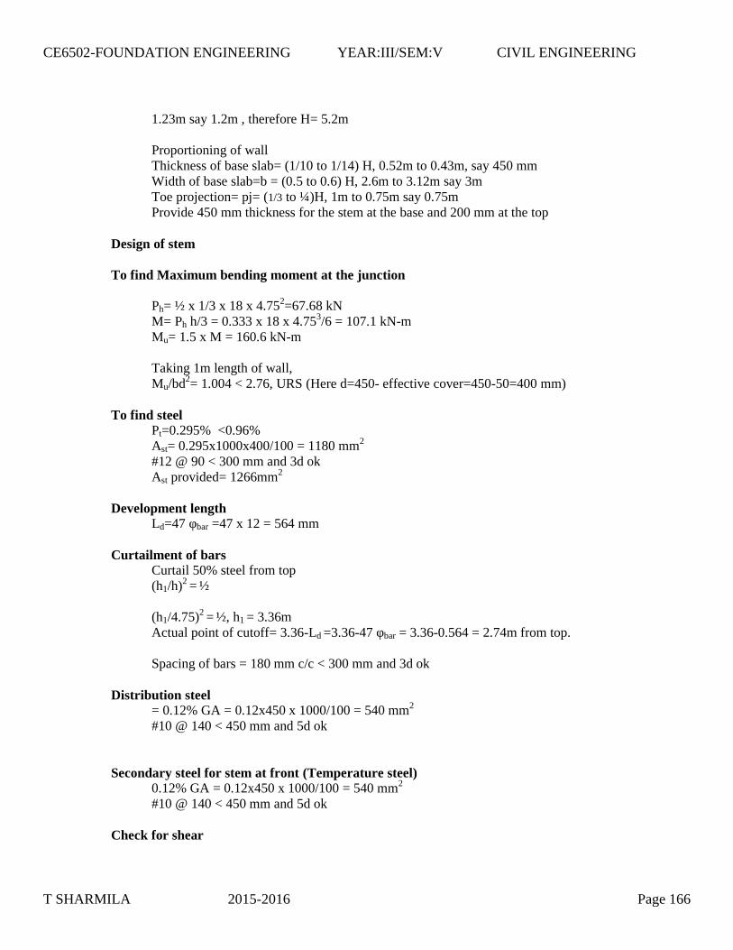
1.23m say 1.2m , therefore H= 5.2m
Proportioning of wallThickness of base slab= (1/10 to 1/14) H, 0.52m to 0.43m, say 450 mmWidth of base slab=b = (0.5 to 0.6) H, 2.6m to 3.12m say 3mToe projection= pj= (1/3 to ¼)H, 1m to 0.75m say 0.75mProvide 450 mm thickness for the stem at the base and 200 mm at the top
Design of stem
To find Maximum bending moment at the junction
Ph= ½ x 1/3 x 18 x 4.752=67.68 kNM= Ph h/3 = 0.333 x 18 x 4.753/6 = 107.1 kN-mMu= 1.5 x M = 160.6 kN-m
Taking 1m length of wall,Mu/bd2= 1.004 < 2.76, URS (Here d=450- effective cover=450-50=400 mm)
To find steelPt=0.295% <0.96%Ast= 0.295x1000x400/100 = 1180 mm2
#12 @ 90 < 300 mm and 3d okAst provided= 1266mm2
Development lengthLd=47 φbar =47 x 12 = 564 mm
Curtailment of barsCurtail 50% steel from top(h1/h)2 = ½
(h1/4.75)2 = ½, h1 = 3.36mActual point of cutoff= 3.36-Ld =3.36-47 φbar = 3.36-0.564 = 2.74m from top.
Spacing of bars = 180 mm c/c < 300 mm and 3d ok
Distribution steel= 0.12% GA = 0.12x450 x 1000/100 = 540 mm2
#10 @ 140 < 450 mm and 5d ok
Secondary steel for stem at front (Temperature steel)0.12% GA = 0.12x450 x 1000/100 = 540 mm2
#10 @ 140 < 450 mm and 5d ok
Check for shear
T SHARMILA 2015-2016 Page 166
CE6502-FOUNDATION ENGINEERING YEAR:III/SEM:V CIVIL ENGINEERING

Max. SF at Junction = Ph=67.68 kNUltimate SF= Vu=1.5 x 67.68 = 101.52 kNNominal shear stress =τv=Vu/bd = 101.52 x 1000 / 1000x400 = 0.25 MPaTo find τc : 100Ast/bd = 0.32%, From IS:456-2000, τc= 0.38 MPaτv< τc Hence safe in shear.
Stability analysis
Load Magnitude, kN Distance from A,m
Bending momentabout AkN-m
Stem W1 0.2x4.75x1x25 = 23.75 1.1 26.13
Stem W2 ½ x0.25x4.75x1x25 = 14.840.75 +
2/3x0.25=0.31613.60
Base slab W3 3.0x0.45x1x25 = 33.75 1.5 50.63Back fill, W4 1.8x4.75x1x18 = 153.9 2.1 323.20
total ΣW= 226.24 ΣMR=413.55Hori. earth
pressure =PH
PH =0.333x18x5.22/2=81.04 kN
H/3 =5.2/3 MO=140.05
120.6 kN/m2
30.16 kN/m2
24.1
97.9922.6
0.75m 0.45m 1.8m
Pressure below the Retaining Wall
T
x1
x2
W1
W2
W3
W4
b/2b/6e
xb
H/3
Pa
W
Hh
T SHARMILA 2015-2016 Page 167
CE6502-FOUNDATION ENGINEERING YEAR:III/SEM:V CIVIL ENGINEERING

Stability checks:
Check for overturning:FOS = ΣMR/ MO= 2.94 >1.55 safe
Check for Sliding:FOS = μ ΣW/ PH= 2.94 >1.55 safe
Check for subsidence:Let the resultant cut the base at x from toe T,x= ΣM/ ΣW= 1.20 m > b/3e= b/2 –x = 3/2 – 1.2 = 0.3m < b/6
Pressure below the base slab
Max. pressure=
b
e
b
W 61Pmax
120.66 kN/m2 < SBC, safe
Min. pressure =
b
e
b
W 61Pmin
30.16 kN/m2 > zero, No tension or separation, safe
Design of Heel
To fine the maximum bending moment
Load Magnitude, kNDistance from
C, mBM,
MC, kN-mBackfill 153.9 0.9 138.51
Heel slab 0.45x1.8x25 = 27.25 0.9 18.23Pressure distribution,
rectangle30.16 x 1.8 =54.29 0.9 -48.86
Pressure distribution,triangle
½ x 24.1 x1.8=21.69 1/3x1.8 -13.01
Total Load at junction 105.17Total BM at
junction ΣMC=94.86
Mu= 1.5 x 94.86 =142.3 kNmMu/bd2= 0.89 < 2.76, URSPt=0.264% < 0.96%Ast= 0.264x1000x400/100 = 1056 mm2
#16@ 190 < 300 mm and 3d okAst provided= 1058mm2
Development lengthLd=47 φbar =47 x 16 = 752mm
Distribution steel
T SHARMILA 2015-2016 Page 168
CE6502-FOUNDATION ENGINEERING YEAR:III/SEM:V CIVIL ENGINEERING
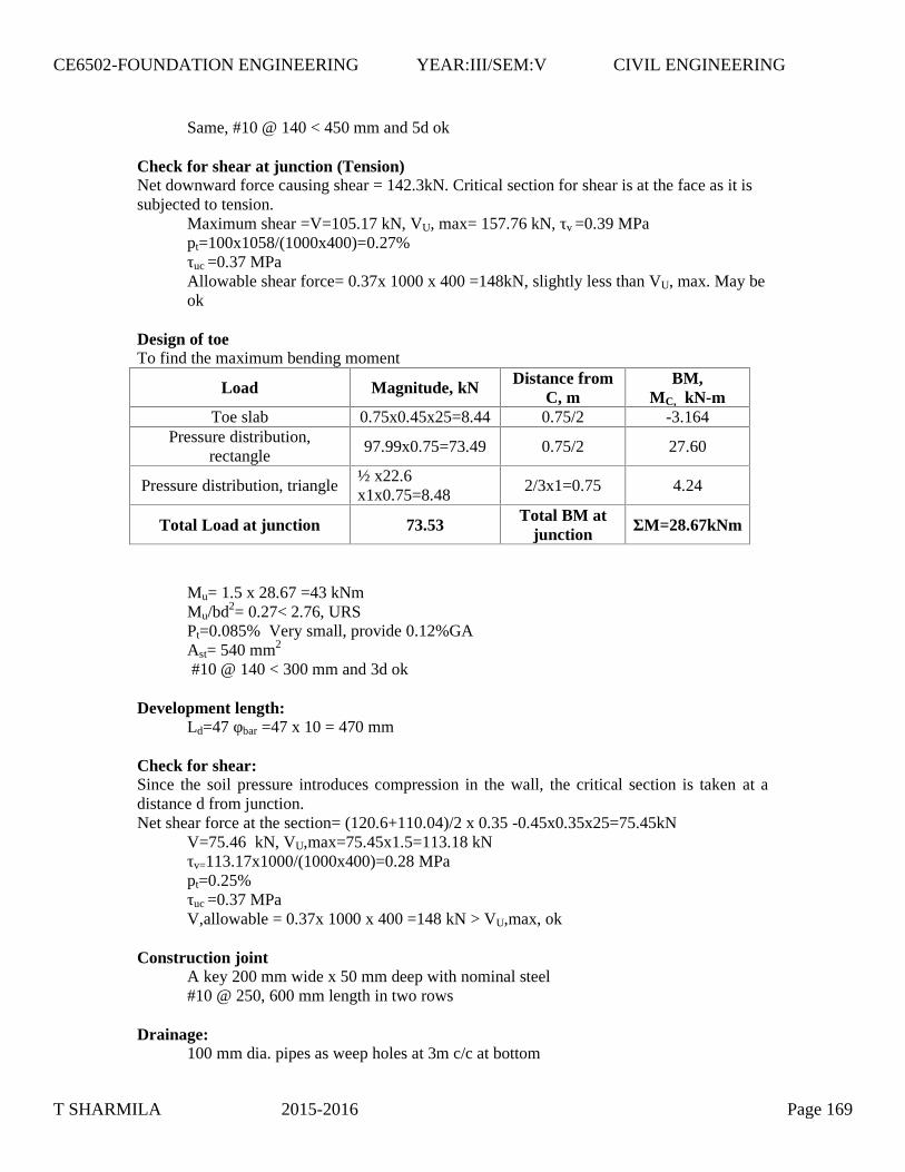
Same, #10 @ 140 < 450 mm and 5d ok
Check for shear at junction (Tension)Net downward force causing shear = 142.3kN. Critical section for shear is at the face as it issubjected to tension.
Maximum shear =V=105.17 kN, VU, max= 157.76 kN, τv =0.39 MPapt=100x1058/(1000x400)=0.27%τuc =0.37 MPaAllowable shear force= 0.37x 1000 x 400 =148kN, slightly less than VU, max. May beok
Design of toeTo find the maximum bending moment
Load Magnitude, kN Distance fromC, m
BM,MC, kN-m
Toe slab 0.75x0.45x25=8.44 0.75/2 -3.164Pressure distribution,
rectangle97.99x0.75=73.49 0.75/2 27.60
Pressure distribution, triangle½ x22.6x1x0.75=8.48
2/3x1=0.75 4.24
Total Load at junction 73.53Total BM at
junction ΣM=28.67kNm
Mu= 1.5 x 28.67 =43 kNmMu/bd2= 0.27< 2.76, URSPt=0.085% Very small, provide 0.12%GAAst= 540 mm2
#10 @ 140 < 300 mm and 3d ok
Development length:Ld=47 φbar =47 x 10 = 470 mm
Check for shear:Since the soil pressure introduces compression in the wall, the critical section is taken at adistance d from junction.Net shear force at the section= (120.6+110.04)/2 x 0.35 -0.45x0.35x25=75.45kN
V=75.46 kN, VU,max=75.45x1.5=113.18 kNτv=113.17x1000/(1000x400)=0.28 MPapt=0.25%τuc =0.37 MPaV,allowable = 0.37x 1000 x 400 =148 kN > VU,max, ok
Construction jointA key 200 mm wide x 50 mm deep with nominal steel#10 @ 250, 600 mm length in two rows
Drainage:100 mm dia. pipes as weep holes at 3m c/c at bottom
T SHARMILA 2015-2016 Page 169
CE6502-FOUNDATION ENGINEERING YEAR:III/SEM:V CIVIL ENGINEERING
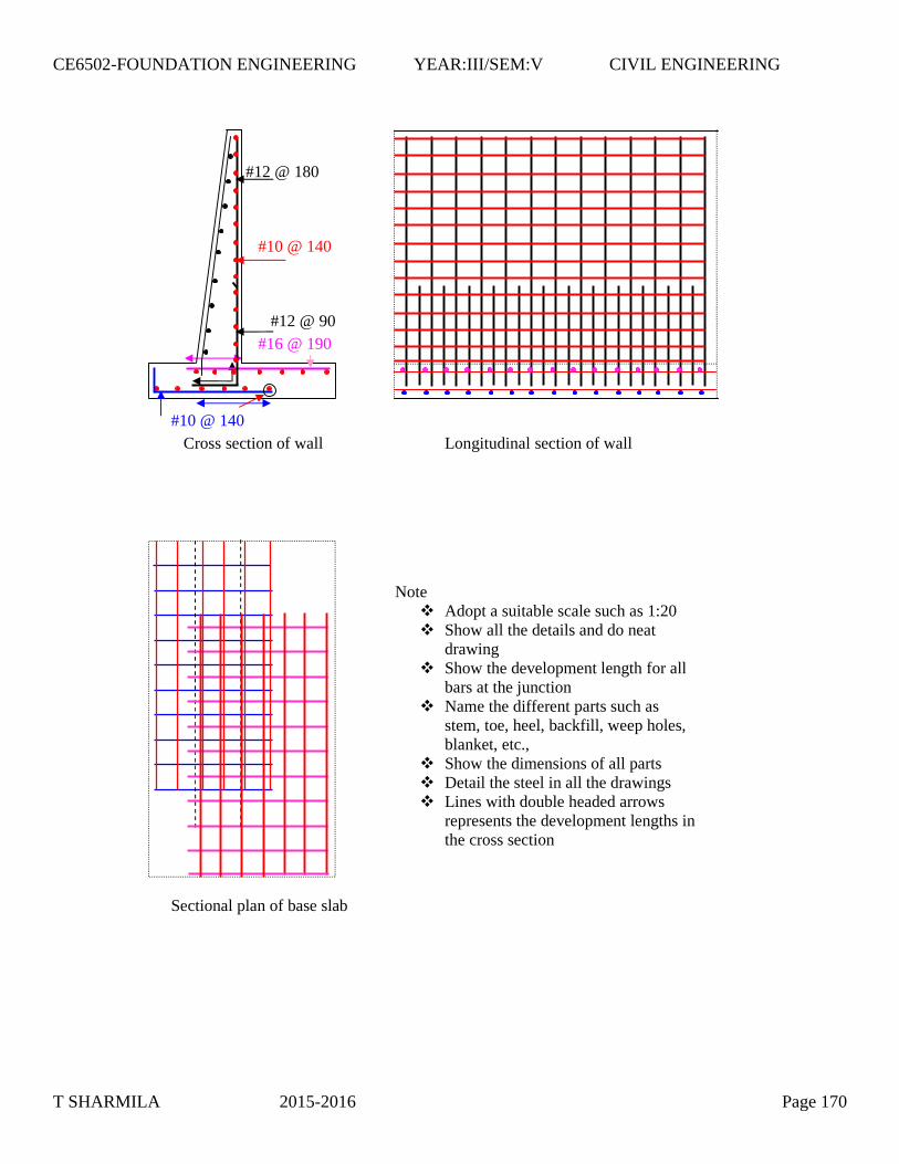
Cross section of wall Longitudinal section of wall
Sectional plan of base slab
Note Adopt a suitable scale such as 1:20 Show all the details and do neat
drawing Show the development length for all
bars at the junction Name the different parts such as
stem, toe, heel, backfill, weep holes,blanket, etc.,
Show the dimensions of all parts Detail the steel in all the drawings Lines with double headed arrows
represents the development lengths inthe cross section
#16 @ 190
#12 @ 180
#12 @ 90
#10 @ 140
#10 @ 140
T SHARMILA 2015-2016 Page 170
CE6502-FOUNDATION ENGINEERING YEAR:III/SEM:V CIVIL ENGINEERING