unit d - the bruce zonethebrucezone.weebly.com/uploads/9/8/6/6/9866336/unit_d_textbook_04_u8d... ·...
TRANSCRIPT
252
U N I T
D

In this unit, you will cover the following sections:
Machines are tools that help humans do work.
1.1 Simple Machines—Meeting Human Needs
1.2 The Complex Machine—A Mechanical Team
An understanding of mechanical advantage and workhelps in determining the efficiency of machines.
2.1 Machines Make Work Easier
2.2 The Science of Work
2.3 The Big Movers—Hydraulics
Science, society, and the environment are all importantin the development of mechanical devices and othertechnology.
3.1 Evaluating Mechanical Devices
3.2 Technology Develops through Change
253
1.0
2.0
3.0

Exploring
In July 2000, the first surgical robotic arm was approved for use inNorth America. Named “Da Vinci,” this device helps surgeonsperform operations inside people through very small incisions. Thistype of surgery is called “remote surgery” because the surgeon isnot directly touching the patient. In fact, with this new system, thesurgeon doesn’t even have to be in the same room with the patient.The surgeon can do the operation from another location. Thepatient’s local doctor needs only a connected computer, a videoterminal, and the Da Vinci arm.
254 Unit D: Mechanical Systems
The Da Vinci robotic arm allows surgeons to operate through small incisions. It also makesoperating at a distance possible.
255Exploring
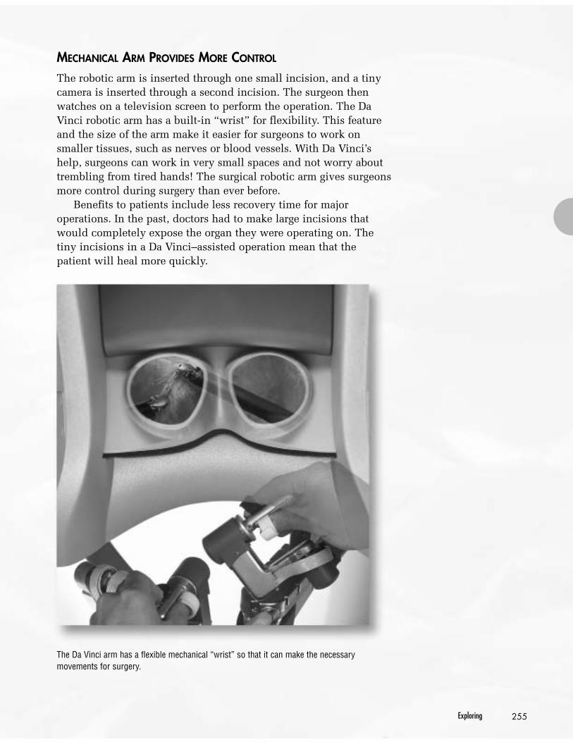
MECHANICAL ARM PROVIDES MORE CONTROL
The robotic arm is inserted through one small incision, and a tinycamera is inserted through a second incision. The surgeon thenwatches on a television screen to perform the operation. The DaVinci robotic arm has a built-in “wrist” for flexibility. This featureand the size of the arm make it easier for surgeons to work onsmaller tissues, such as nerves or blood vessels. With Da Vinci’shelp, surgeons can work in very small spaces and not worry abouttrembling from tired hands! The surgical robotic arm gives surgeonsmore control during surgery than ever before.
Benefits to patients include less recovery time for majoroperations. In the past, doctors had to make large incisions thatwould completely expose the organ they were operating on. Thetiny incisions in a Da Vinci–assisted operation mean that thepatient will heal more quickly.
The Da Vinci arm has a flexible mechanical “wrist” so that it can make the necessarymovements for surgery.

A SYSTEM OF COMPONENTS WORKING TOGETHER
Remotely controlled machines, such as the Da Vinci surgicalsystem, rely on several smaller components and technologies inorder to work. A computer controls the instruments as if thesurgeon was controlling the very tip of the scalpel in person. Themotions of the surgeon’s hands are transferred to hydraulic pumpsand electric motors that control the scalpel, drill, and scissors at theend of the robotic arm. The sensitivity of the tools is adjusted bycombinations of miniature gears, levers, and pulleys.
The development of a complex machine such as a robotic arm isthe result of teams of people working together. They use theirknowledge of mechanical systems and apply the latest technologyto solve problems.
256 Unit D: Mechanical Systems
E M E R G E N C Y !Now you have an opportunity to work as part of a teamin solving a problem. You and your group are part of theEmergency Robotic Environmental Response unit atRoboQuest Inc. An accident has just occurred. A roboticprobe exploring a mining drainage pit has becomewedged in a small passage. The probe is very heavy—about 100 kg. Your task is to retrieve the probe withoutdamaging it. You can see from the diagram of theaccident site that this will be a challenge.
Design a device that can help you extract the probe.Include the equipment listed below in your design:• a mechanical arm• steel beams about 2 m long• an assortment of gears• an assortment of pulleys with ropes
Before you start, read through Toolbox 3 to learn aboutproblem-solving techniques.
Give i t a TRY A C T I V I T Y
The accident site

257Exploring
FocusOn
SCIENCE AND TECHNOLOGY
As you work through this unit, you will learn how machines helpus do a variety of tasks. You will work with different mechanicalsystems to identify their components. You will also determine theirimpact on you and on the environment. Through this work, youwill be able to understand better how science and technology arerelated. Scientific knowledge leads to the development of newtechnologies. In turn, new technologies lead to scientificdiscoveries.
The activities in this unit focus on your developing solutions topractical problems. Often these problems have more than onepossible solution. You will learn to evaluate the options to find thebest solution. You will also develop your problem-solving skills asyou analyze working models of different types of machines todetermine their strengths and weaknesses. At the end of the unit,you will use your understanding of mechanical systems and yourskills in a final project. In this project, you will build a workingprototype of a mechanical gripper device.
As you work through this unit, use the following four questionsto guide your learning about mechanical systems:
1. How is energy transferred in mechanical devices?
2. How do mechanical devices provide for the controlledapplication of force?
3. How do mechanical devices work efficiently and effectively tomeet human needs?
4. What are the social and environmental impacts of mechanicaldevices?

Since farming began over 7000 years ago, humans have beencreating ever more sophisticated tools and machines. Machineshelp people use energy more effectively. In other words, amachine is a device that helps us do work.
The combine harvester shown here was developed to makeharvesting crops easier and quicker for farmers. Early combineswere pulled by horses or tractors. Later they were motorized, andtoday they are computerized and air-conditioned as well.Developments in technology for control systems, motors,materials, and other areas have all contributed to the design ofthese new combines.
In this section, you will learn about simple machines andhow they help people perform tasks. You will learn that simplemachines can work together in a system to form a complexmachine. You will also discover how linkages and transmissionstransfer energy in machines.
Machines are tools that helphumans do work.
Key ConceptsIn this section, you will learnabout the following keyconcepts:• systems and subsystems• transmission of force and
motion• simple machines
Learning OutcomesWhen you have completed thissection, you will be able to:• describe examples of
mechanical devices used inthe past to meet particularneeds
• describe an example of how acommon need has been metin different ways over time
• analyze a mechanical deviceby describing how differentparts contribute to its overallfunction and identifying theparts that are simplemachines
• identify the sources of energyfor some familiar mechanicaldevices
• identify linkages andtransmissions in amechanical device anddescribe their generalfunctions
1.0
258 For Web links relating to 1.0, visit www.pearsoned.ca/scienceinaction

259Machines Are Tools That Help Humans Do Work
1.1 Simple Machines—Meeting Human Needs
The earliest machines were very simple devices. For example,people used levers to pry rocks out of the ground. Then they used aramp to help them raise the rocks as they built walls and otherlarge structures. Each machine was designed to meet specific needs,such as lifting rocks or splitting wood. Although each machine wasdifferent, they all had one thing in common. These first machinesdepended on people or animals for their source of energy.
Working with a partner, try to determine what tasks the historicmachines in Figure 1.1 were used for and how they worked. Lookfor clues in the pictures, or research the names of the machines tofind out what needs these machines were designed to meet. Also,try to determine the approximate time periods when thesemachines were used.
Roman AqueductsThousands of years ago, Roman engineers developed a mechanical systemfor transporting water for many kilometres to supply major cities. Thesestructures, known as aqueducts, were made up of three main parts: 1. pumps to raise the water into reservoirs and control the rate of water flow2. sloped channels to carry the water to the cities3. distribution systems in the cities to carry the water to central bathhouses
and local reservoirsThe aqueducts were so well designed and constructed that many of them canstill be seen today in Europe, more than 2000 years after they were built!
i n f oBIT
Figure 1.1a) Mill wheel Figure 1.1b) Nutcracker Figure 1.1c) Plow

260 Unit D: Mechanical Systems
MEETING THE SAME NEED IN DIFFERENT WAYS
One of the most basic human needs is fresh water. You haverunning water in your home because of a combination ofmechanical systems. These systems move water from its source,through a series of pipes, to your tap. Pumps powered by electricitykeep the water moving.
Before pumps were available, people used gravity to movewater. Water was stored in large, raised tanks. Gravity caused it tomove down from the pipes through tanks to where it was needed inthe community.
In the past, one of the most common ways of raising water intothese tanks was a type of water wheel called a sakia (also called aPersian wheel). A sakia has a series of buckets attached to a longrope, which is draped over a large wheel. Animals such as donkeys,camels, or cows turned the wheel, which raised the buckets of water.
ARCHIMEDES INVENTS A MORE EFFICIENT WAY
Although the sakia worked well in lifting water, people werealways looking for more efficient ways to do this task. One of thesemethods was invented by the famous Greek scientist andmathematician Archimedes. His device used a large screw inside atube. One end of the tube is placed in water. When the screw turns,it raises water up to the top of the tube. Called an Archimedesscrew, this device can move large volumes of water or othersubstances. Originally it was powered by hand. Today it is poweredby gasoline or electric motors.
Figure 1.2 A sakia can beused to haul water out of awell for storage in largetanks or for irrigation.

261Machines Are Tools That Help Humans Do Work
Hundreds of years later, the famous Italianscientist Leonardo da Vinci designed a water liftusing two Archimedes screws to raise water up to astorage tank in a water tower. His original plans areshown in Figure 1.3. The Archimedes screw is stillin use today. Figure 1.4 shows a modern exampleof an Archimedes screw being used to move graininto a truck.
SIMPLE MACHINES
The earliest machines, known as simple machines, are still usedtoday. A simple machine is a tool or device made up of one basicmachine. In their work, engineers must be aware of the strengthsand limitations of each type of simple machine. This knowledgeenables them to design combinations of these machines to docomplicated tasks.
Before you read about the advantages and disadvantages of eachsimple machine, make a chart in your notebook similar to the onebelow. Fill in your chart as you read about the different machines.
Simple Machine Advantages Disadvantages
lever
There are six simple machines that help us do work: the lever,inclined plane, wedge, screw, pulley, and wheel and axle. Each oneis used for specific tasks. Each has its own advantages anddisadvantages.
Figure 1.3 Leonardo da Vinci’s design for usingtwo Archimedes screws to raise water up into awater tower.
Figure 1.4 The spiral motion of the slowly turningscrew moves the grain into the truck.
B
effort force
lever
fulcrumA
262 Unit D: Mechanical Systems
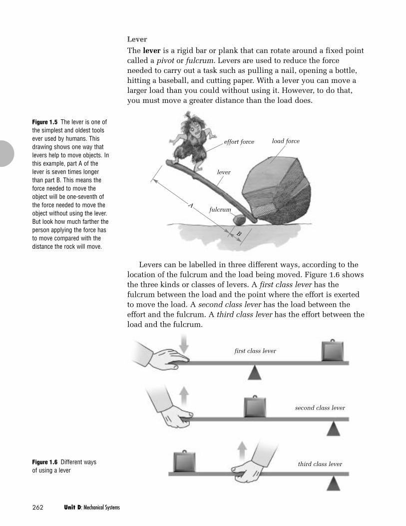
Figure 1.5 The lever is one ofthe simplest and oldest toolsever used by humans. Thisdrawing shows one way thatlevers help to move objects. Inthis example, part A of thelever is seven times longerthan part B. This means theforce needed to move theobject will be one-seventh ofthe force needed to move theobject without using the lever.But look how much farther theperson applying the force hasto move compared with thedistance the rock will move.
Figure 1.6 Different waysof using a lever
load force
LeverThe lever is a rigid bar or plank that can rotate around a fixed pointcalled a pivot or fulcrum. Levers are used to reduce the forceneeded to carry out a task such as pulling a nail, opening a bottle,hitting a baseball, and cutting paper. With a lever you can move alarger load than you could without using it. However, to do that,you must move a greater distance than the load does.
Levers can be labelled in three different ways, according to thelocation of the fulcrum and the load being moved. Figure 1.6 showsthe three kinds or classes of levers. A first class lever has thefulcrum between the load and the point where the effort is exertedto move the load. A second class lever has the load between theeffort and the fulcrum. A third class lever has the effort between theload and the fulcrum.
first class lever
second class lever
third class lever

263Machines Are Tools That Help Humans Do Work
Inclined planeImagine that you had to lift a very heavy box from the floor onto atable. You would have to exert a large force to lift it straight upfrom the floor onto your desk. An inclined plane or ramp wouldmake it easier for you to move the box up onto the desk. Aninclined plane makes it possible to lift heavy objects using asmaller force. However, you have to exert the force over a largerdistance, compared with lifting the object straight up. As well, aramp is generally useful only for small inclines. The steeper theangle of a ramp, the harder it is to control the motion of an objectas it moves up or down the ramp. Examples of inclined planesinclude loading ramps on buildings and wheelchair access ramps.
WedgeA wedge is similar in shape to an inclined plane, but it is used in adifferent way. The wedge machine is forced into an object. Bypressing on the wide end of the wedge, you can exert a force on thenarrow end so it splits an object apart. The wedge increases theforce that you apply on the object. But it moves a greater distanceinto the object than the split it causes. Unlike the ramp, a wedgecan be used only in one direction: to push objects apart. Knives andaxes are examples of wedges.
Figure 1.7 An inclined plane or ramp canhelp move large, heavy objects that are tooheavy to lift straight up.
Figure 1.8 A knife blade isa very thin wedge.

264 Unit D: Mechanical Systems
ScrewA screw is a cylinder with a groove cut in a spiral on the outside.Using a screw helps you increase the force you use. It can penetratematerials using a relatively small force. A screw can also be usedfor converting rotational (turning) motion to linear motion (motionin a straight line). You saw an example of this earlier in the picturesof the Archimedes screw. Figure 1.9 shows how the screw moves ina spiralling motion. This is the rotational motion. However, thescrew is also moving the water along a line from point A to point B.Most screws will move objects very slowly.
PulleyA pulley consists of wire, rope, or cable moving on a groovedwheel. Pulleys may be made up of one or many wheels and can befixed in place or movable. They can be linked together in systemsfor moving and lifting objects. Pulleys help you lift larger loadsthan you could lift on your own.
Figure 1.9 An Archimedesscrew helps to lift water orother materials.
r eSEARCH
Early ToolsMany of the toolsused by Canada’searliest inhabitantswere simplemachines. Usingresources available inyour library or on theInternet, identify atool that was used byAboriginal peoples inCanada before theyear 1800. Once youhave identified a tool,determine what needsthe tool met, and thesimple machine(s) itcontained.
Figure 1.10 Two types of pulleys
B
A
rotationalmotion ofscrew
linear motion of waterfrom A to B

265Machines Are Tools That Help Humans Do Work
Wheel and AxleThe wheel and axle is a combination of two wheels of differentdiameters that turn together. A longer motion on the wheelproduces a shorter but more powerful motion at the axle. Thesteering wheel and steering column in a car together form a wheeland axle. That combination is one example of using a wheel andaxle to increase the size of a force. The drawback is that you haveto turn a greater distance (a larger wheel) to apply the force. Awheel and axle can also be used to increase speed. Wheels onbicycles are examples of using this simple machine to increasespeed. The rider exerts a large force to turn the axle, which causesthe bicycle’s wheel to turn. The rider moves faster on the bicyclethan without it.
Figure 1.12 A doorknob isa wheel-and-axle machine.Which part is the wheel andwhich part is the axle?
Figure 1.11 Pulleys make it possible tolift large, heavy loads.
wheel axle

266 Unit D: Mechanical Systems
Inquiry Act iv i ty
Figure 1.13 Step 4. Pull themass steadily up the ramp.
TH E R I G H T MA C H I N E F O R T H E JO B
Before You Start ...Have you ever tried to lift a very heavy object? Did you need to have anotherperson help you, or maybe you used a lever or a ramp to help you? Thesedevices are both simple machines. In this activity, you will investigate a variety ofsimple machines and determine which machine is best suited for lifting a mass.
The QuestionWhich simple machine requires the least amount of force to lift a 1-kg mass?
Procedure
Station 1. Lifting without a Machine1 Tie a loop at one end of the 30-cm string, so the loop fits over the hook on
the spring scale. Tie the other end of the string to the 1-kg mass.2 Lift the spring scale just until the mass is hanging from the scale. Now slowly
raise the load 10 cm. Measure and record the force needed to lift the mass.
Station 2. Lifting with a Ramp3 Set up the ramp so that the highest point of the ramp is 10 cm above the top
of the surface it’s sitting on.4 Place the mass on the bottom of a ramp and attach the loop of string to the
spring scale again. With your hand at the top of the ramp, pull the masssteadily up the ramp. Measure and record the force needed to raise the mass.
Station 3. Lifting with a Pulley System5 Tie one end of the 60-cm string to the mass. Place the mass on a table below
the pulleys and thread the string between the pulleys.6 Tie a loop at the loose end of the string and attach the string to the spring
scale. Use the pulleys to raise the load 10 cm. Measure and record the forceneeded to lift the mass.
Figure 1.14 Step 6. Use thepulleys to lift the mass up 10 cm.
Materials & Equipment• 30-cm string• 1-kg mass• 20-N spring scale• ramp• 60-cm string• pulley system• metre-stick• 10-cm string• pivot or fulcrum

267Machines Are Tools That Help Humans Do Work
Figure 1.15 Step 7. Themetre-stick is now actingas a lever.
Station 4. Lifting with a Lever7 Place the metre-stick on the fulcrum so that the fulcrum is in the middle of
the metre-stick. Hang the mass from one end of the lever. Use the 10-cmpiece of string to make a loop and attach the spring scale to the opposite endof the lever. This end of the lever should be far enough above the table or thefloor so you can use the spring scale to pull down on it.
8 Pull down the spring scale so the lever raises the mass at the other end.Record the force need to lift the mass.
9 Change the location of the fulcrum under the metre-stick and repeat step 8.
Collecting Data10 Record the force needed to lift the mass in each case.11 Record your observations of the differences when you changed the position
of the fulcrum under the metre-stick.
Analyzing and Interpreting12 What was the most difficult method of raising the mass? What was the
easiest method? Why do you think that is?13 For the lever (the metre-stick):
a) What effect does the location of the fulcrum have on the force you mustuse to lift the mass?
b) What effect does the location of the fulcrum have on the distance thatyour hand moved and the mass moved?
14 What feature of the lever made it easier to lift the load?15 What change would you make to the ramp to make it even easier to raise the
mass to a 10-cm height?
Forming Conclusions 16 Using sentences and diagrams, describe how a simple machine increases the
force that you apply to an object. Include the features of the simple machinesin this activity as examples.

CHECK AND REFLECT
1. Identify which simple machines you would use in each of thefollowing situations: a) digging a deep hole b) moving a heavy rock from one side of your yard to the other
2. a) Give examples of energy sources used for modern machines,such as cars and sewing machines.
b) Are the energy sources in question 2a) the same as thoseused in machines before the 1900s? Explain your answer.
3. When a simple machine increases the force you exert, whatother factor changes?
4. One of the most important tools for pioneers in Canada was theaxe. What two simple machines make up the axe?
268 Unit D: Mechanical Systems
THE EFFECTS OF SIMPLE MACHINES
Simple machines can be used to obtain one of the effects shownbelow. Remember that a simple machine can increase the force thatyou apply, or change the direction of the force, but there is a cost.The force that you apply has to move farther than the load does.
Figure 1.20 Question 4
Figure 1.16 To raise the flag,you pull down. The pulleychanges your downward pullto an upward pull on the flag.
Figure 1.17 A small force onthe handle of the screwdriverbecomes a large force in theshaft. This large force canthen be used to undo screwsthat would be impossible toremove with your fingersalone.
Figure 1.18 To cut, you movethe scissors’ handlestogether. The scissors’ bladescut the paper more quicklythan you move the handlestogether. And they cut fartherthan the distance the handlesmove. Try it and see!
Figure 1.19 A lever like thisstaple remover transfers forceto the object being moved. Inthis case, it is transferring theforce from the student to thestaple.
1 Changing the directionof a force (for example,a pulley on a flagpole)
2 Multiplying force (forexample, a screwdriver)
3 Increasing or decreasingspeed (for example,scissors)
4 Transferring force (forexample, a stapleremover)

269Machines Are Tools That Help Humans Do Work
1.2 The Complex Machine— A Mechanical Team
As time passed, people began living in larger communities. Theyneeded to find ways to build larger buildings, provide runningwater, and develop transportation systems for moving people andgoods. To do these and other tasks, they developed ever morecomplicated machines. They also found new ways to power thesemachines.
Within the last two centuries, scientists, engineers, and otherinventors have developed machines that use sources of energy suchas coal, oil, and electricity. These large supplies of energy,combined with new materials and new technologies, caused anindustrial revolution. Large factories were now possible.
The first factories used powerful new machines to mass-produce goods. The newly invented steam engine transported thesegoods across countries in record time. People now had access tomore food, clothing, tools, and raw materials than they ever hadbefore, and their standard of living improved.
The development of new technologies has continued at atremendous rate. Today we are almost completely dependent onmachines. Think of the things that you enjoy doing that depend ona machine for delivering energy or for moving objects. Can youimagine how your life would change if you could not usemachines?
Figure 1.21 The inventionof the steam engine led tothe development of trains.Trains could travel fasterthan horses and haul muchlarger loads.
The Changing BicycleThe bicycle is one ofthe most efficientmachines everinvented to translatehuman energy intomotion. The penny-farthing shown herewas an early bicycledesign. It had onlylevers for steering,and the wheel andaxle for moving.
i n f oBIT

COMPLEX MACHINES
Most of the devices that we use today are made up of severalsimple machines. These devices are called complex machines. Acomplex machine is a system in which simple machines all worktogether. A system is a group of parts that work together to performa function. For example, the bicycle in Figure 1.22 is a system formoving a person.
Within the bicycle are groups of parts that perform specificfunctions, such as braking or steering. These groups of parts arecalled subsystems. The subsystems in a complex machine have justone function each. A subsystem usually contains a simple machine.All the subsystems work together to complete the task that thecomplex machine was designed to do.
The bicycle is a good example of a complex machine. Severalsubsystems work together to move you forward at different speeds,allow you to turn, and help you stop. Each subsystem uses a simplemachine to help you do the task more easily. Figure 1.22 shows themajor subsystems in a typical bicycle.
270 Unit D: Mechanical Systems
Figure 1.22 A bicycle is a complex machine made up of simple machines that work together.The whole bicycle is a system, made up of many subsystems.
wheel and axle
chain transfers the forcefrom the pedals to the gears
pedals act as a lever, increasing the forceyou apply to the wheel and axle
brakes use a lever to increase theforce you apply with your hands
gears reduce the forcethat you need to apply

271Machines Are Tools That Help Humans Do Work
A N A L Y Z I N G A M E C H A N I C A L D E V I C E
You are surrounded by a wide variety of machines, both big and small, in yourdaily life. Now you have an opportunity to look inside one of those machines andsee how it works. You can use the one illustrated here or a device provided byyour teacher.
Give i t a TRY A C T I V I T Y
Figure 1.23 What is the function of this device?
Figure 1.24 How does each subsystemcontribute to the device’s function?
Work with your partner to answer the following questions.• What is the overall function of the device?• How many individual subsystems can you identify in the device?
Describe how each one contributes to the device’s function.• Do any of these subsystems contain a simple machine? If so,
describe them.
Use a flowchart or diagrams to show how all the subsystems work togetherto make the device function.

axle
gearschain
drive wheel
SUBSYSTEMS THAT TRANSFER FORCES
Some of the subsystems in complex machines that produce motionplay a role in the transfer of energy or force. In mechanical devices,these subsystems are called linkages and transmissions. Gears areoften an important part of these subsystems.
LinkagesA complex machine moves an object by transferring energy from anenergy source to the object. For a bicycle, you are the energysource. The bicycle’s wheels are the objects that you must turn tomake the bicycle move. The linkage is the part that transfers yourenergy from the pedals to the back wheel. In a bicycle, the chain isthat linkage.
Many machines use high-tension belts instead of chains torotate objects. You may have seen a belt used as a linkage in oldercar engines. This is the fan belt, which transfers energy from theengine to spin the cooling fan. The fan moves air through theradiator to keep the engine from overheating.
Chains or belts form a direct link between two separatedwheels, so that when one turns, the other will turn in the samedirection. If one wheel is larger, it will rotate more slowly, but witha larger force, than the smaller wheel. Chains have less chance ofslipping than a belt, but belts are more flexible.
272 Unit D: Mechanical Systems
Figure 1.25 In a bicycle,the chain is the linkage thatdrives the gearwheels.When you shift gears, youmove the chain from thelarger gearwheel to thesmaller ones or vice versa.
pedal
gears

273Machines Are Tools That Help Humans Do Work
Figure 1.26 The gears on an eggbeater changethe vertical motion of your cranking to thehorizontal motion of the beaters.
TransmissionsMost machines that move objects are more complex than a bicycle.They usually move much larger loads than just one person. Thesemachines use a special type of linkage called a transmission totransfer the energy from the engine to the wheels. A transmissioncontains a number of different gears. This allows the operator toapply a large force to move objects slowly, or a smaller force tomove objects quickly.
Transmissions are similar to the gears on a bicycle, except thatthey are designed to transfer much larger forces. In a car, forexample, the driver can select a low gear to start the car moving,and then change to higher gears when driving on a highway.
In a low gear, the transmission connects a small wheel to alarger wheel, so the wheels rotate more slowly than the enginedoes. This increases the amount of power but reduces the car’sspeed. In a high gear, the transmission connects a large wheel to asmaller wheel, so the wheels rotate faster than the engine. Thisreduces the amount of power but increases the car’s speed.
GEARS
Gears are essential components ofmost mechanical systems. Theyconsist of a pair of wheels thathave teeth that interlink. Whenthey rotate together, one gearwheeltransfers turning motion and forceto the other. The larger gearwheelrotates more slowly than thesmaller gearwheel, but it rotateswith a greater force. Gears can beused to increase or decrease speedin a machine. Both cars andbicycles use gears to change speed.Gears can also be used to changethe direction of motion of amechanical device like theeggbeater in Figure 1.26.
r eSEARCH
Automatic and ManualTransmissionsWhat is the differencebetween an automatictransmission and amanual transmission ina car or truck? Whichone is better? Whichone costs more? Why?

274 Unit D: Mechanical Systems
Inquiry Act iv i ty
BI C Y C L E GE A R S
The QuestionWhat are the differences among three different gears on a bicycle?
Procedure1 With your group, observe the two sets of gears on the bicycle—front and
rear. The rear set has more gears than the front one does. The gears aremade up of flat, toothed disks called sprockets.
2 As a group, decide which three gears you will study. Count the number ofteeth on the front and rear sprockets for each gear. Record this information inyour table.
3 Measure the distance from the centre of the rear wheel to the edge of the tire.This is the radius of the rear wheel.
4 Measure the distance from the centre of the front sprocket to the outer-mostpoint of the pedal. This is the radius of the circle that the pedal makes when itmoves.
5 Attach a spring scale to the pedal. Apply just enough constant force to turnthe pedal for one complete revolution. How much force is required to turn thepedal one turn? Record your result.
6 How many times did the back wheel turn for one turn of the pedal? Recordyour result.
7 Repeat steps 5 and 6 for the other two gears. Record your results.
Collecting Data8 Record your observations in your notebook in a table like the one below.
Analyzing and Interpreting9 For each gear, divide the number of teeth on the front sprocket by the number
of teeth on the rear sprocket. Record your results in your notebook.10 Find the circumference of the circle the pedal makes when it goes through
one turn. To do this, multiply the radius of the pedal’s circle by 2� or 6.28.This is the linear distance the pedal travels in one turn. Record your result inyour notebook.
11 Find the circumference of the rear wheel by multiplying the wheel’s radius by2� or 6.28. This is the linear distance the wheel travels in one turn. Recordyour result in your notebook.
12 For each gear, determine how far the rear wheel travelled with one completeturn of the pedal. This can be calculated by multiplying the circumference of
Figure 1.27 The gears on abicycle are divided betweenthe front and the rear.
Gear
Lowest gearMiddle gearHighest gear
Front sprocket: No. of teeth
Rear sprocket: No. of teeth
Radius of rear wheel
Radius of pedal
Force needed for 1 pedal
turn
No. of back wheel turns
rear sprockets
front sprocketspedal
Materials & Equipment• multi-geared bicycle• spring scale• metre-stick or measuring
tape
Caution!Turn the pedal slowly andkeep your fingers awayfrom the wheel spokesand gears.

275Machines Are Tools That Help Humans Do Work
How Gears WorkAlmost any device that contains spinning parts uses gears. If youlook inside a VCR, you’ll see gears. You may have an electric meterwith a clear plastic cover on the outside of your house. Take a lookin it and you will see many different sizes of gears.
Gears are important in mechanical systems because they controlthe transfer of energy in the system. For example, in a bicycle, theycontrol the transfer of energy from the rider to the wheels. Theyallow the rider to control and change the speed at which the wheelsturn. In a car or other motorized vehicle, they control the transfer ofenergy from the engine to the wheels.
Gear wheels work together in gear trains of two or more wheels,like the one shown in Figure 1.28. The gear that has a force appliedto it from outside the gear train is the driving gear. It then applies aforce to the other gear, called the driven gear.
How Gears Affect SpeedIf the driving gear is larger than the driven gear, the turning speedin the system increases. When you rotate the large gear once, itrotates the smaller gear several times. Think about the gears in aneggbeater like the one shown in Figure 1.26. When you turn thecrank, you rotate the large gear, which is the driving gear. It rotatesthe smaller gears attached to the beaters through four completeturns. This makes the beaters move much faster than the handle, soyou can beat the eggs more quickly.
Gears like these that increase the speed of rotation in a deviceare called multiplying gears. Reducing gears decrease the turningspeed in a device. In reducing gears, the driving gear is smaller andhas fewer teeth than the driven gear, as shown in Figure 1.29.
In a bicycle, gear wheels do not mesh directly with each other.They are joined by the chain, which provides the linkage betweenthe different sizes of gear wheels. When you shift gears, you movethe chain from one gear wheel to another. In this way, you canchange how fast you go when you pedal.
Figure 1.29 Reducing gearsdecrease turning speed in adevice.
Figure 1.28 A gear train