unit-5 permanent magnet synchronous motor introductioneeedrmcet.zohosites.com/files/iii year/sem...
TRANSCRIPT
UNIT-5
PERMANENT MAGNET SYNCHRONOUS MOTOR
INTRODUCTION
A permanent magnet synchronous motor is also called as brushless permanent magnet sine wave motor. A sine wave motor has a
1. Sinusoidal or quasi-sinusoidal distribution of magnetic flux in the air gap. 2. Sinusoidal or quasi-sinusoidal current wave forms. 3. Quasi-sinusoidal distribution of stator conductors (i.e.) short-pitched and distributed or
concentric stator windings.
The quasi sinusoidal distribution of magnetic flux around the air gap is achieved by tapering the magnet thickness at the pole edges and by using a shorter magnet pole arc typically 120º.
The quasi sinusoidal current wave forms are achieved through the use of PWM inverters and this may be current regulated to produce the best possible approximation to a pure sine wave. The use of short pitched distributed or concentric winding is exactly the same as in ac motors.
CONSTRUCTION AND PRINCIPLE OF OPERATION
Permanent magnet synchronous machines generally have same operating and performance characteristics as synchronous machines. A permanent magnet machine can have a configuration almost identical to that of the conventional synchronous machines with absence of slip rings and a field winding.
Construction
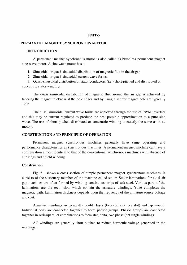
Fig. 5.1 shows a cross section of simple permanent magnet synchronous machines. It consists of the stationary member of the machine called stator. Stator laminations for axial air gap machines are often formed by winding continuous strips of soft steel. Various parts of the laminations are the teeth slots which contain the armature windings. Yoke completes the magnetic path. Lamination thickness depends upon the frequency of the armature source voltage and cost.
Armature windings are generally double layer (two coil side per slot) and lap wound. Individual coils are connected together to form phasor groups. Phasor groups are connected together in series/parallel combinations to form star, delta, two phase (or) single windings.
AC windings are generally short pitched to reduce harmonic voltage generated in the windings.
Coils, phase groups and phases must be insulated from each other in the end-turn regions and the required dielectric strength of the insulation will depend upon the voltage ratings of the machines.
Fig. 5.1 structure of the stator and rotor
In a permanent magnet machines the air gap serves an role in that its length largely determines the operating point of the permanent magnet in the no-load operating condition of the machines .Also longer air gaps reduce machines windage losses.
The permanent magnets form the poles equivalent to the wound field pole of conventional synchronous machines. Permanent magnet poles are inherently ―salientǁ and there is no equivalent to the cylindrical rotor pole configurations used in many convectional synchronous machines.
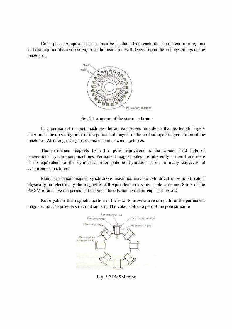
Many permanent magnet synchronous machines may be cylindrical or ―smooth rotorǁ physically but electrically the magnet is still equivalent to a salient pole structure. Some of the PMSM rotors have the permanent magnets directly facing the air gap as in fig. 5.2.
Rotor yoke is the magnetic portion of the rotor to provide a return path for the permanent magnets and also provide structural support. The yoke is often a part of the pole structure
Fig. 5.2 PMSM rotor

Damper winding is the typical cage arrangement of conducting bars, similar to induction motor rotor bars and to damper bars used on many other types of synchronous machines. It is not essential for all permanent magnet synchronous machines applications, but is found in most machines used in power applications.
The main purpose is to dampen the oscillations about synchronous speed, but the bars are also used to start synchronous motors in many applications.
The design and assembly of damper bars in permanent magnet machines are similar to the other types of synchronous machines.
Synchronous machines are classified according to their rotor configuration. There are four general types of rotors in permanent magnet synchronous machines. They are
4. Peripheral rotor 5. Interior rotor 6. Claw pole or lundell rotor. 7. Transverse rotor.
� Peripheral rotor
The permanent magnets are located on the rotor periphery and permanent magnet flux is radial.
� Interior rotor
The permanent magnets are located on the interior of the rotor and flux is generally radial. � Claw pole or Lund ell
The permanent magnets are generally disc shaped and magnetized axially. Long soft iron extensions emanate axially from periphery of the discs like claws or Lund ell poles. There is set of equally spaced claws on each disc which alternate with each other forming alternate north and south poles.
� Transverse rotor
In this type the permanent magnets are generally between soft iron poles and the permanent magnet flux is circumferential. In this soft iron poles at as damper bars. Magnetically this configuration is similar to a reluctance machine rotor, since the permeability of the permanent magnet is very low, almost the same as that of a non-magnetic material. Therefore, reluctance torque as well as torque resulting from the permanent magnet flux is developed.
Thus BLPM sine waves (SNW) motor is construction wise the same as that of BLPM square wave (SQW) motor. The armature winding and the shape of the permanent magnet are so designed that flux density distribution of the air gap is sinusoidal(i.e.) .The magnetic field setup by the permanent magnet in the air gap is sinusoidal
EMF EQUATION OF BLPM SINE WAVE MOTOR
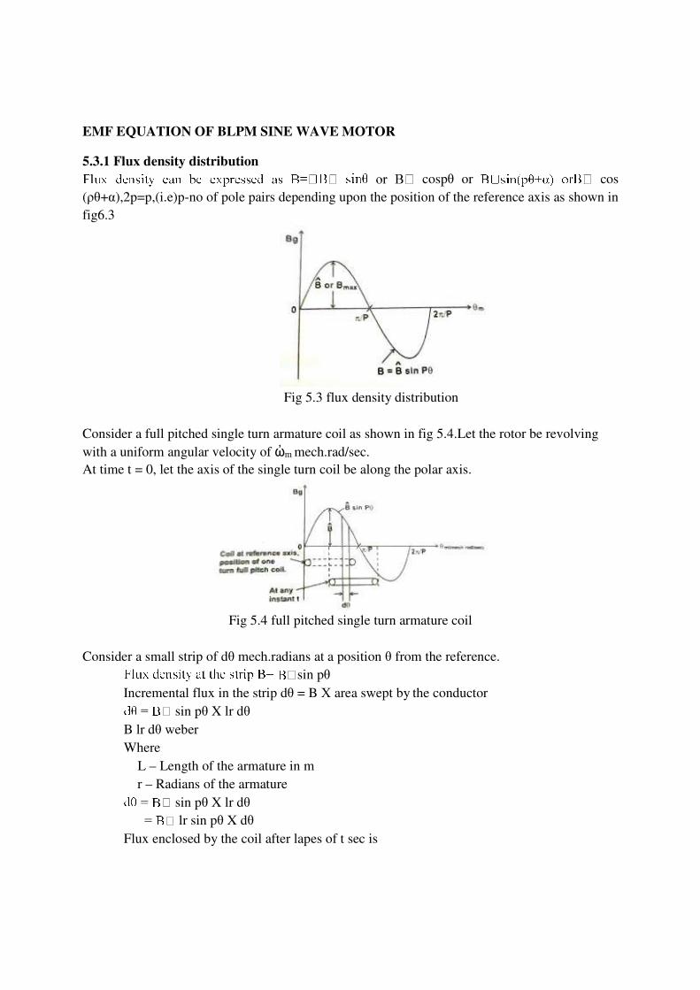
5.3.1 Flux density distribution
cospθ or cos (ρθ+α),2p=p,(i.e)p-no of pole pairs depending upon the position of the reference axis as shown in fig6.3
Fig 5.3 flux density distribution
Consider a full pitched single turn armature coil as shown in fig 5.4.Let the rotor be revolving with a uniform angular velocity of ὠm mech.rad/sec. At time t = 0, let the axis of the single turn coil be along the polar axis.
Fig 5.4 full pitched single turn armature coil
Consider a small strip of dθ mech.radians at a position θ from the reference. sin pθ
Incremental flux in the strip dθ = B Χ area swept by the conductor sin pθ X lr dθ
B lr dθ weber Where
L – Length of the armature in m r – Radians of the armature sin pθ X lr dθ
lr sin pθ X dθ Flux enclosed by the coil after lapes of t sec is
ɸ = ……..(5.1)
ɸ lr/p) cos pθ ωmt
5.3.2. EMF Equation of an ideal BLPM sine wave motor
As per faradays law of electromagnetic induction, emf induction in the single turn coil.
e = -N d ɸ /dt
-dɸ /dt as N=1 = - dɸ lr/p) cos pθ ωmt)
lr/p) p ωm sin p ωmt
lr ωm sin p ωmt ……..(5.2)
let the armature winding be such that all turns of the phase are concentrated full pitched and located with respect to pole axis in the same manner.
Let Tph be the number of turns connected in series per phase. Then the algebraic addition of the emfs of the individual turns gives the emf induced per phase as all the emf are equal and in phase.
eph lr ωm sin p ωmt)Tph ……..(5.3) lr ωm Tph sin p ωmt
= Ĕ ph sin p ωmt where p ωmt = ωe angular frequency in red/sec
= Ĕ ph sin ωet
Ĕ ph lr ωm Tph ωm ……..(5.4)
Ĕ ph = rms value of the phase emf
= Ĕ ph/ √2
lr ωm Tph ωm
ωm= ωe/ρ ɸ m – sinusoidal distributedflux / pole ɸ =Bav τ l ……..(5.5)
=Bav X (2πr / 2p) X l

Average value of flux density for sinewave =2/π
ɸ m X (πr / P). l ɸ m r l / P )
r l = (P ɸ m / 2) ……..(5.6)
E ph lr ωm Tph .volt
Sub equ
E ph = √ 2 (P ɸ m / 2)ωm Tph
= √ 2 (P ɸ m / 2) (ω/p) Tph
=√ 2 (P ɸ m / 2) (2πf/p) Tph
E ph = 4.44 f ɸɸɸɸ m Tph. Volt ……..(5.7) 5.3.3 EMF equation of practical BLPM sine wave motor
In a practical BLPM sine wave motor at the time of design it is taken care to have the flux density is sinusoidal distributed and rotor rotates with uniform angular velocity. However armature winding consists of short chorded coils properly distributed over a set of slot.
These aspect reduce the magnitude of E ph of an ideal winding by a factor Kw1 which is known as the winding factor the fundamental component of flux.
Kw1 = Ks1 Kp1 Kb1 ……..(5.8)
Ks1 =slew factor
Ks1 = (sin σ/2)/ (σ/2)
Ks1 = 1 (slightly less than 1)
– Skew angle in elec. Radians.
Kp1 = pitch factor (or) short chording factor
= sin or cos 2
Where m = coil span/pole pitch

= fraction < 1
(1 - m) =
[Coil span =
= elec rad
= / mech. Rad] Kp1=sin or cos
[m mech. Rad. ]
Kb1 = Distribution factor or width factor
Kb1 =
Where v = slot angle in elec. Radians = ; = no. of slots (total)
q = slots/pole/phase for 60 phase spread
= slots/pair of poles/phase
Kb1< 1; Kp1< 1; Ks1< 1
Therefore Kw1 = Kp1 Kb1 Ks1< 1 (winding factor)
Thus rms value of the per phase emf is
Eph = 4.44 f Tph Kw1 volts. ……..(5.9) TORQUE EQUATION OF BLPM SINE WAVE MOTOR
Ampere conductor density distribution
Let the fig. 5.5 shows the ampere conductor density distribution in the air gap due to the current carrying armature winding be sinusoidal distributed in the airgap space.

Fig. 5.5 Ampere conductor density distribution
A = A^ sin p Ө
Where A = ampere conductor density
= ampere conductor/degree
Consider a strip of d at an angle from the reference axis.
Ampere conductor in the strip d = A d ……..(5.10)
= A^ sin P
Ampere conductor per pole = ……..(5.11)
= - A^ [ ]
= - [cos ]
=
Let Tph be the number of full pitched turns per phase.
Let i be the current
i Tph be the total ampere turns which is assumed to be sine distributed.
Total ampere conductors [sine distributed] = 2i Tph
Sine distributed ampere conductors/pole =
Equating eqn. 6.30 and eqn. 6.32
=

A^
= ……..(5.12)
Torque equation of an ideal BLPM sine wave motor:
Let the ampere conductor distribution of ideal BLPM sine wave motor be given by
A = A^ sin P
Let the flux density distribution set up by the rotor permanent magnet be also sinusoidal.
Let the axis of armature ampere conductor distribution be displaced from the axis of
the flux density distribution by an angle ( ) as shown in fig 5.6
[ B = B^ sin
……..(5.13)
= B^ sin
= B^ cos
B = B^ cos
……..(5.14)
Fig. 5.6 Ampere conductor and flux density distribution.
Consider a small strip of width d at an angle from the reference axis.
Flux density at the strip B =B^ cos(pӨ-α)
Ampere conductors in the strip =AdӨ
=A sinPӨ dӨ ……..(5.15)
Force experienced by the armature conductors in the strip dӨ= BIAdӨ
dF=B^ cos(PӨ-α)1.A^B^1.A^sin PӨ.dӨ
dF=A^B^I sinPӨ cos(PӨ-α) dӨ.
Let ‗r‘ be the radial distance of the conductors from the axis of the shaft.
Torque experienced by the ampere conductors of the strip=dF*r
dT=AB r1 sin PӨ cos(PӨ-α) Dө N-m
Torque experienced by the ampere conductors/pole T/Pole =
T= sin P θ cos (P θ – α) d θ ……..(5.16)
= A B rl/2
= A B rl/2
=A B rl/2 –
T=A B rl/2. N-m ……..(5.17)
The total torque experienced by all the armature conductors
=2P x torque/pole
=2P x
T= π A B rl sin α N-m… …..(5.18) As the armature conductors are located in stator of the BLPM SNW motor, the rotor experiences an equal and opposite torque.
Torque experienced by the rotor
= Torque developed by the rotor
= -π A B rl sin α
= π A B rl sin β where β= -α ……..(5.19) Β is known as power angle or torque angle.
T= π A B rl sin β in an ideal motor.
Consider the case of an armature winding which has three phases. Further the winding consists of short chorded coils and the coils of a phase group are distributed. The 3 phase armature
winding carries a balanced 3 phase ac current which are sinusoidally varying. The various phase windings are ph a, ph b and ph c.
The axis of phase winding are displaced by 2π/3p mechanical radians or 2π/3 elec. Radians. The current in the winding are also balanced. An armature winding is said to be balanced if all the three phase winding are exactly identical in all respects but there axes are mutually displaced by 2π/3p mech radians apart.
A three phase armature current is said to be balanced when the 3 phase currents are exactly equal but mutually displaced in phase by 120 degree.
Let
……..(5.20)
cos = cos ……..(5.21)
= cos = cos ……..(5.22)
When the 3 phase ac current passes through the 3 phase balanced winding it sets up an armature mmf in the air gap.
Space distribution of the fundamental component of armature ampere conductors can be written as.
= cos P θ ……..(5.23)
= cos ……..(5.24)
= cos ……..(5.25)
5.4.3 Torque developed in a practical BLPM SNW motor:
� Ampere turn distribution of a phase winding consisting of full pitched coil is rectangular of amplitude I T ph. But the fundamental component of this distribution is the fundamental component of this distribution is 4/πi Tph.
� In a practical motor, the armature turns are short chorded and distributed .Further they may be accomonadated in skewed slots. In such a case for getting fundamental component of ampere turns distribution the turns per phase is modified as Kw1 Tph where Kw1 is winding factor which is equal to Ks1 Kp1 Kd1
Ks1 = Skew factor
= ; σ = skew angle in elec. rad.

Kp1 = sin ; = coil span in elec. Rad
Kd = distribution factor
= v-slot angle in electrical.rad, q-slot per pole for 60degree phase spread.
Fundamental component of ampere turns per phase of a practical one
=4/π I Tph Kw1 ……..(5.26)
� when a balanced sinusoidally varying 3 phase ac current pass through a balanced 3 phase
winding it can be shown that the total sinusoidally distributed ampere turns is equal to 3/2.4/π Imax Kw1 Tph.
= 4/π.3/2 Iph Kw1 Tph ……..(5.27)
� 4.The amplitude of the ampere conductor density distribution is shown is equal to the total
sinusoidally distributed ampere turns divided by 2.
Therefore Ā in a practical 3 phase motor = Iph Kw1 Tph
Electromagnetic torque developed in a practical BLPL SNW motor
=π A B rl sin β ……..(5.28)
=π B r l sin β
= Kw1 Tph B rl)
=3 ……..(5.29)
= cosωt cosθ ……..(5.30)
= cos cos ……..(5.31)
= cos cos ……..(5.32)
+ + ……..(5.33)
= + +

=
=
= ……..(5.34)
Properties of ‗A‘ ( Ampere conductor density);
� Ampere conductor density is sinusoidally distributed in space with amplitude Â. This
distribution has 2p poles (i.e) same as the rotor permanent magnetic field. � The ampere conductor distribution revolves in air gap with uniform angular velocity ώm rad
/sec .or ώelec.rad/sec.(Ns rpm). This is the same speed as that of rotor magnetic field. � The direction of rotation of armature ampere conductor distribution is same as that of rotor.
This is achieved by suitably triggering the electronic circuit from the signals obtained from rotor position sensor.
� 4. The relative angular velocity between sine distributed permanent magnetic field and sine distributed armature ampere conductor density field is 0. Under such condition it has been shown an electromagnetic torque is developed whose magnitude is proportional to sin β.
β-torque angle or power angle. Angle between the axes of the two fields is π/2-α and β=-α
Torque developed by the motor = 3EphIphsinβ/ώmN-m
Where ώm-angular velocity in rad/sec.
ώm=2πNs/60 where NS is in rpm
T=60/2πNs (3EphIphsinβ)
=3EphIphsinβ syn.watts.
1 syn.watt=60/2πNs N-m It is a machine dependent conversion factor

PHASOR DIAGRAM OF A BRUSHLESS PM SNW OR BLPB SYNCHRONOUS
MOTOR:
Consider a BLPM SNW motor, the stator carries a balanced 3υ winding .this winding is connected to a dc supply through an electronic commutator whose switching action is influenced by the signal obtained from the rotor position sensor.
Under steady state operating condition, the voltage available at the input terminals of the armature winding is assumed to be sinusoidally varying three phase balanced voltage. The electronic commutator acts as an ideal inverter whose frequency is influenced by the rotor speed. Under this condition a revolving magnetic field is set up in the air gap which is sinusoidally distributed in space, having a number of poles is equal to the rotor. It rotates in air gap in the same direction as that of rotor and a speed eq1ual to the aped of the rotor
Rotor carries a permanent magnet. Its flux density is sine distributed. It also revolved in the air gap with as particular apreed
It is assumed that the motor acts as a balanced 3υsystem. Ther4efore it is sufficient to draw the phasor diagram for only one phase. The armature winding circuit is influenced by the following emfs.
1. V - supply voltage per phase across each winding of the armature . The magnitude of this voltage depends upon dc voltage and switching
techniques adopted . 2. Ef - emf induced in the armature winding per phase due to sinusoidally varying
permanent magnetic field flux. Magnitude of Ef=4.44υmfKw1Tph=Ӏ EfӀ
As per Faradays law of electromagnetic induct5ion, this emf lags behind υmf- permanent magnet flux enclosed by armature phase winding by 90°.
3. Ea - emf induced in the armature phase winding due to the flux υa set up by resultant armature mmf υ∞Ia Ӏ EaӀ =4.44fυaKw1Tph
=4.44f(KIa)Kw1Tph Ӏ EaӀ =Ӏ IaXaӀ where Xa=4.44fKKw1Tph
This lags behind υa by 90° or in other words Ea lags behind Ia by 90°.
Therefore Ea=-jXaIa
4. - emf induced in the same armature winding due to armature leakage flux.
= 4.44 f

is the leakage flux and is directly proportional to .
Therefore = 4.44 f ( )
=
Where = 4.44 f in the leakage inductance. lags behind
Or , by 90º
Therefore Voltage equation:
The Basic voltage equation of the armature circuit is
f al = a Ra ……..(5.35)
Where Ra is the resistance per phase of the armature winding.
f –j a Xa –j a Xal = a Ra
f –j a (Xa + Xal) = a Ra
f –j a Xs = a Ra ……..(5.36) Where Xs=Xa+Xl
Xs is knowen as synchronous reactance per phase or fictious reactance.
V=(-Ef)+Ia(Ra+jXs)
q+ a Zs Where Zs is the synchronous impedance.
Let Eq be the reference phasor. Let it be represented by OA.
Let I be the current phasor.OB represents I.
Ef be the emf induced in the armature winding by permanent magnet flux = -Eq
OC represents Ef

Fig 5.7 phasor diagram of BLPM sine wave motor
be the mutual flux set up by the permanent magnet,but linked by the armature winding.
Ef lags behind =
AF represents IaRa
FG represents Ia Xs; FG is perpendicular to I phasor
OG represents V
Angle between the I and is β the torque or power angle.
Power input = 3VI
= 3 (Eq +Ia Ra + j I Xs).I = 3 Ra+O ……..(5.37)
3Eq I – electromagnetic power transferred as mechanical power.
3 Ra – copper losss.
Mechanical power developed = 3 Eq.I ……..(5.38)
= 3 Eq I cos(90-β)
= 3 Eq I sin β
= 3 Ef I sin β ……..(5.39)
The motor operates at Ns rpm or 120f/2p rpm Therefore electromagnetic torque developed =60/2 Ns × 3Eq I sin β
= P/
= 3Eq Isin β/ ……..(5.40)

The same phasor diagram can be redrawn as shown in fig with or as the reference phasor.
Fig 5.8 Phasor Diagram of BLPM sine wave motor with ɸ d or ɸ mf as reference axis
Further the current I phasor is resolved into two components Id and Iq
Id set up mmf along the direct axis (or axis of the permanent magnet)
Iq sets up mmf along quadrature axis (i,e) axis perpendicular to the axis of permanent magnet.
V = Eq +I Ra + j I Xs ……..(5.41)
I = Iq + Id ……..(5.42) Therefore V =Eq+Id +Iq + j Id Xs +j Iq Xs
V can be represented as a complex quantity.
V = + j ) From the above drawn phasor.
V=(Id - Iq Xs)+j (Eq+ Iq + Id Xs)
I can also be represented as a complex quantity
I = Id + j Iq Power input = Re ) - conjugate
= Re(3((Id - Iq Xs)+j (Eq+ Iq + Id Xs)) ((Id-j IQ)))

(
(i,e) power input = ra – Id Iq Xs) + (-j Id Iq ra + j Xs) + j(Eq Id + Iq Id ra+ Xs)
+ (Eq Iq + ra + Id Iq Xs))
= ra – Id Iq Xs) + 3 (Eq Iq + ra + Id Iq Xs)
= 3 Eq Iq + + )
= 3 Eq Iq + ……..(5.43)
Electromagnetic power transferred = 3 Eq Iq
= 3 EI sin β
Torque developed = 60/2πNs . 3 EI sin β
Electromagnetic Torque developed = 3 Eq Iq/ N-m
Note:
In case of salient pole rotors the electromagnetic torque developed from the electrical power.
From eqn. (5.43)
= - + ]
=3[ -
Power input =
=
=
=3
Torque developed for a salient pole machine is given by
T=
= magnet alignment torque.
) = reluctance torque.

In case of surface – magnet motors, the reluctance torque becomes zero.
Therefore, torque developed = N-m
Or = N-m
At a given speed, is fixed as it is proportional to speed. Then torque is proportional to q-axis current
The linear relationship between torque and current simplifies the controller design and makes the dynamic performance more regular and predictable. The same property is shared by the square wave motor and the permanent commutator motor.
In the phasor diagram shown in fig. 5.10.
Fig 5.9 Phasor Diagram neglecting the effect of resistance
Neglecting the effect of resistance, the basic voltage equation of BLPMSNW motor
(i.e.,) = +j
As the effect of resistance is neglected
= + ……..(5.44)
= ……..(5.45)
For a particular frequency of operation the phasor diagram can be drawn as shown in figure.

PERMISSIBLE TORQUE-SPEED CHARACTERISTICS
The torque-speed characteristics of BLPM sine wave motor is shown in fig. 5.10
Fig 5.10 torque-speed characteristics of BLPM sine wave (SNW) motor.
For a given and (i.e) maximum permissible voltage and maximum permissible current, maximum torque remains constant from a low frequency to (i.e) corner frequency.
Any further increase in frequency decreases the maximum torque. At (i.e.) the torque Developed is zero. Shaded pole represents the permissible region of operation in torque speed characteristics.
Effect of over speed
In the torque speed characteristics, if the speed is increased beyond the point D, there is a risk of over current because the back emf continues to increase while the terminal voltage
remains constant. The current is then almost a pure reactive current flowing from the motor back to the supply. There is a small q axis current and a small torque because of losses in the motor and in the converter. The power flow is thus reversed. This mode of operation is possible only if the motor ‗over runs‘ the converter or is driven by an external load or prime mover.
In such a case the reactive current is limited only by the synchronous reactance. As the
speed increase further, it approaches the short circuit current which is many times larger than
the normal current rating of the motor winding or the converter. This current may be sufficient to demagnetize the magnets particularly if their temperature is high. Current is rectified by the freewheeling diodes in the converter and there is a additional risk due to over voltage on the dc side of the converter, especially if a filter capacitor and ac line rectifiers are used to supply the dc. But this condition is unusual, even though in the system design the possibility should be assessed.

Solution
An effective solution is to use an over speed relay to short circuit the 3υ winding in a 3υ resistor or a short circuit to produce a braking torque without actually releasing the converter.
VECTOR CONTROL OF BLPM SNW MOTOR
Electromagnetic torque in any electrical machine is developed due to the interaction of current carrying armature conductors with the air gap flux. Consider a two machine whose armature conductor currents and air gap flux are as shown in fig. 5.12. Here the flux is in quadrature with the armature mmf axis.
Fig. 5.11 Quadrature position of air Fig. 5.12 Non- Quadrature position of air gap flux and armature mmf axis. gap flux and armature mmf axis.
Each and every armature conductor experiences a force which contributes the torque. The
torque contributed by various armature conductors have the same direction even through their magnitude may vary. It is observed that the steady state and dynamic (behaviors) performance of a most of such an arrangement are better.
Consider a second case wherein the armature conductor current distribution and air gap flux distribution are as shown in fig. 6.26. In this case the angle between the axis of the air gap flux and the armature mmf axis is different from 90° elec.
In this case also each and every armature conductor experiences a force and contributes to the torque. But in this case the direction of the torque experienced by the conductors is not the same. Since conduction develops torque in one direction while the others develop in the opposite direction. As a result, the resultant torque gets reduced; consequently it is observed that both the steady state and dynamic performance of such a motor is poorer.
For a BLPM motor to have better steady state and dynamic performance, it is essential that the armature mmf axis and the axis of PM are to be in quadrature for all operating condition.
Principle of vector control
BLPM SNW motor is usually employed for variable speed applications. For this we keep V/f constant and vary V and f to get the desired speed and torque.
From the theory of BLPM SNW motor it is known that as the speed is varied from a very low value upto the corner frequency, the desired operating point of current is such that Id =0 and I is along the q-axis. Such a condition can be achieved by suitably controlling the voltage by PWM technique after adjusting the frequency to a desired value.
When the frequency is more than the corner frequency it is not possible to make Id =0, due to the voltage constraints. In such a case a better operating point for current is obtained with minimum Id value after satisfying the voltage constraints. Controlling BLPM SNW motor taking into consideration the above mentioned aspects is known as ―vector Controlǁ of BLPM SNW motor.
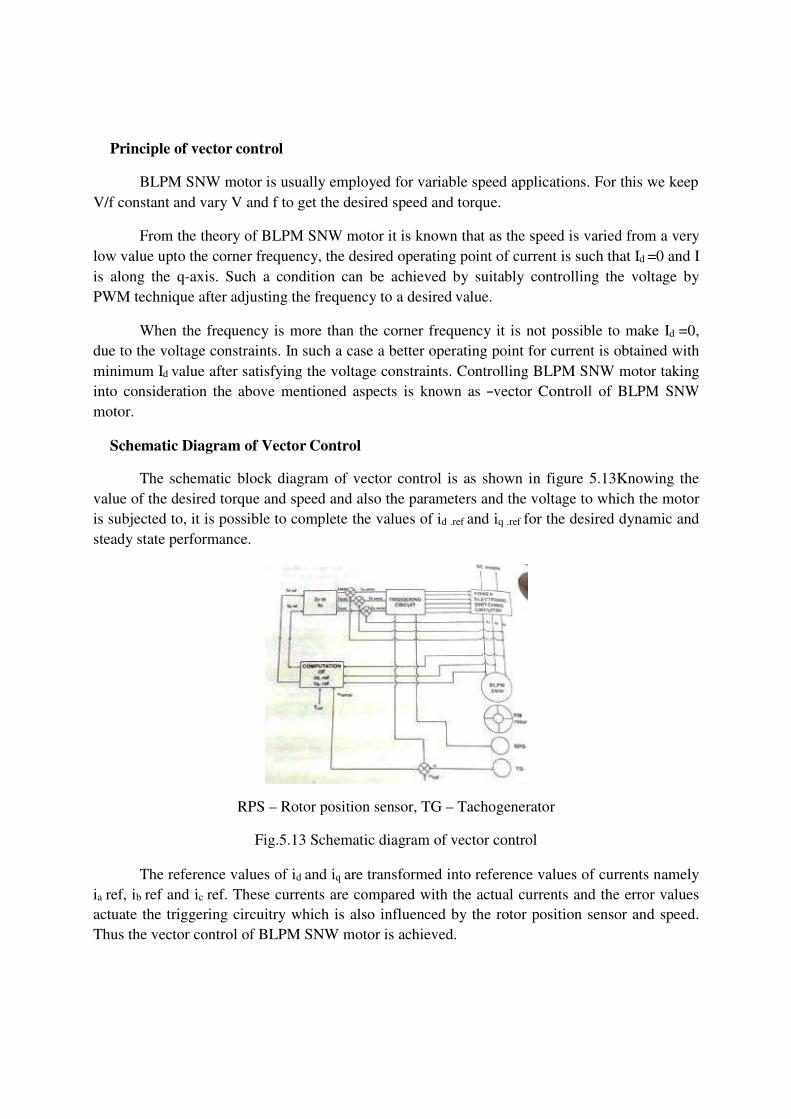
Schematic Diagram of Vector Control
The schematic block diagram of vector control is as shown in figure 5.13Knowing the value of the desired torque and speed and also the parameters and the voltage to which the motor is subjected to, it is possible to complete the values of id .ref and iq .ref for the desired dynamic and steady state performance.
RPS – Rotor position sensor, TG – Tachogenerator
Fig.5.13 Schematic diagram of vector control
The reference values of id and iq are transformed into reference values of currents namely ia ref, ib ref and ic ref. These currents are compared with the actual currents and the error values actuate the triggering circuitry which is also influenced by the rotor position sensor and speed. Thus the vector control of BLPM SNW motor is achieved.
SELF CONTROL OF PMSM
As the rotor speed changes the armature supply frequency is also change proportionally so that the armature field always moves (rotates) at the same speed as the rotor. The armature and rotor field move in synchronism for all operating points. Here accurate tracking of speed by frequency is realized with the help of rotor position sensor.
When the rotor makes certain predetermined angle with the axis of the armature phases the firing pulses to the converter feeding the motor is also change. The switches are fired at a frequency proportional to the motor speed. Thus the frequency of the voltage induced in the armature is proportional to the speed.
Self-control ensures that for all operating points the armature and rotor fields move exactly at the same speed. The torque angle is adjusted electronically hence there is an additional controllable parameter passing greater control of the motor behavior by changing the firing of the semi-conductor switches of an inverter.
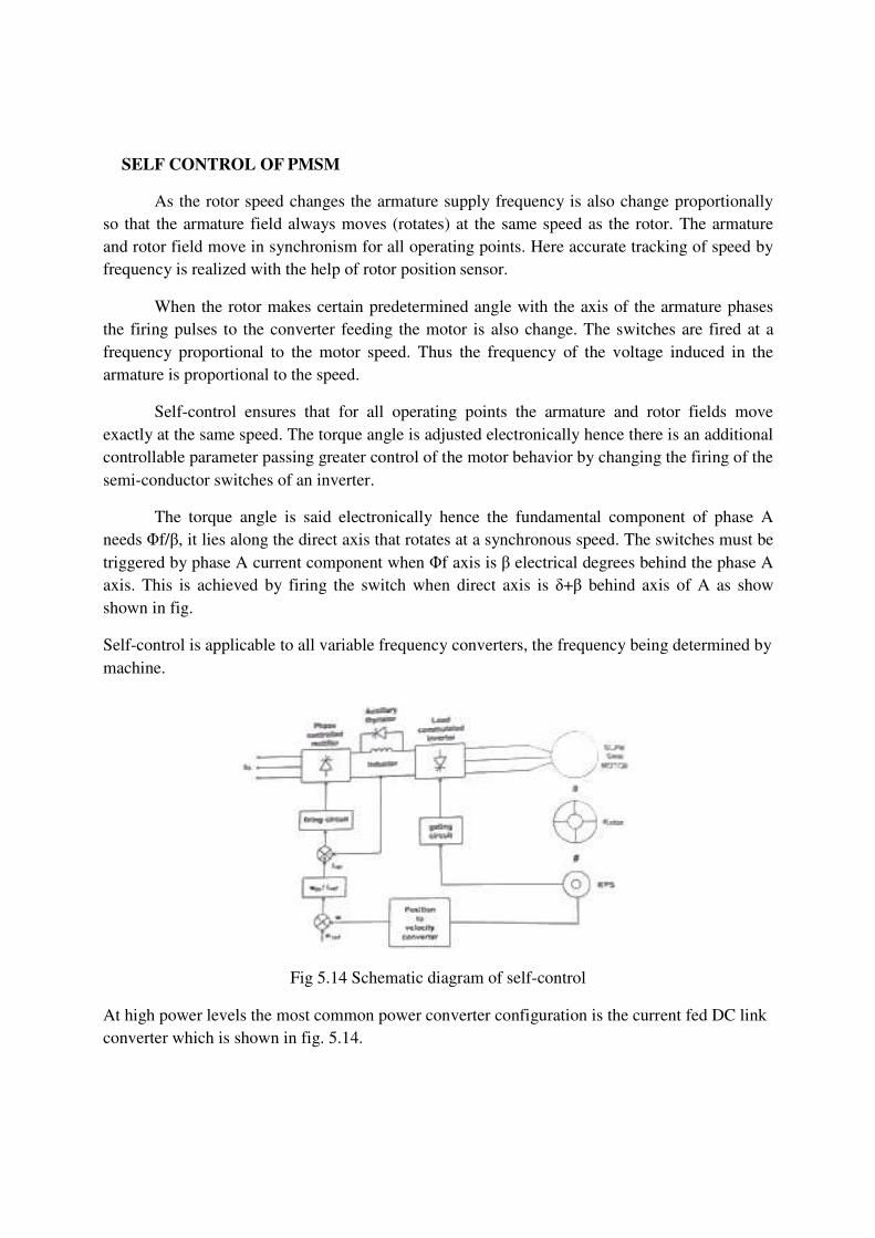
The torque angle is said electronically hence the fundamental component of phase A needs Φf/β, it lies along the direct axis that rotates at a synchronous speed. The switches must be triggered by phase A current component when Φf axis is β electrical degrees behind the phase A axis. This is achieved by firing the switch when direct axis is δ+β behind axis of A as show shown in fig.
Self-control is applicable to all variable frequency converters, the frequency being determined by machine.
Fig 5.14 Schematic diagram of self-control At high power levels the most common power converter configuration is the current fed DC link converter which is shown in fig. 5.14.
Inner current and outer speed loop
The phase controlled thyristor rectifier on the supply side of the DC link has the current regulating loop and operate as a control current source. The regulated DC current is delivered to the DC link inductor to the thyristor of load commutator inverter which supplies line current to the synchronous motor.
The inverter gating signals are under the control of shaft-position sensor giving a commutator less dc motor with armature current controlled. The thyristor of these inverters utilize load commutation because of the generated emf appearing at the armature. It is ensured by the over excitation of synchronous motor, so that it operates at leading power factor hence it reduces commutating circuitry, low losses and is applicable to power levels of several megawatts.
The shaft position is sensed by the position sensor. The shaft speed is obtained by converting the position information. This speed is compared with the reference speed signal which provides the speed error. This is the current reference signal for the linear current loop.
This reference current is compared with the sensed dc link current which provides control signals for the rectifier thyristor. The sensed shaft position is used as gating signal for inverter thyristor.
Commutation at low speed
Load commutation is ensured only at high speeds. Whereas at low speeds the emf generated is not sufficient for load commutation. The inverter can be commutated by supplying pulsating on and off dc link current. This technique produces large pulsating torque but this is not suitable for drives which require smooth torque at low speed.
The DC link current is pulsed by phase shifting the gate signal of the supply side converter from rectification to inversion and back again. When the current is zero the motor side converter is switched to a new conduction period and supply side converter is then turned on. Time required for the motor current to fall to zero can be significantly shortened by placing a shunt thyristor in parallel with a DC link inductor. When the current zero is needed the line side converter is phased back to inversion and the auxiliary thyristor is gated.
The DC link inductor is then short circuited and its current can supply freely without affecting the motor. When the line side converter is turned on the auxiliary thyristor is quickly blocked. This method of interruption of the motor current reduces the effect of pulsating torque.
Four Quadrant Operations
The drive characteristics are similar to those of a conventional DC motor drive. Motor speed can be increased to a certain base speed corresponding to the maximum voltage from the supply. Further, increase in speed is obtained by reducing the field current to give a field weakening region of operation.

Regenerative braking is accomplished by shifting the gate signal, so that machine side inverter acts as a rectifier and supply side rectifier as a inverter, hence the power is return to the ac utility network. The direction of rotation
Of the motor is also reversible by alternating the gate sequence of the motor side converter. Thus four quadrant operations are achieved, without additional circuitry.
5.9 MICROPROCESSOR BASED CONTROL OF PMSE
Fig.5.15 Microprocessor Based Control of PMSM
Fig 5.15 shows the block diagram of microprocessor based permanent magnet synchronous motor drive.
The advent of microprocessor has raised interest in digital control of power converter systems and electronics motor drives since the microprocessor provides a flexible and low cost alternative to the conventional method.
For permanent magnet synchronous motor drive systems, microprocessor control offers several interesting features principally improved performance and reliability, versatility of the controller, reduced components and reduced development and manufacturing cost. In the block diagram of the microprocessor controller PMSM shown in fig 5.15, the permanent magnet synchronous motor is fed from a current source d.c link converter system, which consists of a SCR invertor through rectifier and which is operated from three phase a.c supply lines, and its gating signals are provided by digitally controlled firing circuit.
The optical encoder which is composed of a coded disk attached to the motor shaft and four optical sensors, providing rotor speed and position signals. The invertor triggering pulses are synchronized to the rotor position reference signals with a delay angle determined by an 8-bit control input. The inverter SCR‘s are naturally commutated by the machines voltages during
normal conditions. The speed signals, which is a train of pulses of frequency, proportional to the motor speed, is fed to a programmable counter used for speed sensing.
The stator current is detected by current sensor and amplified by optically isolated amplifier. The output signals are multiplexed and converted to digital form by a high speed analog to digital converter.
The main functions of the microprocessor are monitoring and control of the system variables for the purpose of obtaining desired drive features. It can also perform various auxiliary tasks such as protection, diagnosis and display. In normal operation, commands are fetched from the input-output terminals, and system variables (the dc link current, the rotor position and speed) are sensed and fed to the CPU. After processing, the microprocessor issues control signal to the input rectifier, then the machine inverter, so as to provide the programmed drive characteristics.
Glossary
1. Permanent Magnet Synchronous Motor
-- It is also called as brushless permanent magnet sine wave motor. It has Sinusoidal magnetic flux in the air gap, Sinusoidal current wave forms, and Quasi-sinusoidal distribution stator windings.
2. Flux density -- The intensity of this flux
3. Vector Control -- Also called field-oriented control (FOC), isa variable frequency drive (VFD) control method which controls three-phase AC electric motor
4. Self-Control -- Self-control is the ability to controlone's , behavior, and desires in order to obtain some reward.
5. Peripheral rotor -- The permanent magnets are located on the rotor periphery and permanent magnet flux is radial.
6. Interior rotor -- The permanent magnets are located on the interior of the rotor and flux is generally radial.
7. Resistivity -- Also known as specific resistance, the measure of a material's natural resistance to current flow. Resistivity is the opposite of conductivity, so it follows that good conductors have low resistivity per circular mil foot.
8. Specific Resistance -- Another term for resistivity. Every material has a set specifi
9. Temperature Coefficient
-- A ratio of increased conductor resistance per degree Celsius rise in temperature. Most metals increase in resistance as temperature increases, giving them a positive temperature coefficient.
10. Pole -- One of two ends of the axis of a sphere. Poles also refer to the opposite ends of a magnet.
11. Reluctance -- A material's resistance to becoming magnetized.
12. Residual Magnetism -- The attractive force that exists in an object or substance after it has been removed from a magnetic field