unit 2 motherboard
TRANSCRIPT
8/8/2019 Unit 2 Motherboard
http://slidepdf.com/reader/full/unit-2-motherboard 1/111
Unit 2: Motherboard
Prepared by : Mohd Zuhaimi b Zolkifli
E5164 ± COMPUTER SYSTEM DIAGNOSIS AND MAINTENANCE

8/8/2019 Unit 2 Motherboard
http://slidepdf.com/reader/full/unit-2-motherboard 2/111
Motherboard?
The Motherboard is the main chassis of
the PC.
All data that flows from component tocomponent inside the computer at some
point goes through the motherboard.
That is the Motherboards main function to
direct data flow to the right components.

8/8/2019 Unit 2 Motherboard
http://slidepdf.com/reader/full/unit-2-motherboard 3/111
8/8/2019 Unit 2 Motherboard
http://slidepdf.com/reader/full/unit-2-motherboard 4/111
Function of motherboard main
components
BIOS & CMOS
Sockets
Ports
CPU
Expansion Slot
Buses
Chipset

8/8/2019 Unit 2 Motherboard
http://slidepdf.com/reader/full/unit-2-motherboard 5/111
CPU?
8/8/2019 Unit 2 Motherboard
http://slidepdf.com/reader/full/unit-2-motherboard 6/111
CPU ± Central Processing Unit
The µbrain¶ of computer
The portion of a computer system that
carries out the instructions of a computer program.
Does all the calculations and performs
90% of all the functions of a computer.

8/8/2019 Unit 2 Motherboard
http://slidepdf.com/reader/full/unit-2-motherboard 7/111
Processor Socket/Slot (1)
Sockets are basically flat and have several rows
of holes arranged in a square.
Processor slot is another method of connecting
processor on the motherboard ± but one which
an Intel Pentium II or Pentium III-class processor
on a special expansion card can be inserted.
More complex processor (Intel Itanium) use a
package known as a pin array cartridge (PAC).

8/8/2019 Unit 2 Motherboard
http://slidepdf.com/reader/full/unit-2-motherboard 8/111
8/8/2019 Unit 2 Motherboard
http://slidepdf.com/reader/full/unit-2-motherboard 9/111
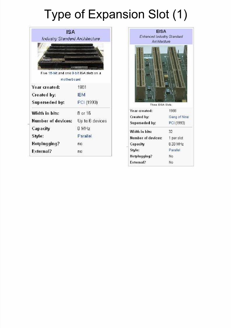
Type of Expansion Slot (1)
8/8/2019 Unit 2 Motherboard
http://slidepdf.com/reader/full/unit-2-motherboard 10/111
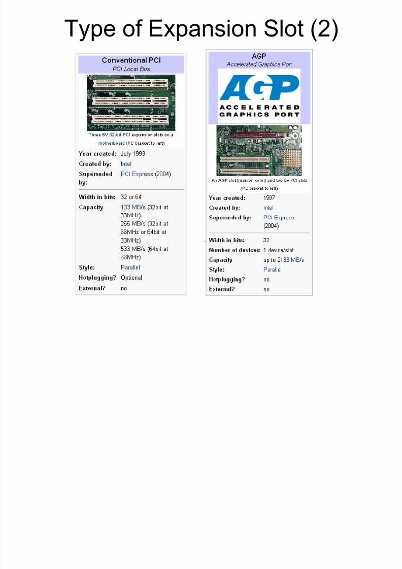
Type of Expansion Slot (2)
8/8/2019 Unit 2 Motherboard
http://slidepdf.com/reader/full/unit-2-motherboard 11/111
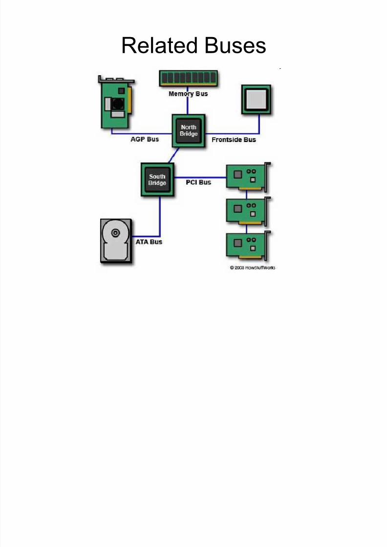
Related Buses
8/8/2019 Unit 2 Motherboard
http://slidepdf.com/reader/full/unit-2-motherboard 12/111

8/8/2019 Unit 2 Motherboard
http://slidepdf.com/reader/full/unit-2-motherboard 13/111
Difference between computer
buses Data width
Cycle rate
To determine the bandwidth, or
the total amount of data that the
bus can transmit.
Device
Management
The maximum number of
supported devices and the
difficulty of configuring them.
TypeTwo types of bus
communications, serial and
parallel.
8/8/2019 Unit 2 Motherboard
http://slidepdf.com/reader/full/unit-2-motherboard 14/111
Front Side Bus - FSB
The FSB is the interface between the CPU and themotherboard, specifically the North Bridge/MemoryController Hub.
Also connects the various hardware components tothe main microprocessor, or central processing unit(CPU).
The FSB is bi-directional, meaning data can flow both
ways, allowing components to send and receive datafrom the CPU.
Speed of FSB is depends on how wide the front sidebus is, its frequency, and the amount of data it canprocess per clock tick of the CPU

8/8/2019 Unit 2 Motherboard
http://slidepdf.com/reader/full/unit-2-motherboard 15/111
FSB - Example

8/8/2019 Unit 2 Motherboard
http://slidepdf.com/reader/full/unit-2-motherboard 16/111
Memory Bus The memory bus is the interface between
the RAM and the motherboard
The memory bus is made up of two parts:
the data bus and the address bus
± Data Bus: which carries actual memory datawithin the PC
± Address Bus: used to select the memoryaddress that the data will come from or go toon a read or write

8/8/2019 Unit 2 Motherboard
http://slidepdf.com/reader/full/unit-2-motherboard 17/111
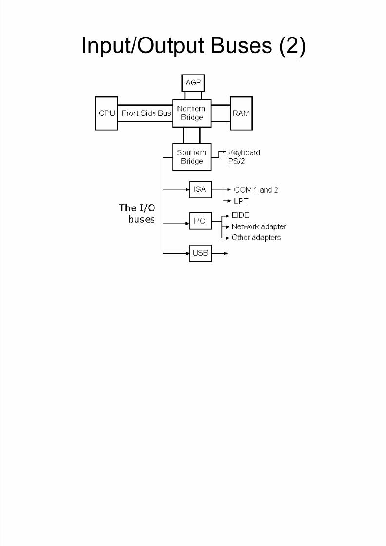
Input/Output Buses (1)
I/O buses connect the CPU to all other components, except RAM.
On modern PCs, usually they are four
buses: ± ISA bus, which is an old low speed bus, soon to be excluded
from the PC design.
± PCI bus, which is a new high speed bus.
± USB bus (Univ ersal Ser i al Bus), which is a new low speed bus.
± AGP bus, which solely is used for the graphics card.
8/8/2019 Unit 2 Motherboard
http://slidepdf.com/reader/full/unit-2-motherboard 18/111
Input/Output Buses (2)
8/8/2019 Unit 2 Motherboard
http://slidepdf.com/reader/full/unit-2-motherboard 19/111
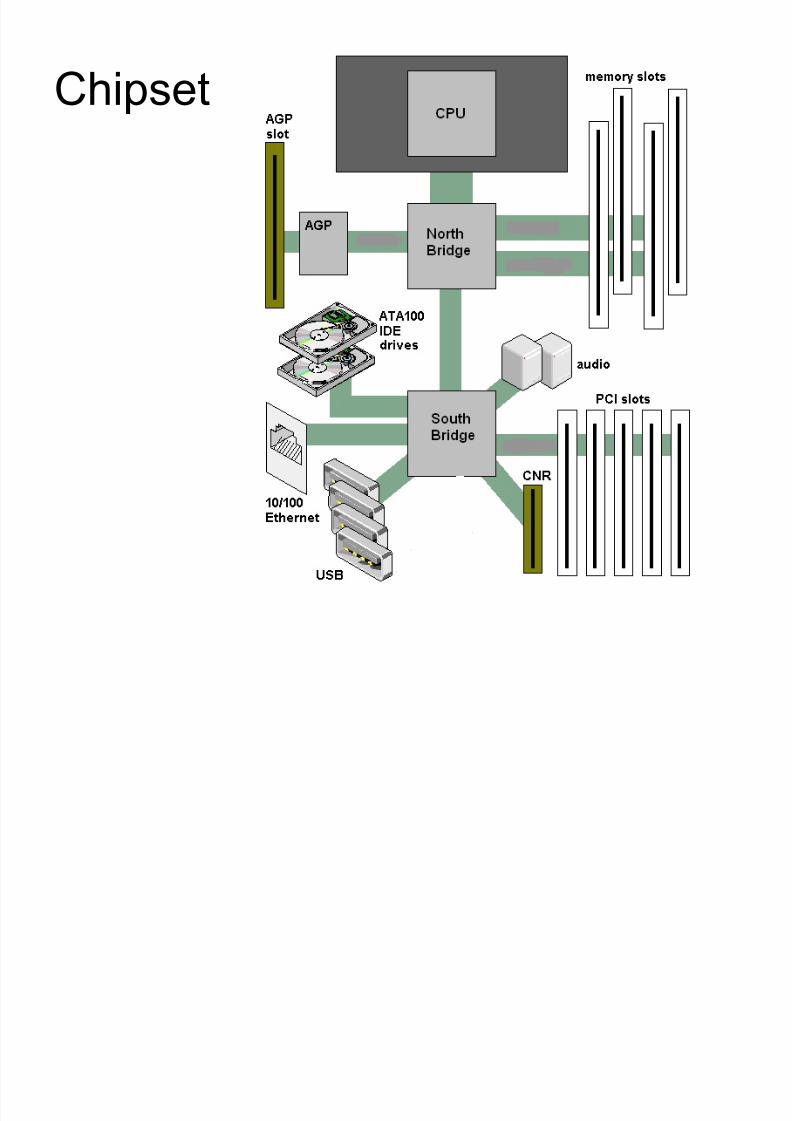
Chipset
8/8/2019 Unit 2 Motherboard
http://slidepdf.com/reader/full/unit-2-motherboard 20/111
What¶s a chipset? A collection of chips or A collection of chips or circuits that perform interface and circuits that perform interface and
peripheral functions for the processor peripheral functions for the processor .
Collection? U sually the circuitry that U sually the circuitry that provides interfaces for memory, expansion provides interfaces for memory, expansion
cards, onboard peripherals and generally cards, onboard peripherals and generally dictates how a motherboard will talk to thedictates how a motherboard will talk to theinstalled peripherals.installed peripherals.
-- Functions of chipset can be divided intoFunctions of chipset can be divided intotwo major functional groups :two major functional groups : NorthbridgeNorthbridgeand and SouthbridgeSouthbridge..

8/8/2019 Unit 2 Motherboard
http://slidepdf.com/reader/full/unit-2-motherboard 21/111
Northbridge
Management of high-speed peripheral
communications.
Responsible for communications with
integrated video using AGP and PCIe, and
processor-to-memory communications .

8/8/2019 Unit 2 Motherboard
http://slidepdf.com/reader/full/unit-2-motherboard 22/111
Southbridge
Responsible for providing support to themyriad onboard peripheral (PS/2, Parallel,IDE etc), managing their communications
with the rest of the computer and theresource given to them.
Also responsible for managingcommunications with the other expansionbuses (PCI, USB and legacy buses).
8/8/2019 Unit 2 Motherboard
http://slidepdf.com/reader/full/unit-2-motherboard 23/111

8/8/2019 Unit 2 Motherboard
http://slidepdf.com/reader/full/unit-2-motherboard 24/111
CMOS(1)
PC has to keep certain setting when it¶sturned off such as:
± Date
± Time
± Hard Drive Configuration
± Memory
PC keeps these settings in a specialmemory chip called the ComplimentaryMetal Oxide Semiconductor (CMOS) chip.

8/8/2019 Unit 2 Motherboard
http://slidepdf.com/reader/full/unit-2-motherboard 25/111
CMOS(2)
To keep it setting, the memory must have
power constantly.
Motherboard manufacturers include asmall battery called CMOS Battery to
power the CMOS memory.

8/8/2019 Unit 2 Motherboard
http://slidepdf.com/reader/full/unit-2-motherboard 26/111
Socket (1)
IDE Socket
± Usually use to
connect hard
drive, CD-RW,
DVD etc. JTAG IDE Socket
IDE Connector

8/8/2019 Unit 2 Motherboard
http://slidepdf.com/reader/full/unit-2-motherboard 27/111
Socket (2)
SIMM Socket
± holds a single
SIMM
± SIMM (single in-
line memory
module )

8/8/2019 Unit 2 Motherboard
http://slidepdf.com/reader/full/unit-2-motherboard 28/111
Socket (3)
DIMM Socket
± Usually use for
DRAM, SDRAM,
non-standard DRAMmodule etc
± DIMM - Dual in-line
memory module,
comprises a series of
dynamic random
access memory
integrated circuits

8/8/2019 Unit 2 Motherboard
http://slidepdf.com/reader/full/unit-2-motherboard 29/111
Socket (4)
FDD Socket
± used for floppy disk
drives.
8/8/2019 Unit 2 Motherboard
http://slidepdf.com/reader/full/unit-2-motherboard 30/111
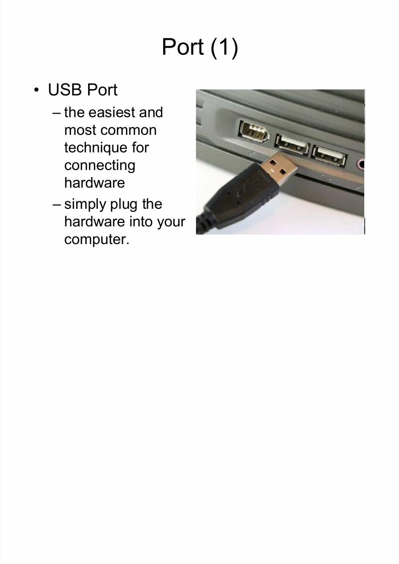
Port (1)
USB Port
± the easiest and
most common
technique for
connecting
hardware
± simply plug thehardware into your
computer.
8/8/2019 Unit 2 Motherboard
http://slidepdf.com/reader/full/unit-2-motherboard 31/111
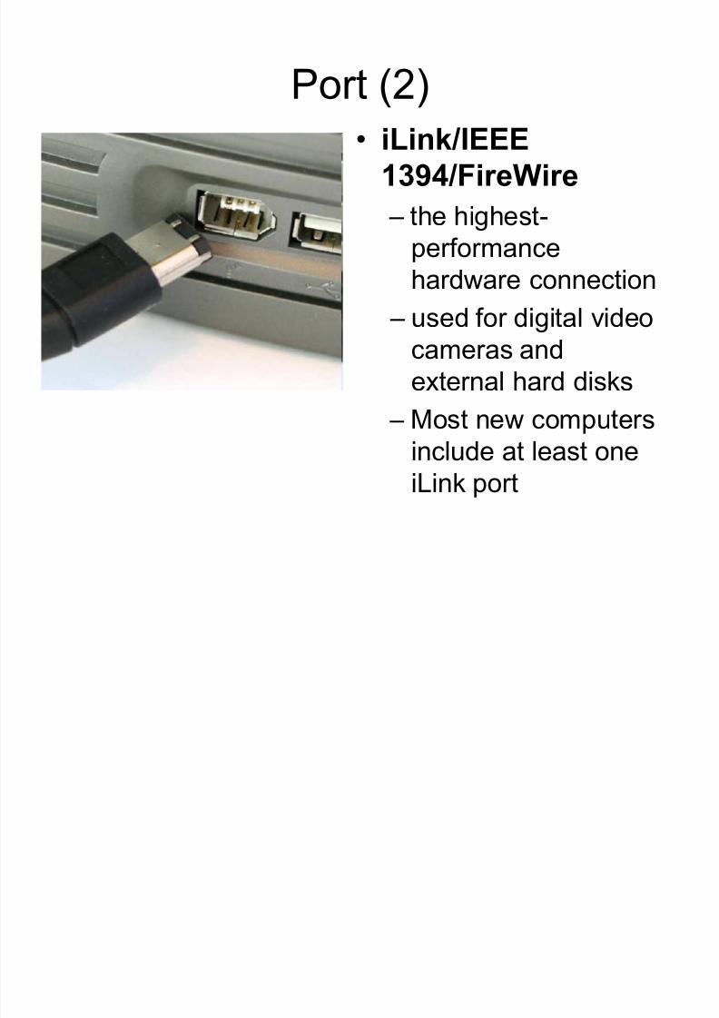
Port (2)
iLink/IEEE 1394/FireWire
± the highest-
performancehardware connection
± used for digital video
cameras and
external hard disks ± Most new computers
include at least one
iLink port
8/8/2019 Unit 2 Motherboard
http://slidepdf.com/reader/full/unit-2-motherboard 32/111
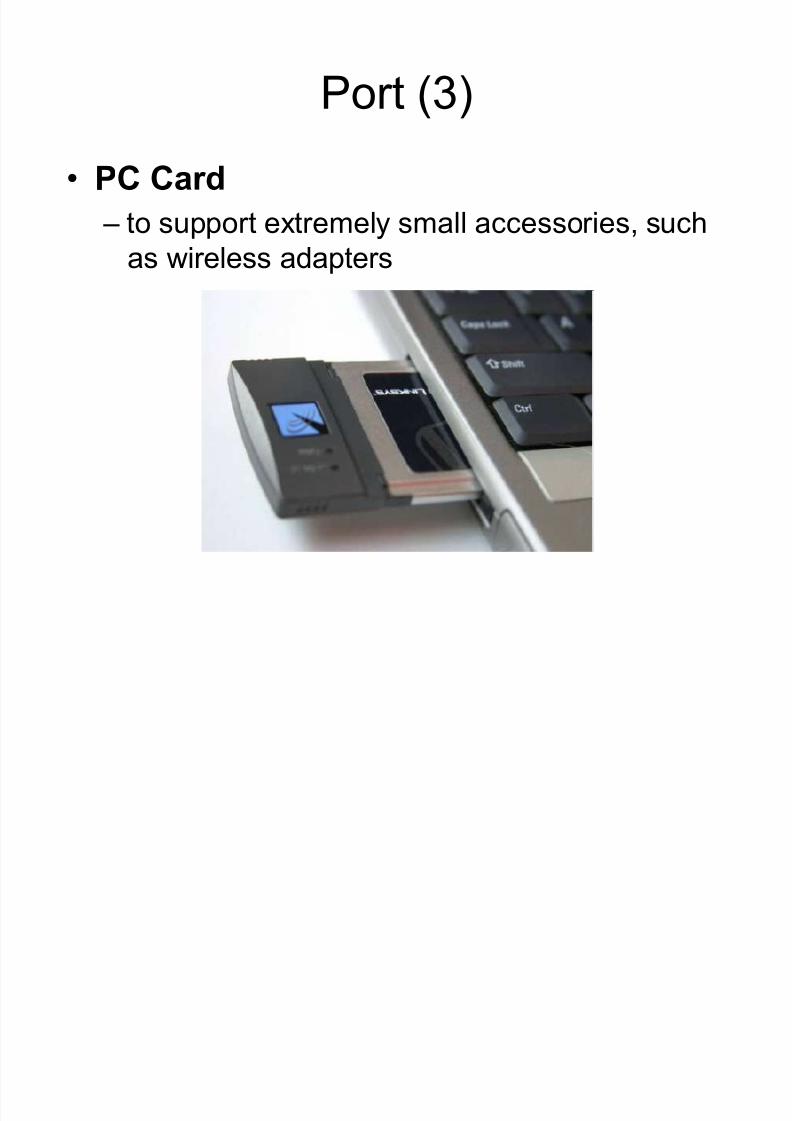
Port (3)
PC Card
± to support extremely small accessories, such
as wireless adapters
8/8/2019 Unit 2 Motherboard
http://slidepdf.com/reader/full/unit-2-motherboard 33/111
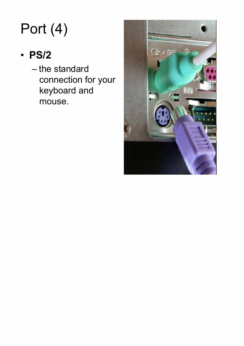
Port (4)
PS /2
± the standard
connection for your
keyboard and
mouse.
8/8/2019 Unit 2 Motherboard
http://slidepdf.com/reader/full/unit-2-motherboard 34/111
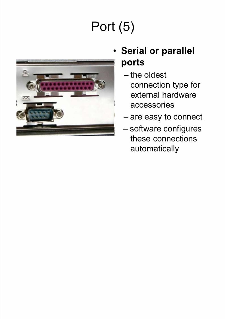
Port (5)
Serial or parallel
ports
± the oldest
connection type for
external hardware
accessories
± are easy to connect ± software configures
these connections
automatically

8/8/2019 Unit 2 Motherboard
http://slidepdf.com/reader/full/unit-2-motherboard 35/111
Main Memory
8/8/2019 Unit 2 Motherboard
http://slidepdf.com/reader/full/unit-2-motherboard 36/111
Introduction
Also known as RAM ( Random Access Memory)
Needs to have electrical power in order to
maintain its information (W hen power is lost, theinformation is lost too!)
It can be directly accessed by the CPU
Main memory is expensive compared to
external memory so it has limited capacity
8/8/2019 Unit 2 Motherboard
http://slidepdf.com/reader/full/unit-2-motherboard 37/111
How it work?
A memory chip is an integrated circuit(IC) made of millions of transistors andcapacitors.
A transistor and a capacitor are paired tocreate a memory cell, which represents asingle bit of data. (in DRAM )
The capacitor holds the bit of information. The transistor acts as a switch that lets the
control circuitry on the memory chip readthe capacitor or change its state.

8/8/2019 Unit 2 Motherboard
http://slidepdf.com/reader/full/unit-2-motherboard 38/111

8/8/2019 Unit 2 Motherboard
http://slidepdf.com/reader/full/unit-2-motherboard 39/111
Memory Organisation
Magnetictapes
Magneticdisks
I /Oprocessor
CPU
Mainmemory
Cachememory
Auxiliary memory
Register
Cache
Main Memory
Magnetic Disk
Magnetic Tape

8/8/2019 Unit 2 Motherboard
http://slidepdf.com/reader/full/unit-2-motherboard 40/111
8/8/2019 Unit 2 Motherboard
http://slidepdf.com/reader/full/unit-2-motherboard 41/111
8/8/2019 Unit 2 Motherboard
http://slidepdf.com/reader/full/unit-2-motherboard 42/111
Memory Packaging
The memory slots on the motherboard are
designed for particular module form
factors or styles.
DIP, SIMM and SIPP are obsolete
memory packages.
The most popular form factors for primary
memory modules today are DIMM, RIMM,
SoDIMM and MicroDIMM
8/8/2019 Unit 2 Motherboard
http://slidepdf.com/reader/full/unit-2-motherboard 43/111
Memory Module ± SIMM (1)
Single in-line memory module
containing random access memory used incomputers from the early 1980s to the late 1990s
DRAM technologies used in SIMMs include EDOand FPM.
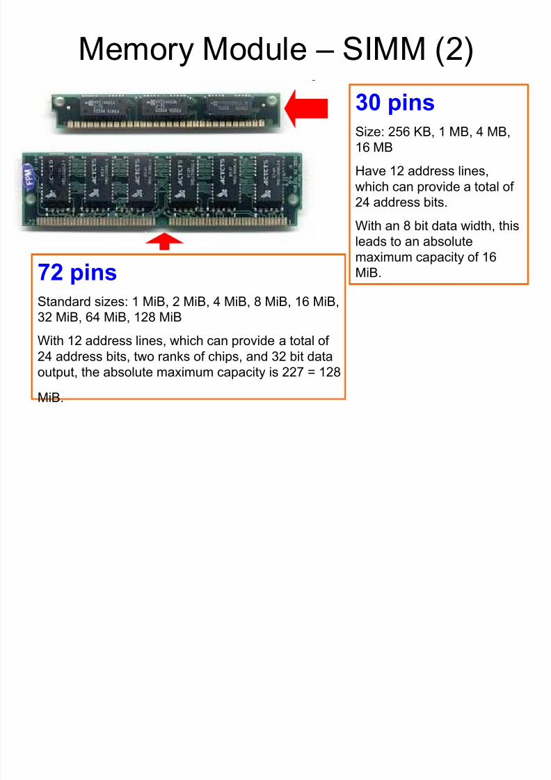
The first variant of SIMMs has 30 pins andprovides 9 bits of data.
The second variant of SIMMs has 72 pins andprovides 32 bits of data (36 bits in parity versions)
8/8/2019 Unit 2 Motherboard
http://slidepdf.com/reader/full/unit-2-motherboard 44/111
8/8/2019 Unit 2 Motherboard
http://slidepdf.com/reader/full/unit-2-motherboard 45/111
Memory Module ± DIMM (1)
Dual In-line Memory Module
comprises a series of dynamic random
access memory integrated circuits. 64-bit memory modules that are used as a
package for the SDRAM family (SDRAM,
DDR and DDR2.
DIMM differentiate the functionality of the
pins on one side of the module from the
corresponding pins on the other side.
8/8/2019 Unit 2 Motherboard
http://slidepdf.com/reader/full/unit-2-motherboard 46/111
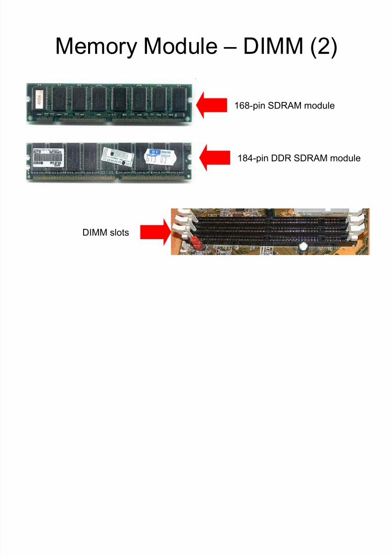
Memory Module ± DIMM (2)
168-pin SDRAM module
184-pin DDR SDRAM module
DIMM slots

8/8/2019 Unit 2 Motherboard
http://slidepdf.com/reader/full/unit-2-motherboard 47/111
Memory Module ± DIMM (3)
DIMM range in capacity from 8 MB to 1
GB per module and can be installed singly
instead of in pairs.
Another standard, Rambus in-line
memory module (RIMM), is comparable
in size and pin configuration to DIMM but
uses a special memory bus to greatlyincrease speed.

8/8/2019 Unit 2 Motherboard
http://slidepdf.com/reader/full/unit-2-motherboard 48/111
Memory Module ± SODIMM (1)
Many brands of notebook computers useproprietary memory modules, but severalmanufacturers use RAM based on the smalloutline dual in-line memory module(SODIMM) configuration.
SODIMM cards are small, about 2 x 1 inch (5 x2.5 cm), and have 144 or 200 pins.
Capacity ranges from 16 MB to 1 GB per module.
Sub-notebook computers use even smaller DIMMs, known as MicroDIMMs, which haveeither 144 pins or 172 pins.

8/8/2019 Unit 2 Motherboard
http://slidepdf.com/reader/full/unit-2-motherboard 49/111
Memory Module ± SODIMM (2)
8/8/2019 Unit 2 Motherboard
http://slidepdf.com/reader/full/unit-2-motherboard 50/111
Type Of Memory (DRAM)
Dynamic random access memory
Has memory cells with a paired
transistor and capacitor requiringconstant refreshing.

8/8/2019 Unit 2 Motherboard
http://slidepdf.com/reader/full/unit-2-motherboard 51/111
Type Of Memory (SRAM)
Static random access memory
Uses multiple transistors, typically four to
six, for each memory cell but doesn't havea capacitor in each cell. It is used primarily
for cache.

8/8/2019 Unit 2 Motherboard
http://slidepdf.com/reader/full/unit-2-motherboard 52/111
Type Of Memory (FPM DRAM)
Fast page mode dynamic random
access memory
It waits through the entire process of locating a bit of data by column and row.
Then reading the bit before it starts on the
next bit.
Maximum transfer rate to L2 cache is
approximately 176 MBps.

8/8/2019 Unit 2 Motherboard
http://slidepdf.com/reader/full/unit-2-motherboard 53/111
Type Of Memory (VideoRAM)
A type of RAM used specifically for videoadapters or 3D accelerators.
VRAM normally has two independent access
ports allowing the CPU and graphics processor to access the RAM simultaneously.
VRAM is located on the graphics card andcomes in a variety of formats.
The amount of VRAM is a determining factor inthe resolution and color depth of the display.
VRAM is also used to hold graphics-specificinformation such as 3-D geometry data and
texture maps.

8/8/2019 Unit 2 Motherboard
http://slidepdf.com/reader/full/unit-2-motherboard 54/111
Type Of Memory (EDO DRAM)
Extended data-out dynamic randomaccess memory
Does not wait for all of the processing of
the first bit before continuing to the nextone.
As soon as the address of the first bit is
located, EDO DRAM begins looking for thenext bit.
It is about five percent faster than FPM.Maximum transfer rate to L2 cache is
approximately 264 MBps.

8/8/2019 Unit 2 Motherboard
http://slidepdf.com/reader/full/unit-2-motherboard 55/111
Type Of Memory (SDRAM)
Synchronous dynamic random accessmemory
Takes advantage of the burst mode concept togreatly improve performance.
It does this by staying on the row containing therequested bit and moving rapidly through thecolumns, reading each bit as it goes.
The idea is that most of the time the data
needed by the CPU will be in sequence. SDRAM is about five percent faster than EDO
RAM and is the most common form in desktopstoday. Maximum transfer rate to L2 cache is
approximately 528 MBps.

8/8/2019 Unit 2 Motherboard
http://slidepdf.com/reader/full/unit-2-motherboard 56/111
Memory bank system

8/8/2019 Unit 2 Motherboard
http://slidepdf.com/reader/full/unit-2-motherboard 57/111
How memory load onto
motherboard
8/8/2019 Unit 2 Motherboard
http://slidepdf.com/reader/full/unit-2-motherboard 58/111
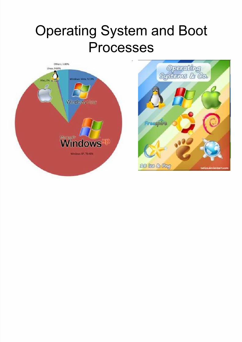
Operating System and Boot
Processes
8/8/2019 Unit 2 Motherboard
http://slidepdf.com/reader/full/unit-2-motherboard 59/111
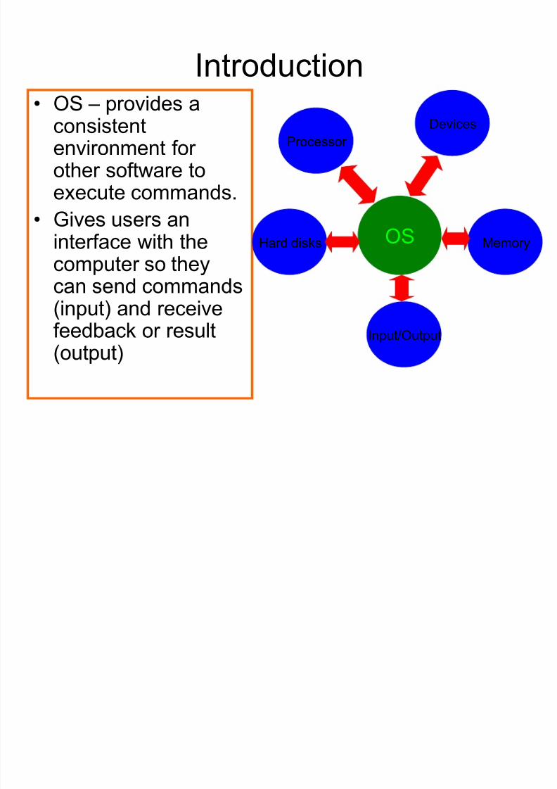
Introduction
OS ± provides aconsistentenvironment for other software to
execute commands. Gives users an
interface with thecomputer so theycan send commands(input) and receivefeedback or result(output)
OS
Processor
Devices
Hard disks Memory
Input/Output
8/8/2019 Unit 2 Motherboard
http://slidepdf.com/reader/full/unit-2-motherboard 60/111
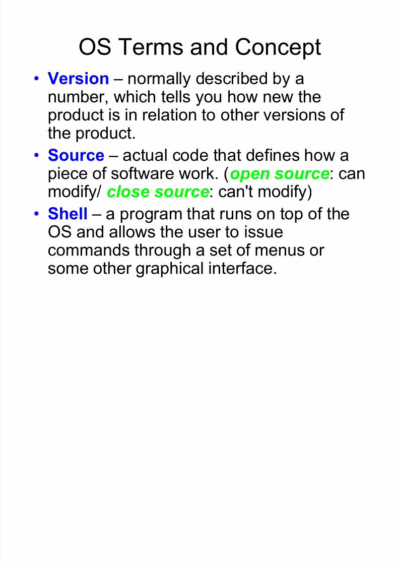
OS Terms and Concept
Version ± normally described by anumber, which tells you how new theproduct is in relation to other versions of the product.
Source ± actual code that defines how apiece of software work. (open source: canmodify/ cl ose source: can't modify)
Shell ± a program that runs on top of theOS and allows the user to issuecommands through a set of menus or some other graphical interface.

8/8/2019 Unit 2 Motherboard
http://slidepdf.com/reader/full/unit-2-motherboard 61/111
Graphical User Interface (GUI) ± a method
by which a person communicates with a
computer. Network ± any group of computer that have a
communication link between them.
Cooperative Multitasking ± a multitaskingmethod that depends on the application itself
to be responsible for using and then freeing
access to the processor.

8/8/2019 Unit 2 Motherboard
http://slidepdf.com/reader/full/unit-2-motherboard 62/111
Preemptive Multitasking ± a multitasking
method in which OS allots each
application a certain amount of processor time and then forcibly takes back control
and gives another application or task
access to the processor. Multithreading ± ability of a single
application to have multiple requests in to
the processor at one time.
8/8/2019 Unit 2 Motherboard
http://slidepdf.com/reader/full/unit-2-motherboard 63/111
8/8/2019 Unit 2 Motherboard
http://slidepdf.com/reader/full/unit-2-motherboard 64/111

8/8/2019 Unit 2 Motherboard
http://slidepdf.com/reader/full/unit-2-motherboard 65/111
8/8/2019 Unit 2 Motherboard
http://slidepdf.com/reader/full/unit-2-motherboard 66/111

8/8/2019 Unit 2 Motherboard
http://slidepdf.com/reader/full/unit-2-motherboard 67/111
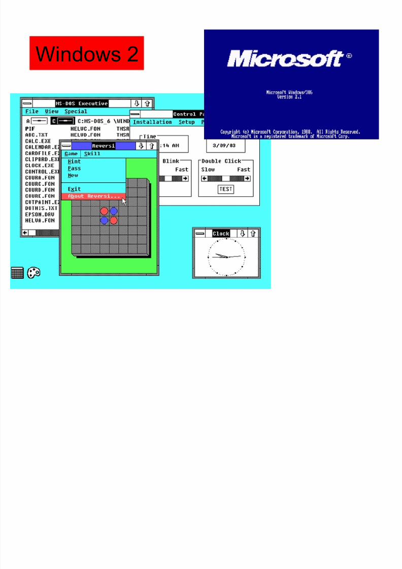
Windows 2.0 - 1987
Added icons and allowed application
windows to overlap each other, as well as
tile.
Support was also added for PIFs (program
information files), which allowed the user
to configures Windows to run their DOS
applications more efficiently.
8/8/2019 Unit 2 Motherboard
http://slidepdf.com/reader/full/unit-2-motherboard 68/111
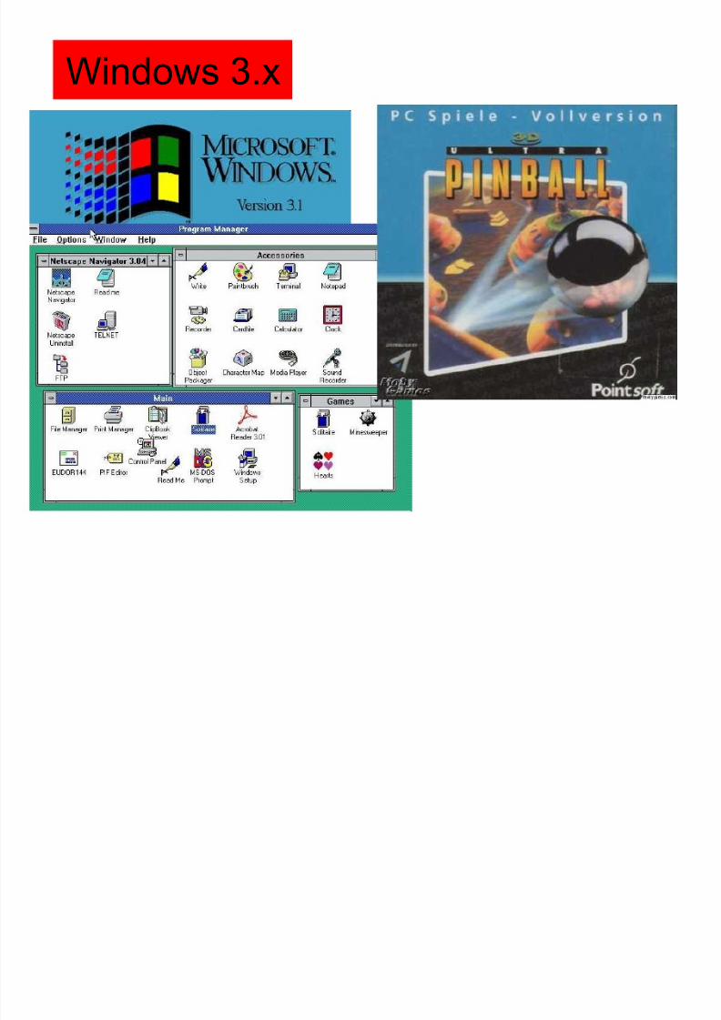
Windows 3.x
8/8/2019 Unit 2 Motherboard
http://slidepdf.com/reader/full/unit-2-motherboard 69/111
Windows 3.x ± 1990an
A far more flexible memory model ( more
than 640kb ± normally imposed by DOS)
The addition of the File Manager and
Program Manager
Allowed for network support.
Could operate in 386 Enhanced mode( used part of the hard drive as virtual memory ±able to use disk memory to supplement the RAM
in the machine.)

8/8/2019 Unit 2 Motherboard
http://slidepdf.com/reader/full/unit-2-motherboard 70/111
8/8/2019 Unit 2 Motherboard
http://slidepdf.com/reader/full/unit-2-motherboard 71/111
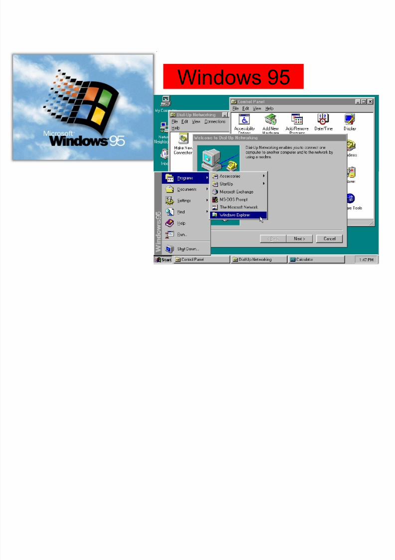
Windows 95

8/8/2019 Unit 2 Motherboard
http://slidepdf.com/reader/full/unit-2-motherboard 72/111
8/8/2019 Unit 2 Motherboard
http://slidepdf.com/reader/full/unit-2-motherboard 73/111
Windows 98/Me/NT/2000/XP
Wi d 98/M /NT/2000/XP

8/8/2019 Unit 2 Motherboard
http://slidepdf.com/reader/full/unit-2-motherboard 74/111
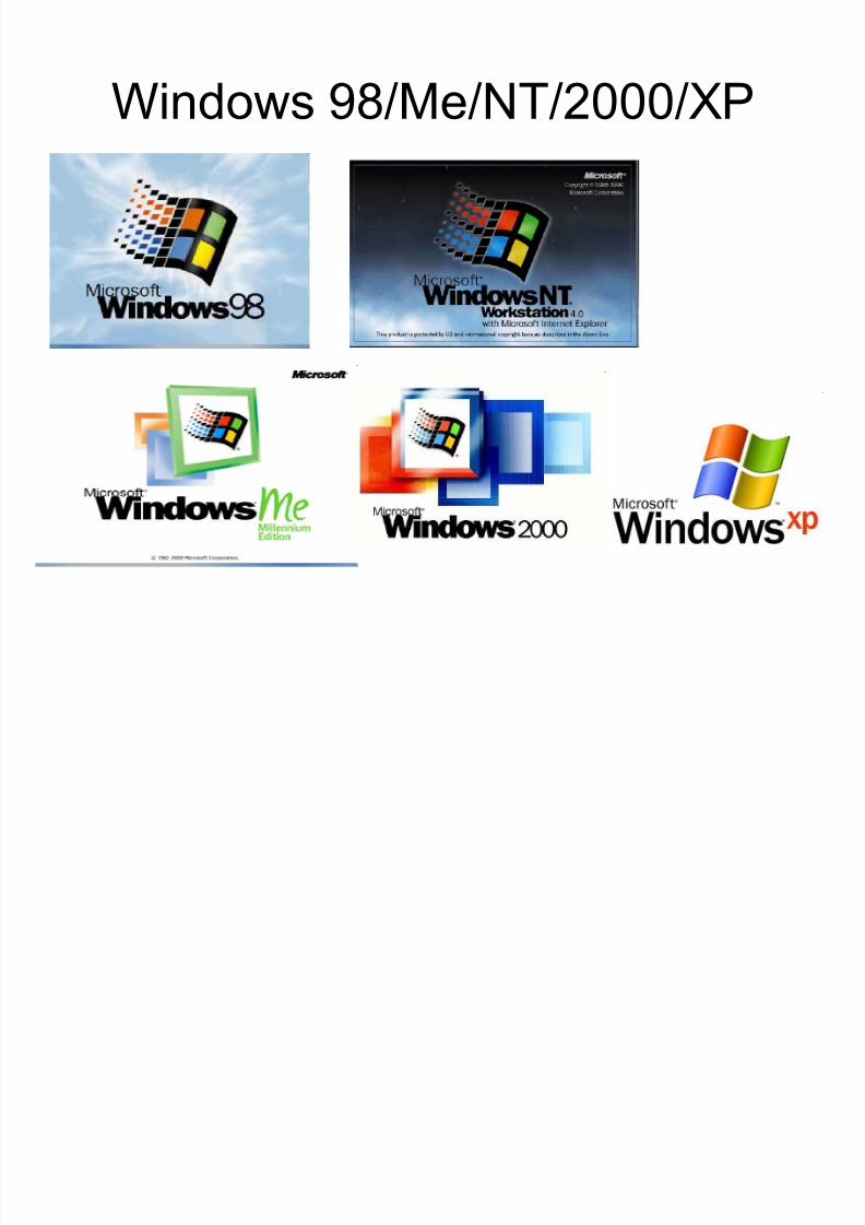
Windows 98/Me/NT/2000/XP
Windows 98/Me released after 95. Then Windows NT ± designed to be far more
powerful, uses an architecture based entirelyon 32-bit code and is capable of accessing upto 4GB of RAM.
Then Windows 2000 ± used the sameinterface as Windows 98 with a few important
enhancement. Windows XP ± come in 3 version (X P Home,
X P Professional and Media Center), containsmore corporate and network features.
8/8/2019 Unit 2 Motherboard
http://slidepdf.com/reader/full/unit-2-motherboard 75/111
8/8/2019 Unit 2 Motherboard
http://slidepdf.com/reader/full/unit-2-motherboard 76/111
Boot Process
Supplying Power
Bootstrap
Core Test POST
OS Search
Loading OS

8/8/2019 Unit 2 Motherboard
http://slidepdf.com/reader/full/unit-2-motherboard 77/111
Supplying Power
The internal power supply turns on andinitializes.
The power supply takes some time until it
can generate reliable power for the rest of the computer, and having it turn onprematurely could potentially lead todamage.
Therefore, the chipset will generate a resetsignal to the processor until it receives thePower Good signal from the power supply.
8/8/2019 Unit 2 Motherboard
http://slidepdf.com/reader/full/unit-2-motherboard 78/111
8/8/2019 Unit 2 Motherboard
http://slidepdf.com/reader/full/unit-2-motherboard 79/111
Power-on self-test (POST)
It is the first step of the more general
process called initial program load (IPL),
booting, or bootstrapping.
On power up, the main duties of POST
are handled by the BIOS, which may hand
some of these duties to other programs
designed to initialize very specificperipheral devices, notably for video and
SCSI initialization.
P i i l d ti f th i BIOS

8/8/2019 Unit 2 Motherboard
http://slidepdf.com/reader/full/unit-2-motherboard 80/111
Principal duties of the main BIOS
during POST Verify the integrity of the BIOS code itself Find, size, and verify system main memory
Discover, initialize, and catalog all system busesand devices
Pass control to other specialized BIOSes (if andwhen required)
Provide a user interface for system'sconfiguration
Identify, organize, and select which devices areavailable for booting
Construct whatever system environment that isrequired by the target OS

8/8/2019 Unit 2 Motherboard
http://slidepdf.com/reader/full/unit-2-motherboard 81/111
POST beeps code
Beeps Meaning
Steady, short beeps Power supply may be bad
Long continuousbeeps
Memory failure
Steady, long beeps Power supply bad
No Beeps Power supply bad, system not plugged in, or power not turned on
One long, two short
beeps
Video card failure

8/8/2019 Unit 2 Motherboard
http://slidepdf.com/reader/full/unit-2-motherboard 82/111
1st stage of typical POST
2nd stage of a POST
Boot Process of DOS Operating

8/8/2019 Unit 2 Motherboard
http://slidepdf.com/reader/full/unit-2-motherboard 83/111
Boot Process of DOS Operating
System
1. Once the computer system is turned on,the BIOS performs a series of activitiescalled POST that checks to see whether the peripherals in the system are inperfect order.
2. This Pre Boot Sequence consists of a
series of steps that starts with theexecution of software stored in the ROMcalled firmware.
8/8/2019 Unit 2 Motherboard
http://slidepdf.com/reader/full/unit-2-motherboard 84/111
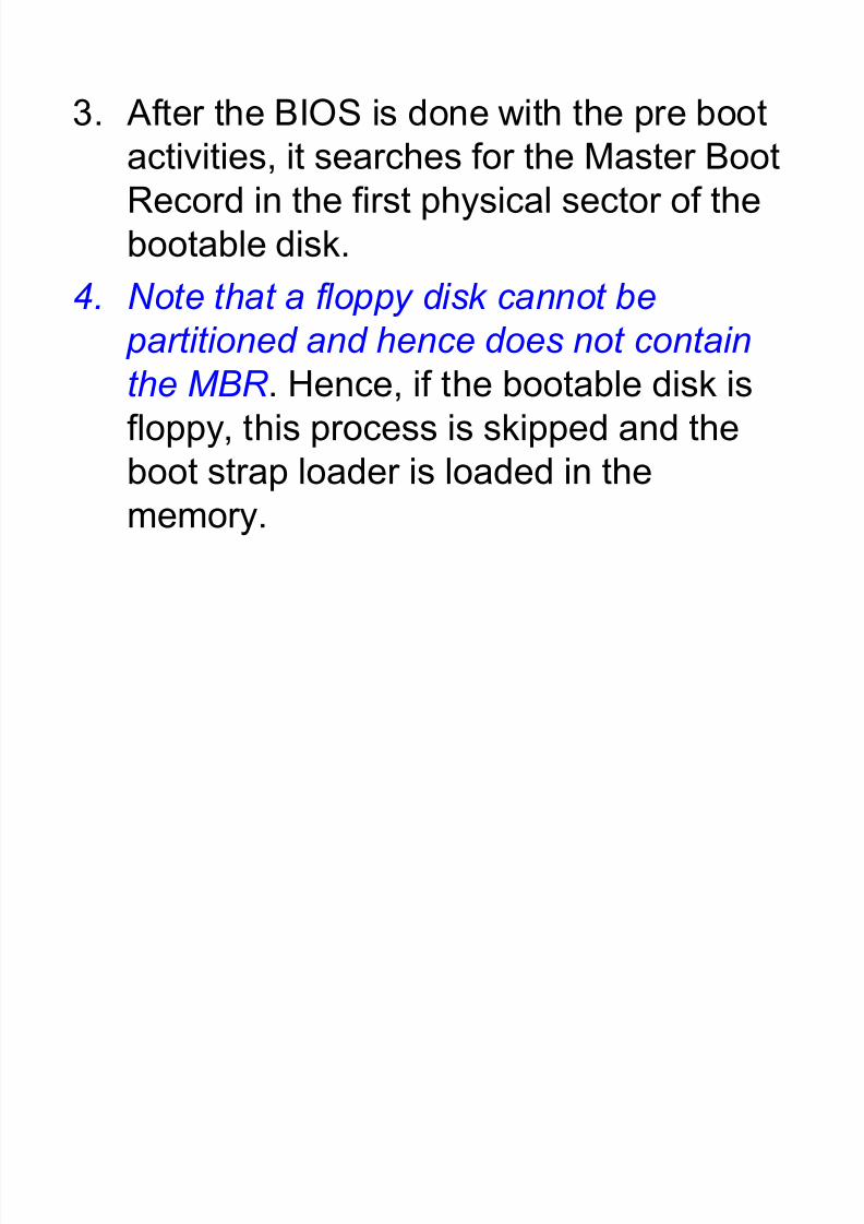
3. After the BIOS is done with the pre boot
activities, it searches for the Master BootRecord in the first physical sector of the
bootable disk.
4. Note that a floppy disk cannot be
partitioned and hence does not contain
the MBR . Hence, if the bootable disk is
floppy, this process is skipped and the
boot strap loader is loaded in thememory.
8/8/2019 Unit 2 Motherboard
http://slidepdf.com/reader/full/unit-2-motherboard 85/111
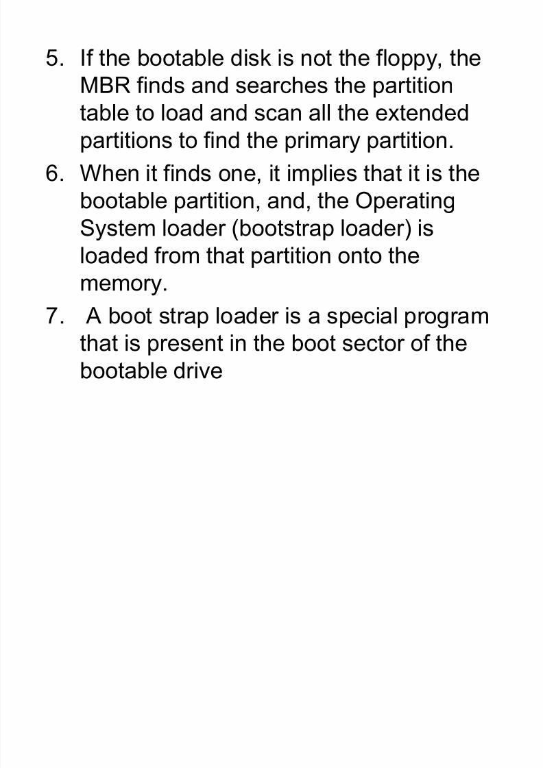
5. If the bootable disk is not the floppy, the
MBR finds and searches the partition
table to load and scan all the extended
partitions to find the primary partition.
6. When it finds one, it implies that it is the
bootable partition, and, the OperatingSystem loader (bootstrap loader) is
loaded from that partition onto the
memory.7. A boot strap loader is a special program
that is present in the boot sector of the
bootable drive
8 MS DOS Operating system comprises

8/8/2019 Unit 2 Motherboard
http://slidepdf.com/reader/full/unit-2-motherboard 86/111
8. MS DOS Operating system comprises
of the following files: ---
IO.Sys
MSDOS.Sys
Command.Com
Config.SysAutoexec.bat
Mandatory
Should be present in the
bootable drive
If not found, then the
message,"Non-system
disk or disk error -
Replace and press any
key when ready"
Optional
9. The boot strap loader first loads the IO.Sys file.
8/8/2019 Unit 2 Motherboard
http://slidepdf.com/reader/full/unit-2-motherboard 87/111
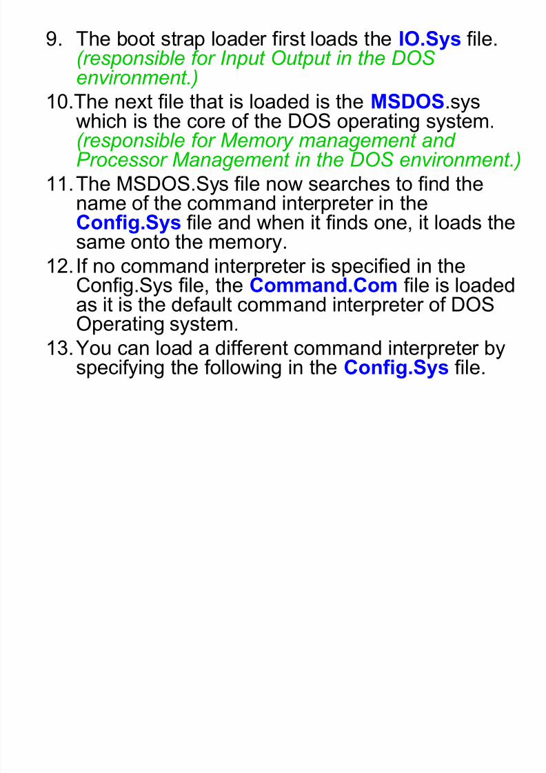
9. The boot strap loader first loads the IO.Sys file.( responsible for Input Output in the DOS environment.)
10.The next file that is loaded is the MSDOS.syswhich is the core of the DOS operating system.( responsible for Memory management and Processor Management in the DOS environment.)
11.The MSDOS.Sys file now searches to find the
name of the command interpreter in theConfig.Sys file and when it finds one, it loads thesame onto the memory.
12. If no command interpreter is specified in the
Config.Sys file, the Command.Com file is loadedas it is the default command interpreter of DOSOperating system.
13.You can load a different command interpreter byspecifying the following in the Config.Sys file.
14 Th l t fil t b l d d d t d i
8/8/2019 Unit 2 Motherboard
http://slidepdf.com/reader/full/unit-2-motherboard 88/111
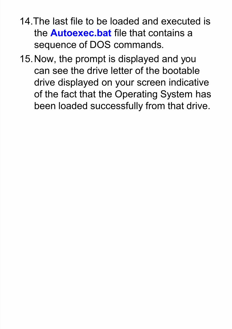
14.The last file to be loaded and executed is
the Autoexec.bat file that contains a
sequence of DOS commands.15.Now, the prompt is displayed and you
can see the drive letter of the bootable
drive displayed on your screen indicativeof the fact that the Operating System has
been loaded successfully from that drive.
8/8/2019 Unit 2 Motherboard
http://slidepdf.com/reader/full/unit-2-motherboard 89/111
Boot Disc
What?
± A boot disk will allow you to boot off of a
diskette instead of your hard drive. This
diskette can be used to fix issues that may
arise during the lifetime of your computer.

8/8/2019 Unit 2 Motherboard
http://slidepdf.com/reader/full/unit-2-motherboard 90/111
Creating a Window XP boot disk
The Microsoft Windows XP CD is a
bootable CD and in many cases you
should not need a bootable floppy
diskette. Booting from the Windows XPCD will allow you to not only install/re-
install Windows XP but will also allow you
to troubleshoot it.

8/8/2019 Unit 2 Motherboard
http://slidepdf.com/reader/full/unit-2-motherboard 91/111
Important file in Boot Disc
Boot.ini - which contains configuration
options for a boot menu.
NTLDR - which contains the main Boot
loader itself
Ntdetect.com - To load an NT-based OS
(NTLDR is actually required. If boot.ini is missing, NTLDRwill default to \Windows on the first partition of the first harddrive. Many desktops in the home are in this configurationand a missing boot.ini file will simply generate an error stating it is missing, then boot into Windows successfully.)
Create MS-DOS bootable

8/8/2019 Unit 2 Motherboard
http://slidepdf.com/reader/full/unit-2-motherboard 92/111
Create MS-DOS bootable
diskette
When formatting a floppy diskette, users have the
option of creating a MS-DOS startup disk,
follow the below steps to do this.
1. Place diskette in the computer.2. Open My Computer, right-click the A: drive and
click Format.
3. In the Format window, check Create an MS-
DOS startup disk.
4. Click Start
8/8/2019 Unit 2 Motherboard
http://slidepdf.com/reader/full/unit-2-motherboard 93/111
How to use a boot diskette
1. Place the diskette into write-protect mode (incase a virus is on the computer, this will notallow the virus to transfer itself onto thediskette).
2. Insert the diskette into the computer and resetor turn on the computer to begin the bootprocess.
3. As the computer is booting, answer thequestions prompted (if any).
4. Once at the A:\> take the appropriate actionsdepending upon the situation of the computer.

8/8/2019 Unit 2 Motherboard
http://slidepdf.com/reader/full/unit-2-motherboard 94/111
Resources System
Interrupt Request (IRQ)
DMA Channel
I/O Addresses

8/8/2019 Unit 2 Motherboard
http://slidepdf.com/reader/full/unit-2-motherboard 95/111
Interrupt Requests (IRQ)
What? IRQ manage various hardwareoperations. Devices such as sound cards,modems, and keyboards can all sendinterrupt requests to the processor.
Example: when the modem needs to run aprocess, it sends an interrupt request tothe CPU saying, "Hey, hold up, let me do
my thing!" The CPU then interrupts itscurrent job to let the modem run itsprocess.
IRQ (2)
8/8/2019 Unit 2 Motherboard
http://slidepdf.com/reader/full/unit-2-motherboard 96/111
IRQ (2) It is important to assign different IRQ addresses to
different hardware devices - the interrupt requestsignals run along single IRQ lines to a controller.
This interrupt controller assigns priorities to incomingIRQs and sends them to the CPU.
Since the interrupt controller can control only onedevice per IRQ line, if you assign the same IRQaddress to multiple devices, you are likely to get anIRQ conflict. This can cause a range of errors from not
allowing network connections to crashing your computer.
So make sure you assign unique IRQs to newhardware you install and avoid the frustration and
keyboard throwing that conflicts can cause.
8/8/2019 Unit 2 Motherboard
http://slidepdf.com/reader/full/unit-2-motherboard 97/111
8/8/2019 Unit 2 Motherboard
http://slidepdf.com/reader/full/unit-2-motherboard 98/111
DMA (2)
For example, a sound card may need toaccess data stored in the computer'sRAM, but since it can process the data
itself, it may use DMA to bypass the CPU In order for devices to use direct memory
access, they must be assigned to a DMAchannel. Each type of port on a computer
has a set of DMA channels that can beassigned to each connected device.

8/8/2019 Unit 2 Motherboard
http://slidepdf.com/reader/full/unit-2-motherboard 99/111
I/O Addresses
Resources used by virtually every device
in the computer.
Conceptually; they represent locations in
memory that are designated for use by
various devices to exchange information
between themselves and the rest of the
PC.

8/8/2019 Unit 2 Motherboard
http://slidepdf.com/reader/full/unit-2-motherboard 100/111
I/O Addresses Spaces
Unlike IRQ and DMA channels, which are
of uniform size and normally assigned one
per device, some devices use more than
one because many devices wrapped intoone package such as sound card.
I/O addresses vary in size - some devices
have much more information to movearound than others

8/8/2019 Unit 2 Motherboard
http://slidepdf.com/reader/full/unit-2-motherboard 101/111
Motherboard Fault Symptoms
General Testing(1)

8/8/2019 Unit 2 Motherboard
http://slidepdf.com/reader/full/unit-2-motherboard 102/111
1. Remove unnecessary peripherals (soundcard,
modem, hard disk, etc.) to check the non-working device in as much isolation as
possible.
2. Power supply - Power incompetency (watts
and volts) can cause intermittent problems atall levels.
3. Inspect the motherboard for loose components
(CPU, BIOS chip, Crystal Oscillator, or Chipset
chip).
4. Check for loose or missing jumper caps,
missing or loose memory chips (cache and
SIMM's or DIMM's)
General Testing(2)

8/8/2019 Unit 2 Motherboard
http://slidepdf.com/reader/full/unit-2-motherboard 103/111
General Testing(2)
1. Check the BIOS Setup settings - A quick
fix is to restore the BIOS Defaults.2. Next, eliminate the possibility of
interference by a bad or improperly set
up I/O card by removing all cards exceptthe video adapter.
3. Insert the cards back into the system oneat a time until the problem happens
again.4. When the system does nothing, the
problem will be with the last expansioncard that was put in.
N P !!!

8/8/2019 Unit 2 Motherboard
http://slidepdf.com/reader/full/unit-2-motherboard 104/111
No Power!!!
1. Check the power cable to the wall and
that the wall socket is working.
2. Swap power supply with one that is
known to work.
3. If the system still doesn't work, check for
fuses on the motherboard. If there are
none, you must replace the motherboard.
Peripheral Won¶t Work
8/8/2019 Unit 2 Motherboard
http://slidepdf.com/reader/full/unit-2-motherboard 105/111
Peripheral Won t Work
(New peripheral )
1. Check the MB BIOS setup to ensure thatthe BIOS supports the device and thatthe MB is correctly configured for the
device - when in doubt, reset CMOS to DEFAU LT VALU ES .
2. Check cable attachments & orientation -don't just look, reattach!
3. If that doesn't work, try another peripheral of same brand & model that isknown to work - If the swap peripheral works, theoriginal peripheral is most likely the problem
4. If the swap peripheral doesn't on the MB, verify

8/8/2019 Unit 2 Motherboard
http://slidepdf.com/reader/full/unit-2-motherboard 106/111
the functionality of the first peripheral on a testmachine. If the first peripheral works on
another machine and if the set-up of themotherboard BIOS is verified and if all
potentially conflicting peripherals have beenremoved or verified to not be in conflict, the
motherboard is suspect.5. At this point, recheck MB or BIOSdocumentation to see if there are known bugswith the peripheral and to verify any MB or peripheral jumper settings that are necessaryfor the particular peripheral to work.
6. Try a different peripheral of the same kind buta different make to see if it works
7. If it does not, swap the motherboard
Peripheral Won¶t Work

8/8/2019 Unit 2 Motherboard
http://slidepdf.com/reader/full/unit-2-motherboard 107/111
Peripheral Won t Work
(Peripheral Work Before)
1. If the hood has been opened (or even if it
has not), check the orientation and/or
seating of the cables
2. If that doesn't work, try the peripheral in
another machine of the same make &
bios that is known to work - If the peripheral still
doesn't work, the peripheral is most likely the problem.
3. Swapping-in a working peripheral of the
same make and model - If it works, then the first
peripheral is the problem.
4. If the peripheral works on another hi d bl h k th i h l

8/8/2019 Unit 2 Motherboard
http://slidepdf.com/reader/full/unit-2-motherboard 108/111
machine, double-check other peripheralsand/or potential conflicts on the MB,
including the power supply - if none can be
found, suspect the MB.
5. At this point, recheck MB or BIOS
documentation to see if there are knownbugs with the peripheral AND to verifyany jumper settings that might benecessary for the particular peripheral.
6. Also, try another peripheral of the samekind but a different make to see if itworks. If not, swap the motherboard!
Other indication of a problem

8/8/2019 Unit 2 Motherboard
http://slidepdf.com/reader/full/unit-2-motherboard 109/111
Other indication of a problem
Motherboard
1. CLOCK that won't keep correct time - Be
sure to check/change the battery.
2. CMOS that won't hold configuration
information - Again, check/change the
battery.
Bad Motherboard or obsolete BIOS
8/8/2019 Unit 2 Motherboard
http://slidepdf.com/reader/full/unit-2-motherboard 110/111
1. If the motherboard cannot configure to a
particular peripheral, don't automaticallyassume a bad motherboard, even if the
peripheral checks out on another
machine
2. Check with the board manufacturer to
see if a BIOS upgrade is available.
3. Many BIOS upgrades can be made right
on the MB with a FLASH RAM program
provided by the board maker.

8/8/2019 Unit 2 Motherboard
http://slidepdf.com/reader/full/unit-2-motherboard 111/111
If there any other
motherboard symptoms?
How to identify and to solve
it?
DISCUSS!!!