unit 1 basics of mechanisms - sathyabama … 1 basics of mechanisms ... pendulum pump or bull...
TRANSCRIPT

Page 1 of 17
SME1203 KINEMATICS OF MACHINESUNIT 1 BASICS OF MECHANISMS
Kinematic Link or ElementEach part of a machine, which moves relative to some other part, is known as a
kinematic link or element. A link may consist of several parts, which are rigidly
fastened together, so that they do not move relative to one another.
The link should have the following two characteristics:
1. It should have relative motion, and 2. It must be a resistant body
Types of Links:§ Rigid: It undergoes no deformation; Example: crank, connecting rod.
§ Flexible: Partial deformation; Example: springs, belts, ropes.
§ Fluid: Motion is transmitted by this link by deformation.
Kinematic PairThe two links or elements of a machine, when in contact with each other, are said to
form a pair. If the relative motion between them is completely or successfully
constrained the pair is known as kinematic pair.
Classification of Pair is based on:1. According to the type of relative motion between the elements.
Sliding Pair:The two elements have a sliding motion relative to each other. Example: Piston and
cylinder pair rectangular rod is rectangular line.

Page 2 of 17
Turing Pair:When the two elements are connected such that the element revolves about the
other element. Example: Shaft rotates in the bearing rotation of a crank in a slider
crank mechanism.
Rolling pair:When one element is free to roll on another element. Example: The belt and pulley
surfaces constitute rolling pair.
Screw Pair:In this type the contacting surface is having threads. It is also called a helical pair
one element turns about another element by means of thread only.
Example: A bolt and nut arrangement screw jack for lifting heavy weights.
Spherical Pair:One element is in the form of sphere and turns about the fixed element;
Example: ball and socket joint
2. According to the type of contact between the elements.
Lower Pair:If a pair motion has surface contact between the elements. Example:
§ Piston reciprocating in a cylinder
§ Shaft rotates in a bearing. (Contacting surfaces are similar)
Higher Pair:In higher pair there is a line or point contact between the elements.
Example: Cam and follower. (Contact surfaces are different.)
3. According to the type of closure.
Self Closed Pair:In this pair, two elements are held together mechanically; Example: All lower pair
Unclosed Pair/Force Closed Pair:The two elements are not held together mechanically; Example: Cam and followers.
Types of Constrained MotionsConstraint means: Limitation of motion (or) action.
§ Completely Constraint: Moves in a definite direction
Page 3 of 17
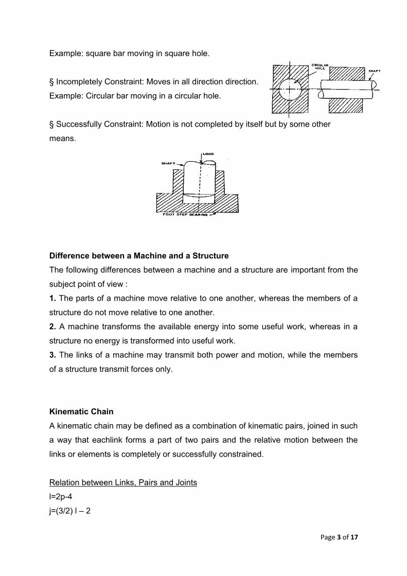
Example: square bar moving in square hole.
§ Incompletely Constraint: Moves in all direction direction.
Example: Circular bar moving in a circular hole.
§ Successfully Constraint: Motion is not completed by itself but by some other
means.
Difference between a Machine and a StructureThe following differences between a machine and a structure are important from the
subject point of view :
1. The parts of a machine move relative to one another, whereas the members of a
structure do not move relative to one another.
2. A machine transforms the available energy into some useful work, whereas in a
structure no energy is transformed into useful work.
3. The links of a machine may transmit both power and motion, while the members
of a structure transmit forces only.
Kinematic ChainA kinematic chain may be defined as a combination of kinematic pairs, joined in such
a way that eachlink forms a part of two pairs and the relative motion between the
links or elements is completely or successfully constrained.
Relation between Links, Pairs and Joints
l=2p-4
j=(3/2) l – 2

Page 4 of 17
l => No of Links
p => No of Pairs
j => No of Joints
L.H.S > R.H.S => Locked chain
L.H.S = R.H.S => Constrained Kinematic Chain
L.H.S < R.H.S => Unconstrained Kinematic Chain
l = 3;, p = 3;j = 3
l = 2p – 4
3 = 2 × 3 – 4 = 2
i.e. L.H.S. > R.H.S.
j=(3/2) l – 2
3=(3/2)3 – 2 = 2.5
i.e. L.H.S. > R.H.S.
ABC does not form a Kinematic chain but forms a structure.
Types of Joints:(a) Binary Joint: If two links are connected at the same end it is called as binary
joint.
(b) A.W Klein:J + h/2 = 3/2 n - 2
J - Joints (B); h - higher pairs; n - links
(c) Ternary joint. When three links are joined at the same connection, the joint is
known as ternary joint. It is equivalent to two binary joints as one of the three links
joined carry the pin for the other two links.

Page 5 of 17
(d)Quaternary joint. When four links are joined at the same connection, the joint is
called a quaternary joint. It is equivalent to three binary joints. In general, when l
number of links are joined at the same connection, the joint is equivalent to (l – 1)
binary joints.
MechanismWhen one of the links of a kinematic chain is fixed, the chain is known as
mechanism. It may be used for transmitting or transforming motion. Example:
engine, indicator, type writer.
Difference between Machine and Mechanism:

Page 6 of 17
Degree of Freedom for plane Mechanism m (mobility):It is defined as the no of input motions, which must be independently controlled in
order to bring mechanism into useful engineering purpose.
Kutzbach eriterion:In a mechanism, one of the links is to be fixed, therefore the number of movable links
will be (l – 1) and thus the total number of degrees of freedom will be 3 (l – 1) before
they are connected to any other link. In general l number of links is connected by
number of binary joints (or) lower pairs and h number of higher pairs, then the
number of degrees of freedom of a mechanism is n = 3 ( l - 1 ) - 2j-h.
n = 3 (l - 1) - 2j - h (Kutzbach criterion)
Grubler's criterion for plane motion:n = 3 (l - 1) - 2 j - h
When h = 0, n = 1
We get a constrained motion given by
3 l - 2 j - 4 = 0
Grashof's Law:
The sum of the longest and the shortest length should not be greater than the
sum of remaining two links length if there is to be continuous relative motion
between the two links.
Page 7 of 17
In a four-bar linkage, we refer to the line segment between hinges on a given
link as a bar where:
· s = length of shortest bar
· l = length of longest bar
· p, q = lengths of intermediate bar
Grashof's theorem states that a four-bar mechanism has at least one revolving link
if
s + l <= p + q (1) and all three mobile links will rock if
s + l > p + q (2)
The inequality 1 is Grashof's criterion.
The link opposite the frame is called the coupler link, and the links which are
hinged to the frame are called side links.
A link which is free to rotate through 360 degree with respect to a second link
will be said to revolve relative to the second link (not necessarily a frame).
If it is possible for all four bars to become simultaneously aligned, such a state
is called a change point.
Some important concepts in link mechanisms are:
Crank: A side link which revolves relative to the frame is called a crank.
Rocker: Any link which does not revolve is called a rocker.
Crank-rocker mechanism: In a four bar linkage, if the shorter side link revolves and
the other one rocks (i.e., oscillates), it is called a crank-rocker mechanism.
Double-crank mechanism: In a four bar linkage, if both of the side links revolve, it is
called a double-crank mechanism.
Double-rocker mechanism: In a four bar linkage, if both of the side links rock, it is
called a double-rocker mechanism
Kinematic Inversions of Mechanisms:This method of obtaining different mechanisms by fixing different links in a Kinematic
chain, it is known as inversion mechanism.
Types of Kinematic Chain:

Page 8 of 17
and two sliding pair)
Inversions of Four Bar ChainFour Bar Chain (Or) Quadratic Cycle ChainIt consists of four links, each of them forms a turning pair at A, B, C and D. The four
links may be of different lengths. Rotating link is known as crank or driver. AD (link
4) is a crank. The link BC (link 2) which makes a partial rotation or oscillates is
known as lever or rocker or follower and the link CD (link 3) which connects the
crank and lever is called connecting rod or coupler. The fixed link AB (link 1) is
known as frame of the mechanism. When the crank (link 4) is the driver, the
mechanism is transforming rotary motion into oscillating motion.
Beam Engine: (Crank and LeverMechanism)
In this mechanism, when the crank rotates about
the fixed centre A, the lever oscillates about a
fixed centre D. The end E of the lever CDE is
connected to a piston rod which reciprocates due
to the rotation of the crank. In other words, the
purpose of this mechanism is to convert rotary
motion into reciprocating motion.
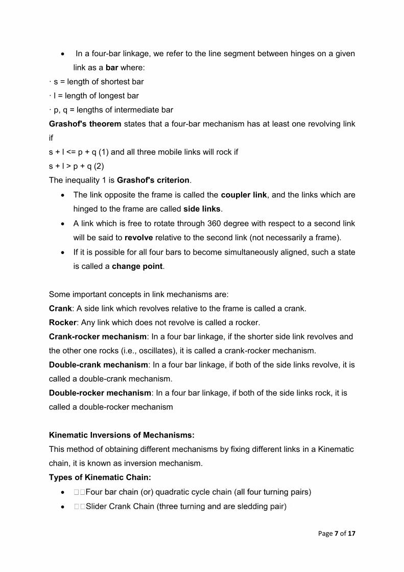
Coupling rod of a locomotive (Double Crank mechanism).The mechanism of a coupling rod of a locomotive which consists of 4 links is shown
in Figure. In this mechanism, the links AD and BC (having equal length) act as crank
and are connected to the respective wheels. The links CD act as coupling rod and
link AB is fixed in order to maintain constant center to center distance between
them. This mechanism is meant for transmitting rotary motion from one wheel
together wheel.
Page 9 of 17
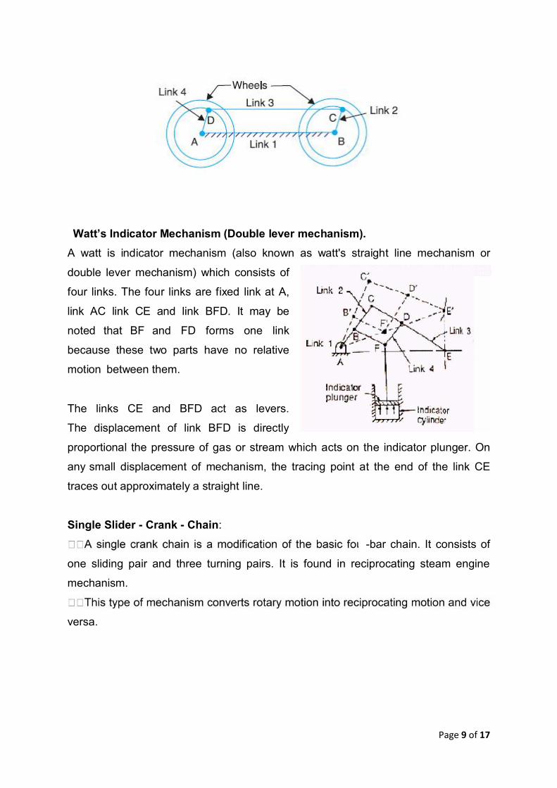
Watt’s Indicator Mechanism (Double lever mechanism).A watt is indicator mechanism (also known as watt's straight line mechanism or
double lever mechanism) which consists of
four links. The four links are fixed link at A,
link AC link CE and link BFD. It may be
noted that BF and FD forms one link
because these two parts have no relative
motion between them.
The links CE and BFD act as levers.
The displacement of link BFD is directly
proportional the pressure of gas or stream which acts on the indicator plunger. On
any small displacement of mechanism, the tracing point at the end of the link CE
traces out approximately a straight line.
Single Slider - Crank - Chain:
-bar chain. It consists of
one sliding pair and three turning pairs. It is found in reciprocating steam engine
mechanism.
versa.
Page 10 of 17
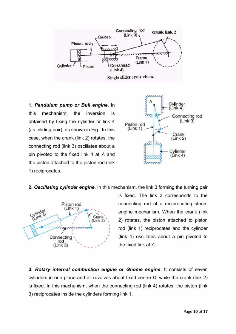
1. Pendulum pump or Bull engine. In
this mechanism, the inversion is
obtained by fixing the cylinder or link 4
(i.e. sliding pair), as shown in Fig. In this
case, when the crank (link 2) rotates, the
connecting rod (link 3) oscillates about a
pin pivoted to the fixed link 4 at A and
the piston attached to the piston rod (link
1) reciprocates.
2. Oscillating cylinder engine. In this mechanism, the link 3 forming the turning pair
is fixed. The link 3 corresponds to the
connecting rod of a reciprocating steam
engine mechanism. When the crank (link
2) rotates, the piston attached to piston
rod (link 1) reciprocates and the cylinder
(link 4) oscillates about a pin pivoted to
the fixed link at A.
3. Rotary internal combustion engine or Gnome engine. It consists of seven
cylinders in one plane and all revolves about fixed centre D, while the crank (link 2)
is fixed. In this mechanism, when the connecting rod (link 4) rotates, the piston (link
3) reciprocates inside the cylinders forming link 1.

Page 11 of 17
4. Crank and slotted lever quick return motion mechanism. In this mechanism,
the link AC (i.e. link 3) forming the
turning pair is fixed. The link 3
corresponds to the connecting rod
of a reciprocating steam engine.
The driving crank CB revolves with
uniform angular speed about the
fixed centre C. A sliding block
attached to the crank pin at B slides
along the slotted bar AP and thus
causes AP to oscillate about the
pivoted point A. A short link PR
transmits the motion from AP to the
ram which carries the tool and reciprocates along the line of stroke R1R2. The line of
stroke of the ram (i.e. R1R2) is perpendicular to AC produced.
In the extreme positions, AP1 and AP2 are tangential to the circle and the cutting
tool is at the end of the stroke. The forward or cutting stroke occurs when the crank
rotates from the position CB1 to CB2 (or through an angle ) in the clockwise
direction. The return stroke occurs when the crank rotates from the position CB2 to
CB1 (or through angle α in the clockwise direction.

Page 12 of 17
Whitworth quick return motion mechanism. This mechanism is mostly used in
shaping and slotting machines. In this mechanism, the link CD (link 2) forming the
turning pair is fixed, as shown in Fig. 5.27. The link 2 corresponds to a crank in a
reciprocating steam engine. The driving crank CA (link 3) rotates at a uniform
angular speed. The slider (link 4) attached to the crank pin at A slides along the
slotted bar PA (link 1) which oscillates at a pivoted point D. The connecting rod PR
carries the ram at R to which a cutting tool is fixed. The motion of the tool is
constrained along the line RD produced, i.e. along a line passing through D and
perpendicular to CD.
Page 13 of 17
When the driving crank CA moves from the position CA1 to CA2 (or the link DP from
the position DP1 to DP2) through an angle α in the clockwise direction, the tool
moves from the left hand end of its stroke to the right hand end through a distance 2
PD. Now when the driving crank moves from the position CA2 to CA1 (or the link DP
from DP2 to DP1 ) through an angle β in the clockwise direction, the tool moves back
from right hand end of its stroke to the left hand end.
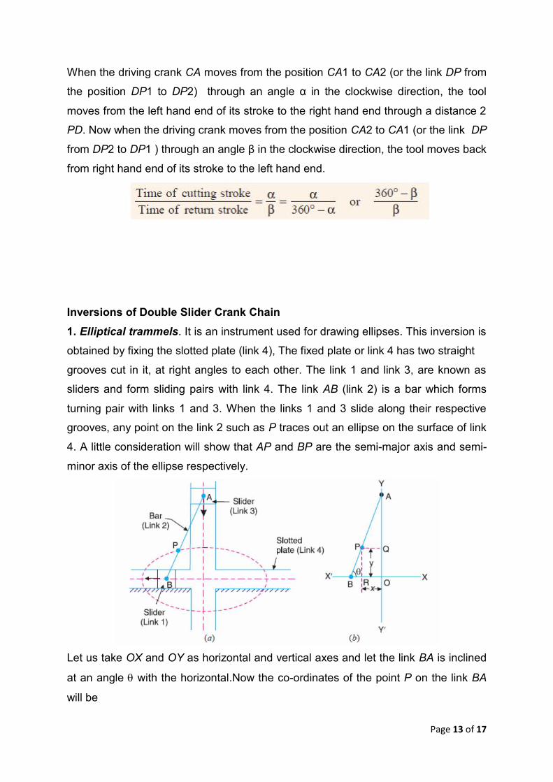
Inversions of Double Slider Crank Chain1. Elliptical trammels. It is an instrument used for drawing ellipses. This inversion is
obtained by fixing the slotted plate (link 4), The fixed plate or link 4 has two straight
grooves cut in it, at right angles to each other. The link 1 and link 3, are known as
sliders and form sliding pairs with link 4. The link AB (link 2) is a bar which forms
turning pair with links 1 and 3. When the links 1 and 3 slide along their respective
grooves, any point on the link 2 such as P traces out an ellipse on the surface of link
4. A little consideration will show that AP and BP are the semi-major axis and semi-
minor axis of the ellipse respectively.
Let us take OX and OY as horizontal and vertical axes and let the link BA is inclined
at an angle with the horizontal.Now the co-ordinates of the point P on the link BA
will be

Page 14 of 17
This is the equation of an ellipse. Hence the path traced by point P is an ellipse
whose semimajor axis is AP and semi-minor axis is BP.
Scotch yoke mechanism. This
mechanism is used for converting rotary
motion into a reciprocating motion. The
inversion is obtained by fixing either the
link 1 or link 3. In Fig., link 1 is fixed. In this
mechanism, when the link 2 (which
corresponds to crank) rotates about B as
centre, the link 4 (which corresponds to a frame) reciprocates. The fixed link 1
guides the frame.
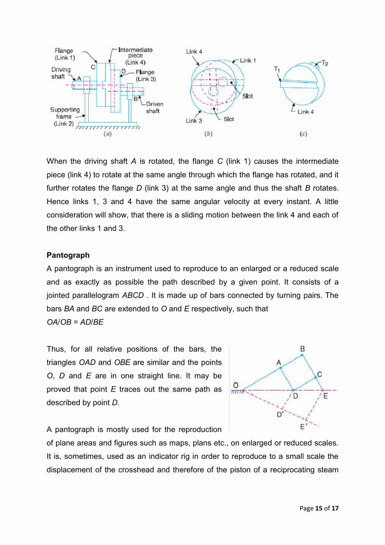
Oldham’s coupling. An oldham's coupling is used for connecting two parallel shafts
whose axes are at a small distance apart. The shafts are coupled in such a way that
if one shaft rotates, the other shaft also rotates at the same speed.
The link 1 and link 3 form turning pairs with link 2. These flanges have diametrical
slots cut in their inner faces. The intermediate piece (link 4) which is a circular disc,
have two tongues (i.e. diametrical projections) T1 and T2 on each face at right
angles to each other. The tongues on the link 4 closely fit into the slots in the two
flanges (link 1 and link 3). The link 4 can slide or reciprocate in the slots in the
flanges.
Page 15 of 17
When the driving shaft A is rotated, the flange C (link 1) causes the intermediate
piece (link 4) to rotate at the same angle through which the flange has rotated, and it
further rotates the flange D (link 3) at the same angle and thus the shaft B rotates.
Hence links 1, 3 and 4 have the same angular velocity at every instant. A little
consideration will show, that there is a sliding motion between the link 4 and each of
the other links 1 and 3.
PantographA pantograph is an instrument used to reproduce to an enlarged or a reduced scale
and as exactly as possible the path described by a given point. It consists of a
jointed parallelogram ABCD . It is made up of bars connected by turning pairs. The
bars BA and BC are extended to O and E respectively, such that
OA/OB = AD/BE
Thus, for all relative positions of the bars, the
triangles OAD and OBE are similar and the points
O, D and E are in one straight line. It may be
proved that point E traces out the same path as
described by point D.
A pantograph is mostly used for the reproduction
of plane areas and figures such as maps, plans etc., on enlarged or reduced scales.
It is, sometimes, used as an indicator rig in order to reproduce to a small scale the
displacement of the crosshead and therefore of the piston of a reciprocating steam

Page 16 of 17
engine. It is also used to guide cutting tools. A modified form of pantograph is used
to collect power at the top of an electric locomotive.
Peaucellier mechanism. It consists of a fixed link OO1 and the other straight links
O1A, OC, OD, AD, DB, BC and CA are connected by turning pairs at their
intersections. The pin at A is constrained to move along the circumference of a circle
with the fixed diameter OP, by means of the link O1A.
AC = CB = BD = DA ; OC = OD ; and OO1 = O1A
It may be proved that the product OA × OB remains constant, when the link O1A
rotates. Join CD to bisect AB at R. Now from right angled triangles ORC and BRC,
Since OC and BC are of constant length, therefore the product OB × OA remains
constant. Hence the point B traces a straight path perpendicular to the diameter OP.
Watt’s mechanism. The approximate straight line motion mechanisms are the
modifications of the four-bar chain mechanisms. Following mechanisms to give
approximate straight line motion. It is a crossed four bar chain mechanism and was
used by Watt for his early steam engines to guide the piston rod in a cylinder to have
an approximate straight line motion.

Page 17 of 17
1. Explain the term kinematic link. Give the classification of kinematic link.
2. What is a machine ? Giving example, differentiate between a machine and a
structure.
3. Write notes on complete and incomplete constraints in lower and higher pairs,
illustrating your answer with neat sketches.
4. Explain Grubler’s criterion for determining degree of freedom for mechanisms.
5. Explain the terms : 1. Lower pair, 2. Higher pair, 3. Kinematic chain, and 4.
Inversion.
6. In what way a mechanism differ from a machine ?
7. What is the significance of degrees of freedom of a kinematic chain when it
functions as a mechanism?
8. Explain different kinds of kinematic pairs giving example for each one of them.
9. Sketch and explain the various inversions of a four bar chain mechanism?
10.Sketch and explain the various inversions of a slider crank chain
11.Sketch and describe the working of two different types of quick return
mechanisms. Give examples of their applications. Derive an expression for
the ratio of times taken in forward and return stroke for one of these
mechanisms.
12.Sketch and explain any two inversions of a double slider crank chain.
13. In a crank and slotted lever quick return motion mechanism, the distance
between the fixed centres is 240 mm and the length of the driving crank is 120
mm. Find the inclination of the slotted bar with the vertical in the extreme
position and the time ratio of cutting stroke to the return stroke. If the length of
the slotted bar is 450 mm, find the length of the stroke if the line of stroke
passes through the extreme positions of the free end of the lever.