unit-1 - intranet.abes.ac.inintranet.abes.ac.in/department/ece/pdf/classnotes/eec-021.pdf · and...
TRANSCRIPT
UNIT-1
Introduction to Satellite Communications
Satellite Communication combines the missile
and microwave technologies
The space era started in 1957 with the
launching of the first artificial satellite
(sputnik)

Satellite Communications
• Satellite-based antenna(e) in stable orbit above earth.
• Two or more (earth) stations communicate via one or more satellites serving as relay(s) in space.
• Uplink: earth->satellite.
• Downlink: satellite->earth.
• Transponder: satellite electronics converting uplink signal to downlink.

Satellite Communications
• Satellite Transponder is a microwave device consisting of receiver, repeater and regenerator in orbit
• Satellite transmission involves sending signals to satellite that receive, amplify, and transmit back to earth

Capabilities of Satellite Transmission
• Point-to-point transmission
– To transfer large volume of data
– Voice, data, etc communication
– Video conference
• Point-to-multipoint transmission
– Data communication
– Internet
– Video conference
• Broadcast services such as television

Satellite Network Configurations
Advantages of Satellite Communication
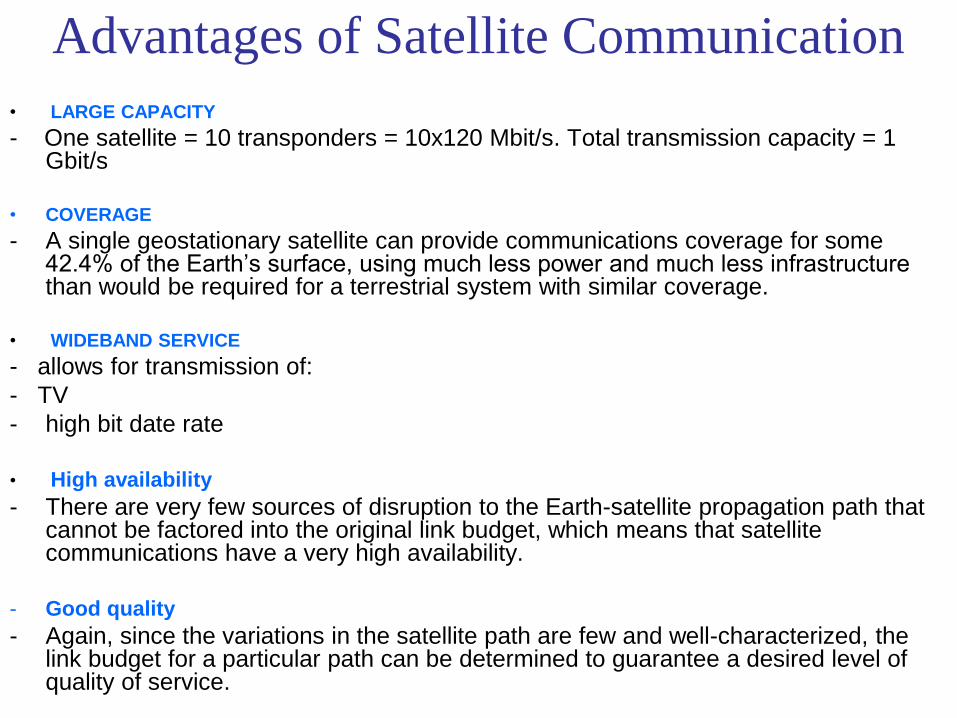
• LARGE CAPACITY
- One satellite = 10 transponders = 10x120 Mbit/s. Total transmission capacity = 1 Gbit/s
• COVERAGE
- A single geostationary satellite can provide communications coverage for some 42.4% of the Earth’s surface, using much less power and much less infrastructure than would be required for a terrestrial system with similar coverage.
• WIDEBAND SERVICE
- allows for transmission of:
- TV
- high bit date rate
• High availability
- There are very few sources of disruption to the Earth-satellite propagation path that cannot be factored into the original link budget, which means that satellite communications have a very high availability.
- Good quality
- Again, since the variations in the satellite path are few and well-characterized, the link budget for a particular path can be determined to guarantee a desired level of quality of service.

History of satellite communication
• 1945 Arthur C. Clarke publishes an essay about „Extra
Terrestrial Relays“
• 1957 first satellite SPUTNIK
• 1960 first reflecting communication satellite ECHO
• 1963 first geostationary satellite SYNCOM
• 1965 first commercial geostationary satellite Satellit „Early Bird“
(INTELSAT I): 240 duplex telephone channels or 1 TV
channel, 1.5 years lifetime
• 1976 three MARISAT satellites for maritime communication
• 1982 first mobile satellite telephone system INMARSAT-A
• 1988 first satellite system for mobile phones and data
communication INMARSAT-C
• 1993 first digital satellite telephone system
• 1998 global satellite systems for small mobile phones

Sputnik 1
• Launched October 14, 1957 – from the Baikonur
Cosmodrome in Kazakhstan
• 184 pounds
• Orbital period 90 minutes
• Broadcast “beep beep” – 20 and 40 MHz
• Shocked the US into action – Started space race

Now: Boeing 702 DBS Satellite
• 134.5 feet long
• 2645 lbs payload
• 11,464 lbs takeoff weight
• Over 100 high-power transponders (94 active/24 spare)
• Up to 25 kW power
• Xenon-Ion Propulsion System
• Built for direct broadcast and point to point services.

Intercontinental telephone,
data, and video relay
• Initially satellite links were only:
– One-way video and data traffic
– Backup to undersea telephone cables
• Because:
– Nominal 1-2 second time delay for a round-trip voice message.

VSAT - Private Networks
• VSAT – Very Small Aperture
Terminal
• Replaces wireline data connections to businesses – Convenience stores,
malls, restaurants, gas stations
• Common uses – Muzak background music
– Credit card transactions
– Corporate communications
• 64kbps to 2Mbps

Mobile Satellite Services
• Inmarsat - communications to ships at sea.
• Expanded – Aircraft
– Trucks
– Rail locomotives.
– Suitcase sized terminals • Used extensively in disaster situations and remote
exploration.
• Not suitable for handheld equipment – Antennas and terminals required
• Analog and digital services are used.

In the Future ?
Internet backbone services
• Teledesic
– Internet in the sky
– 120 Mb uplink
– 720 Mb downlink.
– Ka band
• LEO constellation
– Inter-satellite links
– Scalable
• Viability in question
– Iridium debacle
• System scaled back
– From 240 satellites
– To only 30 satellites
– Nothing launched yet
Major Organisations
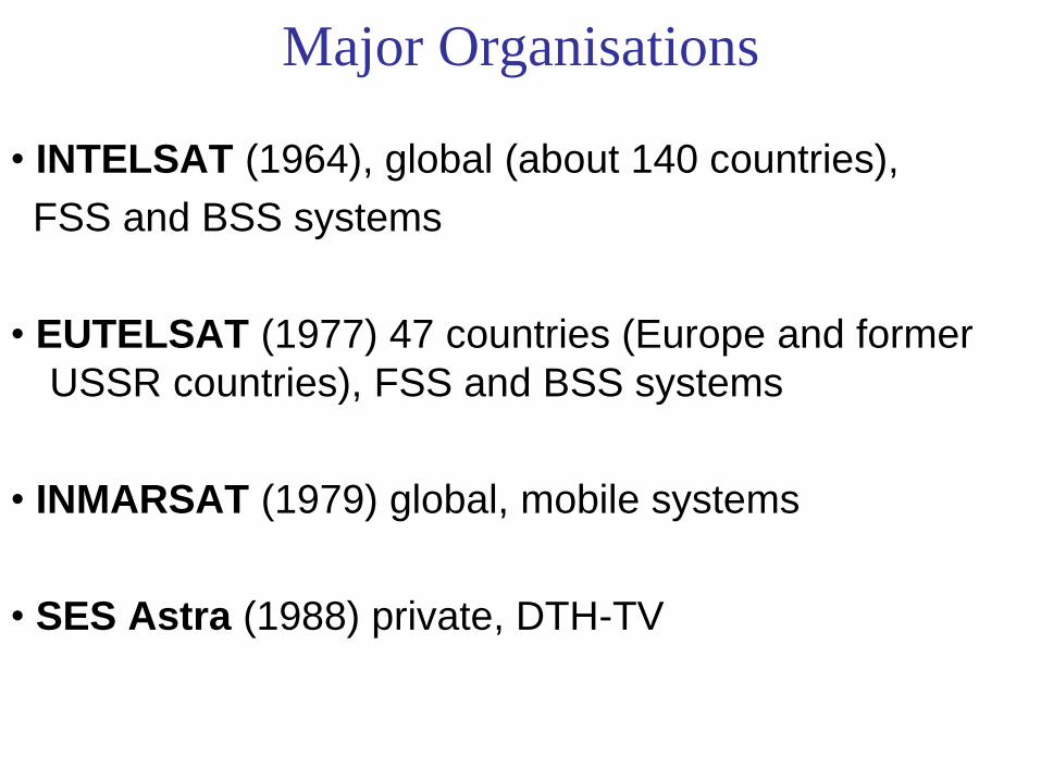
• INTELSAT (1964), global (about 140 countries),
FSS and BSS systems
• EUTELSAT (1977) 47 countries (Europe and former
USSR countries), FSS and BSS systems
• INMARSAT (1979) global, mobile systems
• SES Astra (1988) private, DTH-TV
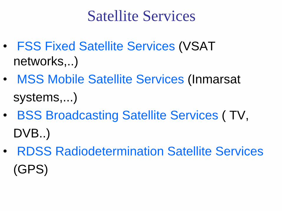
Satellite Services
• FSS Fixed Satellite Services (VSAT
networks,..)
• MSS Mobile Satellite Services (Inmarsat
systems,...)
• BSS Broadcasting Satellite Services ( TV,
DVB..)
• RDSS Radiodetermination Satellite Services
(GPS)
Satellite Orbits

Satellite Orbits GEO
advantages:
- the satellite appears to be fixed (immovable) when viewed from the Earth, no tracking required for earth station antennas
- about. 40% of the earth`s surface is in view from the satellite
disadvantages:
- high attenuation level (power loss) (200dB) on the path
- large signal delay (238-284ms)
- polar regions (latitudes > 81 deg.) are not covered
LEO
advantages:
- much smaller attenuation compare GEO satellites
- low signal delay
disadvantages:
- short period satellite visibility (through earth station), many times during the day
- Doppler effect
- many satellites are required for establishing continuous transmission

Satellite period and orbits
10 20 30 40 x106 m
24
20
16
12
8
4
radius
satellite
period [h] velocity [ x1000 km/h]
synchronous distance
35,786 km

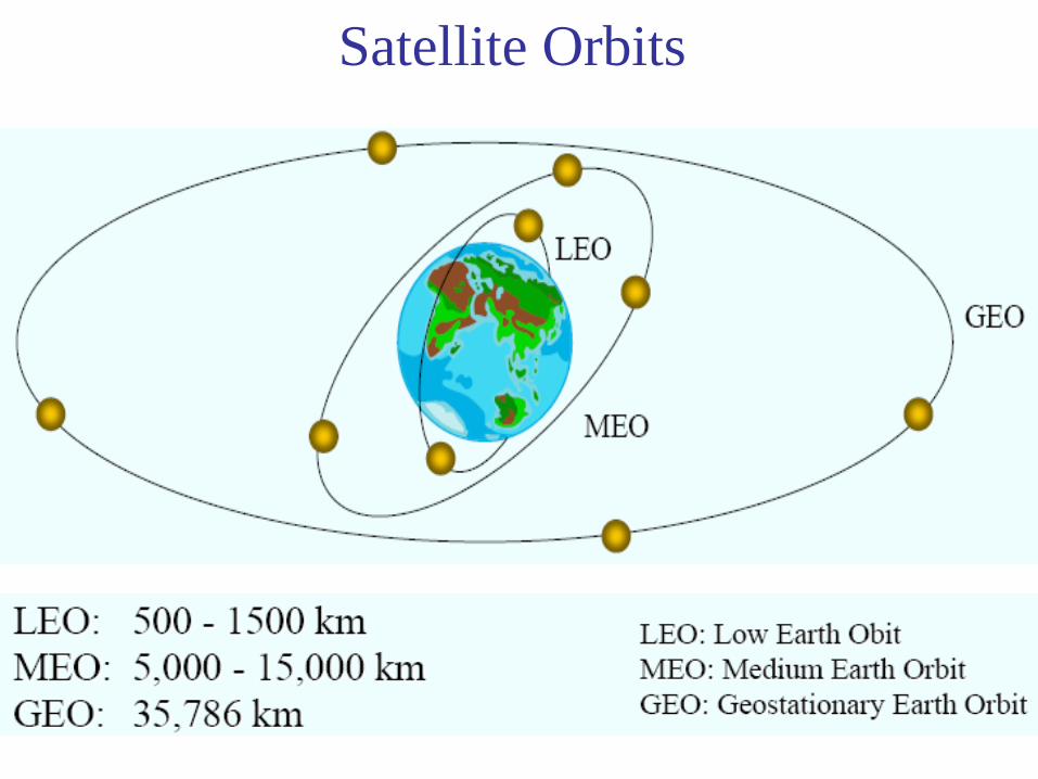
• Four different types of satellite orbits can be identified
depending on the shape and diameter of the orbit:
• GEO: geostationary orbit, ca. 36000 km above earth
surface
• LEO (Low Earth Orbit): ca. 500 - 1500 km
• MEO (Medium Earth Orbit) or ICO (Intermediate
Circular Orbit): ca. 6000 - 20000 km
• HEO (Highly Elliptical Orbit) elliptical orbits
Orbits I
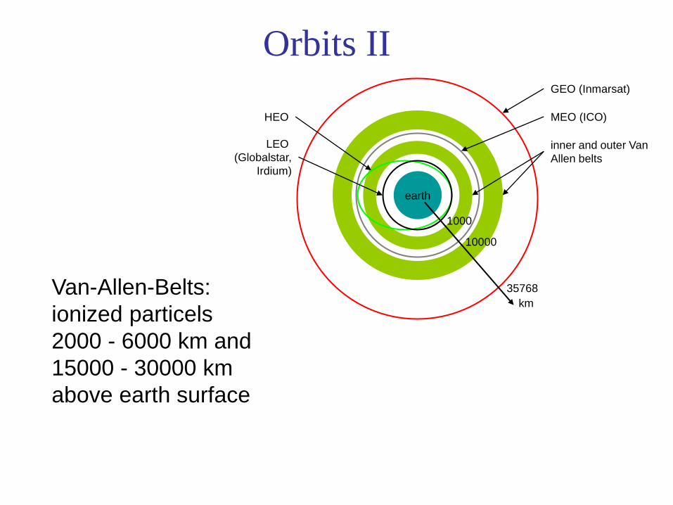
Orbits II
earth
km
35768
10000
1000
LEO
(Globalstar,
Irdium)
HEO
inner and outer Van
Allen belts
MEO (ICO)
GEO (Inmarsat)
Van-Allen-Belts:
ionized particels
2000 - 6000 km and
15000 - 30000 km
above earth surface

Space Weather
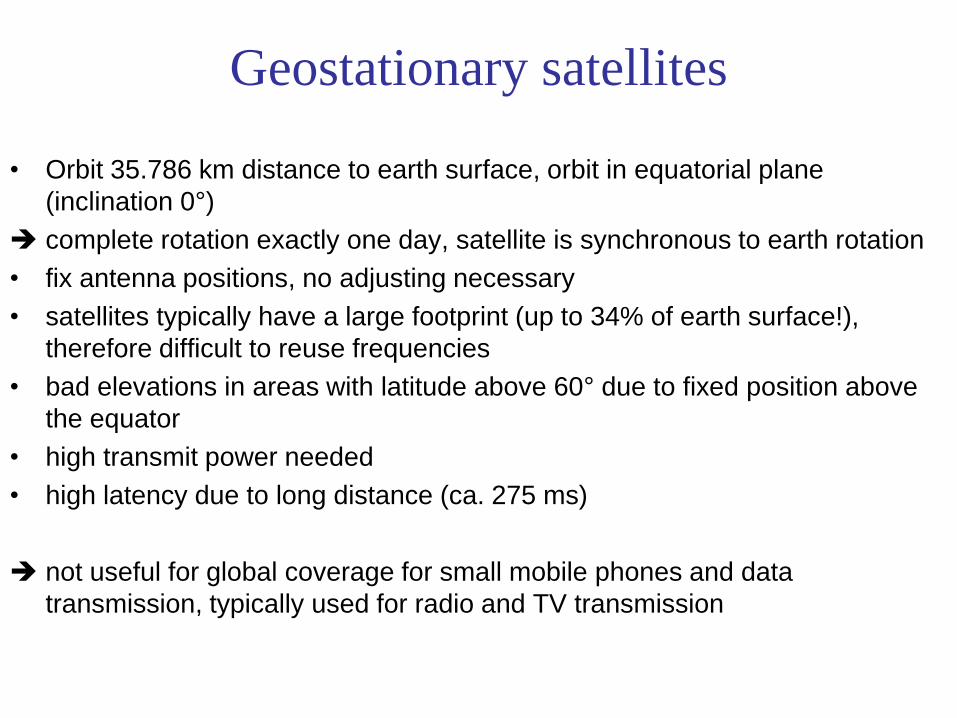
Geostationary satellites
• Orbit 35.786 km distance to earth surface, orbit in equatorial plane
(inclination 0°)
complete rotation exactly one day, satellite is synchronous to earth rotation
• fix antenna positions, no adjusting necessary
• satellites typically have a large footprint (up to 34% of earth surface!),
therefore difficult to reuse frequencies
• bad elevations in areas with latitude above 60° due to fixed position above
the equator
• high transmit power needed
• high latency due to long distance (ca. 275 ms)
not useful for global coverage for small mobile phones and data
transmission, typically used for radio and TV transmission

LEO systems
• Orbit ca. 500 - 1500 km above earth surface
• visibility of a satellite ca. 10 - 40 minutes
• global radio coverage possible
• latency comparable with terrestrial long distance connections, ca. 5 - 10
ms
• smaller footprints, better frequency reuse
• but now handover necessary from one satellite to another
• many satellites necessary for global coverage
• more complex systems due to moving satellites
• Examples:
• Iridium (start 1998, 66 satellites)
• Globalstar (start 1999, 48 satellites)

MEO systems
• Orbit ca. 5000 - 12000 km above earth surface
• comparison with LEO systems:
• slower moving satellites
• less satellites needed
• simpler system design
• for many connections no hand-over needed
• higher latency, ca. 70 - 80 ms
• higher sending power needed
• special antennas for small footprints needed
• Example:
• ICO (Intermediate Circular Orbit, Inmarsat) start ca. 2000
GEO vs LEO
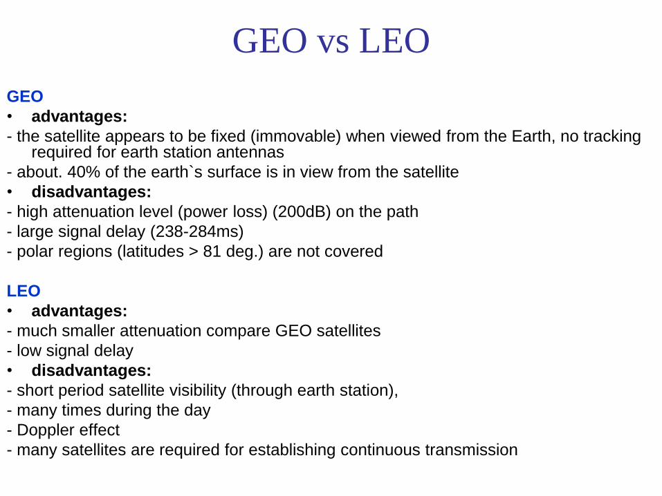
GEO
• advantages:
- the satellite appears to be fixed (immovable) when viewed from the Earth, no tracking required for earth station antennas
- about. 40% of the earth`s surface is in view from the satellite
• disadvantages:
- high attenuation level (power loss) (200dB) on the path
- large signal delay (238-284ms)
- polar regions (latitudes > 81 deg.) are not covered
LEO
• advantages:
- much smaller attenuation compare GEO satellites
- low signal delay
• disadvantages:
- short period satellite visibility (through earth station),
- many times during the day
- Doppler effect
- many satellites are required for establishing continuous transmission

Communication Satellites

Overview of LEO/MEO systems
Iridium Globalstar ICO Teledesic
# satellites 66 + 6 48 + 4 10 + 2 288
altitude(km)
780 1414 10390 ca. 700
coverage global 70° latitude global global
min.elevation
8° 20° 20° 40°
frequencies[GHz(circa)]
1.6 MS29.2
19.5
23.3 ISL
1.6 MS
2.5 MS
5.1
6.9
2 MS
2.2 MS
5.2
7
19
28.8
62 ISL
accessmethod
FDMA/TDMA CDMA FDMA/TDMA FDMA/TDMA
ISL yes no no yes
bit rate 2.4 kbit/s 9.6 kbit/s 4.8 kbit/s 64 Mbit/s
2/64 Mbit/s
# channels 4000 2700 4500 2500
Lifetime[years]
5-8 7.5 12 10
costestimation
4.4 B$ 2.9 B$ 4.5 B$ 9 B$
Spectrum Allocation
Frequency Spectrum concepts:
• Frequency: Rate at which an electromagnetic wave reverts its polarity (oscillates) in cycles per second or Hertz (Hz).
• Wavelength: distance between wavefronts in space. Given in meters as:
λ = c/f
Where: c = speed of light (3x10⁸ m/s in vacuum) f = frequency in Hertz
• Frequency band: range of frequencies.
• Bandwidth: Size or “width” (in Hertz) or a frequency band.
• Electromagnetic Spectrum: full extent of all frequencies from zero to infinity.

Radio Frequencies (RF)
• RF Frequencies: Part of the electromagnetic spectrum
ranging between 300 MHz and 300 GHz. Interesting properties:
– Efficient generation of signal power
– Radiates into free space
– Efficient reception at a different point.
Differences depending on the RF frequency used:
- Signal Bandwidth
- Propagation effects (diffraction, noise, fading)
- Antenna Sizes
Microwave Frequencies
• Sub-range of the RF frequencies approximately from
1GHz to 30GHz. Main properties:
- Line of sight propagation (space and atmosphere).
- Blockage by dense media (hills, buildings, rain)
- Wide bandwidths compared to lower frequency bands.
- Compact antennas, directionality possible.
- Reduced efficiency of power amplification as frequency grows:
Radio Frequency Power OUT
Direct Current Power IN

Radio Frequency Spectrum
Commonly Used Bands

Frequency Bands
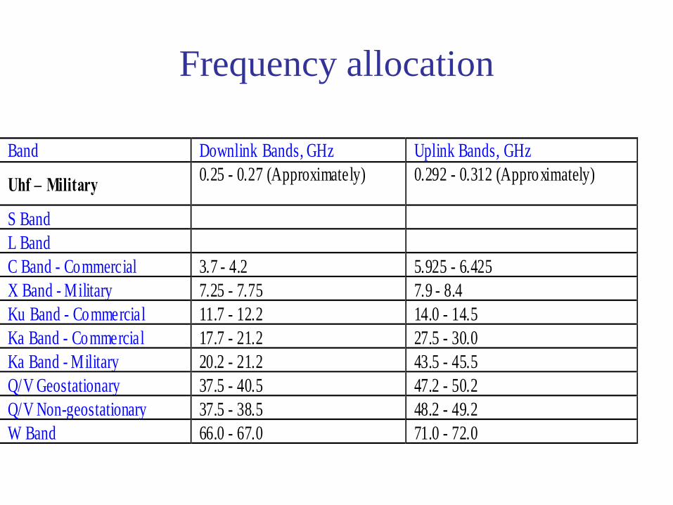
Frequency allocation
Band Downlink Bands, GHz Uplink Bands, GHz
Uhf – Military0.25 - 0.27 (Approximately) 0.292 - 0.312 (Approximately)
S Band
L Band
C Band - Commercial 3.7 - 4.2 5.925 - 6.425
X Band - Military 7.25 - 7.75 7.9 - 8.4
Ku Band - Commercial 11.7 - 12.2 14.0 - 14.5
Ka Band - Commercial 17.7 - 21.2 27.5 - 30.0
Ka Band - Military 20.2 - 21.2 43.5 - 45.5
Q/V Geostationary 37.5 - 40.5 47.2 - 50.2
Q/V Non-geostationary 37.5 - 38.5 48.2 - 49.2
W Band 66.0 - 67.0 71.0 - 72.0
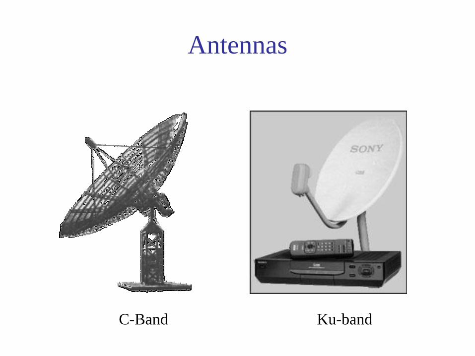
C-Band Ku-band
Antennas

Insights on Frequency Selection: (Part 1: Lower frequencies, stronger links)
• LEO satellites need lower RF frequencies:
– Omni-directional antennas on handsets have low gain - typically
G = 0 db = 1
– Flux density F in W/m2 at the earth’s surface in any beam is
independent of frequency
– Received power is F x A watts , where A is effective area of
antenna in square meters
– For an omni-directional antenna A = G λ2/ 4 π = λ2/ 4 π
– At 450 MHz, A = 353 cm2, at 20 GHz, A = 0.18 cm2
– Difference is 33 dB - so don’t use 20 GHz with an omni!

Insights on Frequency Selection: (Part 2: Higher frequencies, higher capacity)
• GEO satellites need more RF frequencies
– High speed data links on GEO satellites need about 0.8 Hz of RF bandwidth per bit/sec.
– A 155 Mbps data link requires 125 MHz bandwidth
– Available RF bandwidth:
C band 500 MHz (All GEO slots occupied)
Ku band 750 MHz (Most GEO slots occupied)
Ka band 2000 MHz (proliferating)
Q/V band ?

Satellite Link Performance Factors
• Distance between earth station antenna and satellite
antenna
• For downlink, terrestrial distance between earth
station antenna and “aim point” of satellite
– Displayed as a satellite footprint
• Atmospheric attenuation
– Affected by oxygen, water, angle of elevation, and higher
frequencies

Elevation
Elevation:
angle between center of satellite beam
and surface
minimal elevation:
elevation needed at least
to communicate with the satellite

Atmospheric attenuation Example: satellite systems at 4-6 GHz
elevation of the satellite
5° 10° 20° 30° 40° 50°
Attenuation of
the signal in %
10
20
30
40
50
rain absorption
fog absorption
atmospheric
absorption
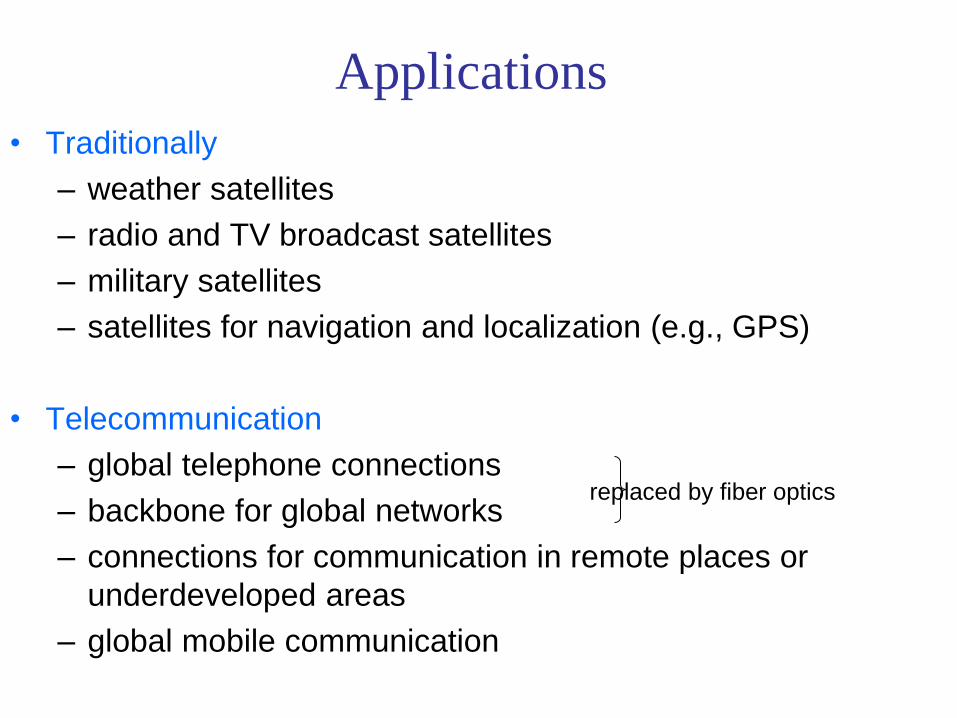
Applications
• Traditionally
– weather satellites
– radio and TV broadcast satellites
– military satellites
– satellites for navigation and localization (e.g., GPS)
• Telecommunication
– global telephone connections
– backbone for global networks
– connections for communication in remote places or
underdeveloped areas
– global mobile communication
replaced by fiber optics

Initial application of GEO Satellites:
Telephony
• 1965 Early Bird 34 kg 240 telephone ccts.
• 1968 Intelsat III 152 kg 1 500 circuits
• 1986 Intelsat VI 1,800 kg 33,000 circuits
• 2000 Large GEO 3000 kg 8 - 15 kW power
1,200 kg payload

Current GEO Satellite Applications:
• Broadcasting - mainly TV at present
– DirecTV, PrimeStar, etc.
• Point to Multi-point communications
– VSAT, Video distribution for Cable TV
• Mobile Services
– Motient (former American Mobile Satellite),
INMARSAT, etc.

Satellite Navigation:
GPS and GLONASS
• GPS is a medium earth orbit (MEO) satellite system
– GPS satellites broadcast pulse trains with very accurate time signals
– A receiver able to “see” four GPS satellites can calculate its position within 30 m anywhere in world
– 24 satellites in clusters of four, 12 hour orbital period
• “You never need be lost again”
– Every automobile and cellular phone will eventually have a GPS location read-out
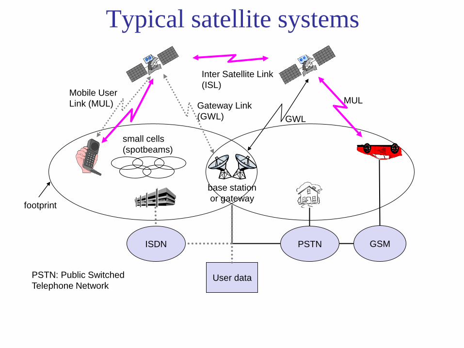
base station
or gateway
Typical satellite systems
Inter Satellite Link
(ISL) Mobile User
Link (MUL) Gateway Link
(GWL)
footprint
small cells
(spotbeams)
User data
PSTN ISDN GSM
GWL
MUL
PSTN: Public Switched
Telephone Network
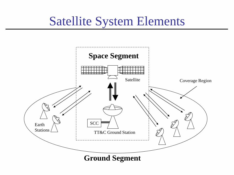
Space Segment
Satellite
TT&C Ground Station
Satellite System Elements
Ground Segment
Earth
Stations
Coverage Region
SCC
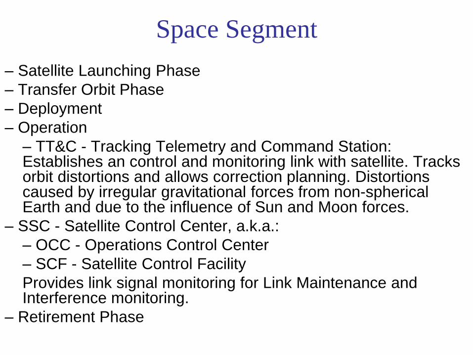
Space Segment
– Satellite Launching Phase
– Transfer Orbit Phase
– Deployment
– Operation
– TT&C - Tracking Telemetry and Command Station: Establishes an control and monitoring link with satellite. Tracks orbit distortions and allows correction planning. Distortions caused by irregular gravitational forces from non-spherical Earth and due to the influence of Sun and Moon forces.
– SSC - Satellite Control Center, a.k.a.:
– OCC - Operations Control Center
– SCF - Satellite Control Facility
Provides link signal monitoring for Link Maintenance and Interference monitoring.
– Retirement Phase

Space segment

Satellite Transponder

Ground Segment
Earth Station = Satellite Communication Station (air, ground or sea, fixed or mobile).
FSS – Fixed Satellite Service MSS – Mobile Satellite Service
Collection of facilities, users and applications.
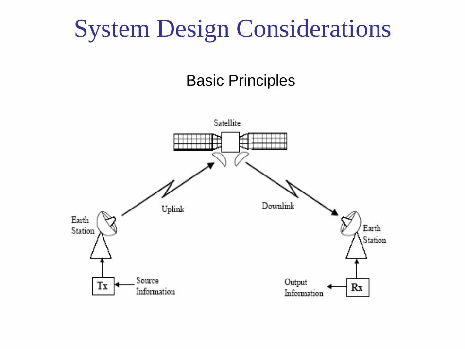
System Design Considerations
Basic Principles

Signals
• Signals:
– Carried by wires as voltage or current
– Transmitted through space as electromagnetic waves.
– Analog: Voltage or Current proportional to signal. E.g. Telephone.
– Digital: Generated by computers.
Ex. Binary = 1 or 0 corresponding to +1V or –1V.
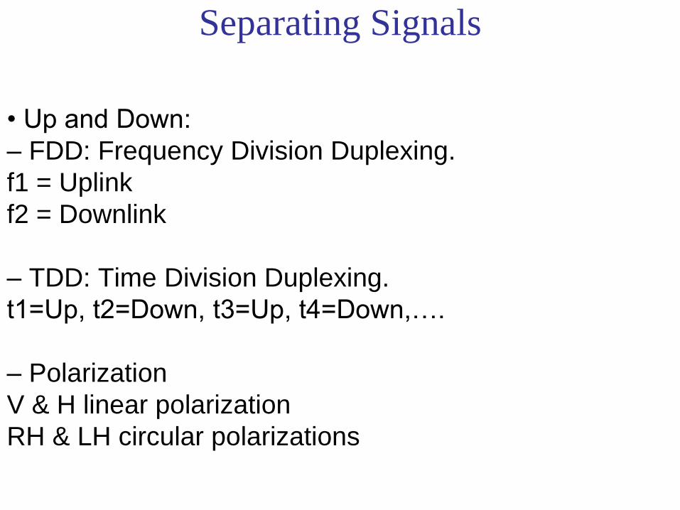
Separating Signals
• Up and Down:
– FDD: Frequency Division Duplexing.
f1 = Uplink
f2 = Downlink
– TDD: Time Division Duplexing.
t1=Up, t2=Down, t3=Up, t4=Down,….
– Polarization
V & H linear polarization
RH & LH circular polarizations

Separating Signals (so that many transmitters can use the same transponder
simultaneously)
• Between Users or “Channels” (Multiple Access):
– FDMA: Frequency Division Multiple Access; assigns
each transmitter its own carrier frequency f1 = User 1; f2 = User 2; f3 = User 3, …
– TDMA: Time Division Multiple Access; each
transmitter is given its own time slot t1=User_1, t2=User_2, t3=User_3, t4 = User_1, ...
– CDMA: Code Division Multiple Access; each
transmitter transmits simultaneously and at the same
frequency and each transmission is modulated by its
own pseudo randomly coded bit stream Code 1 = User 1; Code 2 = User 2; Code 3 = User 3

Digital Communication System

Current Trends in Satellite
Communications
• Bigger, heavier, GEO satellites with multiple roles
• More direct broadcast TV and Radio satellites
• Expansion into Ka, Q, V bands (20/30, 40/50 GHz)
• Massive growth in data services fueled by Internet
• Mobile services:
– May be broadcast services rather than point to point
– Make mobile services a successful business?

The Future for Satellite
Communications
• Growth requires new frequency bands
• Propagation through rain and clouds becomes a problem as RF frequency is increased
– C-band (6/4 GHz) Rain has little impact 99.99% availability is possible
– Ku-band (10-12 GHz) Link margin of 3 dB needed for 99.8% availability
– Ka-band (20 - 30 GHz) Link margin of 6 dB needed for 99.6% availability

The Future for Satellite
Communications
• Low cost phased array antennas for mobiles are needed
– Mobile systems are limited by use of omni-directional antennas
– A self-phasing, self-steering phased array antenna with 6 dB gain can quadruple the capacity of a system
– Directional antennas allow frequency re-use

The Future for Satellite
Communications • Expected revenues from all Satellite
Communications services should reach $75 billion by
2005
• Satellite Direct-to-Home (DTH) Video and Internet
services appear to be the major drivers

Orbital Mechanics
Part 1

Kinematics & Newton’s Law
• s = ut + (1/2)at2
• v2 = u2 + 2at
• v = u + at
• F = ma
s = Distance traveled in time, t
u = Initial Velocity at t = 0
v = Final Velocity at time = t
a = Acceleration
F = Force acting on the object
Newton’s
Second Law

FORCE ON A SATELLITE
• Force = Mass
Acceleration
• Unit of Force is a Newton
• A Newton is the force required to accelerate
1 kg by 1 m/s2
• Underlying units of a Newton are therefore
(kg)
(m/s2)

ACCELERATION FORMULA
• a = acceleration due to gravity = / r2 km/s2
• r = radius from center of earth
• = universal gravitational constant G multiplied by the mass of the earth ME
• is Kepler’s constant and = 3.9861352 105 km3/s2
• G = 6.672 10-11 Nm2/kg2 or 6.672 10-20 km3/kg s2 in the older units
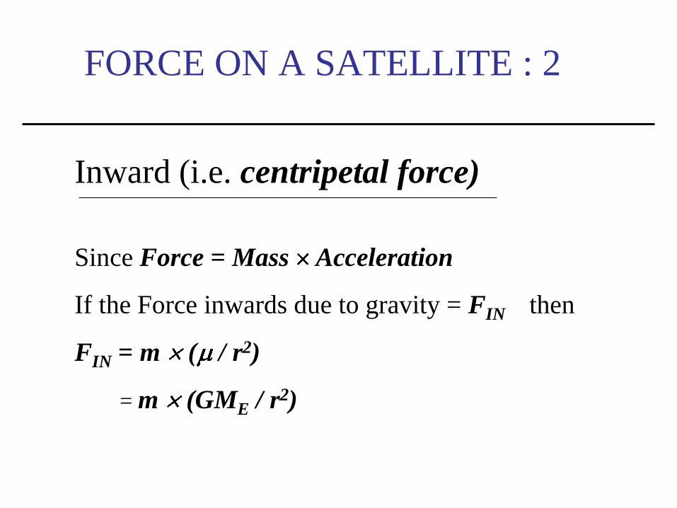
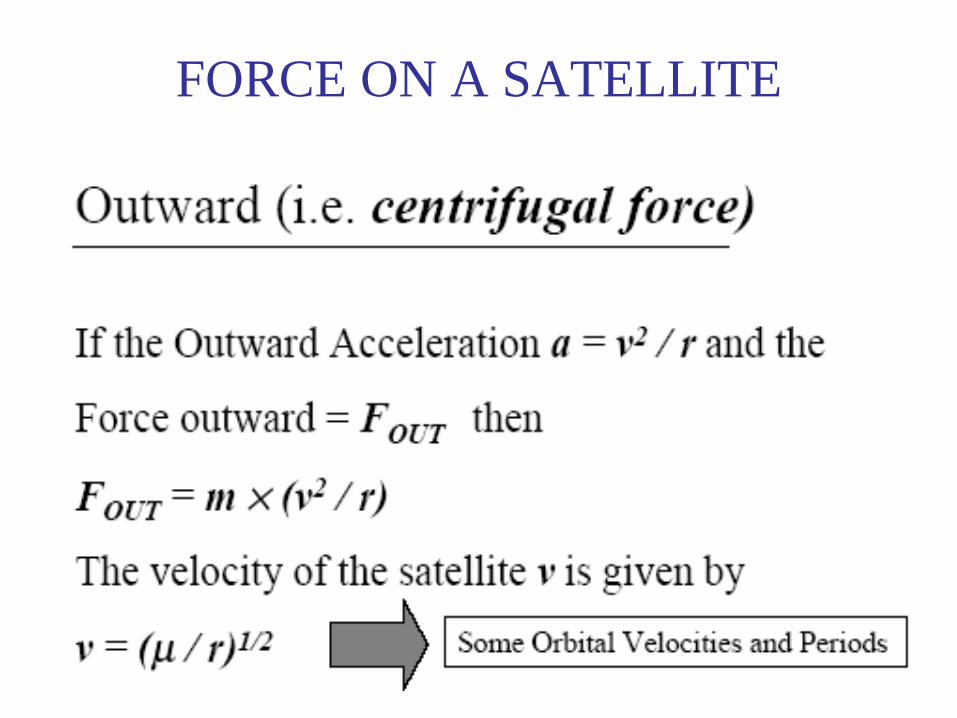
FORCE ON A SATELLITE : 2
Inward (i.e. centripetal force)
Since Force = Mass Acceleration
If the Force inwards due to gravity = FIN then
FIN = m ( / r2)
= m (GME / r2)

F1 (Gravitational
Force)
v (velocity)
Why do satellites stay moving and
in orbit?
F2 (Inertial-Centrifugal
Force)

Orbital Velocities and Periods
Satellite Orbital Orbital Orbital
System Height (km) Velocity (km/s) Period
h min s
INTELSAT 35,786.43 3.0747 23 56 4.091
ICO-Global 10,255 4.8954 5 55 48.4
Skybridge 1,469 7.1272 1 55 17.8
Iridium 780 7.4624 1 40 27.0
FORCE ON A SATELLITE

Forces acting on a satellite in
a stable orbit around the earth.
Gravitational force is inversely
proportional to the square of
the distance between the
centers of gravity of the
satellite and the planet the
satellite is orbiting, in this case
the earth. The gravitational
force inward (FIN, the
centripetal force) is directed
toward the center of gravity of
the earth. The kinetic energy
of the satellite (FOUT, the
centrifugal force) is directed
diametrically opposite to the
gravitational force. Kinetic
energy is proportional to the
square of the velocity of the
satellite. When these inward
and outward forces are
balanced, the satellite moves
around the earth in a “free fall”
trajectory: the satellite’s orbit.
If FOUT = FIN
the object is in
FREE FALL
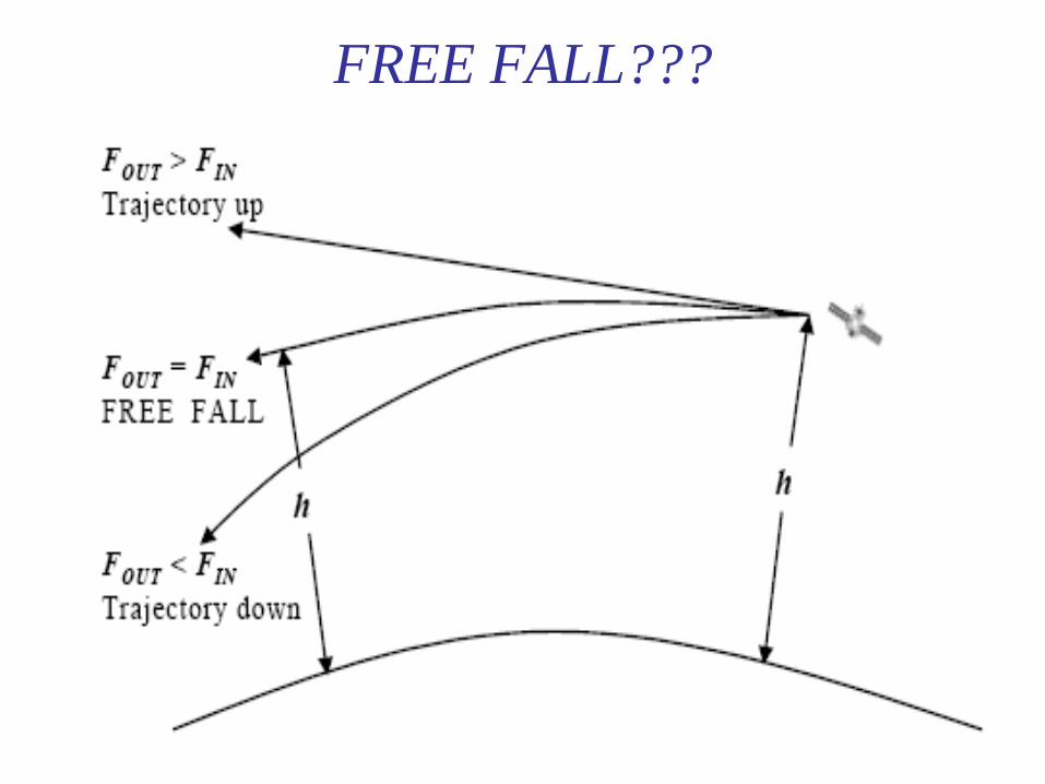
FREE FALL???

ORBIT LIMITS
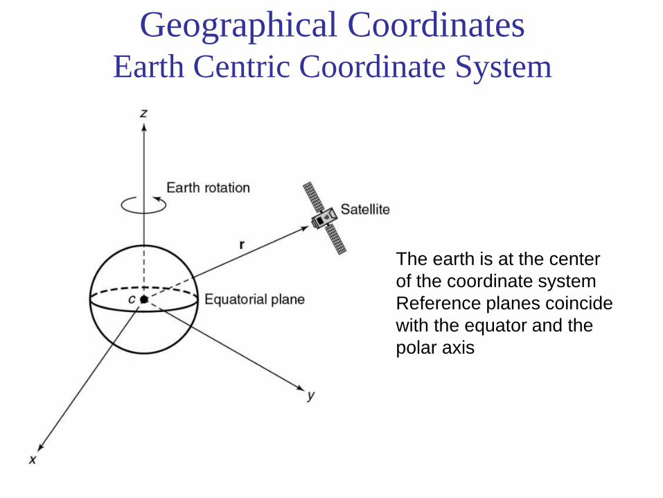
Geographical Coordinates Earth Centric Coordinate System
The earth is at the center
of the coordinate system
Reference planes coincide
with the equator and the
polar axis

Orbital Plane Coordinates
The earth is at the
center of the coordinate
system but ………
Reference is the plane
of the satellite’s orbit

Balancing the Forces
Inward Force
r
mGME
F 3
rEquation (2.7)
F
G = Gravitational constant = 6.672 10-11 Nm2/kg2
ME = Mass of the earth (and GME = = Kepler’s constant)
m = mass of satellite
r = satellite orbit radius from center of earth
r= unit vector in the r direction (positive r is away from earth)
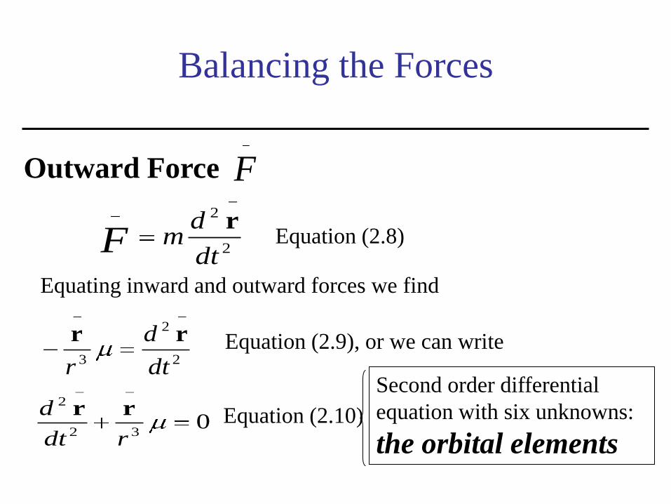
Balancing the Forces
Outward Force F
2
2
dt
dmF
rEquation (2.8)
Equating inward and outward forces we find
2
2
3 dt
d
r
rr Equation (2.9), or we can write
032
2
rdt
d rr Equation (2.10)
Second order differential
equation with six unknowns:
the orbital elements
• We have a second order differential equation
• See text for a way to find a solution
• If we re-define our co-ordinate system into polar
coordinates (see Fig.) we can re-write equation
as two second order differential equations in
terms of r0 and 0
THE ORBIT

Polar Coordinates
In the plane of the
orbit
Polar coordinate system in the plane of the satellite’s orbit. The plane of the orbit
coincides with the plane of the paper. The axis z0 is straight out of the paper from the
center of the earth, and is normal to the plane of the satellite’s orbit. The satellite’s
position is described in terms of the radius from the center of the earth r0 and the angle
this radius makes with the x0 axis, Φo.

THE ORBIT
• We have a second order differential equation
• If we re-define our coordinate system into polar coordinates
(see Fig. 2.3) we can re-write equation (2.5) as two second
order differential equations in terms of r0 and 0.
and
THE ORBIT
• Solving the two differential equations leads to six constants
(the orbital constants) which define the orbit, and three
laws of orbits (Kepler’s Laws of Planetary Motion)
• Johaness Kepler (1571 - 1630) a German Astronomer and
Scientist

KEPLER’S THREE LAWS
• Orbit is an ellipse with the larger body (earth) at
one focus
• The satellite sweeps out equal arcs in equal time
(NOTE: for an ellipse, this means that the orbital
velocity varies around the orbit)
• The square of the period of revolution equals a
CONSTANT ´ the THIRD POWER of SEMIMAJOR
AXIS of the ellipse
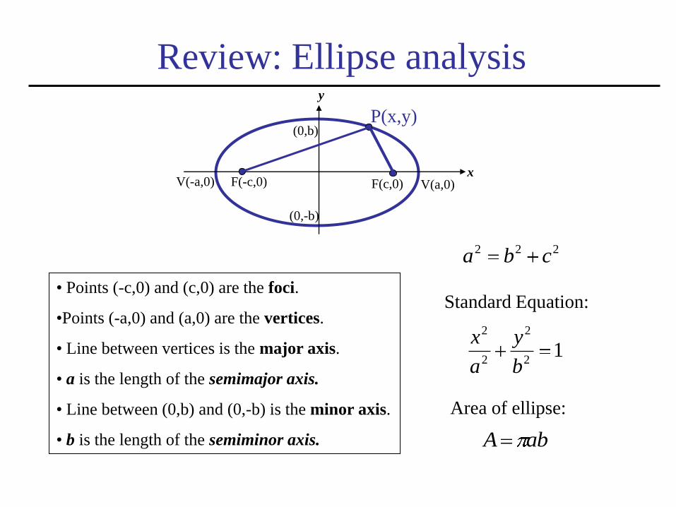
Review: Ellipse analysis
• Points (-c,0) and (c,0) are the foci.
•Points (-a,0) and (a,0) are the vertices.
• Line between vertices is the major axis.
• a is the length of the semimajor axis.
• Line between (0,b) and (0,-b) is the minor axis.
• b is the length of the semiminor axis.
12
2
2
2
b
y
a
x
222 cba
Standard Equation:
y
V(-a,0)
P(x,y)
F(c,0) F(-c,0) V(a,0)
(0,b)
x
(0,-b)
abA
Area of ellipse:

The orbit as it appears in the orbital plane, The point O is the center of the earth and the
point C is the center of the ellipse. The two centers do not coincide unless the
eccentricity, e, of the ellipse is zero (i.e., the ellipse becomes a circle and a = b). The
dimensions a and b are the semimajor and semiminor axes of the orbital ellipse,
respectively.
KEPLER 1: Elliptical Orbits
e = ellipse’s eccentricity
O = center of the earth (one
focus of the ellipse)
C = center of the ellipse
a = (Apogee + Perigee)/2

KEPLER 1: Elliptical Orbits (cont.)
Equation 2.17 in text:
(describes a conic section,
which is an ellipse if e < 1)
)cos(*1 0
0e
pr
e = eccentricity
e<1 ellipse
e = 0 circle
r0 = distance of a point in the orbit to the
center of the earth
p = geometrical constant (width of the
conic section at the focus)
p=a(1-e2)
0 = angle between r0 and the perigee
p
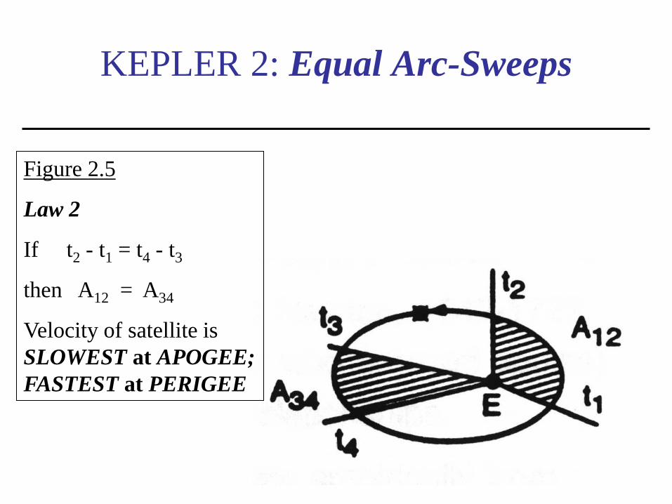
KEPLER 2: Equal Arc-Sweeps
Figure 2.5
Law 2
If t2 - t1 = t4 - t3
then A12 = A34
Velocity of satellite is
SLOWEST at APOGEE;
FASTEST at PERIGEE

Kepler’s Laws – 1 & 2
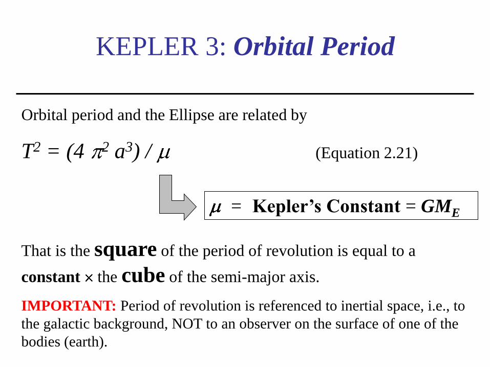
KEPLER 3: Orbital Period
Orbital period and the Ellipse are related by
T2 = (4 2 a3) / (Equation 2.21)
That is the square of the period of revolution is equal to a
constant the cube of the semi-major axis.
IMPORTANT: Period of revolution is referenced to inertial space, i.e., to
the galactic background, NOT to an observer on the surface of one of the
bodies (earth).
= Kepler’s Constant = GME

Kepler’s 3rd Law: T² = (4π²a³)/μ
μ = 3.986004418 × 10⁵ km/s²

Numerical Example 1
The Geostationary Orbit:
Sidereal Day = 23 hrs 56 min 4.1 sec
Calculate radius and height of GEO orbit: • T2 = (4 2 a3) / (eq. 2.21)
• Rearrange to a3 = T2 /(4 2)
• T = 86,164.1 sec
• a3 = (86,164.1) 2 x 3.986004418 x 105 /(4 2)
• a = 42,164.172 km = orbit radius
• h = orbit radius – earth radius = 42,164.172 – 6378.14
= 35,786.03 km

Solar vs. Sidereal Day
• A sidereal day is the time between consecutive crossings of any
particular longitude on the earth by any star other than the sun.
• A solar say is the time between consecutive crossings of any
particular longitude of the earth by the sun-earth axis.
– Solar day = EXACTLY 24 hrs
– Sidereal day = 23 h 56 min. 4.091 s
• Why the difference?
– By the time the Earth completes a full rotation with respect to an
external point (not the sun), it has already moved its center
position with respect to the sun. The extra time it takes to cross
the sun-earth axis, averaged over 4 full years (because every 4
years one has 366 deays) is of about 3.93 minutes per day.

LOCATING THE SATELLITE IN
ORBIT: 1
Start with Fig. 2.6 in Text o is the True
Anomaly
See eq. (2.22)
C is the
center of the
orbit ellipse
O is the
center of the
earth
NOTE: Perigee and Apogee are on opposite sides of the orbit

LOCATING THE SATELLITE
IN ORBIT
• Need to develop a procedure that will allow the
average angular velocity to be used
• If the orbit is not circular, the procedure is to use a
Circumscribed Circle
• A circumscribed circle is a circle that has a radius
equal to the semi-major axis length of the ellipse and
also has the same center
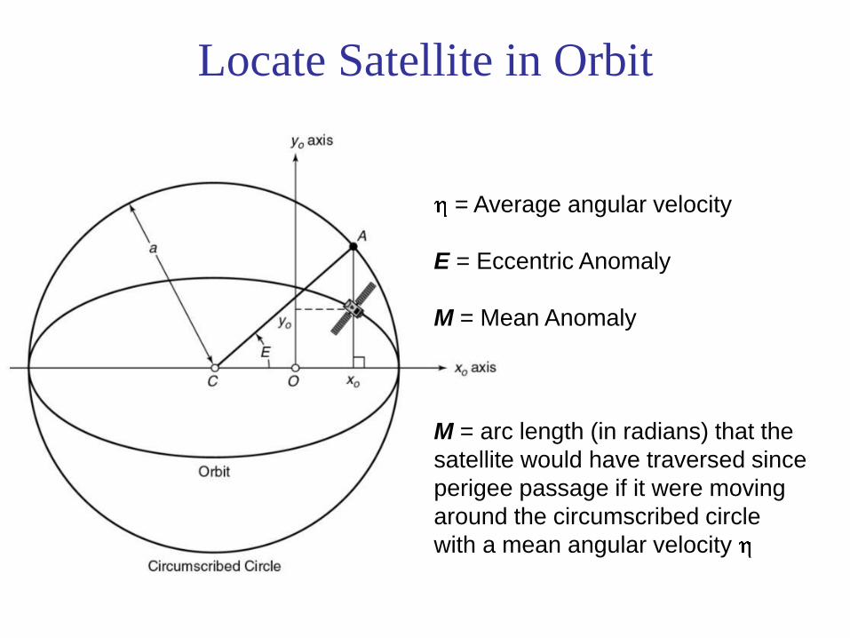
Locate Satellite in Orbit
= Average angular velocity
E = Eccentric Anomaly
M = Mean Anomaly
M = arc length (in radians) that the
satellite would have traversed since
perigee passage if it were moving
around the circumscribed circle
with a mean angular velocity
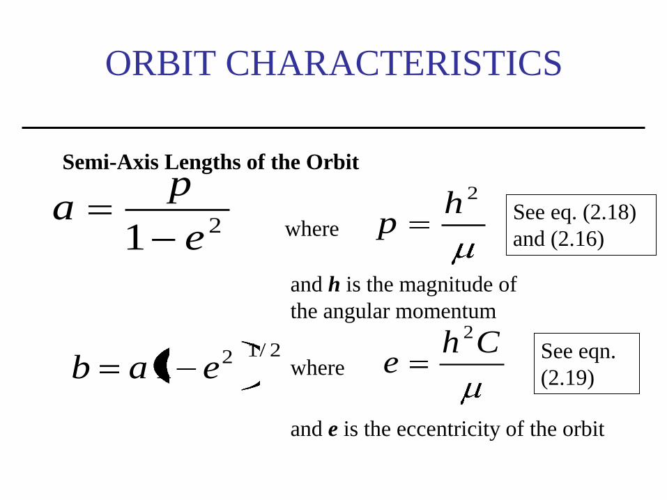
ORBIT CHARACTERISTICS
Semi-Axis Lengths of the Orbit
21 e
pa
where
2hp
and h is the magnitude of
the angular momentum
See eq. (2.18)
and (2.16)
2/121 eab where Ch
e2
See eqn.
(2.19)
and e is the eccentricity of the orbit
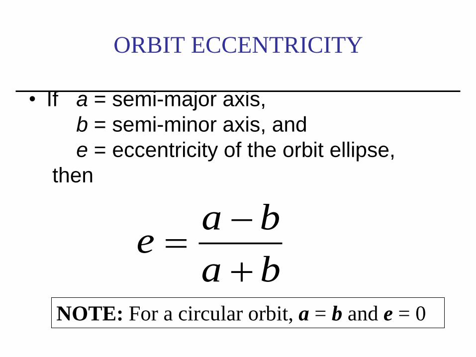
ORBIT ECCENTRICITY
• If a = semi-major axis,
b = semi-minor axis, and
e = eccentricity of the orbit ellipse,
then
ba
bae
NOTE: For a circular orbit, a = b and e = 0
Time reference
• tp Time of Perigee = Time of closest
approach to the earth, at the same time, time
the satellite is crossing the x0 axis, according to
the reference used.
• t- tp = time elapsed since satellite last passed
the perigee.

ORBIT DETERMINATION 1:
Procedure:
Given the time of perigee tp, the eccentricity e and the length of the semimajor axis a:
• Average Angular Velocity (eqn. 2.25)
• M Mean Anomaly (eqn. 2.30)
• E Eccentric Anomaly (solve eqn. 2.30)
• ro Radius from orbit center (eqn. 2.27)
• o True Anomaly (solve eq. 2.22)
• x0 and y0 (using eqn. 2.23 and 2.24)