union special 57700r, s, t, u & v
DESCRIPTION
Instruction manual for seewing machine Union Special class 57700TRANSCRIPT
Zéizieiz_.3cia®LEWIS’ . COLUMBI MACHINES
STYLES
57700R57700557700T57700U57700V
CLASS 57700
ADVANCED HIGH SPEEDFIFTY THOUSAND SERIES
FLAT BED MACHINESWITH
ELASTIC METERING DEVICE
UNION SPECIAL CORPORATION
FINEST QUALITY
A
.b
CATALOGNo.
131N
CHICAGO

Catalog No, 131 N
INSTRUCTIONS
FOR
ADJUSTING AND OPERATING
LIST OF PARTS
CLASS 57700
Styles
57700 R 57700 T57700 S 57700 U
57700 V
First Edition
Copyright © 1974By
Union Special CorporationRights Reserved in All Countries
UNION SPECIAL CORPORA TIONINDUSTRIAL SEWING MACHINES
CHICAGO
Printed in U.S.A.
January, 1979
2

IDENTIFICATION OF MACHINES
[ac1i UNION SPECIAL machine is identified by a Style number which is on thename plate on the machine. Style numbers are classified as Standard and Special.Standard Style numbers have one or more letters suffixed, but never contain theletter “Z “. Example: “Style 57700 R ‘. Special Style numbers contain the letter “ZWhen only minor changes are made in a standard machine, a “Zfl is suffixed to theStandard Style number. Example: ‘ Style 57700 RZ
Styles of machines similar in construction are grouped under a Class numberwhich differs from the Style number, in that it contains no letters, Example: “Class57700”.
APPLICATION OF CATALOG
This catalog applies specifically to the Standard Styles of machines as listedherein. It can also be applied with discretion to some Special Styles of machinesin this Class. Reference to direction, such as right, left, front, back, etc,, aregiven from the operatorvs position while seated at the machine. Operating directionof handwheel is toward the operator,
STYLES OF MACHINES
Advanced High Speed, Two and Three NeedlesAbreast, One Looper, Flat Bed Medium Throw IV[achines, Needle Bearing Needle Bar Drive, Light Weight Presser Barand Needle Bar Driving Mechanism, Single Reservoir, Enclosed PositiveAutornaticLubricating System, Filtered Oil Return Pumps for Head and Base, Lateral LooperTravel, Double Disc Take-up, Large Handwheel and Improved Belt Guard, Prepared for use with Knee Press for Presser Foot Lifter, Equipped with Disc ThreadTensions, Maximum Work Space to Right of Needle Bar 8 1/4 Inches (209.55 mm).
57700 R Two needle plain feed machine, for attaching elastic in long lengths, 1/4to 1 1/2 inches (6. 35 to 38.10 mm) wide, to rayon, silk, cotton, nylon andwool, flat, warp and ribbed knit garments and for similar operations on lightto medium weight materials. Equipped with adjustable top driven meteringdevice and under trimmer. Standard gauge Nos. 8 and 12. Seam specification406-LSa-1. Type 121 GBSneedle. Maximumrecommended speed 5500 R.P.M.
57700 S Three needle plain feed machine, for attaching elastic in long lengths, 3/8to 1 1/2 inches (9.52 to 38,10 mm) wide, to rayon, silk, cotton, nylon and wool,flat, warp and ribbed knit garments and for similar operations on light to mcclium weight materials, Equipped with adjustable top driven metering device andunder trimmer, Standard gauge No, 16 only, Seam specification 407—LSa-1,Type 121 GBS needle, Maximum recommended speed 5500 H, P. M,
57700 T Two needle differentialfeed machine, for attaching elastic in long lengths,3/16 to 1 1/2 inches (4,76 to 38,10 mm) wide, to rayon, silk, cotton, nylon andwool, flat, warp and ribbed knit garments and for similar operations on light tomedium weight materials. Equipped with adjustable top driven metering device,under trimmer and thumbscrew adjusted offset differential feed. Standard gaugeNo. 8 only. Seam specification 406-LSa-1. Type 121 GES needle, Maximumrecommended speed 5500 H, P. IVI,

STYLES OF MACHINES (C ontinued)
57700 U Three needle differential feed machine, for attaching elastic in long lengths,3/8 to 1 1/2 inches (9,52 to 38,10 mm) wide, to rayon, silk, cotton, nylon andwool, flat, warp and ribbed knit garments and for similar operations on lightto medium weight materials, Equipped with adjustable top driven metering de—vice, under trimmer and thumbscrew adjusted offset differential feed. Standardgauge No, 16 only. Seam specification 407 —LSa-1, Type 121 GBS needle, Maximum recommended speed 5500 R,P,M.
57700 V Same as 57700 R, except without under trimmer, but fitted withbody folderfor turning body of garment upwardly. Standard gauge Nos. 8 and 12, Seamspecification 406-LSb-1, Type 121 GBS needle, Maximum recommended speed5500 R, P. lvi,
NEEDLES
Each UNION SPECIAL needle hasboth a typeand sizenumber. The typenumber
denotes the kind of shank, point, length, groove, finish and other details. The size
number, stamped on the needle shank, denotes largest diameter of blade, measured
in thousandths of an inch, midway between shank and eye. Collectively, type and
size number represent the complete symbol, which is given on the label of ailneedlespackaged and sold by Union Special.
The standard recommended needle for the machines covered here is Type121 GBS. Below is the description and sizes available of the recommended needle,
Type No, Description and Sizes
121 GBS Round shank, round point, short, single groove, struck groove, spotted,ball point, chromium plated - available in sizes 065/025, 070/027,075/029, 080/032, 090/036, 100/040.
To have needle orders promptly and accurately filled, an empty package, asample needle, or the type and size number should be forwarded. Use descriptionon label. Acompleteorderwould read: “1000 eedles, Type 121 GBS, Size 080/032”.
Selection of proper needle size is determined by the size of thread used, Thread
should pass freely through needle eye in order to produce a good stitch formation,
Success in the operation of UNION SPECIAL machines can be secured only byuse of needles packaged under our brand name, j, which is backed by areputation for producing highest quality needles in materials and workmanship formore than three-quarters of a century.
4

THREADING AND OILING DIAGRAM
Thread machine as indicated, The looper threading has been enlarged for clarity, The RIGHT needle thread should be threaded through the uppermost thread tensioner and eyelet holes closest to the bed casting. The machine illustrated is a twoneedle machine, but the three needle machines are threaded in substantially thesame manner.
The oil has been drained from the machine before shipping, so the reservoirmust be filled before starting to operate, To fill machine with oil, remove plugscrew in top cover and add oil until the needle of oil gauge (A) is in gold band marked“FULL”, Use a straight mineral oil of a Saybolt viscosity of 90 to 125 seconds at100 Fahrenheit. Maintain oil level in “OPERATE” position and add oil when needleis in gold band marked “LOW”. The machine is automatically lubricated and nooiling other than keeping the main reservoir filled is necessary.
Excessive oil in the main reservoir may be drained at the plug screw (B).
U
,1
/
L.
Fig. 1
5

i.NS’I’ RUC’iYONS l’()I VIiC’i IANICS
i . U KR1(ATION
(AUTTOP! Oil has been drained from the main reservoir before shipment, so the
reservoir must be filled to the proper level before beginning to operate. Run machineslowly for several minutes to distribute the oil to the various parts, Full speed
operation can then be expected without damage.
RECOMMENDEI) OIL
Oil may be drained from main reservoir byremoving plug screw (C, Fig. 2) located belowthe cloth plate at front of the machine,
NOTE: Looper avoid and feed lift eccentricsreceive oil thru the mainshaft, so when assembling be sure oil holes in the eccentric lines upwith oil holes in mainshaft when spot screw is
uL
in timespot. See paragraph on “Changing Stitch Length” for repacking feed rocker
sealed greased bearings.
OIL GAUGE
The oil gauge is set at the factoryto show the proper oil level in the reservoir,
Should an adjustment become necessary, however, the following steps should befollowed:
1. Place the machine upright on a level table or bench,
2. Remove the oil reservoir plug screw (C, Fig. 2) and tip machine forward
to drain oil from the reservoir.
3, Make sure all oil is drained from main reservoir,
Use a straight mineral oil of0a Saybolt viscosity of 90 to 125 seconds at 100 Fahrenheit inthe main reservoir, This is equivalent to UnionSpecial specification No. 175 . Fill main reservoir at plug screw in upper crank chambercover (A, Fig. 2) and check oil level at gauge(B). Oil is at maximum level when needle is ingold band marked “Full”. Oil should be addedwhen needle is in gold band marked “Low”.
CAUTION! It is important that these machinesnot be over filled.
It is recommended that a new machine, orone that has been out of service for an extendedperiod of time, be lubricated as follows: Removethe head cover, clean out lint and directly oil theneedle bar link and the needle bar. Replace headcover as no further hand oiling will be required.Run machine slowly for several minutes todistribute oil to the various parts.
AG
/•L
‘,•-•
y
.
4.-’%_.
l,. //
Fig. 2
6
Cli GA [J( (Continued)
4, Remove lower crank chamber cover, located at the back of the machine,
5, i’ill main reservoir to a level even with the bottom contour of the knee pressshaft bushing (I), Vig, 2),
6, Loosen lock nut (I) on calibrating screw (F), and turn the screw to the leftor right until the gauge needle rests in the middle of the gold band markedhIJOwH
7 Tighten lock nut (F) and replace plug screw (C).
8, Add oil so that gauge needle rests in the middle of the goldband marked “FULL”,
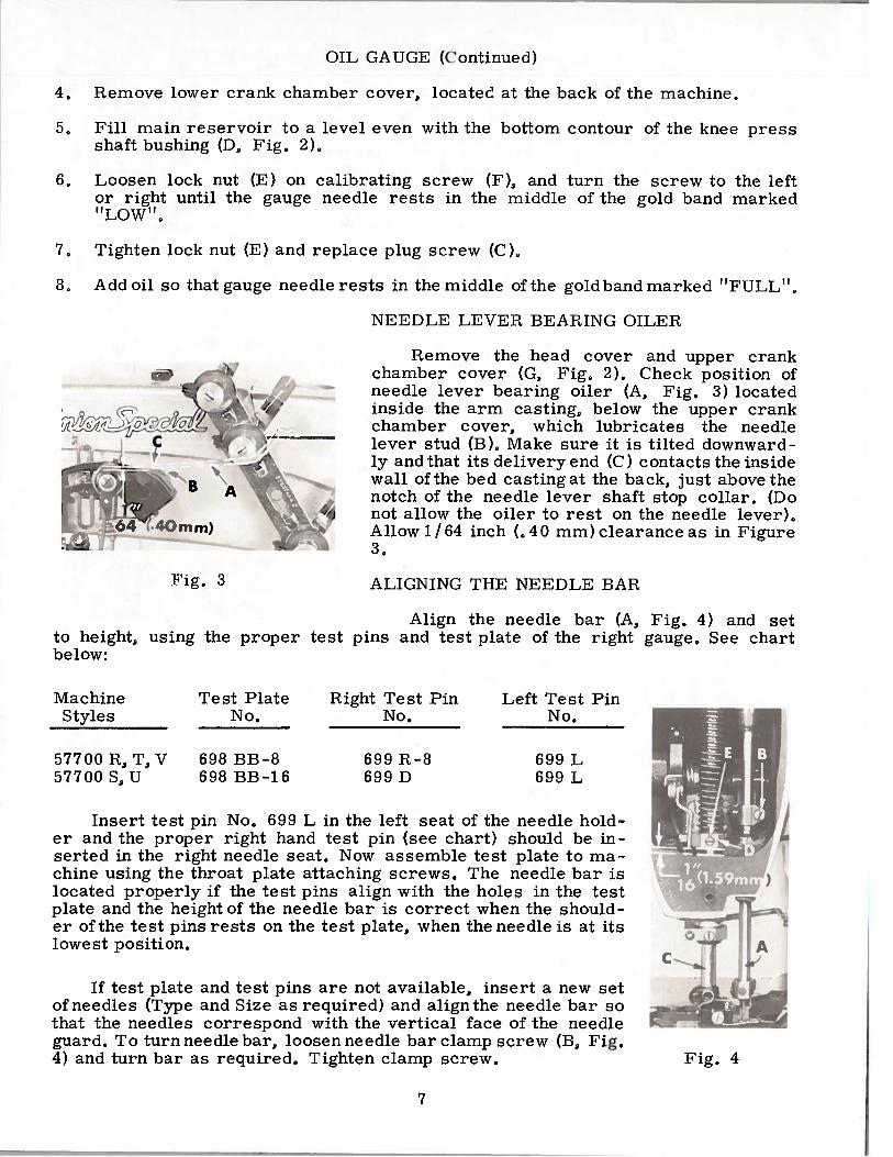
NEEDLE LEVER BEARING OILER
Remove the head cover and upper crankchamber cover (G, Fig, 2), Check position of
— needle lever bearing oiler (A, Fig. 3) locatedinside the arm casting, below the upper crankchamber cover, which lubricates the needlelever stud (B), Make sure it is tilted downwardly and that its delivery end (C) contacts the insidewall of the bed casting at the back, just above thenotch of the needle lever shaft stop collar, (Do
% not allow the oiler to rest on the needle lever),Allow 1/64 inch (,40 mm) clearance as in Figure3,
ALIGNING THE NEEDLE BAR
Align the needle bar (A, Fig, 4) and setto height, using the proper test pins and test plate of the right gauge, See chartbelow:
Machine Test Plate Right Test Pin Left Test PinStyles No, No. No,
57700 R, T, V 698 BB-8 699 R—8 699 L57700 5, U 698 BB-16 699 D 699 L
Insert test pin No, 699 L in the left seat of the needle holder and the proper right hand test pin (see chart) should be inserted in the right needle seat, Now assemble test plate to machine using the throat plate attaching screws, The needle bar islocated properly if the test pins align with the holes in the testplate and the height of the needle bar is correct when the shoulder of the test pins rests on the test plate, when the needle is at itslowest position.
If test plate and test pins are not available, insert a new setof needles (Type and Size as required) and align the needle bar sothat the needles correspond with the vertical face of the needleguard, To turn needle bar, loosen needle bar clamp screw (13, Fig,4) and turn bar as required, Tighten clamp screw,
Fig. 3
Fig. 4
7
YNC1 lIlONIZINC iX)OPi1 AINI) NiEI)iE 1VI()TTONS
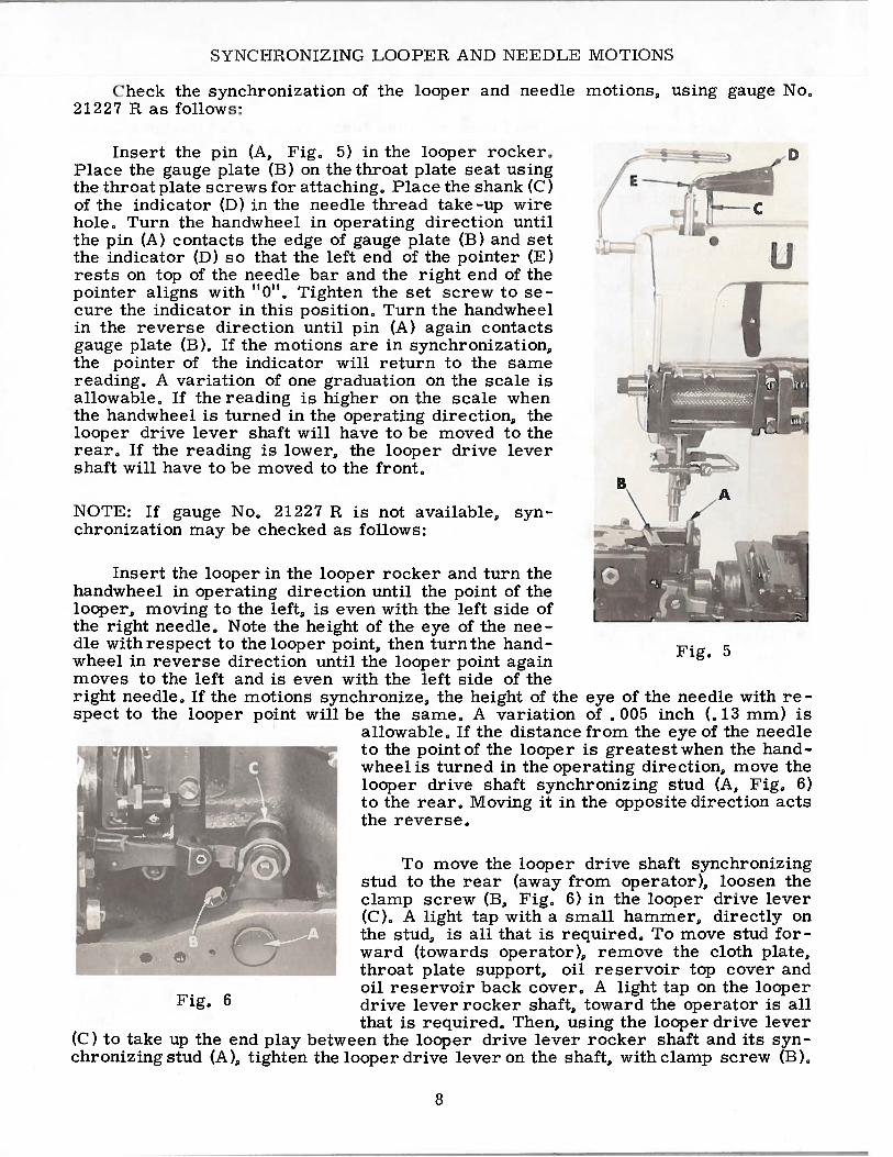
Check the synchronization of the looper and needle motions, using gauge No,21227 H as follows:
insert the pin (A, 1’ig, 5) in the looper rocker,Place the gauge plate (13) on the throat plate seat using
_______
the throat plate screws for attaching. Place the shank (C)of the indicator (D) in the needle thread take-up wirehole, Turn the handwheel in operating direction untilthe pin (A) contacts the edge of gauge plate (B) and setthe indicator (ID) so that the left end of the pointer (E)rests on top of the needle bar and the right end of thepointer aligns with b0I, Tighten the set screw to secure the indicator in this position, Turn the handwheelin the reverse direction until pin (A) again contactsgauge plate (B), If the motions are in synchronization,the pointer of the indicator will return to the samereading, A variation of one graduation on the scale isallowable. If the reading is higher on the scale whenthe handwheel is turned in the operating direction, thelooper drive lever shaft will have to be moved to therear, If the reading is lower, the looper drive levershaft will have to be moved to the front,
NOTE: If gauge No, 21227 R is not available, synchronization may be checked as follows:
Insert the looper in the looper rocker and turn thehandwheel in operating direction until the point of thelooper, moving to the left, is even with the left side ofthe right needle. Note the height of the eye of the needle with respect to the looper point, then turnthe hand- Fi 5wheel in reverse direction until the looper point againmoves to the left and is even with the left side of theright needle, If the motions synchronize, the height of the eye of the needle with respect to the looper point will be the same, A variation of . 005 inch (.13 mm) is
allowable, If the distance from the eye of the needleto the point of the looper is greatest when the hand-wheel is turned in the operating direction, move thelooper drive shaft synchronizing stud (A, Fig, 6)to the rear, Moving it in the opposite direction actsthe reverse,
To move the looper drive shaft synchronizingstud to the rear (away from operator), loosen theclamp screw (B, Fig, 6) in the looper drive lever(C), A light tap with a small hammer, directly onthe stud, is all that is required, To move stud forward (towards operator), remove the cloth plate,throat plate support, oil reservoir top cover andoil reservoir back cover, A light tap on the looper
Fig. 6 drive lever rocker shaft, toward the operator is allthat is required, Then, using the looper drive lever
(C) to take up the end play between the looper drive lever rocker shaft and its synchronizing stud (A), tighten the looper drive lever on the shaft, with clamp screw (B),
4FcU
8

SY N( II I( ) N JZ [Nc; I OO I l A NI) NEE I )JE IVIOTIONS (( ontinued)
Withthe looper at the extreme right endof its travel, check the location of the rightlooper connecting rod bearing, using gaugeNo, 21227 I)( (A, I’ig. 7), Place the holein gauge over threaded stud and the left inside edge of the gauge should locate againstthe left side of the looper rocker cone (B),If adjustment is necessary, loosen clampscrew (C), reposition looper drive lever(I)) as required and retighten clamp screw,
NOTE: Whenever looper drive lever isrepositioned, apply pressure to rear toassure that H0l1 ring is compressed, pre
venting oil leakage, and take up all the end play.
SETTING THE LOOPER
Insert a new needle in the right needle seat, typeand size as specified. If the looper gauge is 3/16 inch(4,76 mm), for example, set the looper (A, Fig, 8) sothe distance from the center of the right needle (B) tothe point of the looper is 3/16 inch (4,76 mm) when thelooper is at its farthest position to the right. Loopergauge No. 21225-3/16 can be used advantageously inmaking this adjustment, Refer to chart for loopergauge setting and looper gauge number applicable tomachine Style, If adjustment is required, loosen nut(C) (it has a lefthand thread) and nut (ID) on connectingrod (E), turn the connecting rod forward or backwardto obtain specified dimension, Retighten both nuts,first nut (D) and then nut (C), Make sure the left balljoint is in vertical position and does not bind after Fig, 8adjustment.
Machine Looper Gauge Looper GaugeStyle Setting Number
57700 R—8 7/32 inch (5.56 mm) 21225-7/3257700 S-16 3/16 inch (4.76 mm) 21225-3/1657700 T—8 7/32 inch (5.56 mm) 21225-7/3257700 U—l6 3/16 inch (4.76 mm) 21225-3/1657700 V—8 7/32 inch (5.56 mm) 21225-7/3257700 V-12 7/32 inch (5.56 mm) 21225-7/32
The looper is set correctly in line-of-feed, if, as it moves to the left, behindthe needle, its point brushes, but does not pick at the rear of the needle, If adjustment is necessary, loosen lock screw (F, Fig. 8) and turn stop screw (G) as required, Turning stop screw clockwise sets the looper to the rear and turning itcounterclockwise acts the reverse, Holding looper to the front while making thisadjustment may prove helpful, Tighten lock screw when setting is obtained and recheck the adjustment.
Pig. 7
9

S I IT IN G I IE I( [-[T 01’ NEE 1)1 E I A. It
‘l’hc height of the needle bar should be correct if proper test plate and test pinswere used to ‘align’ needle bar, Tf not, the height of the needle is correct when thetop of its eye is 3/64 inch (1.19 mm) below the underside of the looper., with thelooper point flush with the left side of the left needle. If adjustment is necessary,loosen screw (K, Fig, 4) and move needle bar (A) up or down as required and retighten screw, (are should be taken not to disturb the alignment of the needle barwhen moving it up or down,
rIhe needles are to have equal clearance on the right and left sides of needleslots in throat plate, The descending needles must be deflected alike on the backof the looper,
SETTING TIlE DIFFERENTIAL FEED DOG(FOR STYLES 57700 T and U)
The differential feed dog should be set to rise thedepth of a full tooth or approximately 3/ 64 inch (1. 19mm) B
abovethe throatplate at highestpoint of travel, Adjust- / F
ment can be made by loosening screw (A, Fig, 9 or IB, Fig, 12), raise or lower feed dog (13, Fig. 9)andretighten screw, At maximum feed travel, the feed ‘ I cdog should clear the forward end of throat plate by1/32 inch (,79 mm) Fig. 10; also parallel to the top Esurface of throat plate and centered in throat plate slot “
across-the-line-of-feed, Adjustments can be made by Fi 9loosening set screws (A, Fig, 10 or C, Fig. 12),permitting the differentialfeed bar (B, Fig, 10 or D, Fig, 12), to be moved forward,backward or rotated as needed to acquire the aforementioned conditions, Under extreme circumstances it may be necessary to shift the complete feed mechanismslightly, to the right or left to meet these conditions, This can be done by looseningcollars (C, Fig, 10) and moving feed rocker (D); retighten collars and set screwssecurely, Make sure the feed rocker arm does not bind after making this adjustment,
SETTING THE MAIN FEED DOG(FOR STYLES 57700 T and U)
The main feed dog should also be set to rise thedepth of a full tooth above the throat plate at highestpoint of travel and centered in the slots of throatplate at maximum feed travel.
To raise or lower main feed dog, loosen Allenscrew (C. Fig. 9) allowing feed dog holder (D) tobe moved, NOTE: Screw (E) must be set to supportthe main feed dog (F) when specified height is obtained, Retighten screw (C).
NOTE: Any change in the setting of main feed dogheight will necessitate a check of the rear needleguard setting.
To center main feed dog in the slots of throatplate across-line-of-feed, loosen screws (A, Fig.11), move feed dog to the right or left as required,retighten screws. To center the feed dog in-line-
of-feed, loosen nut (A, Fig, 12) and move feed rocker forward or backward as needed, retighten nut,
1/ H LrVrl
(.79mm) TT—a
Fig, 10
10

SE rj,r) [N ( ‘I’] IF iVIA TIN l’I I I) I )( )( (( ontinuecl)(I’OR ‘T YIiS 57700 T and U)
NOl’I Ilecheck differential feed clog setting.
SETTING f[{F I )II’FERENTLAL l’E1L) IATIO(FOR S1’Yi ES 57700 ‘I and U)
rIhe differential feed ratio is set byloosening screw (B, Fig, 11) and move thesvieetoi slide (C) to the desired position.The screw and selector slide are accessiblethrough the top of the cloth plate on the leftside, Moving the differential feed selectorslide (C) toward the front increases theamount of differential and moving it toward the rear decreases the amount ofdifferential feed, Retighten screw.
These styles of machines have aninfinite stretching ability and a gatheringratio of up to 2 to 1, with the main feeddog set at 9 stitches per inch, Turn machine by hand, making sure the differentialfeed dog clears the main feed dog at theback end of its stroke,
SETTING TI-fE FEED DOG(FOR STYLES 57700 R, 5, V)
Set the feed dog (A, Fig.13) in the throat plate (B) sothere is equal clearance onall sides, See that the tips ofthe teeth extend the depth of atooth or approximately 3/64inch (1.19 mm) above thethroat plate and are parallelwith the throat plate at highpoint of travel, Adjust thesupporting screw (C), underthe feed dog, to maintain thissetting, Screw (D) is used tohold feed dog in position,
If feed dog teeth are notparallelwith the throat plate,loosen nut (A, Fig. 14) and Fi r 12turn screw (B) clockwise to g.
lower the front teeth and counterclockwise to raise the front teeth. Retighten nut whenfeed dog is set properly,
Should it be necessaryto move the feed dogto theleft or right, loosen screws (A, Fig, 15), which holdthe feed rocker (B) onto the feed rocker shaft (C) andmove feed rocker to desired position then retightenthe screws, Make sure the feed rocker arm (D) doesnot bind after making this adjustment,
When handwheel is turned in the operating direction, feed dog should have equal clearance at both ends of throat plate slots,with feed travel set to desired stitch length.
Irig, 11
A
Fig, 13
11

SE’ !“I’i N( ‘I’! I I I’EiI) DOG (Continued) (FOR STYLES 57700 R, 5, V)
Should it he necessary to move the feed clog forward or backward, loosen nut (i,I’ig. 1 5) which clamps the feed rocker arm to the feed rocker and move feed rockerforward or backward as necessary. Retighten nut,
Si rlnI ‘1 N C TI! I I A Il NEE Di E (WAR 1)(I’OI STYTES 57700 T and U)
Set the rear needle guard (D, Fig. 11) horizontally sothat it does not quite contact the rear of the right needle(E) when at its most forward point of travel. A clearanceof .005 inch (,13 mm) is permissible, It should be set aslow as possible, yet have its vertical face approach within about 3/64 inch (1.19 mm) of the needle, until the pointof the looper (I’), moving to the left, is even with the needle, To move needle guard, merely loosen screw (G), moveneedle guard as required, and retighten screw,
NOTE Adjustment of the rear needle guard will necessitate a check of the mainfeed dog height,
SETTING TI-IE REAR NEEDLE GUARD (FOR STYLES 57700 R, S, V)
Set the rear needle guard(C, Fig, 14) horizontally so thatit does not quite contactthe rearof the right needle (D) when atits most forward point of travel.A clearance of ,005 inch (,13mm) is permissible, It shouldbe set as low as possible, yethave its vertical face approachwithinabout 3/64 inch (1. 19 mm)of the needle, until the point ofthe looper (E), moving to theleft, is even with the needle, Tomove needle guard forward orbackward, merely loosen screw(F), move needle guard as re—quired, and retighten screw, Toraise or lower needle guard,
to lower needlescrew (F) after
NOTE: A change in stitch length will require a change in rearneedle guard setting,
SETTING FRONT NEEDLE GUARDkiT]
Set the front needle guard so that itpushes the left needle back Itoward the path of the looper as it moves behind the needle, Thelooper may brush but not pick at the left needle, It should be setas low as possible, yet have its vertical face push the left needleuntil the point of the looper is just past the left side of the leftneedle, The front needle guard should not contact the rear needleguard or right needle at any time, Tomove guardforwardor backward, merely loosen screws (H, Fig, 11) move needle guard astighten screws, To raise, lower or rotate needle guard, loosen screws (J), moveguard and retighten screws after guard is properly set,
Fig, 14
Fig. 15
loosen screw (F), and turn screw (G) clockwiseguard and counterclockwise to raise it, Retightenguard is properly set,
Fig. 16
required and re
12

SETr1 INC F HON T NEEDLE C1JAR D (Continued)
I\JOrlE: A change in stitch length WILL NOT require a change in front needle guardsetting.
C’ITANGTNG STITCh J}(f[I
Set the stitch to required length. This is accomplished by loosening lock nut(F, Fig. 15) 1/2 turn (it has a left thread) on the end of the stitch regulating stud andturning the stitch adjusting screw (G) located under the left end of the cloth plate inthe head of the main shaft (H) which is marked with “L” and “5”. Turning the screwin a clockwise direction shortens the stitch (moves stitch regulating stud toward the“S”) and turning it in a counterclockwise direction lengthens the stitch (moves stitchregulating stud toward the “L”). Retighten the lock nut securely. To prevent destructive damage to the feed drive bearing, the key screw (J) must engage the “uflshaped key slot in the ferrule (K).
On Styles 57700 R, S and V, the feed rocker assembly may require lubricationafter years of operation at the feed rocker needle bearings (L and M, Fig, 15). Thiscan be accomplished by loosening Allen screw (N) and remove shaft (P). Whenpacking needle bearings, parts must be clean and grease should be applied directlyfrom the tube to avoid contamination, Tube of grease can be supplied under partNo, 28604 P. Replace shaft inserting tapered end first and tighten screw (N).
THREAD TENSION RELEASE
The thread tension release is set correctly when it begins to function as thepresser foot is raised to within 1/8 inch (3,17 mm) of the end of its travel and isentirely released when the presser foot has reached its highest position,
If adjustment is needed, loosen tension release lever screw (A, Fig, 16) located at the back of the machine and move tension disc separator as required, Re-tighten screw, After adjustment there should be no binding at any point,
SETTING HEIGHT OF PRESSER BAR
The height of the presser bar (C, Fig, 4) is set correctly if it is possible toremove the presser foot when the foot lifter lever (B, Fig, 16) is fully depressed,Also there should be approximately 1/16 inch (1,59 mm) clearance between lowersurface of the presser bar connection and guide (D, Fig, 4) and the bottom surfaceof head opening in the bed when the foot lifter lever is released and the presser footresting on the throat plate, with the feed dog down below the throat plate,
If adjustment is needed, turn handwheel in operating direction until the needlebar is in the low position. Loosen screw (E, Fig. 4) then, while holding presserfoot down on the throat plate surface, pry up presser bar connection and guide witha screwdriver to obtain the 1/16 inch (1.59 mm) setting and retighten screw. Checksetting by turning handwheel so that needle bar is in its high position and see ifpresser foot can be removed as mentioned in previous paragraph.
METERING DEVICE ADJUSTMENTS
The metering device MUST operate freely with the connecting rod assembly(A, Fig. 17) positioned at any point in the clutch drive lever (B) and the clutchrocker shaft lever (C).
NOTE: Once the metering device has been adjusted properly, the (2) threaded holesin the clutch rocker shaft lever are provided for positioning the connecting rodassemblyas near VERTICAL aspossible whenEXTREME right or left positionsin the clutch drive lever are being used,
13

iVI VTE1{1 NC DEVICE Al)JUSTMEN TS (Continued)
If adjustment is required, first, check and/or adjust the connecting rod assem
bly, ‘Ihere should be 2 inches (50. S rum) between centerline of screw and centerline
of bail stud (11g. 17). Reposition clutch drive lever (B) on the needle lever shaft,
up or down as required, so the connecting rod assembly does not bind, moving to
either extreme of travel while turning handwheel in the operating direction. The
connecting rod assembly should have a SLIGHT SNAKE in all positions. The clutchdrive lever may require a slight adjustment when moving connecting rod assembly
as described in ‘Noil?”
I_.
4--’
utr .
G
B V-
AN i) O.8mm)
Fig. 17
As sewing conditions require, moving the connecting rod assembly to the left,
in the clutch drive lever, increases the amount of elastic being metered; moving itto the right, decreases the amount of elastic being metered.
The clutch brake is set at the factory, though a considerable change in stitch
length may necessitate a change in the amount of brake pressure required to eliminate overthrow of the metering device at high speeds. Should adjustment be nec
essary, loosen nut (D, Fig. 17) and turn bushing (E) clockwise to lessen clutch
overthrow (viewed from the handwheel end of machine); turning bushing counterclock
wise acts the reverse. NOTE: Apply only enough brake pressure to eliminate over
throw. Too much brake pressure will create excessive heat and wear to the meter
ing device mechanism. Retighten nut (D).
Tension on the metering device pressure roller (F) can be adjusted by loosen
ing set screws and rotating hexagon collar (C) as required, retighten set screws.
Normal setting about 1/4 turn.
The tape guides (H) are set correctly when they hold the elastic to the left
against the presser foot guide.
UNDERTRIMMER ADJUSTMENTS(FOR ALL STYLES EXCEPT 57700 V)
The lower knife (A, Fig, 18) should be set with cutting edge flush with throatplate surface, at approximately a one degree shear angle (Fig, isA). Adjustment canbe made by loosening hexagonal head screw (B, Fig. 18) permitting lower knife to bemovedup or down; loosening (2) screws (C) will allow positioning of lower knife block(D) to obtainthe proper shear angle. Never loosen screw (E) foradjusting purposes,it should remain tight at all times, After adjustments are made, tighten screws (Band C) securely.
-
D
-I
Si
E C
I.
14

II NI )I R’IIUIVIMER ADJUST TS (Continued)(I’o I ALL S rfyfl5 ECE PT 57700 V)
rihe upper knife (I, I’ig. 18) should be set to align its cutting edge with thecenterline of right needle and to engage lower knife for full cutting length. This canbe accomplished by loosening screw (G) permitting upper knife to be moved forward or rearward; loosen screws (II and J) and turn eccentric (1K) as required toobtain proper positioning for up and down movements, Retighten screws securely.
--I’
Fig. 18A
Lower knife is spring pressed against upper knife. Pressure can be increasedor decreased by adjusting stud (A, Fig. 19) which is locked by nut (B). Lower knife
may be secured in any position by tighteningscrew (C) and locking nut (D) against supportbracket.
Fig. 19
With upper knife in UP position, set andlock collar (L, Fig. 18) so it barely contactslower knife block (D).
Set the lower chip chute to clear looper connecting rod and cast-off support plate. Set theupper chip chute to clear the lower chip chute atbottom of stroke and tight against the right sideof upper knife,
THREADING
Thread machine as indicated in Fig. 1 and start sewing on a piece of fabric.
ThREAD TENSIONS
The tension on the needle threads should be only sufficient to produce uniformstitches on the under surface of the fabric. Tension on the looper thread shouldbe just sufficient to steady the thread,
F i—;11 :j
Fig. 18
D
I
15

St’f’I’i.N( J9 II Ni li )LE Ti I IIA I ) FRAIV1E 1YELET A Ni) TAKE—UP WIItE
Set the needle thread frame eyelet hole 3/8 inch (9. 2 mm) above the center ofu.s mounting screw. Lower for more needle thread in the stitch, raise for less. Topof the take—up wire should be set even with top of the holes in the needle bar thread
eyelet when needle bar is at the bottom of its stroke. Lower this setting for less
needle loop, reverse for more loop.
slI”I’ING LOOPE It ThREAD TAKE—UP
The looper thread take-up (iV[, Fig. 18) is not spotted on the main shaft and,
consequently, can be set to compensate for varying conditions. It is set correctlywhen the looper thread is just cast off the highest lobe of the take-upwhen the point
of the left needle is clearly visible below the underside of the looper. The cast-offplate assembly (N) is adjustable, and its setting determines the amount of threadpulled off by the take-up. Moving the cast-off plate assembly up towards the bottomof the screw slots causes more thread to be pulled from the cones, and moving the
cast-off plate assembly down towards the top of the screw slots causes less thread
to be pulled. The cast-off plate assembly is set correctly when the looper thread justbecomes taut as the looper reaches its extreme position to the left. Additionallooper thread control can be obtained by raising or lowering the retaining finger(P) which is secured by screw (R). The retaining finger should be centered in thetake-up disc with its bottom edge set parallel to and approximately 3/16 inch(4. 76 mm) above cast-off plate assembly.
PRESSER FOOT PRESSURE
Regulate the presser spring regulating screw so that it exerts only enoughpressure on the presser foot to feed the work uniformly when a slight tension isplaced on the fabric. Turning it clockwise increases the pressure, counterclockwiseacts the reverse.
ORDERING REPAIR PARTS
ILLUSTRATIONS
This catalog has been arranged to simplify ordering repair parts. Explodedviews of various sections of the mechanism are shown so that the parts maybe seenin their actual position in the machine. On the page opposite the illustration will befound a listing of the parts with their part number, description, and the number ofpieces required in the particular view being shown.
Numbers in the first column are reference numbers only, and merely indicatethe position of that part in the illustration. Referencenumbers should never be usedin ordering parts. Always use the part number listed in the second column.
Component parts of sub-assemblies which can be furnished for repairs areindicated by indenting their descriptions under the description of the main subassembly. Example:
Ref. Part Amt.No. No. Description Req.
50 29105 AJ Looper Driving Lever Crank Assembly 151 22587 K Bearing Cap Screw, upper 252 56343 C Ball Joint Guide Fork 153 56343 E Oil Splasher 154 22559 A Bearing Cap Screw, lower 2
16

OI{1)lRlNG IUPAIR PARTS (Continued)
IT JAJST
It will be noted in the example shown on the previous page that the eccentricand bearing are not listed. The reason is that replacement of these parts individually is not recommended, so the complete sub-assembly should be ordered.
At the back of the book will be found a numerical index of all the parts shownin this book. This will facilitate locating the illustration and description when onlythe part number is known.
IDENTIFYING PA RTS
Where the construction permits, each part is stamped with its part number, Onsome of the smaller parts, and on those where the construction does not permit, anidentification letter is stamped in to distinguish the part from similar ones.
Part numbers represent the same part, regardless of the catalog in which theyappear.
IMPORTANT! ONALL ORDERS, PLEASE INCLUDE PART NAMEAND STYLEOF MACHINE FOR WHICH PART IS ORDERED.
USE GENUINE NEEDLES AND REPAIR PARTS
Success in the operation of these machines can be secured only with genuineUNION SPECIAL Needles and Repair Parts as furnished by the Union Special Corporation, its subsidiaries and authorized distributors. They are designed accordingto the most approved scientific principles, and are made with utmost precision.Maximum efficiency and durability are assured.
Genuine needles are packaged with labels marked Z1niA’n_SJCcta& Genuine repairparts are stamped with the Union Special trademark, U S Emblem, Each trademarkis your guarantee of the highest quality in materials and workmanship.
TERMS
Prices are net cash and are subject to change without notice. All shipmentsare forwarded f.o.b. shipping point, Parcel Post shipments are insured unlessotherwise directed. A charge is made to cover postage and insurance,
TORQUE REQUIREMENTS
Torque (measured in inch-pounds) is a rotating force (in pounds) applied througha distance by a lever (in inches or feet). This is accomplished by a wrench, screwdriver, etc. Many of these devices are available, which when set at the properamount of torque will tighten the part to the correct amount and no tighter.
All straps and eccentrics shouldbe tightenedto 19-21 inch-pounds (22-24 cm/kg)unless otherwise noted. All other nuts, bolts, screws, etc., should be tighenedby hand as tightly as possible, unless otherwise noted.
The screws requiring a specific torque, will be indicated on the picture plates.
17

--
J\\
-\\‘
/_
__
‘

\I:\lN l’AAH:. \IIS(IL1\N10h5 ()\ i:is ;\NI) OILIN; P.Ul’S
“Jo, No,
1 57330 boat I9ate Support—
2 51230 3 I )owel I Sn 23 22330 Screw, for throat plate support 24 1560—31 3 Well Nut. 25 37 Screw, ‘or’ throat plate 26 ‘Ihroat. lOate (See Lane 41) 17 22535 : Set’ew 33 22524 Screw- 39 56332 ; OJ I “-e’V)rr ‘lop Cover’
10 56332 II ( laskc’i11 56332 I ( askei12 56332 I) Crank (Siainbei’ Cover, lower 113 22543 Screw 414 56332 1, (;aslcet 115 22343 Screw 9iSA 357 Screw 216 56382 AA Oil Ieservoir Itack Cover’ 117 22329 Screw 213 56382 J Looper’ Drive Shaft. Reservoir Cover 119 56332 1K Casket 120 57882 B Oil Drip Plate 121 56382 Y Oil Drip Plate Clamping STock 122 56393 AC l3ase Oil Pump Assembly 123 666—214 Intake Felt 124 95 Screw 125 57770 Needle Thread Take—up Wire, for all Styles except. Style
57700 V—B I25A 56470 Needle Thread Take—up Wire, for Style 57700 V—B 126 660—342 Lockwasher 127 51294 IS Screw 128 35731 A Presser Bar Connection Guide Plate 229 56393 C Head Oil Tube Mounting Block 130 7947 Nut 131 56393 D I-lead Oil Tube Clamp 132 22585 Screw 133 56382 N Gasket 134 56382 I-lead Cover 135 52782 C Stud 136 88 D Screw 137 22569 C Screw 138 23306 AP I-lead Cover Elastic Guide 139 23306 AV Elastic Stop Guide 239A 25 B Screw 140 22513 Screw 341 23306 AT Elastic Guide Bracket 142 22768 13 Screw 243 22889 G Screw 144 22848 Screw 145 20 Washer 146 539 Needle Thread Frame Eyelet 147 21375 AV Belt Guard 148 22829 Screw 249 98 A Screw 250 158 B Looper Thread Eyelet, for all Styles except 57700 V 150A 52 A Looper Thread Eyelet. for Style 57700 V 151 56391 Looper Thread Guard 152 98 A Screw 1
52958 It Looper Thread Eyelet 154 23306 AU Elastic Guide 155 23306 AV Elastic Stop Guide 255A 25 It Screw 1
19

I
20

—
VI AIf”J I’HA VI RUSI-IINGS, OIL GAUGE AN]) MiSCIi LANROUS OiliNG PA WI’S
Screw No. 22793 is used in place of part Nos. 27-527 Bik. and 61494 C on late modelmachines.
R(F. Pan Amt.No. Dcscmplion Req.
1 51257 Presser Bar Bushing, lower 12 56393 W Oil Attraclion Felt 13 51154 I Needle Rar Rushing, upper 14 35761 3 Needle Lever Bushing Cap 15 57750 A Needle Lever Shaft Bushing, rear 16 56382 AC Needle Lever Bearing Oiler and
Baffle Plate Assembly 17 90 Screw 28 56382 B Upper Crank Chamber Cover 19 56382 IVI Gasket 1
10 22733 E Oil Filler Plug Screw 111 22541 C Screw 412 56382 C Gasket 113 22569 B Screw 314 56390 B Crankshaft Bushing I-lousing 115 56390 E Bushing Housing Gasket
— 116 21657 X Tension Release Lever Shaft Bushing 117 63494 B Plug, for bed 218 52750 B Needle Lever Shaft Bushing, front 119 56390 G Main Shaft Bushing, right 120 35897 BV Oil Intake Filter 121 56393 T I-lead Oil Pump Assembly 122 56393 L Intake Felt 123 56393 Q Base Felt, rear 124 56354 C Needle Bar Bushing, lower 125 56190 Main Shaft Bushing, center 126 57842 B Looper Drive Lever Shaft Bushing, rear 127 57836 B Feed Rocker Shaft Bushing 228 56390 Main Shaft Bushing, left 129 666—259 Felt 130 50—895 Bik. Looper Rocker Shaft Bushing 231 57882 C Cover Support Post for Styles 57700 R, 5, T and U 132 22848 Screw, for cover support post 233 57882 G Cloth Guard, front, for Styles 57700 R, 5, T and U 134 20 Washer, for front cloth guard screw 135 22848 Screw, for front cloth guard 136 56393 P Base Felt, front 137 52942 W Looper Drive Lever Shaft Bushing, front 138 52942 Y Synchronizing Stud 139 22539 H Plug Screw 140 63494 K Oil Gauge Assembly 141 63494 F Nut 142 63494 G Spring Washer 143 660—455 !! Ring 144 56394 B Oil Gauge Connecting Rod 145 56394 C Oil Gauge Float Lever Assembly 146 660-221 Oil Retaining Ring 147 61256 G Washer, for oil gauge adjusting shaft 248 11635 B Nut 149 56394 A Oil Gauge Adjusting Shaft 1
*50 22793 Screw 151 22711 Screw, for lower chip guard 252 57779 Chip Guard, lower, for Styles 57700 R, 5, T and U 1
21

-5511’
56
5
I )Ii()II I1) 1 in.
(2: I iii fI )
\ 111(11 1)
2 -21 iii.
HI S li/IS
ioqrr
1213
j
9
8
8AS/
p
“2OwIRE
22 --
//26;7
6A
a15
- -- -\
28
_________________
7—IORQ1rr ‘in
S
I 2
3 S
48
01 QL1 ‘‘—s: çJI
1•
c
22

(llAN1’1Sl[Al’’l’, NIll)!I ll\/l6i, NIIl)fI IlAliS /\Nl) iX)()llili I)IilVlN( PAH’lS
hi I ‘u rtNo. No.
__________
1 52818—82 893 88
285 52852(5 52817
7 27—435 11k.8 .56958 ABA 56458 A9 22768
10 29066 Il11 22559 (;12 51216 N13 51216 P14 5631615 62295 A16 29348 AG17 FTAB118 2259119 666—12320 WI—321 7722 56354 I)23 51254 K24 22.562 A25 2256426 660—21527 52336 A27A WO—328 2276829 5645829A 5695830 56343 D31 22894 X32 52943 L33 22894 X343536 5124737 22894 J38 5114739 9540 660—20241 56321 Fl42 22894 AB43 5782144 61321 L45 2257446 29476 LL
47 51216 lvi48 56316 C49 12934 A50 29105 AJ51 22587 K52 56343 C53 56343 E54 22559 A55 52942 A56 660—20257 56342 1158 CL2I
H
(;
6A 52717 H—12611 52817—16
Aini.l)esc riptioii INci
Nemik Holder’ 1Screw 1ScrewScrew I‘F’lread (Snide Wire 1
Needle liar, marked ‘‘Ii( —8’’, 1.01 No, B gauge, Styles57700 li T and \1 1
Needle lIar, jiarkucl liP_i 2’, for No. 12 gauge, Styles 57700 1 and V 1Needle Har, ntarkec] ‘‘13D—16’’, for No. 16 gauge, Styles 57700 S
and IT 1Washer 1Needle liar Thread Iiyelet., for Styles 57700 R, 5, T and TJNeedle lIar Thread Eyelet., for Style 57703 V 1Screw 1Needle Lever Connecting Rod and Upper Hearing Assembly 1
Screw 2Washer’ 1Nut. 1Needle Lever Connect ing Rod 2Thrust. Washer 2Needle Lever Assembly 1
Screw 1ScrewOil Wick 1WireScrew 1Needle l3ar Link 1Needle liar Connection 1
Screw 1Screw 1Retaining Ring 4Link Pin 2
Yarn 6Screw 1Needle Lever Thread Eyelet, for Styles 57700 R, T, and V 1Needle Lever Thread Eyelet, for Styles 57700 S and U 1Looper Drive Lever Crank Connection, left 1
Screw 4Looper Drive Lever and Crankshaft Connection, right 1
Screw 4Base Oil Pump Assembly (See Ref. No. 22 — Page 19) 1Flead Oil Pump Assembly (See Ref. No. 22 - Page 21) 1Crankshaft Counterweight 1
Screw 2Thrust Collar 1
Screw 2ITOH Ring 1Pulley 1
Screw 2Flandwheel 1Retaining Plate 1Screw 3Crankshaft Assembly, marked 156322 A’, .910 inch (23. 11 mm)
throw 1Needle Hearing 28
Connecting Rod Guide 1Nut 1Looper Driving Lever Crank Assembly 1
Hearing Cap Screw, uppcr 2Hall Joint Guide Pork 1Oil Splasher 1Hearing Cap Screw, lower 2
Loopar Drive Lever Rocker Shaft 11T Ring 1Spacing Collar 1Oil Wick 1
23

/[C-,
U

[ri’!):!? Ull’i’ItING Dl:VICI: AN!) DI?IVIN(; I’Al?’IS
Ref. I ‘a ii A iii
No, No. I )earription Req.
1 52776 I’ (lot cli liii vu Shalt — 1
2 22713 Screw—1:1 5fl7 I lorison hod l’i’essrire ‘hale 2
4 52777 7 (latch ihd Icr 4
IA 52777 ‘I’ Viijir [rake 2IL 52777 U Brake Spring 15 52777 II Clotch l)arrel 1
6 52777 S Clii! cli ocIt Shaft7 22743 Screw 1
II 52777 1’ Adjnslahle Dashing 1
9 577113 Washer10 52777 IV Torsion [nd, lefi 1
11 52777 AR Torsion Spring 112 52777 V Torsion Rod, right I13 52777 N Torsion Spring I
14 52777 AA Cloich Drive Cover, hinged 115 187 1 Screw 2
16 52777 AC Cover I\loonting Plate 1
17 22703 Screw I
111 52750 Needle Lever Shaft 1
19 660—202 Oil Seal Ring 120 52951 Spacing Washer 121 17776 A Clatch Drive Lever 1
22 55235 Ii Nat 1
23 6042 A Washer 1
24 55235 1) Stud 1
25 40—C193 Washer 1
26 57741 Connecting Rod Bearing 1
27 56341 F Ferrnle 1
28 22889 E Screw Stud 1
29 52776 V Release Lever 1
30 53678 N Washer 1
31 22804 Screw 1
32 43242 P Nut, left thread 1
33 59348 C Connecting Rod 1
34 15037 A Nut 1
35 57741 A l3all Joint, lower I
36 22729 C Screw 2
37 57776 Clutch Rocker Shaft Lever 1
38 22852 Screw 1
39 57777 C Clutch Frame Rushing 1
40 57778 Tension Adjusting Collar 1
41 22894 XV Screw 1
42 52778 P Strip Tension Link Spring 1
43 52778 D Strip Goide 1
44 22562 Screw 1
45 52778 N Strip Tension Link 2
46 22733 Screw 2
47 39—141 Collar 1
48 1022 L Screw 1
49 52778 F Strip Tension Roller 1
50 52778 XV Tape Lead—in Guide 1
51 22562 Screw 1
52 57778 B Strip Guide Shaft 1
53 627 Frame Mounting Screw 1
54 57777 Clutch Frame 1
55 22560 A Screw 1
56 57778 A Pivot Shaft 1
57 57777 H Brake Disc 1
58 57777 J Brake Disc Collar 1
59 22743 Screw 2
60 57777 B Clutch Frame Rushing 1
61 57777 F Sleeve Rearing 1
62 57783 Washer 2
63 57777 F llrake Spring I
64 57777 G llushing Lock Nut 1
65 57777 K Washer 1
66 57777 A Clutch Frame Bracket 1
67 22570 A Screw 2
68 12982 Nut 1
69 52776 W Elastic Metering Pointer 1
25

16
4
21
26

IX)OI )j I iocici k JXNI) C(NN IC’1’INC RC)I) [.A lt’fS
I)vscriplion
L)opvr Ituclie (uiid fielder — IScrew — 2
Screw 2rfIJu_ \‘Vashei’ — 2
Looper Needle Cuarci — 1
Looper Rocker Cone Stud Nut— 1
T_ooper Rocker Frame—1
Set Screw 1
Stop Screw 1
Looper Avoid Link Pin 1
Looper Rocker Shaft Arm 1
Cork 1
Looper Rocker Shaft 1
Columbia Yarn (4 strands 8 inches) (203.2 mm)long
Looper Rocker Shaft Collar Stud 1
Looper Rocker Shaft Collar 1
Washer 1
Nut 1
Washer 1
Looper Connecting Rod Ball Joint Oiler, right 1
Nut 1
Looper Connecting Rod Jointed Section, right 1Truare Ring 2
Hinge Pin 1Ferrule 1Spring 1
Spring Pin 1
Nut, right hand thread 1
Looper Connecting Rod 1
Nut, left hand thread 1
Screw 1
Looper Connecting Rod Ball Joint Oiler, left 1
Looper Rocker Assembly 1Lock Nut Screw 1
Lock Nut 1
Looper Rocker Cone 1
Screw 2
Looper Rocker, marked ‘W’ 1
Looper Rocker Cone Stud, marked 1
Spot Screw 1
Looper Rocker Frame Lock Screw 1
Nut 1
Screw 1
Looper Connecting Rod Ball Joint, left 1
Screw 2
Looper 1
Looper Drive Lever, marked ‘!A 1
Washer 1
Screw 1
Looper Lever Stud 1
lef. INo. No.
1 52825 I)2 225633 33174 134 51244 L5 57725 K6 57346 137 57744 A8 989 719
10 51236 A11 56344 H12 CO-6713 5774414 WO-3
Req.
151617181920212223242526272829303132333435363738394041424344454647484950
55244 C51244 N51216 N
1820
56393 K18
56341 M660—310
56341 E56341 F56341 C
50—458 Blk.18
5784026987U
56393 J29192 Z22829
258 A15465 F
885771351745
9622874
1873
5784122729 C52708 B5634251242 M22882 C52942 R
27

NN
N
fliC1 IT tI)1 OF PIAIN SI-LXFTIIFAT) Ti) lIE SF’F 015 TECh1.45 mm) FROM bED rA
28

i\IAIN S1IAIi’i’, T.ANE—tJi’ AN!) P111) 141N\ NC I’AR’i’S
Is A0I )vxe I pLO )fl I
iced Rocky A rin and Feed C ‘ank Link Sub—A ssenibiy,101 Styles 57700 P, S and V
Nut 1\Vashe i’
— 1Lockin Stud
— 1Screw, Ioi’ link pill
—
Feed Ci’uiil’, Link— 1
Feed Crank Link i’ti’i’ule— 1
Iced Ciank Link Pin—10:11 Wick—1
Nut, left thread—1Washer 1Scrm 4Main Shaft head Plate 1Feed Crank Stud, marked 1Screw 1Stitch Regulating Screw 1Quad Ring 1Feed Crank Stud Insert 1Screw, for take-up—- 1lVIain Shaft, for Styles 57700 H and S 1lVlain Shaft, for Style 57700 V 1
Gasket 1Oil Flow Regulating Screw 1
Feed Lift Eccentric Assembly, . 072 inch (1. 83 mm)throw 1
Scre 1Eccentric Link Assembly 1
Scre 1Thrust Washer, for feed ba 2Looper Avoid Eccentric Assembly, .062 inch (1.58 mm)
throw 1Screw 1Eccentric Link Assernbl 1
Scre 1Looper Thread Take-up 1
Screw 2Feed Bar, for Styles 57700 R, S and V 1
Bushing 2Feed Dog Holde 1Feed Dog Holder Adjusting Screw 1Nut 1Feed Dog Holder Washe 1Feed Dog Height Adjusting Screw 1Screw 1
Feed Rocker Shaft Collar, for Styles 57700 R, S and V 1Scre 2
Feed Rocker Shaft, for Styles 57700 R, Sand V 1Feed Bar Shaft, for Styles 57700 R, Sand V 1Feed Rocker, for Styles 57700 R, S and V 1
Screw 2Feed Rocker Shaft Thrust Washer, for Styles 57700 H, S
and V 1Retaining Ring, for Styles 57700 R, S and V 1Screw, for needle guard 1Washer 1Needle Guard, for Styles 57700 R, S and V 1
Screw 1Link Pin 1Screw, for feed dog, for Styles 57700 R, S and V 1Feed Dog (See Page 41) 1Feed Bar Washe 2Needle Guard Adjusting Screw, for Styles 57700 R, S and
V 1
Ih(NJo 5Jo
1 20476 IVIJ
2 55235 133 6042 A4 235 I)5 776 56336 II7 56336 C8 510549 666—149
10 26911 21657 E12 22525 A13 56322 C14 5633615 22798 C16 22543 A17 660—269 B18 56336 D19 2280120 57722 A
— 57722 E21 56322 B22 22891 B23 29476 Ni\1—072
24 22394 AA25 57845 B26 7727 39543 N28 29476 N1VI—062
29 22894 AA30 57845 B31 7732 52923 D33 22580 D34 56334 N35 57834 G36 56334 L37 22863 C38 258A39 6042 A40 22637 P—2441 22651 CB—442 56335 D43 9844 56335 L45 56334 B46 56335 G47 22651 CD—448 41391
49 660—43850 22875 H51 61434 G52 5772553 2280154 51236 A55 225285657 61341 J58 22834 A
29

-)
EL(HFfFOF!OL
IL<LL
-$jj8LGE
\\
Nt
(LT)11DTco
Eq
(i/
çEE‘
L.Z
)•K—(
N
1/
-
,
HCLL
48
11
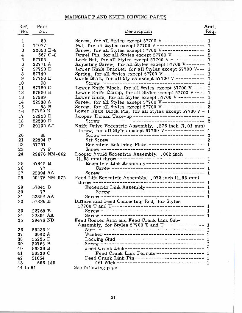
MAINSILAFT AND KNIFE DRIViNG PARTS
I.L Pail, Amt,No No. Description Req.
1. 89 Screw, for all Styles except 57700 V 12 14077 Nut, for all Styles except 57700 V 13 22653 13-8 Screw, for all Styles except 57700 V 24 667 C—B J)owcl Pin, for all Styles except 57700 V 25 57795 Lock Nut, for all Styles except 57700 V 16 22771 A Adjusting Screw, for all Styles except 57700 V 17 57750 I) Lower Knife Bracket, for all Styles except 57700 V 18 57740 Spring, for all Styles except 57700 V 19 57750 E Guide Shaft, for all Styles except 57700 V 1
10 98 Screw 111 57750 C Lower Knife Block, for all Styles except 57700 V ———— 112 57950 13 Lower Knife Clamp, for all Styles except 57700 V--— 113 57949 Lower Knife, for all Styles except 57700 V 114 22588 A Screw, for all Styles except 57700 V 115 88 B Screw, for all Styles except 57700 V 216 57750 II Lower Knile Block Pin, for all Styles except 57700 V 117 52923 D Looper Thread Take—up 118 22580 D Screw 219 29132 AJ Knife Drive Eccentric Assembly, .276 inch (7.01 mm)
throw, for all Styles except 57700 V 120 88 Screw 221 22894 P Set Screw 222 57751 Eccentric Retaining Plate 123 77 P Screw 224 29476 NM-062 Looper Avoid Eccentric Assembly, .062 inch
(1.58 mm) throw 125 57845 B Eccentric Link Assembly 126 77 Screw 127 22894 AA Screw 128 29476 NM-072 Feed Lift Eccentric Assembly, . 072 inch (1.83 mm)
throw 129 57845 B Eccentric Link Assembly 130 77 Screw 131 22894 AA Screw 132 57836 E Differential Feed Connecting Rod, for Styles
57700 T and U 133 22768 B Screw 134 22894 AA Screw 135 29476 ND Feed Rocker Arm and Feed Crank Link Sub
Assembly, for Styles 57700 T and U 136 55235 E Nut 137 6042 A Washer 138 55235 D Locking Stud 139 22763 13 Screw 140 56336 B Feed Crank Link 141 56336 C Feed Crank Link Ferrule 142 51054 Feed Crank Link Pin 143 666-149 Oil Wick 144 to 81 See following page
31

B1
13
5
çØø
162
sff; L,‘
15
CI)
-2126 18
7 19-2in.
(Ne1}
4850
________
\\\\
— /_—-— 6
__
TO1iQU1 TO I . I 1355 rn. lbs.(6 1rn / kL)
74>
IL,‘432

MAINSI-IAFT AND KNIVE DRiVING PARTS
Ref. PartNo. — No.
1 to 4344 22525 A45 56322 C46 5633647 22798 C48 22543 A49 660—269 B50 56336 D51 39543 N52 57722 B53 56322 B54 22891 B55 51236 A56 2280157 87U58 57779 A59 7904860 57773 A61 57736 A62 2276463 6042 A64 55235 E65 5778566 22567 B67 57750 B68 22782 A69 57750 F70 7771 57773 B72 5777373 22852 A74 667 C-1075 39147 D76 8877 5773578 22565 C79 57750 G
80 57770 A81 21657 E82 269
Description
See preceding pageScrew1V[ain Shaft Head PlateFeed Crank Stud, marked NA”
ScrewStitch Regulating ScrewQuad RingFeed Crank Stud InsertThrust WasherMain Shaft, for Styles 57700 T and U
GasketOil Flow Regulating Screw
Link Pin, for all Styles except 57700 VScrew, for take-upScrew, for all Styles except 57700 VChip Guard, upper, for all Styles except 57700 V—--Screw, for all Styles except 57700 VKnife Driving Lever, for all Styles except 57700 V --
Locking StudSpot ScrewWasherNut
Knife Drive Shaft, for all Styles except 57700 VScrew, for all Styles except 57700 VEccentric Nut, for all Styles except 57700 VScrew, for all Styles except 57700 VKnife Drive Link, for all Styles except 57700 V
ScrewKnife Bracket, for all Styles except 57700 V
BushingScrew, for all Styles except 57700 VDowel Pin, for all Styles except 57700 VCollar, for all Styles except 57700 V
ScrewStop Collar, for all Styles except 57700 V
ScrewLower Knife Bearing Block, for 57750 C, for all
Styles except 57700 VUpper Knife, for all Styles except 57700 VWasherNut, left thread
Amt.Req.
41111112111112111111111111112221211
1111
33

3?
34

No.
2
456789
101 112131415161718192021222324252627282929A30313233343536373839404142434445464748495051525354
No.
57636 C57006—040570:36 A56334 11571136 I)
6042 A55235 135733557336 C5783657034 356335 D
982259757834 0’22651 C11—457834 1.)57834 C22637 P—2457837 D5785357834 C2259322593
52953 A22653 B—1451235 G52825 F52825 B52925 D22635 E—24C L2 157834 AC L2 1
Cull sf5 [115 57700 ‘1 and Ii oNUS
I)! II’ IlIillN’.FIAL .l.’E11I) MIICI IASIISIVI PA I{TS
I )ese i pti on
1)1 fl’viejItia[ Iced Drive Flockei ShaCi: IStretch I)iUercntial Food Iiockei’, .040 inch (1.02 mm) throw
---- 1Ilushing 1Hushing 2
I oeking Stud 1VVn slier 1Nut 1iVIain Iced liockei Shaft, lower 1Main Feed F1ockei 1
I3ushing 2Main Feed Itocicer Shaft, upper 1Collar, for lower main feed rocker driving shaft 2
Screw 2Set Screw 1iSlam Feed Bar 1
Screw 1Hushing 2l3ushing 2Feed Dog Height Adjusting Screw 1
Differential Feed Bar Guide Plate 1Feed Dog Holder Support 1Oil Wick Retainer 1Screw 2Screw, for main feed dog 2lVlain Feed Dog (See Page 41) 1Feed Dog holder 1Screw 1Washer 1Rear Needle Guard, for Style 57700 T 1Rear Needle Guard, for Style 57700 U 1Needle Guard Holder 1Screw 1Oil Wick 2Differential Feed Bar 1
Oil Wick 1Differential Feed Dog (See Page 41) 1Screw 1Link Pin 1Driving Link Guide 1
Screw 2Differential Driving Link Collar 1
Screw 1Intermittent Differential Feed Bar Driving Link 1Screw, for differential control lever and link 1Differential Feed Control Lever Link 1Differential Feed Control Lever 1Differential Feed Control Lever l3ushing 1Nut 2Washer 1Differential Feed Control Indicator 1Lock Screw 1Nut 1Washer 1Nut 2Differential Feed Link Sleeve, left 1Sliding Block, marked NJ; . 2540 inch (6.45 nun) wide 1Sliding Block, marked ‘TP°, .2545 inch(6.46 mm) wide 1Sliding Block, marked ‘l3, .2550 inch (6.48 mm) wide 1Differential Feed Link Sleeve, right 1Differential Feed Regulating Screw 1Thrust Washer, for feed bar 2Washer 1Tru-Arc fling 1
9051236 A.57837 E2274357837 F22738 B57835 B22758 B57835 D57835 C57837 C9937
69 H57835 E22874 K12934 A80265
9075783757836 F—4057836 F-45571336 l’—50
56 57837 A57 22868 1358 61341 J59 4139160 660—438
35
B
9
4)18
21A\
36
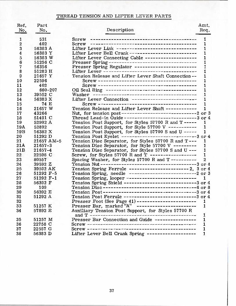
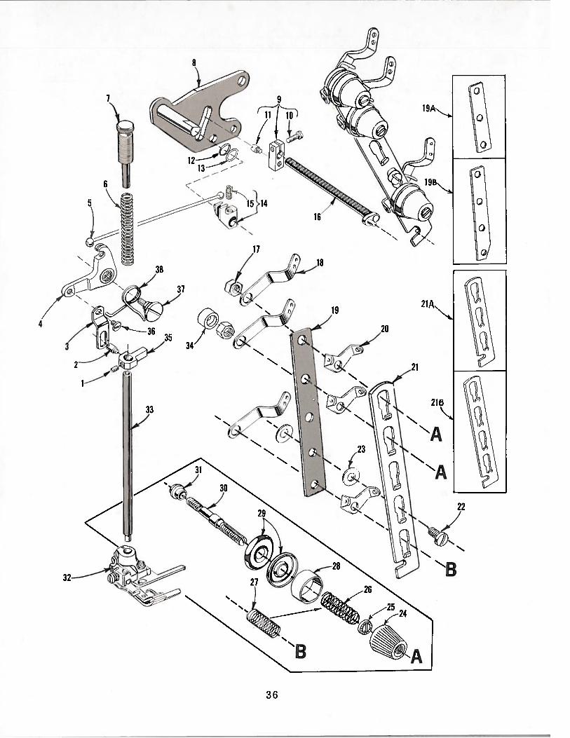
THREAD TENSION ANT) LIFTIIIIt LEVER PA.I{TS
Ref. Part Amt,No. No. Req.
1 12 1C)
4 15 16 17 18 19 1
10 111 112 113 114 115 116 117 or318 or419 119A 119B 120 or421 121A 121B 122 123 224 or425 or426 or327 128 or429 or830 or431 or432 133 51257 K 134 57892 E
11111
Des cription
531 Screw402 Screw
56383 A Lifter Lever Link56383 Y Lifter Lever Bell Crank56383 W Lifter Lever Connecting Cable51256 C Presser Spring56356 Presser Spring Regulator51283 I-I Lifter Lever21657 Y Tension Release and Lifter Lever Shaft Connection--22596 Screw
402 Screw660-207 Oil Seal Ring
39552 C Washer56383 X Lifter Lever Connection
74 E Screw21657 W Tension Release and Lifter Lever Shaft43266 Nut, for tension post 251491 C Thread Lead-in Guide 352992 A Tension Post Support, for Styles 57700 R and T52892 Tension Post Support, for Style 57700 V56382 X Tension Post Support, for Styles 57700 S and U51292 D Tension Post Eyelet 321657 AM-5 Tension Disc Separator, for Styles 57700 H and T--21657-3 Tension Disc Separator, for Style 57700 V21657-4 Tension Disc Separator, for Styles 57700 S and U22 598 C Screw, for Styles 57700 H and T80557 Spacing Washer, for Styles 57700 R and T39592 Z Tension Nut 339592 AK Tension Spring Ferrule 2, 351292 F-5 Tension Spring, needle 251292 F-i Tension Spring, looper56392 F Tension Spring Shield 3
109 Tension Disc 656392 E Tension Post 351292 A Tension Post Ferrule 3
Presser Foot (See Page 41)Presser Bar, marked “A’TAuxiliary Tension Post Support, for Styles 57700 H
and T35 51257 M Presser Bar Connection and Guide36 22758 C Screw37 22557 G Screw38 56383 D Lifter Lever Bell Crank Spring
37


CLOTH PLATES, COVE FS, OIL SHIELDS AND 1’OLDE l
IbI. Part Amt.No. No. Des cripti.on
1 57701 C Cloth Plate, ror Style 57700 V 12 57701 A Cloth Plate, for Styles 57700 P and S 13 25 C Screw, for No. 23405 W 24 23405 W Folder, for Style 57700 V 15 22726 Screw 26 12957 E Spring Washer 27 39152 U—6 Shim, for Style 57700 V 28 57701 P Cloth Plate, for Styles 57700 T and U 19 22839 C Screw 2
10 57802 A Cloth Plate Cover, for Styles 57700 R, S, T and U - 111 51282 AJ Hinged Oil Shield, front, for Style 57700 V 112 52978 0 I-Tinge Pin 113 51282 AK Spring 214 25 S Screw, for No. 51282 AJ 215 22848 Screw 316 20 Washer 317 51282 Al-I Oil Shield, end and back 118 22526 D Screw, for all Styles except 57700 V 119 22526 C Screw 220 22839 E Screw 121 56381—219 Cloth Plate Cover, for Style 57700 V 122 22845 B Pivot Screw 123 22760 A Screw 324 35772 I-I Washer 325 51281 AC Cloth Plate Cover Spring 1
39

C
C.,
Cii
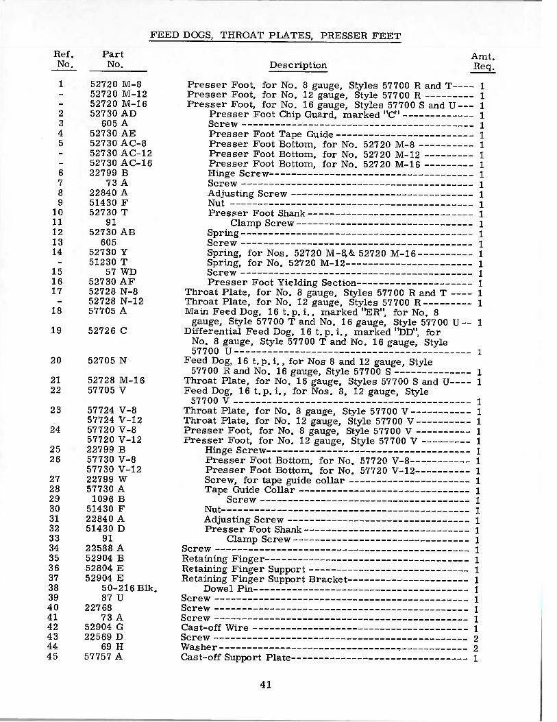
F’IED DoGS, T1[ROAT PLATES, PRESSER FEET
Amt.Description Req.
Presser Foot, for No. H gauge, Styles 57700 H and T———— 1Presser Foot, for No. 12 gauge, Style 57700 H 1Presser Foot, for No. 16 gauge, Styles 57700 S and U--- 1
Presser Foot Chip Guard, marked C1 1Screw 1Presser Foot Tape Guide 1Presser Foot Bottom, for No. 52720 1VI-8 1Presser Foot Bottom, for No. 52720 M—12 1Presser Foot Bottom, for No. 52720 M-16 11-linge Screw 1Screw 1Adjusting Screw 1Nut 1Presser Foot Shank 1
Clamp Screw 1Spring 1Screw 1Spring, for Nos. 52720 M—8,& 52720 M—l6 1Spring, for No. 52720 1VI-12 1Screw 1Presser Foot Yielding Section 1
Throat Plate, for No. 8 gauge, Styles 57700 Ft and T ---- 1Throat Plate, for No. 12 gauge, Styles 57700 Ft 1Main Feed Dog, 16 t.p.i,, marked TTER”, for No. 8
gauge, Style 57700 T and No. 16 gauge, Style 57700 U-- 1Differential Feed Dog, 16 t.p.i., marked MDDT1, for
No. 8 gauge, Style 57700 T and No. 16 gauge, Style57700 U 1
Feed Dog, 16 t.p.i., for Nos 8 and 12 gauge, Style57700 r and No. 16 gauge, Style 57700 S 1
Throat Plate, for No, 16 gauge, Styles 57700 S and U---- 1Feed Dog, 16 t.p. i,, for Nos. 8, 12 gauge, Style
57700 V 1Throat Plate, for No. 8 gauge, Style 57700 V 1Throat Plate, for No. 12 gauge, Style 57700 V 1Presser Foot, for No, 8 gauge, Style 57700 V 1Presser Foot, for No. 12 gauge, Style 57700 V 1
Hinge Screw 1Presser Foot Bottom, for No. 57720 V-8 1Presser Foot Bottom, for No. 57720 V-12 1Screw, for tape guide collar 1Tape Guide Collar 1
Screw 1Nut 1Adjusting Screw 1Presser Foot Shank 1
Clamp Screw 1Screw 1Retaining Finger 1Retaining Finger Support 1Retaining Finger Support Bracket 1
Dowel Pin 1Screw 1Screw 1Screw 1Cast-off Wire 1Screw 2Washer 2Cast-off Support Plate 1
I ii’tNh). No.
1 52720 U—B— 52720 M—12— 52720 M—162 52730 AD3 6051\4 52730 AE5 52730 AC—8— 52730 AC—l2— 52730 AC—l66 22799 B7 73A8 22840 A9 51430 F
10 52730 T11 9112 52730 AB13 60514 52730 Y
— 51230 T15 57WD16 52730AF17 52728 N—8
— 52728 N—1218 57705 A
19 52726 C
20 52705 N
21 52728 M—1622 57705 V
23 57724 V—857724 V—12
24 57720 V—857720 V—12
25 22799 B26 57730 V—8
57730 V—1227 22799 W28 57730 A29 1096 B30 51430 F31 22840 A32 51430 D33 9134 22588 A35 52904 B36 52804 E37 52904 E38 50—2l6Blk.39 87U40 2276841 73A42 52904 G43 22569 D44 69H45 57757 A
41

C-,
‘3

T.IIIEAIJ STAND, ACCESSORIES AND ELASTiC REEL
K(’I, Pa it.No No, Description Req.
1 21101 I I— fhread Stand, complete 12 21 101 V Pad, for thread cone 43 21114 W Spool Pin 44 258 A Nut 45 21114 Spooi Seat Disc 46 652—16 Washer 47 258 A Nut 48 21114 A Thread Stand Base 19 22651 CD-4 Screw 1
10 21114 U Lead Eyelet Ball Split Socket 211 652—16 Washer 112 21104 II Nut 113 21104 B-24 Thread Stand Rod 114 21114 D-4 Spool Seat Support I15 22651 CD—5 Screw 216 21114 fi-4 Eyelet Support 117 22651 CD—4 Screw 118 21114 T Lead Eyelet Socket Ball 119 22651 CD-4 Screw 120 22810 Screw 121 21114 S-4 Lead Eyelet 122 201 C Thumbscrew 223 21177 B Binding Guide Collar 224 21104 B-14 Elastic Reel Rod 125 21173 A Vertical Rod Connection 126 22650 CD-4 Set Screw 227 21104 B-24 Elastic Reel Support Rod 128 21114 A Elastic Holder Base 129 22651 CD—4 Screw 130 660-264 HIl Hook 231 421 D-34 Treadle Chain, 34 inches (863. 60 mm) long 132 21388 Wrench, 3/8 inch (9,52 mm) open end 133 660-240 Thread Tweezers 134 21201 Screwdriver, 9/64 inch (3, 58 mm) round blade, length
overall 7 5/8 inches (177.8 mm) 135 51295 B Isolato 336 51295 A Isolator 1
- SC303 Screw, for thread stand and elastic holder base(not shown) 6
43
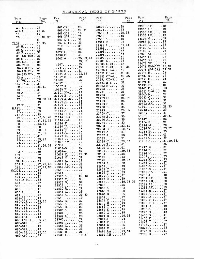
N U VI H 111 (‘ A L I N BE \ 1)8’ I’ A Ii ‘I’ S
I ‘a rLNo.
WI—S.\\:( )._‘318.20,
(11.21.23,3525 I) .1925 c: .3925S 3927—4 35 ilk. .2328 H 2339—141 2540—C193 . . . .2550—216 ilk. .41.50—458 111k. .2750—895 Elk 2152A 1957 Wi) 41
(10—67 11 , , . .2769 H 35,4173 2773A 4174 H 3777 23, 29, 31,
3377P 31
i-TA81 2387 19
487.] 2587 U 27, 33,41
88 27, 31, 3388 B 23, 3188D 1989 23, 3190 21,3591 4195 19,2396 2798 27,29,31,
3598A 19
109 37158 II 19201 C 43
258 A 27,29.43269 27, 29, 33
SC303 43357 19402 37421 D-34 43531 37539 19605 41605 A 41627 25652—16 43660—202 23,25660—207 37660—215 23660—221 21660—240 43660—264 43660—269 13. . . . 20, 33660—310 27660—313 19660—342 19660—438 29, 35660—455 21
6615—123 23666—N 9 29, 31666—211 19666—259 21667 C—B 31667 C—b. . . . 33719 27907 35
1022 L 251096 13 416042 A 25,29
33, 357947 199937 35
11635 13 2112934 A 23, 3512957 H 3912982 2514077 3115037 A 2515465 P 2721101 1-1—4 4321104 13—14. . . .4321104 13—24. . . .4321104 I-I 4321104 V 4321114 4321114 A 4321114 13—4 4321114 1-1—4 4321114 S-4 4321114 T 4321114 U 4321114 W 4321173 A 4321177 B 4321201 4321375 AV 1921388 4321657—3 3721657—4 3721657 E 29, 3321657 W 3721657 X 2121657 V 3721657 AM—5 . . . 3722513 1922524 1922525 A 29, 3322526 C 3922526 B 3922528 2922539 R 2122541 C 2122543 A 29, 3322548 1922557 G 37225.59 A 2322559 G 2322560 A 2522562 2522562 A 2322563 2722564 2322565 C 3322567 13 3322569 2122569 C 19,41
I ‘ir’INo.
22570 A 252257I 2322581) I) 29. 31225115 11)22585 A .1922587 12 23225811 A 31,4122591 2322593 3522596 3722597 3522598 C 3722635 12—24 . . . 3522637 I’—24 . . .29, 3522650 CI)—4 4322651 CH—4 29, 3522651 CI)—4. . . .29,4322651 CI)—5. . . .4322653 H—B 3122653 13—14 . . . . 3522703 2522711 2122726 3922729 C 25,2722733 2522733 E 2122738 13 3.522743 2.5, 3522758 C 372275812 3522760 A 3922764 3322768 23.4122768 B 19,3122771 A 3122782 A 3322793 2122798 C 29.3322799 B 4122799 W 4122801 29, 3322804 2522810 4322829 19.2722834 A 2922839 1922839 C22839 E.22840 A.22845 B.2284822852...22852 A.22863 C.22868 B.2287422874 K 3522875 H 2922882 C 2722889 B 2522889 G 1922891 B 29, 3322894 J 2322394 P 3122894 W 2522894 X 2322894 AA 29, 3122894 AB 23
I ‘a ri
No,
23306 Al’ 1923306 A’f 1923306 AU 1923306 AV 1923405 W 3929066 Ii 2329105 Al 2329132 Al 3129192 Z 2729348 AC 2329476 LU 2329476 11,1 2929476 NI) 3129476 NIV[—062 29, 3129476 N5I—072 .29, 3133174 B 2735731 A 1935761 13 2135772 11 3935897 By 2139147 D 3339152 U—6 3939543 N 2939552 C 3739592 Z 3739592 ATK 3741391 29, 3543242 P 2543266 3751054 29, 3151147 23:51154 B 2151216 lvi 23.51216 N 23,2751216 P 2351230 T 4151235 G 3551236 A 27, 29, 33,
3551242 M 2751244 L 2751244 N 2751247 2351254 K 2352256 C 3751257 K 3751257 M 3751257 AA 2151280 J 1951281 AC 3951282 All 3951282 AJ 951282 AK 3951283 H 3751292 A 3751292 13 751292 F—i 3751292 F—5 3751294 R 1951295 A 4351295 13 4351430 13 4151430 F 4151491 C 3751745 2752336 A 2352705 N 4152708 B 27
I ‘a a’ I ‘a r’i INo. No
23.23, 27
27.19, 21, 27,
39
31
3939413919,21,392533293527
44

IJUNIi’I5ICAT INI)I\ 01’ i’AI3TS
52717 P—12. . .2352720 \I—3. . . .41:2720 ftI—12 .4152720 U—i (5 . .4152726 C 4152723 M—i 6 . .4152728 SJ—B. . . .4152728 C—i2. . .4152730 T 4152730 Y 41:2730 All .. .412730 AC—B . .41
52730 AC—12, .4152730 AC—16, .4152730 AT) .. . .4152730 AL . . . .4152730 AL . . . .4152750 2552750 iS 152776 P 2552776 V 2552776 W 2552777 P 2552777 R 2552777 S 2552717 T 2552777 U 2552777 V 2552777 W 2552777 X 2552777 Y 2552777 Z 2552777 AA . . . .2552777 AC . . . .2552777 AE . . . .2552778 D 2552778 F 2552778 N 2552778 P 2552778 W 2552782 C 1952804 E 4152817—16 2352817 E—8. . . .2352818—8 2352824 CS 2352825 Ii 3552825 D 2752825 F 5
52892 3752904 13 4152904 E 4152904 G 4152923 D 29, 3152925 D 3552942 A 2352942 II 2752942 W 2152942 Y 152943 L 352951 C 2552953 A 3552958 13 1952978 0 952992 A 3753678 555235 D 25, 29, 31
No,
55235 i 25, 29, 31,3, :s
56344 B 2756354 C 2156354 D 2356356 3756381—219 956382 1956382 B 2156382 C 2156382 D 1956382 E 1956382 G 1956382 H 1956382 J 1956382 K 1956382 L 1956382 M 2156382 N 1956382 X 3756382 Y 1956382 AA . . . . 1956382 AC . . .2156383 A 3756383 D 3756383 W 3756383 X 3756383 Y 3756390 2156390 H 2156390 B 2156390 G 2156391 1956392 B 3756392 F 3756393 C 1956393 D 1956393 J 2756393 K 2756393 L 2156393 P 21
56393 Q I56:393 ‘ 2156393 \V 2156393 AC 11)56394 A 156:394 II 2156394 C 2156453 23564:3 A 2356470 1956953 2356958 A 2357701 A 3937701 II 3957701 c: 3957705 A 4157705 V 4157713 2757720 V—B 4157720 V—12. ..4157722 A 2957722 13 3357722 E 2957724 V—B 4157724 V—12. . . .4157725 2957725 B 2757730 A 4157730 V—8 4157730 V—12. . . .4157735 3357736A 3357740 3157741 2557741 A 2557744 2757744 A 2757750 A 2157750 B 3357750 C 3157750 B 3157750 B 3157750 F 3357750 CI 3357750 H57751 157757 A 4157770 1957770 A 3357773 3:357773 A 3357773 B57776 557776 A 2557777 25
Afl’?’ H57777 C57777 E 2557777 F 2557777 (5 25
i57777 J 2557777 K 2557778 25
A37778 13 2557779 21
I ‘L ri.NJ0.
57779 A -I57733 2557735 .3
3157302 A 3957306—04057321 23
A57834 13 3557334 C 3557334 D 3557334 p 3557834 G 29, 3557835 3557835 B 3557335 C 3557835 U 3557835 E 3.57336 3557836 A 3557836 3 2157336 C 3557836 U 3557836 B 3157836 F—40 3557836 F—45 3557836 F—5057836 C 3557837 3557837 A 3557837 C 3557837 D 3557837 E 557837 F 3557840 2757841 2757842 : 157845 B 29,3157846 B 2757853 3557880 1957882 C 157882 P 1957882 0 2157892 B :3757949 3157950 11 3159348 C 2561256 G 161321 T 361341 J 29,3561434 0 2962293 A 2363494 13 2163494 F 163494 (5 2163494 K 2179048 3380265 3580557 37
‘‘INo,
I :, I ‘: ri I U
No. No, No.I ‘15’
NJo.
55241 0.561905631 656316 C,56:321 ii,56322 3.56322 C.56334 13.56334 L.56334 NJ.56334 1$.56335 I).56335 (5.56335 L.5633656336 IS.56336 C.:36336 D.56341 E,56341 F....56341 CI.56341 NI5634256342 1356343 C.56343 1).56343 B.
27.21
23..23.23.29, 33.29, 33.29.29.29
35.29, 31
29.29.29, 33.29, 31.29, 31.29, 33
27.25,27
272727
.23
.23
.23
.23
45
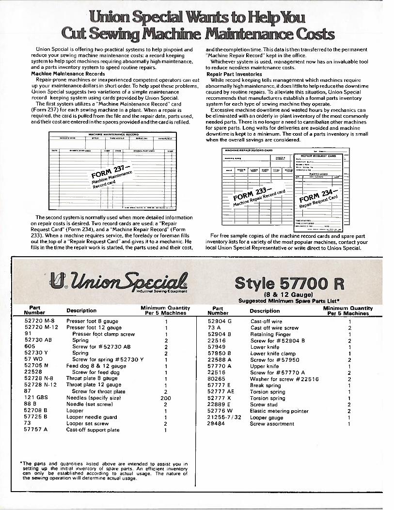
Union Special Wants to HelpibuCut Sewing Machine Maintenance Costs
For free sample copies of the machine record cards and spare partinventory lists for a variety of the most popular machines, contact yourlocal Union Special Representative or write direct to Union Special.
Style 57700 R(8 & 12 Gauge)
Suggested Minimum Spare Parts List*
Part Minimum Quantity Part Minimum QuantityNumber Description Per 5 Machines Number Description Per 5 Machines
52 720 M-8 Presser foot 8 gauge 1 52904 G Cast-off wire 152720 M-1 2 Presser foot 12 gauge 1 73 A Cast off wire screw 291 Presser foot clamp screw 1 52904 B Retaining Finger 152730 AB Spring 2 22516 Screw for #52904 B 2605 Screw for #52730 AS 2 57949 Lower knife 152730 Y Spring 2 57950 B Lower knife clamp 157 WD Screw for spring #52730 Y 1 22588 A Screw for #57950 252705 N Feed dog 8 & 12 gauge 1 57770 A Upper knife 122528 Screw for feed dog 1 22516 Screw for #57770 A 252728 N-8 Throat plate 8 gauge 1 80265 Washer for screw #225 16 252728 N-12 Throat plate 12 gauge 1 57777 E Break spring 187 Screw for throat plate 2 52777 AE Torsion spring 1121 GBS Needles (specify size) 200 52777 X Torsion spring 188 B Needle (set screw) 2 22889 E Screw stud 252708 B Looper 1 52776 W Elastic metering pointer 257725 B Looper needle guard 1 21255-7 / 32 Looper gauge 173 Looper set screw 2 29484 Screw assortment 157757 A Cast-off support plate 1
The parts and quantities listed above arc intended to assist you insetting up the inital inventory of spare parts An efficient inventorycan only be establshed according to actual usage. The nature ofthe sewing operation will determine actual usage.
and thecoinplefion time. Thisduta isftien fiansferred fo the piniaiienf
Machine Repair Record kepf in ffie office.Whichever system is used, niaiiaqeinent now has an iiivalu,ihli’ tool
to reduce needless maintenance costs.Repair Part Inventories
While record keepinq tells niaiiageinent wfticfi machines t equii t’
abnormally high niaintenaiicc, it does little to help reduce the dowot inncai.ised by routine repairs. To alleviate this situation, Union Sin’i i,ilrecommends that manufacturers establish a formal parts ioveiifoi ysystem for each fype of sewing machine they operafe.
Excessive machine downfime and wasted hours by mechanics canbe eliminated with an orderly in-plant inventory of the most commonlyneeded parts. There is no longer a need to cannibalize other machinesfor spare parts. Long waits for deliveries are avoided and machinedowntime is kept to a minimum. The cost of a parts inventory is smallwhen the overall savings are considered.
l.lniun Special is often i(l fwo prtctical systm.’mmis to help puipoint andinduce yoni sewing niacliine maintenance costs: a record keepingsystem Ii) help spot ui,tcliiues requiring abnormally high mamiitenamice,and a parts iveutoi y systeimi to speed routine repairs.Machine Maintetiance RecordsRe1aim-proue iiiiclunes or iriexpei i enced competent operators can eat
Uli vow maintenance dollars in short omder, To help spot these problems,(liiinn Special suqgm’sfs two variations of a simple mainfenanceI iS uid keeping system using cards piovided by Union Special.
The first system utilizes a “Machine Maintenance Record cardIlni ti 237) for each sewing machine iii a plant. When a repair isinquired, the card is pulled from the file and the repair date, parts used,and their cost are entered in the spaces provided and the card is refiled.
.1
31
The second system is normally used when more detailed informationon repair costs is desired. Two record cards are used: a “RepairRequest Card” (Form 234), and a “Machine Repair Record” (Form233), When a machine requires service, the [orelady or foreman fillsout the top of a “Repair Request Card’ and gives it to a mechanic. Hefills in the time the repair work is started, the parts used and their cost,
- I.. -

uNION SPECIALCORPORATION
iii authoritative information on the most efficient types of equipment for making virtually anylie Pine sewed article is available from Union Special
Sales Promotion Department. Among the many interosting, illustrated bulletins that are available withoutoN gal ion are the following: HERE ARE HELPFUL
BULLETINS and CATALOGSTO HELP YOU SOLVESEWING PROBLEMS
No. 240, ‘Men’s, Women’s, Children’s Footwear”
No. 249, ‘Rainwear”
No. 250, “Men’s Dress Shirts’
No. 251, “Service Shirts and Pants”
No. 252, “Men’s Shorts and Pajamas”
No. 253, “Overalls, Coveralls, and Dungarees”
No. 254, “Men’s Knit Underwear”
No. 256, “Knit Outerwear”
No. 259, “Men’s Sports Shirts”
No. 260, “Work Gloves”
No. 262, “Cotton, Burlap, Jute, and MultiwallBags”
Paper
No. 263, “Men’s Clothing”
No. 264, “Men’s Women’s, Children’s Jackets”
No. 265, “Women’s Wear”
No. 266, “Women’s Wear And High Fashion”
No. 267, “Corsets, Girdles, Brassieres”
No. 268, “Children’s Wear”
No. 269, “Mattresses, Slip Covers, FurnitureUpholstery”
No. 271, “Awnings, Canopies, Tents, Tarps”
No. 273, “Curtains & Drapes”
No. 610, “Klipp-it”
No. 710, “MCS ForMation Unit”
No. 730, “MCS Automatic Dual Underfront ShirtHemmer”
No. 740, “MCS Automatic Rib-Knit Cuff Machine”
No. 750, “Fusing Presses”
No. 1100, “Lewis Blindstitch, Chainstitch, Lock-stitch, Machines”
No. 1105, “Button Sewers—Ticket Tackers”
“Columbia Blindstitch, Saddle Stitch, and Tie Closing Machines”
No. 1500, “Alteration Department Machines”
UFINEST QUALITY
I,’

WORLD’S FINEST QUALITY
* INDUSTRIAL SEWING MACHINES
UNION SPECIAL maintains sales and servicefacilities throughout the world. These offices willaid you in the selection of the right sewingequipment for your particular operation. UnionSpecial representatives and service men are factory trained and are able to serve your needspromptly and efficiently. Whatever your location, there is a Union Special Representative toserve you. Check with him today.
ATLANTA, GA. MONTREAL, CANADA
BOSTON, MASS. TORONTO, CANADA
CHICAGO, ILL. BRUSSELS, BELGIUM
DALLAS, TEXAS LEICESTER, ENGLAND
LOS ANGELES, CAL. LONDON, ENGLAND
NEW YORK, N. Y. PARIS, FRANCE
PHILADELPHIA, PA. STUTTGART, GERMANY
Representatives and distributors in all importantindustrial cities throughout the world.
UNION SPECIAL CORPORATION400 N. FRANKLIN ST., CHICAGO, ILL. 60610