unified modeling language i. · unified modeling language i. ... outline software engineering...
TRANSCRIPT

Unified Modeling Language I.
Software engineering
Szoftvertechnológia
Dr. Balázs Simon
BME, IIT

Outline
Software engineering
Modeling
Unified Modeling Language (UML)
UML Diagrams: Use Case Diagram
Activity Diagram
Component Diagram
Deployment Diagram
2Dr. Balázs Simon, BME, IIT

Software engineering
Dr. Balázs Simon, BME, IIT 3

Software engineering
Software is everywhere: operating systems (Windows, Unix, Android, iOS, etc.) office tools (Word, Excel, Chrome, Firefox, Photoshop, etc.) entertainment (YouTube, Facebook, etc.) everyday tools (hairdryer, washing machine, etc.) safety critical systems (cars, airplanes, rockets, nuclear power
plants, robotic surgery, etc.)
“Software engineering is the systematic application of scientific and technological knowledge, methods, and experience to the design, implementation, testing, and documentation of software”Systems and software engineering - Vocabulary, ISO/IEC/IEEE std 24765:2010(E), 2010.
Dr. Balázs Simon, BME, IIT 4

Why is software engineering hard?
Software can be very large Windows 10: ~50 million lines of code the complete Google software codebase in 2015: ~2 billion lines of
code, 45000 changes a day large software cannot be written by a single person
The software industry is young (~50 years old) we have had roads, bridges and buildings for thousands of years we have widely accepted standards and prebuilt parts in the
construction industry the software industry doesn’t have the range of prebuilt standard
components that other industries have
Most of the software is custom built since there are no prebuilt components for everything constructing the software is a creative process most parts of a software are new and unproven, hence they must be
tested but the inherent complexity of the software makes it hard to test
Dr. Balázs Simon, BME, IIT 5

Why is software engineering hard?
Custom built software is ordered by the users of the software, who don’t know what they want users do not have the expertise of a software engineer, they can’t
specify exactly what they want users usually don’t know what they really want until they can see it
and try it out the time and money resources assigned to develop the software can
easily run out due to the changing requirements estimating the time and money for a software development project is
an art, not a science software engineers must prepare for changing requirements in
advance
Software engineer ≠ programmer software engineers design the software before they start coding in the design they have to take into account the needs of the users
and the changing requirements software engineers must know which algorithm to apply and when experienced software engineers do things quicker and better, with less
code and with fewer defects
Dr. Balázs Simon, BME, IIT 6

Software development processes
Software development consists of the following processes: Requirements analysis and specification: finding out what the user wants Design: designing the architecture, components and behavior of the
software Implementation: developing and integrating the components Testing: systematic discovery and debugging of defects Delivery: installing the software for end users, education of users Maintenance: keeping the software running, fixing bugs
These are not steps! These are processes that follow the development of the software throughout its entire life cycle!
Software is usually developed in multiple iterations all of the above processes can be involved in each iteration, usually in the
following order:
each process may have a different importance depending on the iteration, e.g. requirements analysis is more important in the first iteration, while maintenance is more important in the later iterations
Dr. Balázs Simon, BME, IIT 7
Requirements Design Implementation Testing Delivery Maintenance

Unified Modeling Language (UML)
Dr. Balázs Simon, BME, IIT 8

Modeling
A model is a simplified reflection of reality
A good model emphasizes essential details and omits irrelevant ones
Example: Budapest underground map essential details:
names of stops
order of stops
transfer points
irrelevant details: streets
distances between stops
color of the tunnel
Dr. Balázs Simon, BME, IIT 9

Other modeling examples
Model of the solar system: essential details: mass, speed and distance of planets
irrelevant details: e.g. atoms the planets are built of
Wind tunnel model of a plane: essential details: shape, aerodynamics
irrelevant details: e.g. number of seats, food served, pilot
Ticket reservation model of a plane: essential details: number of seats, food served
irrelevant details: e.g. shape, aerodynamics, pilot
Dr. Balázs Simon, BME, IIT 10

Views
The essential and irrelevant details depend on: what the model is used for who will read the model
The more information the model has to cover the more complex it becomes
Sometimes the same model is used for multiple purposes and viewed by different target audiences we can create many views of the same model each view shows only the relevant details for the given purpose and to the
given target audience
Example: same model with different views:
Dr. Balázs Simon, BME, IIT 11

UML
Unified Modeling Language
Standard for modeling software systems standardized by Object Management Group (OMG)
The UML standard defines multiple diagram types: each diagram provides one view of a model of a system
The UML standard specifies: syntax: how the elements of a diagram (view) look like
semantics: what the model shown in a diagram means
Both the syntax and the semantics are important
The semantics shown in different diagrams must be consistent with each other, otherwise, the underlying model is meaningless and useless
Dr. Balázs Simon, BME, IIT 12
UML semantics
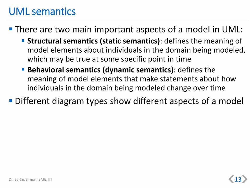
There are two main important aspects of a model in UML: Structural semantics (static semantics): defines the meaning of
model elements about individuals in the domain being modeled, which may be true at some specific point in time
Behavioral semantics (dynamic semantics): defines the meaning of model elements that make statements about how individuals in the domain being modeled change over time
Different diagram types show different aspects of a model
Dr. Balázs Simon, BME, IIT 13

UML diagram types
Dr. Balázs Simon, BME, IIT 14
Use case diagram
Deployment diagram
Component diagram
Class diagram Package diagram
Object diagramComposite
structure diagramProfile diagram
Activity diagram Sequence diagramCommunication
diagram
State diagram Timing diagramInteraction
overview diagram
Structural UML diagrams:
Behavioral UML diagrams:

Use Case Diagram
Dr. Balázs Simon, BME, IIT 15

Use Case Diagram
Captures the functional requirements of the system what the system is supposed to do and how the system is used
models the users and the scope of the system
simple enough for stakeholders to understand it
Example: Pac-Man game
Dr. Balázs Simon, BME, IIT 16
Player
Control Pac-Man
View Maze
Requirements Design Implementation Testing Delivery Maintenance

Player
Control Pac-Man
View Maze
Use Case Diagram
Actor: a role of a user that interacts with the system can be a person or an outside system (a physical user can interact with the system in multiple roles)
Use case: represents a dialog between users and the system from the users’ point of view a specific sequence of actions and interactions between the actors and the
system
Association: connects an actor with a use case he/she/it is involved in
Dr. Balázs Simon, BME, IIT 17
ActorUse case
Association

Use case description example: Buy item
Dr. Balázs Simon, BME, IIT 18
Use case: Buy item
Actors: Customer, Cashier
Main Success Scenario: 1. The Customer picks the item 2. The Customer hands the item to the Cashier 3. The Cashier records the item 4. The Cashier asks for money from the Customer 5. The Customer pays the amount to the Cashier 6. The Cashier gives the item and the receipt to the Customer
Alternative 5.A: 5.A.1. The Customer has not enough money 5.A.2. The Customer leaves empty handed
Customer
Buy item
Cashier

Use Case Diagram: Relationships
Between an actor and a use case: Association:
connects an actor with a use case he/she/it is involved in
Between actors: Generalization:
the special actor is a kind of general actor the special actor can do all the use cases the general actor can
Between use cases: Generalization:
the special use case is a kind of general use case the special use case makes the behavior of the general use case more
specific <<extend>>:
the extending use case provides some additional behavior that should be added, possibly conditionally, to the behavior defined in one or more extended use cases at their extension points
<<include>>: the behavior of the included use case is inserted at some point into the
including use case
Dr. Balázs Simon, BME, IIT 19

Customer
Admin
Login
Place order
Manage user privileges
Login via GoogleLogin via Facebook
Modify order
<<extend>>
Make payment
<<include>>
Relationship examples
Dr. Balázs Simon, BME, IIT 20
Association
Generalization
Generalization
Include
Extend

Use case description template (not defined in UML)
Title: goal the use case is trying to satisfy usually: verb + noun
Actors: the participants of the use case
Main Success Scenario: numbered list of steps step: <a simple statement of the interaction between the actor
and the system>
Alternate Scenarios: separately numbered lists, one per Alternative Alternative: <a condition that results in different interactions
from .. the main success scenario>
an alternative deviating from main step 7 is numbered 7.A., etc.
Dr. Balázs Simon, BME, IIT 21

Use case description example: Buy item
Dr. Balázs Simon, BME, IIT 22
Use case: Buy item
Actors: Customer, Cashier
Main Success Scenario: 1. The Customer picks the item 2. The Customer hands the item to the Cashier 3. The Cashier records the item 4. The Cashier asks for money from the Customer 5. The Customer pays the amount to the Cashier 6. The Cashier gives the item and the receipt to the Customer
Alternative 5.A: 5.A.1. The Customer has not enough money 5.A.2. The Customer leaves empty handed
Customer
Buy item
Cashier
More detailed use case description
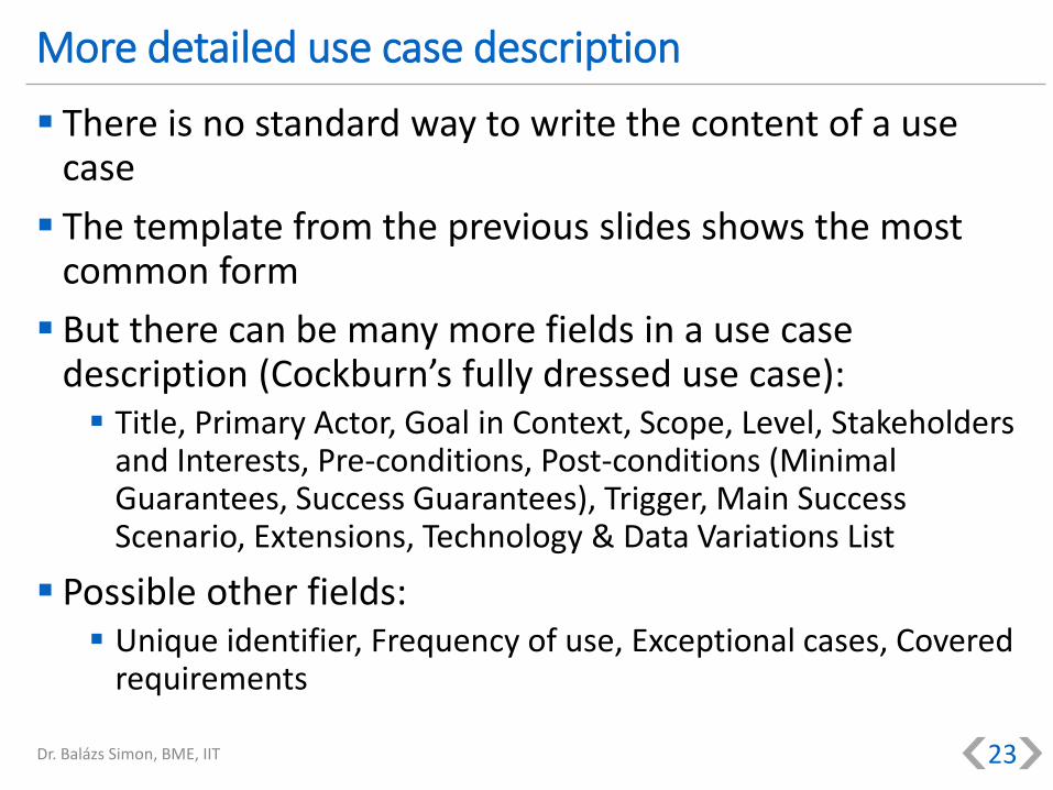
There is no standard way to write the content of a use case
The template from the previous slides shows the most common form
But there can be many more fields in a use case description (Cockburn’s fully dressed use case): Title, Primary Actor, Goal in Context, Scope, Level, Stakeholders
and Interests, Pre-conditions, Post-conditions (Minimal Guarantees, Success Guarantees), Trigger, Main Success Scenario, Extensions, Technology & Data Variations List
Possible other fields: Unique identifier, Frequency of use, Exceptional cases, Covered
requirements
Dr. Balázs Simon, BME, IIT 23

Webshop
Customer
Admin
Login
Place order
Manage user privileges
Login via Google
Login via Facebook
Modify order
<<extend>>
Make payment
<<include>>
Use Case Diagram: System boundary box (optional)
System boundary box: a box that sets a system scope to use cases all use cases outside the box are outside the scope of that system
Dr. Balázs Simon, BME, IIT 24
System boundary
System name
Order management
User management
Customer
Admin
Login
Place order
Manage user privileges
Login via Google
Login via Facebook
Modify order
<<extend>>
Make payment
<<include>>
Use Case Diagram: Package (optional)
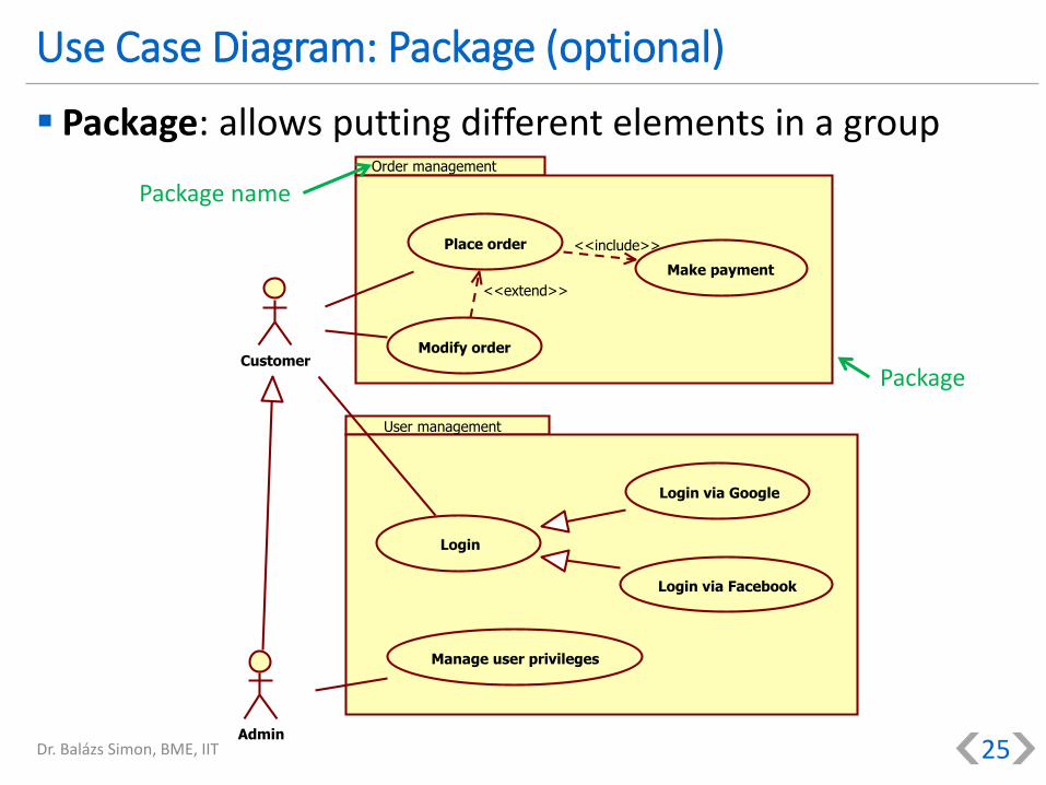
Package: allows putting different elements in a group
Dr. Balázs Simon, BME, IIT 25
Package
Package name

UML diagram types
Dr. Balázs Simon, BME, IIT 26
Use case diagram
Deployment diagram
Component diagram
Class diagram Package diagram
Object diagramComposite
structure diagramProfile diagram
Activity diagram Sequence diagramCommunication
diagram
State diagram Timing diagramInteraction
overview diagram
Structural UML diagrams:
Behavioral UML diagrams:

Activity Diagram
Dr. Balázs Simon, BME, IIT 27

Activity Diagram
Activity diagrams are graphical representations of workflows of stepwise activities and actions with support for choice, iteration and concurrency
Activity diagrams are typically used for modeling: the behavior captured by a single use case
a business process or workflow between users and the system
the steps of an algorithm
Activity diagrams provide a formal way of describing functionalrequirements as workflows
Activity diagrams can be developed in various levels of detail e.g. first at a high abstraction level, then at a lower abstraction level
by refining the stepsDr. Balázs Simon, BME, IIT 28
Requirements Design Implementation Testing Delivery Maintenance

Reminder from earlier: Buy item use case
Dr. Balázs Simon, BME, IIT 29
Use case: Buy item
Actors: Customer, Cashier
Main Success Scenario: 1. The Customer picks the item 2. The Customer hands the item to the Cashier 3. The Cashier records the item 4. The Cashier asks for money from the Customer 5. The Customer pays the amount to the Cashier 6. The Cashier gives the item and the receipt to the Customer
Alternative 5.A: 5.A.1. The Customer has not enough money 5.A.2. The Customer leaves empty handed
Customer
Buy item
Cashier

Customer Cashier
Hand item over
Pick an item
Record item
Ask money
Leave empty handed Pay money
Accept money
Give item and receipt
[ not enough money ] [ has enough money ]
Activity Diagram example: Buy item use case I.
Dr. Balázs Simon, BME, IIT 30
Partition
Partition
Initial node
Activity
Control flow
Partition name
item
money
Object
Object flow

Hand item over
Pick an item
Record item
Ask money
Leave empty handed Pay money
Accept money
Give item and receipt
Leave with item and receipt
[ not enough money ] [ has enough money ]
Activity Diagram example: Buy item use case II.
Dr. Balázs Simon, BME, IIT 31
Final node
item
money
Final node
Decision nodeGuard
condition
item and
receipt

Activity Diagram
Activity: used to model the individual steps in the behavior specified by the Activity
Diagram
Initial node: acts as a starting point for executing an activity has no incoming edges an activity can have multiple initial nodes: in this case several flows start in this
activity
Control flow: directed connection between two activities (source and target) designates flow of execution: the target activity is started when the source
activity is completed
Final node: at the final node the execution flow is stopped
Decision: chooses between outgoing control flows based on their guard conditions at most one outgoing flow is executed
Guard condition: condition attached to a control flow the flow can only become active if the guard condition evaluates to true
Dr. Balázs Simon, BME, IIT 32

Activity Diagram
Partition: a user (role) or part of the system along a dimension drawn as a swimlane activities inside the swimlane are performed by the
corresponding user (role) or system part partitions can be hierarchic: they can have subpartitions
Partition name: name of the user (role) or part of the system corresponding to
the given partition shown in the header of the swimlane notation
Object: represents data that can be passed between activities
Object flow: carries data between activities
Dr. Balázs Simon, BME, IIT 33

Select item
Retrieve item
Make item
[ item in stock ]
[ out of stock ]
Send item
Activity Diagram: decision and merge
Decision: chooses between outgoing flows
at most one outgoing flow is executed based on the guard conditions
Merge: brings together multiple flows without synchronization
if multiple incoming flows are active, merge is executed multiple times
Dr. Balázs Simon, BME, IIT 34
Guard condition
Merge
Decision
Guard condition

Activity Diagram: fork and join
Fork: flow is split into multiple concurrent (parallel) flows
Join: synchronizes (awaits) multiple flows
by default all incoming flows must complete so that the Join can be executed(this behavior can be overridden through a join expression)
Dr. Balázs Simon, BME, IIT 35
Select destination Select departure and return time
Reserve flight
Reserve hotel
Rent a car
Print reservations
Fork Join

Activity Diagram: call activity
Call activity: a call activity invokes another activity
the behavior of the invoked activity can also be described by an Activity Diagram
hence, activities can be nested within each other
Activity Diagrams can show different levels of detail
Dr. Balázs Simon, BME, IIT 36
Call activity
Take time off work Make travel reservations Travel
Activity Diagram: final nodes
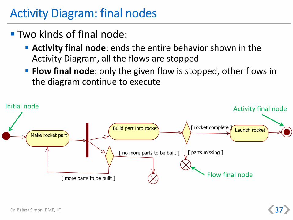
Two kinds of final node: Activity final node: ends the entire behavior shown in the
Activity Diagram, all the flows are stopped
Flow final node: only the given flow is stopped, other flows in the diagram continue to execute
Dr. Balázs Simon, BME, IIT 37
Make rocket part
Build part into rocket
[ more parts to be built ]
[ no more parts to be built ] [ parts missing ]
Launch rocket[ rocket complete ]
Activity final node
Flow final node
Initial node

Activity Diagram: signals
Activities can also be started by events (signals) instead of an initial node
Events can be accepted at the beginning or even in the middle of a behavior described by an Activity Diagram
Actions related to signals: Accept event action: waits for an event (signal) to occur, and starts a
new flow when it does Send signal action: sends a signal, which can be accepted by an accept
event action
Dr. Balázs Simon, BME, IIT 38
Process orderReceive order Request payment Payment confirmed Ship order
Accept event action Accept event action
Send signal action

Activity Diagram: time events
Accept time event action: starts a flow in the activity diagram at a definite point in time
Examples:
Dr. Balázs Simon, BME, IIT 39
Make ice cream Put the ice cream into the freezer Eat the ice cream
Wait 2 hours
Create monthly report
End of month
Accept time event action
Accept time event action

UML diagram types
Dr. Balázs Simon, BME, IIT 40
Use case diagram
Deployment diagram
Component diagram
Class diagram Package diagram
Object diagramComposite
structure diagramProfile diagram
Activity diagram Sequence diagramCommunication
diagram
State diagram Timing diagramInteraction
overview diagram
Structural UML diagrams:
Behavioral UML diagrams:

Component Diagram
Dr. Balázs Simon, BME, IIT 41

Component Diagram
A software component is a unit of composition with contractually specified interfaces and explicit context dependencies only. A software component can be deployed independently and is subject to third-party composition. (Szyperski)
The Component Diagram shows the components of a system and the connections between them
The Component Diagram is usually used during design, but can be successively refined in deployment and run-time
Dr. Balázs Simon, BME, IIT 42
Requirements Design Implementation Testing Delivery Maintenance

Component Diagram example: Mobile+web application
Dr. Balázs Simon, BME, IIT 43
Mobile client<<component>>
Website<<component>>
Business logic<<component>>
Data<<component>>
An overview Component Diagram shows components related by dependencies
Dependency: “A” depends on “B” means that if “B” changes then the change may affect “A”, too
The kind of the dependency is not specified
Lack of dependency where there are no dependency arrows
Component
Dependency(Website depends on Business logic)

Component notation
Three possible notations, they are equivalent: rectangle with icon
rectangle with component keyword (stereotype)
rectangle with component keyword (stereotype) and icon
Dr. Balázs Simon, BME, IIT 44
WebsiteWebsite
<<component>>Website
<<component>>
Stereotype Stereotype IconIcon

Component Diagram example: Computer
A more detailed Component Diagram shows components with their provided and required interfaces and the connections between them
Dr. Balázs Simon, BME, IIT 45
Business logic<<component>>
Website
<<component>>
Data<<component>>
Mobile client
<<component>>
IWeb
IData
Component
Provided interface
Required interface
Interface name
IClient

Component Diagram example: Computer
Provided and required interfaces can be wired through dependencies
Dr. Balázs Simon, BME, IIT 46
Business logic<<component>>
Website
<<component>>
Data<<component>>
Mobile client<<component>>
IWeb
IData
IClient
Component
Provided interface
Required interface
Interface nameIClient
IWeb IData Dependency

Business logic
<<component>>
IData<<interface>>
IClient<<interface>>
IWeb<<interface>>
<<use>>
47
Provided and required interfaces
Three possible notations, they are equivalent: component with lollipops and sockets
component with compartments
component with realizations and dependencies
Dr. Balázs Simon, BME, IIT
Business logic
<<component>>
IData
IWebBusiness logic<<component>>
provided interfaces
IWeb
required interfaces
IClient
IData
IClient
Required interface(socket)
Provided interface(lollipop)
Provided interfacescompartment
Required interfacescompartment
Interface(see later...)
Realization
Dependency

Composite component
A composite component is implemented by other components
Externally provided and required interfaces are exposed through ports
Delegation connectors connect externally provided and required interfaces to internal components that realize or require them
Dr. Balázs Simon, BME, IIT 48
Business logic<<component>>
Save and load
<<component>>
Game logic<<component>>
IDataIWeb
IData
IWeb ISaveLoad
Port
Delegationconnector
Delegationconnector
Port
internal structure
IClientIClient

UML diagram types
Dr. Balázs Simon, BME, IIT 49
Use case diagram
Deployment diagram
Component diagram
Class diagram Package diagram
Object diagramComposite
structure diagramProfile diagram
Activity diagram Sequence diagramCommunication
diagram
State diagram Timing diagramInteraction
overview diagram
Structural UML diagrams:
Behavioral UML diagrams:

Deployment Diagram
Dr. Balázs Simon, BME, IIT 50

Deployment Diagram
The Deployment Diagram specifies constructs that can be used to define the execution architecture of a system and the assignment of software artifacts to system elements
Deployment Diagrams can be used to model the hardware and software topology of the system
The Deployment Diagram is usually used during delivery for planning the deployment architecture
Dr. Balázs Simon, BME, IIT 51
Requirements Design Implementation Testing Delivery Maintenance
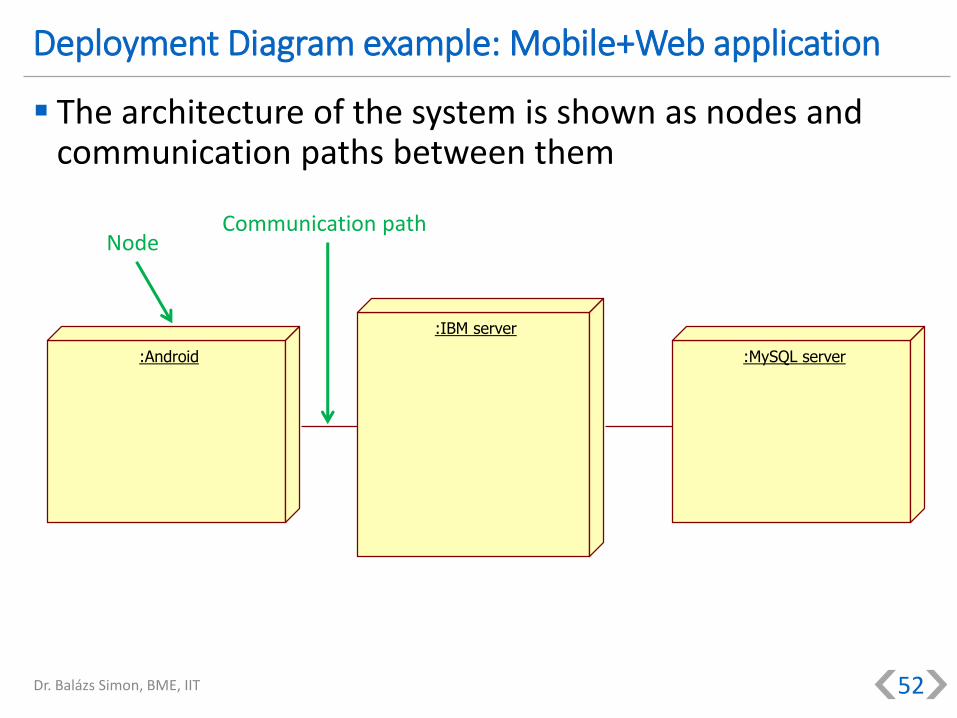
Deployment Diagram example: Mobile+Web application
The architecture of the system is shown as nodes and communication paths between them
Dr. Balázs Simon, BME, IIT 52
:Android
:IBM server
:MySQL server
NodeCommunication path

Artifacts example: Mobile+web application
Dr. Balázs Simon, BME, IIT 53
An artifact represents some (usually reifiable) item of information that is used or produced by a software development process or by operation of a system e.g. executable file, script, database table, document, etc.
An artifact can be a manifestation of a component
Mobile client<<component>>
Website<<component>>
Business logic<<component>>
Data<<component>>
Data.sql<<artifact>>
Business.jar<<artifact>>
Website.jar<<artifact>>
client.apk<<artifact>>
<<manifest>>
<<manifest>>
<<manifest>> <<manifest>>
Artifact
Component
Manifestation

Deployment Diagram example: Mobile+Web application
Artifacts can be deployed to nodes
Dependencies can also be shown between artifacts
Dr. Balázs Simon, BME, IIT 54
NodeCommunication path
:IBM server
:MySQL server:Android
Website.jar
<<artifact>>
Business.jar<<artifact>>
Data.sql<<artifact>>
client.apk<<artifact>>
ArtifactDependency

Deployment Diagram example: Mobile+Web application
The deployed artifacts can also be assigned to nodes using dashed arrows with deploy keyword (stereotype) (this diagram is equivalent with the one on the previous slide)
Dr. Balázs Simon, BME, IIT 55
NodeCommunication path
:IBM server :MySQL server:Android
Website.jar<<artifact>>
Business.jar<<artifact>>
Data.sql<<artifact>>
client.apk<<artifact>>
<<deploy>> <<deploy>> <<deploy>> <<deploy>>
Artifact Dependency
Deployment

UML diagram types
Dr. Balázs Simon, BME, IIT 56
Use case diagram
Deployment diagram
Component diagram
Class diagram Package diagram
Object diagramComposite
structure diagramProfile diagram
Activity diagram Sequence diagramCommunication
diagram
State diagram Timing diagramInteraction
overview diagram
Structural UML diagrams:
Behavioral UML diagrams:

Summary
Dr. Balázs Simon, BME, IIT 57

Summary
Software engineering
Modeling
Unified Modeling Language (UML)
UML Diagrams: Use Case Diagram
Activity Diagram
Component Diagram
Deployment Diagram
Dr. Balázs Simon, BME, IIT 58

UML diagram types
Dr. Balázs Simon, BME, IIT 59
Use case diagram
Deployment diagram
Component diagram
Class diagram Package diagram
Object diagramComposite
structure diagramProfile diagram
Activity diagram Sequence diagramCommunication
diagram
State diagram Timing diagramInteraction
overview diagram
Structural UML diagrams:
Behavioral UML diagrams: