unified facilities criteria (ufc) non-expeditionary …bridges can be classified according to the...
TRANSCRIPT
UFC 3-310-08 17 July 2018
UNIFIED FACILITIES CRITERIA (UFC)
APPROVED FOR PUBLIC RELEASE; DISTRIBUTION UNLIMITED
NON-EXPEDITIONARY BRIDGE INSPECTION, MAINTENANCE,
AND REPAIR
UFC 3-310-08 17 July 2018
UNIFIED FACILITIES CRITERIA (UFC)
NON-EXPEDITIONARY BRIDGE INSPECTION, MAINTENANCE, AND REPAIR
Any copyrighted material included in this UFC is identified at its point of use. Use of the copyrighted material apart from this UFC must have the permission of the copyright holder. U.S. ARMY CORPS OF ENGINEERS NAVAL FACILITIES ENGINEERING COMMAND AIR FORCE CIVIL ENGINEER CENTER (Preparing Activity) Record of Changes (changes are indicated by \1\ ... /1/) Change No. Date Location
This UFC supersedes UFC 3-310-08, Non-Expeditionary Bridge Inspection, Maintenance, and Repair, dated 16 August 2010.
UFC 3-310-08 17 July 2018
FOREWORD
The Unified Facilities Criteria (UFC) system is prescribed by MIL-STD 3007 and provides planning, design, construction, sustainment, restoration, and modernization criteria, and applies to the Military Departments, the Defense Agencies, and DOD Field Activities in accordance with USD (AT&L) Memorandum dated 29 May 2002. UFC will be used for all DOD projects and work for other customers where appropriate. All construction outside of the United States is also governed by Status of Forces Agreements (SOFA), Host Nation Funded Construction Agreements (HNFA), and, in some instances, Bilateral Infrastructure Agreements (BIA). Therefore, the acquisition team must ensure compliance with the more stringent of the UFC, the SOFA, the HNFA, and the BIA, as applicable. UFC are living documents and will be periodically reviewed, updated, and made available to users as part of the Services’ responsibility for providing technical criteria for military construction. Headquarters, U.S. Army Corps of Engineers (HQUSACE), Naval Facilities Engineering Command (NAVFAC), and the Air Force Civil Engineer Center (AFCEC) are responsible for administration of the UFC system. Military Departments, the Defense Agencies, and DOD Field Activities should contact the preparing Service for document interpretation and improvements. Technical content of UFC is the responsibility of the cognizant DOD working group. Recommended changes with supporting rationale should be sent to the respective Service proponent office by the following electronic form: Criteria Change Request. The form is also accessible from the Internet site listed below.
• UFC are effective upon issuance and are distributed only in electronic media from the following source: Whole Building Design Guide web site http://dod.wbdg.org/.
Refer to UFC 1-200-01, DoD Building Code (General Building Requirements), for implementation of new issuances on projects.
AUTHORIZED BY:
LARRY D. McCALLISTER, PhD, PE, PMP, SES
JOSEPH E. GOTT, P.E. Chief Engineer Naval Facilities Engineering Command Chief, Engineering and Construction
Directorate of Civil Works U.S. Army Corps of Engineers
NANCY J. BALKUS, P.E., SES, DAF MICHAEL McANDREW Deputy Director of Civil Engineers DCS Logistics, Engineering and Force Protection (HAF/A4C) HQ, United States Air Force
Deputy Assistant Secretary of Defense (Facilities Investment and Management) Office of the Assistant Secretary of Defense (Energy, Installations, and Environment)
UFC 3-310-08 17 July 2018
UNIFIED FACILITIES CRITERIA (UFC)
REVISION SUMMARY SHEET
Document: UFC 3-310-08, Non-Expeditionary Bridge Inspection, Maintenance, and Repair
Superseding: UFC 3-310-08, Non-Expeditionary Bridge Inspection, Maintenance, and Repair, dated 16 August 2010
Description: This document provides guidance to ensure military garrison/base bridges remain safely in operation and behave reliably for civilian and military traffic.
Reasons for Document: • Purpose: To ensure that military installation bridges remain safely in operation
and perform reliably for civilian and military traffic. The bridges inspected, operated, and maintained by military agencies should meet or exceed the same standards to which bridges under U.S. civilian jurisdiction are subject.
• Application: This UFC provides direction so all military installation bridges are appropriately inspected and the results reported in accordance with current federal standards, Federal Highway Administration (FHWA) criteria, and Federal Railway Administration (FRA) criteria. This UFC also provides direction to ensure all military installation bridges are maintained and repaired in a consistent manner and in accordance with industry standards.
Impact: The publication of UFC 3-310-08 will not result in any increased cost to the Services. Each Service is already in compliance with the National Bridge Inspection Standards (NBIS) and the reporting requirements directed by the Code of Federal Regulations, Title 23, Part 650, Subpart C, and Title 49, Subtitle B, Chapter II, Part 237. The provisions in this UFC are already being accomplished by each Service as directed by separate Service documents (Army ER 1110-2111, Air Force ETL 07-5 [superseded by this UFC], and Navy UG-60020-OCN).
Unification Issues: Not applicable; all agencies affected by this UFC are subject to the same requirements.
UFC 3-310-08 17 July 2018
i
TABLE OF CONTENTS CHAPTER 1 INTRODUCTION ....................................................................................... 1
1-1 BACKGROUND. .................................................................................................. 1
1-2 PURPOSE. ........................................................................................................... 1
1-3 SCOPE. ................................................................................................................ 1
1-4 REFERENCES. .................................................................................................... 1
CHAPTER 2 DOD BRIDGE INSPECTION AND MANAGEMENT PROGRAM .............. 3
2-1 ORGANIZATIONAL STRUCTURE – RESPONSIBILITIES AND QUALIFICATIONS. ......................................................................................................... 3
2-1.1 National Bridge Program Manager. ................................................................... 3
2-1.2 Installation Bridge Manager. ............................................................................. 3
2-1.3 Load Rating Engineer. ...................................................................................... 4
2-1.4 Railroad Bridge Engineer. ................................................................................. 4
2-1.5 Railroad Bridge Inspector.................................................................................. 4
2-1.6 Inspection Team Leader (Highway Bridges). .................................................... 4
2-1.7 Underwater Bridge Inspector. ........................................................................... 4
2-1.8 Hydraulic Bridge Engineer. ............................................................................... 5
2-2 BRIDGE INVENTORY DATA REQUIREMENTS. ................................................ 5
2-2.1 Components of Bridge File. ............................................................................... 5
2-2.2 File Retention/Data Storage. ............................................................................. 5
2-3 QUALITY CONTROL/QUALITY ASSURANCE REQUIREMENTS. .................... 6
CHAPTER 3 HIGHWAY BRIDGES ................................................................................ 7
3-1 DEFINITIONS. ...................................................................................................... 7
3-1.1 Highway. ........................................................................................................... 7
3-1.2 Public Road. ...................................................................................................... 7
3-1.3 Bridge. .............................................................................................................. 7
3-1.4 Strategic Highway Corridor Network (STRAHNET) ........................................ 10
3-2 NATIONAL BRIDGE INVENTORY (NBI) HIGHWAY BRIDGES. ...................... 10
3-2.1 History of the NBIS Program. .......................................................................... 10
3-2.2 Bridge Inspection Requirements. .................................................................... 10
3-2.3 Load Rating and Posting Requirements. ........................................................ 15
3-2.4 Bridge Inventory Data Requirements. ............................................................. 16
3-2.5 Deficiencies and Critical Findings. .................................................................. 17
UFC 3-310-08 17 July 2018
ii
3-3 NON-NBI HIGHWAY BRIDGES. ........................................................................ 17
3-3.1 Short Span and Non-Public Highway Bridges. ................................................ 17
3-3.2 Highway Bridges in Foreign Territories. .......................................................... 17
3-3.3 Bridge Inventory Data Requirements. ............................................................. 18
CHAPTER 4 RAILROAD BRIDGES ............................................................................. 19
4-1 INTRODUCTION. ............................................................................................... 19
4-1.1 History of FRA Railroad Bridge Inspection Regulations. ................................. 19
4-1.2 Applicability. .................................................................................................... 20
4-1.3 Railroad Bridges Reportable to FHWA. .......................................................... 20
4-2 BRIDGE INSPECTION REQUIREMENTS. ........................................................ 20
4-2.1 Inspection Types. ............................................................................................ 20
4-2.2 Inspection Procedures. ................................................................................... 24
4-3 LOAD RATING AND LOAD RESTRICTION REQUIREMENTS. ....................... 25
4-4 BRIDGE MANAGEMENT PROGRAM REQUIREMENTS. ................................ 25
CHAPTER 5 PEDESTRIAN BRIDGES AND GOLF CART BRIDGES ......................... 27
5-1 BRIDGE INSPECTION REQUIREMENTS. ........................................................ 27
5-2 LOAD RATING REQUIREMENTS. .................................................................... 27
5-3 BRIDGE INVENTORY DATA REQUIREMENTS. .............................................. 27
CHAPTER 6 SPECIAL BRIDGE TYPES ...................................................................... 29
6-1 COMPLEX BRIDGES. ....................................................................................... 29
6-2 TAXIWAY BRIDGES. ......................................................................................... 29
6-3 MILITARY BRIDGE SET TRUSS PANEL BRIDGES. ....................................... 29
6-4 MODEL AND TRAINING BRIDGES. ................................................................. 29
CHAPTER 7 COMMON REQUIREMENTS OF ALL BRIDGES ................................... 31
7-1 CRITICAL FINDINGS. ........................................................................................ 31
7-1.1 Inspection Procedures and Reporting. ............................................................ 31
7-1.2 Prioritizing Maintenance Procedures. ............................................................. 32
7-1.3 Plan of Action (POA). ...................................................................................... 32
7-1.4 Repair. ............................................................................................................ 32
7-2 SCOUR EVALUATION. ..................................................................................... 33
7-2.1 Scour Screening. ............................................................................................ 33
7-2.2 Unknown Foundation Coding. ......................................................................... 33
7-2.3 Higher Level Scour Analysis. .......................................................................... 33
UFC 3-310-08 17 July 2018
iii
7-2.4 2D Hydraulic Model. ........................................................................................ 34
7-2.5 Unknown Foundation Risk Analysis. ............................................................... 34
7-2.6 Unknown Foundation Evaluation. ................................................................... 34
7-2.7 Scour Critical POA. ......................................................................................... 34
7-3 FRACTURE CRITICAL PLAN. .......................................................................... 35
7-4 SEISMIC EVALUATION. ................................................................................... 35
7-5 TRAFFIC SAFETY DEVICES. ........................................................................... 35
7-6 CLOSED BRIDGES. .......................................................................................... 36
CHAPTER 8 BRIDGE MAINTENANCE ........................................................................ 37
8-1 INTRODUCTION. ............................................................................................... 37
8-2 INDUSTRY PRACTICE. ..................................................................................... 37
CHAPTER 9 BRIDGE REPAIR .................................................................................... 39
9-1 INTRODUCTION. ............................................................................................... 39
9-2 INDUSTRY PRACTICE. ..................................................................................... 39
APPENDIX A REFERENCES ....................................................................................... 41
APPENDIX B BEST PRACTICES ................................................................................ 47
B-1 MILITARY LOAD CLASSIFICATION (MLC) AND MILITARY VEHICLE LIVE LOAD DATA. ................................................................................................................ 47
B-2 CRITERIA FOR NATIONAL BRIDGE PROGRAM MANAGER TO ALTER INSPECTION INTERVAL. ............................................................................................ 64
B-2.1 Procedure for FHWA Approval of Increased Inspection Intervals. .................. 64
B-2.2 Template for Requesting Increasing Bridge Inspection Interval to Four Years for Qualifying Bridges. ................................................................................................... 65
B-3 POINT OF CONTACT INFORMATION FOR SERVICE BRANCHES. .............. 68
B-4 STATE LEGAL LOAD LIMITS FOR POSTING. ................................................ 69
B-5 SIMPLIFIED HIGHWAY BRIDGE INSPECTION FLOWCHART. ...................... 70
B-6 EXAMPLE FATIGUE-PRONE DETAIL FORM FOR FCM PLAN. ..................... 71
B-7 EXAMPLE SCOUR CRITICAL BRIDGE PLAN OF ACTION. ........................... 72
B-8 FLOW CHART FOR CRITICAL FINDINGS. ...................................................... 73
B-9 EXAMPLE CRITICAL INSPECTION FINDING REPORT. ................................. 74
B-10 ORGANIZATIONAL RESPONSIBILITIES. .................................................... 75
APPENDIX C GLOSSARY ........................................................................................... 79
UFC 3-310-08 17 July 2018
iv
FIGURES Figure 3-1 NBIS Bridge Length ....................................................................................... 9 Figure B-1 Wheeled Bending Moment .......................................................................... 60 Figure B-2 Tracked Bending Moment ............................................................................ 61 Figure B-3 Wheeled Shear ............................................................................................ 62 Figure B-4 Tracked Shear ............................................................................................. 63
TABLES Table B-1 Standard Classes of Hypothetical Vehicles .................................................. 48 Table B-2 Wheeled- and Tracked-Vehicle Moment (kip-feet) ........................................ 52 Table B-3 Wheeled- and Tracked-Vehicle Shear (tons) ................................................ 56 Table B-4 National Bridge Program Manager (NBPM) and Installation Bridge Manager
(IBM) Responsibilities by Service ........................................................................... 75
UFC 3-310-08 17 July 2018
1
CHAPTER 1 INTRODUCTION
1-1 BACKGROUND.
In an effort to develop a coherent and consistent Department of Defense (DOD) policy for the inspection, evaluation, maintenance, and repair of installation bridges, this UFC was created to consolidate evolving federal bridge inspection and industry standards. As federal and state regulations, standards, guidelines, and procedures continually change, it is critical to remain current with the industry and update this UFC to ensure compliance with all bridge inspection, evaluation, load rating, maintenance, and repair requirements.
1-2 PURPOSE.
This UFC defines requirements for inspection, maintenance, and repair of bridges on military installations in accordance with current federal and industry standards. In particular, highway bridges must conform to Federal Highway Administration (FHWA) criteria (23 CFR 650 Subpart C) while railroad bridges must conform to Federal Railroad Administration (FRA) criteria (49 CFR 237). The purpose of these requirements is to ensure military installation bridges can safely and reliably carry civilian and military traffic. All bridges inspected, operated, and maintained by military agencies should meet or exceed the same standards to which bridges under U.S. civilian jurisdiction are subject.
1-3 SCOPE.
This UFC applies to all military installation bridges, whether located in the contiguous United States (CONUS) or outside the contiguous United States (OCONUS), including Alaska, Hawaii, U.S. territories and possessions, and foreign territories. Installation bridges can be classified according to the type of traffic “over” the bridge as 1) highway bridges, 2) railroad bridges, 3) pedestrian bridges, 4) golf cart bridges, or 5) taxiway bridges. This UFC does not apply to expeditionary bridges located in military theaters of operation. This UFC does not apply to Army Corps of Engineers civil works bridges located outside of an installation.
1-4 REFERENCES.
Appendix A contains a list of references used in this UFC.

UFC 3-310-08 17 July 2018
2
This Page Intentionally Left Blank
UFC 3-310-08 17 July 2018
3
CHAPTER 2 DOD BRIDGE INSPECTION AND MANAGEMENT PROGRAM
This chapter provides technical requirements for a bridge inspection and management program. Refer to the appropriate sections in this UFC for inspection, load rating, reporting, maintenance, and repair requirements for each type of bridge.
2-1 ORGANIZATIONAL STRUCTURE – RESPONSIBILITIES AND QUALIFICATIONS.
The U.S. Code of Federal Regulations (23 CFR 650.305 and 49 CFR 237) requires each Military Department to establish and maintain a bridge inspection and management program. At the head of each program is a National Bridge Program Manager who enforces the bridge program in accordance with the Military Department’s policies.
Point of contact information for each Military Department’s bridge program is found in Appendix B, paragraph B-3.
The credentials, qualifications, and responsibilities of the key bridge program positions are described below. The fulfillment of these duties can be accomplished using in-house personnel, contracted personnel, or personnel from another government agency.
2-1.1 National Bridge Program Manager.
The National Bridge Program Manager for each Military Department provides overall leadership and inspection guidance for every bridge in the Department’s bridge inventory (CONUS and OCONUS). The National Bridge Program Manager must successfully complete an FHWA-approved comprehensive bridge inspection training course followed by an FHWA-approved refresher training course every subsequent five years. Also, the National Bridge Program Manager must either be a licensed professional engineer (P.E.) or have 10 years of bridge inspection experience. The National Bridge Program Manager should have a general understanding of all aspects of bridge engineering, including design, load rating, new construction, rehabilitation, inspection or condition evaluation, and maintenance.
Refer to Appendix B, paragraph B-10, Table B-4, for delineation of responsibilities between the National Bridge Program Manager and Installation Bridge Managers for each Military Department.
2-1.2 Installation Bridge Manager.
An Installation Bridge Manager typically carries out responsibilities delegated from the National Bridge Program Manager at a specific military installation as delineated in Appendix B, paragraph B-10, Table B-4. The Installation Bridge Manager must have completed an FHWA-approved comprehensive bridge inspection training course and must complete an FHWA-approved refresher training course every five years after completing the FHWA-approved comprehensive training course.
UFC 3-310-08 17 July 2018
4
2-1.3 Load Rating Engineer.
As required by 23 CFR 650.309(c), each Military Department must designate a Load Rating Engineer who will be responsible for ensuring load ratings are performed as specified in this UFC. The individual responsible for load rating calculations or determining a load rating by engineering judgment must be a P.E.
For railroad bridges falling under the jurisdiction of the FRA bridge safety standards, 49 CFR 237, the Load Rating Engineer must also meet the requirements of 49 CFR 237.51 and be designated as a Railroad Bridge Engineer.
2-1.4 Railroad Bridge Engineer.
Railroad bridge inspection, maintenance, and load rating functions must be performed under the direction of a Railroad Bridge Engineer. A Railroad Bridge Engineer is a person determined by the track owner to be competent to perform the functions identified in 49 CFR 237.51(a). These functions include determining forces and stresses in railroad bridges and bridge components, prescribing safe loading conditions for railroad bridges, prescribing inspection and maintenance procedures for railroad bridges, and designing repairs and modifications to railroad bridges.
A Railroad Bridge Engineer must meet the educational qualifications as specified in 49 CFR 237.51(b), including either an engineering degree from an accredited program or current registration as a P.E.
2-1.5 Railroad Bridge Inspector.
A Railroad Bridge Inspector must meet the requirements specified in 49 CFR 237.53.
2-1.6 Inspection Team Leader (Highway Bridges).
The Inspection Team Leader must meet the requirements specified in 23 CFR 650.305. Inspection Team Leaders must complete an FHWA-approved refresher training course every five years after completing the FHWA-approved comprehensive training course.
2-1.7 Underwater Bridge Inspector.
The underwater bridge inspection diver must have a commercial diver certification. Diver training certification must conform to Section 30.A.06 of Army Engineering Manual (EM) 385-1-1, Safety and Health Requirements. An underwater bridge inspection diver who does not meet the qualifications of paragraph 2-1.6 must have completed an FHWA-approved comprehensive bridge inspection training course or other FHWA-approved underwater bridge inspection training course. Underwater Bridge Inspection Team Leader requirements are the same as those listed in paragraph 2-1.6. All underwater inspections will be under the direct supervision of a qualified Inspection Team Leader with underwater inspection experience.
UFC 3-310-08 17 July 2018
5
Underwater inspector qualifications must meet host country underwater diver qualifications in addition to the requirements of the National Bridge Inspection Standards (NBIS) and with the approval of the National Bridge Program Manager.
2-1.8 Hydraulic Bridge Engineer.
Hydraulic Bridge Engineers performing scour calculations must be licensed P.E.s and have relevant work experience in bridge hydraulic modeling and scour evaluations.
2-2 BRIDGE INVENTORY DATA REQUIREMENTS.
2-2.1 Components of Bridge File.
Complete, accurate, and current bridge records must be maintained in a bridge file for each National Bridge Inventory (NBI) highway bridge in accordance with AASHTO MBE-2-M, The Manual for Bridge Evaluation, Section 2. It is recommended that bridge files for all other bridges follow this format. The bridge file provides a full history of the structure, including construction drawings, as-built drawings, photographs, damage, repairs, and capacity calculations. At a minimum, significant bridge file components that must be maintained include:
• Inspection reports
• Waterway information (channel cross-sections, soundings, stream profiles)
• Significant correspondence
• Special inspection procedures or requirements
• Load rating documentation, including load testing results
• Posting documentation
• Critical findings and actions taken
• Scour assessment
• Scour plan of action (POA) for scour critical bridges and those with unknown foundations and documentation of post-event inspection or follow-up
• Inventory and evaluation data and collection/verification forms.
Refer to Section 2 of AASHTO MBE-2-M, The Manual for Bridge Evaluation; 49 CFR 237.33; and FHWA-PD-96-001, Recording and Coding Guide for the Structure Inventory and Appraisal of the Nation’s Bridges, for additional information regarding bridge files.
2-2.2 File Retention/Data Storage.
File retention and organization policies will be determined by the National Bridge Program Manager. Each Military Department’s National Bridge Program Manager will determine the storage location in accordance with Section 2 of AASHTO MBE-2-M.
UFC 3-310-08 17 July 2018
6
Bridge files must be readily accessible to the Installation Bridge Manager. It is highly recommended that hard copies of inspection reports and load ratings be maintained for two full inspection cycles (typically 48 months). Electronic copies of components of the bridge file, inspection reports, and load ratings will be maintained in perpetuity, along with bridge inventory database information. If components of the bridge file are found to be deficient or incomplete, a plan of corrective action will be developed to remedy future recordkeeping procedures.
2-3 QUALITY CONTROL/QUALITY ASSURANCE REQUIREMENTS.
The National Bridge Program Manager will determine the specific procedures for quality control (QC) and quality assurance (QA) reviews. At a minimum, 5 percent of bridge inspection teams and 5 percent of the inspected bridges will be audited annually in some manner (e.g., through field reviews of inspection teams or office reviews of inspection reports). FHWA Bridge Inspector’s Reference Manual (BIRM), Topic 1.3.4, discusses the FHWA-recommended QC/QA framework.
As part of the QC/QA framework, the bridge management program will identify QC and QA responsibilities.
Once established, QC/QA procedures for each agency must be compiled in a manual that is readily available to all personnel involved with bridge inspection; this manual will be updated to reflect any procedural changes.

UFC 3-310-08 17 July 2018
7
CHAPTER 3 HIGHWAY BRIDGES
3-1 DEFINITIONS.
3-1.1 Highway.
A “highway” is defined by 23 U.S.C. 101(a)(11) as follows:
(11) Highway. - The term "highway" includes –
(A) a road, street, and parkway;
(B) a right-of-way, bridge, railroad-highway crossing, tunnel, drainage structure including public roads on dams, sign, guardrail, and protective structure, in connection with a highway.
Therefore, all roads on military installations are considered to be “highways.”
3-1.2 Public Road.
A “public road” is defined by 23 U.S.C. 101(a)(21) as follows:
(21) Public road. - The term "public road" means any road or street under the jurisdiction of and maintained by a public authority and open to public travel.
Since roads on military installations are typically accessible to military personnel, government civilians, contractor personnel, and retired personnel, all road bridges on military installations are deemed to be public highway bridges regardless of the bridge’s access restrictions unless the Installation Commander designates otherwise (with the Military Department’s National Bridge Program Manager’s approval). Non-public designations will be avoided unless warranted by special circumstances.
3-1.3 Bridge.
A “bridge” is defined in 23 CFR 650.305 as follows:
“A structure including supports erected over a depression or an obstruction, such as water, highway, or railway, and having a track or passageway for carrying traffic or other moving loads, and having an opening measured along the center of the roadway of more than 20 feet (6.1 meters) between undercopings of abutments or spring lines of arches, or extreme ends of openings for multiple boxes; it may also include multiple pipes, where the clear distance between openings is less than half of the smaller contiguous opening.”
The method to measure bridge length is depicted in Figure 3-1 as taken from FHWA-PD-96-001.
The NBIS apply to installation highway bridges (in U.S. states and territories) that meet the length requirement above. Highway bridges that meet the length requirements
UFC 3-310-08 17 July 2018
8
specified in the NBIS are required to be included in the NBI. Requirements for installation bridges in foreign territories have similar requirements, as described in paragraph 3-3.2.
Culverts also qualify as bridges if the preceding definition applies. Culverts that do not meet the preceding definition may be managed similarly to other installation drainage structures.

UFC 3-310-08 17 July 2018
9
Figure 3-1 NBIS Bridge Length
UFC 3-310-08 17 July 2018
10
3-1.4 Strategic Highway Corridor Network (STRAHNET)
FHWA-PD-96-001 defines the Strategic Highway Corridor Network (STRAHNET) and connectors as a system of highways that are strategically important to the defense of the United States. There are no STRAHNET highways or connectors carried by bridges on military installations. For situations where an installation owns a bridge over a STRAHNET highway or connector, refer to the description of item 5A in FHWA-PD-96-001 for coding instructions.
3-2 NATIONAL BRIDGE INVENTORY (NBI) HIGHWAY BRIDGES.
All NBI highway bridges must be inspected in accordance with the NBIS. These standards establish minimum federal requirements for inspection procedures, inspection intervals, personnel qualifications, inspection reports, and bridge inventory records. Although not reproduced verbatim in this UFC, the standards are listed in Appendix A as a reference. The NBIS should be consulted whenever a question arises regarding federal inspection requirements.
The FHWA has developed 23 metrics for the oversight of the National Bridge Inspection Program. Agencies and installations must take the necessary steps to remain compliant with the NBIS as determined by FHWA and the 23 metrics. Refer to FHWA Metrics for the Oversight of the National Bridge Inspection Program for additional information.
3-2.1 History of the NBIS Program.
Several catastrophic bridge failures since 1967 have led to the creation of and modifications to federal laws that constitute the FHWA-managed NBIS. The NBIS provides requirements for inspecting highway bridges and reporting bridge conditions annually in the NBI database. The procedures to implement the NBIS requirements are explained in the BIRM. For a more comprehensive history of the National Bridge Inspection Program, refer to the BIRM, Chapter 1.
3-2.2 Bridge Inspection Requirements.
3-2.2.1 Inspection Types and Interval.
Bridge inspections are conducted to determine the physical condition of the structure, to develop the basis for load rating analyses, to assess the need for maintenance, and to track the functional condition and rate of deterioration over time. There are seven inspection types requiring unique levels of effort: initial/inventory, routine, damage, in-depth, fracture critical, underwater, and special.
Descriptions of and the required inspection intervals for each type of inspection are specified below. The inspection intervals may be altered but must meet all applicable NBIS criteria. See Appendix B, paragraph B-2, for inspection interval alteration procedures. Late inspections require a justification of unusual circumstances (e.g., natural disaster, ongoing bridge construction activity) and will be included in the bridge file.

UFC 3-310-08 17 July 2018
11
3-2.2.1.1 Initial/Inventory Inspection.
The initial/inventory inspection is the first inspection after a bridge is built or added to the installation real property and becomes a part of the bridge file. Elements of the initial/inventory inspection will also apply when there has been a change in configuration of the structure (e.g., widening, lengthening, and supplemental bents). It is important for the inspectors to identify any existing problems or locations in the structure where potential problems may arise. An initial inspection must provide all Structure Inventory and Appraisal (SI&A) data. A thorough review of as-built plans will be conducted prior to the initial inspection and the inspector will note any fracture critical members (FCM) or details during this inspection. A Level 1 scour screening is required if the bridge crosses over a waterway. A revised or new load rating may be required with the initial inspection if the rating was not part of the construction submittal or if repairs affected the structural capacity. The initial/inventory inspection documents the baseline condition assessment of the bridge.
Initial/inventory inspections must be performed within 90 days of the bridge opening to traffic. New bridges must be added to the installation real property and become a part of the bridge file prior to opening to traffic.
3-2.2.1.2 Routine Inspection.
Routine inspections are regularly scheduled inspections serving to collect observations and measurements of any changes from the initial inspection or any previously conducted inspection. The routine inspection must be performed and reported in accordance with NBIS requirements.
All routine inspections will be conducted at regular intervals not to exceed 24 months. The National Bridge Program Manager may increase routine inspection intervals for bridges that meet the criteria for increased inspection intervals discussed in Appendix B, paragraph B-2.
3-2.2.1.3 Damage Inspection.
Damage inspections are one-time unscheduled inspections performed after environmental events or human actions such as collisions, floods, or earthquakes. Damage inspections are performed to 1) determine if structural damage has occurred, 2) evaluate the extent of any structural damage, and 3) determine the level of effort for required repairs.
Damage inspections must be performed within a reasonable time after a natural disaster or human-caused action. The inspectors must document all damaged members, measuring, at a minimum, any section loss, member misalignment, and any loss of foundation support. The inspection must provide all of the information necessary to determine if bridge closure is required or to perform an emergency load restriction.
Local installation personnel may make an initial assessment of the bridge if personnel meeting required inspector qualifications are not immediately available. The results of the initial damage assessment will be forwarded to the Installation Bridge Manager for

UFC 3-310-08 17 July 2018
12
review. Based on the information in the initial damage assessment, the Installation Bridge Manager will determine if additional resources (e.g., additional inspection, testing, load rating, design) are required to fully evaluate or correct the damaged condition. The Installation Bridge Manager or National Bridge Program Manager may recommend a follow-up in-depth inspection of the bridge to monitor the structure.
3-2.2.1.4 In-Depth Inspection.
In-depth inspections are hands-on, close-up inspections of one or more members above or below the waterline. In-depth inspections are more detailed and may require special access techniques to inspect areas not easily detectable in a routine inspection.
In-depth inspections are required every 24 months for fracture critical bridges. For other bridge types, in-depth inspections may be performed after damage or other special inspections are performed, at the direction of the Installation Bridge Manager or National Bridge Program Manager. For small bridges, the in-depth inspection includes inspection of all critical members of the structure. For large and complex structures, these inspections may be scheduled separately for defined segments of the bridge or bridge elements, connections, or details. 3-2.2.1.5 Fracture Critical Inspection.
Fracture critical inspections are detailed, hands-on inspections of steel bridges with FCMs that may include visual or other nondestructive evaluations. Prior to inspection, a thorough review of the design or as-built plans, fracture-critical inspection plan, previous inspection reports, load rating, and fatigue-prone details must be made. In the absence of plans or identification of fatigue-prone details, the inspector should be able to determine the fatigue-prone details based on the information provided in Table 6.6.1.2.3-1 of AASHTO LRFDUS-7, LRFD Bridge Design Specifications. FCMs require a “hands-on” inspection, where the inspector is capable of touching the area being inspected (arm’s length). Physical inspection methods may be necessary to more accurately assess the condition of an FCM. Advanced inspection methods may need to be employed, including nondestructive testing (NDT) methods. The hands-on inspection should identify and note the condition of problematic details prone to crack development.
For more information regarding inspection techniques for fracture critical bridges, refer to the BIRM or FHWA-NHI-11-015, Fracture Critical Inspection Techniques for Steel Bridges Participant Workbook. For additional information and case studies on fatigue damage in welded, bolted, and riveted structures, refer to FHWA Manual for Inspecting Bridges for Fatigue Damage Conditions and John W. Fisher’s Fatigue and Fracture in Steel Bridges – Case Studies.
Fracture critical inspections will be conducted at regular intervals not to exceed 24 months. In order to establish the criteria for fracture critical inspection intervals and level of effort, factors such as bridge age, fatigue-prone details, and known deficiencies will be considered.
UFC 3-310-08 17 July 2018
13
3-2.2.1.6 Underwater Inspection.
3-2.2.1.6.1 Underwater inspections include diving to visually inspect and measure bridge components, probing for scour or undermining, and sounding to locate the bottom of the channel. The inspection must include such methods as necessary to adequately perform a condition assessment of the structure. If a bridge can be adequately inspected by wading, shallow probing, or with the use of cameras at low water conditions, a formal underwater inspection (divers) is not required. For bridges that do not require a formal underwater inspection, Item 93B on the SI&A form will not be coded. The Installation Bridge Manager will ensure inspections occur at low water conditions while maintaining compliance with the required bridge inspection schedule.
3-2.2.1.6.2 According to the BIRM, there are three levels of underwater inspection intensity:
• Level 1 – Visual, tactile inspection
• Level 2 – Detailed inspection with partial cleaning
• Level 3 – Highly detailed inspection with NDT or partially destructive testing (PDT)
3-2.2.1.6.3 Bridge inspectors must examine previous inspection reports or gather sufficient bridge and channel information to determine which level of underwater inspection is required when contracted or tasked to perform underwater inspections for specific bridges.
3-2.2.1.6.4 Level 1 inspections are required for all routine underwater inspections and will be performed within arm’s reach of the areas being inspected. Visual inspections are performed across the entire submerged structure, but, in areas of poor water clarity, a tactile sweeping motion of the hands and arms may be used to inspect the entire substructure.
3-2.2.1.6.5 Level 2 inspections include cleaning off marine or aquatic growth at critical inspection areas and inspecting high-stress, damaged, and deteriorated areas that may be shielded by the growth. Critical areas near the low waterline, mudline, and midway between will be inspected. Piers and abutments will have at least 1 square foot (0.09 square meter) cleaned at three or more levels on each face. For structures greater than 50 feet (15.2 meters) in length, an additional three levels will be cleaned at each exposed face. For piles, horizontal bands a minimum of 10 inches (254 millimeters) long will be cleaned along the following locations:
• Rectangular – At least three sides
• Octagonal – At least six sides
• Round – At least 75 percent of circumference
• H-pile – At least the outside faces of flanges and one side of web
UFC 3-310-08 17 July 2018
14
3-2.2.1.6.6 Level 2 inspection is recommended for 10 percent of all underwater elements.
3-2.2.1.6.7 Level 3 inspections include the complete cleaning of a structural element and NDT or PDT. Detailed measurements will be made along with testing techniques such as ultrasonic, physical material sampling, or boring. These inspections are generally performed when a structural repair or possible replacement is being considered.
3-2.2.1.6.8 Level 3 inspections are recommended for members that require repair or rehabilitation.
3-2.2.1.6.9 For additional information, it may be helpful to review FHWA-NHI-10-027, Underwater Bridge Inspection. This report contains valuable information on underwater inspection techniques, underwater repair techniques, and scour issues.
3-2.2.1.6.10 Underwater inspections must be completed at regular intervals not to exceed 60 months. The Installation Bridge Manager may decrease the interval of underwater inspections based on Level 1 or Level 2 scour evaluations, evidence of substructure movement, stream migration, bank sloughing, or debris buildup. Any deviation in the underwater inspection interval must be documented in the bridge file. FHWA-NHI-10-027 provides guidance for alterations to underwater inspection intervals.
3-2.2.1.7 Special Inspection.
Special inspections monitor a known member deficiency or other conditions that warrant special attention, such as foundation settlement or scour, fatigue damage, severe section loss, critical findings, or the public’s use of a load posted bridge. These inspections are not usually comprehensive enough to meet NBIS requirements for routine inspections.
Based on the recommendations in the inspection reports, the Installation Bridge Manager will determine when special inspections are required. Special inspections are scheduled based on the severity of the deficiency/condition being monitored and the anticipated rate of continued deterioration (i.e., special inspections for scour should be performed after high-water events; special inspections for section loss should be at three-, six-, or twelve-month intervals, based on the severity of deterioration and its effect on the bridge’s safe load capacity).
For bridges that do not require a formal special inspection, Items 92C and 93C on the SI&A form will not be coded. For bridges where items 92C and 93C are coded, a separate report for this inspection is required. If the inspection is conducted in conjunction with other inspections, the scope, procedures, findings, and recommendations must be recorded in a separate paragraph in the bridge inspection report.
UFC 3-310-08 17 July 2018
15
3-2.2.2 Inspection Procedures.
Each bridge must be inspected in accordance with 23 CFR 650. Guidance on various bridge inspection procedures is provided in the BIRM and AASHTO MBE-2-M. A minimum of one qualified team leader must be present at all times during initial, routine, in-depth, FCM, and underwater inspections.
3-2.3 Load Rating and Posting Requirements.
For new bridge design, load rating calculations must be a contract deliverable. Load ratings will be performed during all initial inspections or when no previous load rating exists. During routine, in-depth, fracture critical, underwater, or special inspections, any changed conditions identified that may alter the load rating will be forwarded to the Load Rating Engineer for review. If damage, deterioration, or structure alterations noted during the inspection are determined by the Load Rating Engineer to be significant, an updated load rating will be performed and load restriction may be required.
The load rating report must clearly state basic information about the bridge (e.g., configuration, material type, age), method of analysis, references, and all assumptions used to establish a valid load rating.
3-2.3.1 AASHTO Load Ratings.
Load rating must be performed for all roadway bridges that meet the NBIS definition of a bridge (over 20 feet [6.1 meters] measured along the centerline of the roadway). The load rating must be calculated in accordance with AASHTO MBE-2-M. For highway bridges on an installation in foreign territory, if the foreign country’s bridge code is more stringent than AASHTO, the foreign bridge code will govern the load rating. Posting of bridges (including the specific sign) for civilian vehicles, when determined to be necessary from the load rating, will be in accordance with local requirements (typically, state legal load limits or the foreign code legal load limits); see Appendix B, paragraph B-4, for state posting loads. Highway bridges must have load ratings for special hauling vehicles (SHV) per FHWA’s Load Rating of Specialized Hauling Vehicles Memorandum. All NBI bridges must have valid load rating calculations in the bridge file.
3-2.3.2 Military Load Classification (MLC) Load Ratings.
All installation highways that have or will have military tactical vehicles traveling on them must have military load classification (MLC) load ratings on file for the bridges. The MLC is determined using the procedures in AASHTO MBE-2-M, with the live loads shown in Appendix B, paragraph B-1. MLC methods in Army Field Manuals and Training Aids are not permitted. Appropriate MLC signs must be placed at both ends of the bridge; this must be done for all vehicular bridges requiring a load rating (i.e., all roadway bridges over 20 feet [6.1 meters] long). If an installation or roadway is deemed as “administrative” only, with no military vehicle usage, the Installation Bridge Manager may waive, at the approval of the National Bridge Program Manager, the MLC load rating requirement for the bridge. Posting of “No Tactical Vehicles on Bridge” may be required. Additionally, MLC is determined for military tactical vehicle use of the bridge only; it is not considered part of the load rating information submitted to FHWA.

UFC 3-310-08 17 July 2018
16
3-2.3.3 Limited Information Bridges.
Bridges with limited as-built information (i.e., no design drawings or calculations) must be rated based on as-inspected field measurements and/or the procedures in Section 6.1.4 of AASHTO MBE-2-M. When material sampling from the structure is not possible, refer to the current version of AASHTO MBE-2-M for material specifications based on the approximate year of construction. The load rating report must clearly state basic information about the bridge (e.g., configuration, material type, age), method of analysis, references, and all assumptions used to establish a valid load rating. In the absence of previous design, as-built, or shop drawings, it is recommended to field-measure all member dimensions necessary to establish as-built properties for the load rating analysis.
Inventory and operating level ratings may be assigned based on design loading, given the bridge meets the requirements of the FHWA memorandum, Action: Assigned Load Ratings, dated September 29, 2011.
3-2.3.4 Load Posting of Bridges.
Bridges where the load rating determines that the safe load-carrying capacity is below statutory (most often the state or host nation) levels will be posted for a load restriction. The maximum safe load, as determined by the load rating, must be posted using signage in accordance with the FHWA Manual on Uniform Traffic Control Devices for Streets and Highways (MUTCD) R12 series signs or local requirements.
Installations will install load posting signs as soon as possible—no later than 90 days after notification that posting is required. In cases where known existing loads significantly exceed the recommended posting limit or the route is of significant importance (e.g., bus routes, emergency vehicle routes), posting more quickly is important to ensure safety.
Load posting signs must be placed at the bridge for each direction of travel, as well as a minimum of 0.25 mile (0.4 kilometer) in advance of the bridge, or at the location of the nearest intersection prior to the bridge, for each direction of travel.
3-2.4 Bridge Inventory Data Requirements.
All bridge records must be maintained by the installation, including the inspection reports, plans, and follow-up actions taken to address deficiencies identified during inspections. Findings will be recorded on standardized agency forms. Complex bridges and bridges with FCMs, underwater elements, or scour critical status must be identified and given special attention according to the appropriate procedures.
An inventory of all bridges must be maintained by the Military Department with jurisdiction over those bridges. Reporting of inspection data will be per each individual agency’s policy and FHWA-PD-96-001 (and FHWA-PD-96-001’s most current Errata Sheet). Inspection data, including inventory and appraisal data (SI&A data), will be collected and maintained for all bridges that are inspected. Refer to Appendix B, paragraph B-5, for a bridge inspection reporting flowchart.

UFC 3-310-08 17 July 2018
17
SI&A data will be entered into the agency’s inventory within 90 days of the date of updating, change, or editing.
3-2.5 Deficiencies and Critical Findings.
The Installation Bridge Manager is responsible for ensuring all deficiencies identified in bridge inspection reports are addressed as soon as possible. Maintenance issues and minor repairs can be addressed immediately using in-house resources. Other deficiencies require projects to be programmed following Military Department-specific procedures. The Installation Bridge Manager is responsible for programming and providing advocacy for projects addressing identified bridge deficiencies. The Installation Bridge Manager must ensure that critical findings are addressed in accordance with the procedures described in paragraph 7-1. The Installation Bridge Manager will maintain supporting documents showing the actions taken to address all deficiencies identified in the bridge inspection reports.
3-3 NON-NBI HIGHWAY BRIDGES.
Highway bridges in foreign territories and all other highway bridges that do not meet the span length or public road requirements of the NBIS are not included in the NBI and are referred to as “Non-NBI Highway Bridges.” The requirements for these bridges are described in the following paragraphs.
3-3.1 Short Span and Non-Public Highway Bridges.
3-3.1.1 Inspection Requirements.
Highway bridges that do not meet the NBIS span length and/or public road requirements must be inspected at a frequency interval of not greater than 48 months.
The National Bridge Program Manager can approve the exemption of short span bridges from the inspection requirement if engineering judgement indicates that failure of the bridge will not significantly endanger the safety of people or property.
3-3.1.2 Load Rating Requirements.
Highway bridges less than 20 feet (6.1 meters) and bridges deemed non-public will be load rated at the discretion of the National Bridge Program Manager.
3-3.2 Highway Bridges in Foreign Territories.
3-3.2.1 Inspection Requirements.
Highway bridges in foreign territories meeting the NBIS span length and public road requirements must conform to the bridge inspection requirements of paragraph 3-2.2. The inspection interval may be extended without approval of the FHWA and at the discretion of the National Bridge Program Manager.
UFC 3-310-08 17 July 2018
18
3-3.2.2 Load Rating Requirements.
Highway bridges in foreign territories meeting the NBIS span length and public road requirements must conform to the load rating requirements of paragraph 3-2.3.
3-3.3 Bridge Inventory Data Requirements.
An inventory of non-NBI bridges must be maintained by the Military Department with jurisdiction over those bridges. It is not necessary to transmit SI&A data to the FHWA for bridges on any installation in foreign territory or for “non-NBI” bridges owned by DOD. There is one exception to this: the FHWA needs to be advised about “non-NBI” bridges that go over a Federal-Aid highway, STRAHNET route or connector, or other important structure. Inventory data (not appraisal information) on bridges that fall into this category should be reported if no record of the bridge has been previously reported or if the bridge is modified. Refer to Appendix B, paragraph B-5, for a bridge inspection reporting flowchart.
For the purposes of internal recordkeeping, each agency’s standard SI&A form may be further modified, as desired, to better reflect bridge data in a foreign territory.
UFC 3-310-08 17 July 2018
19
CHAPTER 4 RAILROAD BRIDGES
4-1 INTRODUCTION.
Railroad bridges differ from other types of bridges in the types of live loads they undergo, in their modes of failure and distress, and in their construction details. The FRA requires that all track owners have an implemented railroad bridge safety management program including, but not limited to, clear definitions of the roles and responsibilities of all designated qualified personnel; an inventory of all railroad bridges; bridge capacities through load ratings; and detailed bridge inspection policies. Refer to 49 CFR 237 for additional information.
4-1.1 History of FRA Railroad Bridge Inspection Regulations.
Regular inspection of railroad bridges has been an industry practice for over 100 years. Railroad operators learned early in their development through bridge failures, often resulting in fatalities, the importance of comprehensive bridge inspections to ensure that developing flaws did not lead to catastrophe. In 1968, as a result of the Silver Bridge collapse at Point Pleasant, West Virginia, the President established a White House Task Force on Bridge Safety. In support of this task force, the Association of American Railroads (AAR) organized the AAR Railroad Bridge Safety Committee. This committee solicited information from all the railroads in the United States on their bridge inspection, rating, and maintenance practices. Responses from all of the Class I railroads, which made up 94 percent of the nation’s railroad mileage, indicated that all of their bridges received a comprehensive inspection by qualified personnel at least once per year. The survey also revealed that every Class I railroad followed bridge inspection and rating practices equal to or greater than the instructions set forth in the Manual of Recommended Practice for Railway Engineering issued jointly by the AAR Engineering Division and the American Railway Engineering Association, a predecessor to the American Railway Engineering and Maintenance-of-Way Association (AREMA) Manual for Railway Engineering.
In 1995, the FRA issued an Interim Statement of Policy on the Safety of Railroad Bridges. This was followed in 2000 by a Final Statement of Agency Policy on the Safety of Railroad Bridges. These statements, while non-regulatory, established criteria for railroads to use to ensure the structural integrity of railroad bridges.
With the signing into law of the Railroad Safety Improvement Act of 2008, the FRA was directed to issue regulations requiring track owners to adopt and follow specific procedures to protect the safety of their bridges. As a result, the FRA issued its Bridge Safety Standards, Final Rule, on July 15, 2010. The rule became effective on September 13, 2010, with a staggered implementation schedule whereby the largest freight and passenger railroads were required to comply first, followed by the mid-size and then the smallest railroads.

UFC 3-310-08 17 July 2018
20
4-1.2 Applicability.
FRA bridge safety standards apply to all railroad bridges located within CONUS, Alaska, or Hawaii supporting a track with a gage of 2 feet (0.6 meter) or more used to transport freight in railcars moved by railroads that are part of the general railroad system of transportation. Railroad bridges on military installations that meet these criteria fall under the jurisdiction of FRA and must comply with regulations in 49 CFR 237.
The following railroads (and bridges) on military installations do not fall under the jurisdiction of the FRA. However, non-FRA railroad bridges must also be inspected and managed in accordance with UFC paragraphs 4-2, 4-3, and 4-4.
• Bridge structures in foreign territories
• Bridge structures supporting track used exclusively for rapid transit operations
• Bridge structures located within an installation that are not part of the general railroad system and over which the movement of rail equipment is performed only by military or installation employees
4-1.3 Railroad Bridges Reportable to FHWA.
Railroad bridges that go over a Federal-Aid highway, STRAHNET route or connector, or other important structure, must be reported to the FHWA. Inventory data (not appraisal information) on bridges that fall into this category must be reported if no record of the bridge has been previously reported or if the bridge is modified.
4-2 BRIDGE INSPECTION REQUIREMENTS.
4-2.1 Inspection Types.
Bridge inspections are conducted to determine the physical condition of the structure, to develop the basis for load rating analyses, to assess the need for maintenance, and to track the functional condition and rate of deterioration over time. There are seven inspection types requiring unique levels of effort. These inspection types are initial/inventory, routine, damage, in-depth, fracture critical, underwater, and special, as described below.
Any railroad bridge that has been out of service and has not received an inspection within the scheduled time specified in the Railroad Bridge Management Program will be inspected by a Railroad Bridge Inspector and the report reviewed and approved by a Railroad Bridge Engineer prior to reopening to service. Where deemed necessary by the Railroad Bridge Engineer, an updated load rating will be performed for the bridge and filed in the bridge file prior to reopening to service. Late inspections require an explanation to be included in the bridge file.

UFC 3-310-08 17 July 2018
21
4-2.1.1 Initial/Inventory Inspection.
The initial/inventory inspection is the first inspection after a bridge is built or added to the installation real property and becomes a part of the bridge file. Elements of the initial/inventory inspection may also apply when there has been a change in configuration of the structure (e.g., widening, lengthening, supplemental bents). It is important for the inspectors to identify any existing problems or locations in the structure where potential problems may arise. A thorough review of as-built plans should be conducted prior to the initial inspection and the inspector should note any FCMs or details during this inspection. A Level 1 scour screening is required if the bridge crosses over a waterway.
Initial inspections must be performed within 90 days of opening to rail traffic. A new railroad bridge must be added to the installation real property and becomes a part of the bridge file prior to opening.
4-2.1.2 Routine Inspection.
A routine inspection is a regularly scheduled inspection to collect observations and measurements of any changes from the initial inspection or any previously conducted inspection.
All routine inspections must be conducted at least once each calendar year, with no more than 540 days between any successive inspections. The Railroad Bridge Engineer may increase routine inspection intervals based on the physical or functional condition of the bridge. It is the responsibility of the Railroad Bridge Engineer to establish criteria for decreased inspection intervals.
4-2.1.3 Damage Inspection.
A damage inspection is a one-time unscheduled inspection to evaluate structural damage resulting from environmental or human actions such as collisions, floods, derailments, fires, or earthquakes, and is performed to establish the repair level of effort. Damage inspections must be performed within a reasonable time after a natural disaster or human-caused action. The inspectors will document all damaged members, measuring, at a minimum, any section loss, member misalignment, and any loss of foundation support. The inspection must provide all information necessary to potentially close the bridge or perform an emergency load restriction. Local installation personnel may make an initial assessment of the bridge if personnel meeting required inspector qualifications are not immediately available. The National Bridge Program Manager may recommend a follow-up in-depth inspection of the bridge to monitor the structure. The National Bridge Program Manager will maintain bridge damage inspection procedures within the railroad bridge management program specific to each event type. Examples of bridge damage inspection instructions are provided in AREMA Manual for Railway Engineering, Volume 2, Chapter 10.
UFC 3-310-08 17 July 2018
22
4-2.1.4 In-Depth Inspection.
An in-depth inspection is a hands-on, close-up inspection of one or more members above or below the waterline. In-depth inspections are more detailed and may require special access techniques to inspect areas not easily detectable from a routine inspection. The Railroad Bridge Engineer is responsible, in conjunction with the Installation Bridge Manager, for establishing the need for and required interval of an in-depth inspection.
4-2.1.5 Fracture Critical Inspection.
Fracture critical inspections are detailed, hands-on inspections of steel bridges with FCMs that may include visual or other nondestructive evaluations. Prior to inspection, a thorough review of the design or as-built plans, previous inspection reports, load rating, and fatigue-prone details must be made. In the absence of plans or fatigue-prone details, the inspector should be able to determine the fatigue-prone details based on the details provided in Table 6.6.1.2.3-1 of AASHTO LRFDUS-7. FCMs require a “hands-on” inspection where the inspector is capable of touching the area being inspected (arm’s length). Physical inspection methods may be necessary to more accurately assess the condition of an FCM. Advanced inspection methods may need to be employed, including NDT methods. The hands-on inspection will identify and note the condition of problematic details prone to crack development.
For more information regarding inspection techniques for fracture critical bridges, refer to the BIRM or FHWA-NHI-11-015. For additional information and case studies on fatigue damage in welded, bolted, and riveted structures, refer to FHWA’s Manual for Inspecting Bridges for Fatigue Damage Conditions and John W. Fisher’s Fatigue and Fracture in Steel Bridges – Case Studies.
Fracture critical inspections must be conducted at regular intervals not to exceed 24 months. When a routine inspection interval is decreased due to a FCM finding, it is recommended that the fracture critical inspection interval be decreased to match the routine inspection interval. In order to establish the criteria for fracture critical inspection intervals and level of effort, factors such as bridge age, fatigue-prone details, and known deficiencies must be considered.
4-2.1.6 Underwater Inspection.
4-2.1.6.1. An underwater inspection is diving to visually inspect and measure bridge components, probing for scour or undermining, and sounding to locate the bottom of the channel. The inspection will include such methods as necessary to adequately perform a condition assessment of the structure. If a bridge can be adequately inspected by wading, shallow probing, or with the use of cameras at low water conditions, a formal underwater inspection (divers) is not required. For bridges that do not require a formal underwater inspection, Item 93 on the SI&A form will not be coded. The Installation Bridge Manager will develop a mechanism to ensure inspections occur at low water conditions.
UFC 3-310-08 17 July 2018
23
4-2.1.6.2. These inspections must be performed by experienced inspectors determined by the Railroad Program Manager to be competent in underwater inspection procedures. It is recommended that the Underwater Inspection Bridge Inspectors are divers qualified per paragraph 2-1.7 and have completed an approved equivalent to the FHWA-approved underwater bridge inspection diver training course.
4-2.1.6.3. According to the BIRM, there are three levels of underwater inspection intensity:
• Level 1 – Visual, tactile inspection
• Level 2 – Detailed inspection with partial cleaning
• Level 3 – Highly detailed inspection with NDT or PDT
4-2.1.6.4. Level 1 inspections are required for all routine underwater inspections and must be performed within arm’s reach of the areas being inspected. Visual inspections are performed across the entire submerged structure, but, in areas of poor water clarity, a tactile sweeping motion of the hands and arms may be utilized to cover the entire substructure.
4-2.1.6.5. Level 2 inspections include cleaning off marine or aquatic growth at critical inspection areas and inspecting high-stress, damaged, and deteriorated areas that may be shielded by the growth. Critical areas near the low waterline, mudline, and midway between will be inspected. Piers and abutments must have at least 1 square foot (0.09 square meter) cleaned at three or more levels on each face. For structures greater than 50 feet (15 meters) in length, an additional three levels must be cleaned at each exposed face. For piles, horizontal bands a minimum of 10 inches (254 millimeters) long will be cleaned along the following locations:
• Rectangular – At least three sides
• Octagonal – At least six sides
• Round – At least 75 percent of circumference
• H-pile – At least the outside faces of flanges and one side of web
4-2.1.6.6. Level 3 inspections include complete cleaning of a structural element and NDT or PDT. Detailed measurements are typically made along with testing techniques such as ultrasonic, physical material sampling, or boring. These inspections are generally performed when a structural repair or possible replacement is being considered.
4-2.1.6.7. Underwater inspections must be completed at regular intervals not to exceed 60 months. The Railroad Bridge Engineer may decrease the interval of underwater inspections based on Level 1 or Level 2 scour evaluations, evidence of substructure movement, stream migration, bank sloughing, or debris buildup. Any deviation in the underwater inspection interval must be documented in the bridge file. Prior to requesting an alteration to underwater inspection intervals, it may be helpful to review FHWA-NHI-10-027. This report not only lists various factors that affect the
UFC 3-310-08 17 July 2018
24
needed interval of underwater inspection but also contains valuable information on underwater inspection techniques, underwater repair techniques, and scour issues.
4-2.1.7 Special Inspection.
Inspections that monitor a known member deficiency or other conditions that warrant special attention, such as foundation settlement or scour, fatigue damage, severe section loss; or to evaluate damage caused by a natural or accidental event, including, but not limited to, flood, fire, earthquake, derailment, or vehicular or vessel impact. Based on these criteria, the Railroad Bridge Engineer will determine when special inspections are required. A special inspection must be performed based on the criteria in 49 CFR 237, Subpart E, Bridge Inspection.
4-2.2 Inspection Procedures.
The Railroad Bridge Engineer must specify the bridge inspection procedures in conformance with the requirements of 49 CFR 237. The bridge inspection procedures will include the following:
• Methods, means of access, and level of detail to be recorded for the various components of that bridge or class of bridges
• Assurance that the level of detail and the inspection procedures are appropriate to the bridge configuration, conditions found during previous inspections, the nature of the railroad traffic, and vulnerability of the bridge to damage
• Be designed to detect, report, and address deterioration and deficiencies before they present a hazard to safe train operation
Bridge inspections must be conducted under the direct supervision of a designated Railroad Bridge Inspector. A bridge or portion of a bridge may be inspected more frequently when a Railroad Bridge Engineer deems necessary, considering the conditions noted during previous inspections, bridge type and configuration, weight and frequency of rail traffic, and the type or nature of rail traffic. In addition, bridge inspection reports will be reviewed by Railroad Bridge Engineers and railroad bridge supervisors to:
• Determine whether inspections have been performed in accordance with the prescribed schedule and specified procedures
• Evaluate whether any items on the report represent a present or potential hazard to safety
• Prescribe any modifications to the inspection procedures or inspection interval for that particular bridge
• Determine the need for further higher-level review
UFC 3-310-08 17 July 2018
25
4-3 LOAD RATING AND LOAD RESTRICTION REQUIREMENTS.
All railroad bridges must have a load rating on file within the railroad bridge file performed by a Railroad Bridge Engineer. The load ratings will be expressed in terms of numerical values related to a standard system of train loads (i.e., Cooper E-equivalent configuration).
All railroad bridge load rating methods are recommended to abide by AREMA Manual for Railway Engineering, Volume 2, Chapter 7. Timber bridges are addressed in Chapter 7, concrete bridges are addressed in Chapter 8, and steel bridges are addressed in Chapter 15. As an alternative to evaluating the capacity of railroad bridge components within the aforementioned chapters, other methods prescribed by the Railroad Bridge Engineer may be utilized, such as strain gage data, deflection measurements, or non-destructive testing for identifying embedded concrete reinforcement. All methods used to determine the capacity of the bridge must be clearly stated in the bridge file.
In addition, the Railroad Bridge Engineer will issue instructions specifying the maximum equipment weight along with either the minimum equipment length or axle spacing. These instructions are for use by those persons responsible for controlling the movement of rail equipment over railroad bridges to ensure the bridges are not overloaded. For railroad bridges that present horizontal or vertical restrictions, the Railroad Bridge Engineer will issue instructions necessary to prevent damage from over-dimension loads. Refer to 49 CFR 237.73 for further information.
4-4 BRIDGE MANAGEMENT PROGRAM REQUIREMENTS.
The National Bridge Program Manager is responsible for maintaining the railroad bridge management program and ensuring its continued compliance with this UFC and FRA guidelines. At a minimum, the program must include all of the following:
• An accurate inventory of railroad bridges
• A record of the safe load capacity of each bridge
• A provision to obtain and maintain design documents, including repairs, modifications, and inspections of each bridge
• A bridge inspection program covering as a minimum: o Inspection personnel safety considerations;
o Types of inspection, including required detail;
o Definitions of defect levels and associated condition codes if condition codes are used;
o The method of documenting inspections, including standard forms or formats;
o Structure type and component nomenclature; and
UFC 3-310-08 17 July 2018
26
o Numbering or identification protocol for substructure units, spans, and individual components
The railroad bridge management program must include, at a minimum, the following requirements:
• Record of each inspection required to be performed
• Record of an inspection will be prepared from notes taken on the day(s) the inspection was made and will be dated with the date(s) the physical inspection takes place and the date the record is created
• Each bridge inspection report must include, at a minimum, the following information: o A precise identification of the bridge inspected;
o Date on which the physical inspection was completed;
o Identification and written or electronic signature of the inspector;
o Type of inspection performed;
o Identification of inspection findings requiring expedited or critical review by a Railroad Bridge Engineer and any restrictions placed at the time of inspection;
o Condition of components inspected; and
o Identification of the portions of the bridge that were inspected
• Initial report of each bridge will be placed in the bridge file within 30 calendar days of the completion of inspection
• Complete report of each bridge inspection within 120 calendar days of the completion of the inspection
Refer to 49 CFR 237.109 for additional information on what FRA requires for bridge inspection records.

UFC 3-310-08 17 July 2018
27
CHAPTER 5 PEDESTRIAN BRIDGES AND GOLF CART BRIDGES
5-1 BRIDGE INSPECTION REQUIREMENTS.
Pedestrian bridges and golf cart bridges must be inspected at a minimum interval of 48 months if the bridge crosses a highway, crosses a railroad, or if failure of the bridge could significantly endanger the safety of people or property. The National Bridge Program Manager approves the bridges requiring inspection and the required inspection interval.
5-2 LOAD RATING REQUIREMENTS.
Pedestrian bridges and golf cart bridges must be load rated if the bridge crosses a highway, crosses a railroad, or if failure of the bridge could endanger the safety of people or property. If a pedestrian bridge load rating is less than 60 pounds per square foot (psf) (293 kilograms per square meter), the bridge must be posted for reduced pedestrian traffic. If a pedestrian bridge load rating is performed and found to be less than 40 psf (195 kilograms per square meter), the bridge must be closed to pedestrian traffic until it is repaired. AASHTO GSDPB-2-UL, LRFD Guide Specifications for Design of Pedestrian Bridges, is a good reference for this topic.
Pedestrian and golf cart bridges intended to support maintenance or emergency vehicles will meet the load rating and inspection requirements of highway bridges. These bridges must be posted and barricaded or equipped with bollards to prevent non-emergency vehicle use.
5-3 BRIDGE INVENTORY DATA REQUIREMENTS.
An inventory of inspected pedestrian and golf cart bridges must be maintained by the Military Department with jurisdiction over those bridges. Do not include these bridges in the NBI provided to FHWA. However, the FHWA must be advised about bridges that go over a Federal-Aid highway, STRAHNET route or connector, or other important structure. Inventory data (not appraisal information) on bridges that fall into this category will be reported if no record of the bridge has been previously reported or if the bridge is modified. Refer to Appendix B, paragraph B-5, for a bridge inspection reporting flowchart.

UFC 3-310-08 17 July 2018
28
This Page Intentionally Left Blank
UFC 3-310-08 17 July 2018
29
CHAPTER 6 SPECIAL BRIDGE TYPES
6-1 COMPLEX BRIDGES.
Complex bridges must be inspected and reported to the FHWA per the requirements specified in the UFC. Complex bridges include movable, suspension, and cable-stayed bridges, as well as other bridges with unusual characteristics. The National Bridge Program Manager will identify specialized bridge inspection procedures and any additional inspector training and experience necessary to safely and accurately perform the inspections.
6-2 TAXIWAY BRIDGES.
All taxiway bridges must be inspected at least every two years and load rated to ensure the bridge can safely carry airfield traffic. All requirements for NBI bridges apply for taxiway bridges. Since the NBI requires reporting of only highway bridges based on the type of traffic “over” the bridge, taxiway bridges over highways will not be included in the NBI reporting to FHWA.
6-3 MILITARY BRIDGE SET TRUSS PANEL BRIDGES.
Although originally intended for temporary, battlefield applications, prefabricated military bridge sets (i.e., Bailey and Mabey-Johnson or similar truss panel bridges) often remain in use in a permanent capacity. Army Technical Manual (TM) 3-34.23, M2 Bailey Bridge, contains useful information on the Bailey system and load capacities.
Because there are many variations of the Bailey and Mabey-Johnson bridge systems, it is recommended that the manufacturer’s literature be consulted prior to performing a load rating of these bridge types. In lieu of using the manufacturer’s loading data, it is also permissible to load-rate these bridges as a generic truss; however, this procedure will be time-consuming due to the amount of calculations involved.
Military bridge set bridges meeting the criteria for a reportable bridge must abide by the requirements of paragraph 3-2.
6-4 MODEL AND TRAINING BRIDGES.
Model and training bridges are commonly found on installations. They are often referred to as research, development, testing and evaluation (RDT&E) models, simulations, or replicas. These are not real property, are not reportable, and will not be part of the installation bridge inventory database, nor will they be part of the NBI. They must be closed off to all traffic (other than vehicles used for testing or training) and stored in a secure, locked area when not in use. If a load rating or actual regular traffic use on these bridges is desired, an initial inspection will be performed prior to adding the structure to the bridge inventory.

UFC 3-310-08 17 July 2018
30
This Page Intentionally Left Blank
UFC 3-310-08 17 July 2018
31
CHAPTER 7 COMMON REQUIREMENTS OF ALL BRIDGES
7-1 CRITICAL FINDINGS.
Critical findings are defined as structural or safety-related deficiencies that require immediate follow-up inspection or action. It is the responsibility of the National Bridge Program Manager to implement procedures for addressing critical deficiencies, including:
• Immediate critical deficiency reporting steps
• Emergency notification of police and the public
• Rapid evaluation of the deficiencies
• Rapid implementation of corrective or protective actions
• A tracking system to ensure adequate follow-up
• Provisions for identifying other bridges with similar structural details for follow-up inspections
The National Bridge Program Manager must establish a bridge program procedure to ensure that critical findings are addressed in a timely manner and in conformance with Appendix B, paragraph B-8, “Flow Chart for Critical Findings.” General steps must be taken to assure that critical findings are identified and resolved as quickly and efficiently as possible. Viable options include permanent repair, temporary repair, and restriction of load on a bridge. Refer to the BIRM, Topic 4.5, “Critical Findings,” for additional information and guidance on addressing critical findings.
7-1.1 Inspection Procedures and Reporting.
The bridge program procedure must require the immediate verbal notification of a potential critical finding to the National Bridge Program Manager and Load Rating Engineer. In addition to the verbal notification, the procedures should include a written notification following a standardized format in either hardcopy or electronic format. See Appendix B, paragraph B-9, for a sample Critical Inspection Finding Report form. The written notification should include notes, photographs, and sketches and/or drawings to accurately portray the potential critical finding. Temporary actions may also be taken to safeguard the public until proper repairs are completed. These actions may include:
• Load posting
• Traffic restrictions from the damaged area
• Speed restrictions
• Temporary lane closure
UFC 3-310-08 17 July 2018
32
• Temporary shoring
• Complete bridge closure
After submittal of the written report, the finding will be assessed and severity established with the proper repair strategy or POA. The procedures will require notification of critical findings for reportable highway bridges to the FHWA.
The BIRM, Chapter 4.5.3, lists numerous examples of critical findings for timber, steel, and concrete bridges, for both reduced load capacity and public safety hazard conditions.
7-1.2 Prioritizing Maintenance Procedures.
The National Bridge Program Manager must establish prioritization criteria to help facilitate maintenance work plan strategies. A list of example priority criteria can be found in the BIRM, Topic 4.5.
7-1.3 Plan of Action (POA).
A POA will be developed and approved within seven calendar days of a critical finding. It may be necessary to begin addressing a critical finding prior to full development and acceptance of a POA. It is the responsibility of the National Bridge Program Manager, in conjunction with the Installation Bridge Manager, to implement procedures for addressing critical deficiencies, including:
• Immediate critical deficiency reporting steps
• Emergency notification of police and the public
• Rapid evaluation of the deficiencies
• Rapid implementation of corrective or protective actions
• A tracking system to ensure adequate follow-up
• Provisions for identifying other bridges with similar structural details for follow-up inspections
7-1.4 Repair.
Critical findings that significantly impact a bridge’s structural integrity and/or create a safety hazard will be addressed immediately through complete or partial bridge closure or repair. A critical finding that impacts a bridge’s structural integrity will be retrofitted through short-term repairs (i.e., temporary shoring or bracing) or permanent repairs that are designed and constructed to restore the affected member(s) to their original load capacity. This may include installation of new structural steel plates or shapes; removal and replacement of deteriorated concrete and steel reinforcing; or installation of other
UFC 3-310-08 17 July 2018
33
materials (e.g., timber, steel cable, fiber reinforced polymer composites, masonry), depending on the structure type.
Critical findings that create a safety hazard (e.g., broken railings or safety devices that may not provide proper containment or redirection; loose concrete or steel that creates a falling hazard) will be isolated by removing traffic from the area of the hazard until the hazard is removed and/or repaired.
The FHWA will be notified annually of critical finding repairs and post-repair progress which impacts data for NBI highway bridges.
7-2 SCOUR EVALUATION.
7-2.1 Scour Screening.
All existing bridges must be screened to determine their vulnerability to scour. This includes, but is not limited to, a Level 1 stream stability analysis and a review of the existing bridge plans. Critical information from the bridge plans includes, but is not limited to, the foundation types, locations, and depths. If this level of analysis indicates that the bridge is not susceptible to scour then the bridge should be appropriately coded and continue to be monitored during each routine inspection. HEC-18, Evaluating Scour at Bridges, Table 10.2, provides a list of items to consider when assessing the susceptibility of a bridge to scour.
7-2.2 Unknown Foundation Coding.
For bridges with an unknown foundation and determined through a Level 1 stream stability analysis to not be susceptible to scour, Code Item 113 will remain “U” and a scour critical POA will be prepared until a higher-level analysis has been performed.
7-2.3 Higher Level Scour Analysis.
If after the initial screening the bridge is susceptible to scour, additional analysis is needed. This includes the evaluation of the flooding history of the bridge and the development of a hydraulic model (typically the Army Hydrologic Engineering Center’s River Analysis System [HEC-RAS]) to determine the scour potential at the bridge site. Higher level scour evaluations must be performed by a Hydraulic Bridge Engineer who is a professional engineer with relevant work experience in bridge hydraulic modeling and scour evaluations. This scour evaluation should also consider the potential for debris collecting on the bridge substructure. Previous inspection reports, along with the current channel stability and observed debris, will provide guidance. Once the theoretical (potential) scour depth is determined from the hydraulic model, this depth should be compared to the existing foundation depths so a determination can be made as to the bridge’s overall susceptibility to scour. This process involves a multi-disciplinary team approach that should include hydraulic, geotechnical, and structural engineers to determine the reasonableness of the results. If, after this analysis, any bridge can be considered unstable should the potential scour depth be reached, it should be considered “scour critical” and a POA, including a detailed plan for potential
UFC 3-310-08 17 July 2018
34
bridge closure, should be developed. See Appendix B, paragraph B-7, for an example Scour Critical Bridge POA.
7-2.4 2D Hydraulic Model.
Some bridge crossings, such as tidally influenced bridges or a wide floodplain that contains multiple bridges, will require a higher level of hydraulic analysis. A 2D hydraulic model will be conducted to analyze the scour susceptibility.
7-2.5 Unknown Foundation Risk Analysis.
Bridges are classified as having unknown foundations when the type and depth of foundations are unknown. The initial approach is to perform extensive data mining to ensure the foundations are in fact unknown. If the foundations are in fact unknown, HEC-18, Appendix F, provides guidance for performing a risk-based analysis to prioritize bridges for further evaluation. Each Military Department is responsible for implementing a risk-based approach to reclassify bridges with unknown foundations and subsequently evaluate the susceptibility to scour. HEC-18, Appendix F, recommends to first prioritize bridges based on their functional classification. Secondly, collect historical documentation of foundation and design practices based on the date of original construction, consider the subsurface conditions and bridge standards from nearby bridges, and/or perform proven NDT to assess foundation type and length. Once the information has been gathered, perform a scour evaluation based on the data and update Code Item 113 accordingly. If the scour evaluation determines the bridge to be scour critical (items to be coded with a 3, 2, or 1), a POA will be implemented for the bridge. For bridges with unknown foundations even after a risk analysis has been performed, a POA will be implemented that includes a bridge closure plan. FHWA Attachment “B” – Guidance for Developing and Implementing Plans of Action for Bridges with Unknown Foundations provides recommended steps for developing POAs for bridges with unknown foundations.
7-2.6 Unknown Foundation Evaluation.
FHWA and the Florida Department of Transportation (FDOT) published a manual titled Procedural Manual: Reclassify Unknown Foundation Bridges, that provides detailed procedures and guidelines for evaluating bridges with unknown foundations through a risk-based approach. The manual provides multiple flow charts to assist in evaluating unknown foundations, including steps to reclassify bridges with unknown foundations, reverse engineering for estimating unknown pile embedment, and recommended NDT methods for multiple foundation types.
7-2.7 Scour Critical POA.
Bridges that are considered scour critical must have a detailed POA in the bridge file. See Appendix B, paragraph B-7, for an example Scour Critical Bridge POA.
UFC 3-310-08 17 July 2018
35
7-3 FRACTURE CRITICAL PLAN.
A fracture critical member (FCM) is a steel member in tension or with a tension element whose failure could potentially cause a portion of or the entire bridge to collapse. A fracture critical plan identifies all FCMs on a bridge, establishes an inspection interval, and determines inspection methods. Fracture critical plans will be developed and maintained for each fracture critical bridge in the bridge file. The plan must, at a minimum, include:
• Bridge identification
• Bridge location (with map)
• Structure description
• Means of access
• Identification of all FCMs (plan and elevation sketch with FCMs identified)
• List of all relevant AASHTO fatigue-prone details with photo references
Table 6.6.1.2.3-1 in AASHTO LRFDUS-7 presents fatigue-prone details caused by in-plane stresses and categorizes them in Categories A through E. The table provides the inspector categories for classifying fatigue-prone details for fracture critical bridges. The letter designation is a rating assigned to a detail that represents its fatigue strength, with “A” being the highest and “E” being the lowest. Refer to Appendix B, paragraph B-6, for an example fatigue-prone detail form.
Refer to the BIRM, Topic 6.4, “Fatigue and Fracture in Steel,” for additional information on FCMs.
7-4 SEISMIC EVALUATION.
All bridges must be evaluated to determine if further analysis is warranted for seismic activity, and, if necessary, further investigation will be recommended. Refer to Part 1 of FHWA-RD-94-052, Seismic Retrofitting Manual for Highway Structures. The retrofit philosophy in FHWA-RD-94-052 is performance-based and distinguishes between important new bridges and less-important bridges near the end of their service life. Based on bridge importance and desired service life, categories are assigned for screening, in-depth evaluation, and retrofitting. Numerous retrofit options exist, such as restrainers, bridge seat extensions, column jackets, footing overlays, and soil remediation.
7-5 TRAFFIC SAFETY DEVICES.
All roadsides and bridges/structures must have traffic safety devices (e.g., guardrail, end treatments, delineators) installed according to AASHTO GDHS-6, A Policy on Geometric Design of Highways and Streets (Green Book), AASHTO RSDG-4, Roadside Design Guide, and FHWA MUTCD. For facilities that carry low-volume traffic, traffic safety devices may be installed based on the provisions of AASHTO VLVLR-1, Guidelines for Geometric Design of Very Low-Volume Local Roads (ADT ≤ 400).

UFC 3-310-08 17 July 2018
36
MUTCD Section 5A.01 defines a “low-volume road” as a facility lying outside of built-up cities, towns, and communities, and having a volume of less than 400 average annual daily traffic (AADT). Low-volume roads will not be freeways, expressways, interchange ramps, freeway service roads, roads on a designated state highway system, or a residential street in a neighborhood. For bridges not on the National Highway System, each Military Department must establish criteria for updating traffic safety devices. Factors to consider when establishing these criteria are roadway volume, posted speed limit, and approach roadway geometry (e.g., low-volume, low-speed roadways with good geometry are less prone to crashes with vehicles leaving the roadway). The AASHTO-AGC-ARTBA Task Force 13 A Guide to Standardized Highway Barrier Hardware, as well as local standards for traffic safety, are also recommended resources.
7-6 CLOSED BRIDGES.
Signage must be placed to identify a bridge as being closed to vehicular and/or pedestrian traffic. Physical barriers of a mass not easily moved will be positioned to prevent access to the structure.
UFC 3-310-08 17 July 2018
37
CHAPTER 8 BRIDGE MAINTENANCE
8-1 INTRODUCTION.
A goal of this UFC is to ensure that installation bridges are maintained in a safe, usable condition. Preventive maintenance is a planned strategy of cost-effective treatments applied at the proper time to preserve and extend the useful life of a bridge.
8-2 INDUSTRY PRACTICE.
Any deficiencies requiring maintenance identified in an inspection will be expediently addressed. The Installation Bridge Manager will review all inspection reports and provide a report of deficiencies requiring maintenance to the National Bridge Program Manager in a timely manner.
Bridge maintenance must be conducted in accordance with the latest industry practice. Valuable references include American Concrete Institute (ACI) 345.1R-16, Guide for Maintenance of Concrete Bridge Members; ACI SP-277, Recent Advances in Maintenance and Repair of Concrete Bridges; AASHTO MM-4, Maintenance Manual for Roadways and Bridges; and FHWA-NHI-14-050, Bridge Maintenance Training Reference Manual.
General maintenance encompasses cleaning activities such as annually water-flushing all decks, drains, bearings, joints, pier caps, abutment seats, rails, and parapets (typically in the spring). Preventive maintenance encompasses routine activities such as painting; minor coating and sealant applications; minor deck membrane and wearing surface patching; and railing repairs. Stream channel maintenance encompasses activities such as debris removal. Consideration should be given to prioritizing any maintenance recommendations from the bridge inspection reports.

UFC 3-310-08 17 July 2018
38
This Page Intentionally Left Blank

UFC 3-310-08 17 July 2018
39
CHAPTER 9 BRIDGE REPAIR
9-1 INTRODUCTION.
A goal of this UFC is to ensure that bridge deficiencies are discovered and repaired in a timely manner so installation bridges remain open and in a safe, usable condition.
9-2 INDUSTRY PRACTICE.
Bridge repairs must be conducted in accordance with the latest industry practice. Valuable references include Part 2 of FHWA-RD-94-052, Seismic Retrofitting Manual for Highway Structures, and FHWA HEC-23, Bridge Scour and Stream Instability Countermeasures. Additionally, 49 CFR 237.131 and 49 CFR 237.133 include requirements for the design and supervision of railroad bridge repairs.
Repairs encompass activities such as jacking up the structure, epoxy injection of cracks, adjusting bearing systems, sealing expansion joints, major deck patching, major applications of coatings and sealants, and reinforcement of structural members like stringers, beams, piers, pier caps, pile caps, abutments, and footings. Stream channel repairs encompass activities such as stabilizing banks and correcting erosion problems. Consideration should be given to prioritizing any repair recommendations from the bridge inspection reports.

UFC 3-310-08 17 July 2018
40
This Page Intentionally Left Blank
UFC 3-310-08 17 July 2018
41
APPENDIX A REFERENCES
AMERICAN ASSOCIATION OF STATE HIGHWAY AND TRANSPORTATION OFFICIALS
AASHTO BSG-1-UL, AASHTO Bridge Security Guidelines, 1st Edition, 2011, American Association of State Highway and Transportation Officials, 444 N. Capitol Street, N.W., Suite 249, Washington, DC 20001, https://bookstore.transportation.org/item_details.aspx?ID=1911
AASHTO GDHS-6, A Policy on Geometric Design of Highways and Streets, 6th Edition, 2011, American Association of State Highway and Transportation Officials, 444 N. Capitol Street, N.W., Suite 249, Washington, DC 20001, https://bookstore.transportation.org/collection_detail.aspx?ID=110
AASHTO GSDPB-2-UL, LRFD Guide Specifications for Design of Pedestrian Bridges, 2nd Edition, 2009, with 2015 Revisions, American Association of State Highway and Transportation Officials, 444 N. Capitol Street, N.W., Suite 249, Washington, DC 20001, https://bookstore.transportation.org/item_details.aspx?ID=1552
AASHTO HB-17, Standard Specifications for Highway Bridges, 17th Edition, 2002, American Association of State Highway and Transportation Officials, 444 N. Capitol Street, N.W., Suite 249, Washington, DC 20001, https://bookstore.transportation.org/item_details.aspx?ID=51
AASHTO HM-34, Standard Specifications for Transportation Materials and Methods of Sampling and Testing, 34th Edition and AASHTO Provisional Standards, 2014 Edition, American Association of State Highway and Transportation Officials, 444 N. Capitol Street, N.W., Suite 249, Washington, DC 20001, https://bookstore.transportation.org/collection_detail.aspx?ID=140
AASHTO LRFDMOV-2-M, Movable Highway Bridge Design Specifications, 2nd Edition, 2007, with 2008, 2010, 2011, 2012, 2014, and 2015 Interim Revisions, American Association of State Highway and Transportation Officials, 444 N. Capitol Street, N.W., Suite 249, Washington, DC 20001, https://bookstore.transportation.org/item_details.aspx?id=1017
AASHTO LRFDUS-7, LRFD Bridge Design Specifications, Customary U.S. Units, 7th Edition, 2014, American Association of State Highway and Transportation Officials, 444 N. Capitol Street, N.W., Suite 249, Washington, DC 20001, https://bookstore.transportation.org/item_details.aspx?id=2211
AASHTO MBE-2-M, The Manual for Bridge Evaluation, 2nd Edition, 2011, with 2011, 2013, 2014, and 2015 Interim Revisions, American Association of State Highway and Transportation Officials, 444 N. Capitol Street, N.W., Suite 249, Washington, DC 20001, https://bookstore.transportation.org/item_details.aspx?id=1750
AASHTO MM-4, Maintenance Manual for Roadways and Bridges, 4th Edition, 2007, American Association of State Highway and Transportation Officials, 444 N. Capitol
UFC 3-310-08 17 July 2018
42
Street, N.W., Suite 249, Washington, DC 20001, https://bookstore.transportation.org/item_details.aspx?ID=1170
AASHTO RSDG-4, Roadside Design Guide, 4th Edition, 2011, American Association of State Highway and Transportation Officials, 444 N. Capitol Street, N.W., Suite 249, Washington, DC 20001, https://bookstore.transportation.org/collection_detail.aspx?ID=105
AASHTO VLVLR-1, Guidelines for Geometric Design of Very Low-Volume Local Roads (ADT ≤ 400), 1st Edition, 2001, American Association of State Highway and Transportation Officials, 444 N. Capitol Street, N.W., Suite 249, Washington, DC 20001, https://bookstore.transportation.org/Item_details.aspx?id=1209
AASHTO-AGC-ARTBA Task Force 13, A Guide to Standardized Highway Barrier Hardware, American Association of State Highway and Transportation Officials, 444 N. Capitol Street, N.W., Suite 249, Washington, DC 20001, http://www.aashtotf13.org/Barrier-Hardware.php
BWC-7, AASHTO/AWS D1.5M/D1.5:2015, Bridge Welding Code, 7th Edition, 2015, American Association of State Highway and Transportation Officials, 444 N. Capitol Street, N.W., Suite 249, Washington, DC 20001, https://bookstore.transportation.org/item_details.aspx?ID=2592
AMERICAN CONCRETE INSTITUTE
ACI 345.1R-16, Guide for Maintenance of Concrete Bridge Members, 2016, American Concrete Institute, P.O. Box 9094, Farmington Hills, MI 48333-9094, https://www.concrete.org/store/productdetail.aspx?ItemID=345116
ACI SP-277 Recent Advances in Maintenance and Repair of Concrete Bridges, 2011, American Concrete Institute, P.O. Box 9094, Farmington Hills, MI 48333-9094, http://www.concrete.org/Store/ProductDetail.aspx?ItemID=SP277CD&Format=OPTICAL_DISK
AMERICAN RAILWAY ENGINEERING AND MAINTENANCE-OF-WAY ASSOCIATION
AREMA Bridge Inspection Handbook, 2008, American Railway Engineering and Maintenance-of-Way Association, 10003 Derekwood Lane, Suite 210, Lanham, MD 20706, https://www.arema.org/publications/
AREMA Manual for Railway Engineering, current edition, American Railway Engineering and Maintenance-of-Way Association, 10003 Derekwood Lane, Suite 210, Lanham, MD 20706, https://www.arema.org/publications/
CODE OF FEDERAL REGULATIONS
49 CFR 213, Code of Federal Regulations Part 213, Track Safety Standards, June 1998 http://www.ecfr.gov/cgi-bin/text-idx?tpl=/ecfrbrowse/Title49/49cfr213_main_02.tpl

UFC 3-310-08 17 July 2018
43
49 CFR 237, Code of Federal Regulations Part 237, Bridge Safety Standards, July 2010 http://www.gpo.gov/fdsys/pkg/CFR-2011-title49-vol4/pdf/CFR-2011-title49-vol4-part237.pdf
National Bridge Inspection Standards (NBIS) Final Rule, 23 CFR 650C, Federal Register Vol. 74 No. 246 25 January 2010, http://www.fhwa.dot.gov/bridge/nbis.htm
DEPARTMENT OF THE ARMY
AR 420-1, Army Facilities Management, 12 February 2008, with Rapid Action Revision, 24 August 2012, Headquarters, Department of the Army, Washington, DC, http://www.apd.army.mil/pdffiles/r420_1.pdf
FM 3-34.343, Military Nonstandard Fixed Bridging, 12 February 2002, Headquarters, Department of the Army, Washington, DC, http://www.marines.mil/Portals/59/MCRP%203-17.1B%20z.pdf
TM 3-24.23, M2 Bailey Bridge, 13 August 2013, Headquarters, Department of the Army, Washington, DC, http://www.apd.army.mil/
EM 385-1-1, Safety and Health Requirements, November 2014, Department of the Army, U.S. Army Corps of Engineers, Washington, DC 20314-1000, http://www.publications.usace.army.mil/Portals/76/Publications/EngineerManuals/EM_385-1-1.pdf
DEPARTMENT OF THE NAVY
UG-60020-OCN, Bridge Inspection and Reporting Guidelines, Aug 2008, Department of the Navy, EXWC, Building 36, Suite 333, 720 Kennon St., S.E., Washington Navy Yard, DC 20374.
FEDERAL HIGHWAY ADMINISTRATION
FHWA Memorandum, Action: Assigned Load Ratings, September 29, 2011, Lwin, Myint https://www.fhwa.dot.gov/bridge/110929.cfm
FHWA HEC-18 (HIF-12-003), Evaluating Scour at Bridges, 5th Edition, 2012, Federal Highway Administration National Highway Institute, 4600 N. Fairfax Drive, Suite 800, Arlington, VA 22203, http://www.fhwa.dot.gov/engineering/hydraulics/library_arc.cfm?pub_number=17&id=151
FHWA HEC-23 (NHI-09-111), Bridge Scour and Stream Instability Countermeasures: Experience, Selection, and Design Guidance, 3rd Edition, Volume 1, 2009, Federal Highway Administration National Highway Institute, 4600 N. Fairfax Drive, Suite 800, Arlington, VA 22203, http://www.fhwa.dot.gov/engineering/hydraulics/library_arc.cfm?pub_number=23&id=142
UFC 3-310-08 17 July 2018
44
FHWA HEC-23 (NHI-09-112), Bridge Scour and Stream Instability Countermeasures: Experience, Selection, and Design Guidance, 3rd Edition, Volume 2, 2009, Federal Highway Administration National Highway Institute, 4600 N. Fairfax Drive, Suite 800, Arlington, VA 22203, http://www.fhwa.dot.gov/engineering/hydraulics/library_arc.cfm?pub_number=23&id=143
FHWA Manual for Inspecting Bridges for Fatigue Damage Conditions, January 1990, Yen, Huang, Lai, Fisher, http://preserve.lehigh.edu/engr-civil-environmental-fritz-lab-reports/534/
FHWA Manual on Uniform Traffic Control Devices for Streets and Highways (MUTCD), 2009 Edition, with Revisions 1 and 2, May 2012, Federal Highway Administration National Highway Institute, 4600 N. Fairfax Drive, Suite 800, Arlington, VA 22203, http://mutcd.fhwa.dot.gov/
FHWA Scour Plans of Action, Federal Highway Administration, http://www.fhwa.dot.gov/engineering/hydraulics/bridgehyd/poa.cfm
FHWA-NHI-10-027, Underwater Inspection of Bridges, June 2010, Federal Highway Administration Demonstration Projects Division, 400 7th Street, S.W., Washington, DC 20590, https://www.nhi.fhwa.dot.gov/training/nhistoresearchresults.aspx?topicnum=130
FHWA, Bridge Inspector’s Reference Manual, December 2012, Federal Highway Administration, http://www.fhwa.dot.gov/bridge/nbis.cfm
FHWA-NHI-14-050, Bridge Maintenance Training Reference Manual (BIRM), June 2015, Federal Highway Administration National Highway Institute
FHWA-NHI-11-015, Fracture Critical Inspection Techniques for Steel Bridges Participant Workbook, 2011, Federal Highway Administration National Highway Institute, 4600 N. Fairfax Drive, Suite 800, Arlington, VA 22203, http://www.nhi.fhwa.dot.gov/training/nhistoresearchresults.aspx?topicnum=130
FHWA-PD-96-001, Recording and Coding Guide for the Structure Inventory and Appraisal of the Nation’s Bridges, December 1995, with Errata Sheet, December 2003, Federal Highway Administration Office of Engineering, Bridge Division, Bridge Management Branch, Washington, DC 20590, http://www.fhwa.dot.gov/bridge/bripub.htm
Metrics for the Oversight of the National Bridge Inspection Program, Federal Highway Administration, www.fhwa.dot.gov/bridge/nbip/metrics.pdf
FHWA Memorandum, Load Rating of Specialized Hauling Vehicles, 15 November 2013, Federal Highway Administration, https://www.fhwa.dot.gov/bridge/loadrating/131115.cfm
UFC 3-310-08 17 July 2018
45
FHWA Attachment “B” – Guidance for Developing and Implementing Plans of Action for Bridges with Unknown Foundations, Federal Highway Administration, https://www.fhwa.dot.gov/unknownfoundations/091029b.cfm
FHWA/FDOT Procedural Manual: Reclassify Unknown Foundation Bridges, November 2009, Federal Highway Administration / Florida Department of Transportation, http://www.fdot.gov/maintenance/STR/IN/Unknown_Foundations_Procedural_Manual_11-20-09.pdf
FHWA-RD-94-052, Seismic Retrofitting Manual for Highway Structures: Part 1 – Bridges, 1 December 2006, Federal Highway Administration, https://www.fhwa.dot.gov/publications/research/infrastructure/bridge/06032/
MCEER-08-SP02, Seismic Retrofitting Manual for Highway Structures, April 2008, Federal Highway Administration, http://mceer.buffalo.edu/publications/catalog/reports/Seismic-Retrofitting-Manual-for-Highway-Structures-on-CD-MCEER-08-SP02.html
National Bridge Inspection Standards (NBIS) – Scour Evaluation and Plans of Action for Scour Critical Bridges, January 2008, http://www.fhwa.dot.gov/engineering/hydraulics/policymemo/20080104.cfm
NORTH ATLANTIC TREATY ORGANIZATION
NATO STANAG 2021, Military Load Classification of Bridges, Ferries, Rafts and Vehicles, 6th Edition, 7 September 2006, North Atlantic Treaty Organization, http://nsa.nato.int/nsa/ to request access to protected tab.
UNITED STATES CODE
23 USC 101, Definitions and declaration of policy, https://www.law.cornell.edu/uscode/text/23/101
MISCELLANEOUS
Fatigue and Fracture in Steel Bridges – Case Studies, 1984, John Fisher, http://books.google.com/books/about/Fatigue_and_fracture_in_steel_bridges.html?id=uvC7AAAAIAAJ
National Cooperative Highway Research Program (NCHRP), Synthesis 375, Bridge Inspection Practices, 2007, Transportation Research Board, http://onlinepubs.trb.org/onlinepubs/nchrp/nchrp_syn_375.pdf
National Cooperative Highway Research Program (NCHRP), Synthesis 453, State Bridge Load Posting Processes and Practices, 2014, Transportation Research Board, http://onlinepubs.trb.org/onlinepubs/nchrp/nchrp_syn_453.pdf

UFC 3-310-08 17 July 2018
46
National Cooperative Highway Research Program (NCHRP), Report 575, Legal Truck Loads and AASHTO Legal Loads for Posting, 2007, Transportation Research Board, http://onlinepubs.trb.org/onlinepubs/nchrp/nchrp_rpt_575.pdf
UFC 3-310-08 17 July 2018
47
APPENDIX B BEST PRACTICES
B-1 MILITARY LOAD CLASSIFICATION (MLC) AND MILITARY VEHICLE LIVE LOAD DATA.
Excerpted from FM 3-34.343, Military Nonstandard Fixed Bridging, Appendix B, “Vehicle Classification”, 12 February 2002, Headquarters, Department of the Army, Washington, DC:
[Note: Minor edits have been made for this appendix to eliminate non-relevant material, typos, and page number references from FM 3-34.343. Ultimately, all data herein is based on NATO STANAG 2021.]
Vehicles are assigned MLC numbers, which represent the loading effects they have on a bridge. The MLC does not represent the actual weight of a vehicle. It represents a combination of factors that include gross weight, axle spacing, weight distribution to the axles, and speed. All standard Army vehicles and special equipment that use bridges of military importance have an MLC. Trailers that are rated with a payload of 1.5 tons or less are exceptions. They have a combined classification with their towing vehicle. Classifying vehicles, trailers, or vehicle combinations with a gross weight of 3 tons or less is optional.
Table B-1 shows 16 standard classes of hypothetical vehicles ranging from 4 to 150. The weight of the tracked vehicle in short tons was chosen as the classification number. A wheeled vehicle has a weight greater than its classification number. Each classification number has a specified maximum single-axle load. Also specified are the maximum tire load, the minimum tire size, and the maximum tire pressure. The classification numbers were originally developed from studies of the hypothetical vehicles having characteristics about the same as the actual military vehicles of NATO nations.
The moment and shear forces produced by the hypothetical vehicles or single-axle loads are provided in Tables B-2 and B-3. These figures are based on the assumption that the nearest ground contact points of two different vehicles (wheeled or tracked) are 100 feet apart. Table B-1 gives critical tire loads and tire sizes.
Standard classification curves were developed for classifying vehicles, for designing nonstandard bridges, and for estimating the capacity of existing bridges. Each standard class has a moment and a shear curve (Figure B-1 and Figures B-2 through B-4). The maximum moment and shear forces were induced against the simple-span lengths by the hypothetical vehicles for each standard class. These forces were plotted to determine the curves. The actual values for the curves are found in Tables B-2 and B-3. Note that in the curves, shear is represented in units of kips; however, in Table B-3, shear is represented in units of tons. No allowance is made for impact, and the assumption is made that all vehicles will maintain the normal convoy spacing of 100 feet between ground contact points.

UFC 3-310-08 17 July 2018
48
Table B-1 Standard Classes of Hypothetical Vehicles
[Note: There is a typo in Column 3, Class 12 above, as the axle loads shown do not add up to 15 tons. The middle two axles should be labeled 5, not 6.]

UFC 3-310-08 17 July 2018
49
Table B-1 Standard Classes of Hypothetical Vehicles (cont.)
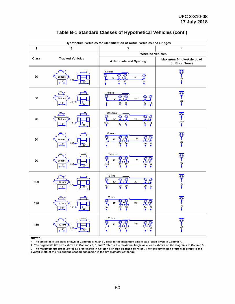
UFC 3-310-08 17 July 2018
50
Table B-1 Standard Classes of Hypothetical Vehicles (cont.)
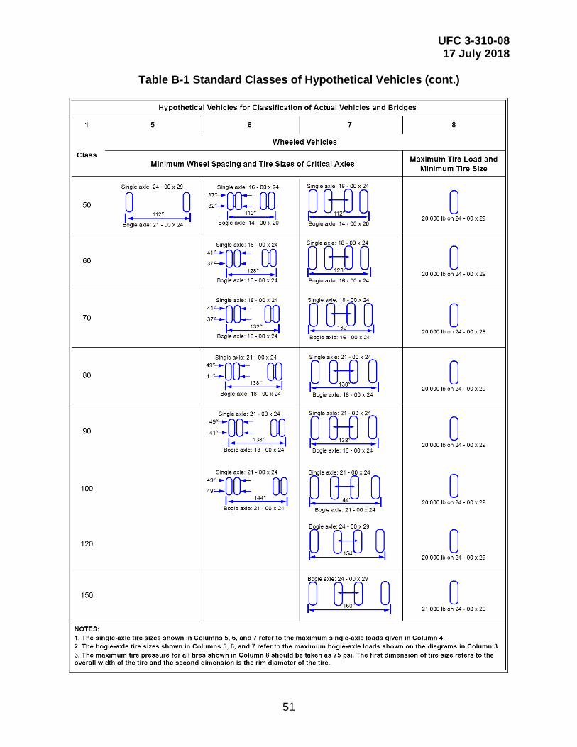
UFC 3-310-08 17 July 2018
51
Table B-1 Standard Classes of Hypothetical Vehicles (cont.)
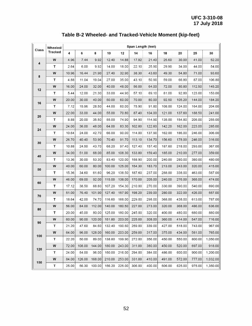
UFC 3-310-08 17 July 2018
52
Table B-2 Wheeled- and Tracked-Vehicle Moment (kip-feet)
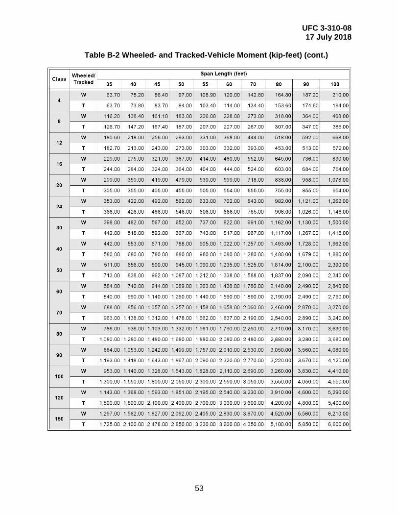
UFC 3-310-08 17 July 2018
53
Table B-2 Wheeled- and Tracked-Vehicle Moment (kip-feet) (cont.)
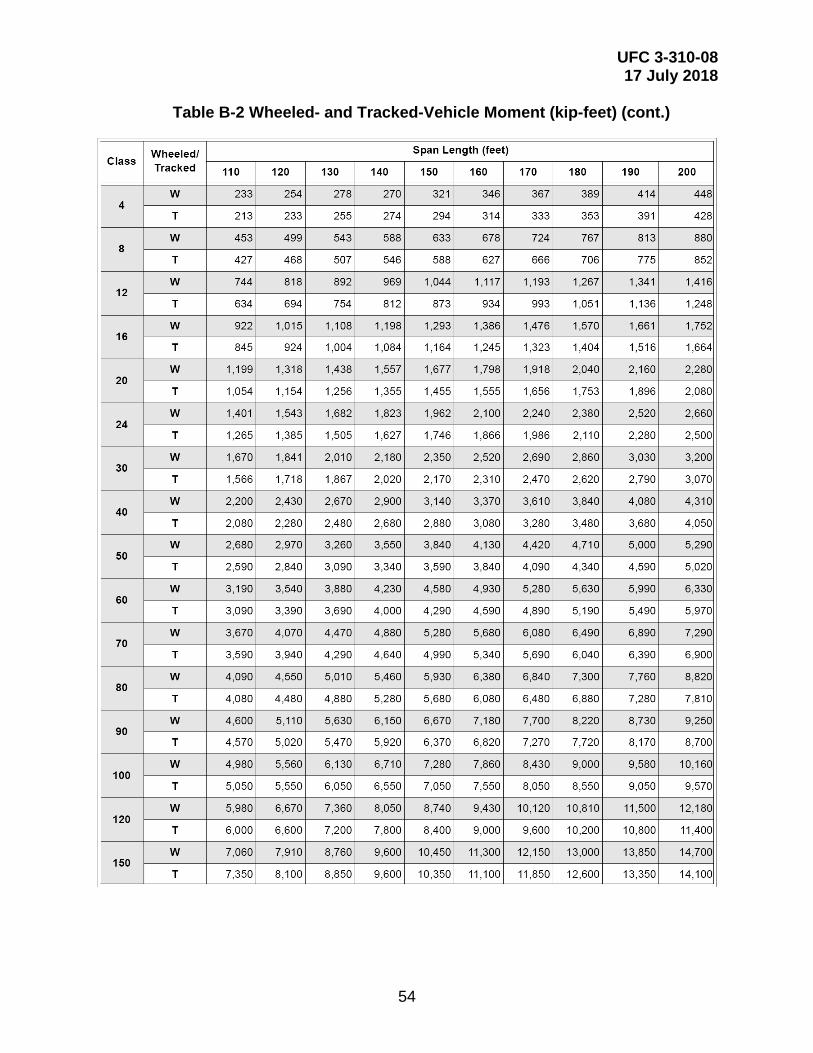
UFC 3-310-08 17 July 2018
54
Table B-2 Wheeled- and Tracked-Vehicle Moment (kip-feet) (cont.)
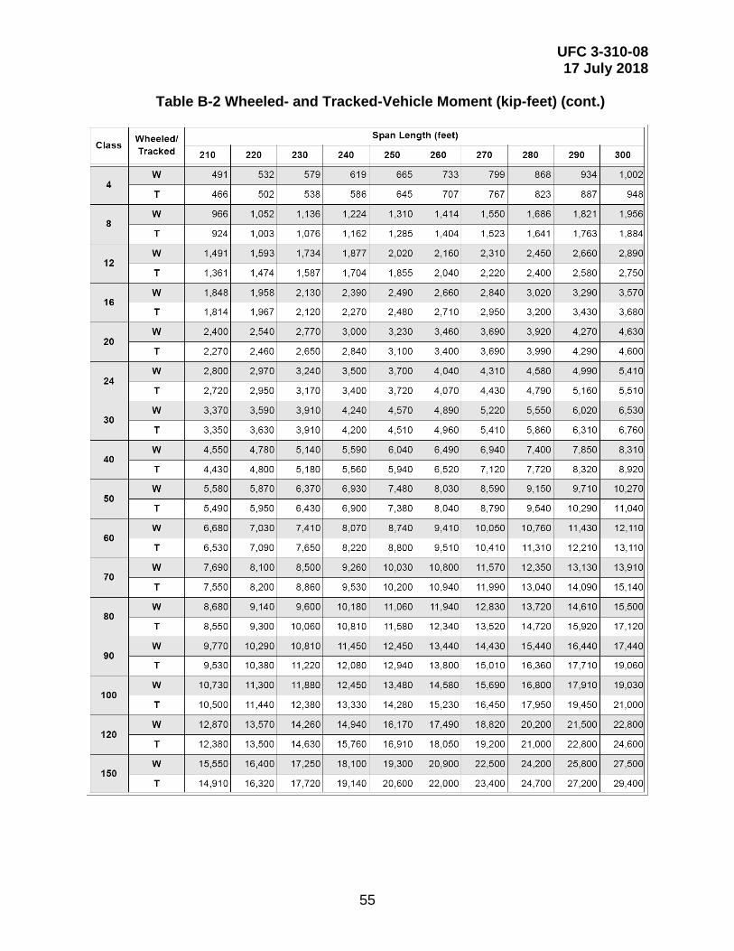
UFC 3-310-08 17 July 2018
55
Table B-2 Wheeled- and Tracked-Vehicle Moment (kip-feet) (cont.)
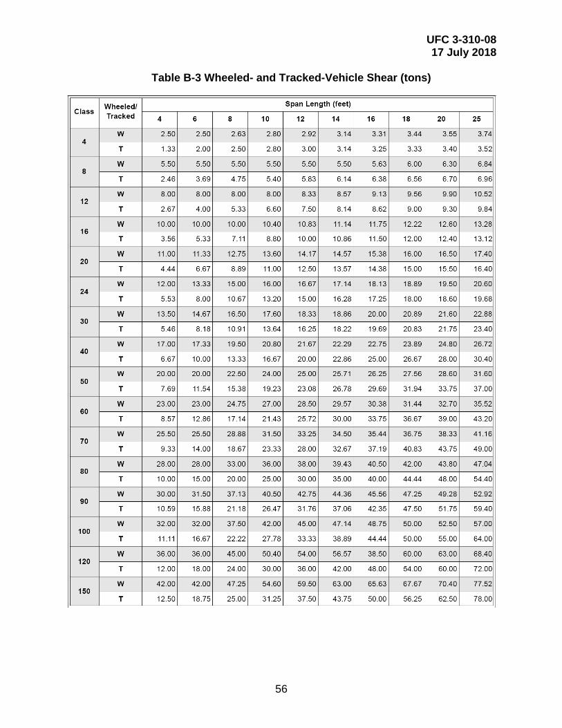
UFC 3-310-08 17 July 2018
56
Table B-3 Wheeled- and Tracked-Vehicle Shear (tons)
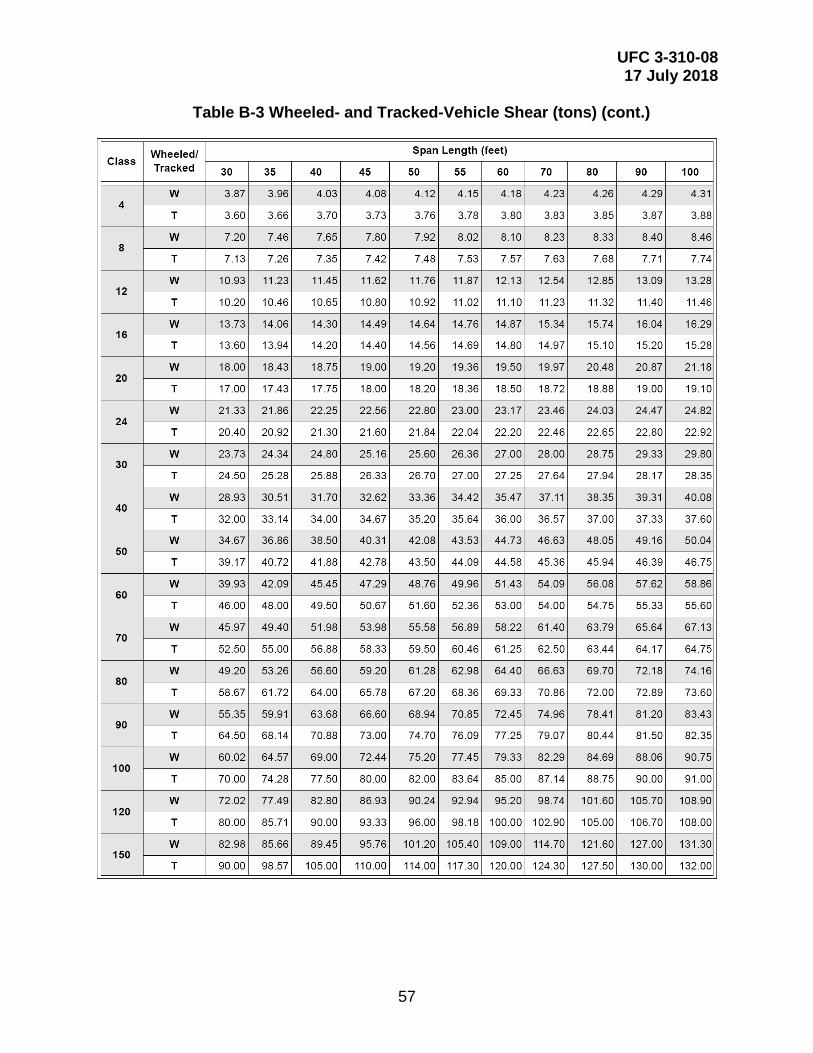
UFC 3-310-08 17 July 2018
57
Table B-3 Wheeled- and Tracked-Vehicle Shear (tons) (cont.)
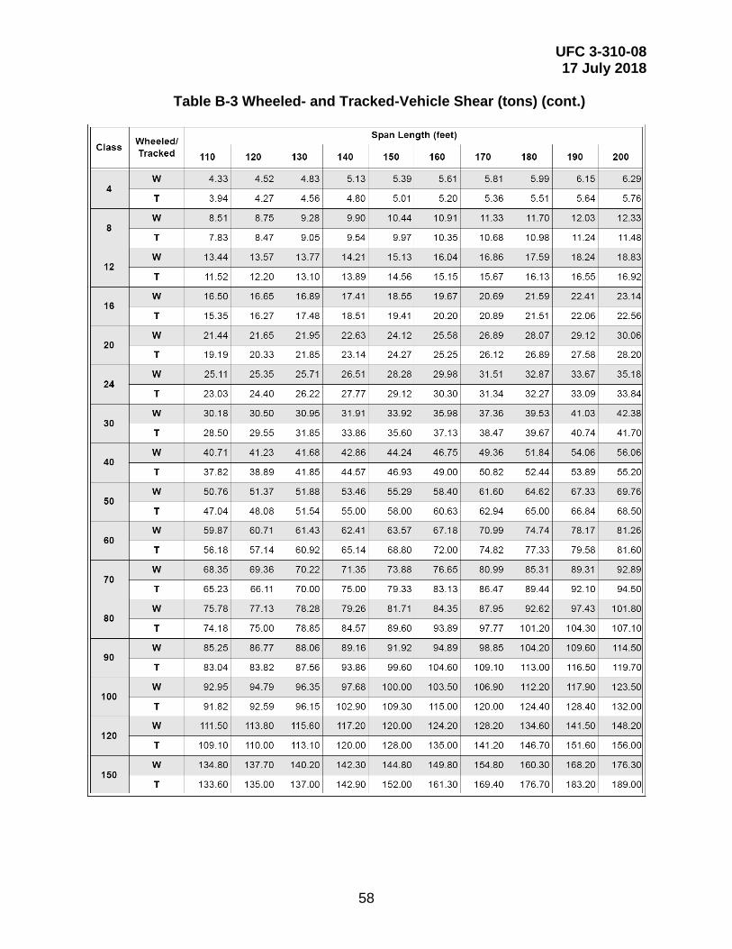
UFC 3-310-08 17 July 2018
58
Table B-3 Wheeled- and Tracked-Vehicle Shear (tons) (cont.)
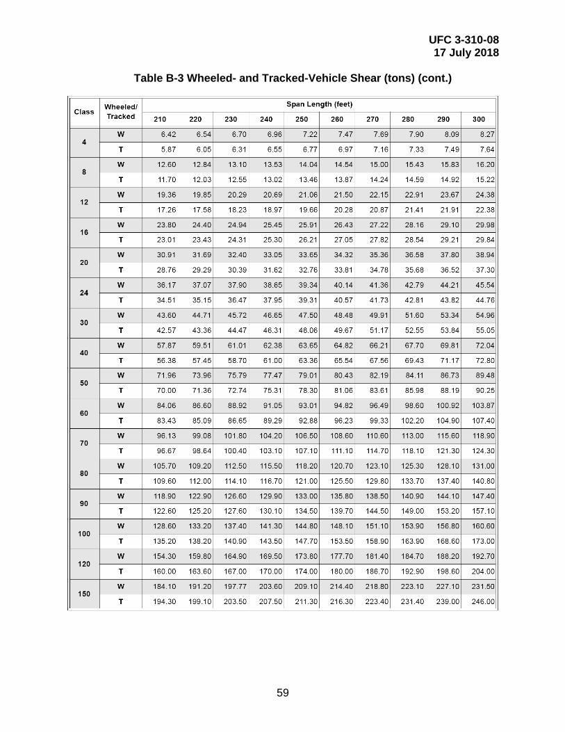
UFC 3-310-08 17 July 2018
59
Table B-3 Wheeled- and Tracked-Vehicle Shear (tons) (cont.)
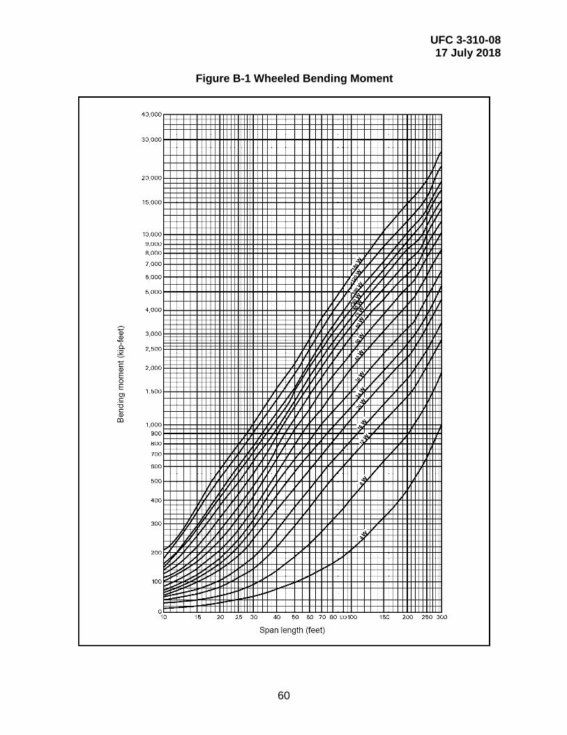
UFC 3-310-08 17 July 2018
60
Figure B-1 Wheeled Bending Moment
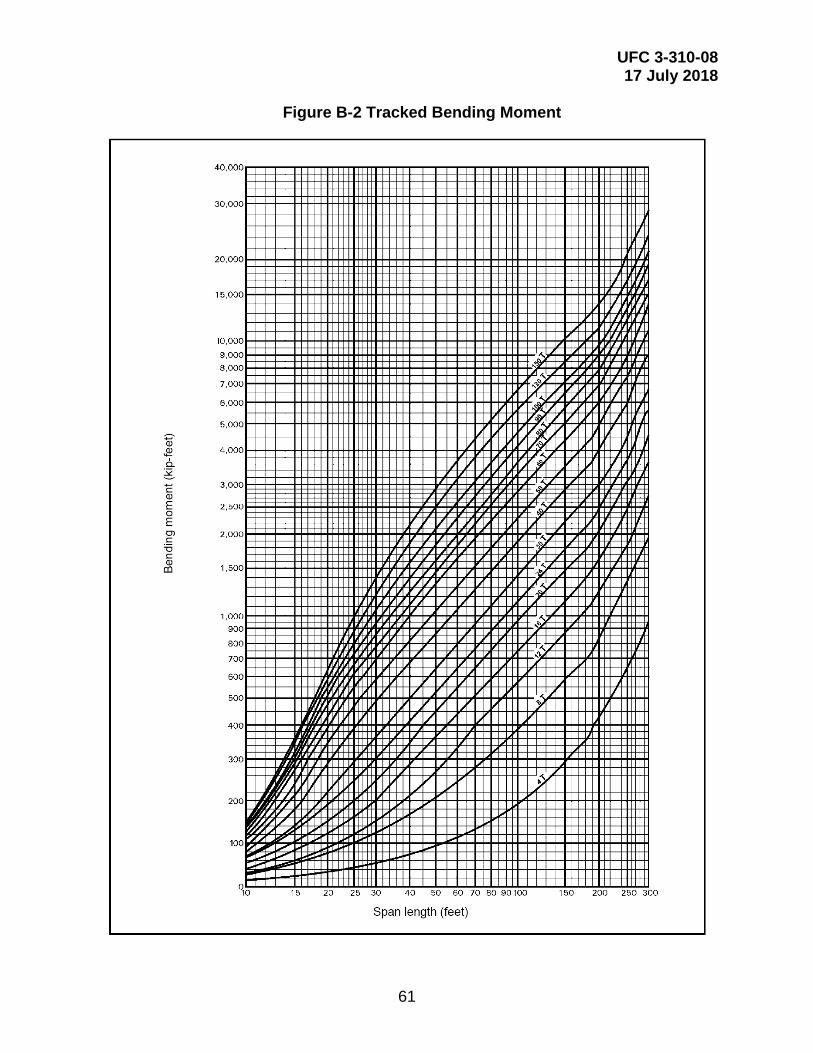
UFC 3-310-08 17 July 2018
61
Figure B-2 Tracked Bending Moment

UFC 3-310-08 17 July 2018
62
Figure B-3 Wheeled Shear
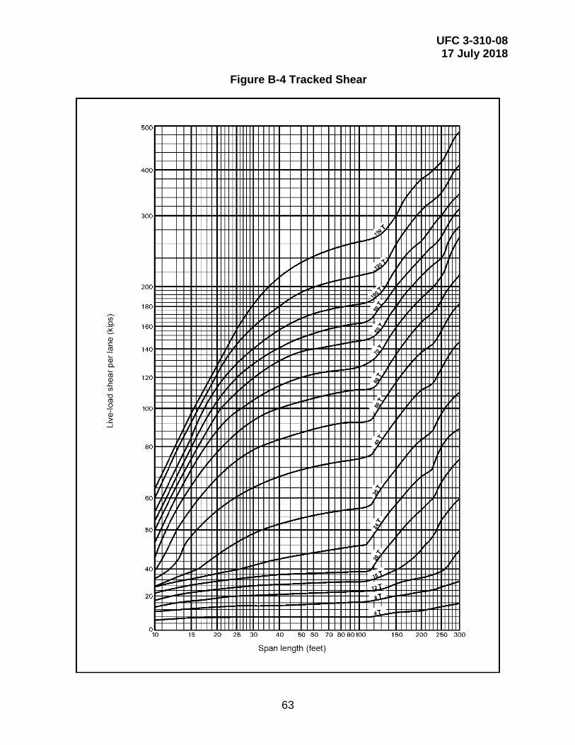
UFC 3-310-08 17 July 2018
63
Figure B-4 Tracked Shear
UFC 3-310-08 17 July 2018
64
B-2 CRITERIA FOR NATIONAL BRIDGE PROGRAM MANAGER TO ALTER INSPECTION INTERVAL.
The National Bridge Program Manager may alter the routine inspection interval for NBI highway bridges per the following criteria and procedures. It should be noted that the routine inspection interval may be either increased or decreased from the standard 24-month interval, although FHWA approval is only required for a decreased inspection interval.
Inspection intervals must be evaluated and, if necessary, adjusted after each inspection. Regardless of the interval selected for routine inspection, individual bridge members may require differing types and intervals of inspection (e.g., FCMs, distressed members, underwater members).
B-2.1 Procedure for FHWA Approval of Increased Inspection Intervals.
The National Bridge Program Manager will submit a request to increase the routine inspection interval to more than 24 months to the FHWA Eastern Federal Lands Highway Division (EFLHD). The FHWA will send approval of acceptance to the National Bridge Program Manager. Submissions to the FHWA for increased inspection intervals must contain the following information, at a minimum:
• The criteria used in establishing the interval between inspections, outlined above
• A discussion of failure experience, maintenance history, and latest inspection findings for the group of structures identified
• The proposed inspection interval
A template for requesting an extension of the inspection interval to 48 months for Service bridges that meet specific criteria is provided in paragraph B-2.2.

UFC 3-310-08 17 July 2018
65
B-2.2 Template for Requesting Increasing Bridge Inspection Interval to Four Years for Qualifying Bridges.
Mr. Hratch Pakhchanian, P.E. (or current EFLHD Bridge Engineer) Bridge Engineer Eastern Federal Lands Highway Division 21400 Ridgetop Circle, #341 Sterling, VA 20166 [email protected] (703) 404-6246 Subject: Submittal of Bureau of Reclamation's Criteria for Varying Bridge Inspection Frequency from Two-Year to a Four-Year Inspection Frequency Dear Mr. Pakhchanian: In accordance to the National Bridge Inspection Standards, Code of Federal Regulations, 23 Highways - Part 650, Subpart C, and Technical Advisory 5140.2 1 dated September 16, 1988, we hereby submit our application for increasing the two-year inspection interval for some of our structures to four years. See Attachment A for our criteria for increasing the bridge inspection interval. Should you have any questions regarding these criteria, please contact <insert name> at <insert phone number>, or email at <insert email address>. Sincerely, <insert signature block> Attachment A cc: Yohannes Mesfin (or current EFLHD Federal Agency Bridge Safety Engineer) Federal Agency Bridge Safety Engineer Eastern Federal Lands Highway Division 21400 Ridgetop Circle #341 Sterling, VA 20166 [email protected] (703) 404-6256

UFC 3-310-08 17 July 2018
66
ATTACHMENT A: CRITERIA FOR INCREASING <insert Military Department here> BRIDGE INSPECTION INTERVAL FROM TWO-YEAR TO A FOUR-YEAR INSPECTION FREQUENCY The <insert Military Department here> policy for increasing routine inspections inspection interval from the two-year requirement to four years on selected bridges is based on the general guidelines contained in Federal Highway Administration (FHWA) Technical Advisory, Revisions to the National Bridge Inspection Standards (NBIS), TA 5140.21. The <insert Military Department here> assessment is that the bridges selected for a decrease in routine inspection interval from the typical two-year inspection interval are in good to very good condition, will adhere to FHWA Technical Advisory 5140.21 Guidelines, and in addition meet the following criteria: All of the following criteria must be met before a bridge will be considered for an inspection interval greater than two years. Bridges eligible for increasing inspection interval from two years to a maximum of four years are: Bridges with condition ratings of 6 or greater. NBI 58, 59, 60, 61, and 62 ≥ 6. Bridges that have inventory ratings greater than or equal to the state’s legal load. NBI 66 ≥ HS20 (36 tons) or MS18 (32.4 metric tons) or HL-93 with a rating factor ≥ 1.0. Structures with length of maximum span (measured from center to center of bearing points) less than or equal to 100 feet. NBI 48 ≤ 100 feet (30.5 m). Structure types with load path redundancy. NBI 43B = 1, 2, 3, 4, 5, 6, 7, 11, 19. This rule applies to structures of all material types. No structure with fracture critical details will go on the extended policy, NBI 92A = N. Bridge Roadway Width, Curb to Curb is greater than or equal to 12 feet. NBI 51 ≥ 12.0 feet (3.66 m) Any vertical over or under clearances are greater than or equal to 14 feet. NBI 53 & 54 ≥ 14 feet (4.27 m). Structure is not susceptible to scour. NBI 113 > 4 and 113 ≠ 6. New bridge structures or newly rehabilitated structures must have received an inventory inspection and an in-depth inspection one or two years later. Any bridge considered for inspection intervals longer than two years must have received an in-depth inspection which revealed no major deficiencies.
UFC 3-310-08 17 July 2018
67
As a matter of policy, and in accordance with 23 Code of Federal Regulations (CFR) 650, National Bridge Inspection Standards (NBIS), the <insert Military Department here> inspects their bridges at two-year intervals and will continue to inspect most of our bridges at two-year intervals. Each <insert Military Department here> installation is responsible for inspecting bridges within their boundary; therefore, each Installation Bridge Manager in conjunction with the National Bridge Program Manager will determine which of the bridges located within their jurisdiction are eligible for an increased inspection interval of up to four years. Those structures that do not meet the criteria listed above are not eligible for increasing the inspection interval. Note: All references to National Bridge Inventory (NBI) items are those defined by FHWA-PD-96-001, Recording and Coding Guide for the Structure Inventory and Appraisal of the Nation’s Bridges, dated December 1995.
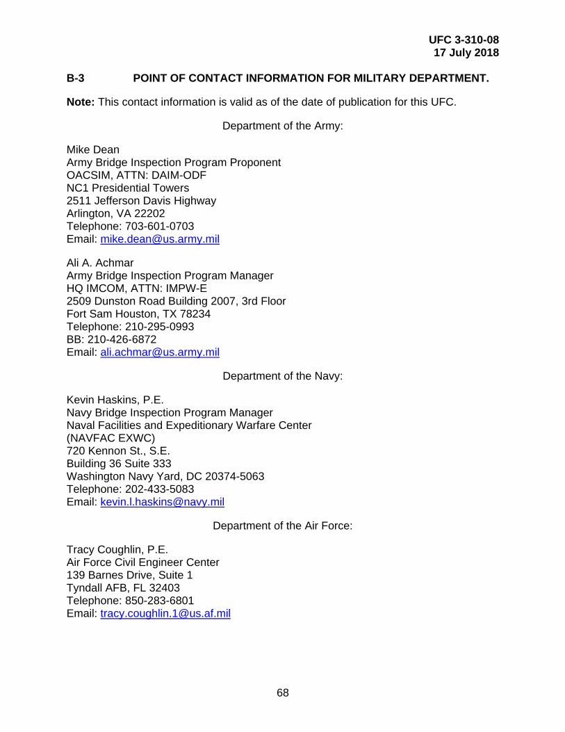
UFC 3-310-08 17 July 2018
68
B-3 POINT OF CONTACT INFORMATION FOR MILITARY DEPARTMENT.
Note: This contact information is valid as of the date of publication for this UFC.
Department of the Army:
Mike Dean Army Bridge Inspection Program Proponent OACSIM, ATTN: DAIM-ODF NC1 Presidential Towers 2511 Jefferson Davis Highway Arlington, VA 22202 Telephone: 703-601-0703 Email: [email protected]
Ali A. Achmar Army Bridge Inspection Program Manager HQ IMCOM, ATTN: IMPW-E 2509 Dunston Road Building 2007, 3rd Floor Fort Sam Houston, TX 78234 Telephone: 210-295-0993 BB: 210-426-6872 Email: [email protected]
Department of the Navy:
Kevin Haskins, P.E. Navy Bridge Inspection Program Manager Naval Facilities and Expeditionary Warfare Center (NAVFAC EXWC) 720 Kennon St., S.E. Building 36 Suite 333 Washington Navy Yard, DC 20374-5063 Telephone: 202-433-5083 Email: [email protected]
Department of the Air Force:
Tracy Coughlin, P.E. Air Force Civil Engineer Center 139 Barnes Drive, Suite 1 Tyndall AFB, FL 32403 Telephone: 850-283-6801 Email: [email protected]
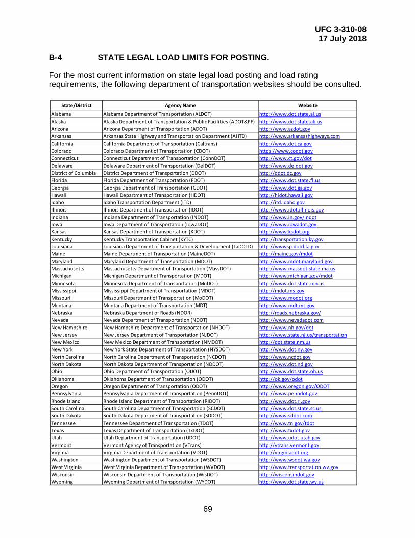
UFC 3-310-08 17 July 2018
69
B-4 STATE LEGAL LOAD LIMITS FOR POSTING.
For the most current information on state legal load posting and load rating requirements, the following department of transportation websites should be consulted.
State/District Agency Name Website
Alabama Alabama Department of Transportation (ALDOT) http://www.dot.state.al.usAlaska Alaska Department of Transportation & Public Facilities (ADOT&PF) http://www.dot.state.ak.usArizona Arizona Department of Transportation (ADOT) http://www.azdot.govArkansas Arkansas State Highway and Transportation Department (AHTD) http://www.arkansashighways.comCalifornia California Department of Transportation (Caltrans) http://www.dot.ca.govColorado Colorado Department of Transportation (CDOT) https://www.codot.govConnecticut Connecticut Department of Transportation (ConnDOT) http://www.ct.gov/dotDelaware Delaware Department of Transportation (DelDOT) http://www.deldot.govDistrict of Columbia District Department of Transportation (DDOT) http://ddot.dc.govFlorida Florida Department of Transportation (FDOT) http://www.dot.state.fl.usGeorgia Georgia Department of Transportation (GDOT) http://www.dot.ga.govHawaii Hawaii Department of Transportation (HDOT) http://hidot.hawaii.govIdaho Idaho Transportation Department (ITD) http://itd.idaho.govIllinois Illinois Department of Transportation (IDOT) http://www.idot.illinois.govIndiana Indiana Department of Transportation (INDOT) http://www.in.gov/indotIowa Iowa Department of Transportation (IowaDOT) http://www.iowadot.govKansas Kansas Department of Transportation (KDOT) http://www.ksdot.orgKentucky Kentucky Transportation Cabinet (KYTC) http://transportation.ky.govLouisiana Louisiana Department of Transportation & Development (LaDOTD) http://wwwsp.dotd.la.govMaine Maine Department of Transportation (MaineDOT) http://maine.gov/mdotMaryland Maryland Department of Transportation (MDOT) http://www.mdot.maryland.govMassachusetts Massachusetts Department of Transportation (MassDOT) http://www.massdot.state.ma.usMichigan Michigan Department of Transportation (MDOT) http://www.michigan.gov/mdotMinnesota Minnesota Department of Transportation (MnDOT) http://www.dot.state.mn.usMississippi Mississippi Department of Transportation (MDOT) http://mdot.ms.govMissouri Missouri Department of Transportation (MoDOT) http://www.modot.orgMontana Montana Department of Transportation (MDT) http://www.mdt.mt.govNebraska Nebraska Department of Roads (NDOR) http://roads.nebraska.gov/Nevada Nevada Department of Transportation (NDOT) http://www.nevadadot.comNew Hampshire New Hampshire Department of Transportation (NHDOT) http://www.nh.gov/dotNew Jersey New Jersey Department of Transportation (NJDOT) http://www.state.nj.us/transportationNew Mexico New Mexico Department of Transportation (NMDOT) http://dot.state.nm.usNew York New York State Department of Transportation (NYSDOT) http://www.dot.ny.govNorth Carolina North Carolina Department of Transportation (NCDOT) http://www.ncdot.govNorth Dakota North Dakota Department of Transportation (NDDOT) http://www.dot.nd.govOhio Ohio Department of Transportation (ODOT) http://www.dot.state.oh.usOklahoma Oklahoma Department of Transportation (ODOT) http://ok.gov/odotOregon Oregon Department of Transportation (ODOT) http://www.oregon.gov/ODOTPennsylvania Pennsylvania Department of Transportation (PennDOT) http://www.penndot.govRhode Island Rhode Island Department of Transportation (RIDOT) http://www.dot.ri.govSouth Carolina South Carolina Department of Transportation (SCDOT) http://www.dot.state.sc.usSouth Dakota South Dakota Department of Transportation (SDDOT) http://www.sddot.comTennessee Tennessee Department of Transportation (TDOT) http://www.tn.gov/tdotTexas Texas Department of Transportation (TxDOT) http://www.txdot.govUtah Utah Department of Transportation (UDOT) http://www.udot.utah.govVermont Vermont Agency of Transportation (VTrans) http://vtrans.vermont.govVirginia Virginia Department of Transportation (VDOT) http://virginiadot.orgWashington Washington Department of Transportation (WSDOT) http://www.wsdot.wa.govWest Virginia West Virginia Department of Transportation (WVDOT) http://www.transportation.wv.govWisconsin Wisconsin Department of Transportation (WisDOT) http://wisconsindot.govWyoming Wyoming Department of Transportation (WYDOT) http://www.dot.state.wy.us
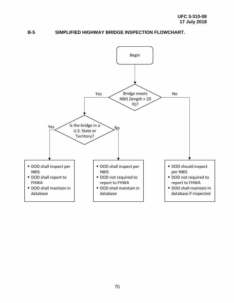
UFC 3-310-08 17 July 2018
70
B-5 SIMPLIFIED HIGHWAY BRIDGE INSPECTION FLOWCHART.
Begin
Bridge meets NBIS (length > 20
ft)?
Is the bridge in a U.S. State or
Territory?
DOD shall inspect per NBIS DOD shall report to
FHWA DOD shall maintain in
database
DOD shall inspect per NBIS DOD not required to
report to FHWA DOD shall maintain in
database
DOD should inspect per NBIS DOD not required to
report to FHWA DOD shall maintain in
database if inspected
Yes No
Yes No
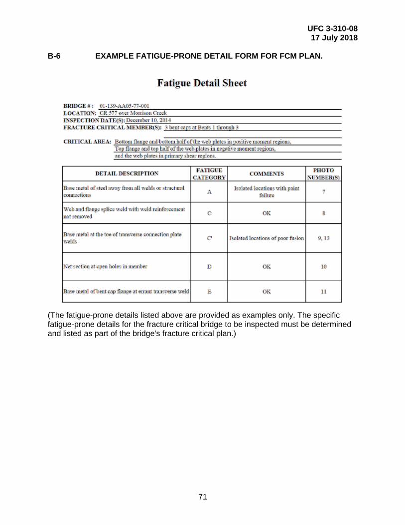
UFC 3-310-08 17 July 2018
71
B-6 EXAMPLE FATIGUE-PRONE DETAIL FORM FOR FCM PLAN.
(The fatigue-prone details listed above are provided as examples only. The specific fatigue-prone details for the fracture critical bridge to be inspected must be determined and listed as part of the bridge's fracture critical plan.)
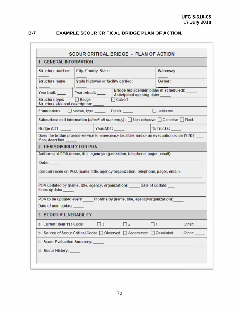
UFC 3-310-08 17 July 2018
72
B-7 EXAMPLE SCOUR CRITICAL BRIDGE PLAN OF ACTION.
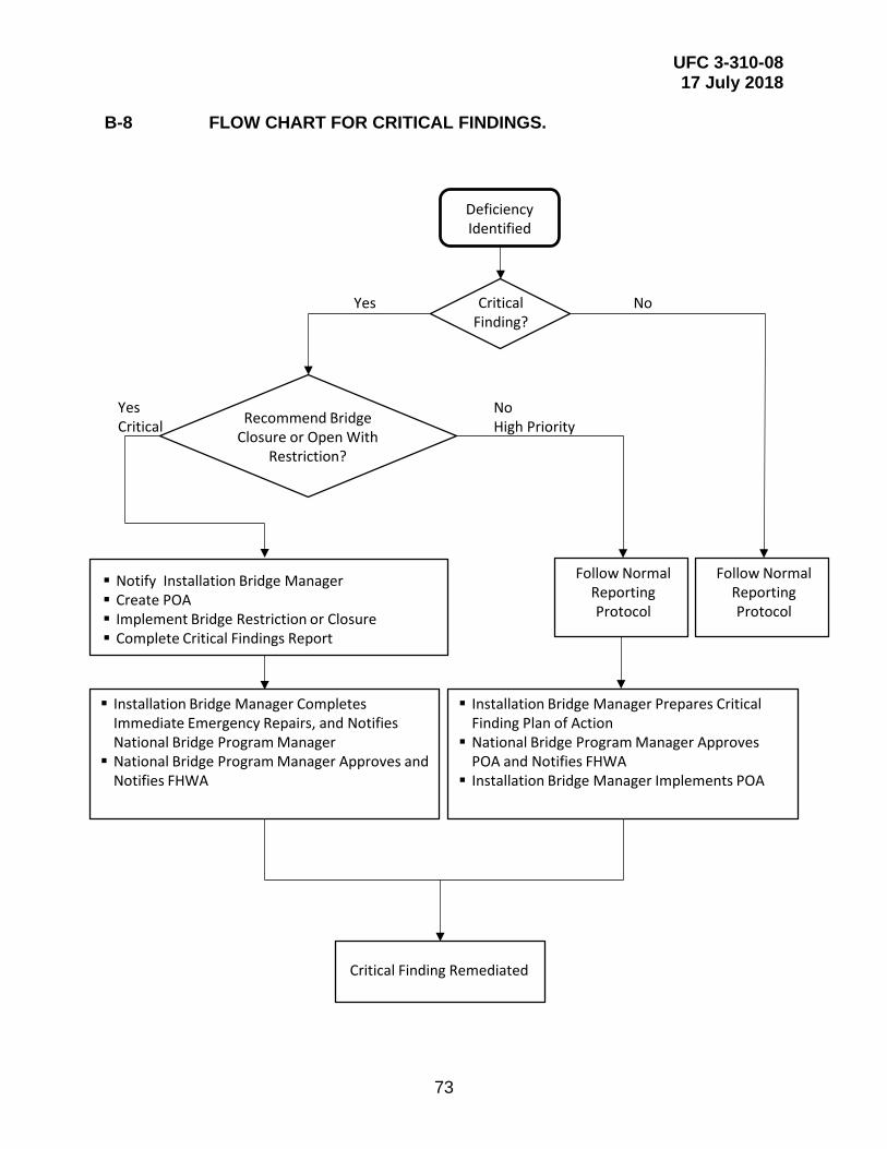
UFC 3-310-08 17 July 2018
73
B-8 FLOW CHART FOR CRITICAL FINDINGS.
Installation Bridge Manager Prepares Critical Finding Plan of Action National Bridge Program Manager Approves
POA and Notifies FHWA Installation Bridge Manager Implements POA
CriticalFinding?
Recommend Bridge Closure or Open With
Restriction?
Notify Installation Bridge Manager Create POA Implement Bridge Restriction or Closure Complete Critical Findings Report
Follow Normal Reporting Protocol
Critical Finding Remediated
Follow Normal Reporting Protocol
Yes No
YesCritical
NoHigh Priority
Installation Bridge Manager Completes Immediate Emergency Repairs, and Notifies National Bridge Program Manager National Bridge Program Manager Approves and
Notifies FHWA
DeficiencyIdentified

UFC 3-310-08 17 July 2018
74
B-9 EXAMPLE CRITICAL INSPECTION FINDING REPORT.
Bridge: Route: Installation: Country:
Inspector: Inspection Date: AADT:
Reason for Critical Inspection Finding Report (Be specific about deficiencies, attach photographs):
Inspector's Immediate Recommendations:
Immediate Closure Required Immediate Blocking/Shoring Required
Reduce Travelway Width (provide details):
Other:
Immediate Notification:
Plan of Action: Date:
Follow-up Actions: Completion Date:
CRITICAL INSPECTION FINDING REPORT
Installation Bridge Manager:
National Bridge Program Manager:
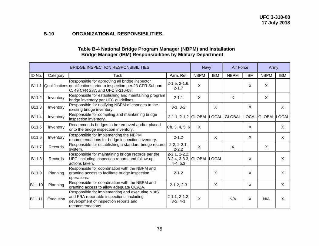
UFC 3-310-08 17 July 2018
75
B-10 ORGANIZATIONAL RESPONSIBILITIES.
Table B-4 National Bridge Program Manager (NBPM) and Installation Bridge Manager (IBM) Responsibilities by Military Department
BRIDGE INSPECTION RESPONSIBILITIES Navy Air Force Army
ID No. Category Task Para. Ref. NBPM IBM NBPM IBM NBPM IBM
B11.1 Qualifications Responsible for approving all bridge inspector qualifications prior to inspection per 23 CFR Subpart C, 49 CFR 237, and UFC 3-310-08.
2-1.5, 2-1.6, 2-1.7 X X X
B11.2 Inventory Responsible for establishing and maintaining program bridge inventory per UFC guidelines. 2-1.1 X X X
B11.3 Inventory Responsible for notifying NBPM of changes to the existing bridge inventory. 3-1, 3-2 X X X
B11.4 Inventory Responsible for compiling and maintaining bridge inspection inventory. 2-1.1, 2-1.2 GLOBAL LOCAL GLOBAL LOCAL GLOBAL LOCAL
B11.5 Inventory Recommends bridges to be removed and/or placed onto the bridge inspection inventory. Ch. 3, 4, 5, 6 X X X
B11.6 Inventory Responsible for implementing the NBPM recommendations for bridge inspection inventory. 2-1.2 X X X
B11.7 Records Responsible for establishing a standard bridge records system.
2-2, 2-2.1, 2-2.2 X X X
B11.8 Records Responsible for maintaining bridge records per the UFC, including inspection reports and follow-up actions taken.
2-2.1, 2-2.2, 3-2.4, 3-3.3,
4-4, 5.3 GLOBAL LOCAL X X
B11.9 Planning Responsible for coordination with the NBPM and granting access to facilitate bridge inspection operations.
2-1.2 X X X
B11.10 Planning Responsible for coordination with the NBPM and granting access to allow adequate QC/QA. 2-1.2, 2-3 X X X
B11.11 Execution
Responsible for implementing and executing NBIS and FRA reportable inspections, including development of inspection reports and recommendations.
2-1.1, 2-1.2, 3-2, 4-1 X N/A X N/A X
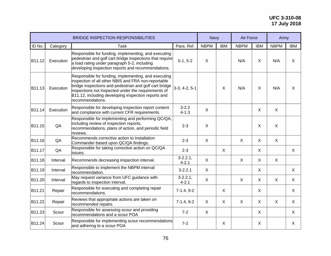
UFC 3-310-08 17 July 2018
76
BRIDGE INSPECTION RESPONSIBILITIES Navy Air Force Army
ID No. Category Task Para. Ref. NBPM IBM NBPM IBM NBPM IBM
B11.12 Execution
Responsible for funding, implementing, and executing pedestrian and golf cart bridge inspections that require a load rating under paragraph 5-2, including developing inspection reports and recommendations.
5-1, 5-2 X N/A X N/A X
B11.13 Execution
Responsible for funding, implementing, and executing inspection of all other NBIS and FRA non-reportable bridge inspections and pedestrian and golf cart bridge inspections not inspected under the requirements of B11.12, including developing inspection reports and recommendations.
3-3, 4-2, 5-1 X N/A X N/A X
B11.14 Execution Responsible for developing inspection report content and compliance with current CFR requirements.
3-2.2 4-1.3 X X X
B11.15 QA
Responsible for implementing and performing QC/QA, including review of inspection reports, recommendations, plans of action, and periodic field reviews.
2-3 X X X
B11.16 QA Recommends corrective action to Installation Commander based upon QC/QA findings. 2-3 X X X X
B11.17 QA Responsible for taking corrective action on QC/QA issues. 2-3 X X X
B11.18 Interval Recommends decreasing inspection interval. 3-2.2.1, 4-2.1 X X X X
B11.19 Interval Responsible to implement the NBPM interval recommendation. 3-2.2.1 X X X
B11.20 Interval May request variance from UFC guidance with regards to inspection interval.
3-2.2.1, 4-2.1 X X X X X
B11.21 Repair Responsible for executing and completing repair recommendations. 7-1.4, 9-2 X X X
B11.22 Repair Reviews that appropriate actions are taken on recommended repairs. 7-1.4, 9-2 X X X X X X
B11.23 Scour Responsible for assessing scour and providing recommendations and a scour POA 7-2 X X X
B11.24 Scour Responsible for implementing scour recommendations and adhering to a scour POA 7-2 X X X
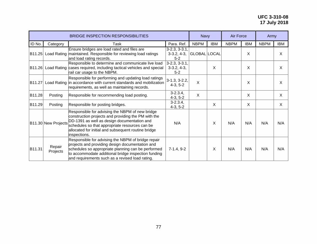
UFC 3-310-08 17 July 2018
77
BRIDGE INSPECTION RESPONSIBILITIES Navy Air Force Army
ID No. Category Task Para. Ref. NBPM IBM NBPM IBM NBPM IBM
B11.25 Load Rating Ensure bridges are load rated and files are maintained. Responsible for reviewing load ratings and load rating records.
3-2.3, 3-3.1, 3-3.2, 4-3,
5-2 GLOBAL LOCAL X X
B11.26 Load Rating Responsible to determine and communicate live load cases required, including tactical vehicles and special rail car usage to the NBPM.
3-2.3, 3-3.1, 3-3.2, 4-3,
5-2 X X X
B11.27 Load Rating Responsible for performing and updating load ratings in accordance with current standards and mobilization requirements, as well as maintaining records.
3-1.3, 3-2.2, 4-3, 5-2 X X X
B11.28 Posting Responsible for recommending load posting. 3-2.3.4, 4-3, 5-2 X X X
B11.29 Posting Responsible for posting bridges. 3-2.3.4, 4-3, 5-2 X X X
B11.30 New Projects
Responsible for advising the NBPM of new bridge construction projects and providing the PM with the DD-1391 as well as design documentation and schedules so that appropriate resources can be allocated for initial and subsequent routine bridge inspections.
N/A X N/A N/A N/A N/A
B11.31 Repair Projects
Responsible for advising the NBPM of bridge repair projects and providing design documentation and schedules so appropriate planning can be performed to accommodate additional bridge inspection funding and requirements such as a revised load rating.
7-1.4, 9-2 X N/A N/A N/A N/A

UFC 3-310-08 17 July 2018
78
This Page Intentionally Left Blank

UFC 3-310-08 17 July 2018
79
APPENDIX C GLOSSARY
AAR—Association of American Railroads
AASHTO— American Association of State Highway and Transportation Officials
ACI—American Concrete Institute
AREMA—American Railway Engineering and Maintenance-of-Way Association
BIRM—FHWA Bridge Inspector’s Reference Manual
CFR—Code of Federal Regulations
CONUS—Continental United States
DD 1391—FY ___ Military Construction Project Data
DOD—Department of Defense
EM—Army Engineering Manual
FCM—fracture critical member
FHWA EFLHD—Federal Highway Administration, Eastern Federal Lands Highway Division
FHWA—Federal Highway Administration
FM—Army Field Manual
FRA—Federal Railway Administration
IBM—Installation Bridge Manager
LRFD—Load and resistance factor design
MLC—military load classification
MUTCD—AASHTO Manual on Uniform Traffic Control Devices for Streets and Highways
NBI—National Bridge Inventory
NBIS—National Bridge Inspection Standards
NBPM—National Bridge Program Manager
NDT—nondestructive techniques
UFC 3-310-08 17 July 2018
80
OCONUS—Outside Continental United States
PDT—partially destructive techniques
P.E.—Professional Engineer
POA—Plan of Action
psf—pound per square foot
QA—quality assurance
QC—quality control
SI&A—Structure Inventory and Appraisal
STANAG—Standardization Agreement
STRAHNET—Strategic Highway Corridor Network
TM—Army Technical Manual
UFC—Unified Facilities Criteria
USC—United States Code