underwater gps user manual - water...
TRANSCRIPT

Underwater GPSUser Manual
Document number
W-DN-17002-3
Project
-
Classification
-
Rev Date Prepared by Checked by Approved by Short description
1 2017-08-03 T. Trøite O. Skisland T. Trøite Initial
2 2017-08-04 T. Trøite O. Skisland T. Trøite Minor changes
3 2017-12-19 E. Thorbjørnsen T. Trøite T. Trøite 1.4 SW release
References
[1] : Water Linked, W-MK-17020 Underwater GPS Developer Kit Datasheet
[2] : Water Linked, W-MK-17022 Receiver-D1 Datasheet
[3] : Water Linked, W-MK-17023 Locator-A1 Datasheet
[4] : Water Linked, W-MK-17024 Locator-D1 Datasheet
[5] : Water Linked, W-MK-17025 Master-D1 Datasheet
[6] : Water Linked, waterlinked.com
___________________________________________________________________________________________________________________________________________________________
Title User Manual Class. - Date 2017-12-19Number W-DN-17002-3 Author E. Thorbjørnsen Page 1 of 22

Table of Contents WARNINGS..................................................................................................................................................... 3 1 Introduction................................................................................................................................................... 4 2 General......................................................................................................................................................... 5
2.1 Kit content............................................................................................................................................. 5 2.2 Connectors........................................................................................................................................... 6 2.3 Master-D1 Electronics........................................................................................................................... 6
3 Hardware Setup............................................................................................................................................ 7 3.1 Network................................................................................................................................................. 7 3.2 Acoustics............................................................................................................................................... 7 3.3 Power.................................................................................................................................................... 8 3.4 Locators................................................................................................................................................ 9 3.5 Reference Systems.............................................................................................................................. 9 3.6 Guidelines........................................................................................................................................... 11 3.7 Boat Example..................................................................................................................................... 12 3.8 GPS.................................................................................................................................................... 12
3.8.1 GPS-antenna assembly..............................................................................................................13 3.9 IMU..................................................................................................................................................... 13
3.9.1 IMU Calibration........................................................................................................................... 13 4 Software...................................................................................................................................................... 14
4.1 Signal flow.......................................................................................................................................... 14 4.2 Architecture......................................................................................................................................... 15 4.3 GUI..................................................................................................................................................... 16
4.3.1 Configuration page.....................................................................................................................16 4.4 API...................................................................................................................................................... 17 4.5 SW update.......................................................................................................................................... 18
5 Specifications.............................................................................................................................................. 19 5.1 Dimensions......................................................................................................................................... 19 5.2 D1 interface........................................................................................................................................ 20 5.3 A1 interface......................................................................................................................................... 20
6 Diagnostics................................................................................................................................................. 21 6.1 D1 interface........................................................................................................................................ 21 6.2 WEB diagnostics................................................................................................................................. 21 6.3 Interference......................................................................................................................................... 22
7 Helpful links................................................................................................................................................ 22
___________________________________________________________________________________________________________________________________________________________
Title User Manual Class. - Date 2017-12-19Number W-DN-17002-3 Author E. Thorbjørnsen Page 2 of 22

WARNINGS
To avoid the risk of damage to the Underwater GPS, please read this user manual carefully before it is installed and used for the first time.
Operation area The Underwater GPS ONLY work in water. It dose not work in air.
Max voltage The absolute maximum voltage rating of the equipment is 18V. Voltages above this will damage the electronics.
Reverse voltage The board does not have reverse polarity protection. Do not apply a negative voltage to red power wire since this will damage the electronics.
Temperature Make sure the system does not overheat. Avoid placing in direct sunlight over extended periods of time.
Hot swapping The Receiver-D1 and Locator-D1 shall not be hot-swapped. Make sure to power off the system before connecting the Locator-D1 or Receiver-D1 cables.
Salt water The Master-D1 Electronics will quickly corrode if it comes in contact with salt water. Keep the housing lid closed when in the field to avoid salt water to get in contact with any electronics.
Force Avoid using excessive force on connectors, screws and other parts of the system since this can lead to mechanical damage.
___________________________________________________________________________________________________________________________________________________________
Title User Manual Class. - Date 2017-12-19Number W-DN-17002-3 Author E. Thorbjørnsen Page 3 of 22

1 Introduction
The Underwater GPS is a robust and reliable acoustic positioning system with a range of 100m. The purposeof the system is to give a live GPS position of ROVs, surface-supplied divers and other moving objects belowthe water surface.
The Underwater GPS system is based on Short Baseline (SBL) acoustic positioning. The Locator is placed on a ROV or diver and functions as a beacon that sends out an acoustic pulse. Near the surface, there are four receiver hydrophones lowered into the water. The receivers listen for the pulse from the locator. Time-of-arrival to each receiver is used to calculate the Locator’s position. SBL systems, compared to the USBL systems, have the advantage of working well in shallow water and noisy acoustic environments, such as in a fish cage.
Once the position is known relative to the receivers, the global position can be found by adding that to the position obtained by a GPS receiver. The Underwater GPS system does that part internally so that it can provide the actual global position of the ROV as it's output.
___________________________________________________________________________________________________________________________________________________________
Title User Manual Class. - Date 2017-12-19Number W-DN-17002-3 Author E. Thorbjørnsen Page 4 of 22
Illustration 1: Screenshot of master and ROV position

2 General
2.1 Kit content
Qty Part number Name Image
1 WL-11001Underwater GPS Housing with Master-D1 electronics
4 WL-21005 Receiver-D1 with 10m cable
(1) WL-21009Locator-A1 with 1m cable andno connector
(1) WL-21016Locator-D1 with 100m cable. The Locator-D1 does not come as standard.
1 3m Ethernet cable
1 3m power cable
1 External GPS antenna
___________________________________________________________________________________________________________________________________________________________
Title User Manual Class. - Date 2017-12-19Number W-DN-17002-3 Author E. Thorbjørnsen Page 5 of 22

2.2 Connectors
2.3 Master-D1 Electronics
___________________________________________________________________________________________________________________________________________________________
Title User Manual Class. - Date 2017-12-19Number W-DN-17002-3 Author E. Thorbjørnsen Page 6 of 22

3 Hardware Setup
3.1 Network
At power-up, the Master-D1 reads the DIP-switch settings. The network mode depends on the GP0 and GP1position.
GP0 GP1 Network mode DHCP client example mode
ON ON DHCP client
OFF ON Static IP 192.168.2.94
ON OFF Static IP 10.11.12.94
OFF OFF DHCP Server, 192.168.0.1
The BS0 and BS1 positions on the dip switch shall both be ON. These boot-select pins are used in factory programming only.
Use the supplied Ethernet cable to connect the Underwater GPS to a network switch or directly into the host computer.
3.2 Acoustics
• Connect the four Receiver-D1 cables to channel 1 to 4 on the housing, ref chapter 2.2
• If using the Locator-D1, connect this to the D1 connector on the housing, ref chapter 2.2
• If using the Locator-A1, connect this to the A1 connector on the housing, ref chapter 2.2
___________________________________________________________________________________________________________________________________________________________
Title User Manual Class. - Date 2017-12-19Number W-DN-17002-3 Author E. Thorbjørnsen Page 7 of 22

3.3 Power
The power cable comes with stripped jacket. Connect the stripped cables to your favorite 12V power source.
Black : Negative
Red : Positive
Voltage : 10 – 18V
Current : 0.7A (12V nominal)
___________________________________________________________________________________________________________________________________________________________
Title User Manual Class. - Date 2017-12-19Number W-DN-17002-3 Author E. Thorbjørnsen Page 8 of 22

3.4 Locators
The Underwater GPS can be used with two different types of Locators, Locator-A1 and Locator-D1. The Locator-A1 is recommended when integrating on ROVs. See comparison table bellow.
Parameter Locator-D1 Locator-A1
Technology Digital Analog
Intended use Retrofit ROV or compressed diving Full ROV integration
Signal 3x twisted pair (RX, TX and power) 1x twisted pair (TX)
Cable length Max 100m Max 300m
Depth sensor Integrated No depth sensor. The ROV control system must write the ROV depth using the API to the Master-D1 electronics.
Block diagram
Picture
3.5 Reference Systems
In order to calculate the absolute position of the Locator we need to define two reference systems, the acoustic and the global reference system. The global reference system is defined by latitude and longitude and is the reference system used by the GPS and in maps.
___________________________________________________________________________________________________________________________________________________________
Title User Manual Class. - Date 2017-12-19Number W-DN-17002-3 Author E. Thorbjørnsen Page 9 of 22

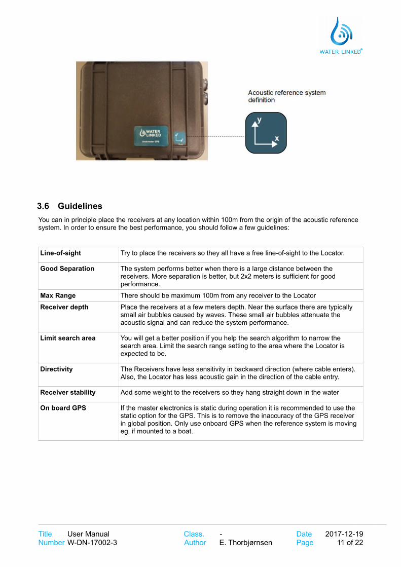
The acoustic reference system (the x and y axis) is defined by the orientation of the housing. The housing is by definition located in origin (x=0, y=0). A label on top of the lid indicates the x-y coordinate system. The position of the receivers and the search area are specified in the Acoustic reference system.
___________________________________________________________________________________________________________________________________________________________
Title User Manual Class. - Date 2017-12-19Number W-DN-17002-3 Author E. Thorbjørnsen Page 10 of 22
3.6 Guidelines
You can in principle place the receivers at any location within 100m from the origin of the acoustic reference system. In order to ensure the best performance, you should follow a few guidelines:
Line-of-sight Try to place the receivers so they all have a free line-of-sight to the Locator.
Good Separation The system performs better when there is a large distance between the receivers. More separation is better, but 2x2 meters is sufficient for good performance.
Max Range There should be maximum 100m from any receiver to the Locator
Receiver depth Place the receivers at a few meters depth. Near the surface there are typically small air bubbles caused by waves. These small air bubbles attenuate the acoustic signal and can reduce the system performance.
Limit search area You will get a better position if you help the search algorithm to narrow the search area. Limit the search range setting to the area where the Locator is expected to be.
Directivity The Receivers have less sensitivity in backward direction (where cable enters). Also, the Locator has less acoustic gain in the direction of the cable entry.
Receiver stability Add some weight to the receivers so they hang straight down in the water
On board GPS If the master electronics is static during operation it is recommended to use the static option for the GPS. This is to remove the inaccuracy of the GPS receiver in global position. Only use onboard GPS when the reference system is moving eg. if mounted to a boat.
___________________________________________________________________________________________________________________________________________________________
Title User Manual Class. - Date 2017-12-19Number W-DN-17002-3 Author E. Thorbjørnsen Page 11 of 22

3.7 Boat Example
The illustration bellow shows a typical receiver configuration when installed on a boat. The receivers are hanging from the side of the boat, one in each corner. The depth of the receivers are typically 2-4m, deep enough to get below the hull and get free line-of-sight to the Locator. Notice how the housing defines the origin and coordinate system of the acoustic reference system.
3.8 GPS
The on-board GPS module is used to position the system in a global reference system. An external antenna with integrated amplifier is used to improve GPS reception. The signal strength of the GPS can be seen on the top bar in the web GUI.
___________________________________________________________________________________________________________________________________________________________
Title User Manual Class. - Date 2017-12-19Number W-DN-17002-3 Author E. Thorbjørnsen Page 12 of 22

3.8.1 GPS-antenna assemblyThe GPS-antenna can be mounted anywhere you want, but remember the GPS-antenna is the origin of the master electronics position. Therefor it is recommended to fasten the antenna on the lid of the pelican case. With the 3M double sided tape, attach the GPS- antenna to the lid of the pelican case.
Connect the GPS-antenna cable to the SMA connector on the master electronics. Torque the SMA nut to 3–5in·lbf (0.3 to 0.6 N·m) or slightly more than finger tight.
3.9 IMU
The master electronics has an built in IMU used to provide the orientation of the master electronics. This is used in combination with the acoustic position and GPS to generate the global position of the Locator.
3.9.1 IMU CalibrationFor the IMU to work properly it needs to be calibrated. The calibration data is stored when full calibration is obtained for faster calibration on restart of the system. If the system is started on a new location a new calibration is needed for the IMU to work as intended.
To calibrate the IMU disconnect all Recivers and Locator cables, but leave power and Ethernet connected. While looking at the top bar in the web GUI on the IMU status bar move the pelican case in a figure of 8 until all the bars are green.
___________________________________________________________________________________________________________________________________________________________
Title User Manual Class. - Date 2017-12-19Number W-DN-17002-3 Author E. Thorbjørnsen Page 13 of 22

4 Software
4.1 Signal flow
The diagram below shows the major signal processing blocks and how they are connected.
___________________________________________________________________________________________________________________________________________________________
Title User Manual Class. - Date 2017-12-19Number W-DN-17002-3 Author E. Thorbjørnsen Page 14 of 22

4.2 Architecture
The block diagram below shows how the Web GUI and API are interconnected with the rest of the internal system.
___________________________________________________________________________________________________________________________________________________________
Title User Manual Class. - Date 2017-12-19Number W-DN-17002-3 Author E. Thorbjørnsen Page 15 of 22
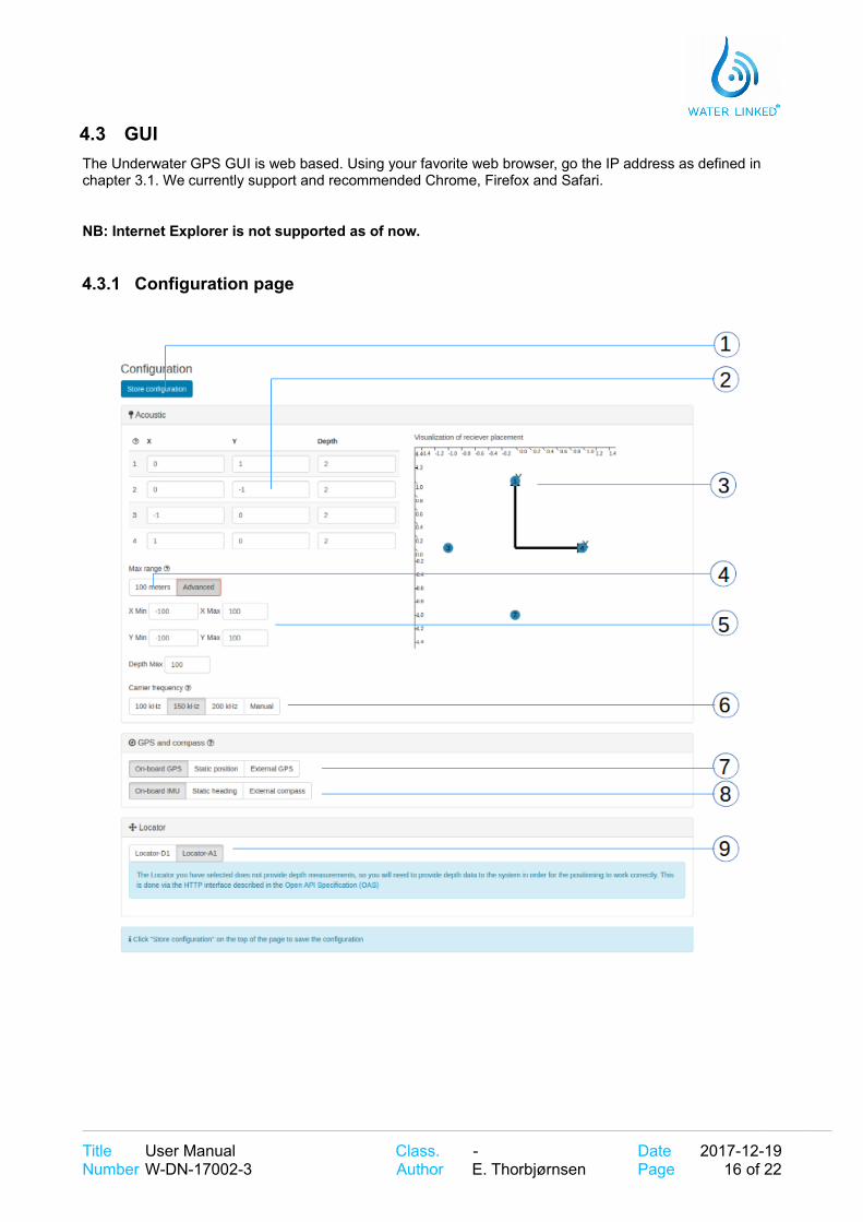
4.3 GUI
The Underwater GPS GUI is web based. Using your favorite web browser, go the IP address as defined in chapter 3.1. We currently support and recommended Chrome, Firefox and Safari.
NB: Internet Explorer is not supported as of now.
4.3.1 Configuration page
___________________________________________________________________________________________________________________________________________________________
Title User Manual Class. - Date 2017-12-19Number W-DN-17002-3 Author E. Thorbjørnsen Page 16 of 22

# Description API
1 The system configuration is stored on the server. Press “Store configuration” to save current configuration. The current setting are automatically loaded when the page is opened.
2 Configuration of the receiver position. Set the coordinates (x,y,depth) of all four receivers [meters]. The depth is always a positive number.
/config/receivers
3 The visualization sector gives a graphical representation of the receiver positions. This makes it easier to verify that the configuration is correct.
4 This button sets search area to ± 100m
5 Configuration of the active search range. Set the maximum/minimum of the x and y search area. To improve the quality of the position estimation it is a good idea to define a small search area and leave out “impossible” position sectors.
/config/generic
6 Setting of the acoustic frequency. This can be used in case other acoustic devices operate in the area, like sonars, echo sounders and modems. In case of interference, change the carrier frequency.
/config/generic
7 Configuration of the master (housing) position. This configuration selects how to map the two reference systems, the Global and the Acoustic reference system. There are three sources of this
• On-board GPS. With this setting the global position of the master is based on the on-board GPS.
• Static. The latitude and longitude are static numbers and configured directly in GUI.
• External. The GPS position in provided through the API, typically from the boat navigation system.
8 Configuration of the orientation of the master.There are three sources of this
• On-board IMU. With this setting the orientation of the master is based on the on-board IMU.
• Static. The heading of the master is static. The heading is configured directly in GUI.
• External. The heading is provided through the API, typically from the boat navigation system or compass.
9 Locator selection. When using Locator-A1, the depth must be written to the system. This is done via the HTTP interface described in the Open API Specification (OAS)
4.4 API
The Underwater GPS comes with an easy-to-use API. This API uses a HTTP-based scheme to interact with the system. Through the API the user can among others
• set configuration settings
• read acoustic and global position data
• read GPS and IMU raw data
SWAGGER is used for API documentation. See demo.waterlinked.com/swagger for more information.
___________________________________________________________________________________________________________________________________________________________
Title User Manual Class. - Date 2017-12-19Number W-DN-17002-3 Author E. Thorbjørnsen Page 17 of 22

4.5 SW update
A SW update package (.wlup) includes all files required to update the system. Some SW updates also requires an update of the low-level FPGA image. The FPGA image is encrypted with a unique key. To generate a new FPGA image for your board, Water Linked needs to know the Chip ID of your bard. The ChipID can be found in the About tab of the GUI. To get the latest software package for your kit, go to update.waterlinked.com and enter the Chip ID of your kit.
Step Instruction Ref
1 Power off the system
2 Set Master-D1 to fixed IP “192.168.2.94” See chapter 3.1
3 Set the IP on your own computer to be on the same sub-net
4 Power up the system while at the same time keeping the GP0 pin on the GPIO connector grounded
5 Go to web GUI http://192.168.2.94
6 After the system has booted and you see the upgrader GUI, remove the grounding of GP0.
7 Click “Browse file” and select correct <>.wlup file
8 Wait for update process to complete
9 When the update process is complete and successful,the system will automatically reboot to standard mode
10 Verify that the SW version has updated
___________________________________________________________________________________________________________________________________________________________
Title User Manual Class. - Date 2017-12-19Number W-DN-17002-3 Author E. Thorbjørnsen Page 18 of 22

5 Specifications
See [1] – [5] for detailed specifications of the different parts of the system.
5.1 Dimensions
The diagrams below shows the mechanical dimensions of the Master-D1 electronics.
___________________________________________________________________________________________________________________________________________________________
Title User Manual Class. - Date 2017-12-19Number W-DN-17002-3 Author E. Thorbjørnsen Page 19 of 22

5.2 D1 interface
The tables below shows the pinning of the D1 interface connectors.
5.3 A1 interface
The tables below shows the pinning of the A1 interface connectors.
___________________________________________________________________________________________________________________________________________________________
Title User Manual Class. - Date 2017-12-19Number W-DN-17002-3 Author E. Thorbjørnsen Page 20 of 22

6 Diagnostics
6.1 D1 interface
Make sure the LED is ON for all D1 interfaces that are connected. The digital D1 interfaces all have a separate LED to show if the communication link is in lock. When a Receiver-D1 or Locator-D1 cable is connected to the master board, the corresponding LED should be continuously ON. The silkscreen marking of the channel LEDs on the PCB are 0-indexed. The channel labels on the housing are 1-index. We thus get following LED channel mapping:
Interface LED
Receiver, channel 1 0
Receiver, channel 2 1
Receiver, channel 3 2
Receiver, channel 4 3
Locator-D1 6
The LED on the Locator-A1 interface is not in use.
6.2 WEB diagnostics
Verify receiver signal strength in the diagnostic page on the web GUI. Set your browser to 192.168.2.94/#/diagnostic. This view will show the signal strength from all receivers. It should look somethinglike
In the diagnostic plot we should see the signal from all 4 receivers. The signals should be above the noise floor.
___________________________________________________________________________________________________________________________________________________________
Title User Manual Class. - Date 2017-12-19Number W-DN-17002-3 Author E. Thorbjørnsen Page 21 of 22

6.3 Interference
Acoustic interference can be observed in the diagnostic plot. Echo sounders from nearby boats typically appears like burst noise.
In case of interference from other acoustic sources, use the GUI to change the carrier frequency of the system.
7 Helpful links
Home page: waterlinked.com
Web demo: demo.waterlinked.com
API: demo.waterlinked.com/swagger
API examples: waterlinked/examples
FAQ: waterlinked.com/faq
___________________________________________________________________________________________________________________________________________________________
Title User Manual Class. - Date 2017-12-19Number W-DN-17002-3 Author E. Thorbjørnsen Page 22 of 22
%d1%82%d0%b5%d1%85%d0%bd%d0%b8%d1%87%d0%b5%d1%81%d0%ba%d0%b0%d1%8f %d0%b1%d1%80%d0%be%d1%88%d1%8e%d1
%d0%b1%d1%80%d0%be%d1%88%d1%8e%d1%80%d0%b0 %d1%80%d0%b5%d1%88%d0%b5%d0%bd%d0%b8%d1%8f %d0%b4%d0%bb%d
%d1%80%d0%b5%d1%88%d0%b5%d0%bd%d0%b8%d1%8f %d0%b4%d0%bb%d1%8f %d0%be%d1%84%d0%b8%d1%81%d0%bd%d1%8b%d
%d1%81%d0%b8%d1%81%d1%82%d0%b5%d0%bc%d1%8b %d0%b2%d0%b5%d0%bd%d1%82%d0%b8%d0%bb%d1%8f%d1%86%d0%b8%d0
%d1%81%d0%b5%d1%80%d1%82%d0%b8%d1%84%d0%b8%d0%ba%d0%b0%d1%82 %d1%82%d1%80%d1%83%d0%b1%d0%b0 %d1%81%d