underwater acoustic positioning systemsdolphin.oc.ntu.edu.tw/sys/store/rov.pdf · sonardyne sbl...
TRANSCRIPT

Underwater Acoustic Positioning Systems
A system for the tracking and navigation of
underwater vehicles or divers by means of
acoustic distance and/or direction measurements,
and subsequent position triangulation
By Gwo-Shyh Song

Underwater acoustic positioning systems are generally
categorized into three broad types
LBL: Long baseline systems, use a sea-floor baseline transponder network.
Ultra short baseline (USBL) systems and the related super short baseline
(SSBL) systems, rely on a small (ex. 230 mm across), tightly integrated
transducer array that is typically mounted on the bottom end of a strong,
rigid transducer pole which is installed either on the side or in some cases
on the bottom of a surface vessel.
Short baseline (SBL), systems use a baseline consisting of three or more
individual sonar transducers that are connected by wire to a central
control box.
GPS Intelligent Buoys (GIB) systems are inverted LBL devices where
the transducers are replaced by floating buoys, self-positionned by GPS.

SSBL - Super Short Base Line
The calculation of positioning is based on
range and on vertical and horizontal angle
measurements, from a single multi element
transducer. The system provides three-
dimensional transponder positions relative
to the vessel.

USBL (Ultra-short baseline, sometimes known as SSBL for
Super Short Base Line)
1. A complete USBL system consists of a transceiver, which is mounted on a
pole under a ship, and a transponder/responder on the seafloor, a towfish, or
on a ROV. A computer, or "topside unit", is used to calculate a position from the
ranges and bearings measured by the transceiver.
2. An acoustic pulse is transmitted by the transceiver and detected by the
subsea transponder, which replies with its own acoustic pulse. This return pulse
is detected by the shipboard transceiver. The time from the transmission of the
initial acoustic pulse until the reply is detected is measured by the USBL
system and is converted into a range.
3. Angles are measured by the transceiver, which contains an array of
transducers. The transceiver head normally contains three or more transducers
separated by a baseline of 10 cm or less. A method called “phase-differencing”
within this transducer array is used to calculate the angle to the subsea
transponder.
4. Additional sensors including GPS, a gyro or electronic compass and a vertical
reference unit are then used to compensate for the changing position and
orientation (pitch, roll, bearing) of the surface vessel and its transducer pole.

The disadvantage is that positioning accuracy and robustness is not as good as for LBL
systems. The reason is that the fixed angle resolved by a USBL system translates to a larger
position error at greater distance. Also, the multiple sensors needed for the USBL transducer
pole position and orientation compensation each introduce additional errors.
USBL manufacturers
ORE LXT, Trackpoint II
Nautronix RS7, Hydrostar, RS900, 910 Series
Kongsberg Simrad HPR 400P, HPR 410, HiPAP
Sonardyne USBL
Tritech Micron Nav - USBL Tracking System
Frequency Band 20-28KHz
Tracking Range 500m (1,640ft) typical
Horizontal, 150m (492ft) typical Vertical
Range Accuracy +/- 0.2 meters typical
Bearing Accuracy +/-3 degrees
Position Update Rate 0.5 Seconds –
10 Seconds
Targets Tracked 1 responder and up to
15 transponders

• Advantages
• Low system complexity makes USBL an easy tool to use.
• Ship based system – no need to deploy transponders on the seafloor.
• Only a single transceiver at the surface – one pole/deployment machine.
• Good range accuracy with time of flight systems.
• Disadvantages
• Detailed calibration of system required - usually not rigorously completed.
• Absolute position accuracy depends on additional sensors - ship's gyro and
vertical reference unit.
• Minimal redundancy – only a few commercial systems offer an over-determined
solution.
• Large transceiver/transducer gate valve or pole required with a high degree of
repeatability of alignment.
USBL/SSBL

SBL - Short Base Line
The calculation of position is based on
range, and vertical and horizontal angle
measurements from a minimum of three
hull mounted transducers. The baselines
are between transducers on the vessel. A
transponder is positioned relative to the
vessel. Accuracy is < 0.5% of slant range.
The system provides three-dimensional
transponder positions relative to the vessel.

SBL Acoustic Positioning System suitable for tracking underwater targets from boats or
ships that are either anchored or under way.
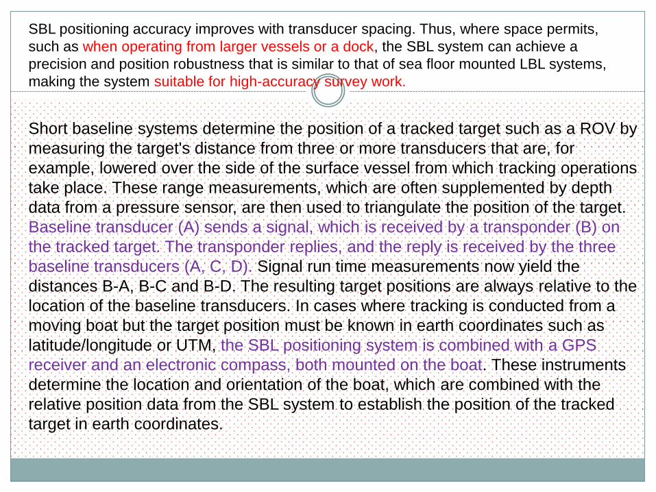
SBL positioning accuracy improves with transducer spacing. Thus, where space permits,
such as when operating from larger vessels or a dock, the SBL system can achieve a
precision and position robustness that is similar to that of sea floor mounted LBL systems,
making the system suitable for high-accuracy survey work.
Short baseline systems determine the position of a tracked target such as a ROV by
measuring the target's distance from three or more transducers that are, for
example, lowered over the side of the surface vessel from which tracking operations
take place. These range measurements, which are often supplemented by depth
data from a pressure sensor, are then used to triangulate the position of the target.
Baseline transducer (A) sends a signal, which is received by a transponder (B) on
the tracked target. The transponder replies, and the reply is received by the three
baseline transducers (A, C, D). Signal run time measurements now yield the
distances B-A, B-C and B-D. The resulting target positions are always relative to the
location of the baseline transducers. In cases where tracking is conducted from a
moving boat but the target position must be known in earth coordinates such as
latitude/longitude or UTM, the SBL positioning system is combined with a GPS
receiver and an electronic compass, both mounted on the boat. These instruments
determine the location and orientation of the boat, which are combined with the
relative position data from the SBL system to establish the position of the tracked
target in earth coordinates.

SBL Manufacturers
MORS (Oceano)
Nautronix (Honeywell) RS5D
Sonardyne SBL
Advantages
• Low system complexity makes SBL an easy
tool to use.
• Good range accuracy with time of flight
system.
• Spatial redundancy built in.
• Ship based system – no need to deploy
transponders on the seafloor.
• Small transducers/gate values.
• Disadvantages
• System needs large baselines for accuracy
in deep water (>40m).
• Very good dry dock/structure calibration
required.
• Detailed offshore calibration of system
required - usually not rigorously completed.
• Absolute position accuracy depends on
additional sensors - ship's gyro and vertical
reference unit.
• >3 transceiver deployment poles/machines
needed.

LBL - Long Base Line
The calculation of position is based on
range measurements only. The ROV, a
subsea module and the vessel are
positioned relative to a calibrated array of
transponders.

LBL Acoustic Positioning System used to track underwater vehicles and divers.
LBL systems use
networks of sea-floor
mounted baseline
transponders as
reference points for
navigation. These are
generally deployed
around the perimeter
of a work site. The
LBL technique results
in very high
positioning accuracy
and position stability
that is independent of
water depth. It is
generally better than
1-meter and can reach
a few centimeters
accuracy.

These range measurements, which are often supplemented by depth data (Z)
from pressure sensors on the devices, are then used to triangulate the
position of the vehicle or diver. A diver mounted interrogator (A) sends a
signal, which is received by the baseline transponders (B, C, D). The
transponders reply, and the replies are received again by the diver station (A).
Signal run time measurements now yield the distances A-B, A-C and A-D,
which are used to compute the diver position by triangulation or position
search algorithms. The resulting positions are relative to the location of the
baseline transducers. These can be readily converted to a geo-referenced
coordinate system such as latitude/longitude or UTM if the geo-positions of
the baseline stations (B, C, D) are first established.
LBL Acoustic Positioning Method
LBL systems are generally applied to
tasks where the required standard of
positioning accuracy or reliability exceeds
the capabilities of USBL and SBL
systems. LBL Transducer

LBL Manufacturers
Benthos Edgetech (EG&G)
Imetrix MORS (Oceano)
Nautronix (Honeywell) 906, 916 Sonatech
Kongsberg Simrad 408 Sonardyne L/USBLPAN, Compatt.
Kongsberg Simrad 418 Combined LBL/USBL
The Multi-User Long
Base Line (MULBL
by Konsberg), is a
hydroacoustic
positioning system.
Several in dividual
vessels and
Remotely Operated
Vehicles (ROVs) can
position themselves
using the same
seabed transponder
array.
Advantages
• Very good position accuracy independent of water depth.
• Observation redundancy.
• Can provide high relative accuracy positioning over large
areas.
• Small transducer – only one deployment machine/pole.
• Disadvantages
• Complex system requiring expert operators.
• Large arrays of expensive equipment.
• Operational time consumed for deployment/recovery.
• Conventional systems require comprehensive calibration
at each deployment.
LBL Acoustic Positioning Method

Remotely Operated Vehicles (ROVs)
This term has been fairly well received around the industry,
however, the debate will likely expand regarding LCAUVs
(LCROVs–Low Cost ROVs (add a “V” and you get Very low
cost)) as the academic community advances the field toward
smaller and cheaper autonomous (self-running) vehicles. And,
in the extreme, are all the systems discussed really vehicles?
Thus, the question of which term to choose: ROV, AUV, UUV,
RCV, RPV, LCROV, VLCROV, LCAUV... And, they are not just
“undersea” vehicles, they are working the inland waters at an
ever increasing pace. ROVs will primarily pertain to tethered (繫纜) systems, including expendable fiber optic tethers; AUVs
(Autonomous Untethered Vehicles) will deal with untethered
systems, to include non-tethered communication links such as
acoustics; UUVs (Unmanned Undersea Vehicles) will remain
with the US Navy and the military; LCROVs will remain
inexpensive vehicles.

VARE Industries, Roselle, New Jersey, developed a maneuverable underwater camera
system–a Mobile Underwater Vehicle System. Serial No. six–was delivered to the Naval
Ordnance Test Station (NOTS) in Pasadena, California, in 1961. Called the VARE vehicle, or
XN-3, it was equipped with a clamshell claw and operated by the Navy laboratory.

The PAP-104s, manufactured by Societie Eca, Meudon, France, were flowing off a high-
speed production line 1975–relatively speaking. The small mine neutralization vehicle, which
could inspect and identify explosive ordnance with its onboard CCTV, had the capability of
delivering an explosive charge to the site, which would then be detonated from the surface.

The pioneer of the ROV industry -- Drew Michel. While working with Taylor
Diving in the Gulf of Mexico, he demonstrated the potential of the small vehicles
and led their introduction into the oil industry.

Perry RECON IV
SCORPIO
Perry Offshore in Florida picked up the US
Navy’s design of the NAVFAC SNOOPY
vehicle and soon had a line of vehicles
called RECON on the market.
AMETEK, Straza Division, in San Diego,
developed the Deep Drone for the US
Navy and soon turned that into their
SCORPIO line of vehicles.
ROVs in early 1980s’ (Adolescence stage)

Immaturity Stage (Late 1980s): The offshore industry is experiencing a
growth spurt in the early eighties and the first conference dedicated to ROVs
is held in San Diego in 1983.
Canadian entrepreneur (Jim
McFarlane) bought into the
business with a series of low cost
vehicles–DART, TREC and
TROV– and International
Submarine Engineering in
Vancouver, British Columbia
became a competitor. Not initially
known for their reliability, they
never the less made a foothold
and provided whatever the user
wanted, becoming a world leader
in the production of reliable
industrial grade ROVs.
With the collapse of oil prices in 1986,
the number of manufacturers of large
ROV systems began to shrink, the
developers of the LCROVs began to
emerge. The technological advances
had finally been made to miniaturize
the vehicles to a point where they were
"easily" portable and available at a cost
that academic institutions and civil
organizations could afford. The first to
break through was the MiniRover,
developed by Chris Nicholson, soon
followed by Deep Ocean Engineering’s
Phantom vehicles. Other variations
began to appear around the world,
however, DOE, and Benthos (which
picked up the MiniRover line), together
cornered the lion’s share of the market.
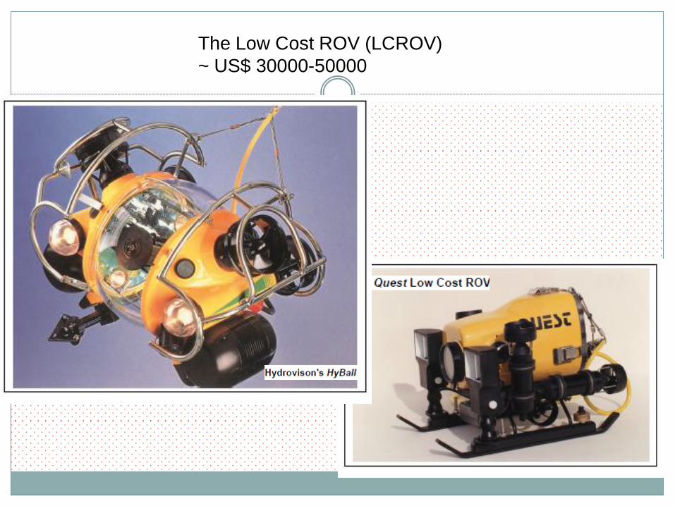
The Low Cost ROV (LCROV)
~ US$ 30000-50000

The controls for the Phantom 300 are very simple and user friendly
making it easy to use by inexperienced researchers. The Phantom 300
has a Sony zoom color camera on a tilt platform and fixed lights. The
cable is 250 feet long allowing access to depths of 200 feet seawater.

Maturity Stage (1990+)
The US Navy reached the magic 20,000-foot (6,096-meter) barrier in 1990–
twice. The first time was with the CURV III vehicle that once again morphed into
a deeper, 20,000-foot (6,096- meter) plus configuration.
Operated by Eastport International for the US Navy’s Supervisor of Salvage,
CURV III reached a depth of 20,105 feet (6,128 meter).
Less than a week later, that record was broken by the Advanced Tethered
Vehicle’s record dive to 20,600 feet (6,279 meters).
Japan stormed onto center stage with a series of excellent vehicles topped
by the Kaiko. The Kaiko not only took over the record for the deepest dive,
but also obliterated it, reaching the deepest point in the Mariana Trench–
35,791 feet (10,909 meters).
Today, a quick estimate indicates there are over
100 vehicle manufacturers, and over 100
operators using approximately 3000 vehicles of
various sizes and capabilities.

Deep Ocean Engineering Phantom S2 ROV
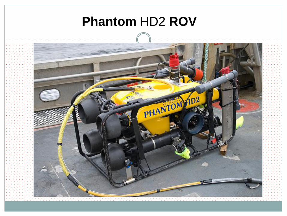
Phantom HD2 ROV

Observation Class ROVs

Work Class ROVs

High Capability Electric ROVs
A new class of ROV is not necessarily low cost and can approach the $500,000
mark. These new vehicles feature the latest in technology from Brushless DC
motors (thrusters) to PC-based control systems and fiber optic telemetry systems.
The ability to do heavy work is still not possible with the electric ROVs, primarily
limited by the needed electro-hydraulic design nature of modern manipulator and
work systems.
Perry Tritech's VOYAGER Deep Sea Systems International's MaxROVER

Medium Sized Vehicles The electro-hydraulic vehicles ranging from 20-100
horsepower typically, which can only carry moderate
payloads and have limited through-frame lift capability.
Perry Tritech's (originally AMETEK's) Scorpio
These ROVs range in
weight from 1,000-
2,200 kg with typical
payload capacities in
the 100-200 kg range.
This class was
developed to perform
work, carrying one or
two manipulators, in
high current conditions,
capable of working in
3-knot or greater
currents.

Large Sized Vehicles The vehicles range in weight from about 2,000-6,500
kg, used for current deep water operations to 2,500
meters ranging from 100-250 horsepower. These
vehicles may stand over 8 ft (2.4 m) tall.
Perry Tritech's TRITON XL

Large Class ROVs There is a significant increase in difficulty when extending the
operating depth from 2,500 m to 3,000 m. The weight of an
armored umbilical becomes critical, having to support its own
weight suspended from the surface.
Tritech's Triton ST
Only a few of
these vehicles
have been
completed.

Ultra-Deep Vehicles This class of vehicle is represented by
those special-built ROVs with depth
capabilities of 4,000 meters and beyond.
Monterey Bay Aquarium Research Institute's (MBARI) Tiburon
It is lower
in power to
keep
umbilical
sizes small
and is used
primarily
for deep
ocean
research,
search and
salvage
missions.

Mitsui's Kaiko
3.1x2.0x2.3m
11000m
5600 KG
Many of the ultra-deep systems are designed for science. A
scientist can observe life in the very deep ocean for extended
periods of time with the use of this type of ROV.

The French Epaulard built by ECA
was the first acoustically controlled
AUV to dive to 6,000 m. The vehicle
weighed nearly 3,048 kg and was 13
ft (4 m) long, 3.6 ft (1.1 m) wide and
6.6 ft (2 m) high. Built in 1981, this
AUV was well ahead of its time. The
vehicle is now retired and on display
at IFREMER.
AUVs Its attend is to get rid of the umbilical and
lett the mature vehicle go its own way.

SIRENE, developed by IFREMER, is designed to land a benthic station with high accuracy
in depths to 4,000 m. The AUV is tele-supervised through a bi-directional acoustic link. It is
an 4 tons free swimming shuttle positioned via a hybrid acoustic long baseline, dead
reckoning system aboard the vehicle itself.

Hugin, in its commercial role
as a survey and inspection
tool, for the tasks such as
deep water seabed mapping
and pipeline inspection, and at
a fraction of the cost of ROV
systems. The main advantage
of the AUV is that it can get a
sonar closer to the seabed
resulting in much higher
resolution data, while
eliminating the umbilical
greatly increases its survey
speed and maneuverability.
The developers consisted of FFI
(Norwegian Defense Research
Establishment), Kongsberg Simrad
and the Norwegian Underwater
Technology Center (NUTEC).

US Defense Advanced Research Projects Agency's (DARPA) AUVs
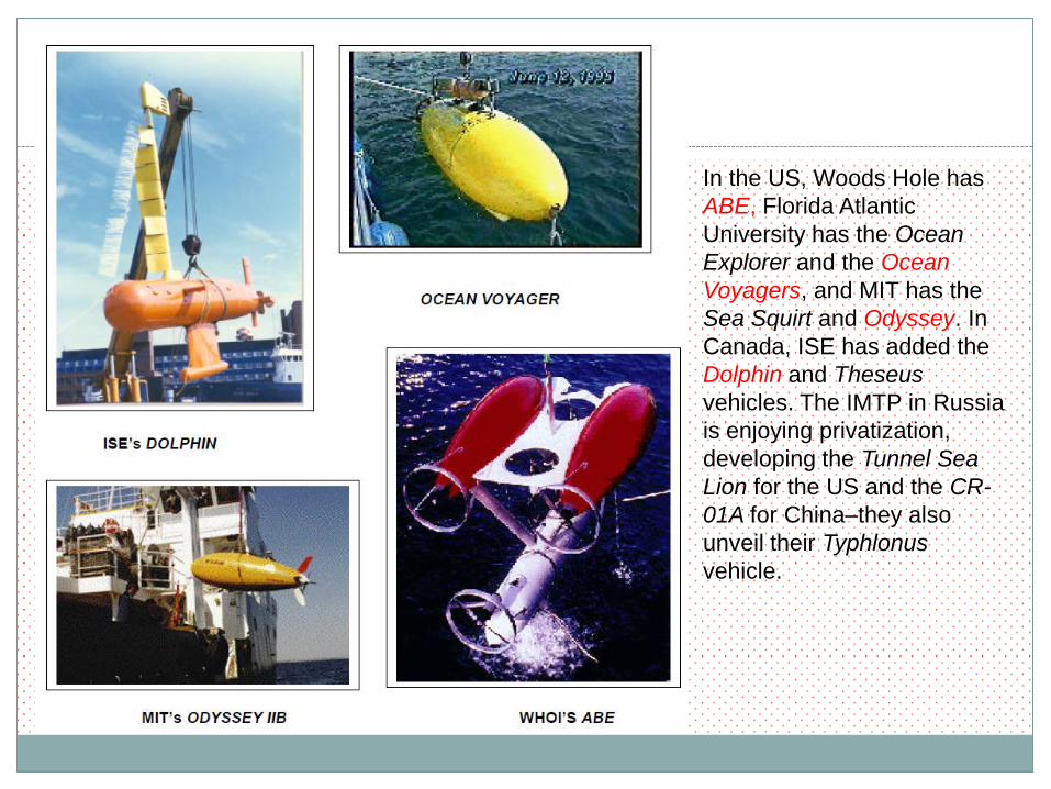
In the US, Woods Hole has
ABE, Florida Atlantic
University has the Ocean
Explorer and the Ocean
Voyagers, and MIT has the
Sea Squirt and Odyssey. In
Canada, ISE has added the
Dolphin and Theseus
vehicles. The IMTP in Russia
is enjoying privatization,
developing the Tunnel Sea
Lion for the US and the CR-
01A for China–they also
unveil their Typhlonus
vehicle.

Towed Systems
W.S. Ocean Systems Ltd.'s U-TOW
Typical sensors used aboard these vehicles are CTDs,
transmissometers, flourometers, nephelometers,
bioluminescence and irradiance meters, optical plankton
recorders, dissolved oxygen, pH, chlorophyll and others.

Cable/Pipeline Location Systems
This class of vehicle is specifically
designed to locate cables or pipeline
either buried or unburied on the
seabed. The vehicles are normally
either a conventional towed body, or
a sled. The sleds are commonly
used in shallow water and are
dragged along the seafloor by the
surface support craft. Both types
carry either a magnetometer or
fluxgate gradiometer for locating
metallic objects. A very unique
design by Seatec, incorporated
spinning rotors on the tow body that
allow the vehicle to be steered along
a pipeline.
Seatec's Towed Vehicle

The system has the capability of flying via its thrusters
in a neutrally buoyant state or becoming heavy and
crawling on the seabed. The system is fitted with a
jetting tool for cable or flexible pipe burial.

Soil Machine Dynamics Ltd. Plough Plows come in all sizes and
configurations, weighing up to 80
tons, resisting tow forces to 250
tons and capable of shallow water
work to depths of 1,500 m.
Not all plows are used to dig trenches; some specialty plows
are built just as back-fill systems for filling in trenches dug by
other plows. End of Class