understanding wireless connectivity in the industrial iot · · 2016-12-14understanding wireless...
TRANSCRIPT

Understanding Wireless Connectivity
in the Industrial IoT
www.ti.com/wirelessconnectivity

Understanding Wireless Connectivity in the Industrial IoT
Contents Page
White Paper
Wireless connectivity design considerations for the industrial IoT ........................................................3
Blog Posts
The Internet of industrial Things ........................................................................................................12
Building the industrial Internet of Things ...........................................................................................13
Taking Power to a New Low with the SimpleLink™ ULP Wireless MCU Platform..............................15
Bluetooth® Smart in Industrial ...........................................................................................................18
The Shocking Impact of Poor RF Selectivity and Blocking ................................................................20
TI Design Reference Designs
Humidity & Temp Sensor Node for Star Networks Enabling 10+ Year ..............................................22 Coin Cell Battery Life Ref Design
Wireless Motor Monitor Reference Design ........................................................................................23
SimpleLink Multi-Standard CC2650 SensorTag Reference Design ....................................................25
ETSI Cat. 1 Receiver-Capable wM-Bus 169-MHz RF Subsystem for ...............................................26 Smart Gas and Water Meters
Implementing SimpleLink Wi-Fi® Connectivity in a Smart Electric Meter ............................................27
Smart Plug with Remote Disconnect and Wi-Fi Connectivity ............................................................28
Bluetooth Low Energy (Bluetooth Smart) to RS-485 Gateway ..........................................................29
CC2540 Bluetooth Low Energy USB Dongle Reference Design .......................................................30
Gas Sensor Platform with Bluetooth Low Energy .............................................................................31
Smart Home and Energy Gateway Reference Design .......................................................................32
Product Overviews
SimpleLink ultra-low power wireless MCU platform .........................................................................35
SimpleLink Wi-Fi Family CC3100/CC3200 wireless MCU platform ...................................................37
WiLink™ 8 Wi-Fi+ Bluetooth/BLE Modules ......................................................................................39
Dual-mode Bluetooth CC2564 smart RF transceiver ........................................................................41
Bluetooth Smart high-temperature CC2540T wireless MCU .............................................................43

Wireless connectivity design considerations for the industrial IoT
Olivier Monniermarketing director, wireless connectivity solutions
Eran Zigmanbusiness line manager, wireless connectivity solutions
Amit Hammerbusiness line manager, wireless connectivity solutions
Texas Instruments
Whi
te P
aper
3

Wireless connectivity design considerations for the industrial IoT 4 July 2015
Introduction
Wireless communications, dominant in consumer electronics for some time now, is quickly making its way into the industrial Internet of Things (IoT). Developers of industrial systems, once freed from the restrictions of cables, are discovering new ways to increase efficiencies and productivity, cut costs and better control processes and equipment. In fact, the only limit on industrial wireless applications appears to be the imagination of developers.
Enabled by ultra-low power sensors and wireless communications devices, as well as highly integrated microcontrollers (MCUs), the IoT is quickly spreading throughout traditional industrial markets like factory and building automation, the energy infrastructure, smart lighting, as well as non-industrial markets such as automotive, retail, health care and others. In many cases, new wireless applications interoperate and enhance the established wired systems, providing value-added capabilities that ride the air waves instead of the wires. For instance, what had been a complex human/machine interface (HMI) can now run as a convenient app on a smartphone or tablet in the wireless industrial IoT. Moreover, tapping into powerful cloud-based analytics in real time adds another dimension to the sophistication of industrial applications.
Of course, system designers should consider a number of factors with regards to wireless connectivity. These include choosing the particular wireless technology that best fits the requirements and use cases of the application, the power consumption and the compatibility of the technology with other devices such as sensors, MCUs, gateways, servers and others, the ease of integrating wireless technology into industrial equipment, cloud connectivity and security.
Going wireless – it needs to be easy
Integrating wireless connectivity into industrial
systems has become vastly easier in recent years
as new end-to-end building blocks – low-power
sensors, wireless connectivity devices, MCUs,
gateways and servers – have been introduced.
Industrial system developers now have access to
a wide variety of wireless technology with diverse
capabilities and varying degrees of integration. For
example, some technology suppliers have simplified
the inclusion of wireless connectivity into industrial
systems by integrating wireless connectivity with the
processing capabilities of an MCU. This significantly
reduces the need for the industrial system developer
to be an expert in radio frequency (RF) design
techniques and gives developers a powerful MCU
for running an application or subsystem. Some of
these wireless MCUs include the entire wireless
protocol stack as well as security measures. Other
more integrated alternatives include as much as
possible in one device, such as cloud connectivity,
local wireless protocols, security protections
and other capabilities in an attempt to make the
inclusion of wireless connectivity a plug-in module
exercise.

Wireless connectivity design considerations for the industrial IoT 5 July 2015
In addition to the devices and capabilities needed,
industrial system designers can now access the
extensive support ecosystems that some wireless
technology suppliers provide. The more complete
ecosystems feature an array of developer kits,
community support, reference designs, already
integrated wireless protocol stacks, app developer
tools, integrated development environments
(IDE) for software programmers and many of the
software and hardware modules that are typically
implemented in industrial settings.
The more comprehensive suppliers of wireless
technology are able to ensure end-to-end inter-
operability among sensors, intermediary devices,
industrial protocols like RS-485, RS-232 and
the various real-time Ethernet networks, and the
cloud. Such suppliers have simplified designing-in
wireless connectivity and at the same time ensure
interoperability with the cloud and a variety of IoT
end nodes.
Industrial wireless: One size won’t fit all
Fortunately, a variety of local area wireless
connectivity standards with a wide range of
capabilities and unique characteristics is available.
This is especially beneficial to the developers of
industrial systems because industrial applications
cover a broad spectrum of use cases and each
one has its own set of challenges. Developers are
able to select the wireless connectivity technology
that best meets the requirements of the application.
For example, the developers of a smart metering
system for a utility grid might decide that the longer
signaling range of a Sub-1 GHz wireless protocol
is best suited to this application. Another design
team working on a home automation system could
Factory automation
Motor drive and remote control
Building automation
Smart grid
Figure 1: Examples of industrial applications where wireless connectivity may be implemented
Gate
way (O
pt.
)
MCURF
TransceiverSensor
Discrete
Gate
way (O
pt.
)
MCUWireless Network
Processor
Sensor
• RF stacks +• RF transceiver
• Application• RF stacks
• Application
MCU + Wireless Network Processor
Sensor
Gate
way (O
pt.
)
• RF stacks +• RF transceiver +• MCU +• Optional cloud agent
Wireless Microcontroller
Wireless MCU
Figure 2: Integration variations for cloud connectivity
Whi
te P
aper

Wireless connectivity design considerations for the industrial IoT 6 July 2015
NFC RFID
Bluetooth® Bluetooth low
energyProprietary
2.4 GHz ZigBee® Wi-Fi® 6LowPANProprietary Sub-1 GHz
Netw
ork
type Identification
Personal connection Customizable Mesh
Existing infrastructure IP Mesh Customizable
Rang
e
Proximity Personal area networks Local area networksNeighborhood area
networks
Key
diffe
renc
es
Data• Up to 848 Kbps• No battery to
coin cell
Data or voice• Up to 3 Mbps• Coin cell to AAA
Data• Up to 1 Mbps• Coin cell
Data• Up to 256 Kbps• Energy
harvesting to AAA
Voice or video• Up to 100 Mbps• AA battery
Data• Up to 256 Kbps• Energy
harvesting to AAA
Data• Up to 1 Mbps• Coin cell
Indu
stria
l app
licat
ions
• Device configuration / Firmware upgrade
• Lighting• Wire
replacement• Beaconing• Asset tracking• Factory
automation
• Building and factory automation
• Beaconing
• Smart energy• Building
automation• Lighting
networks• Industrial
Internet
• Assets tracking• Remote control
of machinery• Sensors• Building
automation
• Smart energy• Building
automation• Lighting
networks• Low-power
Industrial Internet- gateways
• Metering• Smart grid• Alarm and
security• Environmental
monitoring
opt for Wi-Fi® because of its compatibility with
controlling appliances remotely. Lighting networks
might be better suited to ZigBee® for its low power
consumption, mesh topology and extensive support
ecosystem. 6LoWPAN could be the choice of
developers of a factory automation system who see
real benefit in implementing a network of nodes with
Internet Protocol (IP) addresses. For some systems,
the very low power and limited range of near field
communication (NFC) and Bluetooth® Smart or a
proprietary 2.4-GHz protocol might suffice.
The point is that each wireless technology
has its own set of strengths. An industrial IoT
application is best served when the strengths of
a particular wireless technology is matched with
the requirements of the application. For example,
Bluetooth has been deployed in a host of user
devices, including smartphones and tablets. So an
Remote display / Wireless HMI
Before the emergence of the industrial wireless IoT, an
HMI for a new monitoring application would have required
extensive development and integration of the new
subsystem and display hardware. Now, with low-power
wireless technologies like Bluetooth® Smart, battery-
operated sensors can transmit monitoring data to IoT user
devices such as a smartphone or tablet PC. Technicians
are familiar and comfortable with this sort of device so the
learning curve is short.
Figure 3: Selection table of wireless connectivity technologies for industrial

Wireless connectivity design considerations for the industrial IoT 7 July 2015
industrial application supporting Bluetooth Smart
would have immediate compatibility with many user
devices. 6LoWPAN consumes very little power to
the point where it could be supported by small coin
cell batteries, energy harvesting or both. In addition,
since 6LoWPAN nodes are assigned an IP address,
they can be accessed directly from the cloud. If
the wireless signal must travel a long distance and
penetrate through objects like walls, a Sub-1 GHz
protocol could be most appropriate.
Power consumption
The power consumption of an industrial wireless
application must be examined at the macro level
of the entire system and not just its individual
elements.
To start with, an industrial IoT network would
certainly call for low-power sensors to monitor
factory processes, building equipment, residential
systems, the electrical power grid or whatever the
setting. Today’s most advanced wireless sensors
have brought new meaning to low power. When
teamed with a low-power MCU with wireless
connectivity, some sensor-based IoT end nodes
can operate for up to 10 years on a coin cell battery
while others will operate on energy harvested from
the light, vibration, thermal or RF energy in their
surroundings. Sophisticated power management
as well as precision analog capabilities like analog-
to-digital (ADC) converters and comparators are
also critical to low-power IoT networks. Power
management routines that are able to automatically
place portions of the system into a power-saving
sleep mode can extend the operational life of a
battery considerably and reduce the need for
regular maintenance to change batteries. This could
be critical in applications where an IoT node is
installed in a particularly inaccessible location, like
a machine on the roof of a building, atop a tower
or in a satellite. In these sorts of applications, the
power management subsystem could lengthen the
life of the batteries by keeping most of the system
in a low-power sleep mode except for the sensor
that is monitoring the inaccessible machine. When
the condition being monitored by the sensor, such
as vibration or temperature, exceeds a certain
threshold, the rest of the system could be powered
up so that it could communicate an alarm or take an
action on its own.
Sensors
Sensors deployed in a wireless industrial IoT will
monitor a complex and widely diverse environment
Preventive maintenance was never so easy
Preventive maintenance – heading off a problem
before it happens – is highly valued in many
industrial environments. Wireless connectivity
makes possible a new generation of preventive
maintenance applications. In a power generation
plant, for example, wireless sensors could
communicate with a technician’s smartphone when
vibration in a machine exceeds a certain limit. Then,
preventive maintenance could return the machine
to its proper working order before a catastrophic
problem occurs.
Whi
te P
aper

Wireless connectivity design considerations for the industrial IoT 8 July 2015
where slight changes in conditions can be critical.
High-resolution measurements and the monitoring
of chemical composition, access control, vibrations,
asset tracking information, motion, pressure,
temperature, UV radiation, gas and fluid flow and
many other variables could be required.
Some easy-to-implement devices integrate
several of these capabilities, combining low-
power wireless connectivity over Bluetooth
Smart, ZigBee, 6LoWPAN, Sub-1 GHz, Wi-Fi or
a proprietary protocol, with an MCU that’s able to
control a sensor and run an application. This also
includes several interfaces to I/O peripherals. By
bundling many of the basic capabilities into an
integrated platform, such devices reduce the power
consumption of the node even further than that of a
discrete implementation.
Security
Security is an issue of concern in practically every
aspect of the economy, including industrial wireless
IoT networks. Security can be implemented in a
number of ways, but the goal is always to prevent,
detect and respond to malicious behavior when it
occurs. On a physical level, IoT nodes should be
as tamper resistant as possible. But with electronic
systems, security must also be provided to protect
IP investments as well as a loss of control over the
system to rogue processes. In low-power, often
remote wireless nodes, this security protection is
usually best provided through hardware-based
accelerators or co-processors executing security
algorithms because this will consume less power
and not diminish the throughput of the node.
Conformance and certification to wireless standards,
like Wi-Fi, Bluetooth Smart and others, also affect
security since standards either incorporate built-in
security measures or are compatible with security
standards. Wi-Fi, for example, has a number of
security standards associated with it, such as
Wi-Fi Protected Access (WPA), SSL, TLS, X.509
and others. Cryptographic and authentication
Figure 4: SimpleLink™ SensorTag quickly connects sensors to the cloud
Building security
Wireless connectivity can ensure the security of
buildings in a convenient way. For example, locks,
motion sensors, cameras, exterior and interior
lighting, keypads and other security devices could
connect through ZigBee or Sub-1 GHz to a Wi-Fi-
based gateway with access to the Internet. With
this sort of system, a business owner/operator who
may not currently be at the property, could grant
temporary access to a trusted employee through
their smartphone and a cloud-based security
application.

Wireless connectivity design considerations for the industrial IoT 9 July 2015
algorithms can also protect stored data. In addition,
hardware security measures can be taken, such
as secure boot loading mechanisms and logical
memory locks.
Connectivity to the cloud and wired networks
At some point, most industrial wireless IoT networks
usually interface with the cloud and/or traditional
industrial wired networks.
Cloud connectivity has many advantages, but the
first issue to address is where in the local IoT will this
connectivity be implemented. Most likely, the IoT will
connect to the cloud through one of its upper levels,
such as a server or gateway. The gateway or server
would aggregate cloud communications from other
nodes and transmit over the cloud. Some industrial
IoT implementations will access the cloud in order
to connect with cloud-based strategic partners,
like IBM, PTC or other third-party firms that offer
application-specific analytics, specialized processing
and other services that are sometimes required.
Probably the most critical issue relative to cloud
connectivity will be how easy or difficult it will be
to accomplish. Historically, developers of industrial
systems have not needed experience in radio
frequency (RF) engineering. In many cases, wireless
cloud connectivity will be provided by Wi-Fi in a
gateway or server, since Wi-Fi is already ubiquitous
in many industrial settings and it features the
requisite bandwidth and capacity for effective cloud
connectivity. Some IoT end nodes might require
dual wireless connectivity; Bluetooth Smart, ZigBee
or 6LoWPAN for local interaction with sensors and
operators, and Wi-Fi connectivity for linking into the
wider industrial IoT and the cloud. Some industrial
Wi-Fi solutions have been bundled with out-of-the-
box connectivity capabilities, including single or dual
wireless technologies, certified wireless protocols
and security algorithms, sample code libraries and
development tools and kits.
In addition to cloud connectivity, wireless industrial
applications will likely interact with traditional
wired equipment networks. For example, factory
automation or building automation systems could
very well feature both wired and local area wireless
networks in the same environment. In such cases,
the ability to interface wireless connectivity devices
with wired connectivity protocols like RS-485,
RS-232 and others will be quite beneficial. A
technician might then monitor processes on the
factory floor through a wireless connection to
an HMI which is monitoring a wired equipment
network running one of the industrial real-time
Ethernet protocols like EtherCAT®, EtherNet/IP™,
PROFINET® or POWERLINK.
Conclusions
Texas Instruments has long had the industry’s
most extensive portfolio of enabling wireless
technologies for industrial IoT networks. A pioneer
in low-power innovation, TI’s technologies include
both integrated and discrete solutions, such as
ultra-low power MCUs and sensors, analog devices
like ADCs and comparators, as well as WiLink™
Wi-Fi and Bluetooth combo connectivity devices
and SimpleLink™ wireless MCUs which have been
integrated with local area wireless connectivity for all
of the popular standards in addition to being easily
customizable to proprietary protocols. Moreover, the
SimpleLink wireless MCUs include the most popular
peripheral interfaces as well as on-chip memory and
Whi
te P
aper

a sensor controller engine that quickly and easily
interfaces to a wide range of TI’s sensors.
All solutions are capable of operating over the
40–85°C industrial temperature range. Highly
programmable, TI’s wireless solutions are supported
by an extensive ecosystem of tools, libraries of
ready-to-use software modules, reference designs
and other resources that allow industrial system
developers to not only customize and differentiate
their products, but also deliver their new system to
the market quickly and efficiently.
For more information go to
www.ti.com/wirelessconnectivity
ZigBeeCOEX I/F
®
BT: UART
WRF2
BG1
BG2
BT
PM
F
Note: Dashed lines indicate optional configurations and are not applied by default.
D
D
RF_ANT2
RF_ANT1
VIO
VBAT
26M TCXO
Aband5-GHzDPDT
2.4-GHzSPDT
WRFAMA
C/P
HY
MA
C/P
HY
WRF1
BTRF
WLAN : SDIO
BT EN
WLAN EN
32 KHz
Figure 5: WiLink 8 dual-band industrial module (WL1837MOD variant shown)
© 2015 Texas Instruments Incorporated
Important Notice: The products and services of Texas Instruments Incorporated and its subsidiaries described herein are sold subject to TI’s standard terms and conditions of sale. Customers are advised to obtain the most current and complete information about TI products and services before placing orders. TI assumes no liability for applications assistance, customer’s applications or product designs, software performance, or infringement of patents. The publication of information regarding any other company’s products or services does not constitute TI’s approval, warranty or endorsement thereof.
SimpleLink and WiLink are trademarks of Texas Instruments. All trademarks are the property of their respective owners.
10Return to ToC

11
Wireless connectivity blog posts
Blo
g P
ost
s

The Internet of Things or IoT is not just for consumer ap-plications. It has a strong potential in the industrial sector because of the services that will be provided as more sensors and equipment are connected to the cloud. It is important that IoT not be confused with machine-to-machine or M2M connectivity since they are not the same. M2M is traditionally based on proprietary technology that is a closed environment vs. IoT which offers an open environment and leverages stan-dard Internet accessibility and services – just like the ones we humans use. This level of openness enables a gas sensor to tweet or text an operator when there is a problem, which is not straightforward with an M2M system.
With cloud connectivity there is a lot of potential for IoT- enabled applications within the industrial market.
• Smart manufacturing: Manufacturers are adding wireless connectivity to their products or production line to improve the manufacturing process. With integrated wireless connectiv-ity, manufacturers are better able to get information from the factory floor to their cloud systems to quickly uncover and address any issues long before the product leaves the factory. Manufacturers also want to use connectivity to gather informa-tion about equipment in the field. This information helps them find bugs, monitor equipment and also allows for software and firmware updates over-the-air – something that was not pos-sible before.
• Building automation: Much like factory automation, building automation can connect to sensors to turn lights on and off depending on occupancy and allow dynamic control of HVAC systems, which allows for energy optimization. Predicative maintenance is also a benefit to ensure that service is done in a timely fashion, which reduces costs.
• Smart cities: Connecting elements within a smart city to the IoT can provide enhancements to improve electricity and water usage with e-meters to improve conservation efforts. Connected smart street lights as well as cloud-connected sur-veillance and traffic-control monitors help provide a smooth-running city. Last, sensors throughout the city detect gas and water-pipe leak keep citizens safe and ensure operation.
• Other markets: There are additional opportunities to improve employee health and safety through the IoT outside of the
workplace. Connected wearables and healthcare monitoring improves overall health and wellness. And IoT within automo-biles provides infotainment but also lighter and more fuel effi-cient cars with wire replacement and predictive maintenance to save on costly repairs.
Many of the examples above play out in the consumer market as well. However, the industrial IoT is different than consumer applications. Industrial requires different interfaces and protocols that are robust against noise, environmental changes, controlled latency and are highly secure because of the conditions and applications they are used in.
Additionally, the industrial market moves much slower than the consumer market so its move to connected IoT en-hancements will take some time. The benefits of predicative maintenance, monitoring and data analysis to improve output or working conditions, combined with the availability of the right hardware and software solutions, will provide a financial reason to migrate to IoT-connected systems in the future – its just a question of when.
• Learn more about TI’s role in the IoT and its broad portfolio of IoT-ready solutions
• Watch this video and see how TI is innovating for industrial automation
• Read more blogs on TI’s IoT solutions
The Internet of industrial Things
Blo
g P
ost
s
12
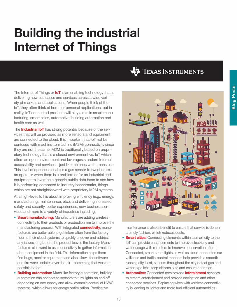
The Internet of Things or IoT is an enabling technology that is delivering new use cases and services across a wide vari-ety of markets and applications. When people think of the IoT, they often think of home or personal applications, but in reality, IoT-connected products will play a role in smart manu-facturing, smart cities, automotive, building automation and health care as well.
The Industrial IoT has strong potential because of the ser-vices that will be provided as more sensors and equipment are connected to the cloud. It is important that IoT not be confused with machine-to-machine (M2M) connectivity since they are not the same. M2M is traditionally based on propri-etary technology that is a closed environment vs. IoT which offers an open environment and leverages standard Internet accessibility and services – just like the ones we humans use. This level of openness enables a gas sensor to tweet or text an operator when there is a problem or for an industrial end-equipment to leverage a generic public data base to see how it is performing compared to industry benchmarks, things which are not straightforward with proprietary M2M systems.
At a high-level, IoT is about improving efficiency (e.g., energy, manufacturing, maintenance, etc.), and delivering increased safety and security, better experiences, new business ser-vices and more to a variety of industries including:
• Smart manufacturing: Manufacturers are adding wireless connectivity to their products or production line to improve the manufacturing process. With integrated connectivity, manu-facturers are better able to get information from the factory floor to their cloud systems to quickly uncover and address any issues long before the product leaves the factory. Manu-facturers also want to use connectivity to gather information about equipment in the field. This information helps them find bugs, monitor equipment and also allows for software and firmware updates over-the-air – something that was not-possible before.
• Building automation: Much like factory automation, building automation can connect to sensors to turn lights on and off depending on occupancy and allow dynamic control of HVAC systems, which allows for energy optimization. Predicative
maintenance is also a benefit to ensure that service is done in a timely fashion, which reduces costs.
• Smart cities: Connecting elements within a smart city to the IoT can provide enhancements to improve electricity and water usage with e-meters to improve conservation efforts. Connected, smart street lights as well as cloud-connected sur-veillance and traffic-control monitors help provide a smooth-running city. Last, sensors throughout the city detect gas and water-pipe leak keep citizens safe and ensure operation.
• Automotive: Connected cars provide infotainment services to stream entertainment and provide navigation and other connected services. Replacing wires with wireless connectiv-ity is leading to lighter and more fuel-efficient automobiles
Building the industrial Internet of Things
Blo
g P
ost
s
13

with sensor-driven predictive maintenance to save on costly repairs.
• Retail stores: A connected retail environment can better track inventory and dynamically change digital shelf labels. Com-bined with customer loyalty programs, IoT-connected beacons within a store can serve up coupons and offer sales based on customer preferences directly to their smartphones while they are shopping.
• Healthcare: There are additional opportunities to improve employee health and safety through the IoT outside of the workplace. Connected wearables and health care monitoring improve overall health and wellness.
Many of the examples above play out in the consumer market as well. However, the industrial IoT is different than consumer applications. Industrial requires different interfaces and communication protocols that are robust against noise, environmental changes, controlled latency and are highly secure because of the conditions and applications they are used in.
Additionally, the industrial market moves much slower than the consumer market so its move to connected IoT will take some time. The benefits of predicative maintenance, moni-toring and big data analysis to improve output or working conditions, combined with the availability of the right hard-ware and software solutions, will provide a financial reason to migrate to IoT-connected systems in the future – it’s just a question of how quickly it happens.
• Learn more about TI’s role in the IoT and its broad portfolio of IoT-ready solutions
• Watch this video and see how TI is innovating for industrial automation
• Read more blogs on TI’s IoT solutions
14
The new SimpleLink™ CC26xx/CC13xx ultra-low power plat-form for Bluetooth® Smart, 6LoWPAN, ZigBee®, Sub-1 GHz and ZigBee RF4CE™ is built and designed with low power in mind. We’ve looked at all aspects important to making sure the energy footprint of our solution is as small as possible enabling longer battery lifetimes, smaller batteries or even energy harvesting for battery-less applications.
Application
Contrary to popular belief, that radio transceiver itself is rarely the main contributor to the overall power consumption of a wireless microcontroller (MCU). As various technologies prog-ress, there is more and more need for computing power, even as relatively small sensors and the wireless protocol stacks come with more overhead as the standards evolve.
In the SimpleLink CC26xx family, there are two very energy efficient MCUs available for the application.
ARM® Cortex®-M3
The ARM Cortex-M3 is the main system CPU inside the CC26xx device. One way of measuring the performance of MCUs is by using benchmark tools. One of the more popular benchmarks is CoreMark from the Embedded Microproces-sor Benchmark Consortium (EEMBC). CoreMark is a simple, yet sophisticated, benchmark that is designed to test the efficiency of a processor core used in embedded devices. It is not system dependent, therefore it functions the same regardless of the platform (e.g., big/little endian, high-end or low-end processors, etc.). This benchmark also demon-strates the energy efficiency of the MCU core.
The scores in Table 1 allow for very low average power con-sumption during active use. Running the ARM Cortex-M3 at maximum speed (48 MHz), the CPU operation consumes less than 3 mA and outperforms any wireless MCU running at less efficient cores or at lower CPU clocks. The CC26xx Core-Mark power efficiency (CoreMark / mA) is the best compared to any competitor with a comparable MCU, making it the most energy efficient microcontroller available today.
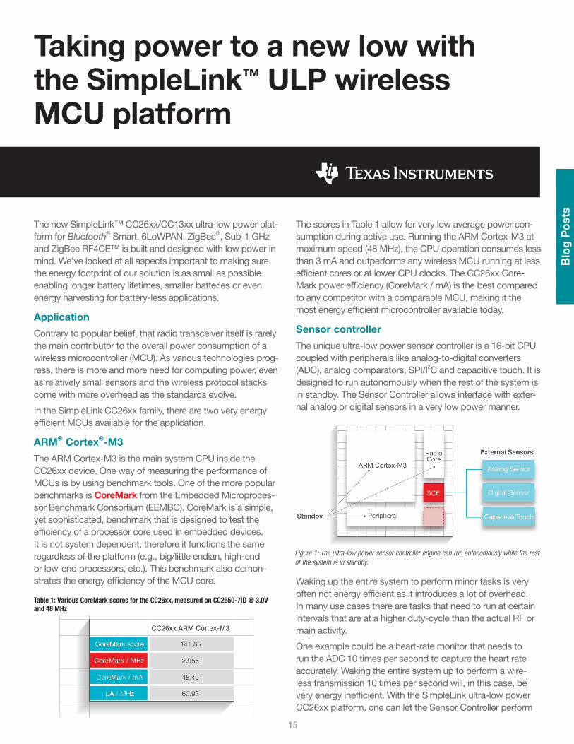
Sensor controller
The unique ultra-low power sensor controller is a 16-bit CPU coupled with peripherals like analog-to-digital converters (ADC), analog comparators, SPI/I2C and capacitive touch. It is designed to run autonomously when the rest of the system is in standby. The Sensor Controller allows interface with exter-nal analog or digital sensors in a very low power manner.
Waking up the entire system to perform minor tasks is very often not energy efficient as it introduces a lot of overhead. In many use cases there are tasks that need to run at certain intervals that are at a higher duty-cycle than the actual RF or main activity.
One example could be a heart-rate monitor that needs to run the ADC 10 times per second to capture the heart rate accurately. Waking the entire system up to perform a wire-less transmission 10 times per second will, in this case, be very energy inefficient. With the SimpleLink ultra-low power CC26xx platform, one can let the Sensor Controller perform
Taking power to a new low with the SimpleLink™ ULP wireless MCU platform
Table 1: Various CoreMark scores for the CC26xx, measured on CC2650-7ID @ 3.0V and 48 MHz
Figure 1: The ultra-low power sensor controller engine can run autonomously while the rest of the system is in standby.
Blo
g P
ost
s
15

all the ADC measurements and wake up the ARM Cortex-M3 every 10th ADC sample for optional further processing and group RF transmission of this data.
In this example, the sensor controller can do 10 ADC reads per second at less than 3 µA average consumption. Perform-ing the same task using the ARM Cortex-M3 will require 10× the power consumption.
The sensor controller can run directly off a pre-scaled 24-MHz clock, making it capable of collecting data and per-forming simple processing of the data.
Radio
Traditionally the peak drain caused by high transmit and receive currents of wireless solutions puts constraints on the batteries that could be used or significantly reduced the battery lifetime. With the very low peak currents of the CC26xx at around 6 mA (0 dBm output), this no longer poses any limitations on the traditional CR2032 batteries and can even allow for smaller batteries to be used. From an average power consumption perspective, the radio is no longer the main contributor and is of less concern and there is no longer a need to back down on the output power to reduce the peak consumption.
Sleep and shutdown
In any battery-operated application, the RF (receive/transmit) duty cycle and its parameters decide the battery lifetime. Between transmissions, it is important to keep the standby currents as low as possible so that there is enough juice in
the battery for the active use. The CC26xx uses an ultra-low leakage SRAM that can be fully retained (20 KB) and in addition have the real-time clock (RTC) running, and registers and CPU state retained while in standby consuming as little as 1 µA. In shutdown, the CC26xx can wake up on external I/O events while drawing as little as 150 nA.
The shelf lives for CR2032s are increasing and some vendors now state up to 10 years of battery life. The average system current drawn from a 220 mAh CR2032 has to be below 2.5 µA to reach 10 years lifetime[2]. If the base current of a system is above this, one cannot reach the maximum potential of the
battery, no matter how low active duty cycle one implements.
How average current affects battery lifetime
Battery life time is mostly about the average power consump-tion. This will be very use-case dependent, but there is a benchmark now available from EEMBC called ULPBench™ that standardizes on datasheet parameters and provides a methodology to reliably and equitably measure MCU en-ergy efficiency. ULPBench uses a common set of workloads that are portable across 8-, 16- and 32-bit microcontrollers, enables the use of MCU low-power modes while focusing on real-world applications utilizing integrated hardware functions. In the end it analyzes the effects of active and low-power conditions[3].
Another common way of looking at average current is to look at a specific use-case for a given technology. For Bluetooth
Figure 2: The sensor controller can significantly reduce average power consumption.
Table 2: Energy efficiency of the sensor controller while running at the main clock.
Figure 3: CC26xx ULPBench scores vs. competition.
16

Smart, one way is to point out the average while keeping a connection between two devices at a given interval.
All of what has been discussed comes into play when look-ing at the power profile of a wireless event. Figure 4 shows a connection event for Bluetooth Smart with wake-up, pre- processing of the software stack, radio events (both receive and transmit) and a post-processing / going back to sleep period.
Further details on how to calculate average currents and bat-tery lifetime for a Bluetooth Smart application can be found in [4].
Reference[1] Cortex-M0+ Processor[2] Marketing Malarkey and Some Truths About Ultra-Low
Power Design, Jack Ganssle 2014[3] EEMBC ULPBench[4] Measuring Bluetooth® Smart Power Consumption
Table 3: Average scores for the CC26xx, measured on CC2650-7ID @ 3.0 V
Figure 4: Power profile of a Bluetooth Smart connection event
Blo
g P
ost
s
17

Have you ever heard of Bluetooth® Smart? It’s the latest addition to the Bluetooth specification and it uses Bluetooth low-energy technology to enable the Internet of Things (IoT) for products that operate on small coin cells for years. How is that possible you may ask? Bluetooth low energy was designed to be low power, only waking up from time to time to transmit small amounts of data with rather high latency in a range that covers up to a couple of meters. Perfect for sen-sors! That’s how it began in 2010.
It took a year or two until the first products showed up on the market in the form of heart-rate belts and smart watches. Then a smartphone came into the picture, Apple® iPhone® 4S. It was the first phone on the market to support Bluetooth low energy and the market took off. The fact that everyone carrying a smartphone, could connect to all kinds of products in a low-power manner was something new. Suddenly, every-one wanted their product to be connected to a smartphone.
As a natural progression came the talk about Internet of Things and cloud connectivity so your smartphone can con-nect to any-thing and so allowing any-thing to connect to the Internet (read cloud). With this dramatic change, firmware updates could be pushed to products out in the field, smart-phones could control helicopter toys and wireless add-ons can replace wires in weird places.
We are at this point closing in on 2015 and all of a sudden, manufacturers are now using Bluetooth Smart (which is be-coming the more common name for Bluetooth low energy) for longer-range communication, high-throughput transfers and tough ISM applications as well. This is not at all what Bluetooth low energy was designed for. However, Bluetooth low energy is now advancing into high-quality industrial ap-plications; replacing whatever has been used for ages, or at least a very long time.
It’s time for a revolution, time for Bluetooth Smart to show its worth in new places. Bluetooth Smart is emerging into unexplored new market segments from hardcore industrial applications and fancy home appliances to trendy beacon-systems [sic].
There are already deployed solutions for use cases including both wired and wireless technologies that can be replaced by Bluetooth Smart. As Bluetooth Smart is evolving and adapt-ing to these new use cases, one might be afraid that there might be a “war” between standards coming. I like to think about it more of an evolution, where the survival of the fittest applies. The future will behold which technology is suitable for what.
However, we can already elaborate on some applications that might be impacted. Take lighting as an example, where ZigBee is dominating the market with smart bulbs connected in a network to a Wi-Fi® gateway. Bluetooth Smart can do star topologies as of now, with a central or smartphone controlling multiple light bulbs. However, ZigBee operates in a mesh network topology which means that information can be routed through nodes and range can be extended beyond the gateway limitation. Bluetooth Mesh is something that could address this in the future as well, if it’s designed in an energy-efficient way (i.e., not using flooding, etc.) and the security
Bluetooth® Smart in industrial
Blo
g P
ost
s
18

is robust including the complete solution for that matter. But what about the already-deployed ZigBee solutions, will those be redundant? Well, not necessarily. What if one node in the ZigBee network adds Bluetooth Smart? Or the gateway includes a Bluetooth Smart interface?
There are other use cases; i.e., Machine to Machine (M2M), cable replacements, asset tracking and automation control that can benefit from Bluetooth Smart in the industrial setting. There are already multiple connectivity technologies with a foothold in the industrial space including Ethernet, ZigBee, Wi-Fi, Sub-1 GHz, etc. and Bluetooth Smart can easily complement these technologies. What is needed is a focus on streamlining a set of technologies to define a wireless super-set similar to the useful Swiss army knife.
Why is Bluetooth Smart a good fit for industrial applications? Read the six-part blog series on ECN Magazine that covers the industrial applications mentioned above and allow me to enlighten you.
Reference[1] Why Bluetooth Smart is perfect for M2M[2] Connecting machinery to the IoT[3] How to use Bluetooth Smart in industrial lighting[4] How you can replace wires with Bluetooth Smart[5] Why Beacon is the next big thing in wireless[6] The key to using Bluetooth Smart in asset tracking
19

At TI we have more than 15 years of experience with low-power RF solutions. Over time, working hands-on with customers, we have learned what it takes to design RF ICs that work well in industrial environments. The wireless com-munication needs to be robust and just plain work. To learn more about our 169-MHz, 315-MHz, 433-MHz, 470-MHz, 868-MHz, 915-MHz and 920-MHz solutions, check out our Sub-1 GHz page.
Recently we wanted to test our newest long-range RF solu-tion against a well-known competitor in the market. Both solutions have really great RF transmission range when tested in a quiet open space, such as in the countryside environment found in this video from our 25-km range test video in South Africa. However, many industrial RF solutions are not deployed in the countryside but rather in urban areas, which is why we shot our latest range test video in downtown Oslo, Norway.
In the video we set up 2 RF links (one with TI’s CC1120 long-range, narrowband, high-performance RF transceiver and one with a long-range wideband competitor) to compare
what happens to the RF link when we introduce an interferer, i.e., an e-meter, into the equation. We were really surprised by the results. The wideband solution basically ceased to function if the interferer was within ~200 meter range. This basically means that an e-meter in a neighboring building can block your wide-band RF link completely.
So why is the wideband solution prevented from receiving data while the narrowband solution is just fine?
There are two main benefits with a narrowband solution. First, there are more RF channels available which enable more systems to coexist peacefully. Secondly, wideband solutions have wider RF receive filters which pick up more RF noise and interference than a narrowband solution. Hence, nar-rowband is the best choice for robust RF solutions in urban and industrial areas. For an in-depth discussion on this topic, please check out our Long-range RF communication: Why narrowband is the de facto standard whitepaper.
The shocking impact of poor RF selectivity and blocking
Blo
g P
ost
s
20Return to ToC

21
Wireless connectivity TI Design reference designs
TI D
esig
ns

DescriptionThis TI Design uses Texas Instruments nano-power system timer, SimpleLink™ ultra-low power wireless microcontroller (MCU) platform, and humidity-sensing technologies to dem-onstrate an ultra-low power method to duty-cycle sensor end nodes. These technologies lead to an extremely long battery life: over 10 years with a standard CR2032 lithium ion coin cell battery. The TI Design includes techniques for system design, detailed test results and information to get the design up and running quickly.
Features• Use of nano-power system timer to duty-cycle the system
results in 10+ year battery life from CR2032 coin cell• Configurable system wakeup interval• Extremely low off-state current (183 nA for 59.97 seconds)• Ultra-low on-state current due to low active processor and
radio transmit currents (4.04 mA for 30 ms)• ±3% Relative humidity accuracy• ±0.2°C Temperature accuracy
Humidity & Temp Sensor Node for Star Networks Enabling 10+ Year Coin Cell Battery Life Ref Design
Part number Name Product family Design kits and Evaluation modules
CC2650 SimpleLink™ multi-standard 2.4-GHz ultra-low power wireless MCU Wireless MCUs View Design Kits & Evaluation Modules
CC2640 SimpleLink ultra-low power wireless MCU for Bluetooth Smart Wireless connectivity View Design Kits & Evaluation Modules
CC2630 SimpleLink ultra-low power wireless MCU for 2.4-GHz IEEE 802.15.4-based RF protocols Wireless connectivity View Design Kits & Evaluation Modules
HDC1000 Low power, high accuracy digital humidity sensor with integrated temperature sensor Sensor products View Design Kits & Evaluation Modules
TPD1E10B06 Single-channel ESD in 0402 package with 10pF capacitance and 6V breakdown ESD protection diodes View Design Kits & Evaluation Modules
TPL5110 Ultra-low-power timer with MOS driver and MOSFET power ON Clock and timing View Design Kits & Evaluation Modules
To download the full TI Design Reference Design visit: http://www.ti.com/tool/TIDA-00374
© 2015 Texas Instruments IncorporatedPrinted in U.S.A.
TI D
esig
ns
22

DescriptionThis TI Design is inspired by the need to monitor the health of motors and machines to accurately predict and schedule maintenance (or replacement) while minimizing cost and down time during industrial production. Millions of industrial motors are monitored today with handheld or wired Piezo ac-celerometer sensing devices. The annual cost of monitoring these motors is approximately $300 per motor.
Recent advancements in ultra-low-power processing tech-nologies, radios and piezo sensor miniaturization have enabled the development and deployment of low-cost, small motor monitors with wireless capabilities. These wireless motor monitors are powered by coin cells that have a battery life of more than 10 years. These systems provide the same broadband sensitivity as existing handheld systems, collect vibrational data and perform spectral analyses on that data. This integrated intelligence lets you deploy and monitor these systems in difficult-to-reach locations. The money these ca-pabilities save can pay for the systems within a few months. The wireless motor-monitoring TI Design uses two different, yet electrically equivalent, form factors for development and testing.
These form factors include:
• The modular form factor• The compact form factor
In the modular form factor, TI LaunchPad™ Development Kits and EM connectors allow you to incorporate multiple radios and processors with energy-management and sensor sub-systems. The compact form factor uses the MSP430FR5969 ultra-low-power microcontroller unit (MCU) with a CC2650 BLE radio, but can be connected to multiple sensor boards.
The standard sensor board supports a PCB Piezotronic vibra-tion sensor.
The 30-pin expansion connector on the small form factor board enables the base-board to be operated with the MCU, the CC2650 radio, or both. The system software assumes you are using both devices. This TI Design focuses on the compact form factor system.
Features• 100-µA MSP MCU analyze/write• 6-mA Bluetooth® Low Energy radio• 40-nA system sleep• 10-KHz/16-bit vibration sensor• iPad®/Android™ visualization• This circuit design is tested and includes firmware, GUI, demo,
and Getting Started Guide
(continued)
Wireless Motor Monitor Reference Design
TI D
esig
ns
23

Part number Name Product family Design kits and Evaluation modules
ADS8320 16-bit, high-speed, 2.7-V to 5-V micro power sampling analog-to-digital converter Analog-to-digital converter View Design Kits & Evaluation Modules
BQ25570 Ultra-low-power harvester power management IC with boost charger and nanopower buck converter Battery management products View Design Kits & Evaluation Modules
CC2650 SimpleLink™ multi-standard 2.4-GHz ultra-low power wireless MCU Wireless MCUs View Design Kits & Evaluation Modules
LMP7716 Dual-precision, 17-MHz, low-noise, CMOS input amplifier Operational amplifier (Op Amp) View Design Kits & Evaluation Modules
MSP430FR5969 16-MHz ultra-low-power microcontroller featuring 64 KB FRAM, 2 KB SRAM, 40 I/O Ultra-low power MCU View Design Kits & Evaluation Modules
TPL5100 Nano power programmable timer with power gating functionality Clock and timing View Design Kits & Evaluation Modules
TPS22969 1-Ohm SPDT analog switch 5-V/3.3-V single-channel 2:1 multiplexer/demultiplexer Signal switches View Design Kits & Evaluation Modules
TPS7A7002 Very-low input, very-low dropout 3-A regulator with enable Linear regulator (LDO) View Design Kits & Evaluation Modules
To download the full TI Design Reference Design visit: http://www.ti.com/tool/tidm-wlmotormonitor
TI devicesOrder samples, get tools and find more information on the TI products in this reference design.
© 2015 Texas Instruments IncorporatedPrinted in U.S.A.
24

DescriptionThe new SimpleLink Multi-Standard SensorTag IoT kit invites you to realize your cloud-connected product idea. Includ-ing 10 low-power MEMS sensors in a tiny package, the kit is expandable with DevPacks to make it easy to add your own sensors or actuators.
Connect to the cloud with Bluetooth® Smart and get your sensor data online in three minutes. The SensorTag is ready to use out of the box with an iOS™ and Android™ app, with no programming experience required to get started.
The new SensorTag is based on the CC2650 wireless MCU, offering 75% lower power consumption than previous Bluetooth Smart products. This allows the SensorTag to be battery powered and offer years of battery lifetime from a single coin-cell battery.
The Bluetooth Smart SensorTag includes iBeacon technol-ogy. This allows your phone to launch applications and customize content based on SensorTag data and physical location.
Additionally, the SensorTag can be enabled with ZigBee® and 6LoWPAN technology.
Visit www.ti.com/sensortag for more information.
Features• Support for 10 low-power sensors, including ambient light,
digital microphone, magnetic sensor, humidity, pressure, accelerometer, gyroscope, magnetometer, object temperature and ambient temperature
• Ultra-low power, with years of battery life from a single coin-cell battery and enabling battery-less applications through the high-performance ARM® Cortex®-M3 CC2650 wireless MCU.
• Cloud connectivity lets you access and control your SensorTag from anywhere
• Multi-standard support enables ZigBee or 6LoWPAN through a simple firmware upgrade
• DevPacks allow you to expand the SensorTag to fit your designs
SimpleLink™ Multi-Standard CC2650 SensorTag Reference Design
Part number Name Product family Design kits and Evaluation modules
CC2620 SimpleLink ultra-low power wireless MCU for RF4CE Wireless connectivity View Design Kits & Evaluation Modules
CC2630 SimpleLink ultra-low power wireless MCU for 2.4-GHz IEEE 802.15.4-based RF protocols Wireless connectivity View Design Kits & Evaluation Modules
CC2640 SimpleLink ultra-low power wireless MCU for Bluetooth Smart Wireless connectivity View Design Kits & Evaluation Modules
CC2650 SimpleLink multi-standard 2.4-GHz ultra-low power wireless MCU Wireless MCUs View Design Kits & Evaluation Modules
HDC1000 Low power, high-accuracy digital humidity sensor with integrated temperature sensor Sensor products View Design Kits & Evaluation Modules
OPT3001 Digital ambient light sensor (ALS) with high-precision human eye response Optical sensing View Design Kits & Evaluation Modules
TMP007 Infrared thermopile contactless temperature sensor with integrated math engine in WCSP package Temperature sensors View Design Kits & Evaluation Modules
TS5A3159A 1-Ohm SPDT analog switch 5-V/3.3-V single-channel 2:1 multiplexer/demultiplexer Signal switches
To download the full TI Design Reference Design visit: http://www.ti.com/tool/TIDC-CC2650STK-SENSORTAG
TI devicesOrder samples, get tools and find more information on the TI products in this reference design.
TI D
esig
ns
25

DescriptionThis reference design is a very-low power, ETSI Cat. 1 receiver capable RF subsystem for wM-Bus-enabled smart gas and water meters at 169 MHz. It provides market-leading blocking, selectivity and RX sensitivity numbers for all wM-Bus N-modes as per EN13757-4:2013 and their respec-tive variants, which were defined in Italy and France. This cost-optimized design, without SAW filter and without TCXO, uses the RF friendly DC/DC to reduce the average power consumption while keeping the highest RF performance.
Features• ETSI Cat. 1 receiver capable RF subsystem• Market-leading blocking, selectivity and RX sensitivity subsys-
tem for wM-Bus at 169 MHz
• Fully compliant with the wM-Bus requirements for Italy and France (with an external PA device) at 169 MHz
• Highly efficient, RF friendly DC/DC converter• No costly SAW filter and TCXO required
ETSI Cat. 1 Receiver-Capable wM-Bus 169-MHz RF Subsystem for Smart Gas and Water Meters
Part number Name Product family Design kits and Evaluation modules
CC1120 High-performance RF transceiver for narrowband systems Wireless connectivity View Design Kits & Evaluation Modules
TPS62730 Step-down converter with bypass mode for ultra-low-power wireless applications Converter (integrated switch) View Design Kits & Evaluation Modules
To download the full TI Design Reference Design visit: http://www.ti.com/tool/TIDC-WMBUS-169MHZ
TI devicesOrder samples, get tools and find more information on the TI products in this reference design.
© 2015 Texas Instruments IncorporatedPrinted in U.S.A.
TI D
esig
ns
26

DescriptionThis design implements a three-phase energy meter with Wi-Fi connectivity. The e-meter SoC is used to perform all metrology functions and control the SimpleLink™ Wi-Fi trans-ceiver. The smart meter data can then be displayed on any Wi-Fi connected device via a standard web browser.
Features• Three-phase e-meter implementation that calculates metrol-
ogy parameters such as RMS current, RMS voltage, active and reactive power and energies, power factor and frequency
• Wi-Fi connectivity over IEEE 802.11 b/g/n networks from any smart phone, tablet or computer through a standard web browser
• 160-segment LCD display for Wi-Fi status and metrology parameter display
• Expandable to support other Internet applications• PC-based GUI for calibration
Implementing SimpleLink™ Wi-Fi® Connectivity in a Smart Electric Meter
Part number Name Product family
CC3100 CC3100 SimpleLink™ Wi-Fi and Internet-of-Things solution for MCU applications SimpleLink solutions
CC3100MOD SimpleLink Wi-Fi CC3100 Internet-on-a-chip wireless network processor module Wireless connectivity
MSP430F67791 MSP430F67791 mixed-signal microcontroller Low power + performance
To download the full TI Design Reference Design visit: http://www.ti.com/tool/TIDC-3PHMTR-WIFIXR
TI devicesOrder samples, get tools and find more information on the TI products in this reference design.
© 2015 Texas Instruments IncorporatedPrinted in U.S.A.
TI D
esig
ns
27

DescriptionThis design implements single-outlet energy measure-ment with remote connect/disconnect capability and Wi-Fi® connectivity. Designers can quickly create networked load control devices for industrial building and home automation applications.
Features• SimpleLink™ Wi-Fi connectivity over IEEE-802.11 b/g/n net-
works from any smart phone, tablet or computer through a standard web browser
• Single-phase energy measurement that calculates RMS cur-rent, RMS voltage, active and reactive power and energies, power factor and frequency
• Solid-state relay provides remote connect/disconnect capability
• Compact physical design with minimal BOM components
• Low-power components plus efficient power supply provide low system power consumption
• The system design is tested and includes firmware for energy measurement, Wi-Fi connectivity and relay control along with Android™-based demo application and user’s guide
Smart Plug with Remote Disconnect and Wi-Fi® Connectivity
Part number Name Product family Design kits and Evaluation modules
CC3200 CC3200 SimpleLink™ Wi-Fi® and Internet-of-Things solution, a single-chip wireless MCU Wireless MCUs View Design Kits & Evaluation Modules
CC3200MOD SimpleLink Wi-Fi CC3200 Internet-on-a-chip wireless MCU module Wireless connectivity View Design Kits & Evaluation Modules
MSP430I2040 16-bit mixed-signal microcontroller Ultra-low power View Design Kits & Evaluation Modules
UCC28910 700-V flyback switcher with constant-voltage constant-current and primary-side control AC/DC and isolated DC/DC power supply View Design Kits & Evaluation Modules
UCC28911 700-V flyback switcher with constant-boltage constant-current and primary-side regulation AC/DC and isolated DC/DC power supply View Design Kits & Evaluation Modules
To download the full TI Design Reference Design visit: http://www.ti.com/tool/TIDC-SMARTPLUG-WIFI
TI devicesOrder samples, get tools and find more information on the TI products in this reference design.
© 2015 Texas Instruments IncorporatedPrinted in U.S.A.
TI D
esig
ns
28
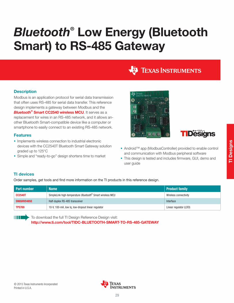
DescriptionModbus is an application protocol for serial data transmission that often uses RS-485 for serial data transfer. This reference design implements a gateway between Modbus and the Bluetooth® Smart CC2540 wireless MCU. It serves as a replacement for wires in an RS-485 network, and it allows an-other Bluetooth Smart-compatible device like a computer or smartphone to easily connect to an existing RS-485 network.
Features• Implements wireless connection to industrial electronic
devices with the CC2540T Bluetooth Smart Gateway solution graded up to 125°C
• Simple and “ready-to-go” design shortens time to market
• Android™ app (ModbusController) provided to enable control and communication with Modbus peripheral software
• This design is tested and includes firmware, GUI, demo and user guide
Bluetooth® Low Energy (Bluetooth Smart) to RS-485 Gateway
Part number Name Product family
CC2540T SimpleLink high-temperature Bluetooth® Smart wireless MCU Wireless connectivity
SN65HVD485E Half-duplex RS-485 transceiver Interface
TPS769 10-V, 100-mA, low Iq, low-dropout linear regulator Linear regulator (LDO)
To download the full TI Design Reference Design visit: http://www.ti.com/tool/TIDC-BLUETOOTH-SMART-TO-RS-485-GATEWAY
TI devicesOrder samples, get tools and find more information on the TI products in this reference design.
© 2015 Texas Instruments IncorporatedPrinted in U.S.A.
TI D
esig
ns
29

DescriptionThe CC2540 USB Dongle is a complete example of how to use the USB-enabled Bluetooth® Low Energy (BLE) Wireless MCU. The reference design can be used to enable Bluetooth Smart and Internet of Things applications on any system that contains a USB host.
Features• Simple BLE-to-USB connection – Adds BLE to an existing
product with USB• Debug header, LEDs and buttons included – Enables faster
development• It can also be used as a packet sniffer for analyzing the BLE
protocol and for software and system-level debugging (use the free tool SmartRF Packet Sniffer)
CC2540 Bluetooth® Low Energy USB Dongle Reference Design
Part number Name Product family
CC2540 SimpleLink Bluetooth® Smart wireless MCU with USB Wireless connectivity
TPS769 10-V, 100-mA, low Iq, low-dropout linear regulator Linear regulator (LDO)
To download the full TI Design Reference Design visit: http://www.ti.com/tool/TIDC-CC2540-BLE-USB
TI devicesOrder samples, get tools and find more information on the TI products in this reference design.
© 2015 Texas Instruments IncorporatedPrinted in U.S.A.
TI D
esig
ns
30

DescriptionThis reference design is a low-power wireless gas sensor solution that supports a wide array of electrochemical gas sensors. With the versatility of a configurable interface for either Bluetooth® Low Energy, ZigBee® RF4CE, 6LoWPAN or ANT this flexible and certified sensor solution is ideal for various building safety, industrial process control, mining and health care applications.
Features• Monitors wide range of gases
• Carbon monoxide, oxygen, ammonia, fluorine, chlorine dioxide … and more
• Supports 2- and 3-lead electrochemical gas sensors• Complies with FCC and IC regulatory standards• Coin-cell battery operation• Easily monitor gas concentrations via TI’s gas sensor iOS
mobile app
Gas Sensor Platform with Bluetooth® Low Energy
Part number Name Product family
CC2541 SimpleLink™ Bluetooth® Smart and proprietary wireless MCU Wireless connectivity
LM4120 Precision micropower low dropout voltage reference Voltage reference
LMP91000 Configurable AFE potentiostat for low-power chemical-sensing applications Sensor products
TPS61220 Low input voltage, 0.7-V boost converter with 5.5-μA quiescent current Converter (integrated switch)
To download the full TI Design Reference Design visit: http://www.ti.com/tool/TIDA-00056
TI devicesOrder samples, get tools and find more information on the TI products in this reference design.
© 2015 Texas Instruments IncorporatedPrinted in U.S.A.
TI D
esig
ns
31

DescriptionThe Smart Home and Energy Gateway Reference Design provides example implementation for measurement, manage-ment and communication of energy systems for smart homes and buildings. This example design is a bridge between different communication interfaces, such as Wi-Fi®, Ethernet, ZigBee® or Bluetooth®, that are commonly found in residen-tial and commercial buildings. Since objects in the house and buildings are becoming more and more connected, the gateway design needs to be flexible to accommodate differ-ent RF standards, since no single RF standard is dominating the market. This example gateway addresses this problem by supporting existing legacy RF standards (Wi-Fi, Bluetooth) and newer RF standards (ZigBee, BLE).
Features• Showcase co-existence of ZigBee, Wi-Fi, Bluetooth and NFC
(Near Field Communication) allows for simultaneous operation of the different communication profiles
• Showcase seamless profile integration for smart energy, light-ing and building automation
• Showcase bridge between HAN (Home Area Network) and LAN (Local Area Network)/WAN (Wide Area Network)
• Enables development of real-world smart home and energy gateway applications, with the use of example schematics, bill of materials, design files and links to free software package downloads
(continued)
Smart Home and Energy Gateway Reference Design
TI D
esig
ns
32

Part number Name Product family Design kits and Evaluation modules
AM3352 Sitara™ processor ARM® Cortex®-A8 core View Design Kits & Evaluation Modules
CC2530 Second-generation System-on-Chip solution for 2.4-GHz IEEE 802.15.4 / RF4CE / ZigBee SimpleLink™ solutions View Design Kits & Evaluation Modules
WL1835MOD WiLink™ 8 single-band combo 2×2 MIMO Wi-Fi, Bluetooth and Bluetooth Low Energy module Wireless Connectivity View Design Kits & Evaluation Modules
DP83848J PHYTER mini LS commercial temperature single-port 10/100 Mb/s Ethernet transceiver Ethernet View Design Kits & Evaluation Modules
SN74AVC4T774 4-bit dual-supply bus transceiver with configurable voltage translation and 3-state outputs Voltage level translation
SN74LVC04 Hex inverter Buffer/Driver/Transceiver
SN74LVC07A Hex buffer/driver with open-drain outputs Buffer/Driver/Transceiver
TLV702 300-mA, low IQ, low-dropout regulator for portables Linear regulator (LDO) View Design Kits & Evaluation Modules
TLVH431 Low-voltage adjustable precision shunt regulator Voltage reference
TPD4S012 4-channel USB ESD solution with power clamp ESD protection diodes View Design Kits & Evaluation Modules
TPS2051B Single, current-limited, power-distribution switch USB power and charging port controllers View Design Kits & Evaluation Modules
TPS51200 3-A sink/source DDR termination regulator w/ VTTREF buffered reference for DDR2, DDR3, DDR3L and DDR4 Power management View Design Kits & Evaluation Modules
TPS650250 Power management IC (PMIC) for Li-ion powered systems Power management View Design Kits & Evaluation Modules
To download the full TI Design Reference Design visit: http://www.ti.com/tool/TIEP-SMART-ENERGY-GATEWAY
TI devicesOrder samples, get tools and find more information on the TI products in this reference design.
© 2015 Texas Instruments IncorporatedPrinted in U.S.A.
Return to ToC

34
Wireless connectivity product overviews
Pro
duc
t O
verv
iew
s

The industry’s only multi-standard family with code- and pin-compatibility across:• Bluetooth® low energy (Bluetooth
Smart)• 6LoWPAN• Sub-1 GHz• ZigBee®
• RF4CE™ and • Proprietary
modes
OverviewThe SimpleLink™ ultra-low power wire-less microcontroller (MCU) platform is the broadest, lowest power and easiest
to use wireless connectivity offering in the industry for Internet of Things
(IoT) connected devices. With the capability to leverage multiple standards, cus-tomers have flexibility in
design and TI makes it easy by providing tools and soft-
ware, reference designs, com-munity support and more.
What standard fits your design?• Bluetooth Smart: Control ultra-
low power wireless solutions with a smartphone or tablet
• 6LoWPAN: Complete solution to the cloud in a wide-area mesh network using open IP standards
• Sub-1 GHz: Provides long range and reliable communication at ultra-low power
• ZigBee: Standardized stacks, pro-tocols and application profiles for robust, low-power mesh networks
• RF4CE: Two-way communication standard designed for ultra-low power input devices such as remote controls
Available products• SimpleLink 2.4-GHz multi-standard
C2650 wireless MCU: The CC2650 supports multiple 2.4 GHz standards allowing customers to leverage code compatibility across 2.4 GHz standards by downloading the cor-responding protocol stack.
• SimpleLink Bluetooth Smart CC2640 wireless MCU: The CC2640 is the lowest power Flash-based Bluetooth 4.1 solution with multi-year operation on smaller coin cells.
• SimpleLink 6LoWPAN/ZigBee CC2630 wireless MCU: The CC2630 supports large networks connecting 1,000s of nodes in homes, buildings and cities. Take advantage of easy IP and cloud connectivity through 6LowPAN operation where each device has an IPv6 address.
• TI is also launching the SimpleLink Sub-1 GHz CC1310 wireless MCU and the SimpleLink ZigBee RF4CE CC2620 wireless MCU in 2015.
Getting startedTo simplify development, TI provides a broad range of tools and software that offer flexibility between technolo-gies. All kits for 2.4-GHz operation are based on the multi-standard CC2650 wireless MCU. The CC2650DK includes two SmartRF06 evaluation boards, two CC2650 evaluation modules and can be customized with the appropriate software stacks for Bluetooth Smart, 6LoWPAN or ZigBee operation. The CC2650STK SimpleLink SensorTag is a rapid prototyping and development tool designed to shorten the design time for CC26xx development from months to hours.
SimpleLink™ Ultra-Low Power Wireless Microcontroller Platform
Key benefits• The lowest power:
• Go battery-less with energy harvesting
• Use a coin cell battery for multi-year, always-on operation
• Integrated ultra-low power sensor controller
• Industry’s only multi-standard platform:• Code- and pin-compatibility
across Bluetooth Smart, 6LoWPAN, ZigBee, Sub-1 GHz and RF4CE
• Easiest to design with:• ARM® Cortex®-M3 based MCU• TI-RTOS• Simplest RF and antenna
design• Built-in robust security• Ready-to-use protocol stacks• Tools and reference designs
Pro
duc
t O
verv
iew
s
35

Hardware
CC2650DK $299
CC2650EMK $99
CC2650STK $29
Complete 2.4-GHz hardware, software and RF development platform for Bluetooth Smart, ZigBee and 6LoWPAN
Two optimized plug-in boards to easily test RF performance with more nodes in a CC2650DK network
The EMK comes in 4×4-mm, 5×5-mm and 7×7-mm options
Low-power development kit for IoT applicationsStart sensor development in the cloud in three minutes. Expandable with debugger and DevPacks to customized your IoT application. Powered by the CC2650 wireless MCU and 10 low-power sensors
© 2015 Texas Instruments IncorporatedPrinted in U.S.A.
The platform bar and SimpleLink are trademarks of Texas Instruments. All other trademarks are the property of their respective owners.
Software
SmartRF Studio 7 Sensor Controller Studio SmartRF Flash Programmer 2 CCS Uniflash
PC application that helps designers of radio systems easily evaluate the RF-IC at an early stage in the design process
Development environment to implement sensor controller task algorithms and rapid development
PC application for programming CC26xx devices
Flash programmer with Windows® and Linux™ support
For more information on the SimpleLink ultra-low power wireless MCU platform, please visit www.ti.com/simplelinkulp
Main CPU
Sensor controller
ARM®
Cortex -M3®
Sensor controller
engine
2× Analog comparators
12-bit ADC, 200 ks/s
Constant current source
SPI / I C digital sensor IF2
2 KB SRAM
Time-to-digital converter
SimpleLink™ ULP wireless MCU platform
Up to
128 KB
Flash
cJTAG
20 KB
SRAM
8 KB
cache
ROM
DC / DC converter
General peripherals / modules
4× 32-bit timers
2× SSI (SPI, µW, TI)
Watchdog timer
TRNG
Temp. / batt. monitor
RTC
I C2
UART
I2S
10 / 15 / 31 GPIOs
AES
32 ch. µDMA
RF core2.4 GHz
Sub-1GHz
DSP modem
ADC
ADC
Digital PLL
4 KB
SRAM
ROM
Radio
controller
Application areasThe SimpleLink ultra-low power wireless MCU platform is designed for use in multiple applications including:
Block diagram
Health and Fitness
Home and Building Automation
Industrial
36

SimpleLink™ Wi-Fi® FamilyCC3100 / CC3200 Internet-on-a-chip™ Solutions
OverviewTI makes connectivity even easier with the next-generation SimpleLink Wi-Fi solutions. The product family features Internet-on-a-chip™, Wi-Fi CERTIFIED™ solutions solving industry challenges for broad embedded applications. With SimpleLink CC3100 and CC3200 pin-to-pin-compatible solutions you can:• Program applications on the industry’s first
Internet-on-a-chip solution with user- dedicated MCU
• Power Wi-Fi battery-operated designs for more than a year on two AA batteries
• Start quickly, no Wi-Fi experience needed
CC3100 Wireless Network ProcessorThe CC3100 device is a Wi-Fi, self-contained network processor with on-chip web server and embedded TCP/IP stack that connects
easily to any low-cost and low-power micro-controller (MCU) such as the MSP430F5529 or MSP430FR5969, due to a simple UART or SPI driver and host memory footprint as low as 7kB of code to reside on the MCU. Hardware design flexibility includes a 64-pin 9×9 mm QFN package or upcoming certified CC3100 module. Flexible connection methods (provisioning)
include Access Point Mode, WPS, SmartConfig™ Technology and others. On the security side, an embedded hardware cryptography engine allows establishing TLS secure Link in 200 ms.
Interfacing to any MCU, designed with low-power radio and advanced low-power modes, the SimpleLink Wi-Fi family makes sensor-to-the-cloud connectivity possible. Moreover, the solution contains several Internet protocols in ROM includ-ing mDNS, DNS, SSL/TLS and HTTP server.
CC3200 Wireless MCUThe SimpleLink Wi-Fi CC3200 solution capitalizes on the CC3100 benefits and integrates an 80-MHz ARM® Cortex®-M4 MCU and peripherals enabling application develop-ment with a Wi-Fi CERTIFIED device or module. Developers can fully access the MCU portion with more than 200kB of application code fully independent from the Wi-Fi processing. The peripheral set includes parallel camera,
I2S audio, SDMMC, ADC, SPI, UART, I2C, PWM, I/Os, built-in power management and RTC enabling connection to the cloud.
CC3200 certified modules, coming soon, provide easier Wi-Fi integration by lowering manufacturing costs, reducing development time and simplifying procurement and certifica-tion. The modules have complete antenna reference designs for streamlined integration.
Software and SupportBoth CC3100 and CC3200 solutions are sup-ported by a software development kit (SDK) including software drivers, sample applica-tions, API guide, user documentation and a world-class support E2E™ community. On the integrated Cortex-M4, all sample applications in the SDK are supported with Code Composer Studio™ Integrated Development Environment and no RTOS. A few of the applications support IAR, GCC, Free RTOS, TI-RTOS. Example applications:
• Internet-on-a-chip sample applications • Email from SimpleLink Wi-Fi solution • Information Center – get time and weather
from Internet • http server – host a web page on
SimpleLink Wi-Fi solution • XMPP – Instant Message chat client • Serial interface
• Wi-Fi sample apps • Easy Wi-Fi configuration • Station, AP modes • TCP/UDP • Security – Enterprise/Personal, TLS/SSL
• MCU peripheral samples apps
VCC
32-KHzXTAL
MCUCC3100Network
Processor
32 KHz
Enable
IRQ
SPI or
UART
40-MHzXTAL
SerialFlash
Fast Parallel
SPI
ROM
PE
RIP
HE
RA
L IN
TE
RFA
CE
S
RAM
UART
UART
Timers
GPIOs
Oscillators
I C2
SD/MMC
ADCBAT Monitor
DC2DC
Hibernate RTC PWM
I S/PCM2
AN
AL
OG
SY
ST
EM
PO
WE
R
MA
NA
GE
ME
NT
JTAG
ARM
Cortex -M4
80 MHz
®
®
Wi-Fi Network Processor®
Save time and resources developing with CC3100 and CC3200 Wi-Fi® CERTIFIED™ chips and modules
Pro
duc
t O
verv
iew
s
37
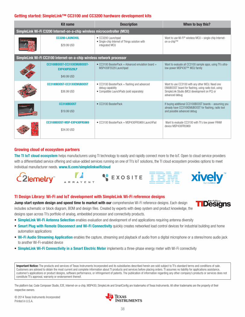
Getting started: SimpleLink™ CC3100 and CC3200 hardware development kits
Kit name Description When to buy this?
SimpleLink Wi-Fi C3200 Internet-on-a-chip wireless microcontroller (MCU)
CC3200-LAUNCHXL
$29.99 USD
• CC3200 Launchpad• Single-chip Internet of Things solution with
integrated MCU
Want to use Wi-Fi® wireless MCU – single-chip Internet-on-a-chip™
SimpleLink Wi-Fi CC3100 Internet-on-a-chip wireless network processor
CC3100BOOST-CC31XXEMUBOOST-
EXP430F5529LP
$49.99 USD
• CC3100 BoosterPack + Advanced emulation board + MSP430F5529 Launchpad
Want to evaluate all CC3100 sample apps, using TI’s ultra-low-power MSP430™ MCU family
CC3100BOOST-CC31XXEMUBOOST
$36.99 USD
• CC3100 BoosterPack + flashing and advanced debug capability
• Compatible LaunchPads (sold separately)
Want to use CC3100 with any other MCU. Need one EMUBOOST board for flashing, using radio tool, using SimpleLink Studio (MCU development on PC) or advanced debug
CC3100BOOST
$19.99 USD
• CC3100 BoosterPack If buying additional CC3100BOOST boards – assuming you already have CC31XXEMUBOOST for flashing, radio tool and possible advanced debug
CC3100BOOST-MSP-EXP430FR5969
$34.00 USD
• CC3100 BoosterPack + MSP430FR5969 LaunchPad Want to evaluate CC3100 with TI's low power FRAM device MSP430FR5969
Growing cloud of ecosystem partnersThe TI IoT cloud ecosystem helps manufacturers using TI technology to easily and rapidly connect more to the IoT. Open to cloud service providers with a differentiated service offering and value-added services running on one of TI’s IoT solutions, the TI cloud ecosystem provides options to meet individual manufacturer needs. www.ti.com/simplelinkwificloud
TI Design Library: Wi-Fi and IoT development with SimpleLink Wi-Fi reference designsJump start system design and speed time to market with our comprehensive Wi-Fi reference designs. Each design includes schematic or block diagram, BOM and design files. Created by experts with deep system and product knowledge, the designs span across TI’s portfolio of analog, embedded processor and connectivity products.
• SimpleLink Wi-Fi Antenna Selection enables evaluation and development of end applications requiring antenna diversity
• Smart Plug with Remote Disconnect and Wi-Fi Connectivity quickly creates networked load control devices for industrial building and home automation applications
• Wi-Fi Audio Streaming Application enables the capture, streaming and playback of audio from a digital microphone or a stereo/mono audio jack to another Wi-Fi-enabled device
• SimpleLink Wi-Fi Connectivity in a Smart Electric Meter implements a three-phase energy meter with Wi-Fi connectivity
© 2014 Texas Instruments IncorporatedPrinted in U.S.A.
The platform bar, Code Composer Studio, E2E, Internet-on-a-chip, MSP430, SimpleLink and SmartConfig are trademarks of Texas Instruments. All other trademarks are the property of their respective owners.
SWRB034B
Important Notice: The products and services of Texas Instruments Incorporated and its subsidiaries described herein are sold subject to TI’s standard terms and conditions of sale. Customers are advised to obtain the most current and complete information about TI products and services before placing orders. TI assumes no liability for applications assistance, customer’s applications or product designs, software performance, or infringement of patents. The publication of information regarding any other company’s products or services does not constitute TI’s approval, warranty or endorsement thereof.
38
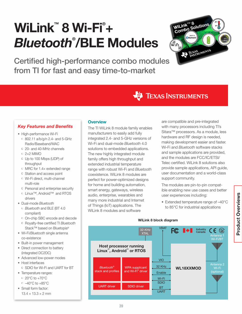
Certified high-performance combo modules from TI for fast and easy time-to-market
OverviewThe TI WiLink 8 module family enables manufacturers to easily add fully integrated 2.4- and 5-GHz versions of Wi-Fi and dual-mode Bluetooth 4.0 solutions to embedded applications. The new highly integrated module family offers high throughput and extended industrial temperature range with robust Wi-Fi and Bluetooth coexistence. WiLink 8 modules are perfect for power-optimized designs for home and building automation, smart energy, gateways, wireless audio, enterprise, wearables and many more industrial and Internet of Things (IoT) applications. The WiLink 8 modules and software
are compatible and pre-integrated with many processors including TI’s Sitara™ processors. As a module, less hardware and RF design is needed, making development easier and faster. Wi-Fi and Bluetooth software stacks and sample applications are provided, and the modules are FCC/IC/ETSI/Telec certified. WiLink 8 solutions also provide sample applications, API guide, user documentation and a world-class support community.
The modules are pin-to-pin compat-ible enabling new use cases and better user experiences including:
• Extended temperature range of –40°C to 85°C for industrial applications
VBAT
WL18XXMOD
Antenna 1Wi-Fi/BT
Antenna 2Wi-Fi
(optional)
VIO
32 KHz
Enable
Wi-Fi
SDIO
BT
UART
32-KHzXTAL
Host processor running
Linux , Android™™
or RTOS
Bluetooth®
stack and profilesWPA supplicant
and Wi-Fi driver®
UART driver SDIO driver
WiLink 8 block diagram
WiLink™ 8 Wi-Fi®+ Bluetooth®/BLE Modules
Key Features and Benefits
• High-performance Wi-Fi• 802.11 a/b/g/n 2.4- and 5-GHz
Radio/Baseband/MAC• 20- and 40-MHz channels• 2×2 MIMO• Up to 100 Mbps (UDP) of
throughput• MRC for 1.4× extended range• Station and access point• Wi-Fi direct, multi-channel
multi-role• Personal and enterprise security• Linux™, Android™ and RTOS
drivers• Dual-mode Bluetooth
• Bluetooth and BLE (BT 4.0 compliant)
• On-chip SBC encode and decode• Royalty-free certified TI Bluetooth
Stack™ based on Bluetopia®
• Wi-Fi/Bluetooth single antenna co-existence
• Built-in power management• Direct connection to battery
(integrated DC2DC)• Advanced low-power modes• Host interfaces
• SDIO for Wi-Fi and UART for BT• Temperature ranges:
• 20°C to +70°C • –40°C to +85°C• Small form factor:
13.4 × 13.3 × 2 mm
Pro
duc
t O
verv
iew
s
39

© 2014 Texas Instruments IncorporatedPrinted in U.S.A.
The platform bar, Sitara, SmartConfig and WiLink are trademarks of Texas Instruments. All other trademarks are the property of their respective owners.
WiLink™ 8 Wi-Fi®+ Bluetooth®/BLE Modules
Other tools• TI provides a fully integrated and
validated WiLink 8 add-on software for Sitara AM335x Linux™ ezSDK – www.ti.com/wilink8
• TI’s unique SmartConfig™ technol-ogy is a one-step Wi-Fi setup process that allows multiple in-home devices to connect to Wi-Fi networks quickly and efficiently – www.ti.com/tool/smartconfig
WiLink resources• Learn more:
www.ti.com/wilink8
• E2E Forum: www.ti.com/wiconforum
• WiLink 8 Wiki: www.ti.com/wilink8wiki
Product NumberWi-Fi®
Bluetooth v4.0 Bluetooth low
energyIndustrial
temperature2.4 GHz 5 GHz MIMO
WL1801MOD •WL1805MOD • •WL1807MOD • • • •WL1831MOD • •WL1835MOD • • •WL1837MOD • • • • •
TI Modules
Important Notice: The products and services of Texas Instruments Incorporated and its subsidiaries described herein are sold subject to TI’s standard terms and conditions of sale. Customers are advised to obtain the most current and complete information about TI products and services before placing orders. TI assumes no liability for applications assistance, customer’s applications or product designs, software performance, or infringement of patents. The publication of information regarding any other company’s products or services does not constitute TI’s approval, warranty or endorsement thereof.
Product Number Description Availability
WL1835MODCOM8 The 2.4-GHz WL1835-based evaluation board is compatible with the Sitara™ AM335x and AM437x EVMs as well as several other TI EVMs and reference designs
TI eStore and authorized distributors
WL1835MOD Cape WiLink 8 module-based cape offered by CircuitCo for fast development with BeagleBone Black and BeagleBone open source computer
BoardZoo.com and CircuitCo distributors
WL1837MODCOM8 The 5-GHz WL1837-based evaluation board is compatible with Sitara AM335x and AM437xEVMs as well as several other TI EVMs and reference designs
TI eStore and authorized distributors
Development Tools
• 5-GHz module for high-performance solutions in a less noisy frequency band
• Wi-Fi, Bluetooth and ZigBee® coex-istence for Smart energy and home gateways
• 1.4× the range and up to 100 Mbps throughput with WiLink 8 MRC
(maximal ratio combining) and MIMO (multiple-input and multiple-output) technology
• Low-power applications with low idle connect current consumption
• Audio streaming with both Wi-Fi and dual-mode Bluetooth/Bluetooth low energy
Applications• Internet of Things• Industrial and home automation• Home electronics• Home appliances and white goods• Gateways• Wireless audio• Video camera and security• Wearables
40

OverviewTI single- and dual-mode CC256x solutions are complete Bluetooth® BR/EDR/LE HCI or Bluetooth + Bluetooth Low Energy solutions that reduce design effort and enable fast time to market.
A royalty-free software Bluetooth stack available from TI is pre-integrated with TI’s MSP430™ and ARM® Cortex®-M4 MCUs. The stack is also available for MFi solutions and on other MCUs. Examples of profiles sup-ported today include: serial port profile (SPP), human interface device (HID), A2DP (Advanced Audio Distribution Profile), AVRCP (Audio/Video Remote Control Profile) and several BLE profiles (profiles can vary based on the sup-ported MCU).
In addition to software, reference designs are available with a low BOM cost. For example, TI’s Audio Sink solu-tion uses the Bluetooth® device for audio processing, an MSP430™, audio DAC and USB charger. TI’s Audio Source solution is also available. For more information, visit TI Designs.
TI Bluetooth® CC256x SolutionsDual-mode Bluetooth 4.1 controller available in certified modules with integrated audio capabilities
Key Features• Single-chip Bluetooth solution integrating Bluetooth
Basic Rate (BR)/Enhanced Data Rate (EDR)/Low Energy (LE) features fully compliant with the Bluetooth 4.1 specification up to the HCI layer
• BR/EDR features include: • CC2560 provides an assisted mode for HFP1.6
wideband speech (WBS) profile or A2DP profile to reduce host processing and power
• LE supports up to 10 CC2564 simultaneous connections
• Flexibility for easy stack integration and validation into various microcontrollers, such as MSP430 and ARM Cortex-M4 MCUs
• Highly optimized for low-cost designs: • Package footprint: 76 pins, 0.6-mm pitch,
8.10-mm × 8.10-mm mrQFN• Best-in-class Bluetooth (RF) performance
(TX power, RX sensitivity, blocking) • Class 1.5 TX power up to +12 dBm • Provides longer range, including 2× range over
ther Bluetooth low energy-only solutions• Advanced power management for extended battery
life and ease of design• Physical interfaces: • Standard HCI over H4 UART (4 wire) • Standard HCI over H5 UART (2 wire) • Fully programmable digital PCM-I2S codec
interface
Benefits• Best-in-class link budget extends application range• Simplified hardware and software development• Reduced development time and costs• Enables simultaneous operations of Bluetooth
with Bluetooth low energy
www.ti.com/bluetooth
MSP430or
™
Other MCU
32-KHz
UART
Clock
Filter
26-MHzClock
CC256x
CC256x block diagram
Pro
duc
t O
verv
iew
s
41

© 2015 Texas Instruments Incorporated
The platform bar, E2E and MSP430 are trademarks of Texas Instruments. All other trademarks are the property of their respective owners.
Applications• Cable replacement
• Smart watches, activity trackers
• Mobile device accessories
• Industrial control
• Audio streaming solutions
• Point of sale
Bluetooth® CC256x Resources• Learn more at: www.ti.com/bluetooth
• E2E™ Forum: www.ti.com/wiconforum
• CC256x Wiki: www.ti.com/cc2564wiki
Product Number Description Availability
CC256x modules from TI TI-certified modules based on the CC2564 devices Available through TI and TI authorized distributors
CC2564MODEM CC2564 Module Evaluation board Intended for evaluation purposes of the CC2564 module. Works with processor platforms such as TI’s ultra-low-power MSP430 and the performance TM4C ARM® Cortex®-MF microcontrollers.
TI Store and authorized distributors
Bluetooth and MSP430™ Audio Sink Reference Design
Enables Bluetooth audio (SBC encode/decode) with CC2560 and the ultra-low power MSP430F5229 and digital input speaker amplifier (TAS2505) and USB charge manage-ment device (BQ24055). Reference design is a cost-effective audio implementation, with full design files provided for application and end product development. Software supported includes TI Bluetooth stack (certified and royalty free) based on Bluetopia.
Download at TI Designs
Boards are orderable through TI Store
Bluetooth and MSP430 Audio Source Reference Design
Enables Bluetooth audio (SBC encode/decode) with CC2560 and the ultra-low power MSP430F5229 and digital DAC plus USB charge management device (BQ24055). Reference design is a cost-effective audio implementation, with full design files provided for applica-tion and end product development. Software supported includes TI Bluetooth stack (certified and royalty free) based on Bluetopia.
Download at TI Designs
Boards are orderable through TI Store
CC256x BoosterPack Bluetooth BoosterPack evaluation kit has flexibility to work with ultra-low power microcontrollers such as the TI MSP430 and TM4C Series LaunchPad evaluation kits
Coming soon: Boards will be orderable through TI Store
CC256xQFNEM CC256x Bluetooth® / dual-mode QFN device evaluation module TI Store and authorized distributors
Development Tools and Software
CC256x Products
Devices/Modules Description
Technology supported Assisted modes
BR/EDR LE Ant™ HFP 1.6 (WBS) A2DP
CC2560 Bluetooth® 4.1 (with EDR) • • •
CC2564*Bluetooth 4.1 + BLE • • • •Bluetooth 4.1 + ANT • • • •
* The device does not support simultaneous operation of LE, ANT or assisted modes. Any of these modes can run simultaneous to Bluetooth BR/EDR.
42

Product
Folder
Sample &Buy
Technical
Documents
Tools &
Software
Support &Community
CC2540TSWRS172 –JULY 2014
SimpleLink™ CC2540T 2.4-GHz Bluetooth® Low Energy Wireless MCU1 Device Overview
1.1 Features1
• True Single-Chip BLE Solution: CC2540T Can Run • PeripheralsBoth Application and BLE Protocol Stack, Includes – 12-Bit ADC with Eight Channels andPeripherals to Interface with Wide Range of Configurable ResolutionSensors, and so forth. – Integrated Ultralow-Power Comparator
• Operating Temperature up to 125°C – General-Purpose Timers (One 16-Bit, Two 8-Bit)• 6-mm × 6-mm Package – 21 General-Purpose I/O (GPIO) Pins (19×4 mA,• RF 2×20 mA)
– Bluetooth Low Energy Technology Compatible – 32-kHz Sleep Timer with Capture– Excellent Link Budget (up to 97 dB), Enabling – Two Powerful USARTs with Support for Several
Long-Range Applications Without External Front Serial ProtocolsEnd – Full-Speed USB Interface
– Accurate Digital Received Signal-Strength – IR Generation CircuitryIndicator (RSSI) – Powerful Five-Channel DMA
– Suitable for Systems Targeting Compliance with – AES Security CoprocessorWorldwide Radio Frequency Regulations: ETSI– Battery Monitor and Temperature SensorEN 300 328 and EN 300 440 Class 2 (Europe),– Each CC2540T Contains a Unique 48-Bit IEEEFCC CFR47 Part 15 (US), and ARIB STD-T66
Address(Japan)• Bluetooth v4.0 Compliant Protocol Stack for• Layout
Single-Mode BLE Solution– Few External Components– Complete Power-Optimized Stack, Including– Reference Design Provided
Controller and Host– 6-mm × 6-mm QFN40 Package• GAP – Central, Peripheral, Observer, or• Low Power Broadcaster (Including Combination Roles)
– Active Mode RX Down to 19.6 mA • ATT / GATT – Client and Server– Active Mode TX (–6 dBm): 24 mA • SMP – AES-128 Encryption and Decryption– Power Mode 1 (3-μs Wake-Up): 235 μA • L2CAP– Power Mode 2 (Sleep Timer On): 0.9 μA – Sample Applications and Profiles– Power Mode 3 (External Interrupts): 0.4 μA • Generic Applications for GAP Central and– Wide Supply Voltage Range (2 V–3.6 V) Peripheral Roles– Full RAM and Register Retention in All Power • Proximity, Accelerometer, Simple Keys, and
Modes Battery GATT Services• TPS62730 Compatible – Multiple Configuration Options
Low Power in Active Mode • Single-Chip Configuration, Allowing– RX Down to 15.8 mA (3-V Supply) Application to Run on CC2540T– TX (–6 dBm): 18.6 mA (3-V Supply) • Network Processor Interface for Applications
• Microcontroller Running on an External Microcontroller– High-Performance and Low-Power 8051 – BTool – Windows PC Application for Evaluation,
Microcontroller Core Development, and Test– 256-KB In-System-Programmable Flash • Development Tools– 8-KB SRAM – CC2540T Mini Development Kit
– SmartRF™ Software– Supported by IAR Embedded Workbench™
Software for 8051
1
An IMPORTANT NOTICE at the end of this data sheet addresses availability, warranty, changes, use in safety-critical applications,intellectual property matters and other important disclaimers. PRODUCTION DATA.
Pro
duc
t O
verv
iew
s
43

CC2540TSWRS172 –JULY 2014 www.ti.com
1.2 Applications• 2.4-GHz Bluetooth Low Energy Systems • Power Tools• Lighting • Maintenance• Motor Monitoring • Wireless HMI and Remote Display• Proximity Sensing • USB Dongles• Cable Replacement • Smart Phone Connectivity
1.3 DescriptionThe CC2540T is a cost-effective, low-power, true wireless MCU for Bluetooth low energy applications. Itenables robust BLE master or slave nodes to be built with very low total bill-of-material costs, and canoperate up to 125°C. The CC2540T combines an excellent RF transceiver with an industry-standardenhanced 8051 MCU, in-system programmable flash memory, 8-KB RAM, and many other powerfulsupporting features and peripherals. The CC2540T is suitable for systems where very low powerconsumption is required. Very low-power sleep modes are available. Short transition times betweenoperating modes further enable low power consumption.
Combined with the Bluetooth low energy protocol stack from Texas Instruments, the CC2540TF256 formsthe market’s most flexible and cost-effective single-mode Bluetooth low energy solution.
Table 1-1. Device Information(1)
PART NUMBER PACKAGE BODY SIZECC2540TF256RHAR RHA (40) 6.00 mm × 6.00 mmCC2540TF256RHAT RHA (40) 6.00 mm × 6.00 mm
(1) For more information, see Section 8, Mechanical Packaging and Orderable Information.
2 Device Overview Copyright © 2014, Texas Instruments IncorporatedSubmit Documentation FeedbackProduct Folder Links: CC2540T
44

RESETWATCHDOG
TIMER
IRQ CTRL FLASH CTRL
DEBUGINTERFACE
CLOCK MUXand
CALIBRATION
DMA
8051 CPUCORE
32-MHz
CRYSTAL OSC
OP-AMP
32.768-kHz
CRYSTAL OSC
HIGH-
SPEED
RC-OSC POWER MANAGEMENT CONTROLLER
USART 0
USB
USART 1
TIMER 1 (16-Bit)
TIMER 3 (8-Bit)
TIMER 4 (8-Bit)
TIMER 2(BLE LL TIMER)
FLASH
FIFOCTRL 1 KB SRAM
ON-CHIP VOLTAGE
REGULATOR
POWER-ON RESET
BROWN OUT
VDD (2 V–3.6 V)
DCOUPLRESET_N
XOSC_Q2
XOSC_Q1
P2_4
P1_7
P0_7
P2_3
P1_6
P0_6
P2_2
P1_5
P0_5
P1_2
P0_2
P2_1
P1_4
P0_4
P1_1
P0_1
P2_0
P1_3
P0_3
P1_0
P0_0
MODULATORDEMODULATOR
RECEIVE TRANSMIT
FR
EQ
UE
NC
Y
SY
NT
HE
SIZ
ER
SY
NT
H
RF_P RF_N
B0301-05
RADIO REGISTERS
SF
R B
us
SF
R B
us
��
ADC
AUDIO/DC
AESENCRYPTION
ANDDECRYPTION
MEMORYARBITRATOR FLASH
UNIFIED
SFR
IRAM
XRAM
PDATA
SLEEP TIMER
32-kHz
RC-OSC
I/O
CO
NT
RO
LL
ER
DIGITAL
ANALOG
MIXED
ANALOG COMPARATOR
USB_N
USB_P
Radio
Arb
iter
Link Layer Engine
CC2540Twww.ti.com SWRS172 –JULY 2014
1.4 Functional Block DiagramFigure 1-1 shows the functional block diagram of the device.
Figure 1-1. Functional Block Diagram
Copyright © 2014, Texas Instruments Incorporated Device Overview 3Submit Documentation FeedbackProduct Folder Links: CC2540T
Pro
duc
t O
verv
iew
s
45
SWRY016
Return to ToC

IMPORTANT NOTICE
Texas Instruments Incorporated and its subsidiaries (TI) reserve the right to make corrections, enhancements, improvements and otherchanges to its semiconductor products and services per JESD46, latest issue, and to discontinue any product or service per JESD48, latestissue. Buyers should obtain the latest relevant information before placing orders and should verify that such information is current andcomplete. All semiconductor products (also referred to herein as “components”) are sold subject to TI’s terms and conditions of salesupplied at the time of order acknowledgment.TI warrants performance of its components to the specifications applicable at the time of sale, in accordance with the warranty in TI’s termsand conditions of sale of semiconductor products. Testing and other quality control techniques are used to the extent TI deems necessaryto support this warranty. Except where mandated by applicable law, testing of all parameters of each component is not necessarilyperformed.TI assumes no liability for applications assistance or the design of Buyers’ products. Buyers are responsible for their products andapplications using TI components. To minimize the risks associated with Buyers’ products and applications, Buyers should provideadequate design and operating safeguards.TI does not warrant or represent that any license, either express or implied, is granted under any patent right, copyright, mask work right, orother intellectual property right relating to any combination, machine, or process in which TI components or services are used. Informationpublished by TI regarding third-party products or services does not constitute a license to use such products or services or a warranty orendorsement thereof. Use of such information may require a license from a third party under the patents or other intellectual property of thethird party, or a license from TI under the patents or other intellectual property of TI.Reproduction of significant portions of TI information in TI data books or data sheets is permissible only if reproduction is without alterationand is accompanied by all associated warranties, conditions, limitations, and notices. TI is not responsible or liable for such altereddocumentation. Information of third parties may be subject to additional restrictions.Resale of TI components or services with statements different from or beyond the parameters stated by TI for that component or servicevoids all express and any implied warranties for the associated TI component or service and is an unfair and deceptive business practice.TI is not responsible or liable for any such statements.Buyer acknowledges and agrees that it is solely responsible for compliance with all legal, regulatory and safety-related requirementsconcerning its products, and any use of TI components in its applications, notwithstanding any applications-related information or supportthat may be provided by TI. Buyer represents and agrees that it has all the necessary expertise to create and implement safeguards whichanticipate dangerous consequences of failures, monitor failures and their consequences, lessen the likelihood of failures that might causeharm and take appropriate remedial actions. Buyer will fully indemnify TI and its representatives against any damages arising out of the useof any TI components in safety-critical applications.In some cases, TI components may be promoted specifically to facilitate safety-related applications. With such components, TI’s goal is tohelp enable customers to design and create their own end-product solutions that meet applicable functional safety standards andrequirements. Nonetheless, such components are subject to these terms.No TI components are authorized for use in FDA Class III (or similar life-critical medical equipment) unless authorized officers of the partieshave executed a special agreement specifically governing such use.Only those TI components which TI has specifically designated as military grade or “enhanced plastic” are designed and intended for use inmilitary/aerospace applications or environments. Buyer acknowledges and agrees that any military or aerospace use of TI componentswhich have not been so designated is solely at the Buyer's risk, and that Buyer is solely responsible for compliance with all legal andregulatory requirements in connection with such use.TI has specifically designated certain components as meeting ISO/TS16949 requirements, mainly for automotive use. In any case of use ofnon-designated products, TI will not be responsible for any failure to meet ISO/TS16949.
Products ApplicationsAudio www.ti.com/audio Automotive and Transportation www.ti.com/automotiveAmplifiers amplifier.ti.com Communications and Telecom www.ti.com/communicationsData Converters dataconverter.ti.com Computers and Peripherals www.ti.com/computersDLP® Products www.dlp.com Consumer Electronics www.ti.com/consumer-appsDSP dsp.ti.com Energy and Lighting www.ti.com/energyClocks and Timers www.ti.com/clocks Industrial www.ti.com/industrialInterface interface.ti.com Medical www.ti.com/medicalLogic logic.ti.com Security www.ti.com/securityPower Mgmt power.ti.com Space, Avionics and Defense www.ti.com/space-avionics-defenseMicrocontrollers microcontroller.ti.com Video and Imaging www.ti.com/videoRFID www.ti-rfid.comOMAP Applications Processors www.ti.com/omap TI E2E Community e2e.ti.comWireless Connectivity www.ti.com/wirelessconnectivity
Mailing Address: Texas Instruments, Post Office Box 655303, Dallas, Texas 75265Copyright © 2015, Texas Instruments Incorporated