understanding the complexities of designing diaphragms · pdf file ·...
TRANSCRIPT

Understanding the Complexities of Designing Diaphragms in Buildings for Earthquakes
Des K. BullHolmes Consulting Group Ltd

2
Function of Diaphragms
1. Relatively thin but stiff horizontal structural systems which transmit in-plane lateral forces to, or between, vertical lateral force resisting elements.
2. The diaphragms tie the whole structure together.

3

4
Forces in diaphragms under earthquakes
• ‘Inertia’ forces– Inertia at a particular floor
• ‘Transfer’ forces– Forces develop between primary lateral
force resisting structures– These forces are often very large.
Force distribution in a floor diaphragm = Inertia + Transfer forces

5
Forces in diaphragm (cont.)
• Inertia and “transfer” forces are COUPLED in the analysis.
– through stiffness and deformation compatibility of the diaphragms and vertical structural systems.
• CAN’T determine distribution of “transfer” forces or inertia in isolation.

6
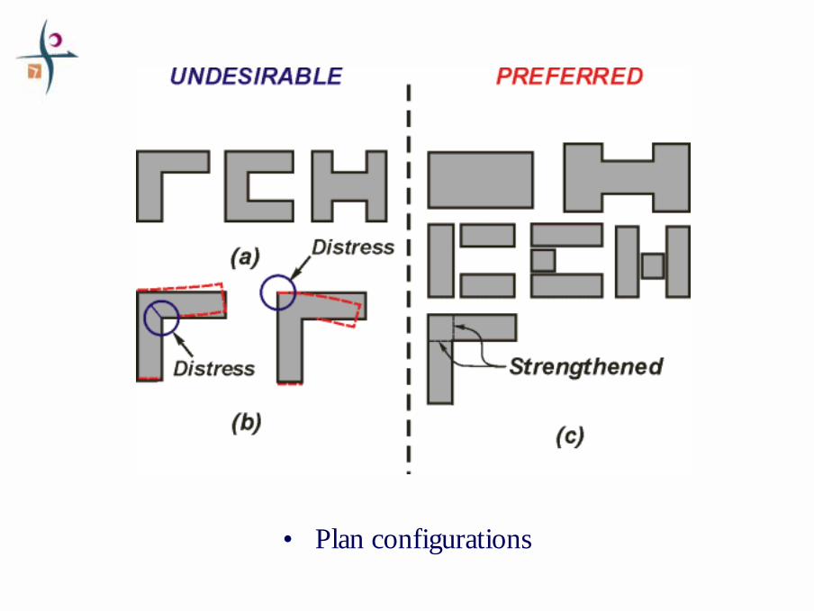
Floor plan configuration issues
7
• Plan configurations
8
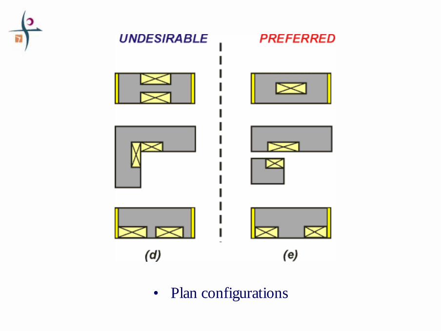
• Plan configurations
9
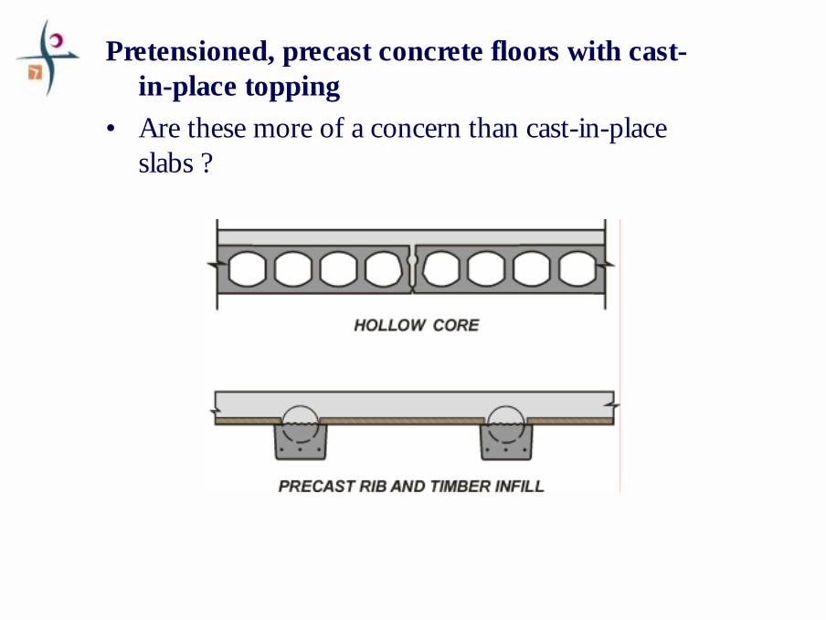
Pretensioned, precast concrete floors with cast-in-place topping
• Are these more of a concern than cast-in-place slabs ?

10
Pretensioned, precast concrete floors with cast-in-place topping

11
Structural Behaviour of Diaphragms

12
Beam Analogy

13
Openings in diaphragms and “Strut & Tie” methods
• “Strut & Tie”– Advantages over the simple Beam or
Tied Arch approach

14
Openings in diaphragms and “Strut & Tie” methods
Diagonal compression fields

15
Openings in diaphragms and “Strut & Tie” methods
Load paths in a section of floor: “micro strut & tie” solution

16
Openings in diaphragms and “Strut & Tie” methods
Diagonal tension fields

17
“Beam” or “Tied Arch” or “Strut & Tie” ?
– simple model– Provision of “tie” reinforcement

18
“Drag Bars” or “Collectors”

19
“Strut & Tie” with “drag” bars
A bit complex?

20
“Drag Bars” or “Collectors”

21
Diaphragms: Force distribution and detailing
EQF i : floor, beams, columns and cladding
Floor plate

22
EQF i : floor, beams, columns and cladding
Inertia effects, distributed across the floor
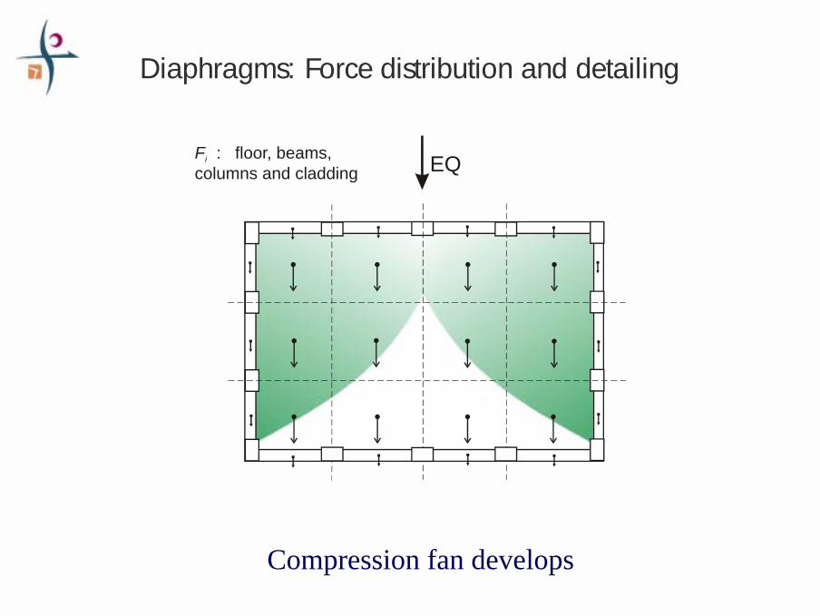
Diaphragms: Force distribution and detailing
23
EQF i : floor, beams, columns and cladding
Compression fan develops
Diaphragms: Force distribution and detailing

24
EQF i : floor, beams, columns and cladding
C C
C’
Sketch in the centres of compression: struts of a truss
Diaphragms: Force distribution and detailing

25
Note: the tie T is connected at the mid points of the beams
• more later
EQF i : floor, beams, columns and cladding
C C
C’
T
Diaphragms: Force distribution and detailing

26
EQF i : floor, beams, columns and cladding
C C
C’
T
Part of the floor (mauve) wants to “fall out” of the building
Diaphragms: Force distribution and detailing

27
EQF i : floor, beams, columns and cladding
C C
C’
T
Must tie this part back in to the truss or arch (dotted red ties)
Diaphragms: Force distribution and detailing

28
Alternatively: use secondary beams as ties/chords and make smaller struts to collect on these ties
EQF i : floor, beams, columns and cladding
C C
C’
T
Diaphragms: Force distribution and detailing

29
Or, combine the secondary beams withthe floor reinforcement acting as ties
EQF i : floor, beams, columns and cladding
C C
C’
T
Diaphragms: Force distribution and detailing

30
EQF i : floor, beams, columns and cladding
C C
C’
More struts, closer to the fan compression field
Diaphragms: Force distribution and detailing

31
Diaphragms: Forces
EQF i : floor, beams, columns and cladding
C C
C’
T
Struts and ties
T is smallerTo get other ties, requires some cracking and yielding within the floor: “redistribution of actions”

32
Issues for Diaphragms when resisting Earthquakes

33

34
Deformation modes with beam elongation
(a) Beam plastic hinge rotates to allow for beam elongation (10 – 50 mm)
Bea
m e
long
atio
n
Beam elongation
Loss
of
sup
por
t pos
sible
ove
r thi
s re
gio
n
Mode 1

35
Deformation modes with beam elongation
(b) Entire beam rotates to allow for beam elongation (10 – 50 mm)
Beam elongation
Bea
m e
long
atio
n
Loss
o
f sup
po
rt p
oss
ible
ove
r thi
s re
gio
n
Mode 2

36
Delamination of topping from hollowcore units
South
North
Plan View

37
Diaphragms: Connections or Nodes of the Struts and Ties
Column-Beam Node: Traditional view• Higher compressive stress - smaller contact surface

38
Diaphragms: Connections or Nodes of the Struts and Ties
Column-Beam Node
• Potentially large plasticity demands in Ties

39
Diaphragms: Connections or Nodes of the Struts and Ties
Node locations (where the struts and ties meet):
• Mid-point of beams– these points are relatively undamaged by
ductile frame action– Keep TIE steel away from primary beams
because this steel can be included in the tension flange (negative moment, typ.)

40
Diaphragms: Connections or Nodes of the Struts and Ties
Floor-Beam Node• Distributed node - keeps compressive stresses down

41
Diaphragms: Connections or Nodes of the Struts and Ties
Floor-Beam Node• Distributed node - keeps compressive stresses down

42
NZS 3101:1995 requires:
Tension component

43
Alternative layout of reinforcement for column tie

44
Detailing for integrity

45
Detailing for integrity

46
Determining forces in Diaphragms resulting from Earthquakes

47
Diaphragms: Forces
‘Inertia’ & ‘Transfer’ forces are COUPLED– These can not be treated in isolation.
• Some analysis methods:
Equivalent Static Analysis (ESA)
• You have equilibrium (magnitudes and directions of the applied forces at the boundary of the diaphragm).
• If the TIES are connected correctly, this mitigates the coarseness of ESA.
Fi

48
Diaphragms: Forces
Fi
Equivalent Static Analysis (ESA)
Maxima Envelope of Floor Accelerations
(DR 902 Parts)
Fi
Peak Ground Accn.

49
Diaphragms: Forces
‘Inertia’ & ‘Transfer’ forcesModal Analysis
WON’T work
• you DO NOT have equilibrium.
– Or model the diaphragm in the analysis model ?
50
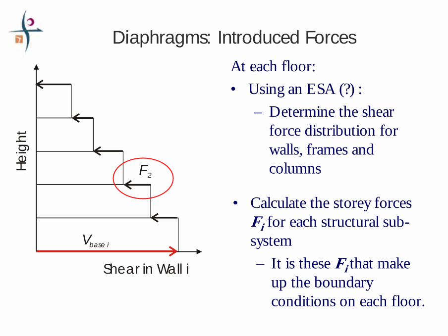
Diaphragms: Introduced Forces
At each floor:• Using an ESA (?) :
– Determine the shear force distribution for walls, frames and columnsF2
Vbase i
He
ight
Shear in Wall i
• Calculate the storey forces Fi for each structural sub-system– It is these Fi that make
up the boundary conditions on each floor.

51
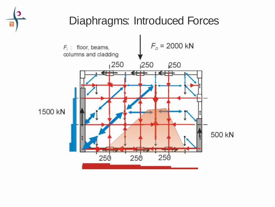
Diaphragms: Introduced Forces
Actions on the diaphragm: ESA
1500 kN
FD = 2000 kN
500 kN
F i : floor, beams, columns and cladding
250 250 250
250 250 250Inertia = 165 kN

52
Diaphragms: Introduced Forces
1500 kN
FD = 2000 kN
500 kN
F i : floor, beams, columns and cladding
250 250 250
250 250 250
≅ 500 kN≅ 1500 kN
53
Diaphragms: Introduced Forces
54
Conclusions: Issues
• Strut and Tie method is more versatile than the Beam or Tied Arch approach.
• Diaphragm will be damaged locally and may need some limited redistribution of internal forces.– Detailing of the floors to ensure integrity of the floor is
essential:• Maintenance of load paths• Continued support of gravity
55
Conclusions: Issues
• Estimating magnitudes of the inter-related inertia and “transfer” forces requires further study:– A type of Equivalent Static Analysis that
generates the deformations of the structure (induces “transfer” forces) while producing reasonable magnitudes of inertia is highly desirable for desk-top design.

56