understanding functional safety management methods ... · understanding functional safety...
TRANSCRIPT

Understanding Functional Safety Management Methods Evolution for Tomorrow’s Civil and
Military Aircraft Development and Safety Assessment
Dr. Daniel P. SchrageProfessor and Director, Vertical Lift
Research Center of Excellence (VLRCOE)School of AE, Georgia Tech
Tutorial Outline
• Background on Instructor• Part 1: Overview and History of Functional Safety Management
• Brief Review of its Application in Different Domains
• Part 2: Evolution of Functional Safety Management for Civil Aircraft and Systems to its Current and Future Global Application
• Why its Application for Military Aircraft and UAS has been difficult• What needs to be done for Future Vertical Lift (FVL) and UAS
• Part 3: Example Case Studies from Safety By Design and Flight Certification Course

Background on Instructor: Dr. Daniel P. Schrage, Georgia Tech• Education
• BS Engineering, USMA, West Point, 1967• MS Aerospace Engineering, Georgia Tech, 1974• MA Business Administration, Webster U., 1975• DSc Mechanical & Aerospace Engineering, Washington U. (St.Louis, MO), 1978
• Military Experience (1967-1978)• Honest John Nuclear Missile Battery Commander, 1968-69, during the Czech Crisis & REFORGER 1• Army Aviator, Commander and S-3, 13th CAB,1970-71, Mekong Delta, South Vietnam, participated in Cambodia Invasion & Helicopter Vietnamization• Vibration & Dynamics Engineer, UTTAS & AAH SSEB Technical Evaluator for Vibration & Dynamics, AVSCOM ( St.Louis, MO) 1974-1978
• Civil Service Experience (1978-1984)• Structures & Aeromechanics Division Chief, Development & Qualification Directorate, AVRADCOM (St.Louis, Mo), 1978-82; Also, Technical Area Chief for AHIP
(OH-58D) SSEB, 1978-1979• Director for Advanced Systems, AVRADCOM, 1982-84; Also, led successful LHX Concept Formulation; supported JVX Technical Assessment• Associate Tech Director for S&T, AVRADCOM, 1982-84; Also, served as acting Chief Scientist, Combined Arms Center, Ft. Leavenworth, KS (1983-six months)
• Academia and Advisement to Industry and Government Experience (1984-Present)• Professor, School of AE, Georgia Tech, 1984-Present; Also Red Team Technical Chief for Industry LHX Designs and other programs• Director, Rotorcraft Center of Excellence(RCOE), 1986-Present; Also, Army Science Board (2), Air Force Studies Board, NASA Structures & Material Committee,
FAA Safety Advisory Committee and Certification Process Study, National Research Council Studies on Review of NASA HSR Program; and Advanced Engineering Environments
• Established Georgia Tech Graduate Program in Aerospace Systems Design in early 1990s based on the need for Quality and Systems Engineering implementation through Integrated Product and Process Development (IPPD) – Now the largest Aerospace Systems Design program in the world: participated in MIT led Lean Aircraft Initiative (LAI), 1993-95. Co-PI on DARPA SEC and Heliplane Programs, 2000-2010
• Developed several major programs and laboratories at Georgia Tech: Aerospace Systems Design Laboratory (ASDL), 1992; Flight Simulation Laboratory (FSL), 1994; Unmanned Aerial Vehicle Research Facility (UAVRF), 1995; initiate Integrated Product Lifecycle Engineering (IPLE) Laboratory, 2007
• Introduced Safety By Design and Flight Certification Course, School of AE, Georgia Tech, 1995-Present; based on civil & military certification experience.• Have developed and taught short courses around the world on Rotorcraft Design, Integrated Product and Process Development(IPPD) and Safety By Design .• Served as a technical expert on a number of accident investigations, including fixed wing and rotary wing aircraft
• Retired SES (Level 3) OPMS and COL (06) USAR

Part 1: Overview and History of Functional Safety Management
(Functional Safety Management: As Easy As (SIL) 1, 2, 3)• Functional safety seems to have been shrouded in mystery for many years –
even the term itself is mysterious. In this context functional safety deals with the application of "safety instrumented systems" as part of a company's overall risk management strategy.
• The standards for functional safety are relatively new. IEC 61508 was first released in 1998 followed by IEC 61511 in 2003. These standards are both very detailed and specific and yet they aim to establish generic frameworks that apply over a wide range of applications.
• Some of the language used seems to be ambiguous and difficult to interpret. Users have found it challenging to interpret and to apply these standards.
• The functional safety standards deal with managing the risk of both random failures and systematic failures. It is relatively straightforward to apply the mathematics of probability to characterize random failures. It has been significantly more difficult to manage the risk of systematic failures. This is primarily to do with how we apply engineering methods and techniques.

• Functional safety is the part of the overall safety of a system or piece of equipment that depends on the system or equipment operating correctly in response to its inputs, including the safe management of likely operator errors, hardware failures and environmental changes.
• Functional safety is intrinsically end-to-end in scope in that it has to treat the function of a component or subsystem as part of the function of the whole system.
• Early functional safety standards focused on Electrical, Electronic and Programmable Systems (E/E/PS), the end-to-end scope meant that in practice functional safety methods have to extend to the non-E/E/PS parts of the system that the E/E/PS actuates, controls or monitors. Functional safety is achieved when every specified safety function is carried out and the level of performance required of each safety function is met.
Review of Functional Safety Methods
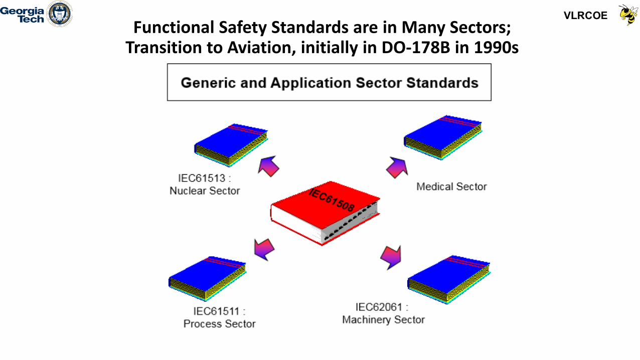
Functional Safety Standards are in Many Sectors; Transition to Aviation, initially in DO-178B in 1990s

Functional Safety Management: As Easy As (SIL) 1, 2, 3

Functional Safety Management interface with System Development Management (Fig 1, IEC 61508)

Eleven Steps in the Safety Lifecyle in IEC 61511

Functional Safety Management: As Easy As (SIL) 1, 2, 3
• Engineering companies and operations companies that apply functional safety have struggled to reconcile their long established work practices with the relatively new standards. At best compliance has been “partial”.
• The good news is that it really is not that difficult to comply. There is nothing particularly new or onerous. The principles are essentially the same as in quality management and risk management.
• The first step in achieving compliance is to prepare and to implement a “Functional Safety Management Plan”.

Development of Quality and Risk Management • In the 1980s industry experienced similar difficulties in understanding and
adopting quality management for lean manufacturing. The ideas behind managing quality are quite abstract and were embraced and articulated by the Japanese under the Total Quality Management (TQM) Umbrella with the need for implementing it through Concurrent Engineering for Just In Time and Lean Manufacturing. Similarly, the concepts of Six Sigma for risk management were introduced.
• Quality is primarily about understanding and satisfying a customer’s expectations. This includes implicit expectations, as well as explicit expectations. The techniques of specification, inspection and testing only make sense in a wider context which also addresses Risk and Uncertainty.
• Formal risk management was developed in the late 1980s and throughout the 1990s. Risk management principles are now widely understood and applied.
• Functional safety management simply applies quality management to systems that are designed to control risk through a Development Assurance (DA) process.

The 1980s Japan Wakeup Call for the Auto Industry: Total Quality Management through Lean Manufacturing and Six Sigma Processes

Japanese Auto Industry Made Changes Earlier Than U.S. Auto Industry (Basis of Need for Quality
Engineering)
90% Total Japanese
Changes Complete
U.S. Company
Japanese Company
20-2
4 M
onth
s
14-1
7
Mon
ths
1-3
M
onth
s
Job
#1
+3
Mon
ths
Num
ber o
f Eng
inee
ring
Prod
uct
Chan
ges
Proc
esse
d
Japanese/U.S. Engineering Change Comparison

Source: James Womack and Daniel T. Jones, Lean Thinking (New York: Simon & Schuster, 1996).
Lean Principles as Guiding Principles forModern Systems Engineering
• Establish and Specify value: Value is defined by customer in terms of specific products & services, preferably as a Benefits to Cost Ratio (BCR)
• Identify the value stream: Map out all end-to-end linked actions, processes and functions necessary for transforming inputs to outputs to identify and eliminate waste (Value Stream Map or VSM)
• Make value flow continuously: Having eliminated waste, make remaining value-creating steps “flow”
• Let customers pull value: Customer’s “pull” cascades all the way back to the lowest level supplier, enabling just-in-time production
• Pursue perfection: Pursue continuous process of improvement striving for perfection

15
Concept of Value
VALUE =FUNCTION
COST

Concurrent Engineering Now Required through Integrated Product/Process Design/Development (IPPD)

Internet/LAN/WAN•Wireless•Wired
PLM Environment
PDM
Maintenance Records•Schedules•Failure History•Maintenance History
Tools•Order Forecasting•Failure Forecasting•System Health Analysis
Inventory•Parts Lists•Order Info•Availability•Location•Order History
Operations Info•Interactive Forms•Tech Manuals•BOM•Schematics/Drawings•Procedures•Flight Data
Maintainer
Supplier
A Product Data Management(PDM) Focused PLM Environment Includes Aircraft Life-cycle Support

Product Lifecycle Management (PLM) Provides the IPPD Computer Integrated Environment
(Integration of CAD-CAE-PDM-CAM)

Industry and GT Recognized an IPPD Methodology is Required for Conducting Product-Process
Trades (NCAT Affordability WG, 1993)
SYSTEMPROCESS
RECOMPOSITION
SYSTEMFUNCTIONAL
DECOMPOSITION
COMPONENTFUNCTIONAL
DECOMPOSITION
COMPONENTPROCESS
RECOMPOSITION
PARTPROCESS
RECOMPOSITION
PARTFUNCTIONAL
DECOMPOSITION
ProductTrades
ProcessTrades
ProductTrades
ProcessTrades
PRELIMINARYDESIGN
(PARAMETER)
PRELIMINARYDESIGN
(PARAMETER)
DETAILDESIGN
(TOLERANCE)
DETAILDESIGN
(TOLERANCE)
MANUFACTURINGAnd Other Life Cycle
PROCESSES
CONCEPTUALDESIGN
(SYSTEM)
ProcessTrades
INTEGRATEDPRODUCTPROCESS
DEVELOPMENT
ProductTrades

Georgia Tech Developed Generic IPPD MethodologyCOMPUTER-INTEGRATED ENVIRONMENT
PRO
DU
CT D
ESIGN
DR
IVENPR
OC
ESS
DES
IGN
DR
IVEN
REQUIREMENTS & FUNCTIONAL
ANALYSIS
SYSTEM DECOMPOSITION &
FUNCTIONAL ALLOCATION
SYSTEM SYNTHESIS THROUGH MDO
SYSTEM ANALYSIS &
CONTROL
ESTABLISH THE NEED
DEFINE THE PROBLEM
ESTABLISH VALUE
GENERATE FEASIBLE ALTERNATIVES
EVALUATE ALTERNATIVE
7 M&P TOOLS AND QUALITY FUNCTION DEPLOYMENT (QFD)
ROBUST DESIGN ASSESSMENT & OPTIMIZATION
ON-LINE QUALITY ENGINEERING &
STATISTICAL PROCESS
MAKE DECISION
SYSTEMS ENGINEERING METHODS
QUALITY ENGINEERING METHODS
TOP-DOWN DESIGN DECISION SUPPORT PROCESS

IPPD Methodology Uses Simple Visual Set of Integrated Tools for First Iteration
Development of Quality and Risk Management
• In the early days of quality management the focus seemed to be on “Quality Control” or “Quality Assurance”. Emphasis was placed on inspection and testing. Quality was about conformance to specification. Non-Conformance Reports were seen as representative of quality control.
• Our understanding of quality management has evolved. Quality management principles are now better understood and include the use Robust Design Techniques, such as Taguchi’s Robust Design Simulation
• Quality begins with executive management taking overall responsibility, setting policies and implementing strategies.
• It requires taking a Development Assurance approach early in System Development vice a Quality Assurance approach later on, often too late

Development of Quality and Risk Management
• Quality management principles include: • Resource management (including competence, training and awareness) • Management of product realization • Measurement, analysis & improvement • Monitoring • Documentation
• Quality and Risk Management have evolved into the need for Concurrent Engineering (specifically Integrated Product & Process Development) and Development Assurance

Development of Quality and Risk Management
• The core of quality management is in “Product Realization”. It includes these main elements:
• Establishment & review of requirements • Design and development
• inputs • outputs • review • verification • validation
• Change control • Purchasing
• These same elements form the core of functional safety management. • Functional safety management can be seen as a specific application of quality
management

Development of Quality and Risk Management • Functional safety management follows the same classic systems
engineering “V-model” which is central to quality management:

Systems Engineering Vee Diagram for Road Vehicles Functional Safety Guidance Standard

Development of Quality and Risk Management • Risk Management for Safety Assessment
• In the 1980s it was not easy to answer the question of “what should we do to improve safety?” • It was an admirable goal but it seemed like such a vague question. It was difficult to formulate
objective and specific activities without resorting to ‘motherhood statements’ such as “safety is our number 1 priority”.
• In the 1990s the adoption of ideas like “Safety SAM” made the message easy to understand: • Spot the hazard • Assess the risk • Manage the hazard
• Australia and New Zealand together published the world’s first risk management standard (AS/NZS 4360: 1995, revised in 1999 and now superseded in 2009 by AS/NZS ISO 31000).
• Risk management principles are now well understood worldwide: • Establish context • Identify • Analyze • Evaluate • Treat

AS/NZS ISO 31000 Figure 1 Relationships between the risk management principles, framework and process

Basic Risk Management Chart

SE Decision Mod 10 - 30
What is Risk Analysis?• What is the Probability of Failure for Each Option Given
the Investment?• What functionalities are needed?
• How can they be fulfilled?• What is the probability of failure of the whole system as a
function of the p(Fi) of each subsystem i?• What are the costs of each option?• How much reliability will be gained by investing in each
subsystem?• How much overall reliability will be gained for each well-
allocated increment of resources?
• Risk Analysis is used to determine Risk Mitigation approaches and the Level of Confidence in Achieving them.

Mitigating Risks• If a safety risk is intolerable you can take one or more of the following mitigation
actions:• Add safety functions to the system• Employ other technologies• Change the environment to make it inherently safer• Introduce manual safety procedures.
• If you introduce a protection system to reduce risk you are now "trusting" it to do its job. Safety integrity is a measure of that trust.
• Say for example, that to deliver an acceptably safe passage through an intersection, the dangerous failure rate of your traffic signaling controller cannot exceed 1 in 10,000 years (Λp). But what if your estimated failure rate for the current controller is 1 in 10 years (Λnp)? Clearly your conflict monitor must contribute the additional safety margin. Its required reliability can therefore be quantified as Average Probability of Failure on Demand (PFDavg) = Λp/Λnp = 1 in 1,000 or, in plain English, for every 1,000 dangerous failures of the controller the conflict monitor must work, as specified, 999 times.

IEC 61508 Safety Integrity Levels• IEC 61508 classifies safety integrity in terms of 4 bands labeled 1 to 4
where 4 is the highest. Safety-related systems can then be characterized by a Safety Integrity Level (SIL). For example, railway authorities classify railway signaling as a SIL 4 application while road transportation authorities have classified variable message signs as SIL 1. In an example of an intersection conflict monitor, with a required PFDavg of 1 in 1,000, would be classified as SIL 2 (refer to the Table).

Assessing Residual Risks
• Taking into account the risk reduction measures already in place, a risk assessment team determines if the safety risk has been reduced to a level that is As Low As is Reasonably Practicable (ALARP).
• You have reached ALARP when further risk reduction is impracticable or its cost is grossly disproportionate to the improvement gained.
• If the risk is intolerable further risk reduction measures are introduced.
• For example, in road transportation risk might be further reduced by modifying the geometry of an intersection to improve driver visibility.
• If all else fails you may choose to refuse the risk and not engage in the risky activity at all.

Specifying Safety Requirements• Testable safety requirements are the most important outputs of a
hazard analysis. A safety requirement describes the behavior of a safety function and specifies its required reliability in a way that can be verified as the system is developed and validated before it is set to work
• The functional safety standards must deal with managing the risk of both random failures and systematic failures
• Random Failures – fairly mature for system reliability; however to a lesser extent for mission or phase based reliability; relationship between reliability, availability, maintainability and safety (surety) not well understood for integration at the complex system level
• Systematic Failures – include hardware, liveware and software errors that must be addressed in designing and developing the complex system and its subsystems, starting with functional hazard assessment

Specifying Hardware, Liveware and Software Reliability
• Hardware reliability is commonly specified as a failure rate (e.g. failures per hour). Hardware systems can be built to this specification as manufacturers provide failure rate estimates for components such as integrated circuits, switches and indicators.
• In contrast liveware and software reliability cannot be specified as all software failures originate from human error which is notoriously unpredictable. This failure mode is referred to as "systematic failure", for example, failure to follow proper practice in system development and operation resulting in incorrect system requirements, design errors and coding errors in software programs. Systematic faults also extend to inadequate design review, incomplete testing and lack of competence in managers, developers and operators

Functional Safety – Using Quality to Manage Risk
• Functional safety refers to “Safety Instrumented Systems” that implement “Safety Instrumented Functions” (SIFs) as part of a company’s overall risk management strategy.
• A Safety Instrumented Function is designed to respond to a specific hazardous event. It implements an action that will achieve or maintain a safe state for the equipment under control.
• Functional safety must always be seen within the wider context of company risk management. It cannot be seen in isolation, it makes no sense without that broader basis.
• Functional safety is just one element in a range of risk treatments. A company’s risk managers may use Safety Instrumented Functions together with a number of other risk reduction measures to control risk exposure.

Functional Safety – Using Quality to Manage Risk
• The target level of risk reduction for each SIF is determined to ensure that the overall risk to personnel is as low as reasonably practicable.
• Each SIF is defined with a Safety Integrity Level (1,2 or 3) according to the Risk Reduction Level that is required from that function (10-1, 10-2, 10-3).
• A Safety Instrumented System is composed of a combination of • Sensors • A logic solver • Final elements such as actuators and valves
• The functional safety standards provide a very specific quality management system to implement one part of an overall risk management strategy.

Functional Safety – Using Quality to Manage Risk: Systematic Integrity
• The functional safety standards deal with managing both random and systematic failures.
• Management of the risks associated with random failures has been relatively easy to understand. Random failures can be characterized by failure rate and/or Mean Time Between Failures (MTBF).
• Safety instrumentation is characterized by its “Probability of Failure on Demand” (PFD) and “Safety Integrity Level” (SIL).
• The mathematics underlying failure rates, MTBF, PFD and SIL are well defined.• It is a simple process to characterise and quantify risks through estimating their
likelihood and consequence. • Each Safety Instrumented Function is designed to deliver a specific Risk
Reduction Factor, and that gives it a target Probability of Failure on Demand • The biggest challenge here perhaps is that we need to be comfortable in dealing
with uncertainty and ambiguity.

Functional Safety – Using Quality to Manage Risk: Systematic Integrity
• It has been significantly more difficult to embrace the management of systematic failures. This is primarily to do with how we manage our engineering methods and techniques. It deals with avoiding errors and failures due to the design and implementation of the systems.
• It is just as important to achieve systematic integrity as to achieve the safety integrity levels that we quantify through probabilities of failure.
• The good news is that it really is not that difficult to comply. There is nothing particularly new or onerous. The principles are essentially the same as in quality management and risk management.

Functional Safety Management Planning
• There is no law that specifically requires us to comply with IEC 61508 or IEC 61511.
• However it is very clear that these are the appropriate standards for managing functional safety in the process industries.
• A company that chooses to use Safety Instrumented Functions in managing risk needs to demonstrate that it has taken reasonable steps to comply with these standards.
• There should be a deliberate process to plan how the standards will be applied. Without a plan compliance will be ad-hoc and difficult to demonstrate.
• In exactly the same way that a company will have a Quality Plan, an OHSE Plan or a Risk Management Plan it should also have a Functional Safety Management Plan.

Functional Safety Management Planning
• The need for Functional Safety Management Planning (FSMP) applies to all of the parties involved in engineering and operating a functional safety system:
• Owners • Engineers • Suppliers • Operators • Maintainers
• Functional Safety Management Planning helps us to ensure that we achieve the required systematic integrity as well as achieving the required safety integrity.

What is a Safety-related System?
• A system is "safety-related" if its failure can cause harm to life and property. Examples are: chemical processing control systems, aircraft avionics systems, road and railway signaling systems and office building smoke extraction systems

Why is Functional Safety Necessary?
• The consequences of system failure have become more serious as we increasingly trust software and electronic systems to protect us from harm. At the same time these systems have become infinitely more complex with the introduction of computer software and electronic hardware.
• Software can be both a benefit and a hazard. It is highly adaptable to any situation but can be hazardous because:
• Its inherent complexity makes software development an error prone activity• Its invisibility makes producing zero defect code impossible and• Its lack of testability makes it difficult to find and fix all defects that might
cause dangerous failures.

Part 2: Evolution of Functional Safety Management for Civil Aircraft and
Systems to its Current Global Application
Dr. Daniel P. SchrageProfessor and Director, Vertical Lift
Research Center of Excellence (VLRCOE)School of AE, Georgia Tech

Presentation Outline
• Aviation Functional Safety Management History starting with DO-178A/B and ARP 4754 & ARP 4761 in 1990s and future expansion
• Development of ARP 4754A and its role as the civil aircraft level guide, along with plans for follow-on updates, such as from ARP 4761 to ARP 4761A
• Planned Development of follow-on versions, such as DO-257 for Cyber Physical Systems and fully Integrated Modular Avionics (IMA) Systems
• Why Military Aircraft Development does not include effective early coupling with Functional Safety Assessment
• Impact of tailoring Functional Safety Management standards for Uninhabited Aerial Systems (UAS) which makes the most sense
• Introduction of tailored approach for small and large UAS, e.g. sUAS and LUAS as a departure from manned aircraft airworthiness and certification standards

Civil Aviation Functional Safety Management History• Started in the early 1990s with the development of DO-178A/B for Software Development for Aviation
Systems; closely followed by the development of SAE ARP 4754 and ARP 4761 in the mid 1990s.• The Concept of Development Assurance Levels (DALs) was introduced; somewhat as a parallel to the
Safety Integrity Levels (SILs), as identified in IEC 61508 and IEC 61511. Both DO-178A/B and ARP 4754 use DALs, although with slight differences in definition and application.
• The tight coupling of Civil Aircraft and Systems Development, AR4754, with ARP 4761, Safety Analysis Assessment Methods has proven to be very beneficial for assessing Development Assurance with Safety Analysis and Risk Management. A contiguous example, S-18 Aircraft, in ARP 4761, is beneficial.
• Later, a new Document Order (DO) 254 for Electronic Hardware Development for Aviation Systems was developed and introduced.
• In the 2000s Boeing and Airbus moved from federated to integrated, distributed avionics architectures for new civil aircraft, such as the Boeing 777/787 and Airbus 380/350, which has required the introduction of DO 297 for Integrated Modular Avionics (IMA) for Civil Aircraft
• In 2010 the U.S. and Europe issued a new ARP 4754A/ ED 79, which brought together a common description of the DAL from the Aircraft Level, down to IMA and Item levels, e.g. Electronic Hardware and Software.
• However, with the continued acceleration of integrated software solutions for even more complex civil aircraft, there is work underway to update ARP 4754A and ARP 4761 to include a contiguous example between them and perhaps the DOs; also there is work underway by the civil avionics/FBW/FBL community to include an update or new DO 297 to include the need to address reconfiguration and shared functionality on multi-core processes.

Aviation Functional Safety Management Guidance• Aviation is among the safest industries in the world and it applies Functional
safety in many areas, including for example the automated flight control system.
• The two-axis autopilot system controls the pitch and roll of the aircraft and controls heading and altitude, all of which are programmed to respect certain Functional safety parameters, activating alarms and other measures when they are breached
• Initial aviation functional safety management was documented in DO 178B, “Software Considerations in Airborne Systems and Equipment Certification”
• Initial aviation function safety management approach expanded to a set of interrelated DOs and ARPs accepted in US and Europe through consensus
• With the movement to full authority Fly By Wire (FBW) in modern civil and military aircraft avionics and flight controls are now being fully integrated into adaptive Air Vehicle Management (AVM) systems.

Boeing View of Trends in Systems Architecture(John Dalton, AEROTECH 2012)


Past Civil Aviation Functional Safety Certification Integrated Guidelines

SAE ARP 4761: Guidelines and Methods of Performing the Safety Assessment Process on Civil
Airborne Systems and Equipment

Functional Hazard Assessment

Mission Profiles Define Functions for System Effectiveness Criteria

Functional Hazard Assessment
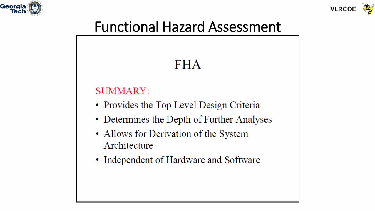
Functional Hazard Assessment

Example Aviation Target Level of Safety (TLS) and Risk Budgeting: “Equipment failures in ATC - Finding an appropriate safety target”

The 2010 Issuance of ARP 4754A/ED-79 provideda Global Functional Safety Standard, included component hardware, software
and IMA for Aircraft Synthesis

8/25/2016 59
Commercial Manned Aircraft System Process Development Model Interactions with Safety Assessment Processes per
ARP 4754A & ARP 4761
AircraftLevel
Require-ments
Allocation of Aircraft
Functions to Systems
Developmentof System
Architecture
Allocation of Requirements to Hardware &
Software
System Implement-ation
Safety Assessment Process (ARP 4761) Cer
tific
atio
n
Aircraft Functions
System Development Process (ARP 4754A)
Fail Conditions, Effects, Classification, Safety Objectives
System Functions
Fail Conditions, Effects, Classification, Safety Objectives, Architecture Requirements
Item Require-ments
Final Implement-ation

Generic Development Program for Civil Aviation, ARP 4754A

Civil Aviation has Moved from a QA to DA Approach(SAE ARP 4754A, 2010)
DEVELOPMENT
ASSURANCE(DA)
QUALIFICATION
ASSURANCE(QA)

Civil Aviation Development and Safety Assessment is based on establishing Development Assurance Levels for both the
Aircraft and Systems/Items/components

63
Preliminary Aircraft Safety Analysis (PASA) and Preliminary System Safety Analysis (PSSA) are conducted to determine Functional Development Assurance Level
(FDAL) and Item Development Assurance Level (IDAL) Assignment,e.g. FBW System
Brett Walter

Difficulties with Applying Integrated Civil Aircraft and Systems Development with Safety Assessment Process for other Aviation
Systems, e.g. General Aviation, Military and UAS
• The Civil Aircraft Integrated Approach is driven by large Commercial Transport Manned Aircraft (led by Boeing and Airbus) who set the aviation standards which then sets the safety bar for other aviation systems
• Difficult, if not impossible, for General Aviation and Civil Rotorcraft to comply with the same Failsafe and DAL levels, either economically or due to single point failures
• Difficult for Military Aircraft to apply early integrated development and safety assessment as funds are often unavailable until after Milestone B; Also, need a military aircraft level standard, like ARP4754A, for implementation
• Unmanned Aerial Systems (UAS), both small and large, have broader Concepts of Operations (ConOps) which must be functionally defined, some which may be simpler and some which may be more complicated than manned aircraft systems

Traditionally a Program Management Office (PMO) isn’t established until MS A and AQP established for MS B

For Army Military Aircraft, the ADS-51 Rotorcraft and Fixed Wing Airworthiness Qualification HDBK is Mostly used for
Qualification Assurance, Not Development Assurance
Fabricate, Assemble,Code to “Build-to”
Documentation
Integrated DT&E, LFT&E & EOAs Verify Performance
Compliance to Specs
Individual CIVerification
DT&E
VerificationLinkage
VerificationLinkage
VerificationLinkage
Evolve CI FunctionalSpecs into Product
(Build to) Documentation& Verification Plan
System DT&E, OT&E, LFT&E& OAs Verify System
Functionality & ConstraintsCompliance to Specs
Develop System FunctionalSpecs & Verification Plan to
Evolve System FunctionalBaseline
Evolve FunctionalPerformance Specs into
System Allocated Baseline
Hardware/Software Integration LabsCertified lab, models, H/W, etc
Platform Integration Test
Qualification TestingEnvironmental (MIL-STD-810)Electromagnetic Environmental Effects(ADS-37A-PRF, MIL-STD-461)
Performance/Reliability TestingSoftware Development (RTCA DO-178B)

“There is a need to develop an industry standard method for qualifying complex integrated systems to a specified reliability. The goal of this paper is not to resolve the problems or evaluate past or existing designs, but it is to catch the attention of government and commercial aviation industry and solicit input into new processes and standards to correct the longstanding issues in the development of complex avionics systems.”
The Need for a New Military Aircraft StandardHas been clearly Identified
(Boydston, A., and Lewis, W., Qualification and Reliability of ComplexElectric Rotorcraft Systems, AHS Spec Mtg on SE, Oct. 2009)

Proposed Standard Modeling Methodology for New Proposed Standard (Boydston, A, Lewis, W.)

• Georgia Tech and UAH, along with industry partners, Dassault Systems and Clausewitz Technology, have recently developed a draft Aeronautical Design Standard (ADS) on “Guidelines for Military Aircraft Development through Development Assurance Value Based Acquisition (DAVBA)”.
• This draft ADS has been designated ADS-X1 and starts with addressing how the military airworthiness qualification process can utilize the development assurance process defined in ARP 4754A to establish and tightly couple the airworthiness process in conjunction with the program design of military acquisition programs.
• The proposed Integration of Development Assurance (DA) with Value Based Acquisition (VBA) is a step further for closely coupling the Development Process with Functional Safety assessment
DEVELOPMENT OF A HYBRID CIVIL-MILITARY AIRCRAFT DEVELOPMENT ASSURANCE AND SAFETY
ASSESSMENT STANDARD, ADS-X1 FOR FVL/FTUS

• The ADS-X1 provides a contiguous example, based on a UH-60M Baseline, on how this process can be integrated into a top level stochastic model of the weapon system effectiveness, based on a ratio of System Effectiveness to Life Cycle Cost.
• The use of a Development Assurance Value Based Acquisition (DAVBA) metric to evaluate the safety assessment process in conjunction with the system performance and cost metrics also provides tradeoff environment for a Business Case Analysis (BCA).
• The pseudo connection of DA to a Functional Development Assurance Level (FDAL) is through the Availability and Dependability criteria models, where both managing the risk of both random failures and systematic failures are addressed, e.g. random failures through System Reliability and systematic failures through FDAL
DEVELOPMENT OF A HYBRID CIVIL-MILITARY AIRCRAFT DEVELOPMENT ASSURANCE AND SAFETY ASSESSSMENT STANDARD, ADS-X1 FOR FVL/FTUS

Transfer from Deterministic Virtual Prototyping to Stochastic Virtual Prototyping

Proposed Notional Vee Diagram Layout for FVL DAVBA Approach

A Value Based Acquisition (VBA) Model Based Engineering (MBE) Approach is Utilized with the
Development Assurance (DA) Process

Obtaining a Balanced FVL Solution througha Value Based Acquisition (VBA) Metric Trade Studies

Well known that Life Cycle Cost for Complex Systems get Locked in Early

The DAVBA Approach can Address the Risk and Uncertainties of FVL through Trade Studies for a
Balanced Solution

A Successful FVL Balanced Solution will require Unprecedented VL Community Collaboration