understanding and optimizing bgp peering relationships ... · understanding and optimizing bgp...
TRANSCRIPT

WHITE PAPER
Understanding and Optimizing BGP Peering Relationships with Advanced Route and Traffic Analytics

Copyright © 2014, Packet DesignPage 2 of 14
Table of Contents
Introduction 3
Route-Flow Fusion 4
BGP Policy Visibility 5
Traffic Visibility 7
Traffic Modeling 10
Other Benefits of Route-Flow Fusion 12
Conclusion 13

Understanding and Optimizing BGP Peering Relationships
Copyright © 2014, Packet DesignPage 3 of 14
IntroductionThe Border Gateway Protocol (BGP) connects autonomous systems (AS) to each other. Using BGP, a border router in one AS peers with a border router in another AS and then these routers exchange routes that are known to them. If a router advertises a route to a peer, the peer router can then send packets for this route’s destination to it. The packets transit the next AS until they are either passed to another AS or delivered to their destination (when the destination is local). By announcing a route, an AS allows another AS to use its resources for transiting packets. Policy constraints determine what routes are announced and implement the business relationships between the ASs.
Two common policy constraints (hence business relationships) between ASs are provider-customer and peer-peer. In provider-customer relationships, which are typically used between enterprises and service providers or between regional service providers and global service providers, the customer AS pays the provider AS for transiting packets to their destinations (and back). The cost is usually proportional to the volume of traffic transited. In this case, the provider announces all its known routes to its customers. In peer-peer relationships, there is no compensation and each AS announces only its own routes (including customer routes) to the other AS. In this case, an AS can only use the next AS’s resources for transiting traffic destined for that AS’s internal or customer destinations. That is, the next AS does not transit packets to third party destinations.
Large service providers with global reach, referred to in this white paper as top-tier service providers, typically use the peer-peer policy with each other. If an arbitrary service provider could peer with them with this policy, it would save significant transit cost. But before peering, top-tier ASs typically require the same geographical reach they have, the ability and willingness to peer at several geographically dispersed locations, somewhat symmetric traffic volumes exchanged in each direction, and many other operational constraints. As a result, most ASs, including regional service providers, end up paying for transit. Similarly, most enterprises buy transit from either regional service providers or top-tier service providers.
However, there is room for peer-peer policy even for the smallest service providers. They can peer with other small service providers in their region or with content providers (who would also be cutting costs and providing a better experience to their users). This is only worthwhile if there is significant traffic exchanged between the two ASs. The transit savings need to justify the cost of the direct link between the two ASs (and other infrastructure such as optical ports and cross connects). Internet Exchange Points1 make peering between ASs more economical.
Peering decisions among the top-tier service providers are also not straightforward. For example, Acme USA, a fictitious top-tier service provider with a very robust network in North America, might receive a peering request for the Chicago area from another top-tier service provider with a smaller presence in the North American market. If Acme was to accept this request without understanding the ramifications, it could find itself at a competitive disadvantage. At a minimum, Acme should assess whether the Chicago traffic would be symmetric in both directions. If the peer passed more traffic, it would not be advantageous, because (1) Acme would be transiting more of the traffic, and (2) the other service provider
1 An Internet Exchange Point provides a co-location facility where many ASs host routers, and using the local area network of the facility, ASs establish BGP peerings and exchange traffic with each other.

Understanding and Optimizing BGP Peering Relationships
Copyright © 2014, Packet DesignPage 4 of 14
would improve its user experience because its customers would see shorter end-to-end delays when communicating with other North American destinations.
Making informed peering decisions impacts the bottom line of all service providers whether they are top-tier, regional, or even smaller. So how can they make informed peering decisions? First and foremost, a service provider needs to have traffic visibility: (1) how much traffic it is sending to and receiving from its providers, peers and customers (i.e. neighbor ASs), (2) where this traffic is going to or coming from (source and destination ASs), and (3) what other ASs this traffic transits along the way (transit ASs).
With this type of traffic visibility, a service provider can optimize BGP peerings to reduce AS transit costs. For example, an educational network in one of the United States noticed a significant portion of its traffic going to a local cable Internet provider. This was not surprising given that the students and faculty accessed school resources while they were at home. The educational network was able to peer with the cable Internet provider directly and both parties were able to reduce transit costs.
Secondly, to make informed decisions, a service provider needs to be able to model the impact of peering changes. For example, when running out of transit capacity, the service provider must decide whether it should (1) upgrade the capacity of the existing links, (2) add a new link at another location to the same provider, or (3) peer with a completely new provider. A planning tool can help answer these questions. To model these changes accurately, the tool must analyze and model both BGP routes and policies as well as Interior Gateway Protocol (IGP) routes and the service provider’s network topology.
Historically, network engineers have lacked comprehensive information and tools for managing Internet peerings. Incomplete routing and traffic data, siloed analyses, and static modeling tools have handicapped their efforts. However, recent innovations in routing and traffic analytics provide a much more holistic view of peering relationships, and the ability to model peering changes and predict their outcomes accurately.
Route-Flow FusionTraffic analysis tools work by analyzing flow records exported by routers using IPFIX, NetFlow, J-Flow, NetStream and other similar technologies. These are per-interface records and typically contain MPLS labels, IP source and destination addresses, IP class of service and protocol, and transport level port numbers along with start time and duration of the flow and number of bytes transmitted. Some variations may also contain limited source and destination AS numbers. Most flow analysis tools, can sum the traffic volume of these flows for each source and destination IP address, port, and AS number and generate top-N reports for each interface where flow records are exported.
What conventional traffic analysis tools lack, however, is the ability to determine the exact path, from source to destination, of each flow across the network. Therefore, critical insight into traffic behavior and performance is missing. However, an innovative, patented technique called Route-Flow Fusion reveals the path for each flow in an accurate and economic fashion. By combining route analytics and traffic analytics,

Understanding and Optimizing BGP Peering Relationships
Copyright © 2014, Packet DesignPage 5 of 14
for each flow record received, the complete path—both forward towards the destination and backward towards the source of the flow—can be computed. This path includes links and routers in the network as well as external links, upstream and downstream neighbor ASs, transit ASs, and destination and source ASs.
Route-Flow Fusion has several benefits. First, it provides much richer traffic visibility. The second benefit is visibility into traffic even for links where flow records are not exported. For example, a regional service provider that handles mostly Internet traffic could monitor just its external links and Route-Flow Fusion technology would calculate and map traffic flows across the internal links. The third benefit is easier detection of duplicate flows so that the same flow exported at multiple links is counted only once in each report (often referred to as flow de-duplication).
BGP Policy VisibilityAs noted above, BGP policies directly impact the volume of peering traffic. Route analytics will show whether current router configurations implement the BGP policies correctly. The dynamic set of BGP routes are analyzed and the results may be viewed by peer and next-hop routers, neighbor, transit and origin (destination) ASs, local-pref and MED values (not discussed here) as well as BGP communities. Figure 1 shows the number of routes announced by each neighbor AS plus the number of routes originated by each origin AS.
Figure 1: BGP Routes by Neighbor and Origin ASs.
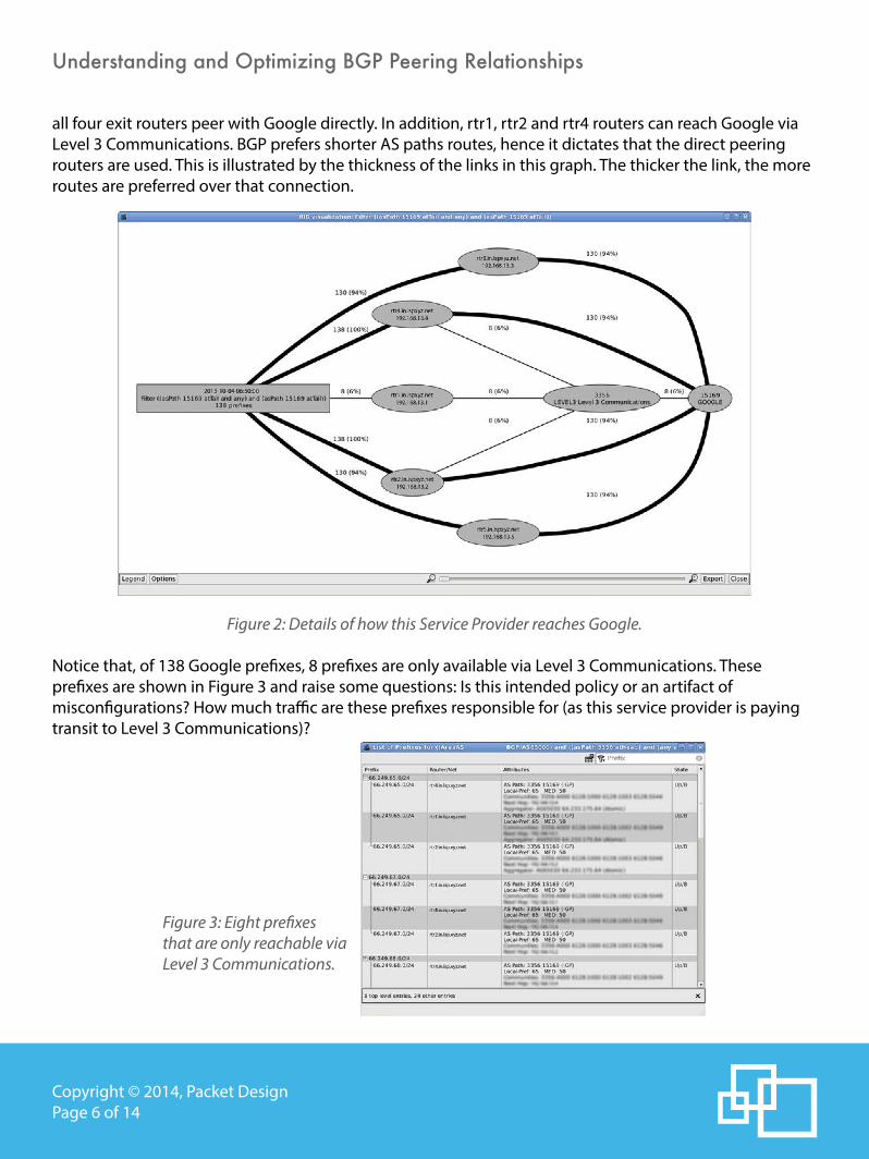
From one of these entries, it is possible to visualize or list that set of routes. Figure 2 visualizes routes originated by Google’s AS 15169, that is, it reveals the details of how this service provider reaches Google. As can be seen in the figure, there are 5 exit routers labeled rtr1 through rtr5. With the exception of rtr1,
Understanding and Optimizing BGP Peering Relationships
Copyright © 2014, Packet DesignPage 6 of 14
all four exit routers peer with Google directly. In addition, rtr1, rtr2 and rtr4 routers can reach Google via Level 3 Communications. BGP prefers shorter AS paths routes, hence it dictates that the direct peering routers are used. This is illustrated by the thickness of the links in this graph. The thicker the link, the more routes are preferred over that connection.
Figure 2: Details of how this Service Provider reaches Google.
Notice that, of 138 Google prefixes, 8 prefixes are only available via Level 3 Communications. These prefixes are shown in Figure 3 and raise some questions: Is this intended policy or an artifact of misconfigurations? How much traffic are these prefixes responsible for (as this service provider is paying transit to Level 3 Communications)?
Figure 3: Eight prefixes that are only reachable via Level 3 Communications.

Understanding and Optimizing BGP Peering Relationships
Copyright © 2014, Packet DesignPage 7 of 14
Traffic VisibilityFigure 4 shows a regional service provider’s network-wide traffic over the course of a week. Typical diurnal variation can be seen with the traffic peaking at approximately the same time around noon every day and much more modest traffic levels during the weekend.
Figure 4: Total Network-Wide Traffic.
Source and destination AS traffic reports identify where the traffic is coming from and going to, respectively, and are illustrated in Figure 5. While there are many customizable statistics available, shown here are the 5-minute average, and daily, weekly and monthly 95th percentile traffic volumes. For the top-6 source ASs, Figure 6 shows the traffic variation over the same week.
Figure 5: Source and Destination AS Traffic.

Understanding and Optimizing BGP Peering Relationships
Copyright © 2014, Packet DesignPage 8 of 14
Figure 6: Weekly Traffic to Top-6 Source ASs.
For this network, the top source AS is Google. Is direct peering with Google a possibility? This service provider indeed peers with Google and reduces transit cost for 13Gbps Google traffic. The source AS traffic report is not limited to top-N ASs. Though peering with the top few ASs would cut the transit cost the most, it may not always be feasible due to geographic distance. Peering with ASs lower in the ranking may be more practical. Or perhaps there is another AS that can provide transit (either paid, or free if there is mutual benefit) to many of these source ASs. Upstream and downstream transit AS traffic reports present these opportunities and are illustrated in Figure 7.
Figure 7: Upstream and Downstream Transit AS Traffic.

Understanding and Optimizing BGP Peering Relationships
Copyright © 2014, Packet DesignPage 9 of 14
For a regional service provider where the majority of the traffic is coming from the Internet, the upstream transit AS traffic report is most applicable for making peering decisions. Note that, even though Route-Flow Fusion determines the source AS of the flows deterministically, the path that this traffic takes is up to the policies of the source AS and the transit ASs along the way. This is not distributed directly in BGP and hence it cannot be determined by Route Analytics in the usual way. To get around this limitation, a patented heuristics-based algorithm was devised to take advantage of the combinatorial AS path exploration that happens during BGP convergence, and create a policy-aware graph of the ASs in the Internet. From this, it is possible to know the transit ASs that may pass each source AS’s traffic if peered directly.
The combination of Route and Traffic Analytics will also reveal upstream and downstream neighbor ASs (i.e. direct peers), broken down into individual external links and BGP communities. Source and destination IP address-based traffic groups can be defined to further increase the granularity of this information. These reports are valuable for determining when to upgrade the capacity of the peering links.
Even when the flow records are exported only by the BGP peering links, Route-Flow Fusion can project these flows across internal links in the network. This is illustrated for a single flow in Figure 8. After projecting all the flows, the resulting link utilizations for all the internal links are shown in Figure 9 by color-coding the links by their utilization levels on the topology map.
Figure 8: Projection of a Flow to its Path.

Understanding and Optimizing BGP Peering Relationships
Copyright © 2014, Packet DesignPage 10 of 14
Figure 9: Traffic Levels on the Internal Links.
Traffic ModelingWhen making peering decisions, a planning tool is needed to model routing changes, such as adding a BGP peering. Route-Flow Fusion makes this type of planning extremely easy because the underlying model includes the path of the flows. When paths are changed during the modeling exercise, Route-Flow Fusion technology can compute the before and after comparative traffic volumes on the internal and external links and ASs.
This method of modeling is virtually instantaneous unlike conventional planning tools that require hours or days to build an accurate network model. With Route-Flow Fusion, the model is based on IGP and BGP routing events, and is, therefore, always accurate and available in real time. As well as adding and failing links, prefixes and routers, Route-Flow Fusion technology makes it possible to model the adding and downing of BGP peerings. The dialog box in Figure 10 illustrates an example of this. When adding a BGP peer, it is possible to auto-select the routes that would be announced by this new peer, such as all the routes that have the peer’s AS number in the BGP AS-path attribute. The policies can then be further fine-tuned as illustrated in Figure 11.

Understanding and Optimizing BGP Peering Relationships
Copyright © 2014, Packet DesignPage 11 of 14
Figure 10: Adding a new BGP Peer.
Figure 11: Fine-tuning BGP Policies by changing the Local-Pref BGP Attribute Values.
Afterwards, for each traffic report, a before and after comparative view is presented. For example, after modeling the changes in Figure 10 (using a small laboratory topology), the destination AS report can be seen in Figure 12. Though the traffic volumes did not change, all the traffic was rerouted to the new peering location as shown in the last column of the report.

Understanding and Optimizing BGP Peering Relationships
Copyright © 2014, Packet DesignPage 12 of 14
Figure 12: Before and After Destination AS Traffic Volumes.
Other Benefits of Route-Flow FusionUse cases are not limited to BGP peering traffic analysis. Route-Flow Fusion technology understands layer 3 BGP/MPLS IP VPNs as well as Martini-style pseudo-wire-based layer 2 VPNs. For each VPN service or customer, it provides visibility into where traffic enters the network, what paths it takes, and where it exits the network. This information can be used to generate traffic matrices. A sample traffic matrix, combining Internet, layer 2 and layer 3 VPN traffic, is shown in Figure 13.
Figure 13: Internet, Layer 2 and Layer 3 VPN Combined Traffic Matrix.

Understanding and Optimizing BGP Peering Relationships
Copyright © 2014, Packet DesignPage 13 of 14
RSVP-TE tunnels may also be monitored, along with their paths and how much traffic they carry. It is possible to perform failure analysis and determine whether fast re-route or secondary paths have sufficient capacity to handle extra traffic volume during a failure. Tunnel reports show daily, weekly and monthly minimum, average, maximum, and 95th percentile traffic volumes. This data can be used in router configurations for more accurate tunnel bandwidth reservations.
For multicast routing, all Protocol Independent Multicast (PIM) trees in the network can be monitored. It is also possible to project multicast traffic across network links to understand its behavior. Applications like IPTV introduce significant multicast traffic load in the network, and performing traffic engineering while ignoring this load is no longer realistic and appropriate.
Route-Flow Fusion technology captures and stores all routing events and calculated traffic paths in a high-performance database. This enables a DVR-like capability to replay routing and traffic events for diagnosing root causes of problems. For example, network time can be “rewound” to a point in time when a link was congested so that the traffic on the link can be analyzed. It is possible to see where that traffic was coming from, where it was going, what path it took, and most importantly, what policy should be put in place to avoid similar congestion in the future.
ConclusionRoute-Flow Fusion technology helps network operators reduce transit costs and provide higher service quality by providing visibility into inter-AS traffic. Real-time operational monitoring and back-in-time forensic analysis help NOCs manage service delivery proactively, and modeling capabilities enable engineers to predict accurately how proposed peering changes will affect traffic, thereby decreasing the chances of design errors or misconfigurations.
Packet Design invented route analytics and the patented Route-Flow Fusion technology that integrates flow data to provide path-aware traffic analytics. The Route Explorer™ System is used by the world’s largest telecommunications companies, mobile operators, MSOs, service providers, enterprises and government agencies to ensure quality and continuity of services, reduce problem MTTR, and contain infrastructure costs by making more informed investment decisions.

Understanding and Optimizing BGP Peering Relationships
Copyright © 2014, Packet DesignPage 14 of 14
To learn more about Packet Design and Route Explorer, please:• Email us at [email protected]• Visit Packet Design’s web site at www.packetdesign.com• Call us at +1.408.490.1000
Corporate HeadquartersPacket Design2455 Augustine DriveSanta Clara, CA 95054 Phone: 408.490.1000Fax: 408.562.0080