understanding 5g new radio release 15/16 standards · paging channels ue monitors paging channels...
TRANSCRIPT

1
Keysight Technologies DEC 2019
U N D E R S TA N D I N G 5 G N E W R A D I O R E L E A S E 1 5 / 1 6 S TA N D A R D S

22
• Technology Overview & Timeline
• Carrier Aggregation & Bandwidth Adaptation
• Numerology & Frame Structure
• Waveforms & Modulations
• Beams, Beamforming & Beam Management
• Initial Access Procedure, Example Call Flows
• Network Architecture, Deployment Options
• New Features Coming in Rel-16
A G E N D A

33
B R O A D R A N G E O F N E W S E R V I C E S A N D PA R A D I G M S
URLLCeMBB
Mobile Broadband Access
Massive Machine Communication
Mission-CriticalMachine Communication
IoT
• All data, all the time
• 2 billion people on
social media
• 30 billion ‘things’ connected
• Low cost, low energy
• Ultra-high reliability
• Ultra-low latency
mMTC
Amazingly FastGreat Service in a
Crowd
Best Experience
Follows You
Ubiquitous Things
Communicating
Real-time & Reliable
Communications

44
Source for Spider Diagram: ITU: 5D/TEMP/390-E
4G
5G
3G

55
A L I G N E D W I T H I M T V I S I O N
• IMT 2020 are still defining specs
• IMT: International Mobile Telecommunications Initiative (by ITU)
Rel-15
5G Phase 1
Rel-16
5G Phase 2
2018 2020
Rel-13Rel-12
LTE-A
2015
Rel-14
2016 2017
Phase 2 – mid 2020
• Focus on new verticals (IIoT, V2X, etc.)
• Novel layers and architecture to allow full 5G
potential (vehicular and multicast services)
• “mmWave” 28, 37, 39 GHz channels and
unlicensed spectrum
Phase 1 – mid 2018
• Focus on eMBB and low latency aspects
• Minimized changes to core architecture (LTE-
EPC) – NSA operation initially
• 5G RAT - focus on “conventional” frequency
channels
66
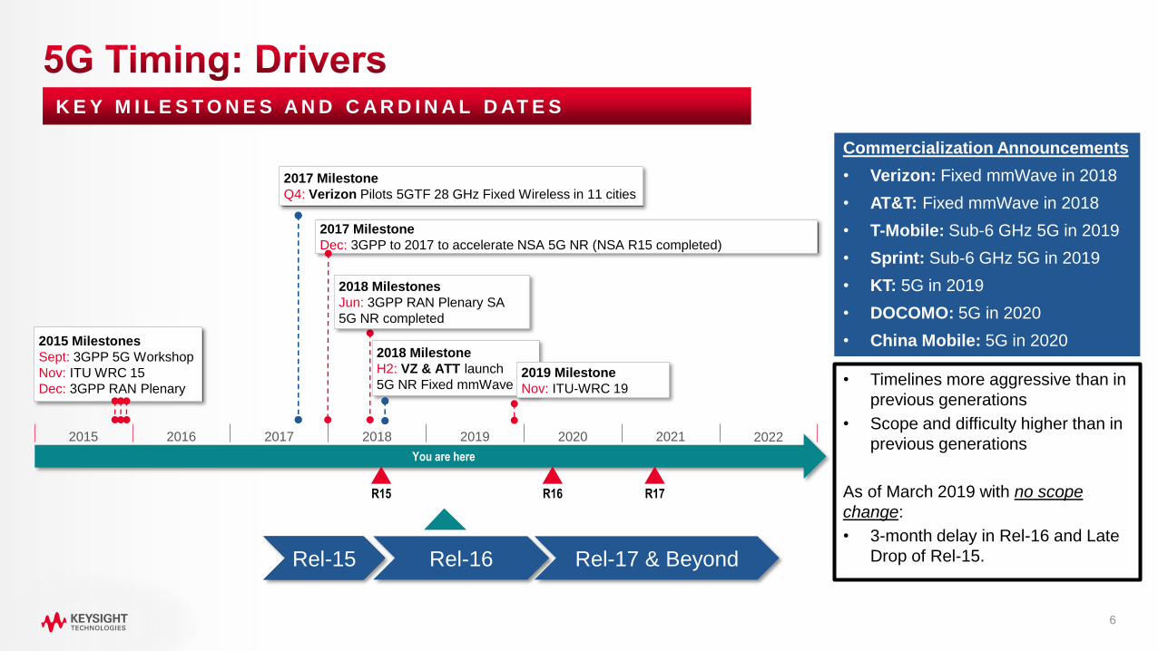
2018 Milestone
H2: VZ & ATT launch
5G NR Fixed mmWave
2017 Milestone
Dec: 3GPP to 2017 to accelerate NSA 5G NR (NSA R15 completed)
2017 Milestone
Q4: Verizon Pilots 5GTF 28 GHz Fixed Wireless in 11 cities
2015 2016 2017 2018 2019 20212020 2022
2018 Milestones
Jun: 3GPP RAN Plenary SA
5G NR completed
2015 Milestones
Sept: 3GPP 5G Workshop
Nov: ITU WRC 15
Dec: 3GPP RAN Plenary
K E Y M I L E S T O N E S A N D C A R D I N A L D AT E S
You are here
R15
Commercialization Announcements
• Verizon: Fixed mmWave in 2018
• AT&T: Fixed mmWave in 2018
• T-Mobile: Sub-6 GHz 5G in 2019
• Sprint: Sub-6 GHz 5G in 2019
• KT: 5G in 2019
• DOCOMO: 5G in 2020
• China Mobile: 5G in 2020
Rel. 15 Rel-16 Rel-17 & BeyondRel-15
• Timelines more aggressive than in
previous generations
• Scope and difficulty higher than in
previous generations
As of March 2019 with no scope
change:
• 3-month delay in Rel-16 and Late
Drop of Rel-15.
R16
2019 Milestone
Nov: ITU-WRC 19
R17

7
AVA I L A B I L I T Y O F G R E E N F I E L D T D D S P E C T R U M
5G NR Technology Introduction
* T-Mobile plans to use 600MHz spectrum which is an FDD band
5G Spectrum Availability < 6GHz
RegionNew Existing BW Total BW
FLOW FHIGH FLOW FHIGH MHz MHz
Korea 3400 3700 300 300
Europe2570 2620 50
4503400 3800 400
Japan
2496 2690 194
14943600 4200 3400 3600 800
4400 4900 500
US2496 2690 191
3443550 3700 (1) 150
China
2300 2400 100
7002555 2655 100
3300 3600 3400 3600 300
4800 5000 200
Un-licensed 5725 5875 150 150
5G Spectrum Availability mmWave
RegionNew Existing BW Total BW
FLOW FHIGH FLOW FHIGH GHz GHz
Korea 26.5 29.5 3.00 3.00
Europe
24.25 27.5 3.25
7.8531.8 33.40 1.6
40.5 43.5 3.00
Japan 27.50 29.50 2.0 2.0
US
27.50 28.35 0.85
3.8537.00 38.60 1.6
38.6 40.00 1.4
China24.75 27.5 2.75
8.2537.00 42.5 5.5
Un-licensed
43.5 47 3.5 3.5 (China)
64.0 71.0 57.0 64.0 7.0 14.0
Adapted from IWPC 5G UE, SWKS Mar 2017 (David Pehlke)

88
• 2 frequency ranges:
• FR1 (410 MHz – 7.125 GHz)
• Bands numbered from 1 to 255
• No longer can be commonly referred to as sub-6 GHz!
• FR2 (24.250 - 52.600 GHz) → Soon to be extended to 114.25 GHz
• Bands numbered from 257 to 511
• Commonly referred to as mmWave
• Scalability required for different use cases/frequency bands
• Scalable numerology - sub-frame structure and component carrier bandwidth
• Introduction of mini-slots for low latency
• Channel bandwidths up to 400 MHz for single component carrier
• 3D Beamforming antennas - MU-MIMO steerable on per UE basis, massive MIMO
• Layer 3 (OTA) based on 4G but enhanced for control plane efficiency
• Lower layers / 5G NR greatly enhanced for the required data rates, latency, and efficiency
AT A G L A N C E – K E Y D I S T I N C T I V E F E AT U R E S
FR2: NR band / SCS / UE Channel bandwidth
NR
Band
SCS
kHz
50
MHz
100
MHz
200
MHz
400
MHz
n25760 Yes Yes Yes N/A
120 Yes Yes Yes Yes
n25860 Yes Yes Yes N/A
120 Yes Yes Yes Yes
n26060 Yes Yes Yes N/A
120 Yes Yes Yes Yes
n26160 Yes Yes Yes N/A
120 Yes Yes Yes Yes
3GPP TS 38.521-2 Table 5.3.5-1

99
Specification Title
38.300 Overall Description
38.902 Study on New Radio Access Technology
38.211 Physical Channels and Modulation
38.212 Multiplexing and Channel Coding
38.213 Physical Layer Procedures for Control
38.214 Physical Layer Procedures for Data
38.321 NR Medium Access Control (MAC)
38.322 NR Radio Link Control (RLC)
38.323 NR Packet Data Convergence Protocol (PDCP)
37.324 NR Service Data Protocol (SDAP)
38.331 NR Radio Resource Control (RRC)
24.301 Non-Access Stratum (NAS)
33.501 Security Architecture and Procedures for 5G
37.340 NR Multi-connectivity Overall Description

1010
RAN Plenary is responsible for all Radio Access Networks, including their internal structures and functions, of
systems for evolved GERAN, UTRAN, E-UTRAN, 5GC and beyond. All groups participate in plenary meetings.
RAN WG Responsibilities
RAN1
Radio Layer 1
Specification of the physical layer of the radio interface – channels structures,
mapping transport channels to physical channels, multiplexing, modulation
schemes, etc
RAN2
Radio Layer 2 and Layer 3
Specification of the radio interface architecture and radio interface protocols –
interface between architecture and protocols
RAN3
Core, O&M Requirements
Overall architecture and radio interface protocols – defines next generation
interface protocols
RAN4
Radio Performance and Protocol
Development of UE and base station specifications, base station conformance
test specifications, and specifications for electromagnetic compatibility (EMC)
RAN5
Mobile Terminal Conformance Tests
Development of UE conformance test specifications including signaling and
protocol test cases, and inter-RAT procedures

1111
LTE (Based on 3GPP Rel-15) New Radio (Based on 3GPP Rel-15)
Frequency Band Sub-6 GHz FR1, FR2
Max Bandwidth (CC) 20 MHzFR1: 5, 10, 15, 20, 25, 30, 40, 50, 60, 80, 100 MHz
FR2: 50, 100, 200, 400 MHz
Max CCs 5 (Rel-10) / 32 (Rel-12). 5 current implementation 8
Subcarrier Spacing 15 kHz 2n · 15 kHz
Waveform CP-OFDM for DL; SC-FDMA for UL CP-OFDM (DL); CP-OFDM and DFT-s-OFDM (UL)
ModulationUp to 256 QAM DL (moving to 1024 QAM);
Up to 64 QAM ULUp to 256 QAM UL & DL
Max Number of
Subcarriers1200 3276
Subframe Length 1 ms (moving to 0.5 ms) 1 ms
Latency (Air Interface) 10 ms (moving to 5 ms) 1 ms
Slot Length 7 symbols in 500 µs14 symbols (duration depends on SC spacing)
2, 4 and 7 symbols for mini-slots
Channel Coding Turbo Code (data); TBCC (control) LDPC (data); Polar Codes (control)
Initial Access No beamforming Beamforming
MIMO Up to 8x8 Up to 8x8
Reference signals UE Specific DMRS and Cell Specific RS Front-loaded DMRS (UE-specific)
Duplexing FDD, Static TDD FDD, Static TDD, Dynamic TDD
1212
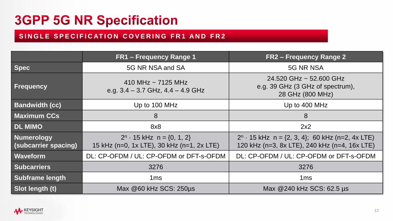
FR1 – Frequency Range 1 FR2 – Frequency Range 2
Spec 5G NR NSA and SA 5G NR NSA
Frequency410 MHz ~ 7125 MHz
e.g. 3.4 – 3.7 GHz, 4.4 – 4.9 GHz
24.520 GHz ~ 52.600 GHz
e.g. 39 GHz (3 GHz of spectrum),
28 GHz (800 MHz)
Bandwidth (cc) Up to 100 MHz Up to 400 MHz
Maximum CCs 8 8
DL MIMO 8x8 2x2
Numerology
(subcarrier spacing)
2n · 15 kHz n = {0, 1, 2}
15 kHz (n=0, 1x LTE), 30 kHz (n=1, 2x LTE)
2n · 15 kHz n = {2, 3, 4}; 60 kHz (n=2, 4x LTE)
120 kHz (n=3, 8x LTE), 240 kHz (n=4, 16x LTE)
Waveform DL: CP-OFDM / UL: CP-OFDM or DFT-s-OFDM DL: CP-OFDM / UL: CP-OFDM or DFT-s-OFDM
Subcarriers 3276 3276
Subframe length 1ms 1ms
Slot length (t) Max @60 kHz SCS: 250µs Max @240 kHz SCS: 62.5 µs
S I N G L E S P E C I F I C AT I O N C O V E R I N G F R 1 A N D F R 2

1313
• For FR1, 100 MHz is the maximum channel
bandwidth specified
Channel Bandwidth
5 MHz
10 MHz
15 MHz
20 MHz
25 MHz
30 MHz
40 MHz
50 MHz
60 MHz
80 MHz
100 MHz
3GPP TS 38.521-1 Table 6.1-1
NR Band / SCS / UE Channel Bandwidth
NR
Band
SCS
kHz50 MHz 100 MHz 200 MHz 400 MHz
n25760 Yes Yes Yes N/A
120 Yes Yes Yes Yes
n25860 Yes Yes Yes N/A
120 Yes Yes Yes Yes
n26060 Yes Yes Yes N/A
120 Yes Yes Yes Yes
n26160 Yes Yes Yes N/A
120 Yes Yes Yes Yes
3GPP TS 38.521-2 Table 5.3.5-1
• For FR2, 50, 100, 200 and 400 MHz channel bandwidths are
specified

1414
N O A R B I T R A R Y D E C I S I O N – D R I V E N B Y P R O P E R T I E S O F C H A N N E L
FR1 FR2
Deployment
Scenario
Macro cells
High user mobility
Small cells
Low user mobility
MIMO Order Up to 8x8 Typically 2x2
Number of
Simultaneous
Users
Tens of users
Large coverage
area
A few users
Small coverage area
Main BenefitSpatial multiplexing,
MU-MIMO
Beamforming for single
user
Channel
Characteristics
Rich multipath
propagation
A few propagation
paths
Spectral
Efficiency
High due to the
spatial multiplexing
Low spectral efficiency
(few users, high path
loss)

1515
Beamforming to
increase received
power and SNR
Transmit diversity for
improved qualityMIMO multi-layer
transmission for higher
data rates
Multi-user MIMO (UL/DL)
more users per cell
Spatial multiplexing
more users per cell

1616
• LTE coverage
• Large existing network deployment
• Wide coverage due to lower frequency range
• 5G network
• System deployment will take time
• Range is more restricted in higher frequency bands
• NSA - Dual Connectivity (DC) uses both systems for evolution,
reliability and geographical coverage
• Expectation: slow and smooth transition into 5G
J U S T A N I N T R O : M O R E D I S C U S S E D L AT E R
1717
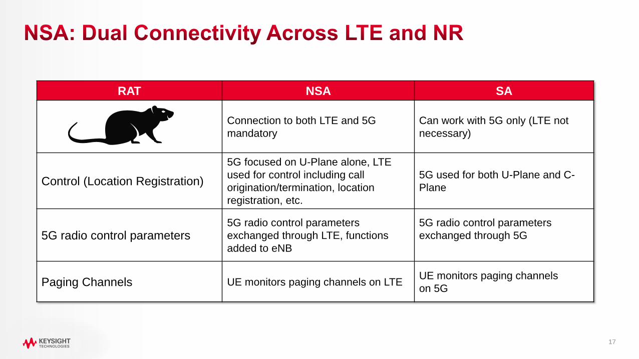
RAT NSA SA
Connection to both LTE and 5G
mandatory
Can work with 5G only (LTE not
necessary)
Control (Location Registration)
5G focused on U-Plane alone, LTE
used for control including call
origination/termination, location
registration, etc.
5G used for both U-Plane and C-
Plane
5G radio control parameters5G radio control parameters
exchanged through LTE, functions
added to eNB
5G radio control parameters
exchanged through 5G
Paging Channels UE monitors paging channels on LTE UE monitors paging channels
on 5G

1818
5 G N R S A
NR
RRC Connected
NR
RRC Inactive
NR
RRC Idle
Connection (de)activation
Suspend/Resume
Connection Establishment
/ReleaseConnection
Failure
• Device
• monitors control channels for data scheduling
• provides channel quality estimate to gNB
• provides neighbor cell measurements
• Device
• performs RAN based notification area updates
when moving outside the notification area
• stores the AS context
• Device
• acquires SI
• monitors paging
• performs neighbor cell measurements
• performs cell (re-)selection

1919
5 G N R S A
E-UTRA
RRC Connected
E-UTRA
RRC Idle
Connection
Establishment/Release
Reselection
Reselection
HandoverNR
RRC Connected
NR
RRC Inactive
NR
RRC Idle
Connection (de)activation
Suspend/Resume
Connection
Establishment/ReleaseConnection
Failure

2020
• Technology Overview & Timeline
• Carrier Aggregation & Bandwidth Adaptation
• Numerology & Frame Structure
• Waveforms & Modulations
• Protocol Structures, Layers, Signals & Channels
• Beams, Beamforming & Beam Management
• Initial Access Procedure, Example Call Flows
• Network Architecture, Deployment Options
• New Features Coming in Rel-16
A G E N D A

2121
• Maximum single-CC bandwidth is 400 MHz
• Maximum number of CCs is 8
Single-Carrier Operation Multi-Carrier Operation
Freq.
NW Channel BW
UE
ca
teg
ory
/ca
pa
bilit
y Freq.
NW Channel
BW
UE
ca
teg
ory
/ca
pa
bilit
y

2222
• Component Carriers may be in the same band and adjacent
• Or they could be in the same band, non-contiguous
• Or in different bands
Band A – sub-6 GHz Band B – mmWave (28 GHz)

2323
• RRC Connection and Registration only performed on Primary Component Carrier (PCC)
• Control channels (PDCCH and PUCCH) on Primary CC
• Data channels (PDSCH and PUSCH) on all component carriers
Downlink Uplink
PCCSCC SCC SCCPCC SCCSCC
PDCCH and PDSCHPDSCH
(optional PDCCH)PUCCH and PUSCH PUSCH
SCC

24
C O N T I G U O U S P H Y S I C A L R E S O U R C E B L O C K S ( P R B S )
• An Initial Bandwidth Part is signaled by PBCH
• It contains CORESET (Control Resource Set) and PDSCH
• The bandwidth part may or may not contain (Beamforming) SS/PBCH block
• Reserved resources can be configured within the bandwidth part
• One or multiple bandwidth part configurations for each component carrier can be semi-statically
signaled to a UE
• Only one BWP in DL and one in UL is active at a given time
• Other configuration parameters include:
• Numerology: CP type, subcarrier spacing
• Frequency location: the offset between BWP and a reference point within cell BW
• Bandwidth size: in terms of PRBs

2525
BWP activation/deactivation:
• UE may be configured with up to 4 DL and 4 UL bandwidth parts
• Activation by dedicated RRC signaling
• Activation/deactivation by DCI with explicit indication
• Activation/deactivation by a timer for a UE to switch its active DL BWP to a default BWP
B A N D W I D T H PA R T U S E C A S E S
Overall carrier
BWP
2. Supporting Reduced UE Energy Consumption
Overall carrier
BWP # 1
BWP # 2
3. Supporting Different NumerologiesOverall carrier
BWP # 1
(num erology # 1)
BWP # 2
(num erology # 2)
Overall carrier
BWP # 1 BWP # 2
Som ething com pletely unknown
Overall carrier
BWP
Som ething new and not yet defined
?
4. Supporting Non-contiguous Spectrum
5. Supporting Forward Compatibility
1. Supporting Reduced UE Bandwidth Capability

2626
• The UE may be configured with additional supplemental uplink
• An additional lower frequency band UL carrier
• Enhances data rate and deployment range in NSA mode
• Improve performance at cell edge in SA mode
• Supplemental uplink is different from carrier aggregation
because the UE may transmit on
• The supplemental uplink OR
• UL component carrier
(but not on both at the same time)
Operating
Band
Uplink (UL)
BS Receive / UE Transmit
Downlink (DL)
BS Transmit / UE Receive
Duplex
Mode
n80 1710 – 1785 MHz N/A SUL
n81 880 – 915 MHz N/A SUL
n82 832 – 862 MHz N/A SUL
n83 703 – 748 MHz N/A SUL
n84 1920 – 1980 MHz N/A SUL
n86 1710 – 1780 MHz N/A SUL

2727
• Technology Overview & Timeline
• Carrier Aggregation & Bandwidth Adaptation
• Numerology & Frame Structure
• Waveforms & Modulations
• Protocol Structures, Layers, Signals & Channels
• Beams, Beamforming & Beam Management
• Initial Access Procedure, Example Call Flows
• Network Architecture, Deployment Options
• New Features Coming in Rel-16
A G E N D A

2828
FR1 Operation
FR2 Operation
S C A L A B L E S U B - C A R R I E R S PA C I N G ( S C S ) - Δ F
µ Δf = 2µ·15 kHz Cyclic Prefix
0 15 kHz Normal 275 1
1 30 kHz Normal 275 2
2 60 kHz Normal, Extended 275 4
Initial
Access Data
µ Δf = 2µ·15 kHz Cyclic Prefix
2 60 kHz Normal, Extended 275 4
3 120 kHz Normal 275 8
4 240 kHz Normal 138 16
5 480 kHz Normal 69 32
DataInitial
Access
max, µ
RBNsubframe, µ
slotN
max, µ
RBNsubframe, µ
slotN
29
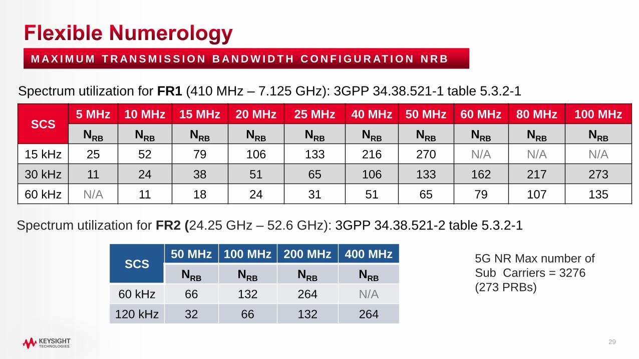
M A X I M U M T R A N S M I S S I O N B A N D W I D T H C O N F I G U R AT I O N N R B
5G NR Max number of
Sub Carriers = 3276
(273 PRBs)
Spectrum utilization for FR1 (410 MHz – 7.125 GHz): 3GPP 34.38.521-1 table 5.3.2-1
SCS5 MHz 10 MHz 15 MHz 20 MHz 25 MHz 40 MHz 50 MHz 60 MHz 80 MHz 100 MHz
NRB NRB NRB NRB NRB NRB NRB NRB NRB NRB
15 kHz 25 52 79 106 133 216 270 N/A N/A N/A
30 kHz 11 24 38 51 65 106 133 162 217 273
60 kHz N/A 11 18 24 31 51 65 79 107 135
Spectrum utilization for FR2 (24.25 GHz – 52.6 GHz): 3GPP 34.38.521-2 table 5.3.2-1
SCS50 MHz 100 MHz 200 MHz 400 MHz
NRB NRB NRB NRB
60 kHz 66 132 264 N/A
120 kHz 32 66 132 264
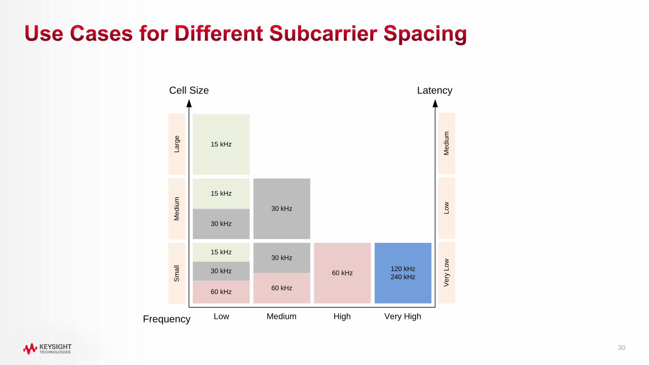
30
Cell Size
La
rge
Me
diu
mS
ma
ll
15 kHz
15 kHz
15 kHz
30 kHz
60 kHz
30 kHz
30 kHz
30 kHz
60 kHz
60 kHz120 kHz
240 kHz
Latency
Me
diu
mL
ow
Ve
ry L
ow
Low Medium High Very HighFrequency

3131
• Sub-carrier spacing = 2μ x 15 kHz
• Slot is 14 symbols - slot length decreases as subcarrier spacing increases
µ Subcarrier spacing Slot lengthNumber of slots
per subframeUsage
0 15 kHz 1 ms 1 Outdoor large cell <3 GHz
1 30 kHz 500 μs 2 Outdoor small cell >3 GHz
2 60 kHz 250 μs 4Indoor wideband cell 5 GHz
Small cell above 6 GHz
3 120 kHz 125 μs 8 Very small cell 28 GHz
4 240 kHz 62.5 μs 16Indoor very small cell
mmWave
FR2
FR1
12
0 k
Hz
15 kHz
SCS
30 kHz
SCS
30 kHz
SCS
60
kH
z
SC
S
60
kH
z
SC
S
60
kH
z
SC
S
60
kH
z
SC
S
12
0 k
Hz
12
0 k
Hz
12
0 k
Hz
12
0 k
Hz
12
0 k
Hz
12
0 k
Hz
12
0 k
Hz
1 m s
1 m s500 µs 250 µs 125 µs

3232
• SCS: 15 kHz*2n
• Frame: 10 ms
• Subframe: Reference period of 1 ms
• Slot (slot based scheduling)
• 14 OFDM symbols, or 12 with extended CP
• One possible scheduling unit
• Slot length scales with the subcarrier spacing
• Mini-Slot (non-slot based scheduling)
• DL: 7, 4 or 2 OFDM symbols, can start immediately
• UL: any length
• Minimum scheduling unit
F R A M E S T R U C T U R E & N U M E R O L O G Y
120 kHz
SLOT14 sym
250 µs
60 kHz
SLOT14 symbols
500 µs
30 kHz
SLOT14 symbols
1 ms
15 kHz
1 ms
SUBFRAME
SLO
T
14
s
125 µs
240 kHz S
LO
T
14
s
62.5 µs
Slot structure is flexible to provide for better
spectrum utilization

33
1 5 K H Z V S 1 2 0 K H Z S U B C A R R I E R S PA C I N G

3434
Slot Format Indication (SFI) informs the UE of the current format (56 formats defined)
• Downlink only (Slot Format 0, used in FDD)
• Uplink only (Slot Format 1, Used in FDD)
• Flexible: Downlink and Uplink (static, semi-static (RRC) or dynamically scheduled (DCI))
F D D A N D T D D S L O T S , A N D A M I X O F
Mini-slot
(2,4,7 symbols)
ULDL symbols ULDL symbolsTDD at 28 GHz
UL
symbolsDL symbolsTDD at 3 GHz
Downlink symbols
Uplink symbolsFDD at 700 MHz
Not tied to the frame
structure
Examples:
……
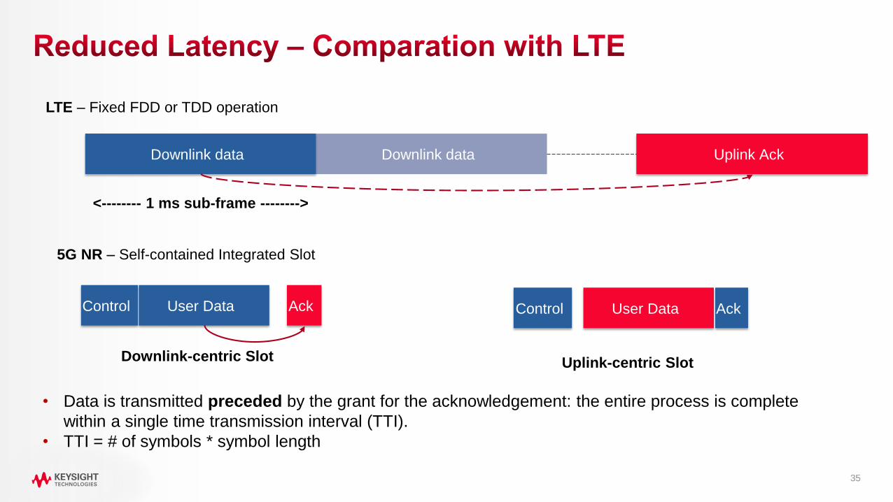
3535
Downlink data
LTE – Fixed FDD or TDD operation
Uplink AckDownlink data
<-------- 1 ms sub-frame -------->
Control User Data Ack
5G NR – Self-contained Integrated Slot
Downlink-centric Slot
Control User Data Ack
Uplink-centric Slot
• Data is transmitted preceded by the grant for the acknowledgement: the entire process is complete
within a single time transmission interval (TTI).
• TTI = # of symbols * symbol length

3636
• Technology Overview & Timeline
• Carrier Aggregation & Bandwidth Adaptation
• Numerology & Frame Structure
• Waveforms & Modulations
• Protocol Structures, Layers, Signals & Channels
• Beams, Beamforming & Beam Management
• Initial Access Procedure, Example Call Flows
• Network Architecture, Deployment Options
• New Features Coming in Rel-16
A G E N D A

3737
The plan to introduce cellular services in frequency
bands >6 GHz is driving an abrupt and
unprecedented change in how devices and systems
have to be designed, operated and tested.
• To overcome these losses and provide a realistic link
budget, it is necessary to use high gain antennas
comprised of multiple elements at both ends of the link
• High gain antennas create narrow beam width signals
• Radio propagation at mmWave is very different: very
sparse and spatially dynamic, unlike rich multipath with
Rayleigh fading
Question: Is it better to have high gain or low gain antenna?
The Friis propagation equation predicts
losses at mmWave frequencies:
Path Loss ~ f 2

3838
• The simplest use of large antenna arrays at the base station is beamsteering
– create narrow beams within the cell to direct signals to specific locations,
possibly with reflections involved
• A key difference between beamsteering and beamforming is steering only
needs to know the direction of the user while beamforming requires precise
real-time channel state information (CSI)
• To then exploit the channel, beamforming requires full digital control of
the amplitude and phase of every antenna element while beamsteering
can be done using simple analog phase shifters
• In a predominantly line of sight channel with several users in different
locations, beamforming would simultaneously generate a beam towards each
user much like beamsteering
• The benefits of beamforming become more apparent as the channel becomes
more scattered, which is when simpler beamsteering is less effective
B E A M S T E E R I N G V S . B E A M F O R M I N G
Beamforming
Beamsteering

3939
D O W N L I N K S Y N C H R O N I Z AT I O N S I G N A L ( S S ) B L O C K S , B U R S T S , A N D S E T S
PSS = Primary Synchronization Signal
SSS = Secondary Synchronization Signal
PBCH = Physical Broadcast Channel
SS Block
-1 symbol PSS
-1 symbol SSS
-2 symbols PBCH
SS Burst
-Multiple SS Blocks
-Transmission is periodic (20 ms by default)
-Confined within a 5 ms window
SS Burst
SS Block Periodicity (20 m s)
SS
Blo
ck
SS
Blo
ck
SS
Blo
ck
SS
Blo
ck
...
SS
Blo
ck
SS
Blo
ck
SS
Blo
ck
SS
Blo
ck
...
SS
Blo
ck
SS
Blo
ck
SS
Blo
ck
SS
Blo
ck
...
SS
Blo
ck
SS
Blo
ck
SS
Blo
ck
SS
Blo
ck
...
5 m s window
(half-fram e)
. . .
SS Burst

4040
• All SSB are transmitted on the same single-antenna port
• Each SSB within a SS Burst Set is potentially
transmitted on a different beam
• The same beam pattern is repeated for each SSB
within the SS Burst Set period (20 ms by default)
• The UE identifies a SSB within the Burst Set by using:
• The time index carried by the PBCH DMRS
• The rest of the SSB index carried by the PBCH data
• The best SSB is used to respond to with the PRACH
B E A M S W E E P I N G
SS Block 1 SS Block 2 SS Block 3 SS Block 4 SS Block 5
Time

4141
Tim e
P
S
S
P
B
C
H
S
S
S
P
B
C
H
SS Block
SS Block 1 SS Block 2 SS Block 3 SS Block 4 SS Block 5
TRxP
DL
SS Block 1
DL
SS Block 2
DL
SS Block 3
DL
SS Block 4
UE
X P
UL 1 UL 2 UL 3 UL 4
P
Rx PSS, SSS and PBCH PRACH Transm ission
Sam e Tx beam
direct ion as in
the DL Tx
beam
Mapping between DL SS Blocks and corresponding UL resources for
PRACH
...

4242
S Y N C H R O N I Z AT I O N , R A N D O M A C C E S S A N D U E - S P E C I F I C B E A M F O R M I N G
Synchronization Signals
System Information
Basic information for all UEs
Beam-sweeping
transmission
Random Access PreambleSingle-beam
or Beam-
sweeping
Beam-sweeping
receptionRandom Access Response & System
Information
Required only for UEs after random access
Beam-sweeping
transmission
UE-specific
selected beam
Data and control channelsUE-specific
beamforming
Wide Coverage
UE-Specific
Coverage
gNB UE

43
M O B I L I T Y A N D T H E C H A L L E N G E O F D I R E C T I O N A L A N T E N N A S
Connected
High Gain
Tracking
Search
Acquisition
Tracking
Feedback
Refinement
Switch

4444
• The network and device will use beamforming
antennas (maybe as low as 12 degrees?)
• Narrow beams increase the received power
(Signal-to-Noise) level
• Beams to different UEs can re-use the same
time and frequency resources
• All common and dedicated channels are
transmitted (and received) over beams
• Beams are bilateral for (t, f, (x,y,z)) – TDD
operation only

4545
• mmWave has great potential (spectrum!)
• mmWave signals do not bend around corners (diffract) and are easily blocked or attenuated
• mmWave signals do bounce (reflect) readily giving rise to local scattering (multipath)
• mmWave signals act more like light rays so can be directed using special antennas
• Path loss through the air is much greater at mmWave than at LTE bands
• Changing from 1 GHz to 28 GHz path loss increases by 28 dB over 1 m
Cables are lossy and expensive, galvanic connectors may not
be exposed/available, 3GPP requires FR2 tests to be radiated
Therefore, testing will be mostly performed over the air

4646
• Technology Overview & Timeline
• Carrier Aggregation & Bandwidth Adaptation
• Numerology & Frame Structure
• Waveforms & Modulations
• Protocol Structures, Layers, Signals & Channels
• Beams, Beamforming & Beam Management
• Initial Access Procedure, Example Call Flows
• Network Architecture, Deployment Options
• New Features Coming in Rel-16
A G E N D A

47
gNB
Connected
NR Add
Successful
NR Initial Access, Msg1-Msg4
LTE Attach
Procedure
LTE Attach
Complete
UE LTE
Connected

4848
• Technology Overview & Timeline
• Carrier Aggregation & Bandwidth Adaptation
• Numerology & Frame Structure
• Waveforms & Modulations
• Protocol Structures, Layers, Signals & Channels
• Beams, Beamforming & Beam Management
• Initial Access Procedure, Example Call Flows
• Network Architecture, Deployment Options
• New Features Coming in Rel-16
A G E N D A

4949
S TA R T W I T H N S A
Rel-15 Early Drop (December 2017)
• NR NSA – eNB as master node
• 4G Core Network (EPC)
• Enhanced LTE (eLTE)
Rel-15 (June 2018)
• 5G Core Network
• Enhanced LTE (eLTE)
• NR SA and NSA Combinations

50
O P T I O N S 3 / 3 A / 3 X
• Dual Connectivity with EPC: E-UTRA-NR Dual Connectivity (EN-DC)
• Master Node: eNB (LTE)
• Secondary Node: gNB (5G NR)
x2 interface No load-sharing PDCP split

51
O P T I O N S 7 / 7 A / 7 X
• Dual Connectivity with NG-RAN: NG-RAN E-UTRA-NR Dual Connectivity (NGEN-DC)
• Master Node: ng-eNB (eLTE) – eNB evolved (eLTE)
• Secondary Node: gNB (5G NR)

52
O P T I O N S 4 / 4 A
• Dual Connectivity with NG-RAN: NR-E-UTRA Dual Connectivity (NE-DC)
• Master Node: gNB (5G NR)
• Secondary Node: ng-eNB (eLTE)

5353
• Technology Overview & Timeline
• Carrier Aggregation & Bandwidth Adaptation
• Numerology & Frame Structure
• Waveforms & Modulations
• Protocol Structures, Layers, Signals & Channels
• Beams, Beamforming & Beam Management
• Initial Access Procedure, Example Call Flows
• Network Architecture, Deployment Options
• New Features Coming in Rel-16
A G E N D A
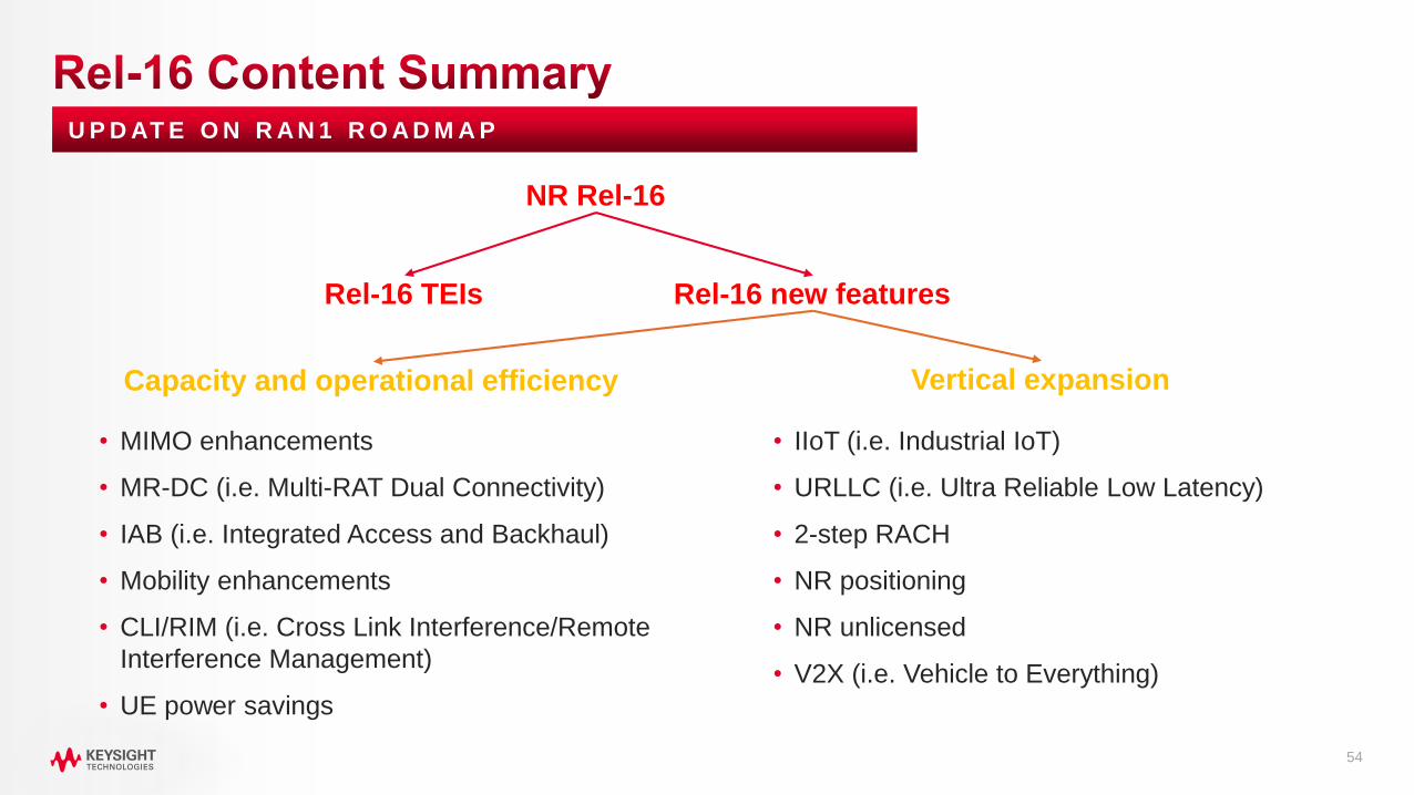
54
U P D AT E O N R A N 1 R O A D M A P
• IIoT (i.e. Industrial IoT)
• URLLC (i.e. Ultra Reliable Low Latency)
• 2-step RACH
• NR positioning
• NR unlicensed
• V2X (i.e. Vehicle to Everything)
• MIMO enhancements
• MR-DC (i.e. Multi-RAT Dual Connectivity)
• IAB (i.e. Integrated Access and Backhaul)
• Mobility enhancements
• CLI/RIM (i.e. Cross Link Interference/Remote
Interference Management)
• UE power savings
Rel-16 new features
Capacity and operational efficiency Vertical expansion
Rel-16 TEIs
NR Rel-16

55
• NR-Light and Small Data Transfer Optimization
• NR optimization for MTC type of devices
• Mostly related to power saving aspects and inactive data transmission
• Sidelink enhancements for NR
• Focus on areas relating to V2X services, commercial and critical communications
• Frequency Range 2
• NR for above 52.6GHz
• Will include discussions and decisions on waveforms for frequencies higher than currently standardized
• Inclusion of 60GHz unlicensed spectrum
• Coverage enhancements
• Work on clarifications for all scenarios which are focusing on extreme coverage including both indoor and
wide area
U P D AT E O N R A N 1 R O A D M A P
Not all these work areas will
be included in the final
approved Rel-17 package

56
• NB-IoT, eMTC, Industrial IoT, URLLC enhancements
• Enhancements related to current commercial needs and deployments
• Small leftovers from Rel-16 (e.g. header compression)
• NR for Non-Terrestrial Networks and Integrated Access Backhaul (IAB) enhancements
• Should include mobile IAB,
• RAN data collection enhancements
• Focuses on data collection related to enabling of Artificial Intelligence
• Power Saving Enhancements
• Focus on power saving related to smartphones and network-related power saving aspects
• Positioning Enhancements
• Include further adjustments for more accurate positioning services (e.g. 3D-positioning and cm-level
accuracy, latency and reliability improvements)
• Specific areas: IoT, V2X, factory positioning
U P D AT E O N R A N 1 R O A D M A P
Not all these work areas will
be included in the final
approved Rel-17 package

5757
• Standards will continue to evolve through
Rel-16 and beyond: your test solutions
need to be flexible and scalable
• Higher frequencies, wider channel
bandwidths, and dual connectivity
increase the number of test cases and
test complexity
• mmWave and MIMO introduce new OTA
test requirements for 5G NR devices and
base stations
• New initial access and control procedures
will require more testing
U N D E R S TA N D I N G T H E R O A D A H E A D

58
• 3GPP – Third Generation Partnership Project
• 5G NR – 5th Generation New Radio
• BI – Beam Index
• BLER – Block Error Rate
• BW – Bandwidth
• CPE – Customer Premise Equipment
• CSI-RS - Channel State Information Reference Signal
• DL – Downlink
• eNB – eNodeB
• FCC – Federal Communications Commission
• gNB – gNodeB
• KPI – Key Performance Indicator
• MAC – Media Access Control
• MCS – Modulation and coding scheme
• MIMO – Multiple Input Multiple Output
• mmWave – Millimeter-wave
• NEM – Network Equipment Manufacturer
• OFDM – Orthogonal Frequency Division Multiplexing
• PBCH – Primary Broadcast Channel
• PBCH DMRS – PBCH Demodulation Reference Signal
• PDSCH – Physical Downlink Shared Channel
• PRACH – Physical Random Access Channel
• PRB – Physical Resource Block
• PSS – Primary Synchronization Signal
• QoE – Quality of Experience
• QoS – Quality of Service
• RACH – Random Access Channel
• RAN – Radio Access Network
• RAT – Radio Access Technology
• RRC – Radio Resource Control
• SCS – Sub-carrier spacing
• SRS (UL) - Sounding Reference Signal
• SSB – Synchronization Signal Block
• SS-RSRP – SS Reference Signal Received Power
• SS-RSRQ – SS Reference Signal Received Quality
• SS-SINR – SS Signal-to-Noise and Interference Ratio
• SSS – Secondary Synchronization Signal
• TRS – Tracking Reference Signal
• TX – Transmitter
• UE – User Equipment
• UL – Uplink

59
Digital Conformance Test
Physical Layer Design and Test Solutions
5G Signaling Validation Test
5G Network Test
System-Level Simulation Component Characterization
RF and mmWave OTA TestParametric Signal Test Manufacturing Test Automation
Radio Signaling Test5G NR Protocol Validation
Drive Test and Analytics UE Emulation & Load Test Network Simulation & Test
5G NR Conformance Test

6060
• 3GPP Webpage www.3gpp.org
• Keysight Solutions www.keysight.com/find/5G
• Testing 5G NR Device OTA Throughput
Download Application Note
• Copy of these slides
www.keysight.com/find/5GBootCampPresentations

61