underground/submarine cable protection using a … cable protection using a negative-sequence...
TRANSCRIPT

Underground/Submarine Cable Protection Using a Negative-Sequence Directional
Comparison Scheme
Jesús Vargas INELAP-PQE.
Armando Guzmán Schweitzer Engineering Laboratories, Inc.
Jorge Robles Comision Federal de Electricidad
Revised edition released January 2000
Originally presented at the 26th Annual Western Protective Relay Conference, October 1999

1
UNDERGROUND/SUBMARINE CABLE PROTECTION USING A NEGATIVE-SEQUENCE DIRECTIONAL
COMPARISON SCHEME Jesús Vargas
INELAP-PQE. Guadalajara, Jal. Mexico
Armando Guzmán Schweitzer Engineering
Laboratories Pullman, WA USA
Jorge Robles Comision Federal de
Electricidad Mexico, D.F. Mexico
ABSTRACT Protective relaying requirements for underground and submarine cables are different from those for overhead lines. This paper analyzes the application of directional comparison schemes to protect two 34.5 kV submarine cables. These cables are 24-km long and connect Cozumel Island to Mexico’s mainland network. The paper discusses cable modeling using symmetrical components and analyzes the performance of a negative-sequence directional element during cable fault conditions.
INTRODUCTION Traditionally, current-differential relays have protected cables in transmission and distribution applications. These applications also require directional overcurrent or distance relays to provide protection when the communications channel is out-of-service.
This paper proposes an alternative solution for unbalanced fault protection. The solution is based on negative-sequence directional relays in a directional comparison scheme. This solution provides excellent fault resistance coverage and does not require additional backup protection. The paper also analyzes the performance of the directional relay in cable applications when the cable admittance is not negligible.
UNDERGROUND AND SUBMARINE CABLE PROTECTION Power cables are the most reliable means of connecting different equipment in an electric system [1]. They can be used as transmission or distribution links. We expect more power cable applications in electric systems because of advances in cross-linked polyethylene (XLPE) cable technology, environmental restrictions, and right-of-way availability.
Power cables require protection for overload and short-circuit current conditions. Power cable protection applications must consider different cable impedance characteristics and configurations.

2
Cable Types [2]
Pipe–Type
This cable consists of three conductor-shielded cables, each with a copper conductor, impregnated paper-wrapped insulation, semiconductive tape, and skid wires. The cables are installed in a steel pipe, which is coated on the outside to prevent corrosion.
Self-Contained Fluid Filled (SCFF)
These cables consist of three single-phase cables, each having a copper conductor with a hollow core. The hollow core permits fluid pressurization with a dielectric fluid at pressures of between 15 to 40 psi (pounds per square inch) or at a high pressure of about 200 psi, depending on the application. Cables are typically insulated with impregnated paper and have a lead or aluminum sheath to prevent the intrusion of moisture and to withstand fluid pressure.
Solid Dielectric
These cables consist of either three single-phase cables or three single conductors, each with its own insulation installed in a common armor.
The cable is made of copper or aluminum conductors with XLPE or Ethylene Propylene Rubber (EPR) insulation and a moisture-impervious outer sheath. XLPE cables, such as the one shown in Figure 1, are preferred for both transmission and distribution lines. Medium-voltage cables are protected with an outer sheath of polyvinyl chloride (PVC) or XLPE.
Moisturized atmosphere (water, salt, pollution, etc.) under high electrical stress causes the recognized water tree phenomenon in insulation. Because this phenomenon breaks down insulation in a relatively short operating period, high-voltage XLPE cables need metallic sheath moisture barriers under outer sheaths. Metallic sheaths can be aluminum (Al), stainless steel, lead (Pb), Al-laminated tape, or Pb-laminated tape.
Conductor
ScreenConductor
Insulation
ScreenInsulation
MetallicSheath
OuterSheath
6094: 001 Figure 1: XLPE Cable Construction.

3
Short-Circuit Current Protection of Cables
A cable must be protected against overheating caused by excessive short-circuit current flowing in its conductor. The fault point may be on the cable itself or on any other part of the electric system.
During a phase fault, the I2R losses in the phase conductor raise the temperature of the conductor and then of the insulation materials, screens, and surroundings. During a ground fault, the I2R losses in both the phase conductor and sheath elevate the temperature in a manner similar to that of phase faults.
During the flow of short-circuit current, the conductor temperature should not be permitted to rise to the point where it may damage the insulating materials. Cable protection during short-circuit conditions limits cable damage, if the fault is in the cable, and/or limits the amount of heat transferred from the metallic conductors to the insulation and other materials.
The high cost of power cables justifies the use of communications-assisted schemes. In general, schemes for overhead line protection and underground cable protection are the same. However, we must analyze and understand the differences between the two applications to properly protect power cables.
The three basic pilot cable protection relay schemes are: Current Differential, Phase Comparison, and Directional Comparison.
Current Differential
The current differential protection scheme may consist of three segregated-phase restraint differential elements or one restraint differential element that combines information from the three phases. These differential elements use operating and restraint quantities obtained from the local and remote-end currents. The operating quantity is the magnitude of the vectorial sum of these currents. The restraint quantity is usually the scalar sum of the same currents. The current differential relay uses the operating and restraint quantities to form a restraint-type characteristic. The relay characteristic defines an internal fault region. If the values of the operating and restraint quantities lie inside the internal fault region, the relay declares a tripping condition.
The differential scheme frequently is used for cable protection because this scheme is less dependent on cable characteristics. Following are the main characteristics of the current differential scheme:
a. It does not provide backup protection. b. Its availability depends upon communications channel performance. c. It only requires current signals.
d. It needs a communications channel with adequate bandwidth to transmit and receive current information.
e. It requires minimum settings; the settings must consider the effect of line charging currents.
f. The segregated-phase scheme has limited fault resistance coverage.
g. It is immune to out-of-step conditions and current reversals.
h. It requires special security logic for external fault conditions with current transformer (CT) saturation.
4
Phase Comparison
This scheme compares the phase angle between the currents at both ends of the cable. One phase comparison approach uses a combined signal that provides information for all fault types. In this scheme the composed signal is passed through a squaring amplifier to obtain a square wave signal that contains phase angle information. The relay compares the local squared signal against the remote squared signals; if the coincidence of the two signals is greater than a certain value, e.g., 90°, the scheme declares an internal fault condition.
This scheme has been very popular in the past because it has minimal communications channel requirements. Because the current signals contain phase angle information, this scheme is more secure than the current differential scheme for external fault conditions with CT saturation. All other characteristics are the same as in the current differential scheme.
Directional Comparison
Directional comparison schemes use different types of measuring units (directional elements, distance elements) at each end of the cable. These measuring units determine the fault direction. This scheme compares the fault direction information at each end of the cable to determine if there is a cable fault.
Frequently, these schemes use distance elements in power cable applications. This approach must consider the following facts:
a. The power cable impedance is less than the overhead line impedance because the phase conductor spacing in cables is less than the spacing in overhead lines. In some cases, the impedance may be less than the minimum distance relay setting value.
b. The cable zero-sequence impedance angle is less than the zero-sequence impedance angle for overhead lines. The zero-sequence angle compensation requires a large setting range that accommodates all possible cable angles.
Directional elements that operate with sequence-component quantities provide another possibility for a directional comparison scheme implementation. We will analyze the application of a negative-sequence directional element for power cable protection later in this paper. Following are the main characteristics of a directional comparison scheme:
a. The measuring units provide main and backup protection.
b. Loss of the communications channel only disables directional comparison functions, but does not disable directional protection functions for local and remote backup.
c. It requires voltage and current signals in both ends of the line.
d. Permissive Overreaching Transfer Trip (POTT) schemes normally operate with Frequency Shift Keying (FSK) communications channels.
e. In the case of pipe-type cables or cables in magnetic conduit, zero-sequence impedance is not constant and depends on the current flowing through the cable.
f. Charging current must be considered when setting the phase elements, to avoid a relay misoperation.
g. Negative-sequence component directional elements provide excellent fault resistance coverage [3]. These elements do not need to be desensitized to the effects of charging current.

5
CABLE CHARACTERISTICS Cable characteristics are an important factor in evaluating protective schemes for power cable applications. Additionally, we need to calculate the positive-, negative-, and zero-sequence inductive impedances and capacitance admittances to determine scheme settings [4, 5, 6]. In three-conductor cable applications, we can neglect cable asymmetries, but we must consider these asymmetries when applying sequence directional elements to protect single-conductor cables [7]. Let us next focus our attention on single-conductor cables.
Single-Conductor Cables
6094: 002
riro
Is
Ic
Sab
Sca
Sbc
3GMD = Sab Sbc Sca
Sheath rs, Xs
ConductorZc = rc + jXc
Figure 2: Group of Three Single-Conductor Cables.
Figure 2 shows a group of three single-conductor cables, one for each phase. The voltage drop due to the current flowing through the conductor is:
mscc XIjZIV ⋅⋅−⋅= Equation 1
The voltage drop along the sheath is zero with the sheath grounded:
( ) mcsss XIjIXjr0 ⋅⋅−⋅⋅+= Equation 2

6
where:
Zc = Conductor impedance (Ω)
rs = Sheath AC resistance (Ω)
Xs = Self-reactance of the sheath (Ω)
Xm = Mutual reactance between the conductor and the sheath (Ω)
Is = Sheath current (A)
Ic = Conductor current (A)
Sheath reactance, Xs, and mutual reactance, Xm, are equal when the conductor is concentric within the sheath. Solving Equation 2 for Is, and replacing Xm for Xs:
ms
mcs Xjr
XIjI
⋅+⋅⋅+
= Equation 3
Substitution of Is in Equation 1 gives:
mms
mccc X
XjrXIjjZIV ⋅⎟⎟
⎠
⎞⎜⎜⎝
⎛⋅+⋅⋅
⋅−⋅= Equation 4
The conductor impedance, Zc, is equal to rc + jXc. Substitution of the conductor resistance, rc, and the conductor reactance, Xc, in Equation 4 gives:
c2m
2s
3m
c2m
2s
2ms
c IXr
XXjXr
XrrV ⋅⎥⎥⎦
⎤
⎢⎢⎣
⎡⎟⎟⎠
⎞⎜⎜⎝
⎛
+−⋅+⎟⎟
⎠
⎞⎜⎜⎝
⎛
+⋅
+= Equation 5
( ) ( )[ ] cshcshc IXXjrrV ⋅+⋅++= Equation 6
where rsh in Equation 6 represents sheath losses caused by voltages the conductor current induced in the sheath. These voltages create sheath currents that increase the conductor resistance. Xsh in Equation 6 represents a reactance correction because of the presence of sheath currents. It has a negative sign because the sheath current direction is opposite to the conductor current direction.
Resistance Components
From Equation 5, the ac resistance of a single conductor in a group of three conductors is:
2m
2s
2ms
c XrXrrr+⋅
+= Equation 7
The mutual reactance, Xm, for a single conductor is [8]:
km/phase/rr
GMD2logf002893.0Xio
m Ω+
⋅⋅⋅= Equation 8

7
where:
f = System frequency (Hz)
GMD = Geometric Mean Distance (m)
ro = Sheath outer radius (m)
ri = Sheath inner radius (m)
The sheath resistance is [6]:
( ) ( )ioios rrrr
kr−⋅+
= Equation 9
where:
k = Function (sheath material)
The most important characteristics of the resistance components are:
a. Cable resistance is greater than the conductor resistance itself.
b. Cable resistance depends on GMD.
c. Cable resistance depends on the sheath geometry and material.
d. If the sheath is solidly bonded, as in Option in Figure 3 [9], its resistance may be 50–90 percent of the conductor resistance. Sheath insulation in one or two places reduces resistance, but produces high sheath voltages that may increase electrolysis or present hazardous conditions. The bonding method of cable shielding is also related to the cable current-carrying capacity.
I ndu
ced
Shie
ldV
olta
ge
3216094: 003
1 Single Point
3
2
Solid Bonding
Cross Bonding
Bonding
I J
Current Carrying Capacity : I > I > I
3
2
1
N J N J
I J = Insulated Joint
N J = Noninsulated JointN J
Figure 3: Bonding Method of Cable Shielding.
8
Reactance Components
From Equation 5 the reactance of a single conductor in a group of three conductors is:
shc2m
2s
3m
c XXXr
XXX +=+
−= Equation 10
The conductor reactance, Xc, for a single conductor is [8]:
km/phase/GMR
GMDlogf002893.0Xcond
c Ω⋅⋅= Equation 11
where:
GMRcond = Geometric Mean Radius (m)
The most important characteristics of the reactance components are:
a. The cable reactance, X, is smaller than the simple conductor reactance, Xc, due to sheath mutual coupling.
b. The closer the phase conductors are to each other, the smaller the conductor reactance, Xc.
c. The cable reactance reduction, Xsh, depends on the mutual reactance, Xm, which is a function of GMD. Xsh also depends on the sheath resistance, rs, which is a function of the sheath geometry and material.
d. If the sheath is insulated, as in Option in Figure 3, or discontinuous, as in Option in the same figure, the sheath currents are negligible. In these cases X = Xc because rsh has a large value.
Zero-Sequence Impedance
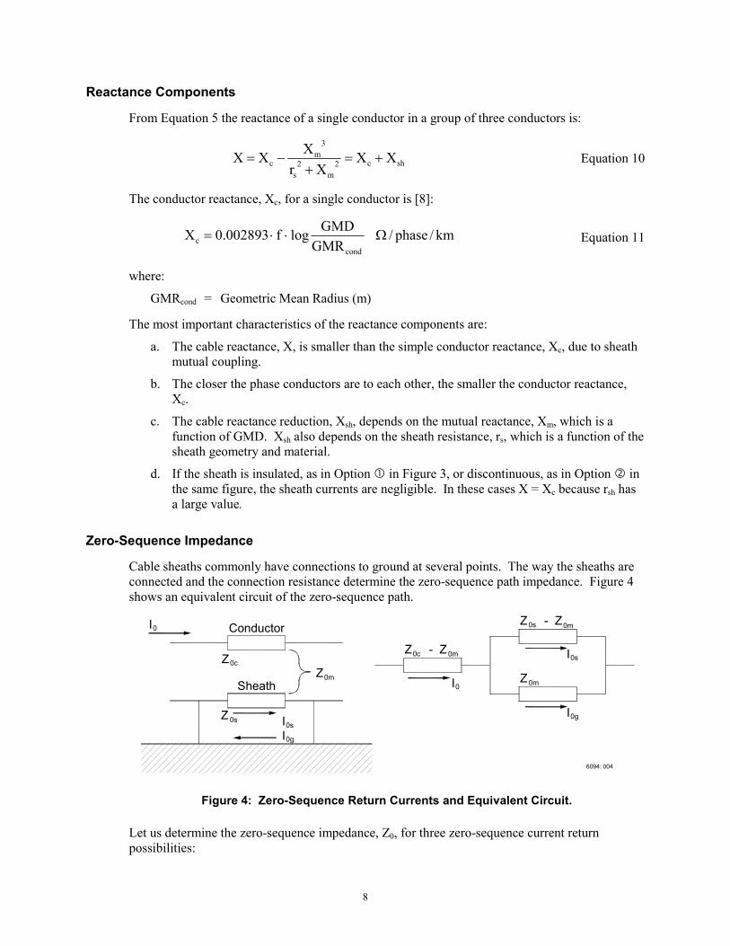
Cable sheaths commonly have connections to ground at several points. The way the sheaths are connected and the connection resistance determine the zero-sequence path impedance. Figure 4 shows an equivalent circuit of the zero-sequence path.
0gI
0sI
I0
0gII0s
6094: 004
0mZ
0m0sZ - Z
0mZ - Z0c
Z0m
0
Z0c
0s
I
Z
Sheath
Conductor
Figure 4: Zero-Sequence Return Currents and Equivalent Circuit.
Let us determine the zero-sequence impedance, Z0, for three zero-sequence current return possibilities:

9
1. Current return in the sheath only; I0s:
m0s0m0c00 ZZZZZ −+−= Equation 12
m0s0c00 Z2ZZZ −+= Equation 13
2. Current return in the ground only; I0g:
c0m0m0c00 ZZZZZ =+−= Equation 14
3. Current return in sheath and ground in parallel; I0s and I0g:
( )s0
m0m0s0m0c00 Z
ZZZZZZ ⋅−+−= Equation 15
s0
m0c00 Z
ZZZ 2
−= Equation 16
where:
Z0c = Zero-sequence conductor impedance (Ω)
Z0s = Zero-sequence sheath impedance (Ω)
Z0m = Zero-sequence mutual impedance (Ω)
The most important characteristics of zero-sequence impedance are:
a. The impedance depends on the method of bonding and grounding the cable sheath.
b. Its angle may vary from small angles (return current in sheath only) to angles close to the cable Z0c angle (return current in ground only).
c. The presence of parallel paths (cables, ground conductors) and the earth’s resistivity must be considered in determining the zero-sequence impedance.
d. In the case of magnetic ducts, zero-sequence impedance varies with the zero-sequence current.
Based on the characteristics listed above, zero-sequence quantities are not suitable for cable protection. Similarly, this same reasoning reveals the difficulty in applying ground distance protection to cables.
Shunt Capacitive Reactance
The capacitance, C, between an insulated conductor within a concentric sheath and the sheath itself is [4]:
km/F
rrlog
024127.0C
di
do
R µε⋅
= Equation 17

10
where:
εR = Relative permittivity of the insulation material
rdo = Inside radius of the sheath or outside radius of the insulation, if shielding tape is used (m)
rdi = Radius of the conductor (m)
If the sheath is grounded, Equation 17 gives the capacitance to ground.
6094: 005
dir
dor
dir
rdo
Figure 5: Capacitance of Shielded Conductors.
The positive-, negative-, and zero-sequence shunt capacitances for single conductors with metallic sheaths are all equal. This is also true for three conductor-shielded cables having round conductors and their own shielding layer. Figure 5 shows the cross sections of a single-conductor and a three-conductor cable. Three conductor-belted cables without conductor shielding have smaller zero-sequence capacitance than positive- and negative-sequence capacitances.
The most important characteristics of the shunt capacitive reactance are:
a. For a single conductor with a metallic sheath, the positive-, negative-, and zero-sequence capacitances are the same as the capacitance of one of the conductors to its sheath (C1 = C2 = C0).
b. Cable capacitance depends mostly on single-conductor geometry.
c. There is no relation between S (distance between single conductors) and the cable shunt capacitance.
d. As the dielectric strength of insulation increases (new materials or process), cable capacitance increases while the required thickness of insulation decreases.
e. The zero-sequence, x0, positive-sequence, x1, and negative-sequence, x2, shunt
capacitance reactances are equal to 0C
1⋅ω
, 1C
1⋅ω
, and 2C
1⋅ω
respectively. C0, C1,
and C2 are the zero-, positive-, and negative-sequence capacitances per unit length. Equation 18 converts capacitance-per-kilometer to total ohms-per-phase reactance, where l is the length in kilometers:

11
012
012C012C Cf2
1xX⋅⋅π⋅⋅
==ll
Equation 18
Submarine Cable
Submarine cables are located at a considerable depth from surface level; thus the return current path consists not only of sheath and ground but also of seawater.
The current distribution among paths varies inversely to the path resistivities. Because seawater resistivity varies from 0.01 to 0.000025 times ground resistivity, practically all the return current goes through seawater. For this reason, we also need to consider seawater resistivity when calculating the cable zero-sequence impedance.
Playa del Carmen – Chankanaab Cable Parameters
The power cable in our application connects Playa del Carmen Substation (PCA) on the Yucatan Peninsula mainland with Chankanaab II (CHS) Substation at Cozumel Island. Connection is through two 34.5 kV circuits (CI1, CI2). Each circuit consists of three single-phase conductors, and each circuit has three sections. Table 1 lists the length and type of each section. Appendix 1 includes cable geometry and configuration.
Table 1: Circuit Sections
Section From To Length (m) Type
1 Playa del Carmen Substation (PCA)
Sea Shore at Playa del Carmen 5,500 Underground
2 Sea Shore at Playa del Carmen
Sea Shore at Cozumel Island 18,000 Submarine
3 Sea Shore at Cozumel Island
Chankanaab II (CHS) Substation 500 Underground
Calculate the cable sequence impedances by completing the following steps:
a. Obtain cable impedance and admittance matrices for each cable section.
b. Obtain per-phase PI equivalent circuits.
c. Calculate per-phase ABCD constant networks for each cable section [6].
d. Obtain the series equivalent of the three sections.
e. Obtain the PI equivalent circuit of the three sections.
f. Calculate sequence impedance and admittance from the phase impedance and admittance matrices, ZABC and YABC.
Equation 19 and Equation 20 transform the phase matrices to sequence matrices.
TZTZ ABC1
012 ⋅⋅= − Equation 19
TYTY ABC1
012 ⋅⋅= − Equation 20

12
where:
T = Symmetrical Component Transformation [5].
Table 2 shows the total cable sequence impedances and admittances that include the three cable sections.
Table 2: Cable Equivalent Sequence Impedances and Admittances
Sequence Impedance (Ω) Admittance (S)
Zero °∠= 2439.13Z0 °∠= 9.890019.0Y0
Positive °∠= 5456.10Z1 °∠= 9.890019.0Y1
Negative °∠= 5456.10Z2 °∠= 9.890019.0Y2
NEGATIVE SEQUENCE DIRECTIONAL ELEMENT
Negative-Sequence Impedance Measurement for Forward and Reverse Faults
We can measure the negative-sequence system impedance using the negative-sequence voltage and current, V2 and I2, at the relay location for a given system. We call this impedance Z2Measured. Figure 6 shows a two-source system and the negative-sequence network for ground faults.
6094: 006
S R
2
IR2S2I 2V
RS RESE
2
ZZL2 R2S2Z
I
FaultForward
FaultReverse
Z
RZLSZ Z
Figure 6: Negative-Sequence Impedance Measurement for Forward and Reverse Faults.
Table 3 shows the negative-sequence impedance measurement for forward and reverse single-line-to-ground, SLG, faults.

13
Table 3: Negative-Sequence Impedance Measurement for Forward and Reverse Faults.
Condition V2 I2 Z2Measured
SLG Forward Fault -IS2·ZS2 IS2 -Zs2
SLG Reverse Fault -IR2·(ZR2+ZL2) -IR2 ZR2 +ZL2
where:
ZS2 = Negative-sequence source impedance at S (Ω)
ZR2 = Negative-sequence source impedance at R (Ω)
ZL2 = Negative-sequence line impedance (Ω)
Schweitzer and Roberts [10] describe a negative-sequence directional element that measures the negative-sequence impedance, Z2, and compares the result against forward and reverse thresholds to make a fault direction declaration. The directional element uses Equation 21 for Z2 measurement.
( )[ ]2
2
*22
I1IVRe2Z θ∠⋅⋅
= Equation 21
where:
Z2Measured = Measured negative-sequence impedance (Ω)
∠θ = Negative-sequence line impedance angle (degrees)
The negative-sequence directional element declares a forward fault condition if Z2Measured is less than the forward threshold, Z2F. The element declares a reverse fault condition if Z2Measured is greater than the reverse threshold, Z2R. Z2F must be less than Z2R to avoid any overlap between the forward and reverse regions.
Z2Measured = -ZS2 for forward faults and Z2Measured = Z2L + Z2R for reverse faults. The impedance measurement difference for forward and reverse faults is: ZS2 + Z2L + Z2R. We need to set the Z2F and Z2R thresholds between the forward and reverse Z2 measurements. If we assume infinite sources, Z2L is the impedance measurement difference between forward and reverse faults.
TX = Transmitter; RX = Receiver 6094: 007
ESZS
S ZLR ZR
ER
TXRX
67RRXTX
67S
Figure 7: Negative-Sequence Directional Elements, 67, at Both Cable Ends for
Unbalanced Fault Protection.

14
We can implement a directional comparison scheme to detect unbalanced cable faults with these directional elements at both cable ends. Figure 7 shows these directional elements, 67S and 67R, in a POTT scheme implemented using relay-to-relay communications [11].
Table 4 shows the negative-sequence impedance measurement of both directional elements for single line-to-ground, SLG, faults.
Table 4: Negative-Sequence Impedance Measurements at Both Cable Ends
SLG Fault Location Z2Measurement at S Z2Measurement at R
S ZL2 + ZR2 -ZR2 in-line -ZS2 -ZR2
R -ZS2 ZL2 + ZS2
The impedance measurement differences between forward and reverse faults at both cable ends are:
Directional Element at S:
Z2 ( ) 2R2L2S2S2R2L ZZZZZZ ++=−−+= Equation 22
Directional Element at R:
( ) 2S2L2R2R2S2L ZZZZZZ2Z ++=−−+= Equation 23
We set Z2F = ZL2/2 and Z2R = Z2F + 0.1, at both ends of the cable; with these settings, the directional elements make the correct fault direction declaration without forward and reverse region overlap.
V2
I2Z2
Enable Z2F
Z2RReverse Fault
Forward Fault
6094: 008
_+
_+
Figure 8: Negative-Sequence Directional Element With Forward and Reverse Thresholds
for Fault Direction Declaration [12].

15
Z2 IMPEDANCE LOCUS IN CABLE APPLICATIONS
Negative-Sequence Impedance Locus Considering Cable Admittance
The line model in the previous section only included the line series impedance, ZL. This model is appropriate for overhead line applications where line admittance is negligible because its relative value is small compared to the series impedance of the line. This model is not valid for cable applications, because of the following facts:
a. As phase conductors get closer to each other, the line series impedance gets smaller.
b. As the distance between the phase conductor and the sheath decreases, the cable capacitance increases. As capacitance increases, shunt capacitive reactance decreases.
c. Series impedance is proportional to cable length; shunt capacitance reactance is inversely proportional to cable length.
Let us analyze the effect of adding the cable admittance to the cable model in the directional element Z2 measurement.
Figure 9 shows a negative-sequence network for a two-source system with a cable interconnection. The cable model includes shunt capacitive admittance at both cable ends.
6094:009
L2
2Y
2YL2
RE
IR2
RRSSE
ZR
2
L2Z
2
ForwardFault
SS2Z
V 2S2I
Z
ReverseFault
I
ZZS L Z
R2
Figure 9: Two-Source System With a Cable Interconnection. The Negative-Sequence
Network Includes the Cable Admittance.
For a forward fault, V2 =-IS2 ⋅ ZS2 and I2 = IS2,
then:
2S2S
2S2SForwardMeasured Z
IZI2Z −=⋅−
= Equation 24

16
For a reverse fault Z2Measured Reverse is expressed in terms of the network elements as follows:
2R2L2
2L2L2L2R2L
2R2R2L2L2LverseReMeasured ZZYZY2ZY44
Z4ZZY2Z42Z⋅⋅+⋅⋅+⋅⋅+
⋅+⋅⋅⋅+⋅= Equation 25
where:
YL2 = Negative-sequence cable admittance (S)
Figure 10 shows the negative-sequence impedance locus in the negative-sequence impedance plane for a reverse fault for different YL2 values while all other impedances are constant. When the admittance is zero, the Z2 measurement is at point B; this point corresponds to the simplified series impedance model case. As the admittance increases, the measurement point moves upper to the right and the distance to the origin increases. We will have a point between B and C for different cable types.
6094:010
Forward Faults
BC
A
Reverse Faults
X2
R2
-Z2
ZR2 + ZL2
Figure 10: Negative-Sequence Impedance Locus for Reverse and Forward Faults in
Cable Application.
To properly apply the negative-sequence directional element, the forward and reverse fault regions should not overlap.
Z2 Locus in Submarine Cable Applications
Figure 11 shows the negative-sequence impedance locus for a submarine cable that has the same characteristics and configuration as the one in Section 2 of our application. The figure shows two traces for reverse SLG faults: one of the traces corresponds to the impedance locus without considering the cable capacitance in the line model; the other one includes it. Each point in the graph corresponds to different cable lengths, 1, 2, 4, 8, 16, 32, 64, and 128 km. We start to notice the cable capacitance effect on the impedance locus for distances of 32 km and beyond. The angle of the negative-sequence impedance varies from 78º to 39º. The first angle corresponds to 1 km and the second one to 128 km.

17
80
70
60
50
40
30
20
10
0
X2 (Ω
)
R2 (Ω)
0 10 20 30 40 50 60 70 80
CapacitanceNot Included
CapacitanceIncluded
Figure 11: Negative-Sequence Impedance Locus for Reverse Faults in Submarine Cable Application.
CONCLUSIONS 1. Cable zero-sequence impedance depends on the current return paths, while the negative-
sequence impedance does not. For this reason, negative-sequence quantities are more suitable than zero-sequence quantities for cable protection.
2. Negative-sequence directional elements, with the aid of communications, provide reliable and sensitive cable protection against unbalanced faults.
3. The cable negative-sequence admittance modifies the Z2 measurement for reverse faults. This admittance must be included in the cable model to properly determine the negative-sequence directional element relay setting.
4. The negative-sequence impedance measurement defines forward and reverse regions in the negative-sequence impedance plane that do not overlap.
5. Distance elements require special setting ranges to properly compensate for the cable zero-sequence impedance.

18
REFERENCES [1] IEEE Standards Board, “IEEE Recommended Practice for Protection and Coordination of
Industrial and Commercial Power Systems,” the Institute of Electric and Electronics Engineers, Inc., 1986.
[2] Working Group D12 of the Line Protection Subcommittee, PSRC, “Protective Relaying Considerations for Transmission Lines with High Voltage AC Cables,” IEEE Transactions on Power Delivery, Vol. 12, No. 1, January 1997.
[3] Roberts, J., Schweitzer, E. O. III, Arora, R., and Poggi, E., “Limits to the Sensitivity of Ground Directional and Distance Protection,” 50th Annual Georgia Tech Protective Relaying Conference, Atlanta, GA, May 1996.
[4] E. Clarke, “Circuit Analysis of A-C Power Systems Volume II,” General Electric Company, 1950.
[5] C. F. Wagner and R. D. Evans, “Symmetrical Components,” McGraw-Hill Book Company, Inc., 1933.
[6] Central Station Engineers, “Electrical Transmission and Distribution Reference Book,” 4th Edition, Westinghouse Electric Corporation, 1964.
[7] J. Roberts and A. Guzmán, “Directional Element Design and Evaluation,” 21st Annual Western Protective Relay Conference, Spokane, WA, October 1994.
[8] J. Lewis Blackburn, “Symmetrical Components for Power Systems Engineering,” Marcel Dekker Inc., 1993.
[9] Sumitomo Electric Industries, LTD, “Development of Optical Fibers Incorporated Single-Core Submarine Power Cable,” Sumitomo Electrical Review, 1994.
[10] E. O. Schweitzer III and J. Roberts, “Distance Relay Element Design,” 19th Annual Western
Protective Relay Conference, Spokane, WA, October 1992. [11] Behrendt, K. C. “Relay-to-Relay Digital Logic Communication for Line Protection,
Monitoring, and Control,” 23rd Annual Western Protective Relay Conference, Spokane, WA, October 1996.
[12] Armando Guzmán, J. Roberts, and D. Hou, “New Ground Directional Elements Operate Reliably for Changing System Conditions,” 23rd Annual Western Protective Relay Conference, Spokane, WA, October 1996.

19
BIOGRAPHIES Jesús Vargas received his BSEE with honors from Guadalajara Autonomous University (UAG), Mexico, in 1986. He served as a relay protection engineer from 1986 to 1996 at the Federal Electricity Commission mainly dedicated to fault analysis, new technology evaluation, and commissioning. In 1996 he joined INELAP as a director of the protective relaying division. INELAP provides design, consultant, and support services in protective relaying, control, integration and automation for both utility and industry. He has been a lecturer at UAG in power system protection. He is a member of the IEEE and served as IEEE official for the Guadalajara, Jal. Mexico section. Armando Guzmán received his BSEE with honors from Guadalajara Autonomous University (UAG), Mexico, in 1979. He received a diploma in fiber-optics engineering from Monterrey Institute of Technology and Advanced Studies (ITESM), Mexico, in 1990. He served as regional supervisor of the Protection Department in the Western Transmission Region of the Federal Electricity Commission (the electrical utility company of Mexico) for 13 years. He lectured at UAG in power system protection. Since 1993 he has been with Schweitzer Engineering Laboratories, Pullman, Washington, where he is presently a research engineer. He is a member of IEEE and has authored and coauthored several technical papers. Jorge Robles received his BSEE from the National Polytechnic Institute (IPN), Mexico, in 1976. He joined the Federal Electricity Commission in 1978 as a protective relaying engineer. Since 1988 he has been chief of the Distribution Substations Office, in charge of the national distribution and subtransmission networks’ protective relaying systems. He is an IEEE member and a member of the protective relaying subcommittee of Mexico’s IEEE section and has authored and coauthored technical papers.

20
APPENDIX 1: CABLE GEOMETRY AND CONFIGURATION
Cable Sections 1 and 3
Underground Cable Voltage: 34.5 kV Conductor Material: Copper Cu
Conductor Area: 400 mm2
Insulation: XLPE Section 1 Length: 5,500 m Section 3 Length: 500 m
Ampacity: 566 A
Table 5: Cable Geometry and Material Characteristics of Sections 1 and 3
Section Material Thickness
(mm)
Resistivity
(Ω ⋅ m)
Permeability
µR
Permittivity
R
1. Conductor Copper 23.5 1.72 x 10⁻⁸ 1 -
2. Insulator 1 XLPE 10.25 - 1 2.35
3. Sheath Copper 0.2 1.72 x 10⁻⁸ 1 -
4. Insulator 2 PVC 4 - 1 4.55
rc = 11.75 mm ∆1 = 10.25 mm
ri1 = 22 mm ∆2 = 0.2 mm
ri2 = 22.2 mm ∆3 = 4 mm
r0 = 26.2 mm
6094: 011
Not to Scale
3211
2
3
4
r0 ri2
ri1
Cr
Cable Transverse Section
Meters
Cable Configuration
0.250.250.250.250.25
2.00 Meters
Figure 12: Cable Geometry and Configuration of Sections 1 and 3.

21
Cable Section 2 Submarine Cable Voltage: 34.5 kV Conductor Material: Copper Cu
Conductor Area: 300 mm2
Insulation: XLPE Sheath: Lead
Length: 18,000 m Ampacity: 500 A Table 6: Cable Geometry and Material Characteristics of Section 2
Section Material Thickness
(mm)
Resistivity
(Ω ⋅ m)
Permeability
µR
Permittivity
R
1. Conductor Copper 21.6 1.72 x 10⁻⁸ 1 -
2. Insulator 1 XLPE 9.56 - 1 2.35
3. Sheath Lead 2.20 20.10-8 1 -
4. Insulator 2 Polyethylene 9.1 - 1 2.35
5. Armor Steel 10.26 9.70 x 10⁻⁸ 300 -
6. Insulator 3 PVC 3.6 - 1 4.55
6094: 012
Not to Scale
1 rC
L = 17,800 Meters
L F = 17,918.93 Meters
Playa delCozumelCarmen
MetersDeep
Kilometers
0
500
400
100
200
300.
0
100
200
300.
500
400
1817161514131211109876543210
5432
6543
12
r0
ri4
ri3ri2
ri1
Cr
Sea
2020202020 Meters
Cable Configuration
300.00 Meters
Cable Transverse Section
Figure 13: Cable Geometry and Configuration of Section 2.

22
rc = 10.8 mm ∆1 = 9.56 mm
ri1 = 20.36 mm ∆2 = 2.20 mm
ri2 = 22.56 mm ∆3 = 9.1 mm
ri3 = 31.66 mm ∆4 = 10.26 mm
ri4 = 41.92 mm ∆5 = 3.6 mm
r0 = 45.52 mm
Copyright © 1999, 2000 INELAP-PQE., Comision Federal de Electricidad, and Schweitzer Engineering Laboratories, Inc.
(All rights reserved) 20000117 • TP6094-01