· under nda 3 table of contents introduction...
TRANSCRIPT

Interoperability Event
Test Plan
Version 2.02014-02-07
UNDER NDA
EANTC AG

Copyright (C) 2014 EANTC European Advanced Networking Test Center Aktiengesellschaft
This document is copyrighted by EANTC AG. It may not, in whole or in part, be reproduced, transmitted by any means or stored in any web site or electronic retrieval system without the prior written permission of EANTC AG. EANTC AG grants the receiving party of this test plan a non-transferable right to use this document for internal purposes with regards to projects with EANTC. All copies must retain and reproduce this copyright notice and all other copyright notices contained within the original material.
Salzufer 14, Building 3, Entrance D10587 Berlin Germany
Tel. +49. (0)30. 318 05 95–0 Fax +49. (0)30. 318 05 95–10 E-Mail [email protected] http://www.eantc.de/

Table of Contents
Introduction ................................................................................................. 4Interoperability Testing Goals ..................................................................... 5Demonstration Concept ............................................................................. 6Demonstration Use Cases .......................................................................... 6Demonstration: Data Center Workload Mobility ........................................... 7Demonstration: Video Delivery Quality Assurance with SDN .......................... 9Contacts ................................................................................................ 11Disclaimer .............................................................................................. 11Version History ....................................................................................... 11
Software Defined Networking ...................................................................... 12OpenFlow: Rate Limiting........................................................................... 12OpenFlow: Bandwidth on Demand/Bandwidth Guarantee ........................... 15OpenFlow: Interworking with non-OF MPLS Switches ................................... 18OpenFlow: 1:1 Protection......................................................................... 20Centralized Controller as Path Computation Client ....................................... 23
Data Center Interconnect Transport ............................................................... 25VXLAN Transport ..................................................................................... 26Service Activation .................................................................................... 28Two-Way Active Measurement using TWAMP.............................................. 35
Packet Clock Synchronization ...................................................................... 38Precision Time Protocol as GPS Backup ...................................................... 38Phase/Time Hold-Over Performance........................................................... 42Precision Time Protocol: Master Clock Scalability ......................................... 45Precision Time Protocol: Boundary Clock Noise Generation (Time/Phase)....... 49PTP over Adaptive Modulation Microwave System ....................................... 53Precision Time Protocol: Transparent Clock Scalability .................................. 58
UNDER NDA 3

Introduction
This document describes the proposed topics, use cases and test methodolo-gies that will be the basis for the EANTC Interoperability event for MPLS and SDN World Congress, V6 World Congress and NFV & SDN Summit taking place in Paris, March 2014.
The document is edited by EANTC who retains final control of the interoper-ability event‘s technical direction. This version of the test plan is the final version of the test plan, a result of the discussion with the interested vendors and based on their interest and proposals.
There are two main parts to this EANTC interoperability event:• Closed door hot staging: A fully immersive test event taking place in
EANTC’s lab in Berlin under NDA• Public showcase: Results from the hot staging are showcased and
demonstrated live in Paris during the MPLS and SDN World Congress, V6 World Congress and NFV & SDN Summit.
Given the variety of test topics in different technology areas, EANTC suggests a different focus for each week.
For the first week starting on February 10, we propose:• Software Defined Networking• Data Center Interconnect Transport• Clock Synchronization
For the second week starting on February 17, we propose:• Service activation and TWAMP• Demonstration Use Cases (see below)
In the second week we also plan to integrate the demonstration network, and verify the demos for the showcase in Paris.
UNDER NDA 4

Interoperability Testing Goals
This section describes the test cases goals for the event:• Software Defined Networking
This area will focus on OpenFlow and Path Computation Element (PCE) protocols. We intend to test interoperability between OpenFlow (OF) controllers and OF forwarders for data and control protocol flows as well as Path Computation Elements (PCEs) and Path Computation Clients (PCC). The test scenario include rate-limiting, on-demand bandwidth management and bandwidth guarantees, interoperability between OpenFlow and non-OpenFlow MPLS devices, path protection and interoperability between PCE and OpenFlow and management of LSPs via PCE. Targeted Equipment: OF Controller, OF Forwarder, OF FlowVisor, PCE client, PCE controller
• Data Center Interconnection Transport This area will focus on the technologies that enable and verify cloud delivery services. We intend to test interoperability of Virtual Extensible Local Area Network (VXLAN) as well as service activation based on Y.1564 and two-way active measurements using TWAMP. Targeted Equipment: VXLAN Tunnel End Point (VTEP), Service Activa-tion Endpoints, TWAMP Endpoints
• Clock Synchronization We are eager to progress with our past successful tests for Clock Synchronization. In the upcoming event we aim to test interoperability for IEEE 1588-2008/PTP protocol, verifying synchronization accuracy (frequency and phase) for boundary, transparent, and ordinary clocks. We intend to focus on the following topics: GPS reference with PTP as backup, holdover test for phase/time of day, grandmaster and boundary clocks client scalability, transparent clock client scalability, noise transfer of boundary clocks and PTP over adaptive modulation microwave systems. Targeted Equipment: PTP grandmaster clock, PTP boundary clock, PTP ordinary clock, SyncE/PTP hybrid clock.
UNDER NDA 5

Demonstration Concept
The demonstration concept in this event is focused on cloud delivery and orchestration. At the end of hot-staging we will combine the successful results into a single fully operational demonstration network. With this network we will emulate a service provider design in which we will be show-casing complex completed and successful use cases (see below).
We welcome vendors willing to integrate OpenDaylight into the test cases and demonstration network as the orchestration module — it is however not a requirement.
The following figure provides a concept of the demonstration network.
FIGURE 1. Demonstration Network Concept
Wide Area Network (WAN)
Physical Infrastructure Virtual Infrastructure
Tenant A
Tenant B
Tenant A
Tenant B
Physical Infrastructure Virtual Infrastructure
Physical & Virtual Network DeviceMulti-Tenant Cloud
OpenDayLight/
Network Apps & Orchestration
SDN Controller Southbound Interfaces
Other Orchestration
vPE
Data Center Server
OpenFlow, PCEP, NETCONF, SNMP, LISP, BGP-LS
vCE
vCE
vCE
vCE
IP/MPLS, MPLS-TP
Demonstration Use Cases
The following use cases are planned for demonstration over the integrated network:
• Data Center Workload Mobility — we will emulate a large virtual machine (VM) cluster and VM mobility within the cluster. We will validate the network ability to support dynamic VM workload mobility and measure VM convergence time. To participate in this demo, the under-lying core network devices must pass an appropriate test case from the SDN or transport sections.
• Video Delivery Quality Assurance with SDN— we will setup a streaming video application between a client and a server. We will generate load on the network causing a degradation in video quality. Afterward we will use OpenFlow to provision QoS through the network guaranteeing the bandwidth for the application, causing the quality to improve. To participate in this demo, vendors must pass test case “OpenFlow:
UNDER NDA 6

Bandwidth on Demand/Bandwidth Guarantee”, as described in the SDN section.
Demonstration: Data Center Workload Mobility
DEMONSTRATION PURPOSE
In this demonstration we will use a data center emulator to showcase work-load mobility and disaster recovery in a data center (DC).
In order to support this demonstration, the following component will be used:• Provider Edge Router – located at the edge of the data center and
provide IP/MPLS VPN connectivity to the remote data center.• Data Center Emulator – provide a virtual infrastructure emulation.
Emulates a large number of virtualized server hosts running on top of various hypervisors. Provisions virtual machines (VMs) with various profiles and emulates VM manager to start, stop, deploy, tear down and migrate VMs.
• Traffic Generator – generate bidirectional traffic between external client and internal emulated servers in the data center as well as generate traffic between different data centers across the Data Center Interconnect (DCI) network. The traffic generators will be used to measure the conver-gence time during VM migration between data centers.
• Physical and Virtual Infrastructure – Provide the network connectivity as well as the interface between the external clients and the virtual compo-nents. This includes virtual switch (vSwitch), DCI LAN extension, Layer 3 extension and path optimization.
REQUIREMENTS The following table shows the requirements per components for this demon-stration.
TABLE 1. Requirements — Data Center Workload Mobility
Components Requirement
VM Manager – Orchestrate the life cycle of VMs in the data centers.
Data Center Emulator – Inter-DC VM migration support.– Multiple tenant support.– vSwitch support.– North-bound API for an orchestrator.
vSwitch – Provide virtual switching facilities for VMs. Enables creating logical bridges between VMs and/or physical infrastructure.
DCI – LAN Extension – Provide a layer 2 connection across data centers
Layer 3 Extension – Provide routed connectivity between data centers. DCI network must be able to route VM traffic between tenant network across both data centers.
Path Optimization – Optimize traffic flows between external clients and internal servers following VM migration between data centers, enabling efficient traffic flow.
UNDER NDA 7

DEMONSTRATION TOPOLOGY
The following diagram depicts the suggested demonstration topology.
FIGURE 2. Demonstration Topology — Data Center Workload Mobility
IP/MPLS, MPLS-TP
Multi-Tenant Cloud
Other Orchestration
IP/MPLS, MPLS-TP
VM
VM VM
VMVM
VM
VM
VM VM
VMVM
VM
Virtual Infrastructure
Tenant B
Virtual Infrastructure
VM Manager
VM Migration
VM
VM
Tenant B
Tenant A Tenant A
VM Orchestration
Tenant A Traffic
Tenant B Traffic
Traffic Generator
External Client Traffic
(External clients)
Physical/Virtual Network Device
DEMONSTRATION PROCEDURE
1. Construct two data centers (DC–A and DC–B).
2. Create two tenants in each data center (Tenant A and Tenant B).
3. Instantiate 100 VMs in each tenant.
4. Create logical bridge for each tenant in the vSwitch.
5. Attach VMs to the vSwitch.
6. Create a Data Center Interconnect (DCI) using IP/MPLS, MPLS-TP or VXLAN.
7. Instantiate a tunnel between VMs in the same tenant across the data centers.
8. Generate VM to VM bidirectional traffic at an aggregate rate of 10,000 packets/seconds across all VMs between both data centers.
9. Generate bidirectional traffic from the traffic generator (emulating an external client) to the VMs that will be migrated from DC–A to DC–B at aggregate rate of 1,000 packets/seconds.
10. While transmitting VM to VM traffic, initiate VM migration between both data center.
11. Measure VM migration convergence time and latency.
UNDER NDA 8

Demonstration: Video Delivery Quality Assurance with SDN
DEMONSTRATION PURPOSE
In this demonstration, we intend to show how an SDN network capabilities can be leveraged to ensure video delivery with quality assurance.
To support this demonstration, we will have the following components:• SDN Orchestrator – Provide the human-to-network interface and manage
the life cycle of the services. Interfaces to the network through the north-bound API of the OpenFlow controllers.
• OpenFlow Controller – Provide the control plane of the network via OpenFlow protocol, acts on instructions from the SDN orchestrator.
• OpenFlow Switches – Handle the data plane of the network according to the OpenFlow controller’s instructions.
• Video Content Server – Provide the video content to the video clients.• Emulated Video Clients – Consume video content and measure quality of
experience (estimation of MOS).• Non-emulated Video Clients – Consume video content and provide visual
indication of the quality.• Traffic Generators – Load the network with traffic to induce quality degra-
dation in the video streams.
REQUIREMENTS The following table shows the requirements per components for this demon-stration.
TABLE 2. Requirements — Video Delivery Quality Assurance with SDN
Component Requirement
SDN Orchestrator – South-bound API capable of managing the OpenFlow controllers.Specific API shall be agreed between SDN orchestrator and OpenFlow controller vendors.
OpenFlow Controller – North-bound API providing functions to support traffic MPLS and TE configura-tion (see also OpenFlow switch requirements below).Specific API shall be agreed between SDN orchestrator and OpenFlow controller vendors.
OpenFlow Controller,OpenFlow Switch
– Minimum OpenFlow version support: 1.3Specific requirements:– Basic IP forwarding match/actions (match on IP prefix, set destination MAC and send to port).– Basic MPLS ingress (match on IP prefix, push MPLS label, set destination MAC, send to port).– Basic MPLS transit (match on MPLS label, set MPLS label, set destination MAC, send to port).– Basic MPLS egress (match on MPLS label, set destination MAC, send to port).– Match on destination MAC or destination IP, send to controller port.– Flow/Port statistics.
UNDER NDA 9

DEMONSTRATION TOPOLOGY
The following diagram depicts the suggested demonstration topology.
FIGURE 3. Demonstration Topology — Video Delivery Quality Assurance with SDN
Video Server 1
Video Client 2 Video Client 1
Video Server 2
TrafficGenerator 1
TrafficGenerator 2
DataPlane
ControlPlane
OpenFlow
OpenFlowOpenFlow
SDN Orchestrator
OF Controller
Switch 3
witch 1 Switch 2
Data link
Video Stream 2
OpenFlow/SDN APIs
Background Traffic
Video Stream 1
DEMONSTRATION PROCEDURE
1. Session between SDN orchestrator and OpenFlow controller(s) should be established, as well as the sessions between the OpenFlow controller(s) and the OpenFlow switches. Video server shall be online and ready for requests. The clients and traffic generators shall be connected to the network, but should not be started.
2. Start two video streams from the video clients (one from the emulated client, one from the non-emulated client). Video quality and MOS score should be highest possible according to the content served by the video server.
3. Start loading the network with traffic using the traffic generator. Increase the load until both MOS score and visual quality degrade to a noticeable level.
4. Initiate the optimization of the traffic flow from the SDN orchestrator. No configuration or instructions will be allowed on the OpenFlow controller(s) and switches. At least one of the video streams should be re-routed to run over OpenFlow switch 3.
5. MOS score and visual quality should match the observed quality in step 2. For maximum impact, SDN orchestrator should show the paths of the video streams through the network.
UNDER NDA 10

Contacts
EANTC AG, Salzufer 14, 10587 Berlin
Jambi Ganbar, Project Manager, [email protected],
+49.30.3180595-36
Disclaimer
This suite of tests has been developed to demonstrate the interoperability of various vendor equipment.
Successful completion of tests contained in this suite does not guarantee that the tested devices will operate with other devices. It does not guarantee conformance to any applicable specification. Successful completion also does not imply that a particular device will interoperate in every possible configuration or with every software revision available at the time of the test or in the future.
This test suite attempts to verify a certain minimum level of interoperability between devices of different vendors that increase the likelihood of reliable service in a multi-vendor environment. The tests are designed to help identify and isolate problem areas that should be addressed to ensure satisfactory functionality.
Version History
The following table tracks the version history and change descriptions:
TABLE 3. Version History Overview
Version Date Author Changes
1.0 Outline
2014-01-10 EANTC Outline version of the test plan with EANTC’s and vendor’s suggested test topics for review.
1.0 2014-01-24 EANTC First version of the test plan.
2.0 2014-02-07 EANTC Final version of the test plan.Test cases lacking vendor interest were removed. Test case numbering changed accordingly.
UNDER NDA 11

Software Defined Networking
1 Software Defined Networking
1.1 OpenFlow: Rate Limiting
PURPOSE Verify rate limiting is applied to a specific flow using OpenFlow.
DESCRIPTION Per-flow meters enable OpenFlow to implement various simple QoS opera-tions, such as DSCP remark, packet drop and can be combined with per-port queues to implement complex QoS frameworks.
A meter measures the rate of packets assigned to it and enables controlling the rate of those packets. Meters are attached directly to flow entries (as opposed to queues which are attached to ports).
TEST SETUP • Establish an OpenFlow channel between the OpenFlow controller and OpenFlow forwarder as shown in the figure below.
• Traffic generators emulate hosts and generate bidirectional traffic between them.
• Initial the flow table of all OF Switches are empty.
FIGURE 4. OpenFlow: Rate Limiting
OF Controller
Data link
OF channel
OF mgmt link
OF ForwarderTrafficGenerator 1
Mgmt network
Traffic FlowsTraffic
Generator 2
PARAMETERS Use the specific test case parameters defined in the table below.
UNDER NDA 12
Software Defined Networking
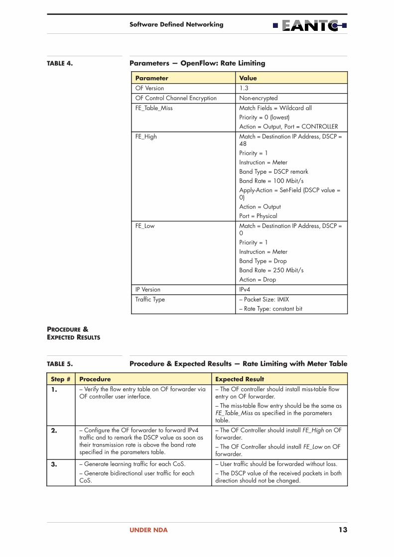
TABLE 4. Parameters — OpenFlow: Rate Limiting
Parameter Value
OF Version 1.3
OF Control Channel Encryption Non-encrypted
FE_Table_Miss Match Fields = Wildcard allPriority = 0 (lowest)Action = Output, Port = CONTROLLER
FE_High Match = Destination IP Address, DSCP = 48Priority = 1Instruction = MeterBand Type = DSCP remarkBand Rate = 100 Mbit/sApply-Action = Set-Field (DSCP value = 0)Action = OutputPort = Physical
FE_Low Match = Destination IP Address, DSCP = 0Priority = 1Instruction = MeterBand Type = DropBand Rate = 250 Mbit/sAction = Drop
IP Version IPv4
Traffic Type – Packet Size: IMIX– Rate Type: constant bit
PROCEDURE & EXPECTED RESULTS
TABLE 5. Procedure & Expected Results — Rate Limiting with Meter Table
Step # Procedure Expected Result
1. – Verify the flow entry table on OF forwarder via OF controller user interface.
– The OF controller should install miss-table flow entry on OF forwarder.– The miss-table flow entry should be the same as FE_Table_Miss as specified in the parameters table.
2. – Configure the OF forwarder to forward IPv4 traffic and to remark the DSCP value as soon as their transmission rate is above the band rate specified in the parameters table.
– The OF Controller should install FE_High on OF forwarder.– The OF Controller should install FE_Low on OF forwarder.
3. – Generate learning traffic for each CoS.– Generate bidirectional user traffic for each CoS.
– User traffic should be forwarded without loss.– The DSCP value of the received packets in both direction should not be changed.
UNDER NDA 13

Software Defined Networking
REFERENCES “OpenFlow Switch Specification”, OpenFlow version 1.3
4. – Generate bidirectional user traffic for High CoS at 2 times the band rate of FE_High.
– User traffic should be forwarded without loss.– Packets with DSCP value set to 48 should be received in both directions. Their information rate should match the band rate of FE_High.– Packets with DSCP value set to 0 should be received in both directions. Their information rate should match the band rate of FE_High.
5. – Generate bidirectional user traffic for Low CoS at 2 times the band rate of FE_Low.
– 50% packet loss is expected.– The DSCP value of the received packets in both direction should not be changed.– Packets with DSCP value set to 0 should be received in both directions. Their information rate should match the band rate of FE_Low.
Step # Procedure Expected Result
UNDER NDA 14

Software Defined Networking
1.2 OpenFlow: Bandwidth on Demand/Band-width Guarantee
PURPOSE Verify flow based dynamic bandwidth allocation and guarantee through the network using OpenFlow.
DESCRIPTION An OpenFlow controller may provide an interface to customer applications, handling requests for network service attributes modification to meet changing demands of the applications. Service attribute modifications may be made on-demand (i.e., fulfillment requested immediately) or scheduled (i.e., fulfillment requested at a designated time in the future).
TEST SETUP • Establish an OpenFlow channel between the OpenFlow controller and OpenFlow forwarder as shown in the figure below.
• Traffic generators emulated hosts and generate bidirectional traffic between them.
FIGURE 5. OpenFlow: Bandwidth on Demand/Bandwidth Guarantee
OF Controller
Data link
OF channel
OF mgmt link
OF ForwarderTrafficGenerator 1
Mgmt network
Traffic FlowsTraffic
Generator 2
PARAMETERS Use the specific test case parameters defined in the table below.
TABLE 6. Parameters – OpenFlow: Bandwidth on Demand/Bandwidth Guarantee
Parameter Value
OF Version 1.3
OF Control Channel Encryption Non-encrypted
FE_Table_Miss Match Fields = Wildcard all Priority = 0 (lowest)Action = Output, Port = CONTROLLER
FE_High Match = Destination IP, DSCP = 48Priority = 1Instruction = MeterBand Type = dropBand Rate = 100 Mbit/sAction = OutputPort = Physical
UNDER NDA 15

Software Defined Networking
PROCEDURE & EXPECTED RESULTS
TABLE 7. Procedure & Expected Results – OpenFlow: Bandwidth on Demand/Bandwidth Guarantee
FE_Low Match = Destination IP, DSCP= 0Priority = 1Instruction = MeterBand Type = dropBand Rate = 200 Mbit/sAction = OutputPort = Physical
Traffic Quota for Low CoS – 6 GBit (750 Mbyte)– After the quota was exceeded, rate throttled to 1 Mbit/s.– Quota is accounted bidirectionally in the same counter.
Additional Traffic Quota – 6 GBit (750 MByte)
Learning Traffic Rate 10 packet/second
Learning Traffic Duration 10 seconds
Test Traffic High – CoS Profile = High– Packet Size: IMIX– Rate Type: constant bit– Bit Rate A: 50 Mbit/s– Bit Rate B: 200 Mbit/s
Test Traffic Low – CoS Profile = Low– Packet Size: IMIX– Rate Type: constant bit– Bit Rate A: 100 Mbit/s– Bit Rate B: 400 Mbit/s
Parameter Value
Step # Procedure Expected Result
Part A: Test Setup Verification
1. – Verify the flow entry table on OF forwarder via OF controller user interface.
– The OF controller should install miss-table flow entry on OF forwarder.– The miss-table flow entry should be the same as FE_Table_Miss as specified in the parameters table.
2. – Generate bidirectional learning traffic.– Generate bidirectional user traffic as specified in the parameters table:
• Test traffic High, bit rate A• Test traffic Low, bit rate A
– The OF Controller should install FE_High and FE_Low flow entries on OF forwarder.– FE_High should contain policy entry to limit the traffic to 100 Mbit/s.– FE_Low should contain policy entry to limit the traffic to 250 Mbit/s.– No traffic loss expected for both traffic types.
UNDER NDA 16

Software Defined Networking
REFERENCES “OpenFlow Switch Specification”, OpenFlow version 1.3
3. – Increase the test traffic to bit rate B for both traffic types as specified in the parameters table.– Generate bidirectional user traffic as specified in the parameters table:
• Test traffic High, bit rate A• Test traffic Low, bit rate A
– 50% loss is expected for Test Traffic High.– 50% loss is expected for Test Traffic Low.
Part B: Self-service bandwidth increase with time limit
4. – Emulate self-service user action to double the provisioned traffic rate for Test Traffic High for a duration of 5 minutes.– Generate bidirectional learning traffic.– Generate bidirectional user traffic as specified in the parameters table:
• Test Traffic High, Bit Rate B• Test Traffic Low, Bit Rate B
– No traffic loss is expected for Test Traffic High for 5 minutes. After 5 minutes elapsed, 50% traffic loss is expected.– 50% loss is expected for Test Traffic Low.
Part C: Quota Top-up
5. – Configure quota for FE_Low as described in the “Traffic Quota for Low CoS” parameter.– Reset traffic meter to 0.
– Traffic meter should show the subscriber has consumed 0 bytes for FE_Low.
6. – Generate bidirectional learning traffic.– Generate bidirectional user traffic as specified in the parameters table:
• Test Traffic High, Bit Rate A• Test Traffic Low, Bit Rate A
– No traffic loss expected for both traffic types.– After 15 seconds exceeded, test traffic low traffic received rate is expected to be 1 Mbit/s in both directions.
7. – Stop traffic generation. – Traffic meter should show the subscriber has consumed 100% of its quota for FE_Low.
8. – Emulate self-service user action and provision additional quota for Test Traffic Low as described in the parameters.
– Traffic meter should show the subscriber has consumed 50% of its quota for FE_Low.
9. – Generate bidirectional learning traffic.– Generate bidirectional user traffic as specified in the parameters table:
• Test Traffic High, Bit Rate A• Test Traffic Low, Bit Rate A
– No traffic loss expected for both traffic types.– After 15 seconds exceeded, test traffic low traffic received rate is expected to be 1 Mbit/s in both directions.
Step # Procedure Expected Result
UNDER NDA 17

Software Defined Networking
1.3 OpenFlow: Interworking with non-OF MPLS Switches
PURPOSE Verify provisioning of IP/MPLS services between OpenFlow and non-Open-Flow devices.
DESCRIPTION The test verifies interworking between OF and non-OF devices in IP/MPLS network where RSVP-TE is used as LSP signalling protocol and OSPF-TE is used as routing protocol to distribute the link state and traffic engineering information between the nodes in the network.
OF Controller must support the following features: OSPF-TE and RSVP-TE implementation and TE LSP based on RSVP-TE (RFC 3209)
TEST SETUP • Establish an OpenFlow channel between the OpenFlow controller and OpenFlow forwarder as shown in the figure below.
• Establish OSPF and RSVP-TE session between OF and non-OF Switch.• Traffic generators emulated hosts and generate bidirectional traffic
between them.
FIGURE 6. OpenFlow: Interworking with non-OF MPLS Switches
OF Controller
OF Switch non-OF Switch
EmulatedCE 1
EmulatedCE 2
IP/MPLS
Data link
OpenFlow channel
OF mgmt link
RSVP-TE
Mgmt network
PARAMETERS Use the specific test case parameters defined in the table below.
TABLE 8. Parameters – OpenFlow: Interworking with non-OF MPLS Switches
Parameter Value
Min. Required OF Version 1.1
OF Control Channel Encryption Non-encrypted or encrypted
FE_Table_Miss Match Fields = Wildcard all Priority = 0 (lowest)Action = Discard
FE_OSPF Match = Destination IP AddressPriority = 1Action = OutputPort = CONTROLLER
FE_RSVP-TE Match = IPv4 protocolPriority = 1Action = OutputPort = CONTROLLER
UNDER NDA 18

Software Defined Networking
PROCEDURE & EXPECTED RESULTS
TABLE 9. Procedure & Expected Results – OpenFlow: Interworking with non-OF MPLS Switches Test Setup
Step # Procedure Expected Result
1. – Configure the default action on OF switch. – The OF controller should install “FE_Table_Miss” flow entry on OF switch.
2. – Generate “Test Traffic” between emulated CEs as specified in the parameters table.
– The traffic should not be forwarded by OF Switch.– The OF controller shows statistic for “FE_Table_Miss” flow entry on both switches. The number of dropped frames shown by the OF controller is the same as Tx counter on the “Emulated CEs”.
3. – Configure OF switch to forward the OSPF and RSVP-TE control traffic.
– The OF controller should install “FE_RSVP-TE” and “FE_OSPF” flow entries on OF switch.
4. – Configure and establish the OSPF and RSVP-TE session between OF switch and Non-OF switch.
– OSPF session should be up.– RSVP-TE session should be up.– Packet_in messages should be generated towards the OF controller with OSPF and RSVP-TE messages.– Packet_out messages should be generated by the OF controller with OSPF and RSVP-TE messages.
5. – Configure the OF switches to forward data traffic.
– The OF controller should install “FE_Data” flow entries on OF switch.
6. – Generate “Test Traffic” between emulated CEs as specified in the parameters table.
– No frame loss is expected.
REFERENCES “OpenFlow Switch Specification” - OpenFlow version 1.1
FE_Data Match = MPLS LabelPriority = 1Action = Push/Pop MPLS headerAction = OutputPort = Physical
Layer 2 Encapsulation IEEE 802.1q
Test Traffic – Packet Size: IMIX– Rate Type: constant bit– Packet Rate: 10,000 pps– Destination MAC Address: 00:00:00:0:00:02– Source MAC Address: 00:00:00:0:00:01
Parameter Value
UNDER NDA 19

Software Defined Networking
1.4 OpenFlow: 1:1 Protection
PURPOSE Verify 1:1 protection using OpenFlow, where the primary and secondary paths are predetermined and measure failover/recovery time.
DESCRIPTION This test case verifies that OpenFlow can be used to provide 1:1 protection and switch over the traffic from primary path to a secondary path following a failure. The OpenFlow switches monitors the status of the ports and inform the Open Flow controller when a change in state occurs.
OpenFlow version 1.2 specification introduced a new mechanism for protection switching. The mechanism is based on new group type called “fast-failure”. The group executes a list of action buckets and in a normal condition the first live action bucket in the list is executed. Each bucket is associated with a specific port and/or group.
This mechanism enables the OpenFlow switch to change the forwarding path without requiring a round trip communication to the OpenFlow controller.
TEST SETUP • Establish an OpenFlow channel between the OpenFlow controller and all four OpenFlow switches via the OF management links as shown in the figure below.
• Link failure will be emulated via physical disconnection.• The liveliness of the link is monitored with fast failure detection mecha-
nism.
FIGURE 7. OpenFlow: 1:1 ProtectionOF Controller
Data link
OF mgmt linkOF Switch1 OF Switch2
Mgmt network
Working PathTraffic
Generator 2 Protection PathTraffic
Generator 1
OF Switch3
OF Switch4
OF channel
PARAMETERS Use the specific test case parameters defined in the table below.
TABLE 10. Parameters – OpenFlow: 1:1 Protection
Parameter Possible Values
OF Version 1.2
OF Control Channel Encryption Non-encrypted
FE_Table_Miss Match Fields = Wildcard allPriority = 0 (lowest)Action = Output, Port = CONTROLLER
UNDER NDA 20

Software Defined Networking
PROCEDURE & EXPECTED RESULTS
The following table describes the Procedure & Expected Results in detail.
TABLE 11. Procedure & Expected Results – Link Resiliency
FE_Data Match = Ingress Port, Destination IP AddressPriority = 1Action = Output, Port = Physical port
GE_Data Match = Ingress Port, Destination IP AddressPriority = 1Action = GroupGroup Type = Fast Failover
Failure Trigger Type Loss of signal
Protection Type 1:1
Access Layer 2 Encapsulation IEEE 802.1q
IP Version IPv4
Learning Traffic Rate 10 packet/second
Learning Traffic Duration 10 seconds
Test Traffic – Packet Size: 128 Bytes– Rate Type: constant bit– Packet Rate: 10,000 pps– Direction: Unidirectional, from traffic generator 1 to traffic generator 2
Parameter Possible Values
Step # Procedure Expected Result
1. – Verify the flow entry table on all OF switches via OF controller user interface.
– The OF controller should install miss-table flow entry on all OF switches.– The miss-table flow entry should be the same as FE_Table_Miss as specified in the parameters table.
2. – Generate learning traffic between traffic gener-ator 1 and traffic generator 2 as specified in the parameters table.– Generate test traffic as specified in the parame-ters table.– Verify the flow entry table on OF switch 1, OF switch 2, and OF switch 3.
– No traffic loss is expected.– Traffic should be forwarded via OF switch 1 – OF switch 3 – OF switch 2.– The OF controller should install flow entry to route the traffic on OF switch 1.– The OF controller should install group entry with group type = fast failover on OF switch 1.
UNDER NDA 21

Software Defined Networking
REFERENCES “OpenFlow Switch Specification” - OpenFlow version 1.2
3. – Generate test traffic as specified in the parame-ters table.– While transmitting traffic, generate a link failure on link (OF switch 1 – OF switch 3) by discon-necting the link.– Measure the service interruption time seen in the network as a result of the link failure.– Wait 60 seconds to verify that the traffic is stable along the link (OF switch 1 – OF switch 4).
– The failure should be detected and the traffic should be switched via OF switch 1–OF switch 4– OF switch 2.– The service interruption time should be below 50 ms.
4. – Generate test traffic as specified in the parame-ters table.– While transmitting traffic, reconnect the link (OF switch 1 – OF switch 3).– Measure the service interruption time seen in the network as a result of the link reconnection.– Wait 60 seconds to verify that the traffic is stable along the link (OF switch 1 – OF switch 3).
– The failure removal should be detected and the traffic should be switch via OF switch 1–OF switch 3-OF switch 2.– The service interruption time should be below 50 ms.
Step # Procedure Expected Result
UNDER NDA 22

Software Defined Networking
1.5 Centralized Controller as Path Computa-tion Client
PURPOSE Verify that an OpenFlow controller can be used as Path Computation Client (PCC) to set up optimal TE-LSPs.
DESCRIPTION An application which runs at the OpenFlow controller can request setup of optimal paths. Path Computation Element (PCE) is a possible method to compute traffic engineering paths. PCC runs on OpenFlow controller and forward the client application path computation request to the PCE.
TEST SETUP • Establish an OpenFlow channel between the OpenFlow controller and OpenFlow-hybrid switches as shown in the figure below.
• Configure DUT4 to being a Path Computation Client (PCC).• Configure DUT2 to being a Path Computation Element (PCE).• PCE could be external or composite part of DUT2.• The test should be performed for the test setup as shown in the figure
below.
FIGURE 8. Centralized Controller as Path Computation Client Test Setup
Area 0
Physical link
DUT4(OF Controller/PCC)
PCEP session
OF channel
DUT1(PEa)
DUT3(PEb)
DUT2Mgmt network
EmulatedHost1
EmulatedHost2
(PCE - external or composite)
PARAMETERS Use the specific test case parameters defined in the table below.
TABLE 12. Parameters - Centralized Controller as Path Computation Client
Parameter Value
Min. Required OF Version 1.1
OF Control Channel Encryption Non-encrypted or encrypted
Bandwidth for TE LSP 50% of reservable bandwidth
Routing Protocol OSPF-TE or IS-IS-TE
Test Traffic Packet Size: 128 Bytes, Rate Type: constant bit, Packet Rate: 10,000 pps
UNDER NDA 23

Software Defined Networking
PROCEDURE & EXPECTED RESULTS
TABLE 13. Procedure & Expected Results – Centralized Controller as Path Computation Client
Step # Procedure Expected Result
1. Establish PCEP session over TCP connection between DUT2 and DUT 4.
– TCP connection between DUT2 and DUT4 should be established.– PCEP sessions over TCP connection between PCE peers DUT2 and DUT4 should be estab-lished.
2. Trigger the calculation of a TE LSP path from DUT1 to DUT3 with the bandwidth specification according to the parameters.
– DUT4 should select DUT2 as PCE server.– DUT4 should send PCReq message to DUT2 for the TE LSP path.– Upon reception of the request, DUT2 should compute the Constrained Shortest Path (CSP) that originate at DUT1 and terminate at DUT3.– DUT2 should sent the computed path back to DUT4.
3. Trigger the setup of a TE LSP path from DUT1 to DUT3 using OpenFlow protocol.
– Upon reception of the computed path, DUT4 should set up TE LSP between DUT1 and DUT3 using OpenFlow protocol.– LSP flow entries should be installed on OF switches.
4. Generate bidirectional “Test Traffic” between emulated Hosts as specified in parameters table.
– The “Test Traffic” should forwarded without any frame loss.
5. Initiate tear down of TE LSP. – All LSP flow entries in the OF switches are deleted.
REFERENCES “Path Computation Element (PCE) Communication Protocol (PCEP)”, RFC 5440
“OpenFlow Switch Specification” - OpenFlow version 1.1
UNDER NDA 24

Data Center Interconnect Transport
2 Data Center Interconnect Transport
UNDER NDA 25

Data Center Interconnect Transport
2.1 VXLAN Transport
PURPOSE Verify VXLAN transport over non-VXLAN aware IP routers.
DESCRIPTION Virtual Extensible Local Area Network (VXLAN) provides a means to inter-connect a layer 2 Ethernet segments over a layer 3 network. VXLAN defines a MAC Address-in User Datagram Protocol (MAC-in-UDP) encapsulation where the original layer 2 frame has a VXLAN header added and then placed in a UDP packet. A 24 bit identifier, the VXLAN Network Identifier (VNI), is used to designate individual interconnections.
This test will verify the functionality of VXLAN to accommodate a multi-tenant use case. We will setup a VXLAN connection between two VXLAN Tunnel Endpoints (VTEPs), connect two tenants to each VTEP and generate layer 2 traffic between the two emulated sites.
TEST SETUP 1 • Router 1 shall be configure to transport only IP traffic and will not be VXLAN-aware.
• Configure VXLAN tunnel endpoints (VTEPs) to transport multiple VLANs per tenant. Each tenant shall be connected with a separate port.
• Each of the 3 traffic generators shall be connected with 2 ports, emulating 2 tenants.
• Router 1 shall enable IGMP.
FIGURE 9. VXLAN Transport
Router 1
Router
Core Network
Data Center Domain
Physical link
Traffic Generator 2Traffic Generator 1
VTEP2VTEP1
VTEP3Traffic Generator 3
- Test Setup1
TABLE 14. Parameters – VXLAN Transport
Parameters Value
Link addresses VTEP1-Router: 25.0.11.<HostID>/24VTEP2-Router: 25.0.12.<HostID>/24VTEP3-Router: 25.0.13.<HostID>/24
VNI – Tenant A: 12345678– Tenant B: 16777215
UNDER NDA 26

Data Center Interconnect Transport
PROCEDURE & EXPECTED RESULTS
TABLE 15. Procedure & Expected Results – VXLAN Transport
Step # Procedure Expected Result
Part A: VXLAN Transport
1. – Verify VXLAN is disabled on both VTEPs.– Generate test traffic.
– 100% traffic loss is expected.
2. – Enable VXLAN on VTEP 1.– Verify IGMP status on Router 1.
– VTEP1 is expected to be a member of both IGMP groups for the two VNIs.
3. – Enable VXLAN on VTEP 2.– Verify IGMP status on Router 1.
– VTEP1 and VTEP2 are expected to be a member of both IGMP groups for the two VNIs.
4. – Enable VXLAN on VTEP 3.– Verify IGMP status on Router 1.
– VTEP1, VTEP2 and VTEP3 are expected to be a member of both IGMP groups for the two VNIs.
5. – Generate Ethernet broadcast traffic from all traffic generators according to the “Test Traffic” parameter.
– No frame loss is expected. The total amount of frames received is expected to be twice the amount sent.– No misdirected traffic is expected.– Broadcast frames from traffic generator 1 is expected to be received on traffic generator 2 and 3.– Broadcast frames from traffic generator 2 is expected to be received on traffic generator 1 and 3.– Broadcast frames from traffic generator 3 is expected to be received on traffic generator 1 and 2.
6. – Generate full-mesh unicast Ethernet frames test traffic for both tenants in all VLANs and all traffic generators.
– No traffic loss is expected.– No misdirected traffic is expected.
REFERENCES “VXLAN: A Framework for Overlaying Virtualized Layer 2 Networks over Layer 3 Networks“, IETF Work in Progress, draft-mahalingam-dutt-dcops-vxlan-06
IGMP Group to VNI mapping – Tenant A: 239.1.1.1– Tenant B: 239.1.1.2
Test Traffic – VLAN range: 1-4094– Rate: 1 packet/second (for each VLAN), constant bit rate.– Frame size: IMIX– Traffic duration: 60 seconds
Parameters Value
UNDER NDA 27

Data Center Interconnect Transport
2.2 Service Activation
PURPOSE Verify the service activation of Ethernet Virtual Connections (EVC) according to MEF 37 and Y.1564.
DESCRIPTION The correct configuration and implementation of carrier Ethernet services, especially with Quality of Service parameters, is a challenge to service providers. The correct configuration of a service is also essential for service delivery. If the service is not properly configured and implemented the overall network performance can be affected, leading to service outage and network issues such as congestion. Ethernet service activation ensure that service providers can verify and validate the correct configuration and the performance of services at the time of their deployment.
The operation of the Service Activation Testing (SAT) is be facilitated by using Service Activation Protocol Data Units (SAT PDU) and SAT control protocol. SAT PDUs are used to perform SAT between Network operators. This allows Ethernet Test Equipment (ETE) to be compatible with each other. SAT PDUs defines two Test PDUs: Frame Loss PDU (FL-PDU), which is used to perform frame loss and throughput measurement and Frame Delay PDU (FD-PDU), which is used to perform frame delay measurement. The SAT PDU project also defines the Generator Test Function (GTF) used to transmit test frames and the Collector Test Function (CTF) used to received test frames.
SAT Control Protocol is used to manage test session between two different ETEs. A test session is unidirectional and has two ends: Control End (CE) and Responder End (RE). CE is responsible for initiating the test session and for providing the session attributes. CE support the GTF/CTF. The RE responds to the request from the Control End (CE), and configure the GTF and/or CTF as requested by the CE.
The operation of the Service Activation Testing (SAT) can also be performed by using Latching Loopback. Latching Loopback (LL) defines control protocol and functions within an Ethernet Equipment, which return frames to the entity which send them. Latching loopback is a work in progress at the MEF. Essen-tially, LL has two form: Internal Facing and External facing. In Internal facing, the frames pass nearly all the way through the device before being looped back, after which they pass nearly all the way through the device again. In the mode the Ethernet Subscriber conditioning Function (ESCF) is traversed by the Frames twice. In External facing form the ESCF is never traversed in either direction.
During this test at least two services that we intend to test (E-Line) should be configured within a service provider network. Service parameters for each service should be configured, including CIR/CBS, EIR/EBS and optionally color aware mode. Depending on which test vendors will participate in, the test network could comprise either one or two operators. Each operator complies to MEF 23.1. In the case where the test network comprises two operators Ethernet frames are handoff between both operator over the E-NNI.
We will first perform the Service Configuration Test to find any configuration errors. This test includes:• CIR Test• EIR Test• Traffic Policing Test• CBS Test• EBS Test
UNDER NDA 28

Data Center Interconnect Transport
• CBS and EBS Test
The Service Performance test will be performed directly after the Service Configuration test has been completed and all configuration issues, if any, have been identified and fixed. All services should run concurrently at their configured CIR and performance parameters such as Information Rate (IR), FTD, FDV, FLR and Availability will be monitored for each service simulta-neous.
SAT PDU/SAT Control protocol or Latching Loopback could be used to perform the SAT.
The test can be performed in three different scenarios. Vendors can partici-pate in any of the following test scenarios depending on their implementa-tion.
TEST SCENARIO 1 • The test is performed between two Ethernet Test Equipment connected to DUT1 and DUT4 according to the following figure.
• NID or the Ethernet Test Equipment (ETE) is connected to DUT4 performs the Latching Loopback function and return the Ethernet Frame for specific VLAN and Source Address (SA) in the direction from which they came. Thus all measurements in a round-trip connection are performed by a single analyzer.
• Configure EPL1 and EPL2 service between DUT1 and DUT4 with parame-ters as specified in the parameters table.
• Optionally the test can be performed by using DUT4 as LLD (if supported).
• Impairment tool can be introduced between DUT1 and DUT2 or between DUT3 and DUT4 to simulate frame delay that can be used for the Service Acceptance Criteria (SAC).
FIGURE 10.
Physical link
Transport service, e.g. EVPL
Packet Switched Network
EI
Ethernet Test Equipment
Impairment tool
(Optional)
DUT4
(Optional)
DUT2 DUT3
Latching Loopback device
ENNI interface
Traffic flowLL session
DUT1ETE1 ETE2
(optional)
Service Activation Test Setup 1
TEST SCENARIO 2 • In this test set up the Latching Loopback functionality is enabled on DUT3 to loop traffic back all configured services.
• The DUT3 or ETE connected to it performs the Latching Loopback function and return the Ethernet Frame for specific VLAN and Source Address (SA) in the direction from which they came. Thus all measurements in a round-trip connection are performed by a single analyzer.
UNDER NDA 29

Data Center Interconnect Transport
FIGURE 11.
Physical link
Transport service, e.g. EVPL
Packet Switched Network
EI
Ethernet Test Equipment
Impairment tool
(Optional)
DUT4
(Optional)
DUT2 DUT3
Loopback
ENNI interface
Traffic flowLL session
DUT1ETE1 ETE2
Service Activation Test Setup 2
TEST SCENARIO 3 • A NID at the UNI (DUT1) is required. An access port should be config-ured on NID that can non-disruptively drop and insert traffic into the UNI. The other port is plugged in to the customer edge and is configured to carry the live traffic.
• DUT2 is configured with the Latching Loopback to loop traffic back for the specified VLAN services.
FIGURE 12. Service Activation Test Setup 3
Traffic Flows
Traffic FlowsIngress BWP Egress BWP Physical link
Transport service, e.g. EVPL
Packet Switched Network
Impairment toolDUT2DUT1
(Optional)
Loopback
TEST SCENARIO 4 • Control End (CE) and Responder End (RE) should be configured at the end on the provisioned services.
• Configure GTF and CTF at the CE and RE• Configure ETSS at the Ethernet Test Equipment - Test Head (ETE-TH) to
coordinate the test activity at the ETE-TH and to records test results.
UNDER NDA 30

Data Center Interconnect Transport
FIGURE 13.
Physical link
Transport service, e.g. EVPL
Packet Switched NetworkEI
Ethernet Test Equipment
Impairment tool
(Optional)
DUT2Unidirectional traffic flow
DUT1ETE-TH (CE) ETE1 (RE)
EI
Ethernet Test Support System(ETSS)
SAT control protocol
Service Activation Test using SAT PDU & Control - Test Setup 4
TABLE 16. Parameters – Service Test Configuration
Parameters Possible Values
Physical medium GigE/10GigE
Number tested services 2
MTU size >= 1522 Bytes
Service Configuration test time 10 minutes
Service Performance test time 15 minutes
LL verification test time 120 seconds
Service frame format Based on 802.1qEVPL1: CE-VLAN ID1EVPL2: CE-VLAN ID2
ENNI service frame format Based on 802.1adEVPL1: CE-VLAN ID1 map to S-VLAN ID1EVPL2: CE-VLAN ID2 map to S-VLAN ID2
Color identification PCP bits in the VLAN Tag
Bandwidth Profile Parameters per service per class of service
Refer to the following table, “Bandwidth Profile Configuration”
Ingress Bandwidth Profile on UNI
Per OVC endpoint
Ingress Bandwidth Profile on ENNI
Per OVC endpoint
Service Acceptance Criteria Must be agreed with vendors
Latching Loopback Expiration Timer
15 seconds
Latching Loopback Origi-nating SA
LL_SA
Latching Loopback Origi-nating VLAN
CE-VLAN ID1
SOAM Parameters
Maintenance Domain (MD) name
Subscriber level: md6EVC level: md4Operator level: md2
MEG name EWC + C-VID in four digits (suggestion 0 at begin)C-VID is the lower C-VID of both device pairs.
UNDER NDA 31

Data Center Interconnect Transport
TABLE 17. Bandwidth Profile Configuration
CIR [Mbit/s]
CBS [Bytes]
EIR [Mbit/s]
EBS [bytes]
Color Mode CF
Color & CoS Identification on EI
Class Label
Color & CoS Identification on NNI
EVPL 1
5 12,176a
a. Required value as per MEF 13
0 0 Aware 0 PCP Green = 5 “H” PCP Green = 5
10 12,176 10 12,176 Aware 0 PCP Green = 3PCP Yellow = 2
“M” PCP Green = 3PCP Yellow = 2
0 0 15 12,176 Aware 0 PCP Green = 1PCP Yellow = 0, 4, 6,7
“L” PCP Green = 1PCP Yellow = 0
EVPL 2
15 12,176 0 0 Unaware 0 PCP = 5 or 3 “M” PCP Green = 5 or 3
20 12,176 30 12,176 Unaware 0 PCP = 0, 1, 2, 4, 6, or 7
“L” PCP Green = 1PCP Yellow = 0
PROCEDURE & EXPECTED RESULTS
For any of the scenarios represented in figures above run the test procedure as described in table below.
TABLE 18. Procedure & Expected Results – Service Activation with Y.1564
MEP ID Subscriber level: value between 1 to 10EVC level: value between 11 to 20 Operator level: value between 21 and 30
MEG Level (MEL) Subscriber level: 6EVC level: 4Operator level: 2
Service definition EVPL
Service frame format at UNI based on 802.1qC-VIDs: 3500 to 3510
Service frame format inside the provider Network
based on 802.1adS-VIDs: 4000 to 4010
CCM transmission interval (ms)
100
Parameters Possible Values
Step # Procedure Expected Result
Part A: Service Configuration Test
1. – Activate Latching Loopback on the LLD. – Latching Loopback should be active on LLD.
2. – Perform Service Configuration Test using Service Activation Device.
– CIR/EIR and CBS/EBS should be correctly configured.– Network configuration should be stable with no issues (FLR, FTD and FDV should be within the limit as specified by SACa.
UNDER NDA 32

Data Center Interconnect Transport
REFERENCES “Ethernet Access Services Definition”, MEF 33
“Ethernet service activation test methodology“, ITU-T Y.1564
“Abstract Test Suite for ENNI“, MEF 37
3. – Perform Service Performance Test for 15 minutes:
• All configured services will be measured simul-taneously at their CIR.
• IR, FTD, FDV, FLR and AVAIL for each config-ured service will be monitored.
– All service should be within their SAC perfor-mance level.
Part B: Service Configuration Test with Impairment (Optional)
4. – Generate impairment on the link between DUT1 and DUT2 for the EVC data. The impairment tool should introduce 20ms delay on the frames trans-ported from DUT1 to DUT2.– Perform Service Performance Test for 5 minutes.
– The FTD should not be within SAC performance level.
Part C: Service Activation PDUs and Control Protocols (Optional)
– Perform Service Configuration Test using Service Activation Device and SAT PDU/SAT Control Protocol
– SAT Control Protocol should be used to initiate, start, stop the session as well as to request results– SAT FL-PDU should be used for frame loss measurement– SAT FD-PDU should be used for frame delay measurement– ETSS should collect and display the result of the test.– CIR/EIR and CBS/EBS should be correctly configured.– Network configuration should be stable with no issues (FLR, FTD and FDV should be within the limit as specified by SACb.
5. Perform Service Activation for 15 using SAT PDU and SAT control Protocol:
• All configured services will be measured simul-taneously at their CIR.
IR, FTD, FDV, FLR and AVAIL for each configured service will be monitored.
– SAT Control Protocol should be used to initiate, start, stop the session as well as to request results– SAT FL-PDU should be used for frame loss measurement– SAT FD-PDU should be used for frame delay measurement– ETSS should collect and display the result of the test.– All service should be within their SAC perfor-mance level.
6. – Generate impairment on the link between DUT1 and DUT2 for the EVC data. The impairment tool should introduce 20ms delay on the frames trans-ported from DUT1 to DUT2. Use SAT PDU and – Perform Service Performance Test for 5 minutes using SAT PDU/SAT control protocol.
– SAT Control Protocol should be used to initiate, start, stop the session as well as to request results– SAT FD-PDU should be used for frame delay measurement– ETSS should collect and display the result of the test– The FTD should not be within SAC performance level.
a. Service Activation Criteria (SAC) is a set of criteria to ensure that the service meets its quality requirement and is ready to operate.
b. Service Activation Criteria (SAC) is a set of criteria to ensure that the service meets its quality requirement and is ready to operate.
Step # Procedure Expected Result
UNDER NDA 33

Data Center Interconnect Transport
“Latching Loopback Protocol and Functionality”, MEF working progress
“User Network Interface (UNI) Type 1 Implementation Agreement”, MEF 13
UNDER NDA 34

Data Center Interconnect Transport
2.3 Two-Way Active Measurement using TWAMP
PURPOSE Verify measurements of two-way network metrics using TWAMP.
DESCRIPTION Two-Way Active Measurement Protocol (TWAMP) provides a standard-based method to measure the round-trip performance of IP packets trans-mitted between two devices supporting the TWAMP protocol. TWAMP, which is based on the OWAMP (One-way Active Measurement Protocol, RFC4656) architecture is specified in RFC 5357. The TWAMP architecture is composed of four logical entities that are responsible for starting a moni-toring session: The control client initiates, starts and stops TWAMP sessions; the session-sender instantiates TWAMP-test packets that are sent to session reflector; the session-reflector transmits a measurement packets to session sender in response to TWAMP-test packet it receives. The session-reflector do not collect packet statistic in TWAMP; TWAMP server negotiates with the control client request to establish the control session.
In this test we will verify the interoperability of TWAMP implementations between at least two devices and perform the following performance attri-butes measured by TWAMP:• Packet Loss• Packet Delay• Packet Delay Variation• Packet Reordering• Packet Duplication
TEST SETUP Perform the test as per the test setup below• Enable IP connectivity between all DUTs (DUT1 and DUT2)• Configure DUT1 as TWAMP Session-sender.• Configure DUT2 as TWAMP Session-Reflector• Configure TWAMP measurements between TWAMP tester and TWAMP
reflector.• Impairment shall be applied according to the measured metrics.• The test should be performed on IPv4 interface
FIGURE 14. Two-Way Active Measurement using TWAMP
DUT2(Session-Reflector)
DUT1(Session-Sender)
Physical link
Packet Switched Network
TWAMP control
Impairment tool
ImpairmentTool
TWAMP test
PARAMETERS The following table shows the performance parameter which should be shown by the management system:
UNDER NDA 35

Data Center Interconnect Transport
TABLE 19. Parameter Performance Parameters to be Tested
Parameters Value
Performance parameter to be tested
– Packet loss– Packet delay– Packet delay variation– Packet duplication– Packet reordering
Impairment delay 10 milliseconds
Duplication Rate 10%
PROCEDURE & EXPECTED RESULTS
At least one of the following features must be selected for DUT in order to participate in this test.
TABLE 20. Procedure & Expected Results - Performance Monitoring
Step # Procedure Expected Result
Part A: Packet loss measurement
1. Enable TWAMP performance measurement. Initiate a TWAMP connection in direction from DUT1 to DUT2. Generate bidirectional test traffic.For TWAMP Light implementation, controller should establish the test session with the server through non-standard means.
– The TWAMP connection must be established between DUT1 and DUT2. The connection status should be displayed on DUT2 (not required TWAMP light implementation)– The management system and the front-end of both DUTs should display values as listed in the test parameters (not required TWAMP light imple-mentation).– Frame Loss Ratio should be set to 0.
2. Generate impairment on the link between DUT1 and DUT2 for the test traffic. The impairment tool should introduce 10% packet loss in the direction from DUT1 to DUT2 only.
– The front-end on the DUT1 should be able to display performance parameters as listed in the test parameters.– Packet Loss Ratio should be set to 10% for the DUT1 to DUT2 direction.– The values for packet delay and packet delay variation should not change from the values measured in Step 1.
3. Disable impairment. Stop traffic generation. Both DUTs should display values same as observed in Step 1.
Part B: Packet Delay measurement
4. Generate impairment on the link between DUT1 and DUT2 on the TWAMP test packets initiated from DUT1. The impairment tool should add 20 ms packet delay.
– The front-end of the both DUTs should display packet delay values that are increased by 20 ms compared with the values measured in Step 1. – All other values should stay same as observed in Step 1.
5. Disable impairment. Both DUTs should display performance parameter values as observed in Step 1.
Part C: Packet Delay Variation measurement
6. Generate impairment on the TWAMP test packet initiated from DUT1. The impairment tool should introduce 15 ms packet delay on every second test packet, and 25 ms on every other test packet.
The packet delay as displayed by the front-end on DUT1 should increase by 20 ms and for packet delay variation by 10 ms compared with the values measured in Step 1.
UNDER NDA 36

Data Center Interconnect Transport
REFERENCES “A Two-Way Active Measurement Protocol (TWAMP)“, RFC 5357
7. Disable impairment. Both DUTs should display values same as observed in Step 1.
Part D: Packet reordering
8. Enable impairment such that every fourth TWAMP test packet is impaired by “Impairment Delay” described in the test parameters.
– The front-end on DUT1 should display packets that are received out of order.– DUT1 can either drop out of order packets or reorder them. – Therefore no traffic loss or exact 25% traffic loss is expected.
9. Disable impairment. Both DUTs should display performance parameter values as observed in Step 1.
Part E: Packet duplication
10. Generate impairment on the link between DUT1 and DUT2 on the TWAMP test packets initiated from DUT1. The impairment tool should duplicate test packet a “Duplication rate” as described in the test parameters.
– The front-end on DUT1 should display 10% of all packets duplicated.– No traffic loss is expected.
11. Disable impairment. Both DUTs should display performance parameter values as observed in Step 1.
Step # Procedure Expected Result
UNDER NDA 37

3 Packet Clock Synchronization
Test cases will only commence with at least two different vendors in the various roles in the tests. Participation in the test cases in this chapter implies IEEE 1588 Precision Time Protocol (PTP) version 2 protocol interoperability.
3.1 Precision Time Protocol as GPS Backup
PURPOSE Verify that the clock synchronization quality level is maintained while using Precision Time Protocol (PTP) version 2 as a backup for GPS also when the link between the PTP slave and the grandmaster clocks is heavily loaded with traffic.
DESCRIPTION The goal of this test case is to verify the usage of PTP (IEEE 1588-2008) as a backup to GPS. GPS shall be used as a reference source in this test for the slave and grandmaster clock. In addition, PTP shall be configured between the clocks in a lower priority than GPS. We will then disconnect the GPS antenna from the slave clock and expect the slave clock to revert to PTP for synchronization.
We will measure the synchronization quality using external phase and frequency analyzers at a sync-out interface of the slave clock. We will calcu-late the MTIE (Maximum Time Interval Error) and time of day deviation and compare the results against the synchronization accuracy requirements as listed in the MEF Mobile Backhaul Implementation Agreement Phase 3 (work in progress). To comply with LTE synchronization requirements between the macro base station and small base station. The slave PTP signal should have frequency deviation of no more then 16 ppb and phase devia-tion (time of day deviation) within ±1.1 s, allowing the end-application to reach an accuracy of ±1.5μs.
TEST SETUP • Grandmaster clock reference should be traceable to GPS.
UNDER NDA 38

Packet Clock Synchronization
• Configure PTP between the slave and grandmaster clocks on a PTP EVC• Impairment tool shall be attached on the link between the slave and
grandmaster clocks and generate PDV.• Slave clock shall have GPS as primary reference and the PTP grand-
master clock as backup.
FIGURE 15. Precision Time Protocol as GPS Backup Test Setup
Ethernet link
Data EVC
EVC PTPClock link — Freq.
1PPS link
PSN
SynchronousTraffic Generator/Monitor
Frequency/Phase
Clock link — GPS
Analyzer
Node
ReferenceClock
GrandmasterClock
12:50:00
Impairment Tool
GPS
SlaveClock
PARAMETERS DUTs participating in the current test must support the same settings of the IEEE 1588-2008 protocol parameters. The parameter settings profiles are provided by the configuration guide. The table below describes the possible values for the profiles.
TABLE 21. Parameters – Precision Time Protocol as GPS Backup
Parameter Possible Values
PTP Parameters
Transport mode Unicast / Multicast
Encapsulation Ethernet / IPv4 / IPv6
Clock mode Two-way
Delay measurement mechanism End-to-end
Master clock type 1-step / 2-step
Transparent clock type 1-step / 2-step (constrained by master clock type)
Slave clock type 1-step / 2-step (constrained by master clock type)
Delay_Request/Delay_Response Yes
Pdelay_Request/Pdelay_Response No
Sync/Delay_Request/Delay_Response messages rate
64 pps
Announce message rate 0.5 pps (1 message every 2 seconds)
Unicast Request Mechanism (clause 16.1 of IEEE1588-2008)
No / Yes
PTP domain ID 0, 4 – 127
C-VLAN ID 2 – 1000
General parameters
Slave’s clock output interface type (phase measurement)
1PPS
UNDER NDA 39

Packet Clock Synchronization
PROCEDURE & EXPECTED RESULTS
TABLE 22. Procedure & Expected Results – Precision Time Protocol as GPS Backup
Slave’s clock output interface type (frequency measurement)
E1 / 2048kHz / 10MHz / SyncE
Synchronous Ethernet Disabled
IPv4 network/subnet mask (if used) 10.x.y.<HostID>/24
IPv6 address/subnet mask (if used) c10c:x:y::<HostID>/64
Impairment Profile Based on G.8261 test case 12 network model 2.
Lock Acquisition Period 30 minutes (from free-running state)
Measurement Period 15 minutes (following lock acquisition)
Measurement Criteria – The measured MTIE on the slave clock should meet the requirements set by ITU-T G.823 SEC mask.– The time of day deviation should at minimum remain within ±1.1μs, to comply with G.8271 accuracy level 4 (±1.5 s) in the end application.– Transient response shall comply with ITU-T G.813 SEC.
Parameter Possible Values
Step # Procedure Expected Result
1. – Ping grandmaster from slave clock. – Ping to grandmaster should be successful.
2. – Configure impairment tool to drop all PTP packets between slave and grandmaster.– Verify clock synchronization status on slave and grandmaster.
– Slave clock should be locked to its internal GPS receiver.– Grandmaster clock should be locked to its internal GPS receiver.
3. – Disable PTP impairment. No change should be observed:– Slave clock should be locked to its internal GPS receiver.– Grandmaster clock should be locked to its internal GPS receiver.
4. – Start PDV impairment according to the “Impair-ment Profile” parameter.
No change should be observed:– Slave clock should be locked to its internal GPS receiver.– Grandmaster clock should be locked to its internal GPS receiver.
UNDER NDA 40
Packet Clock Synchronization
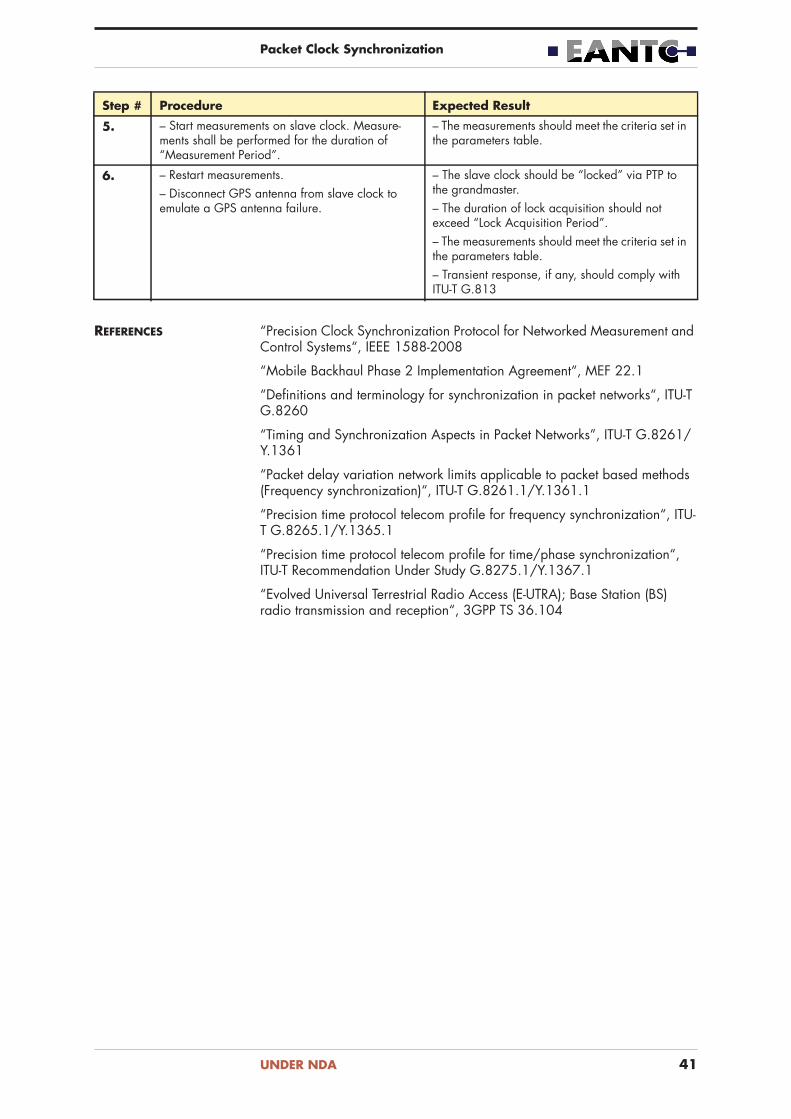
REFERENCES “Precision Clock Synchronization Protocol for Networked Measurement and Control Systems“, IEEE 1588-2008
“Mobile Backhaul Phase 2 Implementation Agreement“, MEF 22.1
“Definitions and terminology for synchronization in packet networks“, ITU-T G.8260
“Timing and Synchronization Aspects in Packet Networks”, ITU-T G.8261/Y.1361
“Packet delay variation network limits applicable to packet based methods (Frequency synchronization)“, ITU-T G.8261.1/Y.1361.1
“Precision time protocol telecom profile for frequency synchronization“, ITU-T G.8265.1/Y.1365.1
“Precision time protocol telecom profile for time/phase synchronization“, ITU-T Recommendation Under Study G.8275.1/Y.1367.1
“Evolved Universal Terrestrial Radio Access (E-UTRA); Base Station (BS) radio transmission and reception“, 3GPP TS 36.104
5. – Start measurements on slave clock. Measure-ments shall be performed for the duration of “Measurement Period”.
– The measurements should meet the criteria set in the parameters table.
6. – Restart measurements.– Disconnect GPS antenna from slave clock to emulate a GPS antenna failure.
– The slave clock should be “locked” via PTP to the grandmaster.– The duration of lock acquisition should not exceed “Lock Acquisition Period”.– The measurements should meet the criteria set in the parameters table.– Transient response, if any, should comply with ITU-T G.813
Step # Procedure Expected Result
UNDER NDA 41

Packet Clock Synchronization
3.2 Phase/Time Hold-Over Performance
PURPOSE Measure the duration a slave clock maintains suitable phase/time accuracy after losing PTP reference source.
DESCRIPTION The goal of this test case is to verify the holdover performance of a PTP (IEEE 1588-2008) slave clock in relation to phase/time stability. We will allow the slave clock to gain a stable lock and emulate a failure in the packet network.
We will measure the synchronization quality using external phase and frequency analyzers at a sync-out interface of the slave clock. We will calcu-late the MTIE (Maximum Time Interval Error) and time of day deviation and compare the results against the synchronization accuracy requirements as listed in the MEF Mobile Backhaul Implementation Agreement Phase 3 (work in progress). To comply with LTE synchronization requirements between the macro base station and small base station. The slave PTP signal should have frequency deviation of no more then 16 ppb and phase deviation (time of day deviation) within ±1.1 s, allowing the end-application to reach an accuracy of ±1.5μs.
We will measure the time period that the this phase requirement is fulfilled while in hold-over. Measurement duration shall not exceed 6 hours.
TEST SETUP • Configure PTP between the slave and grandmaster clocks on a PTP EVC• Slave clock internal oscillator type shall be Quartz-only (XO, OCXO,
TCXO). Rubidium or cesium slave clocks will not be tested due to measurement duration consideration.
• Impairment tool shall be connected between grandmaster and slave clock.
• This test may be performed with SyncE frequency reference as a physical layer backup to PTP.
FIGURE 16. Phase/Time Hold-Over Performance Test Setup
Ethernet link
Data EVC
EVC PTPClock link — Freq.
1PPS link
PSN
SynchronousTraffic Generator/Monitor
Frequency/Phase
Clock link — ToD
Analyzer
Node
ReferenceClock
GrandmasterClock
12:50:00
Impairment Tool
SlaveClock
PARAMETERS DUTs participating in the current test must support the same settings of the IEEE 1588-2008 protocol parameters. The parameter settings profiles are provided by the configuration guide. The table below describes the possible values for the profiles.
UNDER NDA 42

Packet Clock Synchronization
TABLE 23. Parameters – Phase/Time Hold-Over Performance
Parameter Possible Values
PTP Parameters
Transport mode Unicast / Multicast
Encapsulation Ethernet / IPv4 / IPv6
Clock mode Two-way
Delay measurement mechanism End-to-end
Master clock type 1-step / 2-step
Transparent clock type 1-step / 2-step (constrained by master clock type)
Slave clock type 1-step / 2-step (constrained by master clock type)
Delay_Request/Delay_Response Yes
Pdelay_Request/Pdelay_Response No
Sync/Delay_Request/Delay_Response messages rate
64 pps
Announce message rate 0.5 pps (1 message every 2 seconds)
Unicast Request Mechanism (clause 16.1 of IEEE1588-2008)
No / Yes
PTP domain ID 0, 4 – 127
C-VLAN ID 2 – 1000
General parameters
Slave’s clock output interface type (phase measurement)
1PPS
Slave’s clock output interface type (frequency measurement)
E1 / 2048kHz / 10MHz / SyncE
Synchronous Ethernet Optional
IPv4 network/subnet mask (if used) 10.x.y.<HostID>/24
IPv6 address/subnet mask (if used) c10c:x:y::<HostID>/64
Impairment Profile Drop all PTP packets
Lock Acquisition Period 30 minutes (from free-running state)
Measurement Period Up to 6 hours.Shall be stopped after deviation is larger than ±1.1μs (corresponding to ITU-T G.8271 accuracy level 4 in the end application).
Measurement Criteria – The measured MTIE on the slave clock should meet the requirements set by ITU-T G.823 SEC mask.– The time of day deviation should at minimum remain within ±1.1μs, to comply with G.8271 accuracy level 4 (±1.5 s) in the end application.– Transient response shall comply with ITU-T G.8262 EEC Option 1.
UNDER NDA 43

Packet Clock Synchronization
PROCEDURE & EXPECTED RESULTS
TABLE 24. Procedure & Expected Results – Phase/Time Hold-Over Performance
Step # Procedure Expected Result
1. – Ping grandmaster from slave clock. – Ping to grandmaster should be successful.
2. – Force slave clock to free running mode. If not possible, physically reset the slave clock.
– The slave clock should be “free-running” (or is restarted).
3. – Re-enable PTP on slave clock (or wait for slave clock to finish initializing).
– The slave clock should be “locked” via PTP to the grandmaster.– The duration of lock acquisition should not exceed “Lock Acquisition Period”.
4. – Start measurements on slave clock. Measure-ments shall be performed for the duration of “Measurement Period”.
– The measurements should meet the criteria set in the parameters table.
5. – Restart measurements.– Start impairment to drop all PTP packets in both directions between grandmaster and slave clocks.
– The slave clock should be in “hold over” mode.
6. – Continue measurements while the accuracy level complies with ITU-T G.8271 QL4 (±1.5μs) for a maximum of 6 hours.
– The measurements should meet the criteria set in the parameters table.– Transient response, if any, should comply with ITU-T G.813
REFERENCES “Precision Clock Synchronization Protocol for Networked Measurement and Control Systems“, IEEE 1588-2008
“Mobile Backhaul Phase 2 Implementation Agreement“, MEF 22.1
“Definitions and terminology for synchronization in packet networks“, ITU-T G.8260
“Timing and Synchronization Aspects in Packet Networks”, ITU-T G.8261/Y.1361
“Packet delay variation network limits applicable to packet based methods (Frequency synchronization)“, ITU-T G.8261.1/Y.1361.1
“Precision time protocol telecom profile for frequency synchronization“, ITU-T G.8265.1/Y.1365.1
“Precision time protocol telecom profile for time/phase synchronization“, ITU-T Recommendation Under Study G.8275.1/Y.1367.1
“Evolved Universal Terrestrial Radio Access (E-UTRA); Base Station (BS) radio transmission and reception“, 3GPP TS 36.104
UNDER NDA 44

Packet Clock Synchronization
3.3 Precision Time Protocol: Master Clock Scal-ability
PURPOSE Measure the number of clients supported by a PTP master clock (grand-master or boundary clock) while still maintaining a suitable quality level.
DESCRIPTION The goal of this test case is to verify the scalability of a PTP (IEEE 1588-2008) grandmaster clock when it handles a large amount of emulated clients (not exceeding the vendor specifications). We will allow an addi-tional non-emulated slave clock to gain a stable lock and verify that the accuracy fulfills the requirements. Following that, we will start the emulated clients and verify that the accuracy level does not degrade and exceed the boundaries set by the requirements.
We will measure the synchronization quality using external phase and frequency analyzers at a sync-out interface of the slave clock. We will calcu-late the MTIE (Maximum Time Interval Error) and time of day deviation and compare the results against the synchronization accuracy requirements as listed in the MEF Mobile Backhaul Implementation Agreement Phase 3 (work in progress). To comply with LTE synchronization requirements between the macro base station and small base station. The slave PTP signal should have frequency deviation of no more then 16 ppb and phase deviation (time of day deviation) within ±1.1 s, allowing the end-application to reach an accuracy of ±1.5μs.
TEST SETUP • PTP master clock may be a grandmaster clock (test setup 1) or a boundary (test setup 2).
• Emulate a large amount of clients according to the vendor specification to communicate with the PTP master clock. The number of emulated clients shall not exceed <number of supported clients> - 1.
• Configure PTP between the non-emulated slave clock and the master clock.
• Before starting the emulated client, measure the performance at the slave clock output.
TEST SETUP 1 • Configure PTP between the slave clocks and the master clock.
FIGURE 17. Precision Time Protocol: Master Clock Scalability Test Setup 1
Ethernet link
Data EVC
EVC PTPClock link — Freq.
1PPS link
PSN
SynchronousTraffic Generator/Monitor
Frequency/Phase
Clock link — ToD
Analyzer
Node
ReferenceClockImpairment Tool
SlaveClock
Emulated SlaveClocks
GrandmasterClock
12:50:00
UNDER NDA 45

Packet Clock Synchronization
TEST SETUP 2 • Configure PTP domain A between the grandmaster and boundary clocks.• Configure PTP domain B between the boundary and slave clocks.• For each PTP domain, configure VLAN IDs and IP addresses on top of the
VLAN IDs for the PTP transport services. The VLAN ID represents an EVC, that can be mapped by the transport network to a layer 2 transport service. A single multipoint-to-multipoint or multiple point-to-point EVCs may be configured.
• The PTP profile in domain A and the PTP profile in domain B may differ.
FIGURE 18. Precision Time Protocol: Master Clock Scalability Test Setup 2
PTP Domain BEthernet link
Data EVC
EVC PTPClock link — Freq.
1PPS link
PSN
SynchronousTraffic Generator/Monitor
Frequency/Phase
Clock link — ToD
Analyzer
Node
ReferenceClockImpairment Tool
SlaveClock
Emulated SlaveClocks
GrandmasterClock
12:50:00
BoundaryClock
PTP Domain A
PARAMETERS DUTs participating in the current test must support the same settings of the IEEE 1588-2008 protocol parameters. The parameter settings profiles are provided by the configuration guide. The table below describes the possible values for the profiles.
TABLE 25. Parameters – Precision Time Protocol: Master Clock Scalability
Parameter Possible Values
PTP Parameters
Transport mode Unicast / Multicast
Encapsulation Ethernet / IPv4 / IPv6
Clock mode Two-way
Delay measurement mechanism End-to-end
Master clock type 1-step / 2-step
Transparent clock type 1-step / 2-step (constrained by master clock type)
Slave clock type 1-step / 2-step (constrained by master clock type)
Delay_Request/Delay_Response Yes
Pdelay_Request/Pdelay_Response No
Sync/Delay_Request/Delay_Response messages rate
64 pps
Announce message rate 0.5 pps (1 message every 2 seconds)
Unicast Request Mechanism (clause 16.1 of IEEE1588-2008)
No / Yes
PTP domain ID 0, 4 – 127
C-VLAN ID 2 – 1000
UNDER NDA 46

Packet Clock Synchronization
PROCEDURE & EXPECTED RESULTS
TABLE 26. Procedure & Expected Results – Precision Time Protocol: Master Clock Scalability
General parameters
Slave’s clock output interface type (phase measurement)
1PPS
Slave’s clock output interface type (frequency measurement)
E1 / 2048kHz / 10MHz / SyncE
Synchronous Ethernet Disabled
IPv4 network/subnet mask (if used) 10.x.y.<HostID>/24
IPv6 address/subnet mask (if used) c10c:x:y::<HostID>/64
Impairment Profile Based on G.8261 test case 12 network model 2.
Lock Acquisition Period 30 minutes (from free-running state)
Measurement Period 15 minutes (following lock acquisition)
Measurement Criteria – The measured MTIE on the slave clock should meet the requirements set by ITU-T G.823 SEC mask.– The time of day deviation should at minimum remain within ±1.1μs, to comply with G.8271 accuracy level 4 (±1.5 s) in the end application.
Number of emulated PTP clients One less than the vendor specifications (Shall be documented).
Parameter Possible Values
Step # Procedure Expected Result
1. – Test setup 1: Ping grandmaster from slave clock.– Test setup 2: Ping grandmaster and slave clocks from boundary clock.
– Ping should be successful.
2. – Force slave clock to free running mode. If not possible, physically reset the slave clock.
– The slave clock should be “free-running” (or is restarted).– Grandmaster and boundary clock (if used) should be locked and traceable to the reference source.
3. – Re-enable PTP on slave clock (or wait for slave clock to finish initializing).
– The slave clock should be “locked” via PTP to the grandmaster.– The duration of lock acquisition should not exceed “Lock Acquisition Period”.
4. – Start measurements on slave clock. Measure-ments shall be performed for the duration of “Measurement Period”.
– The measurements should meet the criteria set in the parameters table.
UNDER NDA 47

Packet Clock Synchronization
REFERENCES “Precision Clock Synchronization Protocol for Networked Measurement and Control Systems“, IEEE 1588-2008
“Definitions and terminology for synchronization in packet networks“, ITU-T G.8260
“Timing and Synchronization Aspects in Packet Networks”, ITU-T G.8261/Y.1361
“Time and phase synchronization aspects of packet networks“, ITU-T G.8271/Y.1366
“Precision time protocol telecom profile for time/phase synchronization“, ITU-T Recommendation Under Study G.8275.1/Y.1367.1
“Evolved Universal Terrestrial Radio Access (E-UTRA); Base Station (BS) radio transmission and reception“, 3GPP TS 36.104
Vendor specifications for the devices
5. – Restart measurements.– Enable emulated PTP clients.
– Grandmaster should show that the amount of clients served equals device specification.– Slave clock is not expected to change state and remain in “locked” mode.– No transient behavior is expected to be observed in the measurements.
6. – Continue measurements until the measurement duration has expired.
– The measurements should meet the criteria set in the parameters table.
Step # Procedure Expected Result
UNDER NDA 48

Packet Clock Synchronization
3.4 Precision Time Protocol: Boundary Clock Noise Generation (Time/Phase)
PURPOSE Measure the noise generation of a PTPv2 telecom boundary clock (T-BC) in locked mode with respect to time of day/phase accuracy.
DESCRIPTION The goal of this test case is to measure the phase budget consumed by a PTP (IEEE 1588-2008) boundary clock.
We will measure the synchronization quality using external phase and frequency analyzers at a sync-out interface of the slave clock. We will calcu-late the MTIE (Maximum Time Interval Error) and time of day deviation and compare the results against the synchronization accuracy requirements as listed in the MEF Mobile Backhaul Implementation Agreement Phase 3 (work in progress). To comply with LTE synchronization requirements between the macro base station and small base station. The slave PTP signal should have frequency deviation of no more then 16 ppb and phase deviation (time of day deviation) within ±1.1 s, allowing the end-application to reach an accuracy of ±1.5μs.
As expected to be specified in the upcoming ITU-T G.8273.2 (T-BC; Telecom Boundary Clock) specification, the maximum constant time error allowed for a boundary clock shall not exceed 50 ns.
Since the current version of the ITU-T G.8273.2 specification focuses on the case of physical layer frequency support, Synchronous Ethernet (SyncE) is mandatory for this test case.
To accommodate the high accuracy measurements required in this test case, all cable lengths must be properly accounted for. This applies to measure-ment links, reference links and Ethernet links.
TEST SETUP • Configure PTP domain A between the grandmaster and boundary clocks.• Configure PTP domain B between the boundary and slave clocks.• For each PTP domain, configure VLAN IDs and IP addresses on top of the
VLAN IDs for the PTP transport services. The VLAN ID represents an EVC, that can be mapped by the transport network to a layer 2 transport service. A single multipoint-to-multipoint or multiple point-to-point EVCs may be configured.
• The PTP profile in domain A and the PTP profile in domain B may differ.• Slave clock may be emulated in this test case, in which case, no
measurements will be taken from the slave clock (marked as optional in the following test setup figure).
• All measurements should be performed using one analyzer with inte-grated PTP and physical layer (phase and frequency) measurement func-tions in the same clock domain to mitigate possible inaccuracies.
• Measurements may be performed in two forms: either using an analyzer with integrated GM functions (test setup 1) or by measuring the ingress of the BC (test setup 2).
TEST SETUP 1 • Analyzer shall be configured as a grandmaster. This applies only to analyzer with integrated PTP and physical layer measurements in the same clock domain.
• Attach analyzer on the egress of the BC to monitor absolute time error (TE) on PTP traffic originating from the BC.
UNDER NDA 49

Packet Clock Synchronization
FIGURE 19. Precision Time Protocol: Boundary Clock Noise Generation (Time/Phase) Test Setup 1
TP EVC B
PTP EVC AClock link — Freq.
1PPS link PSN
Synchronous
Traffic Monitor
Frequency/Phase
Clock link — ToD
Analyzer NodeSlave Clock
(DUT)
Impairment Tool
ReferenceClock
PTP Domain APTP Domain BOptional
Measurement
Monitor Link
BoundaryClock (DUT)
TEST SETUP 2 • Attach analyzer on the egress of the BC to monitor absolute time error (TE) on PTP traffic originating from the BC.
• Attach analyzer on the ingress of the BC to monitor absolute time error (TE) on PTP traffic originating from the GM.
• The grandmaster participating in this test case must comply with the performance targets of ITU-T G.8272.
FIGURE 20. Precision Time Protocol: Boundary Clock Noise Generation (Time/Phase) Test Setup 2
TP EVC B
PTP EVC AClock link — Freq.
1PPS link PSN
Synchronous
Traffic Monitor
Frequency/Phase
Clock link — ToD
Analyzer NodeGrandmasterClock (DUT)
Slave Clock(DUT)
Impairment Tool
ReferenceClock
BoundaryClock (DUT)
12:50:00
PTP Domain APTP Domain BOptional
Measurement
Monitor Link
PARAMETERS DUTs participating in the current test must support the same settings of the IEEE 1588-2008 protocol parameters. The parameter settings profiles are provided by the configuration guide. The table below describes the possible values for the profiles.
TABLE 27. Parameters – Precision Time Protocol: Boundary Clock Noise Generation (Time/Phase)
Parameter Possible Values
PTP Parameters
Transport mode Unicast / Multicast
Encapsulation Ethernet / IPv4 / IPv6
Clock mode Two-way
Delay measurement mechanism End-to-end
Master clock type 1-step / 2-step
UNDER NDA 50

Packet Clock Synchronization
Transparent clock type 1-step / 2-step (constrained by master clock type)
Slave clock type 1-step / 2-step (constrained by master clock type)
Delay_Request/Delay_Response Yes
Pdelay_Request/Pdelay_Response No
Sync/Delay_Request/Delay_Response messages rate
64 pps
Announce message rate 0.5 pps (1 message every 2 seconds)
Unicast Request Mechanism (clause 16.1 of IEEE1588-2008)
No / Yes
PTP domain ID 0, 4 – 127
C-VLAN ID 2 – 1000
General parameters
Slave’s clock output interface type (phase measurement)
1PPS
Slave’s clock output interface type (frequency measurement)
E1 / 2048kHz / 10MHz / SyncE
Synchronous Ethernet Mandatory
IPv4 network/subnet mask (if used) 10.x.y.<HostID>/24
IPv6 address/subnet mask (if used) c10c:x:y::<HostID>/64
Lock Acquisition Period 30 minutes (from free-running state)
Measurement Period 1000 seconds (following lock acquisi-tion)
General Measurement Criteria – The measured MTIE on the slave clock should meet the requirements set by ITU-T G.823 SEC mask.– The time of day deviation should at minimum remain within ±1.1μs, to comply with G.8271 accuracy level 4 (±1.5 s) in the end application.
T-BC Maximum Constant Time Error 50 ns (T-BC Constant TE Class A)
T-BC MTIE Requirement (Dynamic Error)
40 ns
Parameter Possible Values
UNDER NDA 51

Packet Clock Synchronization
PROCEDURE & EXPECTED RESULTS
TABLE 28. Procedure & Expected Results – Precision Time Protocol: Boundary Clock Noise Generation (Time/Phase)
Step # Procedure Expected Result
1. – Ping grandmaster from boundary clock.– Ping slave clock from boundary clock.Note: This step does not apply for Ethernet Multi-cast encapsulation.
– Ping to grandmaster should be successful.– Ping to slave should be successful.
2. – Force slave clock to free running mode. If not possible, physically reset the slave clock. If slave clock is emulated, stopping the emulation is suffi-cient.– Force boundary clock to free running mode. If not possible, physically reset the slave clock.
– The slave clock should be “free-running” (or is restarted).– The boundary clock should be “free-running” (or is restarted).
3. – Re-enable PTP on slave clock (or wait for slave clock to finish initializing).– Re-enable PTP on boundary clock (or wait for slave clock to finish initializing).
– The slave clock should be “locked” via PTP to the grandmaster.– The duration of lock acquisition should not exceed “Lock Acquisition Period”.
4. – Start measurements on boundary clock. Measurements shall be performed for the duration of “Measurement Period”.– Compare 1PPS output to the PTP Time Error (TE) data.– Optional: Start measurements on slave clock. Measurements shall be performed for the duration of “Measurement Period”.
– The measurements on the boundary clock should meet the criteria set in the parameters “T-BC Maximum Constant Time Error” and “T-BC MTIE Requirement (Dynamic Error)”.– If test setup 2 is used (non-integrated GM), the ingress time error should be accounted for.– 1PPS output should correspond to the TE. A constant offset between the measurements is accepted, but must be documented.– Frequency and phase measurement on boundary clock should meet the criteria set in the parameter “General Measurement Criteria”.
REFERENCES “Timing Characteristics of Telecom Boundary Clocks“, ITU-T Recommenda-tion Under Study G.8273.2
“Timing characteristics of primary reference time clocks“, ITU-T Recommen-dation G.8272
“Precision Clock Synchronization Protocol for Networked Measurement and Control Systems“, IEEE 1588-2008
“Definitions and terminology for synchronization in packet networks“, ITU-T G.8260
“Timing and Synchronization Aspects in Packet Networks”, ITU-T G.8261/Y.1361
“Time and phase synchronization aspects of packet networks“, ITU-T G.8271/Y.1366
“Precision time protocol telecom profile for time/phase synchronization“, ITU-T Recommendation Under Study G.8275.1/Y.1367.1
“Evolved Universal Terrestrial Radio Access (E-UTRA); Base Station (BS) radio transmission and reception“, 3GPP TS 36.104
UNDER NDA 52
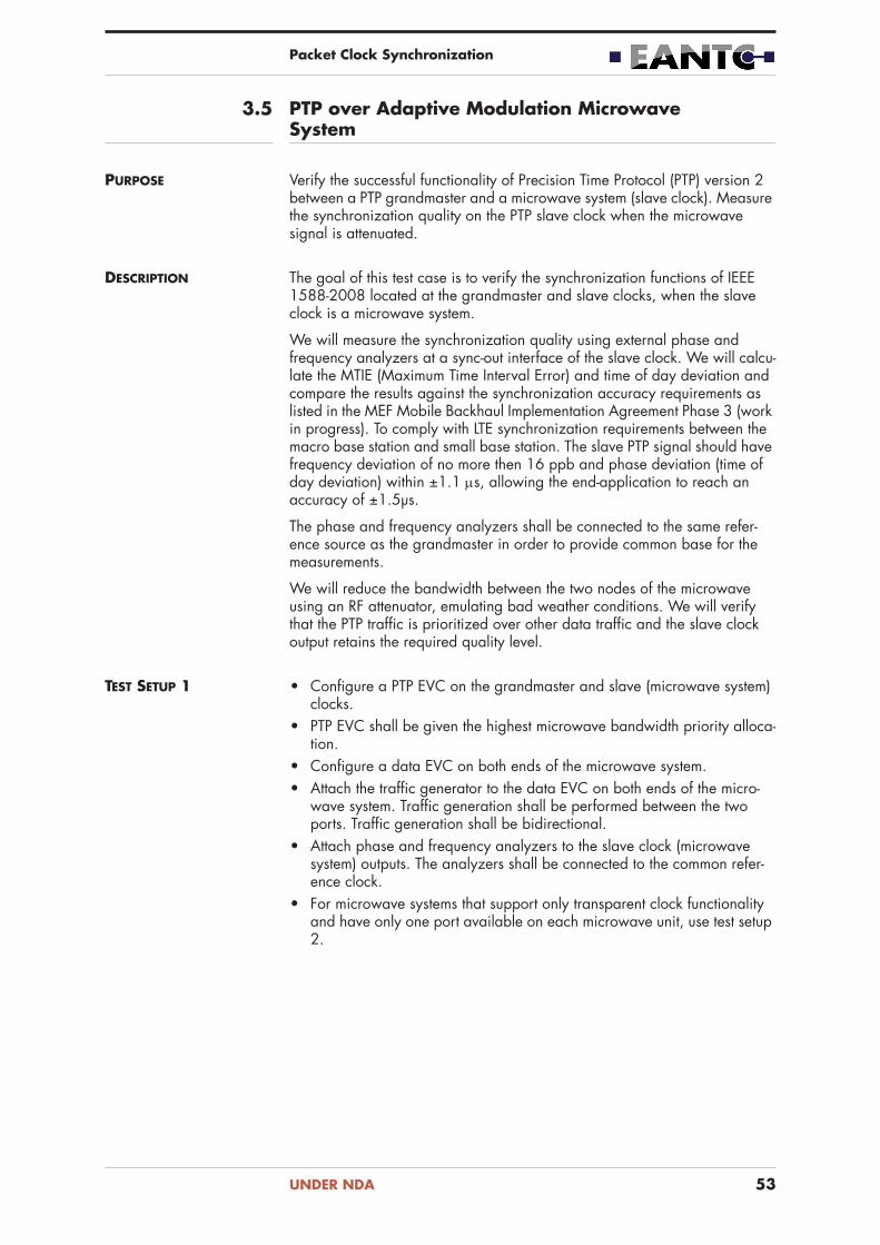
Packet Clock Synchronization
3.5 PTP over Adaptive Modulation Microwave System
PURPOSE Verify the successful functionality of Precision Time Protocol (PTP) version 2 between a PTP grandmaster and a microwave system (slave clock). Measure the synchronization quality on the PTP slave clock when the microwave signal is attenuated.
DESCRIPTION The goal of this test case is to verify the synchronization functions of IEEE 1588-2008 located at the grandmaster and slave clocks, when the slave clock is a microwave system.
We will measure the synchronization quality using external phase and frequency analyzers at a sync-out interface of the slave clock. We will calcu-late the MTIE (Maximum Time Interval Error) and time of day deviation and compare the results against the synchronization accuracy requirements as listed in the MEF Mobile Backhaul Implementation Agreement Phase 3 (work in progress). To comply with LTE synchronization requirements between the macro base station and small base station. The slave PTP signal should have frequency deviation of no more then 16 ppb and phase deviation (time of day deviation) within ±1.1 s, allowing the end-application to reach an accuracy of ±1.5μs.
The phase and frequency analyzers shall be connected to the same refer-ence source as the grandmaster in order to provide common base for the measurements.
We will reduce the bandwidth between the two nodes of the microwave using an RF attenuator, emulating bad weather conditions. We will verify that the PTP traffic is prioritized over other data traffic and the slave clock output retains the required quality level.
TEST SETUP 1 • Configure a PTP EVC on the grandmaster and slave (microwave system) clocks.
• PTP EVC shall be given the highest microwave bandwidth priority alloca-tion.
• Configure a data EVC on both ends of the microwave system.• Attach the traffic generator to the data EVC on both ends of the micro-
wave system. Traffic generation shall be performed between the two ports. Traffic generation shall be bidirectional.
• Attach phase and frequency analyzers to the slave clock (microwave system) outputs. The analyzers shall be connected to the common refer-ence clock.
• For microwave systems that support only transparent clock functionality and have only one port available on each microwave unit, use test setup 2.
UNDER NDA 53

Packet Clock Synchronization
FIGURE 21. PTP over Adaptive Modulation Microwave System Test Setup 1
Microwave link
Data EVC
EVC PTPClock link — Freq.
1PPS link
PSN
Traffic Generator/Monitor(Microwave System)
Frequency/Phase
Clock link — ToD
Analyzer ReferenceClockGrandmaster
Clock
12:50:00
Traffic Generator
RF Attenuator
Slave Clock
TEST SETUP 2 • Configure a PTP EVC on the grandmaster, boundary, transparent and slave (microwave system) clocks.
• PTP EVC shall be given the highest microwave bandwidth priority alloca-tion.
• Configure a data EVC on slave and boundary clock through the trans-parent clock.
• Attach the traffic generator to the data EVC on slave and boundary clocks. Traffic generation shall be performed between the two ports. Traffic generation shall be bidirectional.
• Attach phase and frequency analyzers to the slave clock outputs. The analyzers shall be connected to the common reference clock.
FIGURE 22. PTP over Adaptive Modulation Microwave System Test Setup 2
Microwave link
Data EVC
EVC PTPClock link — Freq.
1PPS link
PSN
Traffic Generator/Monitor
Frequency/Phase
Clock link — ToDAnalyzer ReferenceClock
GrandmasterClock
12:50:00
Traffic Generator
RF Attenuator
Slave Clock BoundaryClock(Microwave System)
Transparent Clock
PARAMETERS DUTs participating in the current test must support the same settings of the IEEE 1588-2008 protocol parameters. The parameter settings profiles are provided by the configuration guide. The table below describes the possible values for the profiles.
UNDER NDA 54

Packet Clock Synchronization
TABLE 29. Parameters – PTP over Adaptive Modulation Microwave System
Parameter Possible Values
PTP Parameters
Transport mode Unicast / Multicast
Encapsulation Ethernet / IPv4 / IPv6
Clock mode Two-way
Delay measurement mechanism End-to-end
Master clock type 1-step / 2-step
Transparent clock type 1-step / 2-step (constrained by master clock type)
Slave clock type 1-step / 2-step (constrained by master clock type)
Delay_Request/Delay_Response Yes
Pdelay_Request/Pdelay_Response No
Sync/Delay_Request/Delay_Response messages rate
64 pps
Announce message rate 0.5 pps (1 message every 2 seconds)
Unicast Request Mechanism (clause 16.1 of IEEE1588-2008)
No / Yes
PTP domain ID 0, 4 – 127
C-VLAN ID 2 – 1000
General parameters
Slave’s clock output interface type (phase measurement)
1PPS
Slave’s clock output interface type (frequency measurement)
E1 / 2048kHz / 10MHz / SyncE
Synchronous Ethernet Disabled
IPv4 network/subnet mask (if used) 10.x.y.<HostID>/24
IPv6 address/subnet mask (if used) c10c:x:y::<HostID>/64
Traffic flow definition Bidirectional traffic according to the profile defined in G.8261 VI2.2:– Constant bit rate at 10% of the line rate with 576 byte packets.– Constant bit rate at 30% line rate with 64 byte packets.– Traffic bursts at 60% with 1518 byte packets.– Bursts shall last between 100 ms and 3 seconds.– Inter-burst time shall be 16 ms.– Line rate shall equal the maximal bandwidth of the MW node when no attenuation is applied.
Lock Acquisition Period 30 minutes (from free-running state)
UNDER NDA 55

Packet Clock Synchronization
PROCEDURE & EXPECTED RESULTS
TABLE 30. Procedure & Expected Results – PTP over Adaptive Modulation Microwave System
Measurement Period 15 minutes (following lock acquisition)
Measurement Criteria – The measured MTIE on the slave clock should meet the requirements set by ITU-T G.823 SEC mask.– The time of day deviation should at minimum remain within ±1.1μs, to comply with G.8271 accuracy level 4 (±1.5 s) in the end application.
Parameter Possible Values
Step # Procedure Expected Result
Part A: Normal Operating Conditions
1. – Ping grandmaster from slave clock. – Ping to grandmaster should be successful.
2. – Configure a traffic flow according to the “Traffic flow definition” parameter.– After impairment generation started, reset slave clock to free-running state. If required, reset the device to ensure free-running state.– Display the internal clock status on each DUT.
– The slave clock status should be free-running.
3. – Reset traffic statistics on traffic generator and microwave system.– Generate traffic for 30 seconds.
– The test traffic should be forwarded without loss.– The traffic generator statistics should match with the microwave system interface statistics.
4. – Enable PTP on slave clock. – The slave clock should be “locked”.– The duration of lock acquisition should not exceed “Lock Acquisition Period”.
5. – Start measurements on slave clock. Measure-ments shall be performed for the duration of “Measurement Period”.
– The measurements should meet the criteria set in the parameters table.
Part B: Reduced Bandwidth Operating Conditions
6. – Apply attenuation to the microwave system, such that the minimal bandwidth mode is in use. Note the attenuation level applied and the band-width.– Reset slave clock to free-running state. If required, reset the microwave system to ensure free-running state.– Display the internal clock status on the micro-wave system.
– The slave clock status should be free-running.
7. – Reset traffic statistics on traffic generator and microwave system.
– Loss to test traffic is expected according to the bandwidth available at the lowest bandwidth mode.
UNDER NDA 56

Packet Clock Synchronization
REFERENCES “Precision Clock Synchronization Protocol for Networked Measurement and Control Systems“, IEEE 1588-2008
“Mobile Backhaul Phase 3 Implementation Agreement“, MEF 22.2 (work in progress)
“Definitions and terminology for synchronization in packet networks“, ITU-T G.8260
“Timing and Synchronization Aspects in Packet Networks”, ITU-T G.8261/Y.1361
“Packet delay variation network limits applicable to packet based methods (Frequency synchronization)“, ITU-T G.8261.1/Y.1361.1
“Precision time protocol telecom profile for frequency synchronization“, ITU-T G.8265.1/Y.1365.1
“Precision time protocol telecom profile for time/phase synchronization“, ITU-T Recommendation Under Study G.8275.1/Y.1367.1
“Evolved Universal Terrestrial Radio Access (E-UTRA); Base Station (BS) radio transmission and reception“, 3GPP TS 36.104
8. – Enable PTP on slave clock. – The slave clock should be “locked”.– The duration of lock acquisition should not exceed “Lock Acquisition Period”.
9. – Start measurements on slave clock. Measure-ments shall be performed for the duration of “Measurement Period”.
– The measurements should meet the criteria set in the parameters table.
Step # Procedure Expected Result
UNDER NDA 57

Packet Clock Synchronization
3.6 Precision Time Protocol: Transparent Clock Scalability
PURPOSE Measure the correction field accuracy of a PTP transparent clock when serving one PTP client compare to serving a large number of clients.
DESCRIPTION The goal of this test case is to verify the scalability of a PTP (IEEE 1588-2008) transparent clock when it handles a large amount of emulated clients (not exceeding the vendor specifications). We will allow an additional non-emulated slave clock to gain a stable lock and verify that the accuracy fulfills the requirements. Following that, we will start the emulated clients and verify that the accuracy level does not degrade and exceed the boundaries set by the requirements. Accuracy level will be determined by measuring the correction field accuracy in those two scenarios.
We will measure the synchronization quality using external phase and frequency analyzers at a sync-out interface of the slave clock. We will calcu-late the MTIE (Maximum Time Interval Error) and time of day deviation and compare the results against the synchronization accuracy requirements as listed in the MEF Mobile Backhaul Implementation Agreement Phase 3 (work in progress). To comply with LTE synchronization requirements between the macro base station and small base station. The slave PTP signal should have frequency deviation of no more then 16 ppb and phase deviation (time of day deviation) within ±1.1 s, allowing the end-application to reach an accuracy of ±1.5μs.
TEST SETUP • Configure PTP between the slave clocks and the master clock.• Emulate a large amount of clients according to the vendor specification
to communicate with the PTP master clock. The number of emulated clients shall not exceed <number of supported clients> - 1.
• Configure PTP between the non-emulated slave clock and the master clock.
• Before starting the emulated client, measure the performance at the slave clock output.
• Connect two links from the analyzer on the ingress from the grandmaster and egress towards the non-emulated slave clock. Filter PTP message to match only the non-emulated slave clock IP address / MAC address.
FIGURE 23. Precision Time Protocol: Transparent Clock Scalability Test Setup
Ethernet link
Data EVC
EVC PTPClock link — Freq.
1PPS link
PSN
SynchronousTraffic Generator/Monitor
Frequency/Phase
Clock link — ToD
Analyzer
Node
ReferenceClockImpairment Tool
SlaveClock
Emulated SlaveClocks
GrandmasterClock
12:50:00
TransparentClock
UNDER NDA 58

Packet Clock Synchronization
PARAMETERS DUTs participating in the current test must support the same settings of the IEEE 1588-2008 protocol parameters. The parameter settings profiles are provided by the configuration guide. The table below describes the possible values for the profiles.
TABLE 31. Parameters – Precision Time Protocol: Transparent Clock Scalability
Parameter Possible Values
PTP Parameters
Transport mode Unicast / Multicast
Encapsulation Ethernet / IPv4 / IPv6
Clock mode Two-way
Delay measurement mechanism End-to-end
Master clock type 1-step / 2-step
Transparent clock type 1-step / 2-step (constrained by master clock type)
Slave clock type 1-step / 2-step (constrained by master clock type)
Delay_Request/Delay_Response Yes
Pdelay_Request/Pdelay_Response No
Sync/Delay_Request/Delay_Response messages rate
64 pps
Announce message rate 0.5 pps (1 message every 2 seconds)
Unicast Request Mechanism (clause 16.1 of IEEE1588-2008)
No / Yes
PTP domain ID 0, 4 – 127
C-VLAN ID 2 – 1000
General parameters
Slave’s clock output interface type (phase measurement)
1PPS
Slave’s clock output interface type (frequency measurement)
E1 / 2048kHz / 10MHz / SyncE
Synchronous Ethernet Optional
IPv4 network/subnet mask (if used) 10.x.y.<HostID>/24
IPv6 address/subnet mask (if used) c10c:x:y::<HostID>/64
Lock Acquisition Period 15 minutes (from free-running state)
Measurement Period 15 minutes (following lock acquisition)
Measurement Criteria – The measured MTIE on the slave clock should meet the requirements set by ITU-T G.823 SEC mask.– The time of day deviation should at minimum remain within ±1.1μs, to comply with G.8271 accuracy level 4 (±1.5 s) in the end application.
Number of emulated PTP clients One less than the vendor specifications (Shall be documented), bounded by the number of clients supported by the grandmaster clock.
Transparent Clock Correction Field Accuracy
50 ns
UNDER NDA 59
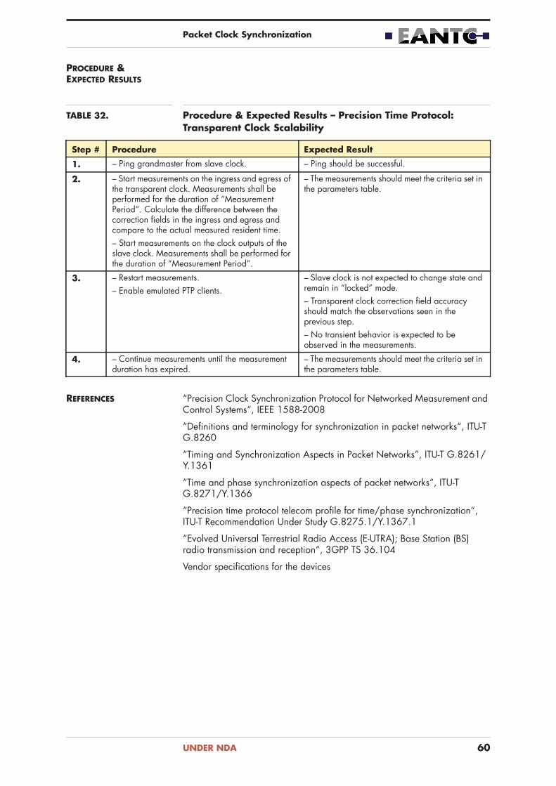
Packet Clock Synchronization
PROCEDURE & EXPECTED RESULTS
TABLE 32. Procedure & Expected Results – Precision Time Protocol: Transparent Clock Scalability
Step # Procedure Expected Result
1. – Ping grandmaster from slave clock. – Ping should be successful.
2. – Start measurements on the ingress and egress of the transparent clock. Measurements shall be performed for the duration of “Measurement Period”. Calculate the difference between the correction fields in the ingress and egress and compare to the actual measured resident time.– Start measurements on the clock outputs of the slave clock. Measurements shall be performed for the duration of “Measurement Period”.
– The measurements should meet the criteria set in the parameters table.
3. – Restart measurements.– Enable emulated PTP clients.
– Slave clock is not expected to change state and remain in “locked” mode.– Transparent clock correction field accuracy should match the observations seen in the previous step.– No transient behavior is expected to be observed in the measurements.
4. – Continue measurements until the measurement duration has expired.
– The measurements should meet the criteria set in the parameters table.
REFERENCES “Precision Clock Synchronization Protocol for Networked Measurement and Control Systems“, IEEE 1588-2008
“Definitions and terminology for synchronization in packet networks“, ITU-T G.8260
“Timing and Synchronization Aspects in Packet Networks”, ITU-T G.8261/Y.1361
“Time and phase synchronization aspects of packet networks“, ITU-T G.8271/Y.1366
“Precision time protocol telecom profile for time/phase synchronization“, ITU-T Recommendation Under Study G.8275.1/Y.1367.1
“Evolved Universal Terrestrial Radio Access (E-UTRA); Base Station (BS) radio transmission and reception“, 3GPP TS 36.104
Vendor specifications for the devices
UNDER NDA 60